WO2020161816A1 - 複合現実表示装置および複合現実表示方法 - Google Patents
複合現実表示装置および複合現実表示方法 Download PDFInfo
- Publication number
- WO2020161816A1 WO2020161816A1 PCT/JP2019/004191 JP2019004191W WO2020161816A1 WO 2020161816 A1 WO2020161816 A1 WO 2020161816A1 JP 2019004191 W JP2019004191 W JP 2019004191W WO 2020161816 A1 WO2020161816 A1 WO 2020161816A1
- Authority
- WO
- WIPO (PCT)
- Prior art keywords
- mixed reality
- reality display
- image
- virtual object
- real
- Prior art date
- Legal status (The legal status is an assumption and is not a legal conclusion. Google has not performed a legal analysis and makes no representation as to the accuracy of the status listed.)
- Ceased
Links
Images












Classifications
-
- G—PHYSICS
- G06—COMPUTING OR CALCULATING; COUNTING
- G06F—ELECTRIC DIGITAL DATA PROCESSING
- G06F3/00—Input arrangements for transferring data to be processed into a form capable of being handled by the computer; Output arrangements for transferring data from processing unit to output unit, e.g. interface arrangements
- G06F3/01—Input arrangements or combined input and output arrangements for interaction between user and computer
- G06F3/011—Arrangements for interaction with the human body, e.g. for user immersion in virtual reality
- G06F3/012—Head tracking input arrangements
-
- G—PHYSICS
- G06—COMPUTING OR CALCULATING; COUNTING
- G06F—ELECTRIC DIGITAL DATA PROCESSING
- G06F13/00—Interconnection of, or transfer of information or other signals between, memories, input/output devices or central processing units
-
- G—PHYSICS
- G06—COMPUTING OR CALCULATING; COUNTING
- G06F—ELECTRIC DIGITAL DATA PROCESSING
- G06F3/00—Input arrangements for transferring data to be processed into a form capable of being handled by the computer; Output arrangements for transferring data from processing unit to output unit, e.g. interface arrangements
- G06F3/01—Input arrangements or combined input and output arrangements for interaction between user and computer
- G06F3/011—Arrangements for interaction with the human body, e.g. for user immersion in virtual reality
-
- G—PHYSICS
- G06—COMPUTING OR CALCULATING; COUNTING
- G06F—ELECTRIC DIGITAL DATA PROCESSING
- G06F3/00—Input arrangements for transferring data to be processed into a form capable of being handled by the computer; Output arrangements for transferring data from processing unit to output unit, e.g. interface arrangements
- G06F3/14—Digital output to display device ; Cooperation and interconnection of the display device with other functional units
- G06F3/1423—Digital output to display device ; Cooperation and interconnection of the display device with other functional units controlling a plurality of local displays, e.g. CRT and flat panel display
-
- G—PHYSICS
- G06—COMPUTING OR CALCULATING; COUNTING
- G06F—ELECTRIC DIGITAL DATA PROCESSING
- G06F3/00—Input arrangements for transferring data to be processed into a form capable of being handled by the computer; Output arrangements for transferring data from processing unit to output unit, e.g. interface arrangements
- G06F3/14—Digital output to display device ; Cooperation and interconnection of the display device with other functional units
- G06F3/1454—Digital output to display device ; Cooperation and interconnection of the display device with other functional units involving copying of the display data of a local workstation or window to a remote workstation or window so that an actual copy of the data is displayed simultaneously on two or more displays, e.g. teledisplay
-
- G—PHYSICS
- G06—COMPUTING OR CALCULATING; COUNTING
- G06T—IMAGE DATA PROCESSING OR GENERATION, IN GENERAL
- G06T15/00—Three-dimensional [3D] image rendering
- G06T15/10—Geometric effects
- G06T15/40—Hidden part removal
-
- G—PHYSICS
- G06—COMPUTING OR CALCULATING; COUNTING
- G06T—IMAGE DATA PROCESSING OR GENERATION, IN GENERAL
- G06T19/00—Manipulating three-dimensional [3D] models or images for computer graphics
- G06T19/006—Mixed reality
-
- G—PHYSICS
- G06—COMPUTING OR CALCULATING; COUNTING
- G06T—IMAGE DATA PROCESSING OR GENERATION, IN GENERAL
- G06T19/00—Manipulating three-dimensional [3D] models or images for computer graphics
- G06T19/20—Editing of three-dimensional [3D] images, e.g. changing shapes or colours, aligning objects or positioning parts
-
- G—PHYSICS
- G06—COMPUTING OR CALCULATING; COUNTING
- G06T—IMAGE DATA PROCESSING OR GENERATION, IN GENERAL
- G06T7/00—Image analysis
- G06T7/10—Segmentation; Edge detection
- G06T7/194—Segmentation; Edge detection involving foreground-background segmentation
-
- G—PHYSICS
- G06—COMPUTING OR CALCULATING; COUNTING
- G06T—IMAGE DATA PROCESSING OR GENERATION, IN GENERAL
- G06T7/00—Image analysis
- G06T7/50—Depth or shape recovery
-
- G—PHYSICS
- G06—COMPUTING OR CALCULATING; COUNTING
- G06V—IMAGE OR VIDEO RECOGNITION OR UNDERSTANDING
- G06V20/00—Scenes; Scene-specific elements
- G06V20/20—Scenes; Scene-specific elements in augmented reality scenes
-
- H—ELECTRICITY
- H04—ELECTRIC COMMUNICATION TECHNIQUE
- H04L—TRANSMISSION OF DIGITAL INFORMATION, e.g. TELEGRAPHIC COMMUNICATION
- H04L67/00—Network arrangements or protocols for supporting network services or applications
- H04L67/01—Protocols
- H04L67/131—Protocols for games, networked simulations or virtual reality
-
- H—ELECTRICITY
- H04—ELECTRIC COMMUNICATION TECHNIQUE
- H04N—PICTORIAL COMMUNICATION, e.g. TELEVISION
- H04N13/00—Stereoscopic video systems; Multi-view video systems; Details thereof
- H04N13/30—Image reproducers
- H04N13/363—Image reproducers using image projection screens
-
- G—PHYSICS
- G02—OPTICS
- G02B—OPTICAL ELEMENTS, SYSTEMS OR APPARATUS
- G02B27/00—Optical systems or apparatus not provided for by any of the groups G02B1/00 - G02B26/00, G02B30/00
- G02B27/01—Head-up displays
- G02B27/017—Head mounted
-
- G—PHYSICS
- G06—COMPUTING OR CALCULATING; COUNTING
- G06T—IMAGE DATA PROCESSING OR GENERATION, IN GENERAL
- G06T2200/00—Indexing scheme for image data processing or generation, in general
- G06T2200/24—Indexing scheme for image data processing or generation, in general involving graphical user interfaces [GUIs]
-
- G—PHYSICS
- G06—COMPUTING OR CALCULATING; COUNTING
- G06T—IMAGE DATA PROCESSING OR GENERATION, IN GENERAL
- G06T2210/00—Indexing scheme for image generation or computer graphics
- G06T2210/04—Architectural design, interior design
-
- G—PHYSICS
- G06—COMPUTING OR CALCULATING; COUNTING
- G06T—IMAGE DATA PROCESSING OR GENERATION, IN GENERAL
- G06T2219/00—Indexing scheme for manipulating 3D models or images for computer graphics
- G06T2219/024—Multi-user, collaborative environment
-
- G—PHYSICS
- G06—COMPUTING OR CALCULATING; COUNTING
- G06T—IMAGE DATA PROCESSING OR GENERATION, IN GENERAL
- G06T2219/00—Indexing scheme for manipulating 3D models or images for computer graphics
- G06T2219/20—Indexing scheme for editing of 3D models
- G06T2219/2016—Rotation, translation, scaling
-
- G—PHYSICS
- G06—COMPUTING OR CALCULATING; COUNTING
- G06T—IMAGE DATA PROCESSING OR GENERATION, IN GENERAL
- G06T2219/00—Indexing scheme for manipulating 3D models or images for computer graphics
- G06T2219/20—Indexing scheme for editing of 3D models
- G06T2219/2021—Shape modification
-
- G—PHYSICS
- G06—COMPUTING OR CALCULATING; COUNTING
- G06T—IMAGE DATA PROCESSING OR GENERATION, IN GENERAL
- G06T2219/00—Indexing scheme for manipulating 3D models or images for computer graphics
- G06T2219/20—Indexing scheme for editing of 3D models
- G06T2219/2024—Style variation
-
- G—PHYSICS
- G09—EDUCATION; CRYPTOGRAPHY; DISPLAY; ADVERTISING; SEALS
- G09G—ARRANGEMENTS OR CIRCUITS FOR CONTROL OF INDICATING DEVICES USING STATIC MEANS TO PRESENT VARIABLE INFORMATION
- G09G2360/00—Aspects of the architecture of display systems
- G09G2360/14—Detecting light within display terminals, e.g. using a single or a plurality of photosensors
- G09G2360/144—Detecting light within display terminals, e.g. using a single or a plurality of photosensors the light being ambient light
-
- G—PHYSICS
- G09—EDUCATION; CRYPTOGRAPHY; DISPLAY; ADVERTISING; SEALS
- G09G—ARRANGEMENTS OR CIRCUITS FOR CONTROL OF INDICATING DEVICES USING STATIC MEANS TO PRESENT VARIABLE INFORMATION
- G09G2370/00—Aspects of data communication
- G09G2370/16—Use of wireless transmission of display information
Definitions
- the present invention relates to a mixed reality display device and a mixed reality display method for experiencing a mixed reality (MR) space in which a real space and a virtual object are combined.
- the present invention relates to a technique suitable for a plurality of MR users to share the MR experience.
- AR augmented reality
- CG Computer Graphics
- Adding an augmented reality (AR) object which is a virtual object created by CG (Computer Graphics)
- an image called an AR trigger or a marker is photographed at the same time as the background by a camera, and the AR object to be linked by the AR trigger is combined with a real image.
- a head-mounted display (HMD) in which a camera and a display are integrated is used to generate an image according to the position and orientation of the HMD based on an image of a real space taken by a camera mounted on the HMD.
- the AR object is superimposed and displayed as a video of the virtual object in the real space.
- Patent Document 1 describes an MR system that combines a mobile information terminal such as a tablet in addition to the HMD so that a plurality of people can share the MR experience.
- the MR image displayed on the HMD is also displayed on the tablet, and the user of the tablet can designate a virtual object in the shared MR image and reflect the designated result on the MR image. It is stated that it is possible.
- the user of the mobile information terminal can only specify the virtual object, and cannot perform the operation of arranging or replacing the virtual object in the real space. Also, the physical space of the HMD can be shared, but the physical space of the user of the mobile information terminal cannot be shared.
- Patent Document 1 when a plurality of people experience the MR space, other experienced people except the HMD wearer cannot perform the operation of arranging or replacing the virtual object in the real space, and still another one. There is a problem that it is not possible to share the physical space of the experienced person.
- the present invention has been made in view of the above points, and an object thereof is, when a plurality of people experience the MR space, a plurality of experienced people arrange or replace virtual objects in the real space at the same time.
- An object of the present invention is to provide a mixed reality display device and a mixed reality display method that can be operated and can share the physical spaces of a plurality of users.
- the mixed reality display device of the present invention is configured to connect to another mixed reality display device worn by another experiencer and share a real image and a virtual object image with each other.
- a camera for capturing a real image a controller for recognizing a real object from the real image captured by the camera, and for tying a predetermined virtual object to the recognized real object based on an operation by a user, and a virtual object for tying And a memory for storing data of a virtual object associated with a physical object, and a communication unit for connecting to another mixed reality display device to transmit and receive data.
- the controller acquires the recognition result of the real object generated by another mixed reality display device and the data of the associated virtual object via the communication unit, and combines the acquired data with the data stored in the memory. Then, the synthesized image is displayed on the display unit, and a virtual object linked to a real object can be edited on the image displayed on the display unit based on an operation by a user.
- the mixed reality display method of the present invention includes the steps of shooting a real image with a plurality of mixed reality display devices, connecting the taken real images to recognize a real object, and selecting based on the operation of each experiencer.
- a plurality of experience persons when a plurality of people experience the MR space, a plurality of experience persons can perform operations such as arranging or replacing virtual objects in the real space, and sharing the real space of the plurality of experience persons. It becomes possible to do.
- FIG. 3 is a diagram showing an external configuration of the MR display device according to the first embodiment.
- FIG. 3 is a block diagram showing a functional configuration of the MR display device 1.
- the flowchart of the whole control process 81. 9 is a flowchart of reference point/movement history processing 82. 9 is a flowchart of synchronization/priority processing 83.
- the flowchart of AR object processing 86 (case 1).
- FIG. 9 is a diagram showing an example of an MR space according to the second embodiment.
- the flowchart of AR object processing 86 (addition).
- a data table of imaged object data A data table of AR object data.
- FIG. 6 is a diagram showing a configuration of an MR network system according to a third embodiment.
- the sequence diagram of MR network system The figure which shows the detail of the sequence of FIG. 18A.
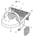
- FIG. 9 is a diagram showing an external configuration of an MR display device 1 ′ according to Example 4.
- the mixed reality display device is also referred to as an MR display device or an HMD.
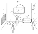
- FIG. 1A is a diagram showing an example of a physical space to which a plurality of MR display devices are applied.
- This system has three MR display devices (HMDs) 1a, 1b, 1c, and a plurality of experienced persons 2a, 2b, 2c in the MR space wear the HMDs 1a, 1b, 1c on their heads.
- HMDs MR display devices
- each HMD has a built-in camera, distance measuring sensor, display, communication unit, position/orientation sensor, shoots the real space with the camera, and the MR image displayed on the display allows the experience person to acquire MR images. To see.
- Reference numerals 3a, 3b, and 3c represent the photographing field angles of the cameras built in the HMDs 1a, 1b, and 1c.
- an access point (AP) 5 such as a wireless LAN is provided for communication among the HMDs 1a, 1b, 1c. Since the position of the experience person (HMD) and the line-of-sight direction are different, the real spaces visually recognized by each are different, but by communicating between the HMDs, a common MR image can be experienced.
- the walls 4a, 4b, 4c and the floor 4d of the room are the background.
- a window 6, a sofa 7, a projector 8 and a projection screen 8a of the projector 8 are placed on it as real objects.
- the MR experienced persons 2a, 2b, 2c have an MR experience in this physical space. Specifically, a scene in which a plurality of workers (MR experienced persons) lay out the interior of the room is assumed as an example.
- the experienced persons 2a, 2b, 2c perform the initial setting (coordinate adjustment) of the line-of-sight direction (camera shooting direction) and the position and height.
- the window 6 is photographed by the camera, the corners 6b and 6c of the window 6 are made symmetrical with respect to the center 6a of the display screen of the HMD, and the photographing direction reference is determined.
- the window 6 is moved to a position at a predetermined distance and set as a reference position.
- the height of the HMD depending on the height of the experience person is registered as a reference point.
- the experience points 2a, 2b, and 2c perform registration of the reference points
- the height difference between the experience persons 2b and 2c may be corrected with reference to the height of the experience person 2.
- the movements of the experienced persons 2a, 2b, 2c after registration of the reference points are detected by the position/direction sensor and recorded as movement history data. Thereby, the position data of each experiencer can be expressed by a common coordinate system.
- the initialization method is not limited to the above method, and may be a method using a GPS sensor or an azimuth center, as long as it is possible to share the reference point among the MR space experienced persons.
- Angles of view 3a, 3b, 3c that can be taken with the HMD camera are only a part of the real space.
- the captured images of the captured view angles 3a, 3b, 3c acquired by the HMDs 1a, 1b, 1c are combined to generate a coupled real space image (background image).
- the position, direction, and height of each HMD at the time of shooting are converted from viewpoints as if they were shot from the reference point and combined.
- the connection of the background images is repeated every time the experienced persons 2a, 2b, 2c move, and the overlapping portions are updated with new background images.
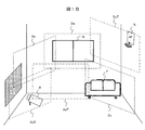
- FIG. 1B is a diagram showing a state in which background images are connected.
- a range 3a for shooting with the HMD 1a (shooting angle of view in FIG. 1A), a range 3b for shooting with the HMD 1b, and a range 3c for shooting with the HMD 1c are background images at different shooting positions.
- the viewpoints of these images are converted into images captured from the reference points, and the images are mapped in the 360-degree space around the reference point to form a connected background image.
- the 360-degree all-round space does not mean that the shooting range 3a, 3b, 3c covers the entire space.
- each HMD 1a, 1b, 1c (each experienced person 2a, 2b, 2c) moves and takes a picture at a new photographing range 3aT, 3bT, 3cT at the next time T.
- the viewpoints of the images in the shooting ranges 3aT, 3bT, and 3cT are converted and added to the connected background image to expand the space of the background image.
- it is especially easy to connect by expanding characteristic points such as wall boundaries, tangents between floors and walls, and window frames.
- the overlapping background image portion is temporally replaced with a new background image portion to update the background image.
- the background object data may be connected after the background object data described below is acquired instead of the HMD captured image. Further, each HMD may acquire the photographed object data and the background object data from the photographed video, share the photographed object data acquired by each HMD, and connect the background object data.
- the sofa 7 cannot be captured with the view angle 3b of the camera of the experience person 2b
- the projector 8 cannot be captured with the view angle 3c of the camera of the experience person 2c. ..
- the presence of the sofa 7 and the projector 8 is recognized, and the recognized information is used as a photographing object to be described later. It can be shared by the experienced persons 2a, 2b, 2c.
- FIG. 2 is a diagram illustrating an external configuration of the MR display device according to the first embodiment.
- the MR display device (HMD) 1 (1a to 1c) includes a camera 10, a distance measuring sensor 11, a position/orientation sensor 12, a 3D projector 13, a transmissive screen 14, glasses with shutters 15, a controller 16, speakers 17a and 17b, Holders 18a and 18b and a microphone 19 are provided.
- the MR experience person 2 mounts the HMD 1 on his/her head with the holders 18a and 18b.
- the camera 10 is attached so as to photograph the front of the head (the direction of the line of sight of the user), and the distance measuring sensor 11 measures the distance to the real object captured by the image captured by the camera 10.
- the position/direction sensor 12 includes a gyro, a position, and a direction sensor, and detects the position and the line-of-sight direction of the experience person.
- the distance-measuring sensor 11 may be one that two-dimensionally irradiates a light beam such as a TOF (Time of Flight) method to measure the distance, or a distance such as a stereo camera to a feature point such as a contour. May be calculated, as long as it is possible to measure the distance between the camera and the physical object in correspondence with the image captured by the camera.
- a light beam such as a TOF (Time of Flight) method to measure the distance
- a distance such as a stereo camera to a feature point such as a contour. May be calculated, as long as it is possible to measure the distance between the camera and the physical object in correspondence with the image captured by the camera.
- the 3D projector 13 projects a 3D virtual object (AR object) on the transmissive screen 14 by alternately projecting an image confirmed by the left eye and an image confirmed by the right eye.
- the shutter-equipped eyeglasses 15 transmit the image alternately to the left and right in synchronization with this.
- the experience person 2 can see the scenery in front and the real object through the transmissive screen 14, and also can visually recognize the 3D virtual object projected by the 3D projector 13 on the transmissive screen 14 in a superposed manner. it can.
- the controller 16 fetches the image captured by the camera 10, the distance data of the distance measuring sensor 11, and the position/direction data of the position/direction sensor 12, and supplies it to the internal memory or CPU. Also, the image projected by the 3D projector 13 and the sound output to the speakers 17a and 17b are created. Further, a drive signal for the glasses with shutters 15 is generated, the transmission of the left and right glasses is switched in synchronization with the image of the AR object projected by the 3D projector 13, and the 3D image is provided to the experience person.
- the controller 16 also includes a user interface with the MR experience person 2.
- the user interface can use a panel having a built-in touch sensor.
- FIG. 3 is a block diagram showing a functional configuration of the MR display device 1.
- the same parts as those in FIG. 2 are designated by the same reference numerals.
- a feature extraction processing unit 61 Inside the controller 16 of the HMD 1 (shown by a broken line), a feature extraction processing unit 61, a distance calculation processing unit 62, a movement detection processing unit 63, a communication unit 64, a CPU 65, a RAM 66, an image RAM 67, a program flash ROM (P-FROM). ) 68, a data flash ROM (D-FROM) 69, and a user operation input unit 60.
- P-FROM program flash ROM
- D-FROM data flash ROM
- the feature extraction processing unit 61 extracts the contour (edge) of the physical object from the video image captured by the camera 10 and performs the processing using the inflection point or the vertex of the contour as the feature point.
- the distance calculation processing unit 62 calculates the distance to the feature point based on the measurement data from the distance measuring sensor 11.
- the movement detection processing unit 63 obtains the position and movement amount of the HMD 1 and the shooting direction of the camera 10 based on the measurement data from the position/orientation sensor 12, that is, this is the position and movement amount of the experience person 2, and the line of sight. Direction.
- the communication unit 64 connects the HMD 1 to the access point 5 and exchanges data with another HMD 1.
- a part of the processing of the HMD 1 can be performed by a server or the like connected to the external network and connected to the external network.
- the program flash ROM 68 stores various processing programs. This includes overall control processing 81, reference point/movement history processing 82, synchronization/priority processing 83, shooting object processing 84, background object processing 85, AR object processing 86, and display video generation processing 87. These processing programs are expanded in the RAM 66 and executed by the CPU 65.
- the data flash ROM 69 stores data generated in the process of executing these processing programs and as a result. This includes reference point/movement history data 91, imaged object data 92, background object data 93, and AR object data 94. From this, when the experience person wants to reproduce and experience the MR space, it can be realized by reading out the data stored therein.
- program flash ROM 68 and the data flash ROM 69 may be configured by separate memory media as illustrated, or may be configured by one memory medium. Further, it may be two or more memory media, and may be a non-volatile memory medium other than the flash ROM.
- the data flash ROM 69 may be placed in a data server on the network.
- the video data generated by the display video generation processing 87 is stored in the image RAM 67, read from the image RAM 67, and projected by the 3D projector 13.
- the user operation input unit 60 receives a user input by the touch sensor, and the 3D projector 13 projects a control menu image on the transmissive screen 14 to control the HMD 1.
- a physical object is recognized and registered as a shooting object or a background object.
- the room as a real space is surrounded by a front wall 4a, a left side wall 4b, a right side wall 4c, and a floor 4d, and has a window 6, a sofa 7, and a projector 8.
- the cameras 10 of the plurality of HMDs 1 photograph these physical objects, and the feature extraction processing unit 61 extracts the contours (edges) of the physical objects and performs processing using inflection points or vertices of the contours as feature points.
- the set of feature points forming the contour is sent to the CPU 65 to identify what the object is. At that time, the object may be identified by collating with the video database of an external server via the communication unit 64.
- the distance measuring sensor 11 and the distance calculation processing unit 62 calculate the distance to each object in the room and create a sketch in the real space. Then, the feature points extracted by the feature extraction processing unit 61 are combined with the distance data calculated by the distance calculation processing unit 62. Further, in the reference point/movement history processing 82, the position/orientation sensor 12 and the movement detection processing unit 63 record at which position (coordinates) and in which direction the HMD 1 was imaged.
- the identified physical object is distinguished and registered as a “photographing object” or a “background object” by the photographing object processing 84 and the background object processing 85.
- the imaged object has a unique object shape and distance data is located relatively close to each other.
- the window 6, sofa 7, and projector 8 are registered.
- the background object has, for example, no particular object shape other than a plane, or the distance data includes the farthest point.
- the front wall 4a, the left side wall 4b, the right side wall 4c, The floor 4d is registered as a background object. That is, the background object is an object that constitutes the background of the image captured by the camera.
- FIG. 4A is a diagram showing an example of an MR space in which AR objects are arranged in the physical space.
- the same objects as those in the physical space shown in FIG. 1A are denoted by the same reference numerals, and AR objects 21 to 26 are newly arranged as virtual objects.
- the respective experienced persons 2a to 2c wearing the HMDs 1a to 1c can experience such an MR space.
- Each of the AR objects 21 to 26 is arranged according to the position of a specific physical object (photographed object or background object) (that is, linked).
- the arrangement of the AR objects is determined by the AR object processing 86 based on the operation of each experiencer 2.
- This process is also called "linking process”. That is, in the linking process, the coordinates for arranging each AR object are determined based on the sketch of the real space created from the camera image of FIG. 1B.
- an offset distance is given to a specific feature point of the object in order to specify not only which object to associate with but also which part of the object to arrange. Position.
- the TV object 21 is arranged so as to replace the projector 8 which is a shooting object.
- the table object 22 and the vase object 23 are tied to the sofa 7 and are given a distance and a direction offset so as to be located in front of the sofa 7. Further, in the vase object 23, an offset in the height direction is designated so that the vase is just placed on the table.
- the curtain object 24 is tied to the window 6 and arranged at a specific feature point of the window 6 with an offset distance.
- the clock object 25 is tied to the wall 4 which is a background object, an arbitrary point on the front wall 4a is set as a pseudo feature point and arranged on it.
- the cross object 26 is a 3D object that obtains the effect of covering a background object with cloth.
- the projector 8 to be replaced by the TV object 21 is also covered with the cross object 26, but the presence of the projector 8 causes the cross object 26 to rise and form wrinkles 26a.
- FIG. 4B is a diagram illustrating a method of generating the cross object 26.
- the polygon group 26b is arranged at a position in contact with the projector 8 to cover the projector 8.
- a texture is attached to the plane area of the floor portion 4d and the polygon group 26b by a rendering technique of 3D computer graphics to generate the cross object 26.
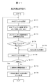
- FIG. 5 is a flowchart of the overall control process 81. That is, the whole process from camera photographing to displaying an AR object on each HMD is shown.
- step S101 log in to participate in the MR experience.
- the login server may be a personal computer directly connected to AP5, or a network server connected to AP5 via a network.
- step S102 the camera 10 starts capturing an image of the physical space.
- the camera shooting may be performed at the timing of executing the entire MR display. For example, the moving image shooting of 30 fps (frame per second) may be continued, and the captured image may be captured at the timing of executing the entire MR display. Is also good.
- S103 is a reference point/movement history processing 82, which detects the position, the shooting direction, and the height of the HMD, and registers them in the reference point/movement history data 91.
- S104 is the synchronization/priority processing 83.
- the shooting object, the background object, and the AR object are synchronized between the plurality of HMDs participating in the MR experience, and the priority processing set for each of the shooting object and the background object is performed. Update to the state of.
- the priority right is to assign an operation right for a specific object to a specific HMD (experienced person), and when the priority right is set, other experiencers cannot edit the object.
- S105 is a display image generation process 87.
- the MR experience person who wears the HMD confirms each of the imaged object, the background object, and the display image of the state in which the priority is updated, and the imaged object processing 84 of S106, the background image processing 85 and S108 of S107 below.
- AR object processing 86 is executed.
- the captured object processing 84 of S106 performs feature extraction of the captured camera captured image, selects feature points, identifies what the real object is from the set of feature points, and sets the captured object data 92 as a captured object. sign up.
- the background object processing 85 of S107 the region including the farthest feature point in the distance data added to the feature points and excluding the photographed object is registered in the background object data 93 as the background object.
- the AR object processing 86 of S108 selects (adds) an AR object to be placed on a shooting object or a background object, and edits a parameter (display parameter) when placing it.
- This processing includes an operation of downloading the AR object data from the network and making a selection by the experience person.
- the data of the selected AR object is registered in the AR object data 94, and the display parameters are registered in the photographic object data 92 and the background object data 93 as linking data.
- S109 is a display image generation process 87, in which a display image of the AR object added or edited in S108 is generated and visually recognized by the MR experienced person in each HMD. It is determined in S110 whether or not to continue. If it is to continue (Yes), the process returns to S102, and if it is not to continue (No), the process ends.
- the plurality of HMDs 1 worn by the plurality of experienced persons 2 are connected to each other, and the imaged object and the background object acquired by each HMD and the data of the virtual object (AR object) associated with the imaged object and the background object are acquired.
- the same real space can be shared by a plurality of experience persons, and each experience person can perform operations such as individually arranging or replacing virtual objects in the real space.
- FIG. 6 is a flowchart of the reference point/movement history processing 82. This processing is executed by the position/direction sensor 12 and the movement detection processing unit 63.
- the MR experienced person 2 wears the HMD 1 and starts camera photographing.
- the position/orientation sensor 12 detects the position of the HMD 1 and the shooting direction of the camera 10, and acquires the data as the position, height, and line-of-sight direction of the experience person.
- the movement history data is represented by the difference from the reference point data. After that, each time the user performs camera shooting while moving in the physical space, the pair of the current position and camera shooting direction is registered in the reference point/movement history data 91 as a movement history.
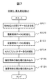
- FIG. 7 is a flowchart of the synchronization/priority processing 83.
- the synchronization process is a process of sharing and updating the data of the imaged object, the background object, and the AR object possessed by each of the plurality of HMDs 1.
- each HMD transmits/receives data to/from another HMD via the communication unit 64, and stores the acquired data in the data flash ROM 69.
- the shooting object data is synchronized.
- the background object data is synchronized.
- the AR object data is synchronized.
- the priority process is a process of reading the priority given to the photographed object and the background object.
- Objects (priorities are set) cannot be edited (associating AR objects) by anyone other than the set MR experience person.
- the priority setting for the imaged object is read.
- the priority setting for the background object is read.
- FIG. 8 is a flowchart of the shooting object process 84. This processing is executed by the feature extraction processing unit 61.
- the captured image is read from the camera 10.
- the feature analysis of the image is performed, for example, the edge is extracted, and the vertex of the edge or the inflection point is extracted as the feature point.
- the type of the object and the like are identified from the set of feature points whose difference is evaluated to be significant.
- the object can be identified by collating with the video database of the external server via the communication unit 64.
- the identified result is registered in the captured object data 92 as a captured object.
- the identified photographed object includes a person, it is transmitted to the display image generation processing 87. This is because there is a high possibility that another MR experienced person is being photographed by the camera. If the other MR experience person determines that it is not necessary as an MR image, it transmits the identification information of this person object to the display image generation processing 87 and requests that it be excluded from the display image. Alternatively, the user himself/herself may determine that the person is another MR experience person from the video image captured by the camera in S131, and may exclude it from the display video image.
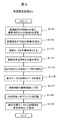
- FIG. 9 is a flowchart of the background object processing 85.
- the feature point having the longest distance is selected from the feature points extracted by the feature extraction processing unit 61.
- a corner of the front wall 4a or the like corresponds.
- a region including the feature point having the farthest distance and not recognized as a photographic object is selected and set as a region A.
- an area in which the distance cannot be detected is selected from the characteristic points extracted by the characteristic extraction processing unit 61 and is set as the area B.
- the areas A and B selected above are set as background objects in the real space.
- difference data from the registered background object data is calculated.
- the background object data acquired from another HMD is synchronized.
- the background object data synchronized with the difference data is integrated.
- the background object is divided into several areas as needed.
- the AR object is arranged in the divided area.
- the cloth object 26 can be attached to the floor 4d.
- the integrated background data and the divided area data are registered as background objects in the background object data 93.
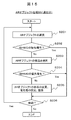
- FIG. 10A and 10B are flowcharts of the AR object process 86.
- a part of the processing procedure is replaced, and either flow may be used. This process is performed interactively by the user while looking at the operation screen.
- one object in which the AR object is to be arranged is selected from the imaged object or the background object (may be a divided area).
- S152 it is confirmed whether the selected object has priority set by another HMD. For that purpose, the result of the priority reading (S125, S126 in FIG. 7) in the synchronization/priority processing 83 is referred to. If the priority is set (Yes), the process proceeds to S156, and if it is not set (No), the process proceeds to S153.
- the priority setting is registered for the selected object. This allows the selected object to be edited (associating the AR object) with priority over other HMDs.
- a background object there are a priority right given to the AR object linked to the entire background object and a priority right given to each divided area of the background object.
- the experiencer who holds the priority right changes the setting in response to a cancellation request from another experiencer (for example, a voice call by the microphone 19).
- the person who has set it may cancel it.
- the priority may be automatically lost when the association of AR objects is released (deleted).
- a specific setting screen is shown in FIG. 12A.
- an AR object to be linked to the selected object is selected.
- AR object selection candidates may be prepared in the HMD 1 in advance, or may be referred to data stored in an external server via the communication unit 64.
- the selected AR object is registered in the AR object data 94.
- display parameters for displaying the AR object are set. This gives the display position, size, and direction of the AR object with respect to the object. That is, it is possible to position the object by giving an offset to the position of a certain feature point of the selected object. For a background object in which the characteristic points are not clear like the area B, an arbitrary point in the area may be selected and the selected point may be used as a pseudo characteristic point.
- the set display parameters are registered in the photographed object data 92 or the background object data 93 as association data of the AR object.
- a concrete edit screen of the AR object is shown in FIG. 12B.
- S156 it is determined whether or not a shooting object or a background object on which the AR object is placed remains. If it remains (Yes), the process returns to S151, and if not (No), the process ends.
- FIG. 10B case 2
- an AR object is first selected, and a shooting object or a background object is assigned to the selected AR object.
- all AR objects to be used are selected. Therefore, the built-in HMD 1 or an external server is referred to.
- the selected AR object is registered in the AR object data 94.
- one of the selected AR objects is selected.
- a shooting object or a background object to which the selected AR object is linked is selected.
- S164 it is confirmed whether the selected object has priority set by another HMD. For that purpose, the result of the priority reading (S125, S126 in FIG. 7) in the synchronization/priority processing 83 is referred to. If the priority is set (Yes), the process proceeds to S167, and if not set (No), the process proceeds to S165.
- step S165 priority registration is set and registered for the selected object. This allows the selected object to be edited with priority over the other HMDs.
- step S166 display parameters (position, size, direction on display) for displaying the AR object are set. The set display parameters are registered in the photographed object data 92 or the background object data 93 as association data of the AR object.
- FIG. 11 is a flowchart of the display video generation processing 87.
- various data registered in the data flash ROM 69 is read to generate a display image of the AR object, which is projected and displayed by the 3D projector 13.
- the AR object to be displayed is selected by referring to the photographed object data 92, the background object data 93, and the AR object data 94.
- the AR object is rotated according to the direction of the HMD 1 (user's line of sight). Further, the AR object is scaled up/down according to the distance to the shooting object (or background object) to be linked.
- the distance relationship (far/near) between the AR object and the real object (photographing object) overlapping with the AR object in the line-of-sight direction is evaluated.
- the distance to the physical object is measured by the distance measuring sensor 11.
- the hidden part or the entire image of the AR object is hidden (for example, the image data is rewritten to 0).
- the 3D projector 13 projects and displays the AR object.
- the process returns to S171 to process the next AR object. If there is no unprocessed AR object (No), the process proceeds to S178.
- step S178 the information of the person object in the imaged object is read.
- the information of the person object is the information transmitted in the photographing object process 84 (S137) and is temporarily stored.
- step S179 a background image is cut out from a background object area that matches the person display area based on the person object information, and the cut out background image is displayed in front of the person (position near the HMD) to cover the person (mask. processing). This prevents other MR experienced persons from appearing in the displayed image.
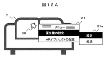
- FIG. 12A shows an operation screen for setting a priority right (S153, S165) to the imaged object.
- the sofa 7, which is a physical object, is recognized as a photographic object, and priority is set for the photographic object.
- the cursor 30 is first placed on the sofa 7 and clicked. This operation pops up the menu small screen 31. From the list presented on the small menu screen 31, click "Set priority”. The clicked item is converted to white characters on a black background.
- This state is shown in FIG. 12A, and in response to this, the priority setting screen 31a appears.
- the experience person selects “setting” or “cancel” of the priority right with the cursor 30, and performs desired setting on the sofa 7.
- FIG. 12B shows an operation screen for editing (S155, S166) the associated AR object.
- S155, S166 the settings of various display parameters are changed for the table object 22 linked to the sofa 7.
- the menu small screen 32 is popped up, and when the "Edit AR object" is clicked, the edit screen 32a appears.
- editing operations such as switching “display/non-display”, changing “display size”, changing “display rotation”, and changing “display layout” are performed.
- the “delete” of the AR object is selected, the linked table object 22 is removed. At this time, when the table object 22 is linked to the sofa 7, the priority right set for the sofa 7 may be canceled.
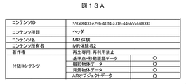
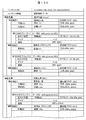
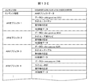
- [Data table] 13A to 13E are diagrams showing examples of various data tables stored in the data flash ROM 69.
- FIG. 13A shows header data.
- the "content ID” at the head of the table is an ID that is common to the table of the shooting object, background object, AR object, etc., which will be described later.
- the "content type” indicates header data
- the "content name” indicates data relating to MR experience.
- a list of data handled by the HMD1 is described in "Accompanying Content”. In addition, information such as “content owner” and “copyright” is included.
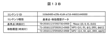
- FIG. 13B shows reference point/movement history data 91.
- content ID indicates that it is the reference point/movement history data.
- the time (T0, T1, T2) and the position/direction are described for the "reference point (PBase)" and the "movement history (MP1, MP2)".
- UTC Universal Time, Coordinated
- difference position (r1, ⁇ 1, ⁇ 1) (distance, horizontal angle, vertical angle)
- difference direction ( ⁇ 1, ⁇ 1) (horizontal angle, vertical angle).
- FIG. 13C shows the photographed object data 92.
- the photographed object data is described by being divided into a reference position (PBase) and a moving position (MP1,...) For each photographing position.
- the imaged object data is synchronized, and the result of collecting the data of a plurality of HMDs is described.
- the photographed object recognized at each photographing position is given a serial number such as “photographed object 1”, “photographed object 2”,... And the identified object names are “window”, “projector”, “sofa”. , Etc. are listed.
- the extracted “feature point 1”, “feature point 2”..., Data of “association AR object”, and a priority flag indicating a priority right setting state are described in each captured object.
- the data of each feature point includes the relative position (distance and direction) with respect to the shooting position of the HMD 1.
- the data of “association AR object” is linked to the AR object data 94 described later, and the AR object (title) designated by the data ID is associated. Further, the “linking position” indicates a feature point at which the AR object is arranged and an offset distance, and the “size” and “rotation” are parameters when the AR object is displayed.
- the shooting objects 1 to 3 are described at the shooting position as the reference position (PBase), the shooting object 1 (window) is associated with the AR object 1, and the shooting object 2 (projector) is associated with the AR object. 2, the photographic object 3 (sofa) is associated with the associated AR object 3.
- the shooting position is the moving position (MP1,).
- the numerical values of the positions and directions of the imaged objects 1 and 2 with respect to the respective characteristic points are slightly different between the reference position (PBase) and the moving position (MP1). This is because even if the imaged objects 1 and 2 do not move in the physical space, the values change depending on the movement of the HMD 1. Further, when a new imaged object is recognized at the moving position, it is added to the table.
- each shooting object is given a priority flag that indicates the priority setting state.
- the priority flag is composed of a plurality of digits, and the first digit is "1" when the photographer (data provider) of the object has set the priority.
- the remaining digits represent the MR experiencer who has priority, and the relationship between the digit value and the MR experiencer is given at login.
- the priority is set when a certain MR experience person associates an AR object with a shooting object and does not want another MR experience person to change the associated AR object.
- FIG. 13D shows the background object data 93.
- the background object data is divided for each shooting position, and is described separately for the reference position (PBase) and the moving position (MP1,... ).
- the background object data is also synchronized, which is the result of aggregating the background object data of a plurality of HMDs.
- feature point 1 “feature point 1”, “feature point 2”,... are described, and these feature points may include pseudo feature points designated by the user.
- the “correlated AR object” is described, which includes the data ID of the AR object to be linked and the priority flag.
- the background object data has bit map data corresponding to the coordinates of the image of the virtual 360° camera centered on the reference point so that its position and shape can be grasped.
- the background object is further divided into areas, it has divided area data.
- the divided area data includes area division information such as feature points, priority information, and 3D image data of a cross object that covers the divided area.
- FIG. 13E shows the AR object data 94.
- the AR object data is, for example, data downloaded from a server on the network, and a serial number is assigned to each AR object.
- a data ID for identification is given to each AR object data, and is linked to the above-described photographic object data and background object data via this.
- a title and a copyright are described as items, and 3D image data is stored.
- a display image is generated using this 3D image data.
- a plurality of MR display devices worn by a plurality of experienced persons are connected to each other, and an imaged object or a background object acquired by each device, and a virtual object linked to this.
- Data of (AR object) can be transmitted/received and shared.
- the same real space can be shared by a plurality of experience persons, and each experience person can perform operations such as individually arranging or replacing virtual objects in the real space.
- a priority right for assigning an operation authority for a specific object to a specific HMD is set, so that, for example, a plurality of workers can use the same space in the same space. Space can be shared and smooth work can be efficiently performed.
- FIG. 14 is a diagram illustrating an example of the MR space according to the second embodiment.
- the same elements as those in the MR space shown in FIG. 4A of the first embodiment are designated by the same reference numerals, and duplicate description will be omitted.
- the difference from the MR space of FIG. 4A is that the projector 8 is removed, the cross object 26 is not provided, and the TV object 21 which is an AR object is composed of three parts 21a, 21b, and 21c.
- 21a is a flat panel
- 21b is a pillar
- 21c is a pedestal.
- the colors and forms of the three parts can be individually selected, and different MR users can set the colors and forms of the parts.
- FIG. 15 shows a flowchart of the AR object process 86 (addition) in the second embodiment.
- the AR object is already associated with the flow of FIG. 10A or 10B of the first embodiment.
- the AR object associated is composed of a plurality of parts, and a part of the parts is edited (changed).
- one AR object is selected.
- the priority is set from another HMD to the imaged object or the background object that is associated with the selected AR object.
- the priority is applied to the entire AR object, and the process proceeds to S206. If the priority is not set (No), the process proceeds to S203.
- the part to be changed in the AR object is selected.
- S205 the parts of the AR object are edited (changed), the priority is set, and registered in the data table.
- S206 it is determined whether or not there is an AR object whose component is to be changed. If there is (AR), the process returns to S201, and if there is no (NO), the process ends.
- FIG. 16A and 16B are examples of the data table according to the second embodiment.
- FIG. 16A shows a data table of captured object data
- FIG. 16B shows a data table of AR object data.
- the AR object 2 linked to the projector of the imaged object 2 in FIG. 16A is composed of a plurality of parts 1 to 3. A detailed classification of the data ID is described for each part, and a priority flag indicating editing authority by different MR experiencers is given to each part.
- 3D image data of three parts corresponding to the parts 1 to 3, that is, a panel, a pillar, and a pedestal are stored.
- the same effect as that of the first embodiment can be obtained, and the AR object can be configured by a plurality of parts, and different priority can be set for each part.
- one AR object can be edited by a plurality of MR users to express various combinations of MR spaces.
- MR network system a configuration in which a plurality of MR display devices (HMDs) are connected to a network and the MR processing performed by each HMD is performed by a server connected to the network.
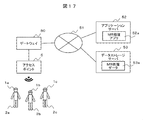
- FIG. 17 is a diagram illustrating the configuration of the MR network system according to the third embodiment.
- a plurality of MR display devices (HMDs) 1a, 1b, 1c are attached to MR experienced persons 2a, 2b, 2c, respectively, and each HMD 1a, 1b, 1c passes through an access point (AP) 5 such as a wireless LAN and a gateway 50.
- AP access point
- An application server 52 and a data storage server 53 are also connected to the network 51.
- the application server 52 includes an MR processing application for synthesizing shot images of a plurality of users and arranging AR objects.
- the data storage server 53 stores the data of the AR object and the photographed object, the combined video data of the room, the position information when the AR object is arranged, and the like, and each experience person can read it.
- each HMD 1a, 1b, 1c the processing programs 81 to 87 stored in the program flash ROM 68 and the data table 91 stored in the data flash ROM 69 in the functional block shown in FIG. To 94 can be omitted or simplified.
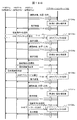
- FIG. 18A and FIG. 18B are sequence diagrams of the MR network system, and show data transmission/reception between each HMD 1a, 1b, 1c (each MR experienced person 2a, 2b, 2c) and the application server 52.
- FIG. 18A is a diagram showing the entire sequence.
- the same processes as those in FIG. 5 of the first embodiment are denoted by the same reference numerals, and are constituted by the login process of S101 to the display image generation process of S109.
- a pair of basic communication sequence of request and response is used, but it is omitted here to avoid complication of description. The outline will be described below in the order of processing.
- S101 The MR experienced persons 2a to 2c log in to the application server 52 to participate in the MR experience.
- S102 The MR experienced persons 2a to 2c photograph a part of the physical space with the camera and send the photographed video data to the application server 52.
- S103 Further, the MR experienced persons 2a to 2c transmit position and direction data to the application server 52 as reference point/movement history data.
- S104 The application server 52 aggregates the data of all MR experienced persons, synthesizes the images, and synchronizes them.
- S105 The application server 52 generates and transmits each display image of the MR experienced person (S105).
- S106 The application server 52 processes the photographed object.
- S107 The application server 52 processes the background object. At that time, the area experience and the cross object instruction are received from the MR experienced person.
- the application server 52 processes the AR object. At that time, the data of the AR object selected for the designation of the photographed object or the background object selected by the MR experience person and the linking is accepted. S109: The application server 52 reflects these execution results to generate a display image and sends it to the MR experience person. Further, the data generated when the application is executed is stored in the data storage server 53.
- the MR experienced persons 2a to 2c realize the MR experience via the application server 52 by repeating a series of sequences except the login of S101 as a basic sequence.
- FIG. 18B is a diagram showing details of the sequence of FIG. 18A.
- S104 synchronization/priority process
- S108 AR object process
- S105 display image generation processing
- S106 captured object processing
- S107 background object processing
- T11 The HMDs 1a to 1c transmit the captured images, the HMD position, and the capturing direction to the application server 52.
- the transmission timing may be in accordance with a transmission request from the application server 52, or may be captured by the application server 52 at a convenient timing from captured images continuously transmitted.
- T12 The application server 52 performs the synchronization/priority process S104a, and transmits the display image of the AR object or the like whose display position is updated corresponding to the movement of the HMD to each of the HMDs 1a to 1c.
- T13 At this time, when the HMD 1a (MR experiencer 2a) having the priority of the shooting object A wants to link the AR object ⁇ to the shooting object A, the selection of the AR object ⁇ to be linked with the selection information of the shooting object A.
- the information is transmitted to the application server 52.
- T14 The application server 52 executes the AR object processing S108a, and transmits the display image of the AR object ⁇ based on the setting information of the AR object ⁇ to the HMD 1a and the other HMDs 1b and 1c.
- T15 From the HMDs 1a to 1c, the new photographed image, the position of the HMD, and the photographing direction are transmitted to the application server 52.
- T16 The application server 52 performs the synchronization/priority processing S104b, and transmits the display video including the arrangement of the AR object ⁇ to each of the HMDs 1a to 1c.
- T17 After that, when the HMD 1b (MR experiencer 2b) who does not have the priority of the shooting object A wants to associate a different AR object ⁇ to the shooting object A, a request for canceling the priority given to the shooting object A is issued. , HMD 1a, 1c and the application server 52. When the HMD 1a (MR experience person 2a) having the priority right accepts the priority release request from the HMD 1b, the priority is released and the HMD 1b is given the priority.
- HMD 1a MR experience person 2a
- T18 The HMD 1b transmits to the application server 52 the selection information of the AR object ⁇ associated with the photographic object A.
- T19 The application server 52 executes the AR object processing S108b, and transmits the display image of the AR object based on the setting information of the AR object ⁇ to the HMDs 1a to 1c.
- T20 From the HMDs 1a to 1c, the new photographed image, the position of the HMD, and the photographing direction are transmitted to the application server 52.
- T21 The application server 52 performs the synchronization/priority process S104c, and transmits the display image including the arrangement of the AR object ⁇ to each of the HMDs 1a to 1c.
- T22 At this time, it is assumed that the HMD 1c (MR experiencer 2c) selects a different imaged object C and transmits a request to select the AR object ⁇ , and this is permitted.
- the HMD 1c transmits the selection information of the AR object ⁇ to be given.
- T23 The application server 52 executes the AR object processing S108c, and transmits the display image of the AR object based on the setting information of the AR object ⁇ to the HMDs 1a to 1c.
- the HMDs 1a to 1c share a shooting object existing in the same real space, add an AR object that is a virtual object to the real space, and display an image of the added AR object. It can be visually recognized as a display image generated according to each position.
- the MR network system according to the third embodiment has the same effect as that of the first embodiment and is characterized in that resources such as application servers and data servers on the network can be utilized. This has the effect of reducing the load on the MR display device, contributing to downsizing and cost reduction of the MR display device, and facilitating the handling even when the number of MR experienced persons increases.
- Example 4 an MR display device equipped with a 3D camera for shooting and distance measurement will be described.
- FIG. 19 is a diagram showing an external configuration of the MR display device 1′ according to the fourth embodiment. Constituent elements having the same functions as those of the MR display device 1 shown in the first embodiment (FIG. 2) are designated by the same reference numerals, and a duplicate description will be omitted.
- the MR display device 1 ′ includes 3D (3D) cameras 40 a and 40 b and a flat display 41.
- the 3D cameras 40a and 40b are obtained by replacing the camera 10 and the distance measuring sensor 11 in the first embodiment, and not only obtain the image captured by the camera, but also the difference between the image of the left visual line obtained by 40a and the image of the right visual line obtained by 40b. It is also possible to measure the distance of a real object in a camera image.
- the flat display 41 replaces the 3D projector 13 and the transmissive screen 14 in the first embodiment, and displays the images captured by the 3D cameras 40a and 40b and the AR object image by the controller 16 and displays them. At this time, the image of the left line of sight and the image of the right line of sight are alternately displayed, and the 3D image is displayed in synchronization with the glasses with shutter 15.
- a general-purpose device such as a smartphone may be used for the flat display 41. At this time, the function of the controller 16 can be executed by the control device incorporated in the smartphone.
- FIG. 20 is a block diagram showing the functional configuration of the MR display device 1'.
- the blocks having the same functions as the blocks shown in the first embodiment (FIG. 3) are designated by the same reference numerals, and the duplicated description will be omitted.
- the blocks different from the first embodiment are the 3D cameras 40a and 40b, the flat display 41, the video composition processing unit 42, the feature extraction processing unit 61' in the controller 16, and the distance calculation processing unit 62'.
- the feature extraction processing unit 61' extracts feature points from the images of the 3D cameras 40a and 40b, and identifies the physical object shown in the image captured by the camera from the feature points.
- the distance calculation unit 62' measures the distance of the real object in the camera image based on the difference between the images of the left-eye/right-eye line of sight obtained by the 3D cameras 40a and 40b.
- the combining processing unit 42 combines the images captured by the 3D cameras 40a and 40b and the AR object image, and the flat display 41 displays the combined image.
- a general-purpose device such as a smartphone including a flat display.
- the present invention is not limited to these, and a part of the constitution of a certain embodiment may be replaced with the constitution of another embodiment, or the constitution of another embodiment may be changed. It is also possible to add.
- MR display device HMD
- 2a to 2c MR experienced person
- 3a to 3c Camera photographing angle of view
- 4 Real object (background object)
- 5 Access point (AP)
- 6 to 8 real object (imaging object)
- 10 camera
- 11 distance measuring sensor
- 12 position/orientation sensor
- 13 3D projector
- 14 transmissive screen
- 15 glasses with shutters.
Landscapes
- Engineering & Computer Science (AREA)
- Theoretical Computer Science (AREA)
- Physics & Mathematics (AREA)
- General Physics & Mathematics (AREA)
- General Engineering & Computer Science (AREA)
- Human Computer Interaction (AREA)
- Computer Graphics (AREA)
- Computer Hardware Design (AREA)
- Software Systems (AREA)
- Multimedia (AREA)
- Computer Vision & Pattern Recognition (AREA)
- Signal Processing (AREA)
- Architecture (AREA)
- Geometry (AREA)
- Computer Networks & Wireless Communication (AREA)
- Processing Or Creating Images (AREA)
- User Interface Of Digital Computer (AREA)
- Information Transfer Between Computers (AREA)
Abstract
MR表示装置1は、他の体験者が装着する他のMR表示装置と接続して現実映像と仮想物体の映像を互いに共有する構成であって、カメラ10で撮影した現実映像から現実物体を認識し、体験者2の操作に基づき、現実物体に所定の仮想物体を紐付けするコントローラ16と、紐付けされた仮想物体の映像を表示する表示部13と、を備える。コントローラは、通信部64を介して他のMR表示装置が生成した現実物体の認識結果及び紐付けした仮想物体のデータを取得し、取得したデータと自身のデータとを合成して、合成した映像を表示部に表示するとともに、体験者の操作に基づき、表示部に表示された映像に対し、現実物体に紐付けする仮想物体の編集が可能である。
Description
本発明は、現実空間と仮想物体とを合成した複合現実(MR:Mixed Reality)空間を体験する複合現実表示装置および複合現実表示方法に関する。特に、複数のMR体験者がMR体験を共有するのに好適な技術に係る。
現実空間やカメラで撮影する現実映像にCG(Computer Graphics)等で作成した仮想物体である拡張現実(AR:Augmented Reality)オブジェクトを付与することが、ゲームや保守作業等のコンテンツに用いられている。ARオブジェクトを付与するために、ARトリガーあるいはマーカーと呼ばれる映像をカメラで背景と同時に撮影して、ARトリガーにより紐付けするARオブジェクトを現実映像に合成する。特にMR体験では、カメラとディスプレイとが一体化されたヘッドマウントディスプレイ(HMD)を用いて、HMDに搭載したカメラで撮影した現実空間の映像を元に、HMDの位置及び姿勢に応じて生成するARオブジェクトを、仮想物体の映像として現実空間に重畳表示する。
これに関し特許文献1では、複数の人がMR体験を共有するために、HMDに加えて、タブレットなどの携帯情報端末を組み合わせたMRシステムが記載されている。このMRシステムでは、HMDに表示しているMR映像をタブレットにも表示させ、タブレットのユーザは、共有しているMR映像中の仮想物体を指定し、指定した結果をMR映像に反映させことができる、と記載されている。
しかしながら特許文献1の方法では、携帯情報端末のユーザは仮想物体を指定できるのみであり、仮想物体を現実空間に配置したり、置換したりする操作はできない。また、HMDの現実空間は共有できるが、携帯情報端末のユーザ自身の現実空間は共有できない。
このように特許文献1では、MR空間を複数の人が体験する場合において、HMD装着者を除く他の体験者は、仮想物体を現実空間に配置あるいは置換するという操作はできなく、さらに他の体験者の現実空間を共有できないという課題がある。
本発明は上記の点を鑑みてなされたものであり、その目的は、MR空間を複数の人が体験する場合において、複数の体験者が、仮想物体を現実空間に同時に配置あるいは置換する等の操作が可能で、かつ複数の体験者の現実空間が共有可能である複合現実表示装置および複合現実表示方法を提供することにある。
上記課題を解決するために、本発明の複合現実表示装置は、他の体験者が装着する他の複合現実表示装置と接続して現実映像と仮想物体の映像を互いに共有する構成であって、現実映像を撮影するカメラと、カメラで撮影した現実映像から現実物体を認識し、体験者の操作に基づき、認識した現実物体に所定の仮想物体を紐付けするコントローラと、紐付けされた仮想物体の映像を表示する表示部と、現実物体と紐付けされた仮想物体のデータを保存するメモリと、他の複合現実表示装置と接続しデータを送受信する通信部と、を備える。前記コントローラは、前記通信部を介して他の複合現実表示装置が生成した現実物体の認識結果及び紐付けした仮想物体のデータを取得し、取得したデータと前記メモリに保存されたデータとを合成して、合成した映像を前記表示部に表示するとともに、体験者の操作に基づき、前記表示部に表示された映像に対し、現実物体に紐付けする仮想物体の編集が可能であることを特徴とする。
さらに本発明の複合現実表示方法は、複数の複合現実表示装置で現実映像を撮影するステップと、撮影された現実映像を連結して現実物体を認識するステップと、各体験者の操作に基づき選択された仮想物体を現実物体に紐付けして合成するステップと、各複合現実表示装置にて、連結された現実物体と紐付けされた仮想物体の合成データをもとに共通の映像を表示するステップと、表示された映像に対し、各複合現実表示装置の体験者が、現実物体に紐付けする仮想物体の編集を行うステップと、を備える。
本発明によれば、MR空間を複数の人が体験する場合において、複数の体験者が、仮想物体を現実空間に配置あるいは置換等の操作が可能となり、かつ複数の体験者の現実空間を共有することが可能となる。
以下、図面を参照しながら、本発明の実施例について説明する。以下では、複合現実表示装置をMR表示装置、またはHMDとも呼ぶ。
実施例1では、複数のMR表示装置を相互に接続し、装置間でデータのやり取りを行うシステムについて説明する。
[MR表示システム]
図1Aは、複数のMR表示装置を適用する現実空間の例を示す図である。このシステムでは、3台のMR表示装置(HMD)1a,1b,1cを有し、MR空間の複数の体験者2a,2b,2cは、それぞれの頭部にHMD1a,1b,1cを装着している。後述するように各HMDは、カメラ、測距センサ、ディスプレイ、通信部、位置・方位センサを内蔵し、カメラで現実空間を撮影するとともに、ディスプレイに表示されるMR映像により、体験者はMR映像を視認する。HMD1a,1b,1cが内蔵するカメラの撮影画角を符号3a,3b,3cで示す。また、HMD1a,1b,1cの間で通信するために、無線LANなどのアクセスポイント(AP)5を設けている。体験者(HMD)の位置と視線方向が異なるので、それぞれが視認する現実空間は異なるが、HMD間で通信することで、共通のMR映像を体験することができる。
図1Aは、複数のMR表示装置を適用する現実空間の例を示す図である。このシステムでは、3台のMR表示装置(HMD)1a,1b,1cを有し、MR空間の複数の体験者2a,2b,2cは、それぞれの頭部にHMD1a,1b,1cを装着している。後述するように各HMDは、カメラ、測距センサ、ディスプレイ、通信部、位置・方位センサを内蔵し、カメラで現実空間を撮影するとともに、ディスプレイに表示されるMR映像により、体験者はMR映像を視認する。HMD1a,1b,1cが内蔵するカメラの撮影画角を符号3a,3b,3cで示す。また、HMD1a,1b,1cの間で通信するために、無線LANなどのアクセスポイント(AP)5を設けている。体験者(HMD)の位置と視線方向が異なるので、それぞれが視認する現実空間は異なるが、HMD間で通信することで、共通のMR映像を体験することができる。
現実空間は、部屋の壁4a、4b、4cと床4dとが背景となる。これに現実物体として、窓6、ソファ7、プロジェクタ8と、プロジェクタ8の投射画面8aが置かれている。MR体験者2a,2b,2cは、この現実空間内でMR体験をする。具体的には、複数の作業者(MR体験者)により室内のインテリアのレイアウトを行う場面を一例として想定している。
MR体験を共有化するため、体験者2a,2b,2cは視線方向(カメラの撮影方向)と、位置及び高さの初期設定(座標合わせ)を行う。例えば、カメラで窓6を撮影し、窓6の隅6b、6cがHMDのディスプレイ画面の中央6aに対して対称となるようにし、撮影方向の基準を定める。そのままの状態で、窓6から所定の距離の位置に移動し基準位置とする。これら撮影方向、位置に加え、体験者の身長に依るHMDの高さを基準点として登録する。基準点の登録は、体験者2a,2b,2cがそれぞれ行うが、体験者2の高さを基準として、体験者2b、2cの高さの差を補正しても良い。基準点登録後の体験者2a,2b,2cの移動は、位置・方位センサにて検知し、移動履歴データとして記録する。これにより各体験者の位置データを共通の座標系で表わすことができる。
なお、初期化の方法は上記の方法に限定されるものではなく、GPSセンサ、方位センタを用いる方法であっても良く、MR空間の体験者間で基準点を共有できるものであれば良い。
HMDのカメラで撮影できる画角3a,3b,3cは、現実空間の一部でしかない。本システムでは、HMD1a,1b,1cにより取得した撮影画角3a,3b,3cの撮影映像を合成し、連結した現実空間の映像(背景映像)を生成する。その際、撮影した時の各HMDの位置、方角、高さを、基準点から撮影したものとして視点変換して合成する。背景映像の連結は、体験者2a,2b,2cの移動のたびに繰り返し、領域が重なる部分は、新しい背景映像で更新する。
図1Bは、背景映像を連結した状態を示す図である。HMD1aで撮影する範囲(図1Aの撮影画角)3a、HMD1bで撮影する範囲3b、HMD1cで撮影する範囲3cは、異なる撮影位置での背景映像である。これらの映像を基準点から撮影した映像に視点変換し、基準点を中心とする360度の全周空間にマッピングして、連結した背景映像とする。
360度の全周空間は、撮影範囲3a,3b,3cで全ての空間がカバーされる訳でもない。そこで各HMD1a,1b,1c(各体験者2a,2b,2c)が移動し、次の時刻Tで新たな撮影範囲3aT,3bT,3cTで撮影する。そして、撮影範囲3aT,3bT,3cTでの映像を視点変換して、連結した背景映像に追加し、背景映像の空間を広げて行く。空間を拡大するときは、特に壁の境界や床と壁の接線、窓のフレームのような特徴点を重ねて広げると連結しやすい。重複する背景映像の部分は、時間的に新しい背景映像の部分に置き換え、背景映像を更新する。
なお、背景映像の連結処理に関して言えば、HMDの撮影映像に代えて、後述する背景物体データを取得した後で、背景物体データを連結させるようにしても良い。さらに、各々のHMDで撮影映像から撮影物体データおよび背景物体データを取得し、各々のHMDで取得した撮影物体データを共有するとともに、背景物体データを連結させるようにしても良い。
このように、複数のHMD(複数の体験者)が取得した背景映像の連結処理を行うことで、1台のHMD(1人の体験者)では認識できない背景を合成することができる。具体的には、図1Aや図1Bにおいて、体験者2bのカメラの画角3bでは、ソファ7を捉えることができず、体験者2cのカメラの画角3cでは、プロジェクタ8を捉えることができない。しかし、各体験者のカメラ映像を連結し、連結された背景映像を各体験者で共有することで、ソファ7やプロジェクタ8の存在が認識され、認識した情報は後述する撮影物体として、複数の体験者2a,2b,2cで共有することができる。
[MR表示装置]
図2は、実施例1に係るMR表示装置の外観構成を示す図である。MR表示装置(HMD)1(1a~1c)は、カメラ10、測距センサ11、位置・方位センサ12、3Dプロジェクタ13、透過型スクリーン14、シャッタ付きメガネ15、コントローラ16、スピーカ17a,17b、ホルダ18a,18b、マイク19を備える。MRの体験者2は、ホルダ18a,18bで、HMD1を自身の頭部に装着する。
図2は、実施例1に係るMR表示装置の外観構成を示す図である。MR表示装置(HMD)1(1a~1c)は、カメラ10、測距センサ11、位置・方位センサ12、3Dプロジェクタ13、透過型スクリーン14、シャッタ付きメガネ15、コントローラ16、スピーカ17a,17b、ホルダ18a,18b、マイク19を備える。MRの体験者2は、ホルダ18a,18bで、HMD1を自身の頭部に装着する。
カメラ10は、頭部前方(体験者の視線方向)を撮影するように取り付けられており、測距センサ11は、カメラ10の撮影映像が捉える現実物体との距離を測定する。位置・方位センサ12は、ジャイロ、位置、方位センサ等で構成され、体験者の位置と視線方向を検知する。
測距センサ11は、TOF(Time of Flight)方式のように2次元的に光線を照射して距離を計測するものでも良いし、輪郭等の特徴点に対してステレオカメラのような方式で距離を算出するものでも良く、カメラ撮影映像に対応してカメラと現実物体との距離を測定できるものであれば良い。
3Dプロジェクタ13は、3Dの仮想物体(ARオブジェクト)を、左目で確認する映像と右目で確認する映像とを交互に透過型スクリーン14に投射して表示する。シャッタ付メガネ15は、これに同期して左右交互に映像を透過させる。体験者2は、前方の風景や現実物体を透過型スクリーン14を通して見ることができるとともに、これに重畳して3Dプロジェクタ13で投射された3Dの仮想物体を透過型スクリーン14上で視認することができる。
コントローラ16は、カメラ10の撮影映像、測距センサ11の距離データ、位置・方位センサ12の位置・方位データを取り込み、内部のメモリやCPUに供給する。また、3Dプロジェクタ13で投射する映像やスピーカ17a,17bに出力する音声を作成する。さらにシャッタ付メガネ15の駆動信号を生成し、3Dプロジェクタ13で投射するARオブジェクトの映像に同期して、左右メガネの透過を切り替えて、体験者に3D映像を提供する。
またコントローラ16は、MR体験者2とのユーザインターフェースを含む。コントローラ16をスマートフォンのようなデバイスで実現する場合には、ユーザインターフェースはタッチセンサを内蔵したパネルを利用できる。
図3は、MR表示装置1の機能構成を示すブロック図である。図2と同一のものには同一の符号を付している。HMD1のコントローラ16の内部(破線で示す)には、特徴抽出処理部61、距離算出処理部62、移動検知処理部63、通信部64、CPU65、RAM66、画像RAM67、プログラムフラッシュROM(P-FROM)68、データフラッシュROM(D-FROM)69と、さらにユーザ操作入力部60を備える。
特徴抽出処理部61は、カメラ10からの撮影映像に対し、現実物体の輪郭(エッジ)を抽出し、輪郭の変曲点や頂点を特徴点とする処理を行う。距離算出処理部62は、測距センサ11での計測データをもとに、特徴点までの距離を算出する。移動検知処理部63は、位置・方位センサ12からの計測データをもとに、HMD1の位置と移動量、及びカメラ10の撮影方向を求め、すなわちこれが、体験者2の位置と移動量、視線方向となる。
通信部64は、HMD1をアクセスポイント5に接続し、他のHMD1との間でデータのやり取りを行う。あるいは、外部ネットワークに接続し、外部ネットワークに繋がるサーバ等によって、HMD1の処理の一部を担わせることができる。
プログラムフラッシュROM68には、各種の処理プログラムが格納されている。これには、全体制御処理81、基準点・移動履歴処理82、同期化・優先権処理83、撮影物体処理84、背景物体処理85、ARオブジェクト処理86、表示映像生成処理87が含まれる。これらの処理プログラムは、RAM66に展開してCPU65で実行する。
さらにデータフラッシュROM69には、これら処理プログラムを実行する過程及び結果で発生するデータが格納される。これには、基準点・移動履歴データ91、撮影物体データ92、背景物体データ93、ARオブジェクトデータ94が含まれる。これより、体験者がMR空間を再現して体験したい場合に、これらの格納しているデータを読み出すことによって実現可能となる。
なお、プログラムフラッシュROM68とデータフラッシュROM69は、図示したように別々のメモリ媒体で構成しても良いし、1つのメモリ媒体で構成しても良い。さらには2つ以上のメモリ媒体であっても良く、フラッシュROM以外の不揮発性のメモリ媒体であっても良い。またデータフラッシュROM69は、ネットワーク上にあるデータサーバに置いても良い。
表示映像生成処理87で生成した映像データは、画像RAM67に格納し、画像RAM67から読み出して3Dプロジェクタ13で投射する。また、ユーザ操作入力部60ではタッチセンサによりユーザ入力を受け付け、3Dプロジェクタ13で透過型スクリーン14に制御メニュー映像を投射し、HMD1を制御する。
[MR空間]
次に、MR表示装置1の各機能ブロックの動作、すなわち現実空間にARオブジェクトを配置してMR空間を作成する処理を具体的に説明する。
次に、MR表示装置1の各機能ブロックの動作、すなわち現実空間にARオブジェクトを配置してMR空間を作成する処理を具体的に説明する。
まず、図1Aに示した現実空間において、現実物体を撮影物体または背景物体として認識し、登録する。現実空間としての部屋は、正面壁4a、左側壁4b、右側壁4c、床4dで囲われており、窓6、ソファ7、プロジェクタ8が存在する。
複数のHMD1のカメラ10はこれらの現実物体を撮影し、特徴抽出処理部61は現実物体の輪郭(エッジ)を抽出し、輪郭の変曲点や頂点を特徴点とする処理を行う。輪郭を構成する特徴点の集合は、CPU65に送られ、物体が何であるかを識別する。その際、通信部64を介して外部のサーバの映像データベースと照合して、物体の識別を行ってもよい。
一方、測距センサ11と距離算出処理部62は、部屋内の各物体までの距離を算出し、現実空間内の見取り図を作成する。そして、特徴抽出処理部61で抽出した特徴点には、距離算出処理部62で算出した距離データを組み合わせる。さらに基準点・移動履歴処理82では、位置・方位センサ12と移動検知処理部63により、HMD1がどの位置(座標)でどの方向を向いた状態で撮影したものかを記録しておく。
識別された現実物体は、撮影物体処理84および背景物体処理85により、「撮影物体」または「背景物体」に区別して登録する。撮影物体は、特有の物体形状を有し距離データが相対的に近くに位置するもので、本例では、窓6、ソファ7、プロジェクタ8が登録される。一方、背景物体は、例えば平面以外の特有の物体形状を有していなかったり、距離データが最遠点を含んだりするもので、本例では、正面壁4a、左側壁4b、右側壁4c、床4dを背景物体として登録する。つまり、背景物体は、カメラ撮影映像の背景を構成する物体である。
図4Aは、現実空間にARオブジェクトを配置したMR空間の例を示す図である。図1Aに示した現実空間と同一の物体には同一の符号を付しており、新たに仮想物体としてARオブジェクト21~26を配置している。HMD1a~1cを装着した各体験者2a~2cは、このようなMR空間を体験することができる。
各ARオブジェクト21~26は、特定の現実物体(撮影物体または背景物体)の位置に合わせて(つまり紐付けされて)配置される。ARオブジェクトの配置は、各体験者2の操作に基づくARオブジェクト処理86により決定される。この処理を「紐付け処理」ともいう。すなわち紐付け処理では、図1Bのカメラ映像から作成した現実空間の見取り図をベースとし、各ARオブジェクトを配置する座標を決める。この時、ARオブジェクトの配置情報(紐付け情報)では、どの物体に関連付けるかを指定するだけでなく、物体のどの部分に配置するか指定するため、物体の特定の特徴点にオフセット距離を与えて位置決めする。
本例の場合、TVオブジェクト21は、撮影物体であるプロジェクタ8を置換するように配置される。テーブルオブジェクト22と花瓶オブジェクト23はソファ7に紐付けされ、ソファ7の前面に位置するような距離と方向のオフセットが与えられる。さらに花瓶オブジェクト23には、花瓶が丁度テーブル上に置かれた状態になるよう高さ方向のオフセットが指定される。カーテンオブジェクト24は窓6に紐付けされ、窓6の特定の特徴点にオフセット距離を与えて配置される。時計オブジェクト25は、背景物体である壁4に紐付けられているが、正面壁4aの任意の点を擬似特徴点として定め、その上に配置している。
クロスオブジェクト26は、背景物体を布で覆いかぶせた効果を得る3Dオブジェクトである。本例では、背景物体である床4d部分の領域に適用し、床4dに絨毯を敷き詰めたような加工をシミュレーションすることができる。この時、TVオブジェクト21で置換されるプロジェクタ8もクロスオブジェクト26で覆われるが、プロジェクタ8の存在により、クロスオブジェクト26は盛り上がり、皺26aができている。
図4Bは、クロスオブジェクト26の生成法を説明する図である。クロスオブジェクト26で覆われるプロジェクタ8までの距離情報を用いて、プロジェクタ8に接する位置にポリゴン群26bを配置し、プロジェクタ8を覆い隠す。床部分4dの平面領域及びポリゴン群26bに、3Dコンピュータグラフィックスのレンダリング技法でテクスチャを貼り付け、クロスオブジェクト26を生成する。
[MR表示装置の処理フロー]
次に、MR表示装置(HMD)1の行う各種の処理フローについて説明する。すなわちCPU65は、プログラムフラッシュROM68に格納される以下のプログラムに従い、処理を実行する。
次に、MR表示装置(HMD)1の行う各種の処理フローについて説明する。すなわちCPU65は、プログラムフラッシュROM68に格納される以下のプログラムに従い、処理を実行する。
図5は、全体制御処理81のフローチャートである。すなわち、各HMDにおいてカメラ撮影からARオブジェクトを表示するまでの全体の工程を示す。
S101でMR体験への参加のためにログインする。ログインサーバは、AP5に直接繋がっているパソコンであっても良いし、AP5からネットワークを介して繋がるネットワークサーバであっても良い。
S102でカメラ10による現実空間の撮影を開始する。カメラ撮影は、MR表示全体を実行するタイミングで行っても良いし、例えば30fps(frame per second)の動画撮影を継続していて、MR表示全体を実行するタイミングで撮影映像をキャプチャするようにしても良い。
S102でカメラ10による現実空間の撮影を開始する。カメラ撮影は、MR表示全体を実行するタイミングで行っても良いし、例えば30fps(frame per second)の動画撮影を継続していて、MR表示全体を実行するタイミングで撮影映像をキャプチャするようにしても良い。
S103は基準点・移動履歴処理82であり、HMDの位置、撮影方向及び高さを検知し、基準点・移動履歴データ91に登録する。
S104は同期化・優先権処理83である。該処理83では、MR体験に参加している複数のHMD間で、撮影物体、背景物体、ARオブジェクトの同期化と、各々の撮影物体、背景物体に設定される優先権の処理を行い、最新の状態に更新する。優先権とは、特定の物体に対する操作権限を、特定のHMD(体験者)に割り当てることであり、優先権が設定されている場合、他の体験者はその物体に対する編集等ができない。
S104は同期化・優先権処理83である。該処理83では、MR体験に参加している複数のHMD間で、撮影物体、背景物体、ARオブジェクトの同期化と、各々の撮影物体、背景物体に設定される優先権の処理を行い、最新の状態に更新する。優先権とは、特定の物体に対する操作権限を、特定のHMD(体験者)に割り当てることであり、優先権が設定されている場合、他の体験者はその物体に対する編集等ができない。
S105は、表示映像生成の処理87である。HMDを装着したMR体験者は、各々の撮影物体と背景物体、及び優先権を最新化した状態の表示映像を確認しながら、以下のS106の撮影物体処理84、S107の背景映像処理85、S108のARオブジェクト処理86を実行する。
S106の撮影物体処理84は、キャプチャしたカメラ撮影映像の特徴抽出を行い、特徴点を選び、特徴点の集合に対して、現実物体が何であるかを識別し、撮影物体として撮影物体データ92に登録する。
S107の背景物体処理85は、特徴点に付与される距離データで最遠点にある特徴点を含み、撮影物体を除く領域を背景物体として背景物体データ93に登録する。
S107の背景物体処理85は、特徴点に付与される距離データで最遠点にある特徴点を含み、撮影物体を除く領域を背景物体として背景物体データ93に登録する。
S108のARオブジェクト処理86は、撮影物体や背景物体に配置するARオブジェクトを選択(追加)し、また配置するときのパラメータ(表示パラメータ)を編集する。この処理では、ARオブジェクトのデータをネットワークからダウンロードし、体験者が選択する操作が含まれる。選択したARオブジェクトのデータをARオブジェクトデータ94に登録し、表示パラメータは紐付けデータとして、撮影物体データ92と背景物体データ93に登録する。
S109は表示映像生成処理87であり、S108にて追加もしくは編集したARオブジェクトの表示映像を生成し、各HMDにてMR体験者が視認する。
S110で継続するかの判断を行い、継続する場合(Yes)ではS102に戻り、継続しない場合(No)には終了する。
S110で継続するかの判断を行い、継続する場合(Yes)ではS102に戻り、継続しない場合(No)には終了する。
このように本実施例では、複数の体験者2が装着した複数のHMD1を相互に接続し、各HMDで取得した撮像物体や背景物体、及びこれに紐付けした仮想物体(ARオブジェクト)のデータを同期化して共有することができる。その結果、同一の現実空間を複数の体験者で共有するとともに、それぞれの体験者が、個別に仮想物体を現実空間に配置あるいは置換する等の操作が可能となる。
以下、各処理について詳細に説明する。
図6は、基準点・移動履歴処理82のフローチャートである。この処理は、位置・方位センサ12と移動検知処理部63により実行される。
図6は、基準点・移動履歴処理82のフローチャートである。この処理は、位置・方位センサ12と移動検知処理部63により実行される。
S111では、MR体験者2はHMD1を装着し、カメラ撮影を開始する。
S112では、位置・方位センサ12でHMD1の位置及びカメラ10の撮影方向を検知し、体験者の位置、高さ及び視線方向を表すデータとして取得する。
S112では、位置・方位センサ12でHMD1の位置及びカメラ10の撮影方向を検知し、体験者の位置、高さ及び視線方向を表すデータとして取得する。
S113では、データフラッシュROM69内の基準点・移動履歴データ91に基準点データが既に登録されているか、即ちMR体験の開始かどうかを確認する。
登録されている時(Yes)には、S114で移動履歴データとして登録する。登録されていない時(No)には、S115で基準点テータとして登録する。移動履歴データは基準点データとの差分で表される。
以降、ユーザが現実空間を移動しながらカメラ撮影を行う毎に、現在の位置とカメラ撮影方向の対を移動履歴として、基準点・移動履歴データ91に登録する。
以降、ユーザが現実空間を移動しながらカメラ撮影を行う毎に、現在の位置とカメラ撮影方向の対を移動履歴として、基準点・移動履歴データ91に登録する。
図7は、同期化・優先権処理83のフローチャートである。
まず同期化処理とは、複数のHMD1の間で、各々が所持する撮影物体、背景物体、ARオブジェクトのデータの共有と最新化を行う処理である。
まず同期化処理とは、複数のHMD1の間で、各々が所持する撮影物体、背景物体、ARオブジェクトのデータの共有と最新化を行う処理である。
S121では、各HMDは、通信部64を介して他のHMDとデータの送受信を行い、取得したデータをデータフラッシュROM69に保存する。
S122では、撮影物体データについて同期化を行う。
S123では、背景物体データについて同期化を行う。
S124では、ARオブジェクトデータについて同期化を行う。
S122では、撮影物体データについて同期化を行う。
S123では、背景物体データについて同期化を行う。
S124では、ARオブジェクトデータについて同期化を行う。
次に優先権処理とは、撮影物体や背景物体に付与された優先権を読み込む処理である。優先権が設定された物体については、設定したMR体験者以外は編集(ARオブジェクトの紐付け)をすることができない。
S125では、撮影物体に対する優先権設定を読み込む。
S126では、背景物体に対する優先権設定を読み込む。
これらの優先権設定情報は、ARオブジェクトの紐付け処理(S108)に際して参照される。
S125では、撮影物体に対する優先権設定を読み込む。
S126では、背景物体に対する優先権設定を読み込む。
これらの優先権設定情報は、ARオブジェクトの紐付け処理(S108)に際して参照される。
図8は、撮影物体処理84のフローチャートである。この処理は特徴抽出処理部61により実行される。
S131では、カメラ10から撮影映像を読み出す。
S132では、映像の特徴解析を行い、例えばエッジを抽出し、エッジの頂点や変曲点を特徴点として抽出する。
S132では、映像の特徴解析を行い、例えばエッジを抽出し、エッジの頂点や変曲点を特徴点として抽出する。
S133では、測距センサ11と距離算出処理部62で取得した距離データを特徴点に付加する。
S134では、前回の特徴点との差分を評価する。
S134では、前回の特徴点との差分を評価する。
S135では、差分が有意と評価された特徴点の集合から、物体の種別等を識別する。その際、通信部64を介して外部サーバの映像データベースと照合することで、物体の識別を行うことができる。
S136では、識別した結果を撮影物体として撮影物体データ92に登録する。
S136では、識別した結果を撮影物体として撮影物体データ92に登録する。
S137では、識別された撮影物体に人物が含まれている場合、表示映像生成処理87に送信する。これは、カメラにより他のMR体験者を撮影している可能性が高いからである。他のMR体験者は、MR映像としては必要がないと判断するならば、この人物物体の識別情報を表示映像生成処理87に送信し、表示映像から除外するように要求する。もしくは、S131でのカメラ撮影映像から、他のMR体験者であると体験者自身が判断し、表示映像から除外しても良い。
図9は、背景物体処理85のフローチャートである。
S141では、特徴抽出処理部61により抽出された特徴点のうち、最遠距離を有する特徴点を選択する。図1Aの例では、正面壁4aの隅などが相当する。そして、最遠距離を有する特徴点を含み撮影物体と認識されていない領域を選定し、領域Aとする。
S141では、特徴抽出処理部61により抽出された特徴点のうち、最遠距離を有する特徴点を選択する。図1Aの例では、正面壁4aの隅などが相当する。そして、最遠距離を有する特徴点を含み撮影物体と認識されていない領域を選定し、領域Aとする。
S142では、特徴抽出処理部61により抽出された特徴点のうち、距離検出が不可能な(検出限界を超える)領域を選定し、領域Bとする。
S143では、上記で選定した領域Aと領域Bを、現実空間の背景物体とする。
S143では、上記で選定した領域Aと領域Bを、現実空間の背景物体とする。
S144では、登録済みの背景物体データとの差分データを算出する。
S145では、他のHMDから取得した背景物体データを同期化する。
S146では、上記の差分データと同期化された背景物体データを統合化する。
S145では、他のHMDから取得した背景物体データを同期化する。
S146では、上記の差分データと同期化された背景物体データを統合化する。
S147では、背景物体を必要に応じて幾つかの領域に分割する。
S148では、分割された領域にARオブジェクトを配置する。例えば図4A,図4Bのように、床4dに対してクロスオブジェクト26を貼り付けることができる。
S149では、統合した背景データと分割した領域データを背景物体として背景物体データ93に登録する。
S148では、分割された領域にARオブジェクトを配置する。例えば図4A,図4Bのように、床4dに対してクロスオブジェクト26を貼り付けることができる。
S149では、統合した背景データと分割した領域データを背景物体として背景物体データ93に登録する。
図10Aと図10Bは、ARオブジェクト処理86のフローチャートである。図10Aと図10Bでは、処理手順の一部を入れ替えており、どちらのフローを用いても良い。この処理は、体験者が操作画面を見ながら対話形式で行う。
図10Aの場合(ケース1)から説明する。
S151では、撮影物体もしくは背景物体(分割した領域でもよい)から、ARオブジェクトを配置する物体を1つ選択する。
S151では、撮影物体もしくは背景物体(分割した領域でもよい)から、ARオブジェクトを配置する物体を1つ選択する。
S152では、選択した物体に他のHMDから優先権が設定されているかを確認する。そのために、前記同期化・優先権処理83での優先権の読み込み(図7、S125,S126)の結果を参照する。優先権が設定されている場合(Yes)はS156に進み、設定されていない場合(No)には、S153に進む。
S153では、選択した物体に対し優先権の設定登録を行う。これにより、他のHMDに優先して選択した物体に対する編集(ARオブジェクトの紐付け)を行うことができる。背景物体の場合には、背景物体全体に紐付けされたARオブジェクトに与えられる優先権と、背景物体を分割した領域ごとに与えられる優先権とがある。
また、登録済みの優先権の解除を行うこともできる。優先権の解除は、他の体験者の解除要請(例えば、マイク19での音声呼びかけ)を受けて、優先権を保有する体験者が設定変更を行う。もしくは、設定した体験者自身が解除しても良い。ARオブジェクトの紐付けを解除(削除)した時に、自動的に優先権を失うようにしても良い。具体的な設定画面は図12Aに示す。
S154では、選択した物体に紐付けするARオブジェクトを選択する。ARオブジェクトの選択候補は、HMD1に予め準備しておいても良いし、通信部64を介して外部のサーバに蓄えられているデータを参照しても良い。選択したARオブジェクトをARオブジェクトデータ94に登録する。
S155では、ARオブジェクトを表示するときの表示パラメータを設定する。これにより、ARオブジェクトの物体に対する表示位置、大きさ、方向を与える。すなわち、選択された物体のある特徴点の位置に対してオフセットを与えることにより、物体に対する位置決めができる。前記領域Bのように特徴点が明確でない背景物体では、領域の任意の点を選択して、選択した点を擬似特徴点として用いてもよい。設定した表示パラメータはARオブジェクトの紐付けデータとして、撮影物体データ92または背景物体データ93に登録する。具体的なARオブジェクトの編集画面は図12Bに示す。
S156では、ARオブジェクトを配置する撮影物体もしくは背景物体が残っているかどうかを判定し、残っている場合(Yes)はS151に戻り、残っていない場合(No)は終了する。
S156では、ARオブジェクトを配置する撮影物体もしくは背景物体が残っているかどうかを判定し、残っている場合(Yes)はS151に戻り、残っていない場合(No)は終了する。
次に、図10Bの場合(ケース2)について説明する。この場合は、最初にARオブジェクトを選定し、選定したARオブジェクトに対して撮影物体もしくは背景物体を割り当てるという手順となる。
S161では、使用するARオブジェクトを全て選定する。そのため、HMD1に内蔵するもの、または外部のサーバを参照する。選定したARオブジェクトをARオブジェクトデータ94に登録する。
S162では、選定したARオブジェクトの1つを選択する。
S163では、選択したARオブジェクトを紐付けする撮影物体もしくは背景物体を選択する。
S162では、選定したARオブジェクトの1つを選択する。
S163では、選択したARオブジェクトを紐付けする撮影物体もしくは背景物体を選択する。
S164では、選択した物体に他のHMDから優先権が設定されているかを確認する。そのために、前記同期化・優先権処理83での優先権の読み込み(図7、S125,S126)の結果を参照する。優先権が設定されている場合(Yes)はS167に進み、設定されていない場合(No)には、S165に進む。
S165では、選択した物体に対し優先権の設定登録を行う。これにより、他のHMDに優先して選択した物体に対する編集を行うことができる。
S166では、ARオブジェクトを表示するときの表示パラメータ(表示上の位置、大きさ、方向)を設定する。設定した表示パラメータはARオブジェクトの紐付けデータとして、撮影物体データ92または背景物体データ93に登録する。
S166では、ARオブジェクトを表示するときの表示パラメータ(表示上の位置、大きさ、方向)を設定する。設定した表示パラメータはARオブジェクトの紐付けデータとして、撮影物体データ92または背景物体データ93に登録する。
S167では、S161で選定したARオブジェクトが残っているかどうかを判定し、残っている場合(Yes)はS162に戻り、残っていない場合(No)は終了する。
図11は、表示映像生成処理87のフローチャートである。ここでは、データフラッシュROM69に登録した各種データを読み出してARオブジェクトの表示映像を生成し、3Dプロジェクタ13にて投射、表示する。
S171では、撮影物体データ92と背景物体データ93、及びARオブジェクトデータ94を参照して、表示しようとするARオブジェクトを選択する。
S172では、HMD1の方向(ユーザの視線)に合わせてARオブジェクトを回転させる。また、紐付けする撮影物体(または背景物体)までの距離に応じて、ARオブジェクトを拡大・縮小させる。
S172では、HMD1の方向(ユーザの視線)に合わせてARオブジェクトを回転させる。また、紐付けする撮影物体(または背景物体)までの距離に応じて、ARオブジェクトを拡大・縮小させる。
S173では、ARオブジェクトと、これと視線方向に重なる現実物体(撮影物体)との距離関係(遠近)を評価する。現実物体までの距離は測距センサ11により測定されている。
S174では、ARオブジェクトが現実物体で隠れるかどうか、すなわち、ARオブジェクトの手前に現実物体が存在するかどうかを判定する。隠れる場合(Yes)はS175へ進み、隠れない場合(No)はS176へ進む。
S175では、ARオブジェクトの隠れる部分もしくは全部の映像を非表示とする(例えば映像データを0に書き換える)。
S174では、ARオブジェクトが現実物体で隠れるかどうか、すなわち、ARオブジェクトの手前に現実物体が存在するかどうかを判定する。隠れる場合(Yes)はS175へ進み、隠れない場合(No)はS176へ進む。
S175では、ARオブジェクトの隠れる部分もしくは全部の映像を非表示とする(例えば映像データを0に書き換える)。
S176では、3Dプロジェクタ13にてARオブジェクトの投射、表示を行う。
S177では、未処理のARオブジェクトがある場合(Yes)には、S171に戻り次のARオブジェクトについて処理する。未処理のARオブジェクトがない場合(No)には、S178へ進む。
S177では、未処理のARオブジェクトがある場合(Yes)には、S171に戻り次のARオブジェクトについて処理する。未処理のARオブジェクトがない場合(No)には、S178へ進む。
S178では、撮影物体中の人物物体の情報を読み出す。人物物体の情報は、撮影物体処理84(S137)において送信された情報であり、一時蓄えられている。
S179では、人物物体情報をもとに人物表示領域に一致する背景物体の領域から背景映像を切り出し、切り出した背景映像を人物の前面(HMD寄りの位置)に表示することで人物を覆う(マスク処理)。これにより、他のMR体験者が表示映像に現れることを防ぐ。
S179では、人物物体情報をもとに人物表示領域に一致する背景物体の領域から背景映像を切り出し、切り出した背景映像を人物の前面(HMD寄りの位置)に表示することで人物を覆う(マスク処理)。これにより、他のMR体験者が表示映像に現れることを防ぐ。
[優先権とARオブジェクトの設定]
次に、図10A(図10B)で説明したARオブジェクト処理86におけるユーザ操作画面の例を説明する。
次に、図10A(図10B)で説明したARオブジェクト処理86におけるユーザ操作画面の例を説明する。
図12Aは、撮影物体に優先権を設定(S153、S165)する操作画面を示す。ここでは、現実物体のソファ7を撮影物体として認識し、該撮影物体に優先権を設定する。この設定操作では、まずカーソル30をソファ7の上に置き、クリックする。この操作によりメニュー小画面31がポップアップする。このメニュー小画面31で提示されるリストの中から、「優先権の設定」をクリックする。クリックした項目は、黒地に白抜きの文字に変換される。この状態が図12Aであり、これに反応し優先権の設定画面31aが現れる。体験者は、カーソル30で優先権の「設定」または「解除」を選択し、ソファ7に対して所望の設定を行う。
図12Bは、紐付けられたARオブジェクトを編集(S155、S166)する操作画面を示す。ここでは、ソファ7に紐付けしたテーブルオブジェクト22について、各種表示パラメータの設定変更を行う場合を示す。カーソル30をテーブルオブジェクト22の上に置き、クリックする。この操作によりメニュー小画面32がポップアップされ、「ARオブジェクト編集」をクリックすると編集画面32aが現れる。ここでは、「表示/非表示」の切り替え、「表示サイズ」の変更、「表示回転」の変更、「表示配置」の変更等の編集操作を行う。さらに、ARオブジェクトの「削除」を選択すると、紐付けしたテーブルオブジェクト22が除去される。この時、テーブルオブジェクト22がソファ7に紐付けられている場合には、ソファ7に設定されている優先権も解除されるようにしても良い。
[データテーブル]
図13A~図13Eは、データフラッシュROM69に格納される各種データテーブルの例を示す図である。
図13A~図13Eは、データフラッシュROM69に格納される各種データテーブルの例を示す図である。
図13Aはヘッダデータを示す。テーブルの先頭にある「コンテンツID」は、後述する撮影物体、背景物体、ARオブジェクトなどのテーブルと共通のIDである。「コンテンツ種類」はヘッダデータであることを示し、「コンテンツ名」はMR体験に関するデータであることを示す。「付随コンテンツ(Accompanying Content)」にはHMD1で取り扱うデータの一覧が記載されている。この他、「コンテンツ所有者」や「著作権」等の情報が含まれる。
図13Bは、基準点・移動履歴データ91を示す。共通の「コンテンツID」があり、「コンテンツ種類」で基準点・移動履歴データであることを示す。データとしては、「基準点(PBase)」と、「移動履歴(MP1,MP2)」について、時刻(T0,T1,T2)と位置・方向が記述されている。時刻はMR処理のカメラ撮影時刻であり、協定世界時(UTC=Universal Time, Coordinated)で記述される。位置と方向は、基準点(PBase)を起点として、それぞれの時刻でのMR表示装置1の位置(高さを含む)と撮影方向を差分データで示す。例えば、時刻T1での移動履歴(MP1)は、差分位置(r1,θ1,φ1)=(距離,水平角度,垂直角度)、差分方向(θθ1,φφ1)=(水平角度,垂直角度)で表される。
また、本例では基準点の値として、位置=(0,0,0)、方向=(0,0)と与えているが、高さを除く位置ではGPSデータの値、方向では方位角の値を与えてもよい。
また、本例では基準点の値として、位置=(0,0,0)、方向=(0,0)と与えているが、高さを除く位置ではGPSデータの値、方向では方位角の値を与えてもよい。
図13Cは、撮影物体データ92を示す。撮影物体データは撮影位置ごとに、基準位置(PBase)、移動位置(MP1,…)に区分して記述される。撮影物体データは同期化され、複数のHMDのデータを集約した結果が記載されている。
各撮影位置において認識された撮影物体は、「撮影物体1」、「撮影物体2」、…のように通し番号が与えられ、また識別された物体名である「窓」、「プロジェクタ」、「ソファ」等の名前が記載されている。各撮影物体には、抽出された「特徴点1」、「特徴点2」…と、「紐付けARオブジェクト」のデータ、および優先権設定状態を示す優先権フラグが記載される。
各特徴点のデータは、HMD1の撮影位置に対する相対位置(距離と方向)を含む。「紐付けARオブジェクト」のデータは、後述するARオブジェクトデータ94にリンクし、データIDで指定されたARオブジェクト(タイトル)が紐付けされている。さらに「紐付け位置」は、ARオブジェクトを配置する特徴点とオフセット距離を示し、「サイズ」と「回転」は、ARオブジェクトを表示するときのパラメータである。
本例では、撮影位置が基準位置(PBase)において、撮影物体1~3が記載され、撮影物体1(窓)には紐付けARオブジェクト1が、撮影物体2(プロジェクタ)には紐付けARオブジェクト2が、撮影物体3(ソファ)には紐付けARオブジェクト3が紐付けされている。
さらに撮影位置が移動位置(MP1,…)においても、同様に記載される。ただし、撮影物体1、2の各特徴点に対する位置や方向の数値は、撮影位置が基準位置(PBase)と移動位置(MP1)では、やや異なっている。これは、撮影物体1、2が現実空間の中で移動しない場合でも、HMD1の移動によって異なる値となるからである。また、移動位置において新たな撮影物体が認識されると、テーブルに追記される。
さらに各撮影物体には、優先権設定状態を示す優先権フラグが与えられている。優先権フラグは複数ディジットで構成され、先頭のディジットでは、当該物体の撮影者(データ提供者)により優先権が設定されている場合に「1」となる。残りのディジットは、優先権を保有しているMR体験者を表し、ディジットの値とMR体験者の関係は、ログイン時に与えられる。優先権の設定は、あるMR体験者が撮影物体にARオブジェクトを紐付けるとき、紐付けたARオブジェクトを他のMR体験者に変更してもらいたくない時に設定する。
図13Dは、背景物体データ93を示す。背景物体データは、撮影位置ごとに区分され、基準位置(PBase)、移動位置(MP1、…)に分けて記述される。背景物体データも同期化され、複数のHMDの背景物体データを集約した結果である。
背景物体データは、特徴点があれば、「特徴点1」、「特徴点2」、…が記載され、これらの特徴点は、体験者が指示する擬似特徴点を含む場合がある。引き続き撮影物体の場合と同様に「紐付けARオブジェクト」が記載され、これには、紐付けされるARオブジェクトのデータIDと優先権フラグが含まれる。また背景物体データは、その位置、形状を把握できるように、基準点を中心とする仮想の360°カメラの映像の座標に対応したビットマップデータを有する。
さらに背景物体を領域分割した場合には、分割領域データを有する。分割領域データには、特徴点などの領域分割情報と優先権情報、さらには分割領域を覆うクロスオブジェクトの3D画像データを有する。
図13Eは、ARオブジェクトデータ94を示す。ARオブジェクトデータは、例えばネットワーク上のサーバからダウンロードしたデータであり、ARオブジェクト毎に通し番号が振られている。個々のARオブジェクトデータには識別用のデータIDが付与され、これを介して前述した撮影物体データや背景物体データに紐付けられている。項目としてタイトルと著作権の記述があり、3D画像データが格納されている。この3D画像データを用いて表示映像が生成される。
以上説明したように、実施例1によれば、複数の体験者が装着した複数のMR表示装置を相互に接続し、各装置で取得した撮像物体や背景物体、及びこれに紐付けした仮想物体(ARオブジェクト)のデータを送受信して共有することができる。その結果、同一の現実空間を複数の体験者で共有するとともに、それぞれの体験者が、個別に仮想物体を現実空間に配置あるいは置換する等の操作が可能となる。
また、撮像物体や背景物体への仮想物体の紐付け処理では、特定の物体に対する操作権限を特定のHMD(体験者)に割り当てる優先権を設定したので、例えば複数の作業者による同一空間での共同作業を、空間を分担して円滑に効率良く実行することができる。
実施例2では、ARオブジェクトを複数の部品で構成するとともに、部品ごとに優先権を設定する場合について述べる。
[MR空間]
図14は、実施例2に係るMR空間の例を示す図である。実施例1の図4Aに示したMR空間と同じ要素については、同一の符号を付し重複する説明は省略する。図4AのMR空間と異なる点は、プロジェクタ8が取り除かれ、クロスオブジェクト26はなく、ARオブジェクトであるTVオブジェクト21が3つの部品21a、21b、21cで構成されていることにある。ここに、21aは平面パネル、21bは支柱、21cは台座である。3つの部品は、個別にその色や形態を選ぶことができ、また、部品ごとに異なるMR体験者が色や形態を設定することができる。
図14は、実施例2に係るMR空間の例を示す図である。実施例1の図4Aに示したMR空間と同じ要素については、同一の符号を付し重複する説明は省略する。図4AのMR空間と異なる点は、プロジェクタ8が取り除かれ、クロスオブジェクト26はなく、ARオブジェクトであるTVオブジェクト21が3つの部品21a、21b、21cで構成されていることにある。ここに、21aは平面パネル、21bは支柱、21cは台座である。3つの部品は、個別にその色や形態を選ぶことができ、また、部品ごとに異なるMR体験者が色や形態を設定することができる。
図15は、実施例2におけるARオブジェクト処理86(追加分)のフローチャートを示す。ここでは、実施例1の図10Aまたは図10Bのフローにより既にARオブジェクトが紐付けされているものとする。そして、紐付けされたARオブジェクトが複数の部品からなり、一部の部品の編集(変更)を行う場合の処理である。
S201では、1つのARオブジェクトを選択する。
S202では、選択したARオブジェクトを紐付けしている撮影物体もしくは背景物体に、他のHMDから優先権が設定されているかを確認する。優先権が設定されている場合(Yes)は、ARオブジェクト全体に優先権が及ぶ場合であり、S206に進む。優先権が設定されていない場合(No)には、S203へ進む。
S202では、選択したARオブジェクトを紐付けしている撮影物体もしくは背景物体に、他のHMDから優先権が設定されているかを確認する。優先権が設定されている場合(Yes)は、ARオブジェクト全体に優先権が及ぶ場合であり、S206に進む。優先権が設定されていない場合(No)には、S203へ進む。
S203では、ARオブジェクトにおいて変更する部品を選択する。
S204では、選択したARオブジェクトの部品に他のHMDから優先権が設定されているかを確認する。優先権が設定されている場合(Yes)は、S206に進む。優先権が設定されていない場合(No)は、S205に進む。
S204では、選択したARオブジェクトの部品に他のHMDから優先権が設定されているかを確認する。優先権が設定されている場合(Yes)は、S206に進む。優先権が設定されていない場合(No)は、S205に進む。
S205では、ARオブジェクトの部品の編集(変更)を行い、優先権の設定とデータテーブルへの登録を行う。
S206では、さらに部品を変更しようとするARオブジェクトがあるかどうかを判定し、ある場合(Yes)はS201に戻り、ない場合(No)は終了する。
S206では、さらに部品を変更しようとするARオブジェクトがあるかどうかを判定し、ある場合(Yes)はS201に戻り、ない場合(No)は終了する。
図16Aと図16Bは、実施例2に係るデータテーブルの例であり、図16Aは撮影物体データのデータテーブル、図16BはARオブジェクトデータのデータテーブルを示す。
実施例1からの変更箇所について説明すれば、図16Aにおいて撮影物体2のプロジェクタに紐付けされているARオブジェクト2は、複数の部品1~3で構成されている。それぞれの部品はデータIDの細分類が記述されるとともに、各部品には異なるMR体験者による編集権限を示す優先権フラグが付与されている。
図16BのARオブジェクトデータにおいては、対応するARオブジェクト2の欄では、部品1~3に対応するパネル、支柱、台座の3つの部品の3D画像データが格納されている。
以上説明したように、実施例2によれば、実施例1と同様の効果を持つとともに、ARオブジェクトを複数の部品で構成し各部品には異なる優先権を設定することができる。その結果、1つのARオブジェクトを複数のMR体験者により編集し、多様な組合せのMR空間を表現することが可能になる。
実施例3では、複数のMR表示装置(HMD)をネットワークに接続するとともに、各HMDで行うMR処理をネットワークに接続されたサーバで行う構成(以下、MRネットワークシステム)について説明する。
[MRネットワークシステム]
図17は、実施例3に係るMRネットワークシステムの構成を示す図である。複数のMR表示装置(HMD)1a,1b,1cはそれぞれMR体験者2a,2b,2cに装着され、各HMD1a,1b,1cは、無線LANなどのアクセスポイント(AP)5およびゲートウェイ50を介してネットワーク51につながり、体験者間でのデータの受け渡しを行うことができる。
図17は、実施例3に係るMRネットワークシステムの構成を示す図である。複数のMR表示装置(HMD)1a,1b,1cはそれぞれMR体験者2a,2b,2cに装着され、各HMD1a,1b,1cは、無線LANなどのアクセスポイント(AP)5およびゲートウェイ50を介してネットワーク51につながり、体験者間でのデータの受け渡しを行うことができる。
また、ネットワーク51には、アプリケーションサーバ52とデータストレージサーバ53が接続されている。アプリケーションサーバ52は、複数の体験者の撮影映像を合成したり、ARオブジェクトを配置したりするMR処理のアプリケーションを備えている。データストレージサーバ53は、ARオブジェクトや撮影物体のデータ、合成した室内の映像データ、ARオブジェクトを配置した時の位置情報等を保存し、各体験者がそれを読み出すことができる。
そのため、各HMD1a,1b,1cの内部構成は、実施例1の図3に示した機能ブロックにおいて、プログラムフラッシュROM68に格納された処理プログラム81~87や、データフラッシュROM69に格納されたデータテーブル91~94を省略もしくは簡略化することができる。
[MRネットワークシステムのシーケンス]
図18Aと図18Bは、MRネットワークシステムのシーケンス図であり、各HMD1a,1b,1c(各MR体験者2a,2b,2c)とアプリケーションサーバ52との間のデータの送受信を示している。
図18Aと図18Bは、MRネットワークシステムのシーケンス図であり、各HMD1a,1b,1c(各MR体験者2a,2b,2c)とアプリケーションサーバ52との間のデータの送受信を示している。
図18Aは全体のシーケンスを示す図である。実施例1の図5と同等の処理には同じ符号を付しており、S101のログイン処理からS109の表示映像生成処理までで構成される。なお、本シーケンスにおいても、リクエストとレスポンスの一対の基本的な通信シーケンスが用いられるが、記載の煩雑さを避けるためにここでは省略している。以下、処理順に概要を説明する。
S101:MR体験者2a~2cは、アプリケーションサーバ52にログインしてMR体験に参加する。
S102:MR体験者2a~2cは現実空間の一部をカメラ撮影し、撮影映像データをアプリケーションサーバ52に送信する。
S103:さらにMR体験者2a~2cは基準点・移動履歴データとして、位置と方向のデータをアプリケーションサーバ52に送信する。
S102:MR体験者2a~2cは現実空間の一部をカメラ撮影し、撮影映像データをアプリケーションサーバ52に送信する。
S103:さらにMR体験者2a~2cは基準点・移動履歴データとして、位置と方向のデータをアプリケーションサーバ52に送信する。
S104:アプリケーションサーバ52は、MR体験者全てのデータを集約し、映像を合成して、同期化する。
S105:アプリケーションサーバ52は、MR体験者のそれぞれの表示映像を生成し、送信する(S105)。
S105:アプリケーションサーバ52は、MR体験者のそれぞれの表示映像を生成し、送信する(S105)。
S106:アプリケーションサーバ52は、撮影物体の処理を行う。
S107:アプリケーションサーバ52は、背景物体の処理を行う。その際、MR体験者から領域分割とクロスオブジェクトの指示を受け付ける。
S107:アプリケーションサーバ52は、背景物体の処理を行う。その際、MR体験者から領域分割とクロスオブジェクトの指示を受け付ける。
S108:アプリケーションサーバ52は、ARオブジェクトの処理を行う。その際、MR体験者が選択する撮影物体や背景物体の指定、及び紐付けのために選択するARオブジェクトのデータを受け付ける。
S109:アプリケーションサーバ52は、これらの実行結果を反映して表示映像を生成し、MR体験者に送る。また、アプリケーションの実行に際し発生するデータをデータストレージサーバ53に格納する。
S109:アプリケーションサーバ52は、これらの実行結果を反映して表示映像を生成し、MR体験者に送る。また、アプリケーションの実行に際し発生するデータをデータストレージサーバ53に格納する。
以上のシーケンスにおいて、S101のログインを除く一連のシーケンスを基本シーケンスとして繰り返すことで、MR体験者2a~2cは、アプリケーションサーバ52を介してMR体験を実現する。
図18Bは、図18Aのシーケンスの詳細を示す図である。ここでは記載の煩雑さを避けるために、基本シーケンスの処理の中で、同期化・優先権処理(S104)とARオブジェクト処理(S108)の繰り返しのみを示している。その他の表示映像生成処理(S105)、撮影物体処理(S106)、背景物体処理(S107)は省略しているが、適宜実行され、またデータストレージサーバ53へのデータおよび表示映像等の保存も適宜実行される。以下、HMD1a~1c(MR体験者2a~2c)とアプリケーションサーバ52との通信内容を順に説明する。
T11:HMD1a~1cから、それぞれの撮影映像及びHMDの位置、撮影方向をアプリケーションサーバ52に送信する。送信タイミングは、アプリケーションサーバ52からの送信要求に従っても良いし、連続して送られてくる撮影映像から、アプリケーションサーバ52が都合の良いタイミングでキャプチャするようにしても良い。
T12:アプリケーションサーバ52は同期化・優先権処理S104aを行い、例えばHMDの移動に対応して表示位置を更新したARオブジェクト等の表示映像を、HMD1a~1cそれぞれに送信する。
T12:アプリケーションサーバ52は同期化・優先権処理S104aを行い、例えばHMDの移動に対応して表示位置を更新したARオブジェクト等の表示映像を、HMD1a~1cそれぞれに送信する。
T13:この時、撮影物体Aの優先権を持つHMD1a(MR体験者2a)が、撮影物体AにARオブジェクトαを紐付けしたいとき、撮影物体Aの選択情報と紐付けするARオブジェクトαの選択情報をアプリケーションサーバ52に送信する。
T14:アプリケーションサーバ52はARオブジェクト処理S108aを実行し、該ARオブジェクトαの設定情報に基づくARオブジェクトαの表示映像を、HMD1a及び他のHMD1b,1cに送信する。
T14:アプリケーションサーバ52はARオブジェクト処理S108aを実行し、該ARオブジェクトαの設定情報に基づくARオブジェクトαの表示映像を、HMD1a及び他のHMD1b,1cに送信する。
T15:HMD1a~1cから、新たな撮影映像及びHMDの位置、撮影方向をアプリケーションサーバ52に送信する。
T16:アプリケーションサーバ52は同期化・優先権処理S104bを行い、ARオブジェクトαの配置を含めた表示映像をHMD1a~1cそれぞれに送信する。
T16:アプリケーションサーバ52は同期化・優先権処理S104bを行い、ARオブジェクトαの配置を含めた表示映像をHMD1a~1cそれぞれに送信する。
T17:その後、撮影物体Aの優先権を持たないHMD1b(MR体験者2b)が、撮影物体Aに異なるARオブジェクトβを紐付けしたいとき、撮影物体Aに付与されている優先権の解除要求を、HMD1a、1c及びアプリケーションサーバ52に送信する。優先権を保有するHMD1a(MR体験者2a)が、HMD1bからの優先権の解除要求を受け入れると、優先権は解除され、HMD1bに優先権が付与される。
T18:HMD1bは、撮影物体Aに紐付けするARオブジェクトβの選択情報をアプリケーションサーバ52に送信する。
T19:アプリケーションサーバ52はARオブジェクト処理S108bを実行し、ARオブジェクトβの設定情報に基づくARオブジェクトの表示映像を、HMD1a~1cに送信する。
T19:アプリケーションサーバ52はARオブジェクト処理S108bを実行し、ARオブジェクトβの設定情報に基づくARオブジェクトの表示映像を、HMD1a~1cに送信する。
T20:HMD1a~1cから、新たな撮影映像及びHMDの位置、撮影方向をアプリケーションサーバ52に送信する。
T21:アプリケーションサーバ52は同期化・優先権処理S104cを行い、ARオブジェクトβの配置を含めた表示映像をHMD1a~1cそれぞれに送信する。
T21:アプリケーションサーバ52は同期化・優先権処理S104cを行い、ARオブジェクトβの配置を含めた表示映像をHMD1a~1cそれぞれに送信する。
T22:この時HMD1c(MR体験者2c)が、異なる撮影物体Cを選択して、ARオブジェクトγを選択する要求を送信し、これが許可されたとする。HMD1cは付与するARオブジェクトγの選択情報を送信する。
T23:アプリケーションサーバ52はARオブジェクト処理S108cを実行し、ARオブジェクトγの設定情報に基づくARオブジェクトの表示映像を、HMD1a~1cに送信する。
T23:アプリケーションサーバ52はARオブジェクト処理S108cを実行し、ARオブジェクトγの設定情報に基づくARオブジェクトの表示映像を、HMD1a~1cに送信する。
この結果、HMD1a~1c(MR体験者2a~2c)が同じ現実空間に存在する撮影物体を共有し、現実空間に仮想物体であるARオブジェクトを付与し、該付与されたARオブジェクトの映像を、それぞれの位置に応じて生成された表示映像として視認可能となる。
以上説明したように、実施例3のMRネットワークシステムによれば、実施例1と同様の効果を持つとともに、ネットワーク上にあるアプリケーションサーバ、データサーバなどのリソースを活用できるという特徴がある。これにより、MR表示装置の負荷を削減して、MR表示装置の小型化、低廉化に寄与するとともに、MR体験者の人数が多くなった場合にも対応が容易となるという効果がある。
実施例4では、3Dカメラを搭載して撮影と距離測定を行うMR表示装置について説明する。
[MR表示装置]
図19は、実施例4に係るMR表示装置1’の外観構成を示す図である。実施例1(図2)に示したMR表示装置1と同等の機能を有する構成要素については、同一の符号を付しており、重複する説明は省く。
MR表示装置1’は、3D(3次元)カメラ40a,40bと、平面ディスプレイ41を備えている。3Dカメラ40a,40bは、実施例1におけるカメラ10と測距センサ11の置き換えで、カメラ撮影映像を得るだけでなく、40aで得る左目視線の映像と40bで得る右目視線の映像の差により、カメラ映像内の現実物体の距離の測定も可能である。
図19は、実施例4に係るMR表示装置1’の外観構成を示す図である。実施例1(図2)に示したMR表示装置1と同等の機能を有する構成要素については、同一の符号を付しており、重複する説明は省く。
MR表示装置1’は、3D(3次元)カメラ40a,40bと、平面ディスプレイ41を備えている。3Dカメラ40a,40bは、実施例1におけるカメラ10と測距センサ11の置き換えで、カメラ撮影映像を得るだけでなく、40aで得る左目視線の映像と40bで得る右目視線の映像の差により、カメラ映像内の現実物体の距離の測定も可能である。
平面ディスプレイ41は、実施例1における3Dプロジェクタ13と透過型スクリーン14の置き換えで、3Dカメラ40a,40bの撮影映像とARオブジェクトの映像とをコントローラ16で合成して表示する。この時、左目視線の映像と右目視線の映像を交互に表示し、シャッタ付きメガネ15と同期させて3D映像の表示を行う。なお、平面ディスプレイ41には、スマートフォン等の汎用デバイスを用いてもよい。この時、スマートフォンに内蔵する制御装置でコントローラ16の機能を実行することができる。
図20は、MR表示装置1’の機能構成を示すブロック図である。実施例1(図3)に示したブロックと同等の機能を有するものについては、同一の番号を付しており、重複する説明は省く。実施例1と異なるブロックは、3Dカメラ40a、40b、平面ディスプレイ41、映像合成処理部42、およびコントローラ16内の特徴抽出処理部61’、距離算出処理部62’である。
特徴抽出処理部61’は、3Dカメラ40a,40bの映像から特徴点を抽出し、その特徴点から、カメラ撮影映像に写っている現実物体を識別する。距離算出部62’は、3Dカメラ40a,40bで得る左目/右目視線の映像の差により、カメラ映像内の現実物体の距離を測定する。合成処理部42は、3Dカメラ40a,40bの撮影映像とARオブジェクトの映像とを合成し、平面ディスプレイ41は合成された映像を表示する。
実施例4によれば、実施例1と同様の効果を有するとともに、平面ディスプレイを含めてスマートフォンのような汎用デバイスの活用が図れるという特徴がある。
以上、本発明の各実施例を説明したが、本発明はこれらに限られるものではなく、ある実施例の構成の一部を他の実施例の構成に置き換えたり、他の実施例の構成を加えたりすることも可能である。
1(1a~1c),1’:複合現実表示装置(MR表示装置、HMD)、2a~2c:MR体験者、3a~3c:カメラ撮影画角、4:現実物体(背景物体)、5:アクセスポイント(AP)、6~8:現実物体(撮影物体)、10:カメラ、11:測距センサ、12:位置・方位センサ、13:3Dプロジェクタ、14:透過型スクリーン、15:シャッタ付きメガネ、16:コントローラ、17a,17b:スピーカ、18a,18b:ホルダ、19:マイク、21~26:ARオブジェクト(仮想物体)、40a,40b:3Dカメラ、41:平面ディスプレイ、50:ゲートウェイ、51:ネットワーク、52:アプリケーションサーバ、53:データストレージサーバ、60:ユーザ操作入力部、61,61’:特徴検出処理部、62,62’:距離算出処理部、63:移動検出処理部、64:通信部、65:CPU、66:RAM、67:画像RAM、68:プログラムフラッシュROM、69:データフラッシュROM、81:全体制御処理、82:基準点・移動履歴処理、83:同期化・優先権処理、84:撮影物体処理、85:背景物体処理、86:ARオブジェクト処理、87:表示映像生成処理。
Claims (12)
- 体験者が頭部に装着し、体験者が視認する現実映像に重ねて仮想物体の映像を表示する複合現実表示装置において、
当該複合現実表示装置は、他の体験者が装着する他の複合現実表示装置と接続して現実映像と仮想物体の映像を互いに共有する構成であって、
現実映像を撮影するカメラと、
現実映像内の現実物体までの距離を測定する測距センサと、
前記カメラの位置と撮影方向を検知する位置・方位センサと、
前記カメラで撮影した現実映像から現実物体を認識し、体験者の操作に基づき、認識した現実物体に所定の仮想物体を紐付けするコントローラと、
紐付けされた仮想物体の映像を表示する表示部と、
現実物体と紐付けされた仮想物体のデータを保存するメモリと、
他の複合現実表示装置と接続しデータを送受信する通信部と、を備え、
前記コントローラは、前記通信部を介して他の複合現実表示装置が生成した現実物体の認識結果及び紐付けした仮想物体のデータを取得し、取得したデータと前記メモリに保存されたデータとを合成して、合成した映像を前記表示部に表示するとともに、
体験者の操作に基づき、前記表示部に表示された映像に対し、現実物体に紐付けする仮想物体の編集が可能であることを特徴とする複合現実表示装置。 - 請求項1に記載の複合現実表示装置であって、
前記位置・方位センサにより検知される前記カメラの位置と撮影方向の基準点は、予め、他の複合現実表示装置におけるカメラの位置と撮影方向の基準点と一致させており、
前記コントローラは、他の複合現実表示装置から取得したデータと前記メモリに保存されたデータとを合成するとき、それぞれのカメラの位置と撮影方向に応じて映像を視点変換して合成し、
体験者が移動するごとに、前記カメラの新しい位置と撮影方向に基づき新しい映像に更新することを特徴とする複合現実表示装置。 - 請求項1に記載の複合現実表示装置であって、
前記コントローラは、現実物体に仮想物体を紐付けするとき、仮想物体の紐付け権限を示す優先権フラグを付与して前記メモリに保存することを特徴とする複合現実表示装置。 - 請求項1に記載の複合現実表示装置であって、
前記コントローラは、前記測距センサで測定した距離に基づき現実物体を撮影物体と背景物体に分けて認識し、背景物体については領域を分割して仮想物体を紐付けすることが可能であることを特徴とする複合現実表示装置。 - 請求項1に記載の複合現実表示装置であって、
前記コントローラは、前記測距センサにより現実物体と仮想物体の遠近を評価し、仮想物体の手前に現実物体が存在する場合には、仮想物体の一部もしくは全部を非表示とするとともに、現実物体が他の体験者である場合には、現実物体にマスク処理を行うことを特徴とする複合現実表示装置。 - 請求項1に記載の複合現実表示装置であって、
現実物体に紐付けする仮想物体は複数の部品から構成され、前記コントローラは、各々の部品に仮想物体の編集権限を示す優先権フラグを付与して保存することを特徴とする複合現実表示装置。 - 請求項1に記載の複合現実表示装置であって、
前記表示部は、仮想物体の映像を透過型スクリーンに投射する3Dプロジェクタで構成され、
体験者は、前記透過型スクリーン越しに現実映像を視認すると同時に、前記透過型スクリーン上に仮想物体の映像を視認可能であることを特徴とする複合現実表示装置。 - 請求項1に記載の複合現実表示装置であって、
前記カメラと前記測距センサとして、現実映像を撮影するとともに、現実映像内の現実物体までの距離を測定可能な3Dカメラを有し、
前記表示部は、前記3Dカメラで撮影した現実映像に、仮想物体の映像を合成して表示する平面ディスプレイであることを特徴とする複合現実表示装置。 - 複数の体験者が装着する複数の複合現実表示装置をネットワークを介してサーバに接続し、各体験者に現実映像と仮想物体の映像を提供する複合現実表示システムにおいて、
前記の各複合現実表示装置は、
現実映像を撮影するカメラと、
体験者の操作に基づき、前記カメラで撮影した現実映像内の現実物体に紐付けする仮想物体を選択するコントローラと、
紐付けされた仮想物体の映像を表示する表示部と、
前記ネットワークを介して前記サーバとの間でデータを送受信する通信部と、を備え、
前記サーバは、
前記の各複合現実表示装置が撮影した現実映像を連結するとともに、現実映像内の現実物体を認識し、各体験者の操作により選択された仮想物体を現実物体に紐付けして合成するアプリケーションと、
連結された現実物体と紐付けされた仮想物体の合成データを保存するストレージと、を備え、
前記の各複合現実表示装置は、前記サーバから連結された現実物体と紐付けされた仮想物体の合成データを受け取り、前記の各表示部にて共通の映像を表示するとともに、
各体験者は、表示された映像に対し、現実物体に紐付けする仮想物体の編集が可能であることを特徴とする複合現実表示システム。 - 請求項9に記載の複合現実表示システムであって、
前記サーバは、現実物体に仮想物体を紐付けするとき、どの体験者が仮想物体の紐付け権限を有するかを示す優先権フラグを付与して前記ストレージに保存することを特徴とする複合現実表示システム。 - 複数の体験者が装着する複数の複合現実表示装置に対し現実映像に重ねて仮想物体の映像を提供する複合現実表示方法において、
各複合現実表示装置で現実映像を撮影するステップと、
撮影された現実映像を連結して現実物体を認識するステップと、
各体験者の操作に基づき選択された仮想物体を現実物体に紐付けして合成するステップと、
各複合現実表示装置にて、連結された現実物体と紐付けされた仮想物体の合成データをもとに共通の映像を表示するステップと、
表示された映像に対し、各複合現実表示装置の体験者が、現実物体に紐付けする仮想物体の編集を行うステップと、
を備えることを特徴とする複合現実表示方法。 - 請求項11に記載の複合現実表示方法であって、
現実物体に仮想物体を紐付けするステップにおいて、どの体験者が仮想物体の紐付け権限を有するかを示す優先権フラグを付与することを特徴とする複合現実表示方法。
Priority Applications (7)
| Application Number | Priority Date | Filing Date | Title |
|---|---|---|---|
| PCT/JP2019/004191 WO2020161816A1 (ja) | 2019-02-06 | 2019-02-06 | 複合現実表示装置および複合現実表示方法 |
| JP2020570256A JP7234264B2 (ja) | 2019-02-06 | 2019-02-06 | 複合現実表示装置および複合現実表示方法 |
| US17/428,646 US11989838B2 (en) | 2019-02-06 | 2019-02-06 | Mixed reality display device and mixed reality display method |
| CN201980091454.5A CN113412479A (zh) | 2019-02-06 | 2019-02-06 | 混合现实显示装置和混合现实显示方法 |
| JP2023025811A JP7456034B2 (ja) | 2019-02-06 | 2023-02-22 | 複合現実表示装置および複合現実表示方法 |
| US18/637,053 US12387442B2 (en) | 2019-02-06 | 2024-04-16 | Mixed reality display device and mixed reality display method |
| US19/276,119 US20250349093A1 (en) | 2019-02-06 | 2025-07-22 | Mixed reality display device and mixed reality display method |
Applications Claiming Priority (1)
| Application Number | Priority Date | Filing Date | Title |
|---|---|---|---|
| PCT/JP2019/004191 WO2020161816A1 (ja) | 2019-02-06 | 2019-02-06 | 複合現実表示装置および複合現実表示方法 |
Related Child Applications (2)
| Application Number | Title | Priority Date | Filing Date |
|---|---|---|---|
| US17/428,646 A-371-Of-International US11989838B2 (en) | 2019-02-06 | 2019-02-06 | Mixed reality display device and mixed reality display method |
| US18/637,053 Continuation US12387442B2 (en) | 2019-02-06 | 2024-04-16 | Mixed reality display device and mixed reality display method |
Publications (1)
| Publication Number | Publication Date |
|---|---|
| WO2020161816A1 true WO2020161816A1 (ja) | 2020-08-13 |
Family
ID=71947671
Family Applications (1)
| Application Number | Title | Priority Date | Filing Date |
|---|---|---|---|
| PCT/JP2019/004191 Ceased WO2020161816A1 (ja) | 2019-02-06 | 2019-02-06 | 複合現実表示装置および複合現実表示方法 |
Country Status (4)
| Country | Link |
|---|---|
| US (3) | US11989838B2 (ja) |
| JP (2) | JP7234264B2 (ja) |
| CN (1) | CN113412479A (ja) |
| WO (1) | WO2020161816A1 (ja) |
Cited By (6)
| Publication number | Priority date | Publication date | Assignee | Title |
|---|---|---|---|---|
| CN113791750A (zh) * | 2021-09-24 | 2021-12-14 | 腾讯科技(深圳)有限公司 | 一种虚拟内容显示方法、装置和计算机可读存储介质 |
| JP2022114491A (ja) * | 2021-01-27 | 2022-08-08 | 株式会社竹中工務店 | 案内システム |
| WO2023074817A1 (ja) * | 2021-11-01 | 2023-05-04 | 株式会社Nttドコモ | コンテンツ提供装置 |
| JP2023184030A (ja) * | 2022-06-17 | 2023-12-28 | ソフトバンク株式会社 | 情報処理装置、プログラム、システム、及び情報処理方法 |
| JP2024502407A (ja) * | 2020-12-18 | 2024-01-19 | レモン インコーポレイテッド | 拡張現実に基づく表示方法、装置、機器及び記憶媒体 |
| WO2024143026A1 (ja) * | 2022-12-26 | 2024-07-04 | 国立研究開発法人情報通信研究機構 | 仮想物体操作装置およびそのプログラム、ならびに、仮想物体表示システム |
Families Citing this family (8)
| Publication number | Priority date | Publication date | Assignee | Title |
|---|---|---|---|---|
| US11175730B2 (en) * | 2019-12-06 | 2021-11-16 | Facebook Technologies, Llc | Posture-based virtual space configurations |
| JP7500638B2 (ja) * | 2022-03-07 | 2024-06-17 | キヤノン株式会社 | システム、方法、及びプログラム |
| JP2023134920A (ja) * | 2022-03-15 | 2023-09-28 | キヤノン株式会社 | システム、方法、端末、方法及びプログラム |
| US12412281B2 (en) | 2022-04-25 | 2025-09-09 | Industrial Technology Research Institute | Method and system for remote sharing three dimensional space annotation trajectory |
| TWI808734B (zh) * | 2022-04-25 | 2023-07-11 | 財團法人工業技術研究院 | 異地分享三維空間標註軌跡的方法及系統 |
| KR20240085598A (ko) * | 2022-12-08 | 2024-06-17 | 삼성전자주식회사 | 가상 객체를 표시하는 전자 장치 및 이의 동작 방법 |
| US20250278766A1 (en) * | 2024-02-29 | 2025-09-04 | Adeia Guides Inc. | Goods and services content selection based on environment scans |
| CN118192810B (zh) * | 2024-05-16 | 2024-09-10 | 江西省气象探测中心 | 一种基于mr的雷达设备检修标记方法及系统 |
Citations (1)
| Publication number | Priority date | Publication date | Assignee | Title |
|---|---|---|---|---|
| JP2015228256A (ja) * | 2011-03-29 | 2015-12-17 | クアルコム,インコーポレイテッド | 各ユーザの視点に対する共有デジタルインターフェースのレンダリングのためのシステム |
Family Cites Families (29)
| Publication number | Priority date | Publication date | Assignee | Title |
|---|---|---|---|---|
| US6421047B1 (en) * | 1996-09-09 | 2002-07-16 | De Groot Marc | Multi-user virtual reality system for simulating a three-dimensional environment |
| US6329986B1 (en) * | 1998-02-21 | 2001-12-11 | U.S. Philips Corporation | Priority-based virtual environment |
| JP3484348B2 (ja) | 1998-06-24 | 2004-01-06 | 日本電信電話株式会社 | 3次元共有仮想空間通信サービスにおける共有オブジェクト制御方法,クライアント端末装置および3次元共有仮想空間通信システム,並びにクライアント端末装置のプログラム記録媒体 |
| JP2002245294A (ja) | 2001-02-19 | 2002-08-30 | Nippon Telegr & Teleph Corp <Ntt> | 仮想空間を利用したモデル住宅システム |
| SE0203908D0 (sv) * | 2002-12-30 | 2002-12-30 | Abb Research Ltd | An augmented reality system and method |
| US7458030B2 (en) | 2003-12-12 | 2008-11-25 | Microsoft Corporation | System and method for realtime messaging having image sharing feature |
| JP2006041811A (ja) | 2004-07-26 | 2006-02-09 | Kddi Corp | 自由視点画像ストリーミング方式 |
| US8094928B2 (en) * | 2005-11-14 | 2012-01-10 | Microsoft Corporation | Stereo video for gaming |
| JP2009134280A (ja) | 2007-10-29 | 2009-06-18 | Interman Corp | 実世界を表現する仮想空間を構築する地図画像生成提供方法、サーバ・コンピュータおよび立体地図画像生成装置 |
| US9595127B2 (en) * | 2010-12-22 | 2017-03-14 | Zspace, Inc. | Three-dimensional collaboration |
| US20130141419A1 (en) * | 2011-12-01 | 2013-06-06 | Brian Mount | Augmented reality with realistic occlusion |
| US9619911B2 (en) * | 2012-11-13 | 2017-04-11 | Qualcomm Incorporated | Modifying virtual object display properties |
| CA2896985A1 (en) * | 2013-01-03 | 2014-07-10 | Meta Company | Extramissive spatial imaging digital eye glass for virtual or augmediated vision |
| US20140368537A1 (en) * | 2013-06-18 | 2014-12-18 | Tom G. Salter | Shared and private holographic objects |
| JP2015056727A (ja) | 2013-09-11 | 2015-03-23 | キヤノン株式会社 | 装置、方法、プログラム |
| US9639968B2 (en) * | 2014-02-18 | 2017-05-02 | Harman International Industries, Inc. | Generating an augmented view of a location of interest |
| US10297082B2 (en) | 2014-10-07 | 2019-05-21 | Microsoft Technology Licensing, Llc | Driving a projector to generate a shared spatial augmented reality experience |
| US20170243403A1 (en) * | 2014-11-11 | 2017-08-24 | Bent Image Lab, Llc | Real-time shared augmented reality experience |
| US10073516B2 (en) * | 2014-12-29 | 2018-09-11 | Sony Interactive Entertainment Inc. | Methods and systems for user interaction within virtual reality scene using head mounted display |
| US9503681B1 (en) * | 2015-05-29 | 2016-11-22 | Purdue Research Foundation | Simulated transparent display with augmented reality for remote collaboration |
| JP6585929B2 (ja) | 2015-06-02 | 2019-10-02 | キヤノン株式会社 | システム、システムの制御方法 |
| EP3128413A1 (en) * | 2015-08-04 | 2017-02-08 | Nokia Technologies Oy | Sharing mediated reality content |
| US10235808B2 (en) * | 2015-08-20 | 2019-03-19 | Microsoft Technology Licensing, Llc | Communication system |
| US9741125B2 (en) * | 2015-10-28 | 2017-08-22 | Intel Corporation | Method and system of background-foreground segmentation for image processing |
| US11024085B2 (en) * | 2016-07-09 | 2021-06-01 | Doubleme, Inc. | Electronic system and method for three-dimensional mixed-reality space and experience construction and sharing |
| US10242502B2 (en) * | 2017-07-27 | 2019-03-26 | Facebook, Inc. | Providing an augmented reality overlay for display over a view of a user |
| US11394898B2 (en) * | 2017-09-08 | 2022-07-19 | Apple Inc. | Augmented reality self-portraits |
| US10225656B1 (en) * | 2018-01-17 | 2019-03-05 | Harman International Industries, Incorporated | Mobile speaker system for virtual reality environments |
| US11145096B2 (en) * | 2018-03-07 | 2021-10-12 | Samsung Electronics Co., Ltd. | System and method for augmented reality interaction |
-
2019
- 2019-02-06 CN CN201980091454.5A patent/CN113412479A/zh active Pending
- 2019-02-06 JP JP2020570256A patent/JP7234264B2/ja active Active
- 2019-02-06 US US17/428,646 patent/US11989838B2/en active Active
- 2019-02-06 WO PCT/JP2019/004191 patent/WO2020161816A1/ja not_active Ceased
-
2023
- 2023-02-22 JP JP2023025811A patent/JP7456034B2/ja active Active
-
2024
- 2024-04-16 US US18/637,053 patent/US12387442B2/en active Active
-
2025
- 2025-07-22 US US19/276,119 patent/US20250349093A1/en active Pending
Patent Citations (1)
| Publication number | Priority date | Publication date | Assignee | Title |
|---|---|---|---|---|
| JP2015228256A (ja) * | 2011-03-29 | 2015-12-17 | クアルコム,インコーポレイテッド | 各ユーザの視点に対する共有デジタルインターフェースのレンダリングのためのシステム |
Non-Patent Citations (2)
| Title |
|---|
| HASHIMOTO,TAKASHI: "Design and Implementation of Contents Description Language for Mobile Mixed Reality System", IEICE TECHNICAL REPORT, vol. 105, no. 533, 12 January 2006 (2006-01-12), pages 19 - 24 * |
| YU ZHEREN, SAKAI, SHIGEKAZU: "Study of Interfaces Using AR for Data Manipulation in Collaborative Modeling Systems, and of Functions Thereof", VISUAL /MEDIA COMPUTING CONFERENCE 2016, 18 June 2016 (2016-06-18) * |
Cited By (10)
| Publication number | Priority date | Publication date | Assignee | Title |
|---|---|---|---|---|
| JP2024502407A (ja) * | 2020-12-18 | 2024-01-19 | レモン インコーポレイテッド | 拡張現実に基づく表示方法、装置、機器及び記憶媒体 |
| JP2022114491A (ja) * | 2021-01-27 | 2022-08-08 | 株式会社竹中工務店 | 案内システム |
| CN113791750A (zh) * | 2021-09-24 | 2021-12-14 | 腾讯科技(深圳)有限公司 | 一种虚拟内容显示方法、装置和计算机可读存储介质 |
| CN113791750B (zh) * | 2021-09-24 | 2023-12-26 | 腾讯科技(深圳)有限公司 | 一种虚拟内容显示方法、装置和计算机可读存储介质 |
| WO2023074817A1 (ja) * | 2021-11-01 | 2023-05-04 | 株式会社Nttドコモ | コンテンツ提供装置 |
| JPWO2023074817A1 (ja) * | 2021-11-01 | 2023-05-04 | ||
| JP7671859B2 (ja) | 2021-11-01 | 2025-05-02 | 株式会社Nttドコモ | コンテンツ提供装置 |
| JP2023184030A (ja) * | 2022-06-17 | 2023-12-28 | ソフトバンク株式会社 | 情報処理装置、プログラム、システム、及び情報処理方法 |
| JP7482943B2 (ja) | 2022-06-17 | 2024-05-14 | ソフトバンク株式会社 | 情報処理装置、プログラム、システム、及び情報処理方法 |
| WO2024143026A1 (ja) * | 2022-12-26 | 2024-07-04 | 国立研究開発法人情報通信研究機構 | 仮想物体操作装置およびそのプログラム、ならびに、仮想物体表示システム |
Also Published As
| Publication number | Publication date |
|---|---|
| US11989838B2 (en) | 2024-05-21 |
| US20240265651A1 (en) | 2024-08-08 |
| JP7456034B2 (ja) | 2024-03-26 |
| JP2023065502A (ja) | 2023-05-12 |
| US20250349093A1 (en) | 2025-11-13 |
| JPWO2020161816A1 (ja) | 2021-11-25 |
| JP7234264B2 (ja) | 2023-03-07 |
| CN113412479A (zh) | 2021-09-17 |
| US20220114792A1 (en) | 2022-04-14 |
| US12387442B2 (en) | 2025-08-12 |
Similar Documents
| Publication | Publication Date | Title |
|---|---|---|
| JP7456034B2 (ja) | 複合現実表示装置および複合現実表示方法 | |
| JP7523615B2 (ja) | 拡張現実表示装置及び拡張現実表示方法 | |
| US11663778B2 (en) | Method and system for generating an image of a subject from a viewpoint of a virtual camera for a head-mountable display | |
| JP3992629B2 (ja) | 画像生成システム、画像生成装置、画像生成方法 | |
| CN109997175B (zh) | 确定虚拟对象的大小 | |
| CN109615703A (zh) | 增强现实的图像展示方法、装置及设备 | |
| JP6635573B2 (ja) | 画像処理システム、画像処理方法、及びプログラム | |
| JP2019087226A (ja) | 情報処理装置、情報処理システムおよび表情画像出力方法 | |
| JP6934957B2 (ja) | 画像生成装置、基準画像データ生成装置、画像生成方法、および基準画像データ生成方法 | |
| JP6980031B2 (ja) | 画像生成装置および画像生成方法 | |
| WO2020262391A1 (ja) | 表示制御装置、表示制御方法、及びプログラム | |
| WO2020262261A1 (ja) | 情報処理装置、情報処理方法及びプログラム | |
| JP6916896B2 (ja) | 情報処理装置および画像生成方法 | |
| US20250272921A1 (en) | System and method for auto-generating and sharing customized virtual environments | |
| JP2020530218A (ja) | 没入型視聴覚コンテンツを投影する方法 | |
| JP7354185B2 (ja) | 表示制御装置、表示制御方法および表示制御プログラム | |
| CN115756153A (zh) | 一种基于元宇宙虚拟现实vr交互系统及方法 | |
| EP4336459A1 (en) | Information processing device, information processing method, and program | |
| TW202422482A (zh) | 圖像處理方法、資訊處理裝置及電腦程式 | |
| JP2023059632A (ja) | 画像処理装置、画像表示システムおよび画像処理方法 | |
| JP2002312810A (ja) | 合成動画像生成装置および合成動画像生成方法 | |
| JP2019194745A (ja) | 仮想現実システムを用いたインテリア提案システム |
Legal Events
| Date | Code | Title | Description |
|---|---|---|---|
| 121 | Ep: the epo has been informed by wipo that ep was designated in this application |
Ref document number: 19914461 Country of ref document: EP Kind code of ref document: A1 |
|
| ENP | Entry into the national phase |
Ref document number: 2020570256 Country of ref document: JP Kind code of ref document: A |
|
| NENP | Non-entry into the national phase |
Ref country code: DE |
|
| 122 | Ep: pct application non-entry in european phase |
Ref document number: 19914461 Country of ref document: EP Kind code of ref document: A1 |