WO2020161809A1 - Imprimante 3d - Google Patents
Imprimante 3d Download PDFInfo
- Publication number
- WO2020161809A1 WO2020161809A1 PCT/JP2019/004121 JP2019004121W WO2020161809A1 WO 2020161809 A1 WO2020161809 A1 WO 2020161809A1 JP 2019004121 W JP2019004121 W JP 2019004121W WO 2020161809 A1 WO2020161809 A1 WO 2020161809A1
- Authority
- WO
- WIPO (PCT)
- Prior art keywords
- laser
- additive manufacturing
- manufacturing apparatus
- diffraction grating
- dimensional additive
- Prior art date
Links
Images


Classifications
-
- B—PERFORMING OPERATIONS; TRANSPORTING
- B29—WORKING OF PLASTICS; WORKING OF SUBSTANCES IN A PLASTIC STATE IN GENERAL
- B29C—SHAPING OR JOINING OF PLASTICS; SHAPING OF MATERIAL IN A PLASTIC STATE, NOT OTHERWISE PROVIDED FOR; AFTER-TREATMENT OF THE SHAPED PRODUCTS, e.g. REPAIRING
- B29C64/00—Additive manufacturing, i.e. manufacturing of three-dimensional [3D] objects by additive deposition, additive agglomeration or additive layering, e.g. by 3D printing, stereolithography or selective laser sintering
- B29C64/10—Processes of additive manufacturing
- B29C64/106—Processes of additive manufacturing using only liquids or viscous materials, e.g. depositing a continuous bead of viscous material
- B29C64/124—Processes of additive manufacturing using only liquids or viscous materials, e.g. depositing a continuous bead of viscous material using layers of liquid which are selectively solidified
- B29C64/129—Processes of additive manufacturing using only liquids or viscous materials, e.g. depositing a continuous bead of viscous material using layers of liquid which are selectively solidified characterised by the energy source therefor, e.g. by global irradiation combined with a mask
- B29C64/135—Processes of additive manufacturing using only liquids or viscous materials, e.g. depositing a continuous bead of viscous material using layers of liquid which are selectively solidified characterised by the energy source therefor, e.g. by global irradiation combined with a mask the energy source being concentrated, e.g. scanning lasers or focused light sources
-
- B—PERFORMING OPERATIONS; TRANSPORTING
- B33—ADDITIVE MANUFACTURING TECHNOLOGY
- B33Y—ADDITIVE MANUFACTURING, i.e. MANUFACTURING OF THREE-DIMENSIONAL [3-D] OBJECTS BY ADDITIVE DEPOSITION, ADDITIVE AGGLOMERATION OR ADDITIVE LAYERING, e.g. BY 3-D PRINTING, STEREOLITHOGRAPHY OR SELECTIVE LASER SINTERING
- B33Y10/00—Processes of additive manufacturing
-
- B—PERFORMING OPERATIONS; TRANSPORTING
- B33—ADDITIVE MANUFACTURING TECHNOLOGY
- B33Y—ADDITIVE MANUFACTURING, i.e. MANUFACTURING OF THREE-DIMENSIONAL [3-D] OBJECTS BY ADDITIVE DEPOSITION, ADDITIVE AGGLOMERATION OR ADDITIVE LAYERING, e.g. BY 3-D PRINTING, STEREOLITHOGRAPHY OR SELECTIVE LASER SINTERING
- B33Y30/00—Apparatus for additive manufacturing; Details thereof or accessories therefor
-
- Y—GENERAL TAGGING OF NEW TECHNOLOGICAL DEVELOPMENTS; GENERAL TAGGING OF CROSS-SECTIONAL TECHNOLOGIES SPANNING OVER SEVERAL SECTIONS OF THE IPC; TECHNICAL SUBJECTS COVERED BY FORMER USPC CROSS-REFERENCE ART COLLECTIONS [XRACs] AND DIGESTS
- Y02—TECHNOLOGIES OR APPLICATIONS FOR MITIGATION OR ADAPTATION AGAINST CLIMATE CHANGE
- Y02P—CLIMATE CHANGE MITIGATION TECHNOLOGIES IN THE PRODUCTION OR PROCESSING OF GOODS
- Y02P10/00—Technologies related to metal processing
- Y02P10/25—Process efficiency
Definitions
- the present invention relates to a three-dimensional additive manufacturing apparatus.
- Patent Document 1 a powder material is supplied onto a modeling table by a material supply wiper to be deposited, and the deposited powder material is irradiated with scanning a light beam to manufacture a three-dimensional shaped object.
- a manufacturing apparatus is disclosed.
- the width of the molten pool cannot be expanded, and therefore the molding speed of the three-dimensional additive manufacturing product could not be improved.
- the purpose of the present invention is to provide a technique for solving the above-mentioned problems.
- the three-dimensional additive manufacturing apparatus is A molding table on which a three-dimensional additive-molded article is molded, A light source that emits a laser beam toward the modeling table, A diffraction grating that is provided between the modeling table and the light source, branches the laser light, and emits the laser beam toward the modeling table.
- a three-dimensional additive manufacturing apparatus 100 as a first embodiment of the present invention will be described with reference to FIG.
- the 3D additive modeling apparatus 100 is an apparatus for modeling a 3D object.
- the three-dimensional additive modeling apparatus 100 includes a modeling table 101, a light source 102, a diffraction grating 103, and a powder supply unit 104.
- a three-dimensional layered product 111 is modeled.
- the light source 102 emits a laser beam 121 toward the modeling table 101.
- the diffraction grating 103 is provided between the modeling table 101 and the light source 102, branches the laser beam 121, and emits it toward the modeling table 101.
- the powder supply unit 104 supplies the powder 141 to the modeling table 101.
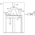
- FIG. 2 is a diagram for explaining the configuration of the three-dimensional additive manufacturing apparatus according to this embodiment.
- the three-dimensional additive manufacturing apparatus 200 includes a modeling table 201, a light source 202, a diffraction grating 203, a powder supply unit 204, a leveling member 205, and a control unit 206.
- the three-dimensional layered product 211 is modeled on the modeling table 201.
- the light source 202 emits laser light 221 for modeling the three-dimensional layered product 211 toward the modeling table 201.
- the diffraction grating 203 is arranged between the modeling table 201 and the light source 202.
- the laser light 221 emitted from the light source 202 passes through the diffraction grating 203 and reaches the modeling table 201.
- the diffraction grating 203 is an optical element for making various patterns and interference fringes from the laser light emitted from the light source 202 by utilizing diffraction and interference by a predetermined pattern, and DOE (Diffractive optical Element). Also called.
- the powder supply unit 204 stores powder 241 such as metal or resin which is a material of the three-dimensional layered product 211, and sprays the powder 241 on the modeling table 201 while moving on the modeling table 201.
- the leveling member 205 is a member for leveling the powder 241 supplied from the powder supply unit 204 while moving on the modeling table 201.
- the control unit 206 controls the scanning speed of the laser light 221.
- the control unit 206 controls the scanning speed of the laser light 221 to control the heat and energy applied to the powder 241 which is the material of the three-dimensional layered product 211.
- the control unit 206 controls the overall operation of the three-dimensional additive manufacturing apparatus 200, in addition to controlling the scanning speed of the laser light 221.
- the control unit 206 controls, for example, the operation of the powder supply unit 204 and the operation of the leveling member 205, but the target controlled by the control unit 206 is not limited to these.
- the powder supply unit 204 sprays and supplies one layer of powder 241 to the modeling table 201.
- the leveling member 205 flattens the leveled powder 241 for one layer.
- the three-dimensional additive manufacturing apparatus 200 irradiates the powder 241 with a laser beam 221 while scanning the laser beam 221.
- the powder 241 irradiated with the laser light 221 is melted.
- the powder 241 irradiated with the laser light 221 is cooled and solidified.
- the three-dimensional layered modeling apparatus 200 sets the modeling table 201 by the thickness of one layer of the three-dimensional layered product 211. Lower down. Then, the three-dimensional layered modeling apparatus 200 performs modeling for the next one layer. The three-dimensional layered modeling apparatus 200 repeats the above-described operations to model the three-dimensional layered product 211. In the illustrated three-dimensional additive manufacturing apparatus 200, a collimator lens, a condenser lens, etc. are omitted as appropriate.
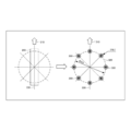
- FIG. 3A is a diagram illustrating a laser spot of the three-dimensional additive manufacturing apparatus according to this embodiment.
- FIG. 3B is a diagram illustrating a laser spot of the three-dimensional additive manufacturing apparatus according to this embodiment.
- FIG. 3C is a diagram illustrating a laser spot of the three-dimensional additive manufacturing apparatus according to this embodiment.
- These figures are views of the modeling table 201 seen from the light source 202 side, and show simulations when a single mode Gaussian laser is branched into eight equal parts by a diffraction grating 203 to form eight laser spots.
- the original laser spot diameter (laser spot diameter before branching) is ⁇ 0.1 mm, and the diameter of the laser spot 300 after eight branches is similarly ⁇ 0.1 mm.
- the laser spots 300 are arranged at equal intervals on a circle 320 having a diameter of 0.8 mm (on the circumference).
- the lines passing through the pair of two laser spots 300 on the opposite sides of the center of the circle 320 are axes 330, 340, 350 of the laser spot arrangement.
- the group of laser spots 300 moves in the scanning direction 310 of the laser beam 221 while maintaining the relative positions of the laser spots 300.
- the angle between the axes 330, 340, 350 of the laser spot arrangement and the scanning direction 310 is the yaw angle.
- the yaw angle of 45 degrees coincides with the yaw angle of 0 degrees due to the symmetry.
- the diffraction grating 203 is arranged without making an angle with respect to the scanning direction 310 of the laser light 221.
- the laser light 221 emitted from the light source 202 is branched into eight laser spots 300 by the diffraction grating 203 and arranged at equal intervals on the circumference (on the circle 320). That is, the positions of the eight laser spots 300 are displaced by a predetermined angle.
- the diameter of the circumference is ⁇ 0.8 mm and the diameter of the laser spot 300 is ⁇ 0.1 mm, but the diameter of the circle 320 and the diameter of the laser spot 300 are not limited to these, and three-dimensional lamination is possible. It is appropriately set according to the modeling conditions of the modeled object 211.
- the number of branches of the laser beam 221 branched by the diffraction grating 203 is not limited to eight branches, and may be, for example, four branches or 16 branches.
- the diffraction grating 203 is arranged at an angle to the scanning direction 310 of the laser light 221.
- the diffraction grating 203 is arranged at an angle of 11.25° (yaw angle) with respect to the scanning direction 310.
- the eight laser spots 300 are arranged on the circumference displaced (shifted) by 11.25° as compared with the arrangement of the laser spots 300 shown in FIG. 3A.
- the diffraction grating 203 is arranged at an angle of 22.5° (yaw angle) with respect to the scanning direction 310 of the laser light 221.
- the eight laser spots 300 are arranged by being displaced (shifted) by 22.5° on the circumference of the laser spot 300 as compared with the arrangement of the laser spots 300 shown in FIG. 3A.
- the angle (yaw angle) that the diffraction grating 203 is attached to the scanning direction 310 is not limited to 11.25° and 22.5°, and is appropriately selected according to the modeling conditions of the three-dimensional layered product 211. it can.
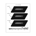
- FIG. 4A is a diagram for explaining melting simulation in the scanning direction of laser light by the three-dimensional additive manufacturing apparatus according to this embodiment.
- FIG. 4B is a diagram for explaining a melting simulation in the depth direction by the three-dimensional additive manufacturing apparatus according to this embodiment.
- the molten pool formed in the layer of the powder 241 when the yaw angle was 0°, 11.25°, and 22.5° was examined by the transient heat transfer analysis considering the melting and solidification phenomenon by the source element method.
- the analysis conditions are laser output: 960 W, laser spot diameter: ⁇ 0.1 mm, laser scanning speed: 600 mm/s, powder material: Inconel 718 (Inconel 718), powder layer thickness: 50 ⁇ m, initial temperature: 50° C. ..
- the laser output is a value before the laser light 221 is branched, and after the laser light 221 is branched, 120 W is distributed to each of the eight laser spots 300.
- the laser scanning speed was adjusted to 600 mm/s at 300 W, which is the optimum condition when modeling Inconel 718 powder by the LB (Laser Beam)-PBF (Powder Bed Fusion) method.
- FIG. 4A shows the surface temperature distribution 5 mm after the laser beam 221 starts scanning.
- the portion above the melting point of Inconel 718 becomes the molten pool.
- the diffraction grating 203 is arranged at an angle with respect to the scanning direction 310 (410), that is, the yaw angle is 0° will be described.
- each laser spot 300 When the laser beam 221 is scanned, the locus drawn by each laser spot 300 is divided into a left side, a center side, and a right side, where the temperature is high, with respect to the direction along the scanning direction 310. There is a low temperature part between and between the right side and the central part. It was shown that streaks where the molten pool was interrupted existed on both sides of the axis 330 of the laser spot arrangement parallel to the scanning direction 310, and there was a portion where the powder layer remained unmelted. Therefore, uneven melting of the powder 241 occurs, and it becomes impossible to model the three-dimensional layered product 211 of high quality.
- each laser spot 300 has a high temperature portion over the entire laser spot 300, and the entire scanning region by the laser beam 221 (each laser spot 300) is evenly distributed. It can be melted.
- the melting point by the laser spot 300 at the forefront is located in the middle of the molten pool by the laser spot 300 at the rear, and no streaks in which the powder 241 is unmelted are not formed.
- the high temperature portions are lined up in the direction along the scanning direction 310 without a gap, and the uneven melting of the powder 241 does not occur, it is possible to form the three-dimensional layered product 211 of high quality.
- the laser spots 300 arranged in this way are scanned in the scanning direction 310, the locus drawn by each laser spot 300 becomes the same as the locus drawn by one laser spot with a diameter of 0.8 mm.
- the diffraction grating 203 is arranged at an angle to the scanning direction 310 (430), that is, the yaw angle is 22.5° will be described.
- the locus drawn by each laser spot 300 is divided into a left side and a right side, where the temperature is high, and a low temperature portion is in the center, with respect to the direction along the scanning direction 210.
- a line in which the powder 241 is not melted remains on the axis 350 of the laser spot arrangement. Therefore, uneven melting of the powder 241 occurs, and it becomes impossible to model the three-dimensional layered product 211 of high quality.
- control unit 206 controls the scanning speed of the laser light 221 at a speed such that the width of the molten pool formed by each laser spot 300 is in contact with or overlaps the width of the adjacent molten pool, the powder 241 is not melted. Can be prevented from being formed. Therefore, it is possible to prevent uneven melting of the powder 241.
- FIG. 4B the distribution of the region in which the maximum temperature reached at each position is equal to or higher than the melting point of Inconel 718 (about 1340° C.) is shown in a vertical cross section perpendicular to the scanning direction 310.
- the yaw angle is 0° (440)
- the yaw angle is 11.25° (450)
- the yaw angle is 22.5° (460)
- the depth direction three-dimensional additive manufacturing
- the powder layer is formed. There is a part that is not melted. That is, there is unevenness in the distribution of the high temperature molten portion of the powder 241. Therefore, even when the heat conduction by the laser beam 221 is viewed in the depth direction, it is found that there is a portion where melting is insufficient.
- a continuous melting region is formed in the width direction. That is, in the scanning direction 310 of the laser beam 221, there is no unevenness in the distribution of the high temperature molten portion, and a continuous molten region (molten pool) of about 938 ⁇ m is secured. Further, also in the depth direction, it can be seen that the portion where the heat enters to a position deeper than 50 ⁇ m in thickness of the powder layer is continuous in the width direction. This indicates that the unmelted powder 241 does not remain inside the three-dimensional additive manufacturing object 211 during additive manufacturing by the LB-PBF method.
- the width of the melting region deeper than the thickness of the powder layer was 938 ⁇ m, which was about 4.5 times the width of about 200 ⁇ m when one laser spot 300 was scanned under optimum conditions. Since 4.5 times the width can be melted and solidified by one scan, the modeling time is 1/4.5 in simple calculation.
- the laser beam 221 is branched by the diffraction grating 203 having an appropriate yaw angle, and the laser pattern 300 in which the laser spot 300 is arranged on the circumference is scanned to melt and solidify a large area more efficiently. be able to. Further, the molding time can be shortened and the molding speed can be improved. Furthermore, when the diffraction grating 203 is arranged at a yaw angle of 11.25° with respect to the scanning direction 310, a good melting region can be obtained. That is, when the yaw angle is 11.25°, the laser light 221 can be applied to a wide range. Further, the temperature gradient in the molten pool can be reduced.
- heat when it is desired to apply heat to a wide range, that is, to make a bold print with the laser beam 221, it is possible to apply heat to a wider range by branching the laser beam 221 using the diffraction grating 203. .. Furthermore, when heat is applied to a narrow range, that is, when fine writing is performed by the laser light 221, when the diffraction grating 203 is not used (when the laser light 221 is not branched), the laser light 221 is branched. Heat can be applied to a narrow area compared to.
- the three-dimensional additive manufacturing apparatus 200 may include a moving unit that moves the diffraction grating 203 in order to control the diffraction grating 203 as described above. That is, when the diffraction grating 203 is used, the moving unit moves the diffraction grating 203 to a position on the optical path of the laser beam 221, and when the diffraction grating 203 is not used, the moving unit moves the diffraction grating 203 to the laser beam 221.
- a mirror may be arranged on the optical path of the laser light 221 and the optical path of the laser light 221 may be changed so that the laser light 221 may or may not pass through the diffraction grating 203.
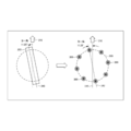
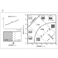
- FIG. 5A is a diagram illustrating a temperature gradient of a molten pool formed by the three-dimensional additive manufacturing apparatus according to this embodiment.
- the metal microstructure is roughly classified into columnar crystals and equiaxed crystals.
- a columnar crystal is an elongated crystal and is a crystal form formed when molten metal solidifies in one direction.
- An equiaxed crystal is a crystal form formed by solidifying in all directions with an aspect ratio close to 1.
- the conditions for forming these crystals are summarized in FIG. 5A by the temperature gradient (G K/m) and the solidification rate (R m/s).
- minute (about several ⁇ m) defects are likely to occur between columns. These minute defects reduce fatigue strength and impact strength. Therefore, if necessary, a post-heat treatment such as HIP (Hot Isostatic Processing) is performed to close it.
- aerospace materials are required to have no microdefects.
- FIG. 5B is a diagram showing GR lines of Inconel according to the present embodiment (Nastac, L., Valencia, JJ, Tims, ML, Dax , FR, Advances in the Solidification of In718 and Rs5 Alloys, in: Superalloys 718, 635, 706, and Various Derivatives, TMS, 2001, pp. 103-112.).
- FIG. 5B is a diagram (530) in which the region (520) of the conditions of the current LB-PBF method is superimposed on the measured GR diagram.
- the fastest solidification rate (R value, horizontal axis) in the molten pool is at the rear end of the molten pool, and is almost equal to the laser scanning rate.
- the current laser scanning speed is in the range of several hundred mm/s to 2000 mm/s. In order to increase the speed, it is necessary to improve the operating speed of the galvano mirror that scans the laser light, but it is predicted that the operation speed will be improved by an order of magnitude in the future.
- the temperature gradient in the molten pool can be reduced, and the metal microstructure of the metal powder changes from columnar crystals to equiaxed crystals.
- the metal microstructure becomes equiaxed, hot cracking can be suppressed.
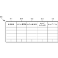
- FIG. 6 is a diagram showing an example of a scanning speed table of the three-dimensional additive manufacturing apparatus according to this embodiment.
- the scanning speed table 601 stores the inter-spot distance 612, the spot displacement amount 613, the laser spot diameter 614, and the laser power 615 in association with the scanning speed 611.
- the scanning speed 611 is the speed at which the laser light 221 is scanned.
- the inter-spot distance 612 is a distance between the adjacent laser spots 300 when the laser light 221 is branched.
- the spot displacement amount 613 indicates how much the laser spot 300 is displaced with respect to the axis 330 of the laser spot arrangement.
- the laser spot diameter 614 represents the diameter of the laser spot 300.
- the laser power 615 is an output (power) of the laser light 221, and is represented by electric power (W) or the like. In this embodiment, the laser power 615 is evenly distributed to each laser spot 300.
- the three-dimensional additive manufacturing apparatus 200 can determine the scanning speed of the laser beam 221 by referring to the scanning speed table 601.
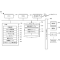
- FIG. 7 is a block diagram illustrating the hardware configuration of the three-dimensional additive manufacturing apparatus according to this embodiment.
- a CPU (Central Processing Unit) 710 is a processor for arithmetic control, and executes a program to realize the functional configuration unit of the three-dimensional additive manufacturing apparatus 200 in FIG. 2.
- the CPU 710 has a plurality of processors and may execute different programs, modules, tasks, threads, etc. in parallel.
- a ROM (Read Only Memory) 720 stores fixed data such as initial data and programs and other programs.
- the network interface 730 also communicates with other devices and the like via the network. Note that the CPU 710 is not limited to one, and may be a plurality of CPUs or may include a GPU (Graphics Processing Unit) for image processing.
- GPU Graphics Processing Unit
- the network interface 730 has a CPU independent of the CPU 710 and writes or reads transmission/reception data in an area of a RAM (Random Access Memory) 740. Further, it is desirable to provide a DMAC (Direct Memory Access Controller) for transferring data between the RAM 740 and the storage 750 (not shown). Further, the CPU 710 recognizes that the data has been received or transferred to the RAM 740 and processes the data. Further, the CPU 710 prepares the processing result in the RAM 740, and leaves the subsequent transmission or transfer to the network interface 730 or the DMAC.
- a DMAC Direct Memory Access Controller
- the RAM 740 is a random access memory used by CPU 710 as a work area for temporary storage.
- the RAM 740 has an area reserved for storing data necessary for implementing the present embodiment.
- the scanning speed 741 is a speed at which the laser light 221 is scanned.
- the spot-to-spot distance 742 is a distance between the laser spots 300.
- the spot displacement amount 743 indicates how much the laser spot 300 is displaced with respect to the axis 330 of the laser spot arrangement. That is, it is an angle of inclination (yaw angle) when the diffraction grating 203 is arranged at an angle with respect to the scanning direction 310.
- the laser spot diameter 744 is the diameter of each laser spot 300.
- the laser power 745 is the output (power) of the laser light 221.
- the modeling model 746 is data for modeling used for modeling the three-dimensional layered product 211 created using CAD (Computer Aided Design), CAM (Computer Aided Manufacturing), or the like.
- the 3D additive modeling apparatus 200 determines the modeling conditions of the 3D additive modeling 211 and the operating conditions of the 3D additive modeling apparatus 200 according to the modeling model 746, and models the 3D additive modeling 211.
- the send/receive data 747 is data sent/received via the network interface 730.
- the RAM 740 also has an application execution area 748 for executing various application modules.
- the storage 750 stores a database, various parameters, and the following data or programs necessary for realizing the present embodiment.
- the storage 750 stores the scanning speed table 601.
- the scanning speed table 601 is a table for managing the relationship between the scanning speed 611 and the laser power 615 shown in FIG.
- the storage 750 further stores a control module 751.
- the control module 751 is a module that controls the scanning speed of the laser light 221 and controls the laser light 221 at a speed such that the width of the molten pool formed by each laser spot 300 is in contact with or overlaps the width of the adjacent molten pool. This module controls the scanning speed.
- the module 751 is read by the CPU 710 into the application execution area 748 of the RAM 740 and executed.
- the control program 752 is a program for controlling the entire 3D additive manufacturing apparatus 200.
- the input/output interface 760 interfaces the input/output data with the input/output device.
- a display unit 761 and an operation unit 762 are connected to the input/output interface 760.
- a storage medium 764 may be further connected to the input/output interface 760.
- a speaker 763 that is a voice output unit, a microphone (not shown) that is a voice input unit, or a GPS position determination unit may be connected.
- the RAM 740 and the storage 750 shown in FIG. 7 do not show programs and data regarding general-purpose functions of the three-dimensional additive manufacturing apparatus 200 and other feasible functions.
- FIG. 8 is a flowchart illustrating a processing procedure of the three-dimensional additive manufacturing apparatus according to this embodiment. This flowchart is executed by the CPU 710 of FIG. 7 using the RAM 740, and realizes the functional configuration unit of the three-dimensional additive manufacturing apparatus 200 of FIG.
- step S801 the three-dimensional additive manufacturing apparatus 200 acquires a modeling model of the three-dimensional additive molded article 211.
- the modeling model is data created using CAD, CAM, or the like.
- the three-dimensional layered modeling apparatus 200 models the three-dimensional layered product 211 according to the modeling model.
- step S803 the three-dimensional additive manufacturing apparatus 200 determines the scanning speed of the laser light 221 in each layer of the three-dimensional additive manufactured object 211 based on the acquired modeling model.
- step S805 the three-dimensional additive manufacturing apparatus 200 performs the modeling of the three-dimensional additive molded article 211.
- step S807 the three-dimensional layered modeling apparatus 200 determines whether the modeling of the three-dimensional layered product 211 is completed. When it is determined that the modeling has not been completed (NO in step S807), the three-dimensional layered modeling apparatus 200 returns to step S805. When it is determined that the modeling is completed (YES in step S807), the three-dimensional layered modeling apparatus 200 ends the process.
- a wider area can be heated uniformly, so that the molding speed of the three-dimensional additive manufacturing object can be improved. Further, since the temperature gradient in the molten pool can be reduced, it is possible to suppress spatter generation and high temperature cracking.
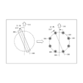
- FIG. 9 is a diagram illustrating a laser spot by the three-dimensional additive manufacturing apparatus according to this embodiment.
- the three-dimensional additive manufacturing apparatus according to the present embodiment is different from the second embodiment in the shape of the laser spot. Since other configurations and operations are similar to those of the second embodiment, the same configurations and operations are designated by the same reference numerals, and detailed description thereof will be omitted.
- the three-dimensional additive manufacturing apparatus uses a diffraction grating to split the laser light 221 emitted from the light source 202 into three laser spots (910). These three laser spots are arranged in this order from the front with respect to the scanning direction 911 of the laser light 221: a laser spot 912 for preheating, a laser spot 913 for main melting, and a laser spot 914 for postheating.
- the laser spot 912 for pre-heating and the laser spot 914 for post-heating have a larger laser spot diameter than the laser spot 913 for main melting, so that the energy of the laser light is dispersed over a wide range. Has become.
- the diameter of the laser spot By increasing the diameter of the laser spot in this way, the heat given to the powder 241 is dispersed, so that the powder 241 can be preheated and postheated.
- the intensity (power) of each laser spot is larger in the laser spot 913 for main melting than in the laser spot 912 for preheating and the laser spot 914 for postheating (920).
- the position where the laser spot 913 for main melting is irradiated is the laser spot 912 for preheating and the laser spot for postheating. It is higher than that of 914 (930).
- the laser light 211 is divided into three types: preheat, main melting, and postheat.
- the laser spot 913 for main melting, the laser spot 912 for preheating, and the laser spot 914 for postheating have different laser spot diameters and laser powers.
- the diameter of the laser spot 913 for main melting is smaller than that of the other two laser spots 912 and 914.
- the laser power of the laser spot 913 of the main melting is higher than that of the other two laser spots 912 and 914.
- the cooling rate of the powder 241 can be controlled, and a high-quality three-dimensional layered object can be molded. Further, by controlling the scanning speed of the laser beam, the spot diameters of the laser spots 912, 913, and 914 and the laser power, it is possible to produce a high-quality three-dimensional layered product.
- the laser light is branched into three to perform preheating, main melting, and postheating, it is possible to suppress the influence of spatter and fumes, and further to control the cooling rate of the powder. It is possible to form a quality three-dimensional layered object.
- FIG. 10 is a diagram illustrating a laser spot by the three-dimensional additive manufacturing apparatus according to this embodiment.
- the three-dimensional additive manufacturing apparatus according to this embodiment is different in the shape of the laser spot from the second embodiment and the third embodiment. Since other configurations and operations are the same as those in the second and third embodiments, the same configurations and operations are denoted by the same reference numerals and detailed description thereof will be omitted.
- the three-dimensional additive manufacturing apparatus uses a diffraction grating to split the laser light 221 emitted from the light source 202 into two laser spots (1010).
- the laser beam 221 is split into a central laser spot 1011 and a peripheral laser spot 1012 by a diffraction grating.
- the laser light 221 is branched by the diffraction grating so that the ring-shaped peripheral laser spot 1012 surrounds the circular central laser spot 1011.
- the laser power (1020) in this embodiment is controlled so that the peripheral laser spot 1012 has a higher laser power (intensity) than the central laser spot 1011.
- the laser beam 221 is branched and the central laser spot 1011 is inserted, so that the temperature gradient of the molten pool is small. That is, by inserting the central laser spot 1011 whose laser power is weaker than the peripheral laser spot 1012 into the peripheral laser spot 1012 whose laser power is high, the temperature gradient in the entire molten pool is reduced. Further, by adjusting the diameters of the central laser spot 1011 and the peripheral laser spot 1012, it is possible to melt the powder 241 in a wider range.
- the temperature gradient in the molten pool can be reduced, high-temperature cracking can be prevented, and a high-quality three-dimensional layered object can be formed. Moreover, since the width of the molten pool can be increased, the molding speed can be improved.
- the laser light 221 is scanned to form an "X" shape in a shorter time. Can be completed. That is, if the laser beam 221 is branched into laser spots capable of forming various shapes using the diffraction grating 203, a high-quality three-dimensional layered product 211 can be formed at higher speed.
- the diffraction gratings capable of forming the laser spots shown in the second embodiment to the fourth embodiment are attached to one three-dimensional additive manufacturing apparatus, and the diffraction gratings are switched and used to obtain a more complicated shape. Even a three-dimensional layered product of 3 can be modeled. In addition, by using a plurality of types of diffraction gratings properly, a high-quality three-dimensional layered product can be formed at higher speed.
- the present invention may be applied to a system composed of a plurality of devices or may be applied to a single device. Furthermore, the present invention can be applied to a case where an information processing program that realizes the functions of the embodiments is directly or remotely supplied to a system or an apparatus. Therefore, in order to realize the functions of the present invention on a computer, a program installed in the computer, a medium storing the program, and a WWW (World Wide Web) server for downloading the program are also included in the scope of the present invention. .. In particular, at least a non-transitory computer readable medium storing a program that causes a computer to execute the processing steps included in the above-described embodiments is included in the category of the present invention.
Landscapes
- Chemical & Material Sciences (AREA)
- Engineering & Computer Science (AREA)
- Materials Engineering (AREA)
- Manufacturing & Machinery (AREA)
- Physics & Mathematics (AREA)
- Optics & Photonics (AREA)
- Mechanical Engineering (AREA)
- Powder Metallurgy (AREA)
Abstract
Priority Applications (2)
| Application Number | Priority Date | Filing Date | Title |
|---|---|---|---|
| PCT/JP2019/004121 WO2020161809A1 (fr) | 2019-02-05 | 2019-02-05 | Imprimante 3d |
| JP2020570250A JP7149627B2 (ja) | 2019-02-05 | 2019-02-05 | 3次元積層造形装置 |
Applications Claiming Priority (1)
| Application Number | Priority Date | Filing Date | Title |
|---|---|---|---|
| PCT/JP2019/004121 WO2020161809A1 (fr) | 2019-02-05 | 2019-02-05 | Imprimante 3d |
Publications (1)
| Publication Number | Publication Date |
|---|---|
| WO2020161809A1 true WO2020161809A1 (fr) | 2020-08-13 |
Family
ID=71948113
Family Applications (1)
| Application Number | Title | Priority Date | Filing Date |
|---|---|---|---|
| PCT/JP2019/004121 WO2020161809A1 (fr) | 2019-02-05 | 2019-02-05 | Imprimante 3d |
Country Status (2)
| Country | Link |
|---|---|
| JP (1) | JP7149627B2 (fr) |
| WO (1) | WO2020161809A1 (fr) |
Cited By (1)
| Publication number | Priority date | Publication date | Assignee | Title |
|---|---|---|---|---|
| JP7325698B1 (ja) * | 2023-01-04 | 2023-08-14 | 三菱電機株式会社 | 積層造形装置 |
Citations (3)
| Publication number | Priority date | Publication date | Assignee | Title |
|---|---|---|---|---|
| JPH0332481A (ja) * | 1989-06-29 | 1991-02-13 | Komatsu Ltd | レーザ肉盛溶接装置 |
| JPH11333584A (ja) * | 1998-05-26 | 1999-12-07 | Mitsubishi Heavy Ind Ltd | レーザ加工ヘッド |
| JP2015196164A (ja) * | 2014-03-31 | 2015-11-09 | 三菱重工業株式会社 | 三次元積層装置及び三次元積層方法 |
-
2019
- 2019-02-05 JP JP2020570250A patent/JP7149627B2/ja active Active
- 2019-02-05 WO PCT/JP2019/004121 patent/WO2020161809A1/fr active Application Filing
Patent Citations (3)
| Publication number | Priority date | Publication date | Assignee | Title |
|---|---|---|---|---|
| JPH0332481A (ja) * | 1989-06-29 | 1991-02-13 | Komatsu Ltd | レーザ肉盛溶接装置 |
| JPH11333584A (ja) * | 1998-05-26 | 1999-12-07 | Mitsubishi Heavy Ind Ltd | レーザ加工ヘッド |
| JP2015196164A (ja) * | 2014-03-31 | 2015-11-09 | 三菱重工業株式会社 | 三次元積層装置及び三次元積層方法 |
Cited By (2)
| Publication number | Priority date | Publication date | Assignee | Title |
|---|---|---|---|---|
| JP7325698B1 (ja) * | 2023-01-04 | 2023-08-14 | 三菱電機株式会社 | 積層造形装置 |
| WO2024147174A1 (fr) * | 2023-01-04 | 2024-07-11 | 三菱電機株式会社 | Dispositif de fabrication additive |
Also Published As
| Publication number | Publication date |
|---|---|
| JPWO2020161809A1 (ja) | 2021-11-11 |
| JP7149627B2 (ja) | 2022-10-07 |
Similar Documents
| Publication | Publication Date | Title |
|---|---|---|
| US11020955B2 (en) | Control of solidification in laser powder bed fusion additive manufacturing using a diode laser fiber array | |
| US20200223212A1 (en) | Diode laser fiber array for powder bed fabrication or repair | |
| EP3862128B1 (fr) | Procédé de controle du taux de refroidissement d'un bain de fusion d'un lit de poudre, et système de fabrication par fusion directe de métal par laser avec un scanner laser "in-line" | |
| Yadroitsev et al. | Basics of laser powder bed fusion | |
| CN104001915B (zh) | 一种高能束增材制造大尺寸金属零部件的设备及其控制方法 | |
| KR101787718B1 (ko) | 3차원 레이저 프린팅 장치 및 방법 | |
| Tsai et al. | Synchronized multi-spot scanning strategies for the laser powder bed fusion process | |
| Jiang et al. | A support interface method for easy part removal in directed energy deposition | |
| BR112017003142B1 (pt) | Método e sistema para produzir um objeto por fabricação aditiva | |
| KR101774023B1 (ko) | 방향성 응고 합금들의 수리 | |
| CN107030283B (zh) | 使用二极管激光器光纤阵列在激光粉末床熔合加性制造中的凝固控制 | |
| EP3554795B1 (fr) | Systèmes et procédés de fabrication additive | |
| JP6787870B2 (ja) | 三次元的な物体を付加的に製造するための方法 | |
| WO2020058722A1 (fr) | Fabrication additive sur lit de poudre | |
| CN104903030A (zh) | 通过熔化粉末制造部件的方法,该粉末颗粒以冷却状态到达熔池 | |
| EP3785089B1 (fr) | Procédé et dispositif de génération de données de commande pour un dispositif de fabrication additive | |
| US11846928B2 (en) | Method for irradiating a powder layer in additive production using continuously defined production parameters | |
| CN114829043A (zh) | 粉末床熔合增材制造方法 | |
| CN104923783A (zh) | 多激光头多激光束路径扫描成形高熔点高温合金零件方法 | |
| US20220097174A1 (en) | Variable beam geometry laser-based powder bed fusion | |
| WO2020161809A1 (fr) | Imprimante 3d | |
| US8816239B2 (en) | Method of manufacturing a component | |
| US20190344382A1 (en) | Method for Reducing or Completely Closing an Opening of an Inner Contour of a Workpiece by Means of a Material Melted by a Laser Deposition Welding Device | |
| Bakhtari et al. | A Review on Laser Beam Shaping Application in Laser‐Powder Bed Fusion |
Legal Events
| Date | Code | Title | Description |
|---|---|---|---|
| 121 | Ep: the epo has been informed by wipo that ep was designated in this application |
Ref document number: 19914408 Country of ref document: EP Kind code of ref document: A1 |
|
| ENP | Entry into the national phase |
Ref document number: 2020570250 Country of ref document: JP Kind code of ref document: A |
|
| NENP | Non-entry into the national phase |
Ref country code: DE |
|
| 32PN | Ep: public notification in the ep bulletin as address of the adressee cannot be established |
Free format text: NOTING OF LOSS OF RIGHTS PURSUANT TO RULE 112(1) EPC (EPO FORM 1205A DATED 16/12/2021) |
|
| 122 | Ep: pct application non-entry in european phase |
Ref document number: 19914408 Country of ref document: EP Kind code of ref document: A1 |