WO2020158872A1 - データ送信方法、通信処理方法、装置、および通信処理プログラム - Google Patents
データ送信方法、通信処理方法、装置、および通信処理プログラム Download PDFInfo
- Publication number
- WO2020158872A1 WO2020158872A1 PCT/JP2020/003474 JP2020003474W WO2020158872A1 WO 2020158872 A1 WO2020158872 A1 WO 2020158872A1 JP 2020003474 W JP2020003474 W JP 2020003474W WO 2020158872 A1 WO2020158872 A1 WO 2020158872A1
- Authority
- WO
- WIPO (PCT)
- Prior art keywords
- address
- public key
- state information
- devices
- determined
- Prior art date
- Legal status (The legal status is an assumption and is not a legal conclusion. Google has not performed a legal analysis and makes no representation as to the accuracy of the status listed.)
- Ceased
Links
Images





Classifications
-
- H—ELECTRICITY
- H04—ELECTRIC COMMUNICATION TECHNIQUE
- H04W—WIRELESS COMMUNICATION NETWORKS
- H04W12/00—Security arrangements; Authentication; Protecting privacy or anonymity
- H04W12/06—Authentication
- H04W12/069—Authentication using certificates or pre-shared keys
-
- H—ELECTRICITY
- H04—ELECTRIC COMMUNICATION TECHNIQUE
- H04L—TRANSMISSION OF DIGITAL INFORMATION, e.g. TELEGRAPHIC COMMUNICATION
- H04L63/00—Network architectures or network communication protocols for network security
- H04L63/08—Network architectures or network communication protocols for network security for authentication of entities
- H04L63/0823—Network architectures or network communication protocols for network security for authentication of entities using certificates
-
- H—ELECTRICITY
- H04—ELECTRIC COMMUNICATION TECHNIQUE
- H04W—WIRELESS COMMUNICATION NETWORKS
- H04W12/00—Security arrangements; Authentication; Protecting privacy or anonymity
- H04W12/04—Key management, e.g. using generic bootstrapping architecture [GBA]
- H04W12/041—Key generation or derivation
-
- H—ELECTRICITY
- H04—ELECTRIC COMMUNICATION TECHNIQUE
- H04W—WIRELESS COMMUNICATION NETWORKS
- H04W40/00—Communication routing or communication path finding
- H04W40/24—Connectivity information management, e.g. connectivity discovery or connectivity update
- H04W40/248—Connectivity information update
-
- H—ELECTRICITY
- H04—ELECTRIC COMMUNICATION TECHNIQUE
- H04W—WIRELESS COMMUNICATION NETWORKS
- H04W40/00—Communication routing or communication path finding
- H04W40/24—Connectivity information management, e.g. connectivity discovery or connectivity update
- H04W40/30—Connectivity information management, e.g. connectivity discovery or connectivity update for proactive routing
-
- H—ELECTRICITY
- H04—ELECTRIC COMMUNICATION TECHNIQUE
- H04W—WIRELESS COMMUNICATION NETWORKS
- H04W8/00—Network data management
- H04W8/26—Network addressing or numbering for mobility support
-
- H—ELECTRICITY
- H04—ELECTRIC COMMUNICATION TECHNIQUE
- H04L—TRANSMISSION OF DIGITAL INFORMATION, e.g. TELEGRAPHIC COMMUNICATION
- H04L2101/00—Indexing scheme associated with group H04L61/00
- H04L2101/60—Types of network addresses
- H04L2101/604—Address structures or formats
-
- H—ELECTRICITY
- H04—ELECTRIC COMMUNICATION TECHNIQUE
- H04L—TRANSMISSION OF DIGITAL INFORMATION, e.g. TELEGRAPHIC COMMUNICATION
- H04L61/00—Network arrangements, protocols or services for addressing or naming
- H04L61/50—Address allocation
- H04L61/5007—Internet protocol [IP] addresses
- H04L61/5014—Internet protocol [IP] addresses using dynamic host configuration protocol [DHCP] or bootstrap protocol [BOOTP]
-
- H—ELECTRICITY
- H04—ELECTRIC COMMUNICATION TECHNIQUE
- H04W—WIRELESS COMMUNICATION NETWORKS
- H04W84/00—Network topologies
- H04W84/18—Self-organising networks, e.g. ad-hoc networks or sensor networks
Definitions
- the present disclosure relates to data communication technology between devices having an authenticated IP address.
- ICT Information and Communication Technology
- IP Internet Protocol
- routing In order to realize data communication between devices, the data sent from the source device must be transferred to the destination device. Such a data transfer process is called “routing” or the like. In order to realize such routing, many routers are arranged on the network.
- the router has a route information table that stores route information, and the internetworking address in the received frame and the route information table According to the contents, the route is determined and the received frame is relayed (see paragraphs [0005] and [0006] of JP-A No. 05-022293).
- Patent Document 1 assuming a network in which a large number of devices exist, a large number of routers will be required, and the responsibility of each router will increase. Therefore, in a network including a large number of devices, it is preferable that each device can realize data communication independently.
- the present disclosure provides a solution for achieving such a configuration.
- a data transmission method in a network in which a plurality of devices are connected includes a step in which each of the plurality of devices determines an IP address of each device based on a hash value calculated from a public key of each device according to a hash function, and each of the plurality of devices Holds the state information that reflects the connection relationship of each device, and sends a notification message indicating the contents of the state information to another device, and the notification message received by each of the multiple devices from the other device.
- the notification message may include identification information for identifying each device, which is calculated based on the IP address determined by each device.
- the data transmission method includes a step in which each of a plurality of devices transmits a public key held by each device and a digital certificate associated with the public key to another device, and a step of receiving the public key and the digital certificate.
- the device may further include the step of determining the IP address of the device that is the transmission source of the public key and the electronic certificate based on the hash value calculated from the public key according to the hash function.
- the determined IP address may include a predetermined unique value for identification.
- the determined IP address may include a value according to the type of device that has determined the IP address.
- a communication processing method in a device connected to a network includes a step of determining an IP address of the own device based on a hash value calculated from a public key according to a hash function, holding state information reflecting a connection relationship with another device, and state information. Is sent to other devices, the state information is updated based on the notification messages received from other devices, and the logical state is defined based on the state information held by each device. Holding a routing table used to search for a device that is a destination of data transmission among a set of devices.
- the notification message may include identification information for identifying the own device, which is calculated based on the determined IP address of the own device.
- the communication processing method may further include a step of determining a routing table when the own device is determined to operate as a root node in the set based on the state information.
- the step of holding the routing table may include the step of receiving the routing table from another device.
- the state information and notification message may include identification information for identifying the device that is the root node. If the device that is the root node included in the received notification message and the device that is the root node included in the state information do not match, one of the devices is updated according to a predetermined rule. May be determined as a root node.
- the communication processing method may further include a step of obtaining a digital certificate associated with the public key from the certificate authority and a step of transmitting the public key and the digital certificate to another device.
- the method may further include the step of determining the IP address of another device based on the hash value calculated from the public key according to the hash function.
- the determined IP address may include a predetermined unique value for identification.
- the determined IP address may include a value according to the type of device that has determined the IP address.
- a communication processing method in a device connected to a network includes a step of receiving a public key possessed by another device and a digital certificate associated with the public key, a step of judging validity of the digital certificate, and a step of validating the digital certificate. If it is determined that the IP address determined based on the hash value calculated from the public key according to the hash function is determined as the authenticated IP address of the other device, and in response to the request from the other device. And providing a service according to the authenticated IP address of the other device.
- the public key may be determined so that an IP address determined based on a hash value calculated from the public key according to a hash function matches a predetermined format.
- a device includes a network interface for connecting to a network, and a control unit connected to the network interface.
- the control unit holds the state information reflecting the process of determining the IP address of the self device and the connection relationship with another device based on the hash value calculated from the public key according to the hash function, and Logically defined based on the process of sending a notification message indicating the content to another device, the process of updating the state information based on the notification message received from the other device, and the state information held by each device
- a process of holding a routing table used to search for a device that is a destination of data transmission is executed between a set of devices.
- a communication processing program for a computer having a network interface for connecting to a network is provided.
- the communication processing program causes the computer to execute the above communication processing method.
- each device can realize data communication independently in a network including many devices.
- FIG. 6 is a diagram for explaining an IP address authentication procedure in the network system according to the present embodiment.
- FIG. 6 is a diagram showing an example of type identification information embedded in an IP address used in the network system according to the present embodiment.
- 7 is a flowchart showing a processing procedure for a device to provide an authenticated IP address in the network system according to the present embodiment.
- FIG. 7 is a sequence chart showing a processing procedure related to notification of an IP address in the network system according to the present embodiment. It is a figure for demonstrating the application example of the service provision using the network system according to this Embodiment. It is a figure for demonstrating another application example of service provision using the network system according to this Embodiment. It is a figure for demonstrating an example of the routing in the network system according to this Embodiment.
- FIG. 6 is a diagram for explaining a method of realizing routing in the network system according to the present embodiment.
- FIG. 7 is another diagram for explaining a method of realizing routing in the network system according to the present embodiment.
- 7 is a sequence chart showing a processing procedure for realizing routing in the network system according to the present embodiment. It is a figure which shows an example of the data structure of the state information and the state notification message used in the network system according to this Embodiment. It is a figure which shows the example of update of the state information by the state notification message in the network system according to this Embodiment.
- 7 is a flowchart showing a processing procedure for determining a routing table in the network system according to the present embodiment. 7 is a flowchart showing a processing procedure relating to packet transmission/reception of each device in the network system according to the present embodiment.
- FIG. 1 is a schematic diagram showing an example of the overall configuration of a network system 1 according to the present embodiment.
- a plurality of devices 100-1, 100-2, 100-3, 100-4, 100-5,... (Hereafter, referred to as “devices”) in an arbitrary network 2 such as the Internet or an intranet.
- “100” may be collectively referred to as "100".
- Some devices 100 may be connected to the network 2 via wireless communication established with the access point 4.
- another part of the device 100 may be connected to the network 2 via a wireless communication established with the mobile base station 6.
- the network 2 may include any one of a local area network (LAN), a wide area network (WAN), a radio access network (RAN), and the Internet.
- LAN local area network
- WAN wide area network
- RAN radio access network
- Each of the devices 100 connected to the network can be regarded as a “node” of the network, and the device 100 may be referred to as a “node” in the following description.
- data communication is realized between the devices 100 according to the procedure described below. Note that any physical connection method between the devices 100 may be used.
- the device 100 includes any device having a function of performing data communication with other devices using the IP address of each device.
- the device 100 may be configured as a single communication device, may be configured as a part of some object, or may be configured by being incorporated in some object.
- the device 100 is, for example, any one of a personal computer, a smartphone, a tablet, and a wearable device (for example, a smartwatch or AR glasses) worn on the user's body (for example, arm or head). May be. Further, the device 100 may be a control device installed in a smart home electric appliance, a connected automobile, a factory, or a part thereof.
- the network system 1 further includes one or more certificate authorities 200.
- Each of the certificate authorities 200 is a computer including one or a plurality of servers.
- the IP address held by each device 100 is authenticated by one or a plurality of certificate authorities 200 according to a procedure described later. As a result, each device 100 will have an authenticated IP address.
- authenticated IP address means a state in which the legitimacy of the IP address held by each device 100 is guaranteed to the communication destination or a third party. More specifically, an "authenticated IP address” means an IP address that is generated by an irreversible cryptographic hash function and that is directly or indirectly authenticated by a certificate authority (for details). Will be described later). By using such an “authenticated IP address”, it can be guaranteed that the IP address used by each device 100 for data communication is not spoofed.
- any device 100 included in the network system 1 will be uniquely specified based on the IP address of each device 100. That is, each device can determine the device to be the destination or destination of data transmission based on the IP address of each device.
- the IP address is assumed to be a global IP address that can be used for data communication between devices 100 connected to the Internet, but it may be a private IP address used only within a specific network.
- IPv4 Internet Protocol Version 4
- IPv6 Internet Protocol Version 6
- IPv6 Internet Protocol Version 6
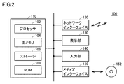
- FIG. 2 is a schematic diagram showing a hardware configuration example of device 100 according to the present embodiment.
- the device 100 includes, as a main component, a control unit 110 which is a processing circuit.
- the control unit 110 is an arithmetic entity for providing functions and executing processing according to the present embodiment.
- the control unit 110 uses the processor and the memory as shown in FIG. 2 to execute the computer readable instructions (computer readable instructions) (OS (Operating System) and communication processing program as shown in FIG. 3) stored in the memory. May be configured to perform.
- the control unit 110 may be realized by using a hard-wired circuit such as an ASIC (Application Specific Integrated Circuit) in which a circuit corresponding to a computer-readable instruction is incorporated.
- the control unit 110 may be realized by realizing a circuit corresponding to a computer-readable instruction on an FPGA (field-programmable gate array).
- the control unit 110 may be realized by appropriately combining a processor, a memory, an ASIC, an FPGA, and the like.
- control unit 110 includes a processor 102, a main memory 104, a storage 106, and a ROM (Read Only Memory) 108.
- the processor 102 is an arithmetic circuit that sequentially reads and executes computer-readable instructions.
- the processor 102 includes, for example, a CPU (Central Processing Unit), an MPU (Micro Processing Unit), and a GPU (Graphics Processing Unit).
- the control unit 110 may be implemented using a plurality of processors 102 (multiprocessor configuration), or the control unit 110 may be implemented using a processor having a plurality of cores (multicore configuration).
- the main memory 104 is a volatile storage device such as a DRAM (Dynamic Random Access Memory) or an SRAM (Static Random Access Memory).
- DRAM Dynamic Random Access Memory
- SRAM Static Random Access Memory
- the storage 106 is a non-volatile storage device such as an HDD (Hard Disk Drive), SSD (Solid State Drive), or flash memory.
- the storage 106 stores various programs executed by the processor 102 and various data described below.
- the ROM 108 fixedly stores various programs executed by the processor 102 and various data described below.
- the memory corresponds to the storage 106 and the ROM 108.
- FIG. 3 is a schematic diagram showing a configuration example of programs and data of device 100 according to the present embodiment.
- the memory (storage 106 and/or ROM 108) of device 100 stores, for example, an OS 160, a communication processing program 170, and various applications 300 as programs including computer-readable instructions.
- the OS 160 is a program that provides basic functions for realizing the processing executed by the device 100.
- Communication processing program 170 is mainly a program for implementing the provision of functions and the execution of processing according to the present embodiment.
- the communication processing program 170 may use a library or the like provided by the OS 160 to realize the function provision and the process execution according to the present embodiment.
- the various applications 300 are programs for realizing various functions provided by the device 100, and can be arbitrarily installed by the user. Typically, the various applications 300 provide various processes using the data communication function provided by the communication processing program 170.
- a private key 172, a public key 174, an electronic key 174, and an electronic key are stored as data necessary for implementing the functions and executing the processes according to the present embodiment.
- the certificate 176 is stored.
- the private key 172 and the public key 174 are so-called key pairs generated according to an arbitrary encryption/decryption algorithm.
- the secret key 172 is used for encrypted communication with another device.
- the public key 174 is used to determine the IP address of each device 100 according to the procedure described below.
- the electronic certificate 176 is issued to the public key 174 by the certificate authority 200, and is for ensuring the validity of the IP address of the device 100.
- the electronic certificate 176 includes a hash value (electronic signature) calculated from the public key 174 of each device 100 using the private key of the certificate authority 200.
- the device 100 having received the electronic certificate 176 confirms the validity of the electronic certificate 176 and the public key 174 associated with the electronic certificate 176, using the public key of the certificate authority 200.
- both the storage 106 and the ROM 108 it is not necessary to provide both the storage 106 and the ROM 108, and only one of them may be provided depending on the implementation form.
- the key pair secret key 172 and public key 174 may be stored in the ROM 108 to enhance confidentiality.
- the device 100 further includes a network interface 120 for connecting the device 100 to the network.
- the network interface 120 performs data communication with other devices via the network.
- the network interface 120 includes a wired connection terminal such as an Ethernet (registered trademark) port, a USB (Universal Serial Bus) port, a serial port such as IEEE 1394, and a legacy parallel port.
- the network interface 120 may include processing circuits and antennas for wireless communication with devices, routers, mobile base stations and the like.
- the wireless communication supported by the network interface 120 is, for example, Wi-Fi (registered trademark), Bluetooth (registered trademark), ZigBee (registered trademark), LPWA (Low Power Wide Area), GSM (registered trademark), W-CDMA, It may be any of CDMA200, LTE (Long Term Evolution), and fifth generation mobile communication system (5G).
- the device 100 may include a display unit 130, an input unit 140, and a media interface 150 as optional components.
- the display unit 130 is a component for presenting the processing result of the processor 102 and the like to the outside.
- the display unit 130 may be, for example, an LCD (Liquid Crystal Display) or an organic EL (Electro-Luminescence) display. Further, the display unit 130 may be a head mounted display mounted on the user's head or a projector that projects an image on a screen.
- the input unit 140 is a component for receiving an input operation of a user who operates the device 100.
- the input unit 140 may be, for example, a keyboard, a mouse, a touch panel arranged on the display unit 130, an operation button arranged on the housing of the device 100, or the like.
- the media interface 150 reads various programs and/or various data from a non-transitory medium 152 in which various programs (computer-readable instructions) and/or various data are stored.
- the medium 152 may be, for example, an optical medium such as a DVD (Digital Versatile Disc) or a semiconductor medium such as a USB memory.
- the media interface 150 adopts a configuration according to the type of the media 152.
- Various programs and/or various data read by the media interface 150 may be stored in the storage 106 or the like.
- various programs and/or various data may not be installed in the device 100 via the medium 152, but necessary programs and data may be installed in the device 100 from a distribution server on the network. In this case, necessary programs and data are acquired via the network interface 120.
- the display unit 130, the input unit 140, and the media interface 150 are optional components, they may be connected from the outside of the device 100 via an arbitrary interface such as USB.
- the control unit 110 realizes the provision of the function and the execution of the process according to the present embodiment, and the technical scope of the present application includes at least hardware and/or software for realizing the control unit 110.
- the hardware may include not only the configuration including the processor and the memory but also the configuration using the hard-wired circuit using the ASIC or the like or the FPGA. That is, the control unit 110 can be realized by installing a program in a general-purpose computer, or can be realized as a dedicated chip.
- the software executed by the processor may include not only software distributed via the medium 152 but also software appropriately downloaded via the distribution server.
- control unit 110 shown in FIG. 2, and can be implemented by using any technology according to the era in which it is realized.
- an authenticated IP address is used to authenticate the IP address of each device 100.
- the IP address of each device 100 may be authenticated using a public key cryptography (PKI).
- PKI public key cryptography
- FIG. 4 is a diagram for explaining an IP address authentication procedure in network system 1 according to the present embodiment.
- the symbols such as "S1" to "S4" in FIG. 4 correspond to the step numbers shown in FIG.
- the device 100 has a key pair including a private key 172 and a public key 174.
- the hash value 178 is calculated by inputting the public key 174 to the predetermined hash function 180, and all or part of the calculated hash value 178 is used as the IP address 190 of the device 100.
- the device 100 transmits the public key 174 to the certificate authority 200 along with the determination process of the IP address 190, and associates the electronic certificate 176 issued to the public key 174 by the certificate authority 200.
- the device 100 transmits the public key 174 and the electronic certificate 176 of its own device to another device.
- the other device confirms the legitimacy of the IP address 190 of the device 100 based on the public key 174 and the electronic certificate 176 published by the device 100.
- the legitimacy of the IP address 190 is confirmed, data communication is started using the legitimate IP address 190.
- the own device and the other device can directly communicate with each other, in addition to the direct communication process, the inquiry process in the certificate authority 200 may be included.
- IP address 190 itself can be authenticated, and the device itself holds such authenticated IP address 190, so that each device can be statically or dynamically operated.
- a self-sustaining network can be constructed without using the IP address that is assigned to each other.
- the private key 172 and the public key 174 which are key pairs, may be created by the device 100 itself, or may be provided from the outside and stored in the device 100 in advance. When provided externally, the device 100 may acquire only the secret key 172 and generate the public key 174 by itself.
- a bit string of a predetermined length (for example, 512 bits) generated by a random number generator is used as the secret key 172, and a known cryptographic algorithm (for example, elliptic curve cryptography) is used.
- a public key 174 composed of a bit string of a predetermined length (for example, 256 bits) may be generated from the secret key 172 according to an algorithm.
- the random number generator may be realized by using the function provided by the OS 160, or may be realized by using a hard-wired circuit such as ASIC. ..
- the hash function 180 a known irreversible cryptographic hash function (for example, BLAKE) can be used.
- the hash function 180 calculates a hash value 178 consisting of a bit string of a predetermined length (for example, 256 bits).
- a message associated with a predetermined organization may be used as an arbitrary keyword.
- a message including the name of the trademark owned by the predetermined organization may be used.
- the name of a registered trademark owned by a predetermined organization for example, “connectFree”
- connectFree may be used as a keyword to be input to the hash function 180.
- All or part of the hash value 178 calculated by the hash function 180 is used as the IP address 190.
- an arbitrary 32 digit (for example, the first 32 digits) of the 64-digit hash value 178 is an IP address corresponding to IPv6. It may be determined as 190 (128 bits).
- the first 8 digits of the 64-digit hash value 178 may be determined as the IP address 190 (32 bits) corresponding to IPv4.
- the 128-bit hash value 178 may be calculated from the hash function 180 in consideration of the IP address 190 (128 bits) corresponding to IPv6. In this case, all of the calculated hash value 178 can be determined as the IP address 190 (128 bits) corresponding to IPv6.
- the IP address 190 unique to the device 100 can be determined based on the public key 174 of the device 100. In this way, the IP address 190 determined by the device 100 can be used to connect the device 100 to a network such as the Internet. Further, the device 100 can perform data communication using the IP address 190 determined by itself even if there is no service provider (server) such as an Internet service provider (ISP) that manages a global IP address. .. Even if the device 100 does not have a server that manages a private IP address such as a DHCP (Dynamic Host Configuration Protocol) server installed in an access point or the like, the device 100 uses the IP address 190 determined by itself to access the Internet such as the Internet. Data communication can be performed by connecting to a global network. Therefore, it is possible to improve the user experience and convenience of the user when connecting to a network such as the Internet.
- server such as an Internet service provider (ISP) that manages a global IP address. ..
- ISP Internet service provider
- the IP address 190 determined by the device 100 may be able to specify that it is determined according to the processing procedure according to the present embodiment.
- the IP address 190 may include a predetermined specific value (specific character string) for identification. That is, the determined IP address may include a predetermined specific value (specific character string) for identification.
- the first two digits (first digit and second digit from the beginning) of the hexadecimal representation IP address 190 may be fixed to a predetermined unique character string (for example, “FC”). Since the hash function 180 is usually a one-way function, the public key 174 cannot be calculated backward from the IP address 190. Therefore, the private key 172 and the public key 174 are repeatedly used by using the random number generator until the determined IP address 190 satisfies the predetermined condition (in this case, the first two digits become the predetermined unique value). It may be generated. That is, the public key 174 may be determined such that the IP address 190 determined based on the hash value calculated from the public key 174 according to the hash function matches the predetermined format.
- a predetermined unique character string for example, “FC”. Since the hash function 180 is usually a one-way function, the public key 174 cannot be calculated backward from the IP address 190. Therefore, the private key 172 and the public key 174 are repeatedly used by using the random
- IP address 190 by including a predetermined specific value for identification (for example, the first two digits are “FC”) in the IP address 190, a third party can determine the IP address 190 of the device 100 by the device 100 itself. It is possible to judge whether or not it is a thing.
- a predetermined specific value for identification for example, the first two digits are “FC”
- the IP address 190 determined by the device 100 may include information that can identify the type of the device 100. In order to perform such identification, for example, the IP address 190 may include a value according to the type of the device 100. That is, the determined IP address 190 may include a value according to the type of the device 100 that determined the IP address 190.
- a value (type identification information) according to the type of the device 100 may be embedded in the third and fourth digits from the beginning of the hexadecimal representation IP address 190.
- FIG. 5 is a diagram showing an example of the type identification information embedded in the IP address used in the network system 1 according to the present embodiment.
- the type identification information shown in FIG. 5 may be stored in advance in the ROM 108 (see FIG. 2) of the control unit 110 of each device 100 or the like. As an example, a value according to the type of device as shown in FIG. 5 can be used.
- a value “00” indicating the personal computer is set at the third and fourth digits from the beginning of the IP address 190. ..
- the public key 174 cannot be calculated backward from the IP address 190. Therefore, until the determined IP address 190 satisfies a predetermined condition (in this case, the third digit and the fourth digit from the beginning have values indicating the type of the device 100), the random number generator is used to keep the secret.
- the key 172 and the public key 174 may be repeatedly generated. That is, the public key 174 may be determined such that the IP address 190 determined based on the hash value calculated from the public key 174 according to the hash function matches the predetermined format.
- a third party can specify the type of the device 100 from the IP address 190 determined by the device 100.
- the device 100 acquires an electronic certificate 176 for certifying the validity of the public key 174 from the certificate authority 200.
- the public key 174 is transmitted from the device 100 to the certificate authority 200 to be registered, and the electronic certificate 176 associated with the registered public key 174 is acquired from the certificate authority 200. ..
- the device 100 transmits a public key 174 and an electronic certificate issuance request (hereinafter, also referred to as “certificate signature request”) to the certificate authority 200 via the network. ..
- the certificate authority 200 registers the public key 174 and issues the electronic certificate 176 associated with the registered public key 174. Then, the certificate authority 200 transmits the electronic certificate 176 to the device 100 via the network.
- the digital certificate 176 includes the owner information of the digital certificate 176 (device 100 in this example), the issuer information of the digital certificate 176 (certificate authority 200 in this example), and the digital certificate of the issuer. It includes the signature and the expiration date of the electronic certificate 176.
- the certification authority 200 may be operated by a predetermined organization, or may be an intermediate certification authority associated with a root certification authority operated by a predetermined organization. Further, in registering the public key 174 and issuing the electronic certificate 176 associated with the public key 174, a predetermined fee and/or a maintenance fee may be required for a predetermined organization.
- the public key 174 is directly authenticated by the certification authority 200 through the registration of the public key 174 and the acquisition of the public key 174, so that the IP address 190 determined based on the public key 174. Is also indirectly authenticated by the certificate authority 200. By such authentication of the certificate authority 200, the device 100 can realize data communication via the network using the authenticated IP address 190.
- the electronic certificate 176 associated with the public key 174 may include information related to the attribute of the device 100 (hereinafter, also referred to as “attribute information”) in order to improve confidentiality.
- attribute information of the device 100 for example, the version information of the OS 160 and the communication processing program 170 of the device 100, the serial number of the hardware (for example, the processor or the storage) configuring the device 100, and the like can be used.
- the device 100 may transmit the attribute information of the device 100 to the certificate authority 200 when transmitting the public key 174 and the certificate signing request.
- the attribute information of the device 100 included in the electronic certificate 176 may be encrypted by a known irreversible cryptographic hash function or the like.
- the electronic certificate 176 by including the attribute information of the device 100 in the electronic certificate 176, it is possible to authenticate that the electronic certificate 176 is issued in response to the certificate signing request from the device 100 itself. That is, it is possible to more reliably prevent a device other than the device 100 from impersonating the device 100 and using the public key 174 and the electronic certificate 176 of the device 100.
- FIG. 6 is a flowchart showing a processing procedure in which device 100 provides an authenticated IP address in network system 1 according to the present embodiment.
- the processing procedure shown in FIG. 6 is executed in each device 100, and each step shown in FIG. 6 is executed by the control unit 110 of each device 100.
- the device 100 acquires a key pair (secret key 172 and public key 174) generated according to an arbitrary algorithm (step S1).
- the key pair may be generated by the device 100 itself or may be acquired by the device 100 from the outside. Alternatively, the device 100 may obtain only the private key 172 from the outside and internally generate the public key 174.
- the device 100 calculates the hash value 178 by inputting the public key 174 into the predetermined hash function 180, and obtains the IP address 190 of the device 100 from all or part of the calculated hash value 178. It is determined (step S2). That is, the device 100 determines the IP address of the device itself based on the hash value 178 calculated from the public key 174 according to the hash function 180.
- a unique character string for example, the first digit and the second digit from the beginning of the IP address 190
- type identification information for example, the third digit and the fourth digit from the beginning of the IP address 190
- Appropriate key pairs private key 172 and public key 174 may be generated to be included.
- the device 100 also transmits a public key 174 and a request to issue a digital certificate (certificate signing request) to the certificate authority 200 (step S3).
- the certificate authority 200 registers the public key 174 and issues the electronic certificate 176 associated with the registered public key 174. Then, the certificate authority 200 transmits the electronic certificate 176 to the device 100 via the network. Then, the device 100 receives and stores the electronic certificate 176 from the certificate authority 200 (step S4).
- the device 100 acquires the electronic certificate 176 associated with the public key 174 from the certificate authority.
- 7 and 8 are diagrams for explaining the process related to the notification of the IP address in network system 1 according to the present embodiment. 7 and 8 show an example of exchanging IP addresses among the three devices 100-1, 100-2, 100-3. The same processing can be performed between two devices 100, and the same processing can be performed between a larger number of devices 100.
- each of the devices 100-1, 100-2, 100-3 follows the procedure as described above, and the devices 100-1, 100-2, 100-3 have the IP address 190. -1, 190-2 and 190-3 are respectively determined, the public keys 174-1, 174-2 and 174-3 are registered in the certificate authority 200 and the electronic certificate 176- It is assumed that 1,176-2 and 176-3 have been acquired respectively.
- each device 100 transmits (broadcasts) the public key 174 of each device and the electronic certificate 176 associated with the public key 174 periodically or at each event. .. That is, each device 100 transmits the public key 174 and the electronic certificate 176 to another device. When the public key 174 is included in the electronic certificate 176, only the electronic certificate 176 may be transmitted.
- FIG. 7 shows an example in which the device 100-1 transmits (broadcasts) the public key 174-1 and the digital certificate 176-1 associated with the public key 174-1.
- the devices 100-2 and 100-3 can receive the public key 174-1 and the digital certificate 176-1 transmitted by the device 100-1. Then, the devices 100-2 and 100-3 determine whether or not the electronic certificate 176-1 is valid, and if determined to be valid, based on the associated public key 174-1. Then, the IP address 190-1 of the device 100-1 is determined and registered in the connection tables 194-2 and 194-3, respectively.
- connection table includes information of each device 100 for performing data communication, and each device 100 refers to the connection table to identify the IP address and the like of the destination device 100, A successful session.
- the device 100-2 first determines whether the electronic certificate 176-1 broadcast from the device 100-1 is valid. In the process of determining the validity, the integrity of the electronic certificate 176-1 is verified.
- the device 100-2 first confirms the existence of the owner information of the electronic certificate 176-1, the issuer information of the electronic certificate 176-1, and the digital signature of the issuer. .. Then, the device 100-2 determines whether or not the electronic certificate 176-1 is within the expiration date. Furthermore, the device 100-2 determines whether the issuer of the electronic certificate 176-1 is reliable. Particularly, when the electronic certificate 176-1 is issued by the intermediate certificate authority, the device 100-2 identifies the root certificate authority associated with the intermediate certificate authority that issued the electronic certificate 176-1 and , Determine whether or not the specified root certification authority is reliable. For example, when the specified root certification authority matches with one or a plurality of root certification authorities stored in the device 100-1, it is determined that the issuer of the electronic certificate 176-1 is reliable.
- the device 100-2 determines that the electronic certificate 176-1 broadcast from the device 100-1 is valid. Then, the device 100-2 calculates the hash value 178-1 by inputting the public key 174-1 broadcast from the device 100-1 to the predetermined hash function 180, and calculates the calculated hash value.
- the IP address 190-1 of the device 100-1 is determined using all or part of 178-1. Here, it is assumed that the devices 100-1 and 100-2 have a common hash function 180. It is also assumed that the processes for determining the IP address 190-1 from the hash value 178-1 are common between the devices 100-1 and 100-2.
- the device 100-2 can determine the IP address 190-1 of the device 100-1. Then, the device 100-2 adds the entry of the determined IP address 190-1 of the device 100-1 to the connection table 194-2.
- the public key 174-1 may be registered in association with the IP address 190-1.
- the device 100-3 also executes the same processing as the device 100-2, and the connection table 194-3 of the device 100-3 stores the entry of the determined IP address 190-1 of the device 100-1 in the connection table. Added to 194-2.
- the public key 174-1 may be registered in association with the IP address 190-1.
- the device 100-2 and the device 100-3 can obtain the IP address 190-1 of the device 100-1 by the processing as shown in FIG.
- FIG. 8 shows an example in which the device 100-2 transmits (broadcasts) the public key 174-2 and the electronic certificate 176-2 associated with the public key 174-2.
- the devices 100-1 and 100-3 can receive the public key 174-2 and the electronic certificate 176-2 transmitted by the device 100-2. Then, the devices 100-1 and 100-3 determine whether or not the electronic certificate 176-2 is valid, and if it is determined to be valid, based on the associated public key 174-2. Then, the IP address 190-2 of the device 100-2 is determined and registered in the connection tables 194-1 and 194-3, respectively.
- a series of processes executed by the devices 100-1 and 100-3 is similar to the process described with reference to FIG. 7, and thus detailed description will not be repeated.
- the device 100-1 and the device 100-3 can obtain the IP address 190-2 of the device 100-2.
- the device 100-3 may transmit (broadcast) the public key 174-3 and the electronic certificate 176-3 associated with the public key 174-3. It is assumed that the devices 100-1 and 100-2 can receive the public key 174-3 and the electronic certificate 176-3 transmitted by the device 100-3. Then, the devices 100-1 and 100-2 determine whether or not the electronic certificate 176-3 is valid, and if it is determined to be valid, based on the associated public key 174-3. Then, the IP address 190-3 of the device 100-3 is determined and registered in the connection tables 194-1 and 194-2, respectively. By such processing, the devices 100-1 and 100-2 can acquire the IP address 190-3 of the device 100-3.
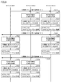
- FIG. 9 is a sequence chart showing a processing procedure related to notification of an IP address in network system 1 according to the present embodiment.
- FIG. 9 shows a processing procedure in the three devices 100-1, 100-2, 100-3 corresponding to FIGS. 7 and 8.
- the device 100-1 transmits (broadcasts) the public key 174-1 and the electronic certificate 176-1 associated with the public key 174-1 (sequence SQ10).
- the device 100-2 Upon receiving the public key 174-1 and the electronic certificate 176-1 transmitted by the device 100-1, the device 100-2 determines the validity of the electronic certificate 176-1 (sequence SQ11). If it is determined that the electronic certificate 176-1 is valid, the device 100-2 determines the IP address 190-1 of the device 100-1 based on the public key 174-1 (sequence SQ12), and determines the IP address 190-1. The IP address 190-1 of the device 100-1 is registered in the connection table 194-2 (sequence SQ13).
- the device 100-3 determines the validity of the electronic certificate 176-1 (sequence SQ14). If it is determined that the electronic certificate 176-1 is valid, the device 100-3 determines the IP address 190-1 of the device 100-1 based on the public key 174-1 (sequence SQ15), and determines the IP address 190-1. The IP address 190-1 of the device 100-1 is registered in the connection table 194-3 (sequence SQ16).
- the device 100-2 also transmits (broadcasts) the public key 174-2 and the electronic certificate 176-2 associated with the public key 174-2 (sequence SQ20).
- the device 100-1 Upon receiving the public key 174-2 and the electronic certificate 176-2 transmitted by the device 100-2, the device 100-1 determines the validity of the electronic certificate 176-2 (sequence SQ21). When it is determined that the electronic certificate 176-2 is valid, the device 100-1 determines the IP address 190-2 of the device 100-2 based on the public key 174-2 (sequence SQ22), and determines the IP address 190-2. The IP address 190-2 of the device 100-2 is registered in the connection table 194-1 (sequence SQ23).
- the device 100-3 determines the validity of the electronic certificate 176-2 (sequence SQ24). If it is determined that the electronic certificate 176-2 is valid, the device 100-3 determines the IP address 190-2 of the device 100-2 based on the public key 174-2 (sequence SQ25), and determines it. The IP address 190-2 of the device 100-2 is registered in the connection table 194-3 (sequence SQ26).
- the device 100-3 also transmits (broadcasts) the public key 174-3 and the electronic certificate 176-3 associated with the public key 174-3 (sequence SQ30).
- the device 100-1 Upon receiving the public key 174-3 and the electronic certificate 176-3 transmitted by the device 100-3, the device 100-1 determines the validity of the electronic certificate 176-3 (sequence SQ31). If it is determined that the electronic certificate 176-3 is valid, the device 100-1 determines the IP address 190-3 of the device 100-3 based on the public key 174-3 (sequence SQ32), and determines the IP address 190-3. The IP address 190-3 of the device 100-3 is registered in the connection table 194-1 (sequence SQ33).
- the device 100-2 determines the validity of the electronic certificate 176-3 (sequence SQ34). When it is determined that the electronic certificate 176-3 is valid, the device 100-2 determines the IP address 190-3 of the device 100-3 based on the public key 174-3 (sequence SQ35), and determines the IP address 190-3. The IP address 190-3 of the device 100-3 is registered in the connection table 194-2 (sequence SQ36).
- sequences SQ10 to SQ16, the processing of sequences SQ20 to SQ26, and the processing of sequences SQ30 to SQ36 may be executed in any order or in parallel.
- each device 100 determines the validity of the digital certificate 176 (sequences SQ11, SQ14, SQ21, SQ24, SQ31, SQ34). Then, when it is determined that the electronic certificate 176 is valid, each device 100 determines the IP address of another device based on the hash value calculated from the public key 174 according to the hash function (sequence SQ12, SQ15, SQ22, SQ25, SQ32, SQ35).
- the disclosure associated with electronic certificate 176 is provided on condition that electronic certificate 176 transmitted from another device 100 is determined to be valid.
- the IP address 190 of the other device 100 is determined based on the key 174. Since the IP address 190 is determined based on the public key 174 on condition that the electronic certificate 176 associated with the public key 174 is valid, the validity of the public key 174 and the validity of the IP address 190 are determined. Can be guaranteed. Therefore, reliable data communication can be realized between the devices 100.
- each device 100 since the IP address of each device 100 can be known based on public key 174 broadcast by each device 100, there is no server that manages the IP address. However, the devices 100 can be directly connected to each other. In particular, even if there is no virtual private network (VPN) server or the like, since communication in which confidentiality is ensured between the devices 100 can be realized, the cost and power consumption for maintaining the VPN server can be reduced.
- VPN virtual private network
- IP addresses can be mutually authenticated among devices 100, so that the communication destination can be specified based only on the IP address.
- Various services can be provided by using such an authenticated IP address.
- an example of the service provided using the authenticated IP address will be described.
- FIG. 10 is a diagram for explaining an application example of service provision using the network system 1 according to the present embodiment.
- the device 100 is assumed to be a web-based application server and a mobile terminal that accesses the application server.
- the application server provides a unique web page according to the authenticated IP address of the mobile terminal that is the successor.
- FIG. 10A shows an example of the network management table 210 held by the application server.
- initial screen information 214 indicating an initial screen and preference information indicating a preference are associated with an authenticated IP address 212 of a mobile terminal that has been or will be accessed in the past.
- 216 is specified.
- the contents of the network management table 210 may be manually updated by the user, or may be updated by the application server according to the user's operation.
- the application server Upon receiving the access from the mobile terminal, the application server refers to the network management table 210 using the authenticated IP address assigned to the mobile terminal as a key, and displays the corresponding initial screen information 214 and preference information 216. decide. Then, the application server determines the content of the Web page to be provided to the mobile terminal of the access source, based on the determined initial screen information 214 and preference information 216.
- FIG. 10B shows an example of a Web screen when the application server provides an online banking service, as an example.
- buttons 220 for basic account management such as “transfer procedure”, “account balance confirmation”, and “transfer procedure” are displayed on the web screen example 220A presented on the display of the mobile terminal to which the authenticated IP address 1 is assigned.
- the Web screen example 220B presented on the display of the mobile terminal to which the authenticated IP address 2 is assigned the foreign currency such as "foreign currency purchase” and "foreign currency sale” are displayed together with the chart showing the temporal change of the exchange rate. Buttons are arranged.
- Such an initial screen can be determined, for example, by referring to the initial screen information 214 of the network management table 210. Furthermore, by referring to the preference information 216 and the like of the network management table 210, it is possible to provide not only the initial screen but also a service according to preference for each mobile terminal (that is, a user who operates the mobile terminal).
- the web-based application server responds to the request from the mobile terminal and provides the service according to the authenticated IP address of the mobile terminal.
- the initial screen and various service contents provided when the application server is accessed can be customized based on the authenticated IP address of the mobile terminal.
- FIG. 11 is a diagram for explaining another application example of service provision using the network system 1 according to the present embodiment.
- the device 100 is a usage management server such as a hotel and a mobile terminal that accesses the usage management server.
- the mobile terminal can be used as an electronic key (user certificate).
- FIG. 11A shows an example of the usage management table 230 held by the server.
- the usage management table 230 stores the contents (room number 234 and available time 236) reserved through a reservation site or the like in association with the network address 232 given to the mobile terminal used for the reservation operation. ..
- the server When the user operates his/her mobile terminal to make an accommodation reservation on the reservation site, the server adds the reservation content to the usage management table 230 together with the network address given to the mobile terminal used for the accommodation reservation. ..
- a wireless communication unit 242 is arranged in front of each room of the accommodation facility 240.
- the wireless communication unit 242 wirelessly communicates with the mobile terminal.
- the wireless communication between the mobile terminal and the wireless communication unit 242 may be automatically started, or may be started after the user explicitly operates.
- the server makes a reservation based on the corresponding room number 234 and available time 236. Unlock the target room. In this way, the server responds to the request from the mobile terminal and provides the service according to the authenticated IP address of the mobile terminal.
- FIG. 11 exemplarily shows a configuration in which a mobile terminal is used as a key for each room of an accommodation facility such as a hotel, but the present invention is not limited to this and can be used as an arbitrary usage certificate.
- the mobile terminal itself can be used as an admission ticket for various facilities such as amusement facilities and various events such as concerts.
- the mobile terminal itself can be used as a ticket for railroads and aircraft.
- IP address itself of device 100 is authenticated, there is no need for an application for displaying a ticket, unlike the existing technology, and device 100 itself is used as a usage certificate. it can.
- the authenticated IP address of the mobile terminal can be obtained, so that it is possible to obtain the unique IP address of each mobile terminal without the need for an application for realizing the authentication process.
- data communication between devices such as a mobile terminal and a server means acquisition of an authenticated IP address, the time required to provide a unique service to a mobile terminal is very short, and the application Compared with the configuration in which the authentication process is performed by using, the waiting time required for providing the service can be shortened.
- each device 100 has a routing function and a data transfer function, and such a function can realize a network capable of autonomous data communication.
- FIG. 12 is a diagram for explaining an example of routing in network system 1 according to the present embodiment.
- FIG. 12 illustrates, as an example, routing in a network including seven devices 100-1 to 100-7.
- the IP address notification processing as described above enables the devices 100 having exchanged IP addresses to establish the connection 10.
- the devices 100 capable of establishing the connection 10 exchange data by a kind of peer-to-peer.
- the connection 10 between the devices 100 can employ any protocol including TCP (Transmission Control Protocol) and UDP (User Datagram Protocol).
- the transmission packet is transmitted from the device 100-1 to the device 100-5 by the routing in the device 100-1. (Route RT1), followed by routing in the device 100-5, a transmission packet is transmitted from the device 100-5 to the device 100-6 (route RT2), and finally in the device 100-6, routing is performed in the device 100-100.
- a transmission packet is transmitted from -6 to the device 100-7 (route RT3).
- Each of the devices 100 included in the network system 1 according to the present embodiment has the following functions in order to realize the routing shown in FIG.
- FIG. 13 is a diagram for explaining a method of realizing routing in network system 1 according to the present embodiment.
- a plurality of devices 100 included in network system 1 are logically defined as one or a plurality of node groups 30 (node groups 30-1, 30-2, 30-3,...) and each node group 30 shares the routing table 32 (routing tables 32-1, 32-2, 32-3,... ).
- the node group 30 means a set of devices 100 defined logically, and is determined based on the contents of the state information 40 held by each device 100, as described later.
- the routing table 32 is a table used for searching for the device 100 that is the destination of data transmission (destination of transmission packet), and can be typically realized by using a distributed hash table (Distributed Hash Table: DHT).
- the routing table 32 includes identification information for identifying the device 100 (node) included in the corresponding node group 30 and its position.
- Each of the node groups 30 includes the device 100 that becomes the root node 34 (root nodes 34-1, 34-2, 34-3,... ).
- the root node 34 is logically connected to one or a plurality of devices 100 that will be the nodes 36 in a hierarchical manner.
- FIG. 14 is another diagram for explaining a method of realizing routing in network system 1 according to the present embodiment.
- each device 100 included in the network system 1 has state information 40 (state information 40-1, 40-2) that reflects the connection relationship (logical and physical connection relationship) of each device 100. , 40-3,...) are held.
- the state information 40 reflects the connection relationship between each device 100 and another device.
- Each device 100 also periodically (for example, every few minutes) transmits a state notification message 42 indicating the content of the held state information 40 to other devices 100 existing in the surroundings.
- Each device 100 updates the state information 40 of its own device as needed based on the state notification message 42 from the other device 100.
- FIG. 14 shows an example in which the device 100-1 transmits the state notification message 42, but each device 100 included in the network system 1 transmits the state notification message 42.
- each device 100 updates the state information 40 based on the state notification message 42 from the other device 100, the tree structure as shown in FIG. 13 is logically defined.
- a value indicating that the device operates as the root node 34 is initialized in the state information 40 of each device 100.
- the state information 40 is updated based on the state notification message 42 from another device received thereafter, so that the device 100 that should operate as the root node 34 and the device 100 that should operate as the normal node 36. Will be decided autonomously.
- FIG. 15 is a sequence chart showing a processing procedure for realizing routing in network system 1 according to the present embodiment.
- FIG. 15 shows an exchange focusing on the devices 100-1, 100-2, 100-5, 100-4 shown in FIG.
- each of the devices 100-1, 100-3, 100-5, 100-4 first initializes its own state information 40 (sequence SQ100). ).
- the device 100-1 transmits a state notification message 42 indicating the content of the state information 40 of its own device to the peripheral device 100 (sequence SQ102).
- Each device that has received the state notification message 42 from the device 100-1 executes an update process for the state information 40 of its own device based on the received state notification message 42 (sequence SQ104).
- the device 100-2 transmits a state notification message 42 indicating the content of the state information 40 of its own device to the peripheral device 100 (sequence SQ106).
- Each device that has received the state notification message 42 from the device 100-2 executes the update process for the state information 40 of its own device based on the received state notification message 42 (sequence SQ108).
- the device 100-5 transmits a state notification message 42 indicating the content of the state information 40 of its own device to the peripheral device 100 (sequence SQ110).
- Each device that has received the state notification message 42 from the device 100-5 executes an update process for the state information 40 of its own device based on the received state notification message 42 (sequence SQ112).
- the device 100-4 transmits a state notification message 42 indicating the content of the state information 40 of its own device to the peripheral device 100 (sequence SQ114).
- Each device that has received the state notification message 42 from the device 100-4 executes an update process for the state information 40 of its own device based on the received state notification message 42 (sequence SQ116).
- each of the plurality of devices 100 holds the state information 40 that reflects the connection relationship of each device 100 (sequence SQ100) and transmits the state notification message 42 indicating the content of the state information 40 to other devices. (Sequence SQ102, SQ106, SQ110, SQ114). Further, each of the plurality of devices 100 updates the state information 40 held by each device 100 based on the state notification message 42 received from the other device (sequences SQ104, SQ108, SQ112, SQ116). These processes may be executed periodically.
- sequences SQ102 and SQ104, the sequences SQ106 and SQ108, the sequences SQ110 and SQ112, and the sequences SQ114 and SQ116 can be executed at mutually independent timings. Therefore, any order of execution may be used, and each may be executed in parallel.
- the device 100 operating as the root node 34 When the device 100 operating as the root node 34 is determined as a result of the transmission of the state notification message 42 by each device 100, the device 100 operating as the root node 34 (device 100-1 in the example shown in FIG. 15) is The routing table 32 is determined (sequence SQ120). In this way, between the node groups 30 (sets of devices 100) that are logically defined based on the state information 40 held by each device 100, the devices 100 included in the node group 30 are held. The process of determining the routing table 32 is executed. The routing table 32 is used to search for a device that is a destination of data transmission.
- the device 100 operating as the root node 34 transmits the determined routing table 32 to the other device 100 operating as a descendant node of the other self device (sequence SQ122).
- FIG. 15 shows an example in which each device 100 initializes the state information 40.
- an arbitrary device 100 is newly added to the network system 1 or an arbitrary device from the network system 1 is added. It is assumed that the device 100 will leave. In such a case, processing such as changing the device 100 operating as the route node 34 or updating the contents of the routing table 32 will be executed.
- each device 100 sequentially updates its own state information 40 based on the state notification message 42 exchanged between the adjacent devices 100, as shown in FIG.
- the node group 30 in which the devices 100 are hierarchically connected is logically constructed.
- FIG. 16 is a diagram showing an example of a data structure of state information 40 and state notification message 42 used in network system 1 according to the present embodiment.
- 16A shows an example of the data structure of the state information 40
- FIG. 16B shows an example of the data structure of the state notification message 42.
- the state information 40 includes ParentID 401, Child 402, Root ID 403, height 404, and binary representation (Binary Representation) 405 as setting items.
- the ParentID 401 stores identification information (typically, a KeyID described later) for identifying a device that is a parent node of each device 100.
- the children 402 stores identification information (typically, a KeyID described later) for identifying a device that is a child node of each device 100. Since the number of devices that are child nodes is not limited to one, one or more devices are stored in the children 402 in a list format.
- identification information typically, a KeyID described later
- RootID 403 stores identification information (typically, a KeyID described later) for identifying the device 100 operating as the root node 34 of the node group 30 to which each device belongs.
- the height 404 stores the height of each device in the node group 30 to which each device belongs.
- the height means the maximum value of the number of edges from the root node 34 to the leaf node in the node group 30 to which each device belongs. That is, the depth from the root node 34 to the leaf node in the node group 30 can be determined based on the size of height.
- the binary representation 405 stores identification information for identifying a device (node) to be searched in the node group 30 to which each device belongs.
- the state information 40 may include time stamp as a further setting item.
- the time stamp may be, for example, information indicating the update time of each device 100 or information indicating the time of the state notification message 42.
- Each device 100 has identification information called a KeyID for identifying its own device.
- the KeyID identification information that can uniquely identify the device 100 in the network system 1 is used.
- the KeyID may be an IP address of each device 100, or a hash value calculated from the IP address based on a hash function.
- the state notification message 42 indicates the contents of the state information 40. More specifically, the state notification message 42 includes a ParentID 421, a RootID 422, a height 423, and a KeyID 424.
- the same value as the ParentID 401 of the state information 40 is stored in the ParentID 421.
- the same value as the RootID 403 of the state information 40 is stored in the RootID 422.
- the same value as the height 404 of the state information 40 is stored in the height 423.
- the KeyID 424 stores the KeyID that is the identification information of the device itself.
- the state information 40 and the state notification message 42 include KeyID (identification information of the own device) as identification information for identifying each device 100.
- KeyID identification information of the own device
- a value calculated based on the IP address determined by each device 100 may be adopted.
- the state information 40 and the state notification message 42 also include identification information (KeyID) for identifying the device 100 that is the root node 34 of each device 100.
- KeyID identification information
- FIG. 16 shows a state in which the state information 40 and the state notification message 42 are both initialized. That is, “null” is set in the ParentID 401, the value of the KeyID of the self device (KeyID1 in the example of FIG. 16) is set in the RootID 403, and “0” is set in the height 404.
- the state information 40 initialized as shown in (a) of FIG. 16 is appropriately updated based on the state information 40 from another device.
- an example of updating the state information 40 will be described.
- FIG. 17 is a diagram showing an example of updating the state information 40 by the state notification message 42 in the network system 1 according to the present embodiment.
- the contents of the state information 40 when the devices 100-1, 100-5, and 100-6 form a tree structure in this order are updated. Indicates.
- the state information 40 of the devices 100-1, 100-5, 100-6 is initialized and then sequentially updated based on the state notification message 42 from another device.
- “KeyID1” indicating the device 100-1 is stored in the RootID 403
- the maximum number “2” of the edges from the root node 34 to the leaf node in the node group is stored in the height 404. Is stored.
- the KeyID corresponding to the connection relationship between the nodes is stored in the ParentID 401 and the Children 402 in each of the state information 40.
- the binary number representation 405 stores, for example, identification information of the number of bits according to the distance from the leaf node.
- FIG. 17 shows three types of examples (“0”, “01”, “001”) as an example.
- the tree structure of the node group is specified based on the state information 40 of each device as shown in FIG. 17, and the device 100 operating as the root node 34 determines the routing table 32 based on the specified tree structure, It is provided to each device belonging to the same node group.
- each device 100 preferably performs version management over several generations. That is, it is preferable to retain both the contents before and after updating the state information 40.
- the device 100 operating as the route node 34 determines the routing table 32 based on the appropriate version of the state information 40 among the state information 40 held by each device 100.
- FIG. 18 is a flowchart showing a processing procedure for determining a routing table in network system 1 according to the present embodiment.
- the processing related to the determination of the routing table illustrated in FIG. 18 includes processing such as determination of the node group 30 and update of the state information 40.
- Each step illustrated in FIG. 18 is executed by the control unit 110 (see FIG. 2) of the device 100 (typically realized by cooperation of a processor and a memory).
- the device 100 when the device 100 is connected to any network, the device 100 initializes the state information 40 of its own device (step S100).
- the device 100 determines whether or not the transmission condition of the state notification message 42 is satisfied (step S102). For example, it is determined whether the elapsed time from the previous state notification message 42 has reached a predetermined time.
- step S102 When the transmission condition of the state notification message 42 is satisfied (YES in step S102), the device 100 generates the state notification message 42 based on the current state information 40, and transmits the state notification message 42 to another device (step). S104). If the transmission condition of the state notification message 42 is not satisfied (NO in step S102), the process of step S104 is skipped.
- the device 100 holds the state information 40 that reflects the connection relationship with another device, and executes the process of transmitting the state notification message 42 indicating the contents of the state information 40 to the other device (step). S100 to S104).
- the device 100 determines whether or not the state notification message 42 has been received from another device (step S106). If the state notification message 42 is received from another device (YES in step S106), the device 100 determines whether or not the state information 40 needs to be updated based on the received state notification message 42. (Step S108). When it is determined that the state information 40 needs to be updated (YES in step S108), the device 100 updates the state information 40 of its own device (step S110). When it is determined that the state information 40 need not be updated (NO in step S108), the process of step S110 is skipped.
- the device 100 executes the process of updating the state information 40 based on the state notification message 42 received from the other device 100 (steps S106 to S110).
- step S106 if the state notification message 42 has not been received from another device (NO in step S106), the processes of steps S108 and S110 are skipped.
- the node group 30 as shown in FIG. 13 can determine a device included in each tree structure by determining an arbitrary device as the root node 34.
- the device 100 operating as the root node 34 may be determined based on the value of the KeyID of each device 100. That is, in the process of updating the state information 40, the device serving as the root node included in the received state notification message 42 (the device 100 specified by the KeyID stored in the RootID 422) and the state information 40 are included. If the device as the root node (the device 100 specified by the KeyID stored in the RootID 403) does not match, the process of determining one of the devices 100 as the root node is executed according to a predetermined rule. ..
- the magnitude relationship of KeyID is used as an example of a predetermined rule.
- the device having the smallest KeyID among devices in a certain range may be determined as the root node 34 of the range.
- each device 100 refers to the RootID 422 (see (b) of FIG. 16) included in the state notification message 42 received from the other device corresponding to the parent node, and determines whether the state information 40 needs to be updated. To do.
- the contents of the state information 40 are updated when the following conditions (1) and (2) are satisfied.
- the condition (1) means that the KeyID of the root node 34 recognized by the parent node is smaller than the KeyID of the root node 34 recognized by the device, and the condition (2) is This means that the parent node belongs to a tree structure that is deeper than the tree structure recognized by the device.
- the content of the state information 40 is updated so that the corresponding device is nested in the parent node. More specifically, as shown below, ParentID 401, RootID 403, and height 404 of the state information 40 are updated to the values included in the state notification message 42 received from the parent node.
- the rule for determining the root node 34 may be any rule, and the device having the largest KeyID among devices in a certain range may be determined as the root node 34 in the range, or the KeyID may be determined. The device closest to the arbitrarily set value may be determined as the root node 34. In this case, the above condition (1) may be changed as appropriate.
- the device 100 determines whether or not a sufficient number of state notification messages 42 have been received from other devices (step S112). If a sufficient number of state notification messages 42 have been received from other devices (YES in step S112), the device 100 determines the node group based on the state information 40 held by each device 100 as follows. A process of holding the routing table 32 used to search for a device that is a destination of data transmission is performed among 30 (a set of devices 100 that is logically defined) (S116, S118, S122, S124).
- the device 100 determines, based on the state information 40, whether or not the device itself operates as the root node 34 (step S114).
- the device 100 determines the routing table 32 based on the state information 40 of the self device and the state information 40 of the other device (step S116). The determined routing table 32 is transmitted to another device (step S118).
- the device 100 executes the process of determining the routing table 32.
- the device 100 transmits the state information 40 of the self device to the device set as the root node (step S120), and It is determined whether the routing table 32 has been received from the device operating as a node (step S122). If the routing table 32 is received from the device operating as the route node (YES in step S122), the device 100 stores the received routing table 32 (step S124). In this way, the device 100 holds the routing table 32 by receiving the routing table 32 from another device 100.
- step S124 If the routing table 32 is not received from the device operating as the root node (NO in step S122), the process of step S124 is skipped. If a sufficient number of state notification messages 42 have not been received from other devices (NO in step S112), the processes in and after step S102 are repeated.
- FIG. 19 is a flowchart showing a processing procedure relating to packet transmission/reception of each device 100 in network system 1 according to the present embodiment.
- FIG. 19A shows a process when a packet to be transmitted is generated in the self device
- FIG. 19B shows a process when a packet is received from another device.
- the steps shown in (a) of FIG. 19 and (b) of FIG. 19 are executed by the control unit 110 (see FIG. 2) of the device 100 (typically realized by cooperation of a processor and a memory). Be done).
- the device 100 determines whether or not a transmission packet addressed to another device is given by the various applications 300 or the like (step S200). If a transmission packet destined for another device is not given (NO in step S200), the process of step S200 is repeated.
- the device 100 refers to the routing table 32 and transmits the transmission packet to another device according to the route to the destination device. It is transmitted (step S202). At this time, if the destination device is included in the descendant node of the device itself, the device 100 transmits the transmission packet to the child node according to the route to the descendant node. On the other hand, if the destination device is not included in the descendant node of the self device, the transmission packet is transmitted to the parent node of the self device. With the above, the transmission process of the transmission packet is completed.
- step S250 it is determined whether or not a transmission packet has been received from another device (step S250). If the transmission packet is not received from another device (NO in step S250), the process of step S250 is repeated.
- the device 100 determines whether the received transmission packet is addressed to the self device (step S252). If the received transmission packet is addressed to its own device (YES in step S252), device 100 receives the transmission device and outputs it to the corresponding application 300 (step S254). This is the end of the process when the packet is received.
- the device 100 refers to the routing table 32 and transmits the transmission packet to another device according to the route to the destination device. Is transmitted (step S256).
- the process of determining the transmission destination by referring to the routing table 32 is the same as in step S202. This is the end of the process when the packet is received.
- the routing table 32 is determined and shared for each node group (a set of devices 100 defined logically).
- the routing table 32 shared by each node group when transmitting data to an arbitrary device included in the network system 1, the transmission route can be determined in a shorter time.
- each of the devices 100 included in the network system 1 transmits a state notification message 42 indicating the content of the held state information 40 to another device 100. Then, each of the devices 100, upon receiving the state notification message 42 from the other device 100, appropriately updates the content of the state information 40 held by the own device based on the content of the received state notification message 42. .. By performing such update processing of the state notification message 42 and the state information 40 periodically or periodically, even when the device 100 joins/leaves the network system 1 or the connection topology changes. , The proper routing table 32 can be maintained.
- network system 1 it is possible to provide a solution in which each device can realize data communication independently in a network including many devices.
- 1 network system 1 network system, 2 network, 4 access points, 6 mobile base stations, 10 connections, 30 node groups, 32 routing tables, 34 route nodes, 36 nodes, 40 state information, 42 state notification messages, 100 devices, 102 processors, 104 main memory, 106 storage, 108 ROM, 110 control unit, 120 network interface, 130 display unit, 140 input unit, 150 media interface, 152 media, 160 OS, 170 communication processing program, 172 private key, 174 public key, 176 Electronic certificate, 178 hash value, 180 hash function, 190 IP address, 194 connection table, 200 certificate authority, 210 network management table, 214 initial screen information, 216 preference information, 220A, 220B screen example, 230 usage management table, 232 network address, 234 room number, 236 available time, 240 accommodation, 242 wireless communication unit, 300 application, 405 binary expression, RT1, RT2, RT3 route.
Landscapes
- Engineering & Computer Science (AREA)
- Computer Networks & Wireless Communication (AREA)
- Signal Processing (AREA)
- Computer Security & Cryptography (AREA)
- Databases & Information Systems (AREA)
- Computer Hardware Design (AREA)
- Computing Systems (AREA)
- General Engineering & Computer Science (AREA)
- Data Exchanges In Wide-Area Networks (AREA)
- Mobile Radio Communication Systems (AREA)
Priority Applications (3)
| Application Number | Priority Date | Filing Date | Title |
|---|---|---|---|
| US17/427,478 US12022286B2 (en) | 2019-01-31 | 2020-01-30 | Data transmission method, communication processing method, device, and communication processing program |
| EP20749537.5A EP3920569A4 (en) | 2019-01-31 | 2020-01-30 | DATA TRANSMISSION METHOD, COMMUNICATIONS PROCESSING METHOD, DEVICE AND COMMUNICATIONS PROCESSING PROGRAM |
| US18/674,561 US12647784B2 (en) | 2019-01-31 | 2024-05-24 | Data transmission method, communication processing method, device, and communication processing program |
Applications Claiming Priority (2)
| Application Number | Priority Date | Filing Date | Title |
|---|---|---|---|
| JP2019015232A JP7437722B2 (ja) | 2019-01-31 | 2019-01-31 | データ送信方法、通信処理方法、装置、および通信処理プログラム |
| JP2019-015232 | 2019-01-31 |
Related Child Applications (2)
| Application Number | Title | Priority Date | Filing Date |
|---|---|---|---|
| US17/427,478 A-371-Of-International US12022286B2 (en) | 2019-01-31 | 2020-01-30 | Data transmission method, communication processing method, device, and communication processing program |
| US18/674,561 Continuation US12647784B2 (en) | 2019-01-31 | 2024-05-24 | Data transmission method, communication processing method, device, and communication processing program |
Publications (1)
| Publication Number | Publication Date |
|---|---|
| WO2020158872A1 true WO2020158872A1 (ja) | 2020-08-06 |
Family
ID=71840163
Family Applications (1)
| Application Number | Title | Priority Date | Filing Date |
|---|---|---|---|
| PCT/JP2020/003474 Ceased WO2020158872A1 (ja) | 2019-01-31 | 2020-01-30 | データ送信方法、通信処理方法、装置、および通信処理プログラム |
Country Status (5)
| Country | Link |
|---|---|
| US (2) | US12022286B2 (cg-RX-API-DMAC7.html) |
| EP (1) | EP3920569A4 (cg-RX-API-DMAC7.html) |
| JP (3) | JP7437722B2 (cg-RX-API-DMAC7.html) |
| TW (2) | TWI874350B (cg-RX-API-DMAC7.html) |
| WO (1) | WO2020158872A1 (cg-RX-API-DMAC7.html) |
Families Citing this family (5)
| Publication number | Priority date | Publication date | Assignee | Title |
|---|---|---|---|---|
| JP7437722B2 (ja) * | 2019-01-31 | 2024-02-26 | コネクトフリー株式会社 | データ送信方法、通信処理方法、装置、および通信処理プログラム |
| US11576037B2 (en) * | 2019-10-18 | 2023-02-07 | Huawei Technologies Co., Ltd. | Issuing offline PKI certificates in distributed V2X network |
| JP7609612B2 (ja) | 2020-11-24 | 2025-01-07 | 矢崎総業株式会社 | 無線通信装置、および、無線通信システム |
| CN120090995A (zh) * | 2023-11-30 | 2025-06-03 | 上海曦智科技有限公司 | 半导体装置及其制造方法 |
| JP2026061434A (ja) | 2024-09-30 | 2026-04-09 | ダイキン工業株式会社 | ターボ圧縮機および冷凍機 |
Citations (6)
| Publication number | Priority date | Publication date | Assignee | Title |
|---|---|---|---|---|
| JPS63155839A (ja) * | 1986-12-19 | 1988-06-29 | Hitachi Ltd | パケツト交換網のル−テイング情報管理方式 |
| JPH0522293A (ja) | 1991-07-12 | 1993-01-29 | Hitachi Ltd | ブリツジ機能付きルータ装置 |
| US20030084293A1 (en) * | 2001-10-26 | 2003-05-01 | Jari Arkko | Addressing mechanisms in mobile IP |
| JP2003298619A (ja) * | 2002-03-29 | 2003-10-17 | Sanyo Electric Co Ltd | Ipアドレス作成装置、識別情報提供装置、ipアドレス作成方法及び識別情報提供方法 |
| JP2006508583A (ja) * | 2002-11-27 | 2006-03-09 | サムスン エレクトロニクス カンパニー リミテッド | IPv6アドレスを利用してデバイスを識別する方法 |
| JP2009529846A (ja) * | 2006-03-16 | 2009-08-20 | サムスン エレクトロニクス カンパニー リミテッド | ツリー案内分散型リンクステートルーティング方法 |
Family Cites Families (12)
| Publication number | Priority date | Publication date | Assignee | Title |
|---|---|---|---|---|
| US6618366B1 (en) | 1997-12-05 | 2003-09-09 | The Distribution Systems Research Institute | Integrated information communication system |
| US7203837B2 (en) * | 2001-04-12 | 2007-04-10 | Microsoft Corporation | Methods and systems for unilateral authentication of messages |
| US7706302B2 (en) * | 2004-09-14 | 2010-04-27 | Alcatel Lucent | Optimization of routing forwarding database in a network processor |
| JP4640307B2 (ja) * | 2006-09-29 | 2011-03-02 | ブラザー工業株式会社 | コンテンツ配信システム、コンテンツ配信方法、コンテンツ配信システムにおける端末装置及びそのプログラム |
| JP5029373B2 (ja) | 2008-01-11 | 2012-09-19 | 日本電気株式会社 | ノード、経路制御方法および経路制御プログラム |
| US8498414B2 (en) | 2010-10-29 | 2013-07-30 | Telefonaktiebolaget L M Ericsson (Publ) | Secure route optimization in mobile internet protocol using trusted domain name servers |
| WO2012154751A1 (en) | 2011-05-08 | 2012-11-15 | Infinetics Technologies, Inc. | Flexible radix switching network |
| US9806994B2 (en) * | 2014-06-24 | 2017-10-31 | Mellanox Technologies, Ltd. | Routing via multiple paths with efficient traffic distribution |
| US20160066184A1 (en) | 2014-08-29 | 2016-03-03 | Intel Corporation | Pairing Computing Devices According To A Multi-Level Security Protocol |
| US10110488B2 (en) | 2015-04-23 | 2018-10-23 | Qualcomm Incorporated | Data link interface internet protocol (IP) address generation |
| WO2018126076A1 (en) * | 2016-12-30 | 2018-07-05 | Intel Corporation | Data packaging protocols for communications between iot devices |
| JP7437722B2 (ja) * | 2019-01-31 | 2024-02-26 | コネクトフリー株式会社 | データ送信方法、通信処理方法、装置、および通信処理プログラム |
-
2019
- 2019-01-31 JP JP2019015232A patent/JP7437722B2/ja active Active
-
2020
- 2020-01-30 EP EP20749537.5A patent/EP3920569A4/en active Pending
- 2020-01-30 US US17/427,478 patent/US12022286B2/en active Active
- 2020-01-30 TW TW109102813A patent/TWI874350B/zh active
- 2020-01-30 TW TW114102286A patent/TWI914149B/zh active
- 2020-01-30 WO PCT/JP2020/003474 patent/WO2020158872A1/ja not_active Ceased
-
2023
- 2023-06-19 JP JP2023100077A patent/JP7788595B2/ja active Active
-
2024
- 2024-05-24 US US18/674,561 patent/US12647784B2/en active Active
- 2024-09-03 JP JP2024151602A patent/JP2024170510A/ja active Pending
Patent Citations (6)
| Publication number | Priority date | Publication date | Assignee | Title |
|---|---|---|---|---|
| JPS63155839A (ja) * | 1986-12-19 | 1988-06-29 | Hitachi Ltd | パケツト交換網のル−テイング情報管理方式 |
| JPH0522293A (ja) | 1991-07-12 | 1993-01-29 | Hitachi Ltd | ブリツジ機能付きルータ装置 |
| US20030084293A1 (en) * | 2001-10-26 | 2003-05-01 | Jari Arkko | Addressing mechanisms in mobile IP |
| JP2003298619A (ja) * | 2002-03-29 | 2003-10-17 | Sanyo Electric Co Ltd | Ipアドレス作成装置、識別情報提供装置、ipアドレス作成方法及び識別情報提供方法 |
| JP2006508583A (ja) * | 2002-11-27 | 2006-03-09 | サムスン エレクトロニクス カンパニー リミテッド | IPv6アドレスを利用してデバイスを識別する方法 |
| JP2009529846A (ja) * | 2006-03-16 | 2009-08-20 | サムスン エレクトロニクス カンパニー リミテッド | ツリー案内分散型リンクステートルーティング方法 |
Non-Patent Citations (1)
| Title |
|---|
| See also references of EP3920569A4 |
Also Published As
| Publication number | Publication date |
|---|---|
| TWI914149B (zh) | 2026-02-01 |
| TW202034657A (zh) | 2020-09-16 |
| JP7788595B2 (ja) | 2025-12-19 |
| JP2024170510A (ja) | 2024-12-10 |
| EP3920569A4 (en) | 2022-11-23 |
| US20220132312A1 (en) | 2022-04-28 |
| US12022286B2 (en) | 2024-06-25 |
| TWI874350B (zh) | 2025-03-01 |
| US12647784B2 (en) | 2026-06-02 |
| JP2023108058A (ja) | 2023-08-03 |
| US20240314563A1 (en) | 2024-09-19 |
| JP2020123875A (ja) | 2020-08-13 |
| JP7437722B2 (ja) | 2024-02-26 |
| EP3920569A1 (en) | 2021-12-08 |
| TW202537260A (zh) | 2025-09-16 |
Similar Documents
| Publication | Publication Date | Title |
|---|---|---|
| JP7788595B2 (ja) | 通信方法およびネットワーク化システム | |
| US12192185B2 (en) | Data transmission method, communication processing method, device, and communication processing program | |
| JP7762391B2 (ja) | 通信システム、通信装置、通信方法およびプログラム | |
| JP7789293B2 (ja) | 通信装置、通信処理方法、および通信処理プログラム | |
| US9356776B2 (en) | Key managing system and method for sensor network security |
Legal Events
| Date | Code | Title | Description |
|---|---|---|---|
| 121 | Ep: the epo has been informed by wipo that ep was designated in this application |
Ref document number: 20749537 Country of ref document: EP Kind code of ref document: A1 |
|
| NENP | Non-entry into the national phase |
Ref country code: DE |
|
| ENP | Entry into the national phase |
Ref document number: 2020749537 Country of ref document: EP Effective date: 20210831 |