WO2020158702A1 - Train security system - Google Patents
Train security system Download PDFInfo
- Publication number
- WO2020158702A1 WO2020158702A1 PCT/JP2020/002894 JP2020002894W WO2020158702A1 WO 2020158702 A1 WO2020158702 A1 WO 2020158702A1 JP 2020002894 W JP2020002894 W JP 2020002894W WO 2020158702 A1 WO2020158702 A1 WO 2020158702A1
- Authority
- WO
- WIPO (PCT)
- Prior art keywords
- train
- board
- integrity
- security device
- vehicle
- Prior art date
Links
Images


Classifications
-
- B—PERFORMING OPERATIONS; TRANSPORTING
- B61—RAILWAYS
- B61L—GUIDING RAILWAY TRAFFIC; ENSURING THE SAFETY OF RAILWAY TRAFFIC
- B61L15/00—Indicators provided on the vehicle or vehicle train for signalling purposes ; On-board control or communication systems
- B61L15/0018—Communication with or on the vehicle or vehicle train
- B61L15/0036—Conductor-based, e.g. using CAN-Bus, train-line or optical fibres
-
- B—PERFORMING OPERATIONS; TRANSPORTING
- B61—RAILWAYS
- B61L—GUIDING RAILWAY TRAFFIC; ENSURING THE SAFETY OF RAILWAY TRAFFIC
- B61L15/00—Indicators provided on the vehicle or vehicle train for signalling purposes ; On-board control or communication systems
- B61L15/0054—Train integrity supervision, e.g. end-of-train [EOT] devices
-
- B—PERFORMING OPERATIONS; TRANSPORTING
- B61—RAILWAYS
- B61L—GUIDING RAILWAY TRAFFIC; ENSURING THE SAFETY OF RAILWAY TRAFFIC
- B61L23/00—Control, warning, or like safety means along the route or between vehicles or vehicle trains
- B61L23/34—Control, warnings or like safety means indicating the distance between vehicles or vehicle trains by the transmission of signals therebetween
-
- B—PERFORMING OPERATIONS; TRANSPORTING
- B61—RAILWAYS
- B61L—GUIDING RAILWAY TRAFFIC; ENSURING THE SAFETY OF RAILWAY TRAFFIC
- B61L25/00—Recording or indicating positions or identities of vehicles or vehicle trains or setting of track apparatus
- B61L25/02—Indicating or recording positions or identities of vehicles or vehicle trains
- B61L25/028—Determination of vehicle position and orientation within a train consist, e.g. serialisation
-
- Y—GENERAL TAGGING OF NEW TECHNOLOGICAL DEVELOPMENTS; GENERAL TAGGING OF CROSS-SECTIONAL TECHNOLOGIES SPANNING OVER SEVERAL SECTIONS OF THE IPC; TECHNICAL SUBJECTS COVERED BY FORMER USPC CROSS-REFERENCE ART COLLECTIONS [XRACs] AND DIGESTS
- Y02—TECHNOLOGIES OR APPLICATIONS FOR MITIGATION OR ADAPTATION AGAINST CLIMATE CHANGE
- Y02T—CLIMATE CHANGE MITIGATION TECHNOLOGIES RELATED TO TRANSPORTATION
- Y02T90/00—Enabling technologies or technologies with a potential or indirect contribution to GHG emissions mitigation
- Y02T90/10—Technologies relating to charging of electric vehicles
- Y02T90/16—Information or communication technologies improving the operation of electric vehicles
Definitions
- the present invention relates to a train security system suitable for a mobile block system.
- the "fixed block system” is a train control system that permits only one train to be in a block in one block area. Therefore, train detection using track circuits has been performed so far.
- train detection can be realized by the position report from the train, and the cost of the railway communication system can be reduced.
- CBTC and ERTMS/ETCS are mainly composed of on-board equipment and ground equipment, and communicate with each other using wireless communication.
- the on-board device recognizes the position information of the point by detecting the ground element installed on the route.
- Speed verification is performed based on the position information, train speed information, and the travel permission received from the ground device via wireless communication. Then, when the train speed exceeds the speed limit, the train is controlled by performing the brake output.
- a “mobile block system” In a railway security system using wireless communication, a “mobile block system” has been proposed instead of the "fixed block system".
- This "moving block system” aims at high-density operation and reduction of equipment for ground equipment.
- the ground device In the fixed blockage system, the ground device detects the train position based on information from the train position detection device such as the existing track circuit and accelerator counter.
- the following train control is performed.
- the onboard device reports train position information, aware knit growth and train integrity (information indicating that the knit holds the knit growth reported to the ground device) to the ground device.
- the ground device uses the information received from the on-board device to calculate information such as travel permission for each train.
- the ground device also transmits these control information to the on-board device of the following vehicle.
- the ground device can set the travel permission for the succeeding train at the rear end of the reported formation. As a result, it is possible to realize high-density operation and thus to improve the transportation capacity, as compared with the fixed block system in which only one train can be in one block section. Further, since the ground device detects the train position based on the information from the on-board device, it is possible to eliminate existing train position detection devices such as track circuits and accelerator counters.
- trains equipped with on-board equipment are required to have a mechanism for monitoring train growth and train integrity and reporting to ground equipment. Further, the information transmitted to the ground equipment is required to have high reliability and safety.
- Patent Document 1 Japanese Patent No. 6086996 proposes to implement confirmation of train integrity by mounting a mechanism for detecting connection between vehicles on each vehicle. Has been done.
- Patent Document 1 is useful for knitting in which the knitting growth of one train changes minutely depending on the operation in confirming the train integrity. That is, such as in the case of a freight train, where connection and disconnection frequently occur between vehicles, and train integrity needs to be monitored on an individual vehicle basis.
- the formation is composed of train units. That is, there is no disconnection between vehicles in train units.
- the proposal shown in Patent Document 1 has a problem that the equipment cost is increased because it is necessary to add equipment to each vehicle in the formation.
- a train security system includes a first on-board safety device mounted on a first vehicle, which is the head of a train formation, and a second on-board vehicle mounted on a second car, which is a rear end of the train formation.
- a train integrity monitoring unit having a security device and a transmission line connecting the first on-board security device and the second on-board security device, and at least the train integrity monitoring unit included in the first on-board security device is provided on the transmission line. It is characterized by monitoring the establishment or loss of train integrity of the train formation based on the communication content or communication status.
- the train on which the existing transmission line is mounted it is not necessary for the train on which the existing transmission line is mounted to mount additional equipment by using the transmission line mounted on a train basis and the onboard devices communicating with each other. Therefore, the train integrity can be monitored with the minimum configuration of the train on which the on-board device is mounted.
- the on-board devices having the fail-safe property check the soundness of prescribed procedures and messages. This makes it possible to safely and reliably transmit the train integrity information to the ground device.
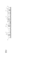
- FIG. 1 is a diagram showing an example of the overall configuration of a train security system according to an embodiment of the present invention.
- the train 1 is composed of leading cars 101 and 201 at both ends and a single or a plurality of intermediate cars 301.
- the intermediate vehicle 301 may not be provided.
- the train 1 is composed of two cars, the first cars 101 and 201.
- Train 1 has on-board devices 107 and 207 in head cars 101 and 201, respectively.
- the on-board devices 107 and 207 have train integrity monitoring units 151 and 251 inside.
- the train 1 also includes selection notification units 108 and 208 that notify the on-board devices 107 and 207 of a state in which a driver or a crew member (hereinafter, referred to as “driver etc.”) selects a driver's cab. Further, the train 1 is connected by a transmission line 2 from the beginning to the rear end of the train 1, and enables access from devices in the train. The train 1 is provided with the gateways 111 and 211 as required, and serves as an interface for connecting the on-board devices 107 and 207 to the transmission line 2.
- the transmission line 2 may be used for other purposes as long as it does not interfere with the function of the present invention, such as being connected to another device mounted on the train 1. Further, the gateways 111 and 211 may not be mounted depending on the communication mode adopted by the on-board devices 107 and 207 and the transmission line 2.
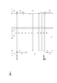
- FIG. 2 is a diagram showing a detailed configuration of the on-board device 107 and a connection relationship with other devices. Since the on-board devices 107 and 207 have the same function, they have at least the same configuration.
- the on-board device 107 includes a control unit 106, a database 152, and a communication function unit 153 inside.
- the train integrity monitoring unit 151 is provided inside the control unit 106.
- the database 152 stores parameters such as the train length and the ID of the on-board device.
- the control unit 106 reads out necessary data from the database 152 and uses it for control, and also outputs a brake command 113 to the train 1.
- the on-board device 107 communicates with the transmission line 2 in the train via the communication function unit 153.
- the gateway 111 is installed.
- the speed signal generator 103 outputs a speed signal according to the wheel rotation speed of the train.
- the selection notification unit 108 outputs a notification signal of driver's cab selection.
- the antenna 112 outputs a detection signal of a ground wire (not shown) installed on the running route of the train 1.
- the on-board device 107 receives each output signal from the speed signal generator 103, the selection notification unit 108, and the antenna 112.
- the on-board device 107 also sends and receives control information to and from a ground device (not shown) via the communication device 104. Further, the on-board device 107 outputs vehicle control information to the display device 105 to display necessary information for a driver or the like.
- the control unit 106 included in the on-board device 107 uses a fail-safe arithmetic device as the arithmetic device. This ensures the fail-safe control.
- the fail-safe arithmetic device includes a failure detection circuit and enables detection of a failure and output of a failure detection signal.
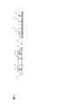
- FIG. 3 is a diagram showing an example of a specific configuration of the fail-safe calculation device.
- the fail-safe arithmetic unit shown in FIG. 3 is an arithmetic unit having a plurality of CPUs (CPU1 and CPU2 in FIG. 3) or a CPU having a multiprocessor core and a bus matching circuit.
- the bus matching circuit monitors the output signals from the CPU1 and CPU2 that are driven synchronously, and determines whether the output signals from the respective CPUs match. If they match, those signals are output from the output control circuit, and train control is executed. If they do not match, the output control circuit outputs a failure detection signal.
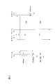
- FIG. 4 is a diagram illustrating an example of a fail-safe arithmetic device that uses software collation (data link).
- each CPU is configured to exchange calculation results, and mutually monitors whether or not the output result of itself and the calculation results of other CPUs match.
- the calculation result is applied to the control only when the calculation results of all the CPUs match.
- a shared memory is provided between CPU1 and CPU2.
- CPU1 and CPU2 confirms the calculation result of the other party written in the shared memory.
- the calculation result is transmitted to each of the output unit 1 and the output unit 2.
- the output control circuit operates and train control is executed.
- each message between the on-board devices includes a data sequence number, information indicating the contents of the message, an ID of the on-board device, and the like based on the transmission procedure, and the message is generated and read based on a specific format.
- the message will be discarded by the onboard device on the receiving side.
- each message is encrypted by the on-board device to prevent misunderstanding of communication information from other equipment connected to the transmission line and spoofing from outside. It may be converted.
- the decryption key is unique to the on-board device and can only be unlocked by the on-board device.
- the message may include the time information of the message and the mode of the on-board device, if necessary. Further, the abnormality detection of the message between the on-board devices may be displayed to the driver or the like through the display device, if necessary.
- the on-board device 107 mounted on the lead vehicle 101 detects the ground element (not shown) installed on the route with the antenna 112 and receives the position information of the ground element.
- the on-board device 107 performs speed checking based on the position information of the ground element, the speed information from the speed signal generator 103, and the control information such as travel permission obtained from the ground device from the antenna 112 and the communication device 104.
- the on-board device 107 outputs a brake command 113 to the train 1.
- the onboard device 107 transmits the position information of the train 1, the total train length, and the train integrity information to the ground device. This train integrity information ensures that the train will maintain the specified total train length without being intentionally fragmented.
- the ground device Based on the information received from the on-board device 107, the ground device sets the travel permission of the succeeding train at the rear end of the train 1 from the above position information, total train length and train integrity information. Then, the ground device transmits the control information including the travel permission to the succeeding train. The succeeding train can approach the rear end of the train 1 by obtaining the travel permission from the ground device.
- the control unit 106 of the on-board device 107 reports the loss of train integrity to the ground device.
- the ground equipment determines that the train 1 is divided on the route, and determines that the safety of this route cannot be confirmed.
- the ground device instructs the succeeding train to stop updating the travel permit or to visually check the front section by the driver or the like.
- the train integrity monitoring unit 151 provided in the control units 106 and 206 performs the function of detecting train integrity.
- the train integrity monitoring units 151 and 251 select a corresponding mode according to the state of the train 1 and the train integrity confirmation status in order to detect the train integrity.
- FIG. 5 is a diagram showing four modes defined by the on-board device.
- Standby mode 501 indicates a state in which the train is in a standby state and the train integrity has not been confirmed.
- the formation search mode 502 indicates a state in which the on-board device at the front end of the formation confirms the on-board device at the rear end before the train integrity is confirmed.
- the integrity establishment mode 503 shows a state in which the front end and the rear end in the formation are confirmed and train integrity is established by monitoring using communication.
- the integrity loss mode 504 indicates a state where the train integrity has been lost due to division within the train or the like.
- FIG. 6 is a diagram showing an example in which the train set to be operated is composed of one train.
- a driver or the like boards a leading vehicle in the traveling direction of the train and selects a driver's cab using a master key or the like.
- the vehicle on the side selected by the driver or the like is the leading vehicle 401
- the installed onboard device is the onboard device A (403).
- a vehicle on the opposite side of the leading vehicle 401 in the traveling direction is referred to as a rear end vehicle 402
- the mounted on-board device is referred to as an on-board device B (404).
- FIG. 7 is a diagram illustrating a communication procedure between the on-board device A (403) and the on-board device B (404).
- the on-board devices A and B in the train 410 are in the standby mode 501 immediately after the power is turned on or when the driver's cab is not selected immediately before the operation.
- the onboard device A receives the cab selection condition from the cab. At this time, the train integrity monitoring unit of the on-board device A transits to the formation search mode 502.
- the onboard device A transmits a message 601 to the onboard device in the composition via the transmission line 2.
- the onboard device B receives the message 601 from the transmission line 2, and the train integrity monitoring unit of the onboard device B also transits to the formation search mode 502. Then, the on-board device B transmits a confirmation message 602 with its own ID attached to the transmission line 2.
- the onboard device A By receiving the message 602 from the onboard device B, the onboard device A recognizes that the onboard device B is mounted at the rear end of the formation. After that, the on-board device A sends a message 603, which means the confirmation of the formation, to the on-board device B.
- the on-board device B Upon receiving the message 603, the on-board device B transits to the integrity establishment mode 503, and sends to the on-board device A a message 604 indicating the transition to the integrity establishment.
- the on-board device A transitions to the integrity establishment mode 503 upon receiving the message 104. After the transition to the integrity establishment mode 503, the on-board device A transmits the message 605 to the transmission line 2 at a constant cycle.
- the on-board device B sends a confirmation message 606 to the message 605 sent periodically.
- the on-board device A confirms the message 606 returned in response to the message 605 that is periodically transmitted. This establishes the train integrity of the trains in the formation and establishes train integrity.
- the train integrity monitoring units of the on-board device A and the on-board device B maintain the integrity establishment mode 503.
- the on-board device A stops the transmission of the message 605 and transmits the message 607 indicating the stop of the integrity check to the transmission line 2.
- the on-board device B receives this message 607, transitions to the standby mode 501, and transmits the integrity check completion confirmation message 608 to the on-board device A. Upon receiving the message 608, the on-board device A transitions to the standby mode 501.
- FIG. 8 is a diagram showing a case where the train 410 shown in FIG. 6 is divided.
- FIG. 9 is a diagram illustrating a communication procedure between the on-board device A and the on-board device B in the case of being divided. Before the train 410 is running and the vehicle is divided, train integrity is established as shown in FIG. 7.
- the transmission line 2 is also divided, and therefore the onboard device B cannot receive the message 605 that the onboard device A regularly transmits. Therefore, the on-board device A cannot receive the confirmation message 606 from the on-board device B for a certain period of time. As a result, the train integrity monitoring unit of the on-board device A determines that the integrity of the train has been lost, and the on-board device A transitions to the integrity loss mode 504.
- the onboard device A When transitioning to the integrity loss mode 504, the onboard device A reports the loss of train integrity to the ground device in accordance with the rules and control method of its own security device. At this time, the loss of train integrity is notified to the driver or the like through a display device (display device 105 in FIG. 2) installed in the cab.
- the train integrity monitoring unit of the onboard device B also transits to the integrity loss mode 504.
- the handling of the on-board device B mounted on the divided vehicle will be in accordance with the regulations of the safety device and train operation.
- the vehicle 402 equipped with the on-board device B interferes with the operation of the succeeding train. Therefore, it is possible to report information on the position of the train and loss of integrity to the ground device for the purpose of early implementation of the location of the vehicle and countermeasures for route operation.
- the driver or the like confirms through the display (display 105 in FIG. 2) and releases the master key. As a result, the on-board device A releases the integrity loss mode 504 and transitions to the standby mode 501.
- a driver or the like checks the display device (display device 105 in FIG. 2) and releases the master key. As a result, the on-board device B also transitions to the standby mode 501.
- FIG. 10 is a diagram showing an example in which the train set to be operated is composed of two trains. Of the two connected trains, the train a (710) on the traveling direction side and the train b (711) on the rear end side each have the train configuration shown in FIG. 1.
- a leading vehicle 701 selected by a driver or the like on the tip side of the train a is equipped with an on-board device A (705).
- the vehicle 702 on the rear end side of the train a is equipped with the on-board device B (706).
- the vehicle 703 on the leading side of the train b is equipped with the on-board device C (707).
- the vehicle 704 at the rearmost end of the train is equipped with the on-board device D (708).
- Train a and train b are connected by a connector 709 in a vehicle 702 and a vehicle 703.
- the transmission line 2 is drawn from the leading vehicle to the trailing vehicle of each train via the coupler 709 to enable mutual communication of train information.
- trains a and b have a mechanism for notifying the connection state of vehicles at the time of connection.
- the coupler 709 notifies the information indicating the vehicle coupling (hereinafter, referred to as “vehicle coupling information”) to the on-board devices of the vehicle 702 and the vehicle 703 each including the coupler 709.
- vehicle coupling information the information indicating the vehicle coupling
- each on-board device can detect whether or not the vehicle on which the device is mounted is in the connected state.
- FIG. 11 is a diagram illustrating a communication procedure in the case of the organization shown in FIG.
- the on-board device A receives the driver's cab selection condition from the driver's cab and transitions from the standby mode 501 to the formation search mode 502, as in the example shown in FIG. 6. At this time, the on-board device A transmits the message 601 to the on-board device in the formation via the transmission line 2.
- the on-board devices B, C and D receive the message 601 from the on-board device A.
- the on-board devices B and C since the on-board devices B and C have received the vehicle connection information from the connector 709, the vehicles 702 and 703 cannot be rear-end vehicles. As a result, the on-board devices B and C ignore the message 601 even if it receives the message 601, and maintain the standby mode 501.
- the on-board device D transmits the message 602 with its own ID to the transmission line 2.
- the on-board device A recognizes the on-board device D at the rear end of the formation by receiving the message 602 from the on-board device D.
- the onboard device A sends a message 603 to the onboard device D.
- the on-board device D transits to the integrity establishing mode 503 and transmits the message 604 to the on-board device A.
- the on-board device A transitions to the integrity establishment mode 503 upon receiving the message 604.
- the on-board device A detects the abnormality from the ID in the received message or the error in the procedure. In this case, the train integrity is not established and the standby mode 501 or the integrity loss mode 504 is set.
- the subsequent operations are the same as the operations when one train is formed.
- the number of vehicles equipped with the on-board device in the train is determined to be only one in the train, the leading car and the rear-end car, and three other types of connected cars. Divided into The monitoring of train integrity can be realized by the same operation as the above-mentioned two-train formation.
- FIG. 12 is a diagram showing an example in which one train set is connected to each other to form one set. In the situation shown, each of the two train sets maintains train integrity.
- the configuration of the connected trains is the same as in FIG.
- the train 711 approaches the train 710, and at the time of connection, the vehicles 701 and 703 are selected by a driver or the like.
- FIG. 13 is a diagram illustrating a communication procedure in the case of the state shown in FIG.
- Each on-board device before connection is in the integrity establishment mode 503.
- the on-board devices B and C obtain the vehicle connection information from the connector 709 before the transmission line 2 of each train is connected.
- the on-board device B sends a message 609 indicating that the connection is in progress to the on-board device A and transitions to the standby mode 501.
- the on-board device A Upon receiving the message 609, the on-board device A transits to the composition search mode 502, and periodically transmits the message 601 to the transmission line 2 for a certain period of time.
- the on-board device C transmits a message 610, which means that the vehicle is connected, to the on-board device D and transitions to the standby mode 501.
- the on-board device D receives the message 610 and transitions to the standby mode 501.
- the onboard device D After the transmission line 2 between the trains is connected, the onboard device D receives the message 601 from the onboard device A.
- the subsequent procedure for establishing train integrity is the same as the procedure for confirming train integrity for a train consisting of two trains.
- train integrity can be confirmed without intervening driver when connecting. Even in the case of connecting a train consisting of two or more trains, the monitoring of train integrity can be realized by the same operation as in the case of the above-mentioned two trains.
- FIG. 14 is a diagram showing an example in which two train sets are divided into one train set during operation. In this case, a case where one train is intentionally divided into two trains and a case where the train is unintentionally divided during traveling are included.
- FIG. 15 is a diagram illustrating a communication procedure in the case of the state shown in FIG.
- the train before division maintains train integrity.
- the coupler is released and the on-board devices B and C lose the vehicle connection information.
- the transmission line 2 between the trains is divided.
- the on-board device B transmits the message 611 to the transmission line 2 due to the loss of the vehicle connection information.
- Onboard device A receives message 611 from onboard device B and transitions to loss of integrity mode 504.
- On-board device A reports the loss of integrity to the ground device in accordance with the rules of its own security device.
- the on-board device A cannot determine whether or not the division of the formation is intended. Therefore, the on-board device A displays the loss of integrity to the driver or the like through the display ((display 105 in FIG. 2)) and requests confirmation.
- the on-board device A releases the integrity loss mode 504 from the confirmation of the driver etc. and the change of the total train length after the division. Transition to the search mode 502. However, the integrity loss mode 504 is maintained when the train is running.
- the on-board device A transmits the message 601 to the transmission line 2 after transitioning to the composition search mode 502.
- the on-board device B transmits the message 602 to the on-board device A.
- the subsequent procedure is the same as the communication procedure for one train set.
- FIG. 16 is a diagram showing an example in which a two-train formation is divided by a vehicle that is not a connecting surface of trains. The figure shows a case where the vehicle 704 in the train 711 divides the train.
- FIG. 17 is a diagram for explaining the communication procedure in the case of the state shown in FIG.
- the onboard device A does not receive the message 606 from the onboard device D for a certain period of time as in FIG. Transition to the sex loss mode 504.
- the on-board device D transits to the integrity loss mode 504 because the message 605 from the on-board device A is not received for a certain period of time.
- the on-board devices B and C are connected vehicles, and therefore the message 605 is displayed. Discard. Further, since the on-board device D is divided and cannot respond, train integrity is not established.
- the functions and modes defined above are used for handling the train integrity confirmation function and train integrity information, and for reporting the train integrity to the ground equipment. Therefore, it does not affect other functions and control modes related to the control of the on-board device.
- the cancellation condition of the integrity loss mode 504 may be changed according to the operational regulations of the security device in the state where the train is divided and the operational rules of the route.
- An example would be the receipt of a confirmation message from the ground equipment for loss of train integrity from the onboard equipment to the ground equipment.
- the on-board device 107 has at least the following three types of recognition means.
- the three types of recognition means are a master recognition means 154, a concatenation recognition means 155, and a command recognition means 156.
- the operation of the train integrity monitoring unit 151 is controlled according to the input contents from these three types of recognition means.
- the master recognition means 154 recognizes the master authority.
- the merging/recognizing means 155 monitors and recognizes the merging state associated with the own vehicle.
- the command recognition unit 156 recognizes whether or not the train is instructed to operate (in service) for the purpose of running (out of service).
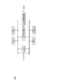
- FIG. 18 is a diagram showing the relationship between the setting by the master recognizing means 154, the merge recognizing means 155, and the command recognizing means 156 and the operating state of the on-board device.
- “1" indicates master setting and "0" indicates non-master setting.
- “1" indicates that the merge is in effect, and "0” indicates that the merge is not in effect.
- “1" indicates that an operation command has been issued, and "0” indicates that an operation command has not been issued (for example, a replacement operation command at a vehicle depot or a lateral line has been issued. State).
- the operation content by the on-board device is determined by a combination of the input content (setting content) from each recognition means. If the master recognition is "1", the merge recognition is "0”, and the command recognition is "1", the on-board device is in the "operational state", the "end of the train", and the "leading vehicle in the traveling direction”. Recognize that. Then, the on-board device operates as a master device (state) and transmits a necessary message.
- the on-board device is the master device (state) but not in the operation state (outside the operation). That is the case).
- the on-board device When the master recognition is “0” and the merge recognition is “0”, the on-board device receives a message from another on-board device that is the master device (state), or another vehicle in the same train is notified. By recognizing the master state, it operates as a slave device (state). That is, the on-board device recognizes that it is at the “end of the train” and at the “rear end vehicle in the traveling direction”. As a result, the on-board device transmits a response message in response to a message transmitted from another on-board device that is the master device (state).
- the on-board device When the master recognition is “0” and the consolidation recognition is “1”, the on-board device recognizes that its own vehicle is in operation and is arranged as an intermediate vehicle. That is, the on-board device operates as a silent device (state), and while the concatenation recognition is “1”, a message transmitted from another on-board device that is a master device (state) or a slave device (state) is displayed. Do not respond to.
- the three states described above are the basic operations of the on-board device in the operating state. Although there are other combinations of input contents (setting contents) from the respective recognizing means, they are processed as an abnormality detection state in principle. For example, when the master recognition is “1”, the concatenation recognition is “1”, and the command recognition is “1”, it is treated as an abnormality detection state except for a special case where a driving operation is performed from an intermediate vehicle of a train.
- the train when the command recognition is “0”, for example, the train is located at the depot or side track, and it can be set only when a replacement operation such as merging or splitting a formation is performed. Furthermore, it is necessary to pay attention to the fact that the safety needs to be improved when setting “0” to “1” as the command recognition setting. In other words, it is desirable that the operation procedure for switching includes the condition that a confirmation operation by a driver or the like, the incorporation of communication with a ground device, and that the train is stopped.
- the master recognition unit 154 has a function of giving an instruction of master setting or non-master setting to the control unit 106 of the on-board device 107. To achieve this, it is possible to use, for example, a master key for operating the driver's cab, a dedicated button installed on the driver's cab, a biometric authentication device, or a dedicated setting screen displayed on an indicator provided in the driver's cab. it can.
- the master recognition means 154 also operates when a driver or the like boards a train and selects a driver's cab to be operated. Upon receiving an instruction input from a driver or the like, the master recognizing unit 154 recognizes that its own on-board device is a master device (state) according to an instruction for master setting.
- the master setting instruction may be output when the cab in the traveling direction of the train is determined according to the instruction from the ground device.
- the operation mode of the on-board device that is the master device (state) will be described with reference to the example shown in FIG.
- the on-board device A is in the standby mode 501 at startup.
- the master recognition unit 154 outputs the master setting command
- the on-board device A can transit to the formation search mode 502 and transmit the message 601 as the master device (state).
- Master recognition is configured to be instructed to only one vehicle in the formation by using an interlock for the vehicle.
- another on-board device that has received the message from the on-board device that has become the master device (state) prohibits the operation of its own master recognition means 154. In this way, control may be performed so that a plurality of master devices (states) do not occur during knitting.
- a train that is in operation is required to release the consolidation or a new consolidation (in other words, it is necessary to switch the onboard device in the slave device (state) or silent device (state) to the master device (state).
- the merger recognizing unit 155 has a function of notifying the controller 106 of the on-board device 107 of the merged state. For example, it is connected to an output line of a physical detection means (not shown) for detecting the connection state of the coupler 709, an output line of an electric coupler (not shown) for forming a transmission line with another organization, and the like. It Also, it may be connected to a transmission line for acquiring the operation state of the above-mentioned physical detection means or the coupler installed at the end of the electrical coupler. Further, the control unit 106 may be equipped with a program for checking the control value in the combined state.
- the consolidation recognizing unit 155 has a hardware configuration, it is configured to capture the status signal of the device related to the consolidation, and recognizes the consolidation state according to the output of the status signal of the device. For example, when the operating state of the coupler is used for recognition of the merged state, when the coupler detects a signal output from another train, the merged recognition is “1”, and when the detection is eliminated, the merged recognition is “0”. .. The process of setting the merge recognition to "0" may be confirmed by a driver or the like.
- the command recognition unit 156 has a function of recognizing whether or not the vehicle is currently in an operating state, and this function is executed through a combination of a plurality of devices and procedures. That is, it constitutes a part of the procedure for starting train operation, and corresponds to some or all of the work such as confirmation of line section by operator etc., setting of total train length, operation command from ground equipment, etc. However, it is linked with the confirmation of those settings and work.
- the command recognition unit 156 takes in the setting of the replacement mode
- a signal that confirms this setting is sent to the command recognition unit 156. Is output.
- the command recognition unit 156 shifts the command recognition from “0” to “1” based on the confirmation of the setting of the replacement mode.
- a display for confirming whether or not the command recognition can be switched may be output to the display provided in the on-vehicle apparatus that has become the master device (state).
Abstract
In train control with a moving block system, an on-board device requires a mechanism for monitoring the number of cars and train integrity and reporting them to a ground device. Further, information that is transmitted to the ground device is required to be highly reliable and secure. Therefore, this train security system has a first on-board security device mounted on a first car located at the head of the train, a second on-board security device mounted on a second car located at the rear end of the train, and a transmission line connecting the first on-board security device and the second on-board security device. A train integrity management unit provided in at least the first on-board security device monitors establishment or loss of train integrity of the train on the basis of the content or state of communication on the transmission line.
Description
本発明は、移動閉塞方式に好適な列車保安システムに関する。
The present invention relates to a train security system suitable for a mobile block system.
「固定閉塞方式」は、1閉塞区域に1列車のみの在線を許可する列車制御方式である。そのために、これまで軌道回路を用いた列車検知が行われてきた。
しかし、近年、車上-地上間の伝送に、無線通信システムを導入する動きがある。これによって、列車からの位置報告による列車検知を実現し、鉄道通信システムのコスト低減を図ることができる。 The "fixed block system" is a train control system that permits only one train to be in a block in one block area. Therefore, train detection using track circuits has been performed so far.
However, in recent years, there is a movement to introduce a wireless communication system for transmission between the vehicle and the ground. As a result, the train detection can be realized by the position report from the train, and the cost of the railway communication system can be reduced.
米国や中国では、無線通信により列車制御を行うCBTC(Communication Based Train Control)システムの導入が進められている。
一方、欧州圏では、ERTMS(European Rail Traffic Management System)/ETCS(European Train Control System)と呼ばれるシステムが開発され、導入が進められている。このシステムは、国毎に異なる信号システムの共通化による相互運用性向上を目的とするものである。 In the United States and China, the introduction of a CBTC (Communication Based Train Control) system for controlling trains by wireless communication is being promoted.
On the other hand, in Europe, a system called ERTMS (European Rail Traffic Management System)/ETCS (European Train Control System) has been developed and is being introduced. This system aims to improve interoperability by standardizing signaling systems that differ from country to country.
鉄道保安システムとして、CBTCおよびERTMS/ETCSは、主として、車上装置と地上装置とから構成され、無線通信を用いて相互に通信を行う。車上装置は、路線上に設置された地上子を検知することで、その地点の位置情報を認識する。この位置情報、列車の速度情報および無線通信を介して地上装置から受信した走行許可などを基に速度照査を行う。そして、列車速度が制限速度を超過した場合に、ブレーキ出力を行うことで列車を制御する。
As a railway security system, CBTC and ERTMS/ETCS are mainly composed of on-board equipment and ground equipment, and communicate with each other using wireless communication. The on-board device recognizes the position information of the point by detecting the ground element installed on the route. Speed verification is performed based on the position information, train speed information, and the travel permission received from the ground device via wireless communication. Then, when the train speed exceeds the speed limit, the train is controlled by performing the brake output.
無線通信を用いた鉄道保安システムにおいて、「固定閉塞方式」に代わり、「移動閉塞方式」が提案されている。この「移動閉塞方式」は、高密度運行と地上装置の設備低減を目的とするものである。
固定閉塞方式では、地上装置は、既存の軌道回路やアクセルカウンターなどの列車位置検知装置からの情報に基づいて列車位置を検知する。 In a railway security system using wireless communication, a "mobile block system" has been proposed instead of the "fixed block system". This "moving block system" aims at high-density operation and reduction of equipment for ground equipment.
In the fixed blockage system, the ground device detects the train position based on information from the train position detection device such as the existing track circuit and accelerator counter.
一方で、移動閉塞方式では、例えば以下の列車制御を行うものである。
車上装置は、列車位置情報、認識する編成長および列車完全性(編成が地上装置に報告した編成長を保持していることを示す情報)を地上装置に報告する。地上装置は、車上装置からの受信情報を用いて、各列車の走行許可などの情報を演算する。また、地上装置は、これらの制御情報を後続車両の車上装置に対して送信する。 On the other hand, in the mobile block system, for example, the following train control is performed.
The onboard device reports train position information, aware knit growth and train integrity (information indicating that the knit holds the knit growth reported to the ground device) to the ground device. The ground device uses the information received from the on-board device to calculate information such as travel permission for each train. The ground device also transmits these control information to the on-board device of the following vehicle.
この移動閉塞方式を用いることで、地上装置は、報告された編成の後端に後続列車に対する走行許可を設定できる。これにより、1閉塞区間に1列車のみ在線可能な固定閉塞方式と比較して、高密度な運行を実現させ、よって輸送力を向上させることができる。
また、地上装置は、車上装置からの情報に基づき列車位置を検知することから、軌道回路やアクセルカウンターなどの既存の列車位置検知装置を削減することができる。 By using this movement blocking method, the ground device can set the travel permission for the succeeding train at the rear end of the reported formation. As a result, it is possible to realize high-density operation and thus to improve the transportation capacity, as compared with the fixed block system in which only one train can be in one block section.
Further, since the ground device detects the train position based on the information from the on-board device, it is possible to eliminate existing train position detection devices such as track circuits and accelerator counters.
一方で、車上装置が搭載される列車には、編成長および列車完全性を監視して地上装置に報告するための機構が要求される。さらに、地上装置に送信する情報には、高い信頼性および安全性が求められる。
On the other hand, trains equipped with on-board equipment are required to have a mechanism for monitoring train growth and train integrity and reporting to ground equipment. Further, the information transmitted to the ground equipment is required to have high reliability and safety.
また、列車完全性を確認する手段として、特許文献1(特許第6086996号公報)には、各車両に車両同士の連結を検知する機構を実装して、列車完全性の確認を実現する提案がなされている。
Further, as a means for confirming train integrity, Patent Document 1 (Japanese Patent No. 6086996) proposes to implement confirmation of train integrity by mounting a mechanism for detecting connection between vehicles on each vehicle. Has been done.
特許文献1に示される提案は、列車完全性を確認するに当たって、運用により1列車の編成長が細かく変化する編成には有用である。すなわち、貨物列車などのように、車両間に連結と切り離しが頻繁に発生し、また個々の車両単位で列車完全性の監視が必要となる場合が該当する。
一方で、旅客列車のような通常の運用では、編成は列車単位で構成される。すなわち、列車単位では車両間の切り離しが発生しない。しかしながら、特許文献1に示される提案では、編成内の各車両への設備追加が必要となり、設備費用が増加するといった課題がある。 The proposal shown inPatent Document 1 is useful for knitting in which the knitting growth of one train changes minutely depending on the operation in confirming the train integrity. That is, such as in the case of a freight train, where connection and disconnection frequently occur between vehicles, and train integrity needs to be monitored on an individual vehicle basis.
On the other hand, in a normal operation such as a passenger train, the formation is composed of train units. That is, there is no disconnection between vehicles in train units. However, the proposal shown inPatent Document 1 has a problem that the equipment cost is increased because it is necessary to add equipment to each vehicle in the formation.
一方で、旅客列車のような通常の運用では、編成は列車単位で構成される。すなわち、列車単位では車両間の切り離しが発生しない。しかしながら、特許文献1に示される提案では、編成内の各車両への設備追加が必要となり、設備費用が増加するといった課題がある。 The proposal shown in
On the other hand, in a normal operation such as a passenger train, the formation is composed of train units. That is, there is no disconnection between vehicles in train units. However, the proposal shown in
本発明に係る列車保安システムは、列車編成の先頭となる第1の車両が搭載する第1の車上保安装置と、列車編成の後端となる第2の車両が搭載する第2の車上保安装置と、第1の車上保安装置および第2の車上保安装置を接続する伝送ラインとを有し、少なくとも第1の車上保安装置が備える列車完全性監視部は、伝送ライン上の通信内容または通信状態に基づいて列車編成の列車完全性の確立または喪失を監視することを特徴とする。
A train security system according to the present invention includes a first on-board safety device mounted on a first vehicle, which is the head of a train formation, and a second on-board vehicle mounted on a second car, which is a rear end of the train formation. A train integrity monitoring unit having a security device and a transmission line connecting the first on-board security device and the second on-board security device, and at least the train integrity monitoring unit included in the first on-board security device is provided on the transmission line. It is characterized by monitoring the establishment or loss of train integrity of the train formation based on the communication content or communication status.
本発明によれば、列車単位で実装された伝送ラインを用い、車上装置が互いに通信を実施することにより、既存の伝送ラインが実装された列車が追加設備を実装することは必要ない。したがって、車上装置が搭載される列車の最小構成で、列車完全性の監視を実現することが可能となる。
According to the present invention, it is not necessary for the train on which the existing transmission line is mounted to mount additional equipment by using the transmission line mounted on a train basis and the onboard devices communicating with each other. Therefore, the train integrity can be monitored with the minimum configuration of the train on which the on-board device is mounted.
また、本発明によれば、フェールセーフ性を備えた車上装置同士が規定の手順やメッセージの健全性をチェックする。これにより、列車完全性の情報を安全で確実に地上装置へ送信することを実現できる。
Further, according to the present invention, the on-board devices having the fail-safe property check the soundness of prescribed procedures and messages. This makes it possible to safely and reliably transmit the train integrity information to the ground device.
以下、本発明を実施するための形態として、実施例について図を参照しながら詳細に説明する。
Hereinafter, as embodiments for carrying out the present invention, embodiments will be described in detail with reference to the drawings.
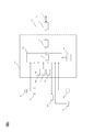
図1は、本発明の実施例に係る列車保安システムの全体構成の一例を示す図である。
列車1は、両端に先頭車両101、201、および、単一もしくは複数の中間車両301から編成される。列車1の編成によっては、中間車両301が設けられない場合もある。この場合、列車1は、先頭車両101および201の2車両から編成される。 FIG. 1 is a diagram showing an example of the overall configuration of a train security system according to an embodiment of the present invention.
Thetrain 1 is composed of leading cars 101 and 201 at both ends and a single or a plurality of intermediate cars 301. Depending on the formation of the train 1, the intermediate vehicle 301 may not be provided. In this case, the train 1 is composed of two cars, the first cars 101 and 201.
列車1は、両端に先頭車両101、201、および、単一もしくは複数の中間車両301から編成される。列車1の編成によっては、中間車両301が設けられない場合もある。この場合、列車1は、先頭車両101および201の2車両から編成される。 FIG. 1 is a diagram showing an example of the overall configuration of a train security system according to an embodiment of the present invention.
The
列車1は、先頭車両101および201に、それぞれ車上装置107および207を有する。車上装置107および207は、内部に列車完全性監視部151および251を有する。
Train 1 has on- board devices 107 and 207 in head cars 101 and 201, respectively. The on- board devices 107 and 207 have train integrity monitoring units 151 and 251 inside.
また、列車1は、運転士または乗務員(以下、「運転士等」という)が運転台を選択した状態を車上装置107および207に通知する選択通知部108および208を備える。さらに、列車1は、伝送ライン2によって列車1の先頭から後端までが接続され、列車内の機器からのアクセスを可能にしている。、必要に応じて、列車1は、ゲートウェイ111および211を設け、車上装置107および207を伝送ライン2に接続するためのインターフェイスとする。
The train 1 also includes selection notification units 108 and 208 that notify the on- board devices 107 and 207 of a state in which a driver or a crew member (hereinafter, referred to as “driver etc.”) selects a driver's cab. Further, the train 1 is connected by a transmission line 2 from the beginning to the rear end of the train 1, and enables access from devices in the train. The train 1 is provided with the gateways 111 and 211 as required, and serves as an interface for connecting the on- board devices 107 and 207 to the transmission line 2.
ここで、伝送ライン2は、列車1に搭載される他の装置に接続されるなど、本発明の機能を妨げない限りにおいて他の用途に使用されてもよい。また、ゲートウェイ111、211は、車上装置107および207と伝送ライン2とが採用する通信形態により実装されない場合もある。
Here, the transmission line 2 may be used for other purposes as long as it does not interfere with the function of the present invention, such as being connected to another device mounted on the train 1. Further, the gateways 111 and 211 may not be mounted depending on the communication mode adopted by the on- board devices 107 and 207 and the transmission line 2.
図2は、車上装置107の詳細構成および他の機器との接続関係を示す図である。なお、車上装置107と207とは、機能が共通することから、少なくとも同様の構成を有するものである。
FIG. 2 is a diagram showing a detailed configuration of the on-board device 107 and a connection relationship with other devices. Since the on- board devices 107 and 207 have the same function, they have at least the same configuration.
車上装置107は、内部に、制御部106、データベース152および通信機能部153を備える。列車完全性監視部151は、制御部106の内部に設けられる。データベース152は、列車長や車上装置のIDなどのパラメータを保存する。制御部106は、データベース152から必要なデータを読み出して制御に使用し、また、ブレーキ指令113を列車1に出力する。
The on-board device 107 includes a control unit 106, a database 152, and a communication function unit 153 inside. The train integrity monitoring unit 151 is provided inside the control unit 106. The database 152 stores parameters such as the train length and the ID of the on-board device. The control unit 106 reads out necessary data from the database 152 and uses it for control, and also outputs a brake command 113 to the train 1.
車上装置107は、列車内の伝送ライン2との通信を通信機能部153を介して行う。伝送ライン2と通信機能部153とが有する通信仕様が異なる場合には、ゲートウェイ111が実装される。
The on-board device 107 communicates with the transmission line 2 in the train via the communication function unit 153. When the communication specifications of the transmission line 2 and the communication function unit 153 are different, the gateway 111 is installed.
速度信号発生器103は、列車の車輪回転数に応じた速度信号を出力する。選択通知部108は、運転台選択の通知信号を出力する。アンテナ112は、列車1の走行路線上に設置された地上子(図示せず)の検知信号を出力する。車上装置107は、速度信号発生器103、選択通知部108およびアンテナ112からの各出力信号を受信する。
The speed signal generator 103 outputs a speed signal according to the wheel rotation speed of the train. The selection notification unit 108 outputs a notification signal of driver's cab selection. The antenna 112 outputs a detection signal of a ground wire (not shown) installed on the running route of the train 1. The on-board device 107 receives each output signal from the speed signal generator 103, the selection notification unit 108, and the antenna 112.
また、車上装置107は、通信装置104を介して地上装置(図示せず)と制御情報を送受信する。さらに、車上装置107は、表示器105に車両制御情報を出力し、運転士等に必要な情報を表示する。
The on-board device 107 also sends and receives control information to and from a ground device (not shown) via the communication device 104. Further, the on-board device 107 outputs vehicle control information to the display device 105 to display necessary information for a driver or the like.
次に、車上装置107が備える制御部106について説明する。
制御部106は、演算装置としてフェールセーフ演算装置を用いる。これにより、制御のフェールセーフ性を担保している。フェールセーフ演算装置は、故障検知回路を含み、故障を検知し故障検知信号を出力することを可能にする。 Next, thecontrol unit 106 included in the on-board device 107 will be described.
Thecontrol unit 106 uses a fail-safe arithmetic device as the arithmetic device. This ensures the fail-safe control. The fail-safe arithmetic device includes a failure detection circuit and enables detection of a failure and output of a failure detection signal.
制御部106は、演算装置としてフェールセーフ演算装置を用いる。これにより、制御のフェールセーフ性を担保している。フェールセーフ演算装置は、故障検知回路を含み、故障を検知し故障検知信号を出力することを可能にする。 Next, the
The
図3は、フェールセーフ演算装置の具体的構成の一例を示す図である。
図3に示すフェールセーフ演算装置は、複数のCPU(図3では、CPU1およびCPU2)またはマルチプロセッサコアを有するCPUおよびバス照合回路を有する演算装置である。 FIG. 3 is a diagram showing an example of a specific configuration of the fail-safe calculation device.
The fail-safe arithmetic unit shown in FIG. 3 is an arithmetic unit having a plurality of CPUs (CPU1 and CPU2 in FIG. 3) or a CPU having a multiprocessor core and a bus matching circuit.
バス照合回路は、同期駆動するCPU1およびCPU2からの出力信号を監視し、それぞれのCPUからの出力信号が一致するか否かを判定する。一致する場合は、それらの信号が出力制御回路から出力され、列車制御が実行される。一致しない場合は、出力制御回路から故障検知信号が出力される。
The bus matching circuit monitors the output signals from the CPU1 and CPU2 that are driven synchronously, and determines whether the output signals from the respective CPUs match. If they match, those signals are output from the output control circuit, and train control is executed. If they do not match, the output control circuit outputs a failure detection signal.
また、バス照合回路のようなハードウェア構成に依らず、ソフトウェア的に対処することも可能である。図4は、ソフトウェア照合(データリンク)を利用するフェールセーフ演算装置の一例を示す図である。
Also, it is possible to deal with it by software without depending on the hardware configuration such as the bus matching circuit. FIG. 4 is a diagram illustrating an example of a fail-safe arithmetic device that uses software collation (data link).
ソフトウェア照合を実装する場合、例えば、CPUそれぞれは、演算結果を交換するように構成され、自身の出力結果と他のCPUの演算結果が一致するか否かを相互に監視する。全てのCPUの演算結果が一致した場合にのみ、演算結果が制御に適用される。
When implementing software collation, for example, each CPU is configured to exchange calculation results, and mutually monitors whether or not the output result of itself and the calculation results of other CPUs match. The calculation result is applied to the control only when the calculation results of all the CPUs match.
例えば、図4に示すように、CPU1とCPU2との間に共有メモリを設ける。CPU1およびCPU2それぞれは、共有メモリに書き込まれる相手の演算結果を確認する。演算結果の正当性が確認できた場合には、出力部1および出力部2それぞれに対して演算結果が送信される。出力部1および出力部2からの信号が一致すると、出力制御回路が動作し、列車制御が実行される。
For example, as shown in FIG. 4, a shared memory is provided between CPU1 and CPU2. Each of CPU1 and CPU2 confirms the calculation result of the other party written in the shared memory. When the validity of the calculation result can be confirmed, the calculation result is transmitted to each of the output unit 1 and the output unit 2. When the signals from the output unit 1 and the output unit 2 match, the output control circuit operates and train control is executed.
同様に、車上装置から地上装置への列車完全性の報告に関しても、高い安全性が求められる。したがって、車上装置が備える列車完全性監視部は、高い安全性を必要とする。
そのために、車上装置は、各メッセージに誤り検知符号を付与する。受信側の車上装置は、メッセージの誤り検知符号によりメッセージの正確性を確認する。また、車上装置間のメッセージはそれぞれ、伝送手順に基づき、データ通番、メッセージの内容を示す情報、車上装置のIDなどを含み、特定のフォーマットに基づいてメッセージの生成および読み取りが行われる。 Similarly, a high level of safety is required for reporting train integrity from onboard equipment to ground equipment. Therefore, the train integrity monitoring unit included in the on-board device requires high safety.
Therefore, the on-board device adds an error detection code to each message. The onboard device on the receiving side confirms the accuracy of the message by the error detection code of the message. Further, each message between the on-board devices includes a data sequence number, information indicating the contents of the message, an ID of the on-board device, and the like based on the transmission procedure, and the message is generated and read based on a specific format.
メッセージにエラーを検知した場合や、データ通番やメッセージ内容から得られる手順に不整合が発生した場合、そのメッセージは受信側の車上装置により破棄される。
If an error is detected in the message or if the procedure obtained from the data serial number or message content is inconsistent, the message will be discarded by the onboard device on the receiving side.
特定の伝送ラインが車両上の他の機器にも使用される場合、伝送ラインに接続される他の機器からの通信情報の取り違えや外部からのなりすましを防ぐために、各メッセージは車上装置により暗号化されてもよい。暗号化を解く鍵は、車上装置に特有であり、車上装置のみが解除できる。
When a specific transmission line is also used for other equipment on the vehicle, each message is encrypted by the on-board device to prevent misunderstanding of communication information from other equipment connected to the transmission line and spoofing from outside. It may be converted. The decryption key is unique to the on-board device and can only be unlocked by the on-board device.
また、メッセージは、必要に応じて、メッセージの時刻情報や車上装置のモードを含むようにしてもよい。さらに、車上装置間のメッセージの異常検知は、必要に応じて、表示器を通じて運転士等に表示されてもよい。
Also, the message may include the time information of the message and the mode of the on-board device, if necessary. Further, the abnormality detection of the message between the on-board devices may be displayed to the driver or the like through the display device, if necessary.
以上のように、フェールセーフ性を有する車上装置同士で互いに通信の監視をすることにより、列車完全性監視機能として高い安全性を持つことが可能となる。
As described above, by monitoring communication between on-board devices that have fail-safe characteristics, it is possible to have high safety as a train integrity monitoring function.
次に、移動閉塞方式を用いた鉄道保安システムの基本的な動作について述べる。以下では、運転士等が先頭車両101に搭乗し列車を運用する例を説明する。
Next, we will describe the basic operation of the railway security system that uses the mobile block method. In the following, an example will be described in which a driver or the like boards a leading vehicle 101 and operates a train.
先頭車両101が搭載する車上装置107は、路線に設置された地上子(図示せず)をアンテナ112で検知して地上子の位置情報を受信する。地上子の位置情報、速度信号発生器103からの速度情報および地上装置からアンテナ112や通信装置104から得た走行許可などの制御情報を基にして、車上装置107は速度照査を行う。列車速度が制限速度を超過した場合、車上装置107はブレーキ指令113を列車1に出力する。
The on-board device 107 mounted on the lead vehicle 101 detects the ground element (not shown) installed on the route with the antenna 112 and receives the position information of the ground element. The on-board device 107 performs speed checking based on the position information of the ground element, the speed information from the speed signal generator 103, and the control information such as travel permission obtained from the ground device from the antenna 112 and the communication device 104. When the train speed exceeds the speed limit, the on-board device 107 outputs a brake command 113 to the train 1.
移動閉塞方式を実現する場合、車上装置107は、地上装置に対して、列車1の位置情報と総列車長並びに列車完全性情報を送信する。この列車完全性情報は、列車が意図的に分断されることなく規定した総列車長を保っていることを保証する。
When the mobile block system is realized, the onboard device 107 transmits the position information of the train 1, the total train length, and the train integrity information to the ground device. This train integrity information ensures that the train will maintain the specified total train length without being intentionally fragmented.
地上装置は、車上装置107から受信した情報を基にして、上記の位置情報、総列車長および列車完全性情報から、列車1の後端における後続列車の走行許可を設定する。そして、地上装置は、後続列車に対して走行許可を含んだ制御情報を送信する。後続列車は、地上装置からの走行許可を得ることで、列車1の後端まで接近することができる。
Based on the information received from the on-board device 107, the ground device sets the travel permission of the succeeding train at the rear end of the train 1 from the above position information, total train length and train integrity information. Then, the ground device transmits the control information including the travel permission to the succeeding train. The succeeding train can approach the rear end of the train 1 by obtaining the travel permission from the ground device.
車上装置107の制御部106は、列車完全性監視部151から列車1の列車完全性が喪失したことを検知した場合、列車完全性の喪失を地上装置に報告する。この報告を受けて、地上装置は、路線上で列車1が分断されたと判断し、この路線は安全が確認できないものと判断する。これにより、地上装置は、後続列車に対して走行許可の更新の停止や、前方区間への運運転士等による目視運転などを指示する。
When the train integrity monitoring unit 151 detects that the train integrity of the train 1 has been lost, the control unit 106 of the on-board device 107 reports the loss of train integrity to the ground device. In response to this report, the ground equipment determines that the train 1 is divided on the route, and determines that the safety of this route cannot be confirmed. As a result, the ground device instructs the succeeding train to stop updating the travel permit or to visually check the front section by the driver or the like.
車上装置107および207は、車上装置107および207の電源投入直後や運用開始まで、列車1の列車完全性を未知と認識しているため、運行開始時に列車1の列車完全性を確認し地上装置に報告する必要がある。これを達成するため、制御部106および206内に設けた列車完全性監視部151が、列車完全性を検知する機能を実行する。
Since the on- board devices 107 and 207 recognize that the train integrity of the train 1 is unknown immediately after the power is turned on to the on- board devices 107 and 207 or until the start of operation, the train integrity of the train 1 is confirmed at the start of operation. Must report to ground equipment. In order to achieve this, the train integrity monitoring unit 151 provided in the control units 106 and 206 performs the function of detecting train integrity.
列車完全性監視部151および251は、列車完全性を検知するために、列車1の状態および列車完全性の確認状況に従い、対応するモードを選択する。図5は、車上装置で定義される4つのモードを示す図である。
The train integrity monitoring units 151 and 251 select a corresponding mode according to the state of the train 1 and the train integrity confirmation status in order to detect the train integrity. FIG. 5 is a diagram showing four modes defined by the on-board device.
スタンバイモード501は、列車が待機状態などにあって列車完全性が確認されていない状態を示す。
Standby mode 501 indicates a state in which the train is in a standby state and the train integrity has not been confirmed.
編成サーチモード502は、列車完全性の確認を実施する前に、編成内の先端にある車上装置が後端の車上装置を確認する状態を示す。
The formation search mode 502 indicates a state in which the on-board device at the front end of the formation confirms the on-board device at the rear end before the train integrity is confirmed.
完全性確立モード503は、編成内の先端と後端が確認され、通信を用いた監視によって列車完全性が確立された状態を示す。
The integrity establishment mode 503 shows a state in which the front end and the rear end in the formation are confirmed and train integrity is established by monitoring using communication.
完全性喪失モード504は、列車内の分断などにより列車完全性が喪失された状態を示す。
The integrity loss mode 504 indicates a state where the train integrity has been lost due to division within the train or the like.
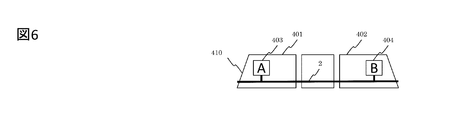
図6は、運用する編成が1列車で構成される例を示す図である。
列車410の運行開始時、運転士等が列車の進行方向の先頭車両に搭乗し、マスターキーなどを用いて運転台を選択する。この場合、列車410において、運転士等により選択された側の車両を先頭車両401とし、搭載された車上装置を車上装置A(403)とする。また、先頭車両401とは進行方向反対側の車両を後端車両402とし、搭載された車上装置を車上装置B(404)とする。 FIG. 6 is a diagram showing an example in which the train set to be operated is composed of one train.
At the start of operation of thetrain 410, a driver or the like boards a leading vehicle in the traveling direction of the train and selects a driver's cab using a master key or the like. In this case, in the train 410, the vehicle on the side selected by the driver or the like is the leading vehicle 401, and the installed onboard device is the onboard device A (403). Further, a vehicle on the opposite side of the leading vehicle 401 in the traveling direction is referred to as a rear end vehicle 402, and the mounted on-board device is referred to as an on-board device B (404).
列車410の運行開始時、運転士等が列車の進行方向の先頭車両に搭乗し、マスターキーなどを用いて運転台を選択する。この場合、列車410において、運転士等により選択された側の車両を先頭車両401とし、搭載された車上装置を車上装置A(403)とする。また、先頭車両401とは進行方向反対側の車両を後端車両402とし、搭載された車上装置を車上装置B(404)とする。 FIG. 6 is a diagram showing an example in which the train set to be operated is composed of one train.
At the start of operation of the
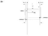
図7は、車上装置A(403)と車上装置B(404)との間の通信手順を説明する図である。
列車410内の各車上装置AとBは、電源投入直後や運用前の段階で運転台が選択されていない状態では、スタンバイモード501となる。 FIG. 7 is a diagram illustrating a communication procedure between the on-board device A (403) and the on-board device B (404).
The on-board devices A and B in thetrain 410 are in the standby mode 501 immediately after the power is turned on or when the driver's cab is not selected immediately before the operation.
列車410内の各車上装置AとBは、電源投入直後や運用前の段階で運転台が選択されていない状態では、スタンバイモード501となる。 FIG. 7 is a diagram illustrating a communication procedure between the on-board device A (403) and the on-board device B (404).
The on-board devices A and B in the
運転士等が車上装置Aを搭載した運転台を選択した場合、車上装置Aは、運転台から運転台選択条件を受信する。この際、車上装置Aの列車完全性監視部は、編成サーチモード502に遷移する。
When the driver or the like selects the cab equipped with the onboard device A, the onboard device A receives the cab selection condition from the cab. At this time, the train integrity monitoring unit of the on-board device A transits to the formation search mode 502.
編成サーチモード502において、車上装置Aは、伝送ライン2を介して編成内の車上装置にメッセージ601を送信する。車上装置Bは、伝送ライン2からメッセージ601を受信し、車上装置Bの列車完全性監視部も同じく編成サーチモード502に遷移する。そして、車上装置Bは、自身のIDを付与した確認のメッセージ602を伝送ライン2に送信する。
In the composition search mode 502, the onboard device A transmits a message 601 to the onboard device in the composition via the transmission line 2. The onboard device B receives the message 601 from the transmission line 2, and the train integrity monitoring unit of the onboard device B also transits to the formation search mode 502. Then, the on-board device B transmits a confirmation message 602 with its own ID attached to the transmission line 2.
車上装置Aは、車上装置Bからのメッセージ602を受信することで、編成の後端に車上装置Bが搭載されていること認識する。この後、車上装置Aは、編成の確定を意味するメッセージ603を車上装置Bに向けて送信する。
By receiving the message 602 from the onboard device B, the onboard device A recognizes that the onboard device B is mounted at the rear end of the formation. After that, the on-board device A sends a message 603, which means the confirmation of the formation, to the on-board device B.
車上装置Bは、メッセージ603を受信することで完全性確立モード503に遷移し、車上装置Aに向けて完全性確立へ遷移した旨のメッセージ604を送信する。
Upon receiving the message 603, the on-board device B transits to the integrity establishment mode 503, and sends to the on-board device A a message 604 indicating the transition to the integrity establishment.
車上装置Aは、メッセージ104を受信することで完全性確立モード503に遷移する。車上装置Aは、完全性確立モード503に遷移した後、一定の周期でメッセージ605を伝送ライン2に送信する。
The on-board device A transitions to the integrity establishment mode 503 upon receiving the message 104. After the transition to the integrity establishment mode 503, the on-board device A transmits the message 605 to the transmission line 2 at a constant cycle.
車上装置Bは、定期的に送られるメッセージ605に対して確認のメッセージ606を送信する。車上装置Aは、定期的に送信するメッセージ605に対して返信されるメッセージ606を確認する。これにより、編成内の列車が接続状態にあり列車完全性が確立される。車上装置Aおよび車上装置Bそれぞれの列車完全性監視部は、完全性確立モード503を保つ。
The on-board device B sends a confirmation message 606 to the message 605 sent periodically. The on-board device A confirms the message 606 returned in response to the message 605 that is periodically transmitted. This establishes the train integrity of the trains in the formation and establishes train integrity. The train integrity monitoring units of the on-board device A and the on-board device B maintain the integrity establishment mode 503.
列車完全性が確立された状態で列車運行を完了する場合には、運転士等が運転台選択を解除する。これにより、車上装置Aは、メッセージ605の送信を止め、完全性チェックの停止を意味するメッセージ607を伝送ライン2に送信する。
When the train operation is completed with the train integrity established, the driver etc. cancels the cab selection. As a result, the on-board device A stops the transmission of the message 605 and transmits the message 607 indicating the stop of the integrity check to the transmission line 2.
車上装置Bは、このメッセージ607を受信してスタンバイモード501に遷移し、完全性チェック完了の確認メッセージ608を車上装置Aに送信する。車上装置Aは、メッセージ608を受信するとスタンバイモード501に遷移する。
The on-board device B receives this message 607, transitions to the standby mode 501, and transmits the integrity check completion confirmation message 608 to the on-board device A. Upon receiving the message 608, the on-board device A transitions to the standby mode 501.
図8は、図6で示す列車410が分断された場合を示す図である。図9は、分断された場合の車上装置Aと車上装置Bとの間の通信手順を説明する図である。
列車410が走行中で車両が分断される前は、図7に示すように列車完全性が確立されている。 FIG. 8 is a diagram showing a case where thetrain 410 shown in FIG. 6 is divided. FIG. 9 is a diagram illustrating a communication procedure between the on-board device A and the on-board device B in the case of being divided.
Before thetrain 410 is running and the vehicle is divided, train integrity is established as shown in FIG. 7.
列車410が走行中で車両が分断される前は、図7に示すように列車完全性が確立されている。 FIG. 8 is a diagram showing a case where the
Before the
列車410内の車両が走行中に分断された場合、伝送ライン2も分断されるため、車上装置Bは、車上装置Aが定期的に送信するメッセージ605を受信できない。このため、車上装置Aも、車上装置Bからの確認メッセージ606を一定時間受信できない。これにより、車上装置Aの列車完全性監視部は列車の完全性が失われたものと判断し、車上装置Aは完全性喪失モード504に遷移する。
When the vehicle in the train 410 is divided while the vehicle is running, the transmission line 2 is also divided, and therefore the onboard device B cannot receive the message 605 that the onboard device A regularly transmits. Therefore, the on-board device A cannot receive the confirmation message 606 from the on-board device B for a certain period of time. As a result, the train integrity monitoring unit of the on-board device A determines that the integrity of the train has been lost, and the on-board device A transitions to the integrity loss mode 504.
完全性喪失モード504に遷移した場合、車上装置Aは、自身の保安装置の規定や制御方式に従い、列車完全性の喪失を地上装置に報告する。この際、列車完全性の喪失は、運転台に設置された表示器(図2の表示器105)などを通じて運転士等に通知される。
When transitioning to the integrity loss mode 504, the onboard device A reports the loss of train integrity to the ground device in accordance with the rules and control method of its own security device. At this time, the loss of train integrity is notified to the driver or the like through a display device (display device 105 in FIG. 2) installed in the cab.
また、車上装置Bも、車上装置Aからのメッセージ605を一定時間受信できないことから、車上装置Bの列車完全性監視部も同じく完全性喪失モード504に遷移する。
Also, since the onboard device B cannot receive the message 605 from the onboard device A for a certain period of time, the train integrity monitoring unit of the onboard device B also transits to the integrity loss mode 504.
ここで、分断した車両に搭載された車上装置Bの扱いは、保安装置や列車運行の規定に従うことになる。しかし、車上装置Bを搭載した車両402は、後続列車の運行の妨げとなる。そのため、車両の場所の特定と路線運用上の対処との早期実施を目的として、列車の位置と完全性喪失との情報を地上装置に報告することもできる。
Here, the handling of the on-board device B mounted on the divided vehicle will be in accordance with the regulations of the safety device and train operation. However, the vehicle 402 equipped with the on-board device B interferes with the operation of the succeeding train. Therefore, it is possible to report information on the position of the train and loss of integrity to the ground device for the purpose of early implementation of the location of the vehicle and countermeasures for route operation.
列車410が停止に至った場合、車上装置Aにおいて、運転士等が表示器(図2の表示器105)を通じて確認し、マスターキーの解除などを行う。これにより、車上装置Aは、完全性喪失モード504が解除され、スタンバイモード501に遷移する。車上装置Bについても、運転士等が表示器(図2の表示器105)を通じて確認し、マスターキーの解除などを行う。これにより、車上装置Bも、スタンバイモード501に遷移する。
When the train 410 comes to a stop, in the onboard device A, the driver or the like confirms through the display (display 105 in FIG. 2) and releases the master key. As a result, the on-board device A releases the integrity loss mode 504 and transitions to the standby mode 501. With respect to the on-board device B, a driver or the like checks the display device (display device 105 in FIG. 2) and releases the master key. As a result, the on-board device B also transitions to the standby mode 501.
図10は、運用する編成が2列車で構成される例を示す図である。
連結する2列車のうち、進行方向側にある列車a(710)および後端側にある列車b(711)それぞれは、図1に示す列車の構成を有する。 FIG. 10 is a diagram showing an example in which the train set to be operated is composed of two trains.
Of the two connected trains, the train a (710) on the traveling direction side and the train b (711) on the rear end side each have the train configuration shown in FIG. 1.
図10に示すように、列車aの先端側で、運転士等により選択される先頭車両701は、車上装置A(705)を搭載する。列車aの後端側の車両702は、車上装置B(706)を搭載する。列車bの先頭側の車両703は、車上装置C(707)を搭載する。列車bの後端側で、編成の最後端の車両704は、車上装置D(708)を搭載する。
As shown in FIG. 10, a leading vehicle 701 selected by a driver or the like on the tip side of the train a is equipped with an on-board device A (705). The vehicle 702 on the rear end side of the train a is equipped with the on-board device B (706). The vehicle 703 on the leading side of the train b is equipped with the on-board device C (707). On the rear end side of the train b, the vehicle 704 at the rearmost end of the train is equipped with the on-board device D (708).
列車aおよび列車bは、車両702と車両703とにおいて連結器709により連結される。また、伝送ライン2が、連結器709を介して各列車の先頭車両から後端車両まで引き通され、互いの列車情報を通信可能にする。
Train a and train b are connected by a connector 709 in a vehicle 702 and a vehicle 703. In addition, the transmission line 2 is drawn from the leading vehicle to the trailing vehicle of each train via the coupler 709 to enable mutual communication of train information.
また、列車aおよび列車bは、連結時に車両の連結状態を通知する機構を有する。具体的には、連結器709が、車両連結を示す情報(以下、「車両連結情報」という)を、連結器を709を備える車両702と車両703それぞれの車上装置に通知する。これにより、各車上装置は、自らを搭載した車両が連結状態にあるか否かを検知することができる。
Also, trains a and b have a mechanism for notifying the connection state of vehicles at the time of connection. Specifically, the coupler 709 notifies the information indicating the vehicle coupling (hereinafter, referred to as “vehicle coupling information”) to the on-board devices of the vehicle 702 and the vehicle 703 each including the coupler 709. Thereby, each on-board device can detect whether or not the vehicle on which the device is mounted is in the connected state.
図11は、図10に示す編成の場合の通信手順を説明する図である。
運転士等が運転台を選択した場合、図6に示す例と同様に、車上装置Aは、運転台から運転台選択条件を受信し、スタンバイモード501から編成サーチモード502に遷移する。この際、車上装置Aは、伝送ライン2を介して編成内の車上装置に向けてメッセージ601を送信する。 FIG. 11 is a diagram illustrating a communication procedure in the case of the organization shown in FIG.
When the driver or the like selects the driver's cab, the on-board device A receives the driver's cab selection condition from the driver's cab and transitions from thestandby mode 501 to the formation search mode 502, as in the example shown in FIG. 6. At this time, the on-board device A transmits the message 601 to the on-board device in the formation via the transmission line 2.
運転士等が運転台を選択した場合、図6に示す例と同様に、車上装置Aは、運転台から運転台選択条件を受信し、スタンバイモード501から編成サーチモード502に遷移する。この際、車上装置Aは、伝送ライン2を介して編成内の車上装置に向けてメッセージ601を送信する。 FIG. 11 is a diagram illustrating a communication procedure in the case of the organization shown in FIG.
When the driver or the like selects the driver's cab, the on-board device A receives the driver's cab selection condition from the driver's cab and transitions from the
車上装置B、CおよびDは、車上装置Aからのメッセージ601を受信する。この内、車上装置BおよびCは、車両連結情報を連結器709から受信しているため、当該車両702および703は、後端車両にはなり得ない。これにより、車上装置BおよびCは、メッセージ601を受信してもこれを無視してスタンバイモード501を保つ。
The on-board devices B, C and D receive the message 601 from the on-board device A. Among these, since the on-board devices B and C have received the vehicle connection information from the connector 709, the vehicles 702 and 703 cannot be rear-end vehicles. As a result, the on-board devices B and C ignore the message 601 even if it receives the message 601, and maintain the standby mode 501.
一方、車上装置Dは、自身のIDを付与したメッセージ602を伝送ライン2に送信する。車上装置Aは、車上装置Dからのメッセージ602を受信することで編成後端の車上装置Dを認識する。
On the other hand, the on-board device D transmits the message 602 with its own ID to the transmission line 2. The on-board device A recognizes the on-board device D at the rear end of the formation by receiving the message 602 from the on-board device D.
車上装置Aは、メッセージ603を車上装置Dに向けて送信する。車上装置Dは、メッセージ603を受信することで完全性確立モード503に遷移し、車上装置Aに向けてメッセージ604を送信する。車上装置Aは、メッセージ604を受信することで完全性確立モード503に遷移する。
The onboard device A sends a message 603 to the onboard device D. Upon receiving the message 603, the on-board device D transits to the integrity establishing mode 503 and transmits the message 604 to the on-board device A. The on-board device A transitions to the integrity establishment mode 503 upon receiving the message 604.
以上のとおり、後端車両が搭載する車上装置Dのみが車上装置Aと通信を行うことにより、編成の列車完全性を確立させる。
As described above, only the onboard device D mounted on the rear end vehicle communicates with the onboard device A to establish the train integrity of the formation.
車上装置BまたはCが、何らかの異常により車上装置Aにメッセージ602もしくは他のメッセージを送信をした場合、車上装置Aは、受信したメッセージ内のIDや手順の誤りから異常を検知する。この場合、列車完全性は確立せず、スタンバイモード501もしくは完全性喪失モード504となる。以降の動作は、1列車編成時における動作と同じである。
When the on-board device B or C sends the message 602 or another message to the on-board device A due to some abnormality, the on-board device A detects the abnormality from the ID in the received message or the error in the procedure. In this case, the train integrity is not established and the standby mode 501 or the integrity loss mode 504 is set. The subsequent operations are the same as the operations when one train is formed.
編成が3列車以上で構成される場合においても、編成内の車上装置が搭載された車両は編成内で1両のみに決定される先頭車両および後端車両、さらにその他の連結車両の3種類に分けられる。列車完全性の監視は、上述した2列車編成時と同じ動作で実現可能である。
Even when the train consists of three or more trains, the number of vehicles equipped with the on-board device in the train is determined to be only one in the train, the leading car and the rear-end car, and three other types of connected cars. Divided into The monitoring of train integrity can be realized by the same operation as the above-mentioned two-train formation.
図12は、1列車編成同士が連結され1つの編成を構成する例を示す図である。
図に示す状態においては、2つの編成それぞれは列車完全性を保っている。連結される列車内の構成は、図8と同様とする。列車711が列車710に向けて接近し、連結時は車両701および703が運転士等により選択される。 FIG. 12 is a diagram showing an example in which one train set is connected to each other to form one set.
In the situation shown, each of the two train sets maintains train integrity. The configuration of the connected trains is the same as in FIG. Thetrain 711 approaches the train 710, and at the time of connection, the vehicles 701 and 703 are selected by a driver or the like.
図に示す状態においては、2つの編成それぞれは列車完全性を保っている。連結される列車内の構成は、図8と同様とする。列車711が列車710に向けて接近し、連結時は車両701および703が運転士等により選択される。 FIG. 12 is a diagram showing an example in which one train set is connected to each other to form one set.
In the situation shown, each of the two train sets maintains train integrity. The configuration of the connected trains is the same as in FIG. The
図13は、図12に示す状態の場合の通信手順を説明する図である。
連結前の各車上装置は、完全性確立モード503にある。列車711が列車710に接近して連結される際、車上装置BおよびCは、互いの列車の伝送ライン2が接続される前に連結器709から車両連結情報を得る。 FIG. 13 is a diagram illustrating a communication procedure in the case of the state shown in FIG.
Each on-board device before connection is in theintegrity establishment mode 503. When the train 711 is closely connected to the train 710, the on-board devices B and C obtain the vehicle connection information from the connector 709 before the transmission line 2 of each train is connected.
連結前の各車上装置は、完全性確立モード503にある。列車711が列車710に接近して連結される際、車上装置BおよびCは、互いの列車の伝送ライン2が接続される前に連結器709から車両連結情報を得る。 FIG. 13 is a diagram illustrating a communication procedure in the case of the state shown in FIG.
Each on-board device before connection is in the
車上装置Bは、連結中を意味するメッセージ609を車上装置Aに送信してスタンバイモード501に遷移する。車上装置Aは、メッセージ609を受信すると、編成サーチモード502に遷移し、メッセージ601を定期的に一定時間伝送ライン2に送信する。
The on-board device B sends a message 609 indicating that the connection is in progress to the on-board device A and transitions to the standby mode 501. Upon receiving the message 609, the on-board device A transits to the composition search mode 502, and periodically transmits the message 601 to the transmission line 2 for a certain period of time.
一方、車上装置Cは、連結中を意味するメッセージ610を車上装置Dに送信してスタンバイモード501に遷移する。車上装置Dは、メッセージ610を受信してスタンバイモード501に遷移する。
On the other hand, the on-board device C transmits a message 610, which means that the vehicle is connected, to the on-board device D and transitions to the standby mode 501. The on-board device D receives the message 610 and transitions to the standby mode 501.
列車間の伝送ライン2が接続された後、車上装置Dは、車上装置Aからのメッセージ601を受信する。以降の列車完全性を確立する手順は、2列車で構成される編成が列車完全性を確認する手順と同じである。
After the transmission line 2 between the trains is connected, the onboard device D receives the message 601 from the onboard device A. The subsequent procedure for establishing train integrity is the same as the procedure for confirming train integrity for a train consisting of two trains.
以上のように、連結時には運転士等の介在なく列車完全性を確認することができる。2列車以上で構成される編成の連結においても、列車完全性の監視は、先に示した2列車編成の場合と同じ動作で実現可能である。
As mentioned above, train integrity can be confirmed without intervening driver when connecting. Even in the case of connecting a train consisting of two or more trains, the monitoring of train integrity can be realized by the same operation as in the case of the above-mentioned two trains.
図14は、2列車編成が運行中に1列車編成ずつに分割される例を示す図である。この場合には、1編成を2列車に意図的に分割する場合と、走行中に意図することなく分断される場合とを含む。
FIG. 14 is a diagram showing an example in which two train sets are divided into one train set during operation. In this case, a case where one train is intentionally divided into two trains and a case where the train is unintentionally divided during traveling are included.
図15は、図14に示す状態の場合の通信手順を説明する図である。
分割前の編成は、列車完全性を保っている。列車が分割された場合、連結器が離れ、車上装置BおよびCは車両連結情報を喪失する。これにより、列車間の伝送ライン2が分断される。 FIG. 15 is a diagram illustrating a communication procedure in the case of the state shown in FIG.
The train before division maintains train integrity. When the train is split, the coupler is released and the on-board devices B and C lose the vehicle connection information. As a result, thetransmission line 2 between the trains is divided.
分割前の編成は、列車完全性を保っている。列車が分割された場合、連結器が離れ、車上装置BおよびCは車両連結情報を喪失する。これにより、列車間の伝送ライン2が分断される。 FIG. 15 is a diagram illustrating a communication procedure in the case of the state shown in FIG.
The train before division maintains train integrity. When the train is split, the coupler is released and the on-board devices B and C lose the vehicle connection information. As a result, the
車上装置Bは、車両連結情報の喪失によりメッセージ611を伝送ライン2に送信する。車上装置Aは、車上装置Bからのメッセージ611を受信し、完全性喪失モード504に遷移する。
The on-board device B transmits the message 611 to the transmission line 2 due to the loss of the vehicle connection information. Onboard device A receives message 611 from onboard device B and transitions to loss of integrity mode 504.
車上装置Aは、自身の保安装置の規定に従い、完全性喪失を地上装置に報告する。車上装置Aは、編成の分割が意図したものかどうかを判断できない。そのため、車上装置Aは、運転士等に対して完全性喪失を表示器((図2の表示器105))を通じて表示し、確認を要求する。
On-board device A reports the loss of integrity to the ground device in accordance with the rules of its own security device. The on-board device A cannot determine whether or not the division of the formation is intended. Therefore, the on-board device A displays the loss of integrity to the driver or the like through the display ((display 105 in FIG. 2)) and requests confirmation.
列車が停車している場合もしくは走行中から停車に至った場合、運転士等の確認と分割後の総列車長の変更とから、車上装置Aは、完全性喪失モード504を解除して編成サーチモード502に遷移する。ただし、列車が走行している場合は、完全性喪失モード504を保持する。
When the train is stopped or when it is stopped while running, the on-board device A releases the integrity loss mode 504 from the confirmation of the driver etc. and the change of the total train length after the division. Transition to the search mode 502. However, the integrity loss mode 504 is maintained when the train is running.
車上装置Aは、編成サーチモード502に遷移後、メッセージ601を伝送ライン2に送信する。車上装置Bは、メッセージ601を受信した後メッセージ602を車上装置Aに送信する。また、車上装置CおよびDを備える編成の方の通信手順も同様である。以降の手順は、1列車編成における通信手順と同じである。
The on-board device A transmits the message 601 to the transmission line 2 after transitioning to the composition search mode 502. After receiving the message 601, the on-board device B transmits the message 602 to the on-board device A. The same applies to the communication procedure for the formation including the on-board devices C and D. The subsequent procedure is the same as the communication procedure for one train set.
図16は、2列車編成が列車の連結面ではない車両で分断される例を示す図である。図では、列車711内の車両704で分断される場合を示す。
FIG. 16 is a diagram showing an example in which a two-train formation is divided by a vehicle that is not a connecting surface of trains. The figure shows a case where the vehicle 704 in the train 711 divides the train.
図17は、図16に示す状態の場合の通信手順を説明する図である。
列車の進行方向に対して後端側の列車711内で分断が発生した場合、図9と同様に、車上装置Aは、車上装置Dからのメッセージ606が一定時間受信されないことから、完全性喪失モード504に遷移する。 FIG. 17 is a diagram for explaining the communication procedure in the case of the state shown in FIG.
When a division occurs in thetrain 711 on the rear end side with respect to the traveling direction of the train, the onboard device A does not receive the message 606 from the onboard device D for a certain period of time as in FIG. Transition to the sex loss mode 504.
列車の進行方向に対して後端側の列車711内で分断が発生した場合、図9と同様に、車上装置Aは、車上装置Dからのメッセージ606が一定時間受信されないことから、完全性喪失モード504に遷移する。 FIG. 17 is a diagram for explaining the communication procedure in the case of the state shown in FIG.
When a division occurs in the
また、車上装置Dは、車上装置Aからのメッセージ605が一定時間受信されないことから、完全性喪失モード504に遷移する。この場合、図15に示す通信手順に従い、運転士等が確認し、車上装置Aが再度編成サーチモード502に遷移したとしても、車上装置BおよびCは、連結車両であるためメッセージ605を破棄する。また、車上装置Dは、分断されているため応答ができないため、列車完全性は確立されない。
Further, the on-board device D transits to the integrity loss mode 504 because the message 605 from the on-board device A is not received for a certain period of time. In this case, according to the communication procedure shown in FIG. 15, even if the driver or the like confirms and the on-board device A transitions to the formation search mode 502 again, the on-board devices B and C are connected vehicles, and therefore the message 605 is displayed. Discard. Further, since the on-board device D is divided and cannot respond, train integrity is not established.
車上装置を搭載した列車が自動運転機能を備え、列車の運用に運転士等が必要とされない場合(すなわち、無人運転)において、車両の選択状態として進行方向の先頭車両から状態を示す入力を得る。これにより、同じ手順を用いて運転台の選択条件を制御することが可能である。この場合、列車の分断などにより運転士等の確認が必要な手順については、地上装置との無線通信を介して地上装置からの指示により代用が可能である。
When a train equipped with an on-board device has an automatic driving function and a driver or the like is not required to operate the train (that is, unmanned driving), an input indicating the state from the leading vehicle in the traveling direction is input as the vehicle selection state. obtain. This makes it possible to control the driver's cab selection conditions using the same procedure. In this case, the procedure that requires confirmation by the driver or the like due to division of the train or the like can be substituted by an instruction from the ground device via wireless communication with the ground device.
車上装置や完全性監視機能に故障が発生した場合は、以下の手順を採用する。
先頭車両の車上装置が故障した場合、当該編成は車上装置を用いた制御ができないため、以降の運用では列車完全性情報は用いられない。以降の運用に関しては、路線の運用規定に基づくこととなる。 In case of failure of on-board equipment or integrity monitoring function, the following procedure is adopted.
If the on-board device of the leading vehicle fails, the train cannot be controlled using the on-board device, and train integrity information is not used in the subsequent operations. Subsequent operations will be based on the operational rules of the route.
後端車両の車上装置の故障や通信経路(伝送ライン)の分断などの異常が発生した場合、故障した車上装置は伝送ラインから切り離され、以降のメッセージ606は送信されない。このため、先頭車両は列車完全性が喪失したものとして判断する。列車が分断されていないにも拘らず列車完全性の喪失が報告されるため、運用上に不都合が生じる可能性がある。しかし、実際に列車完全性が喪失しているにも拘らず、列車完全性の確立を報告するという誤った情報を地上装置に送付することは回避できる。この場合、運転士等により車上装置の故障が確認され、運用上の規定に従い、以降の編成の運用が判断されることになる。
If an abnormality such as a failure of the on-board device of the rear-end vehicle or disconnection of the communication path (transmission line) occurs, the failed on-board device is disconnected from the transmission line, and the subsequent message 606 is not sent. Therefore, the leading car is judged to have lost the train integrity. Loss of train integrity is reported despite undivided trains, which can result in operational inconvenience. However, it is possible to avoid sending erroneous information to the ground equipment that reports the establishment of train integrity, despite the fact that the train integrity is actually lost. In this case, the driver or the like confirms that the on-board device is out of order, and the subsequent operation of the formation is determined according to the operational regulations.
先で定義した機能およびモードは、列車完全性確認機能と列車完全性情報との扱い、および列車完全性の地上装置への報告などに使用される。よって、車上装置の制御に関する他の機能や制御モードには影響を与えない。
The functions and modes defined above are used for handling the train integrity confirmation function and train integrity information, and for reporting the train integrity to the ground equipment. Therefore, it does not affect other functions and control modes related to the control of the on-board device.
また、列車が分断された状態の保安装置の運用規定や路線の運用ルールなどにより、完全性喪失モード504の解除条件を変更してもよい。例として、車上装置から地上装置への列車完全性喪失に対する地上装置からの確認メッセージの受信などが挙げられる。
Also, the cancellation condition of the integrity loss mode 504 may be changed according to the operational regulations of the security device in the state where the train is divided and the operational rules of the route. An example would be the receipt of a confirmation message from the ground equipment for loss of train integrity from the onboard equipment to the ground equipment.
次に、列車を編成する車両の状態と車上装置の動作状態との関係について説明する。
図2に示すように、車上装置107は、少なくとも次の3種類の認識手段を有する。3種類の認識手段は、マスター認識手段154、併結認識手段155および指令認識手段156である。これら3種類の認識手段からの入力内容に応じて、列車完全性監視部151による動作が制御される。 Next, the relationship between the state of the vehicle forming the train and the operating state of the on-board device will be described.
As shown in FIG. 2, the on-board device 107 has at least the following three types of recognition means. The three types of recognition means are a master recognition means 154, a concatenation recognition means 155, and a command recognition means 156. The operation of the train integrity monitoring unit 151 is controlled according to the input contents from these three types of recognition means.
図2に示すように、車上装置107は、少なくとも次の3種類の認識手段を有する。3種類の認識手段は、マスター認識手段154、併結認識手段155および指令認識手段156である。これら3種類の認識手段からの入力内容に応じて、列車完全性監視部151による動作が制御される。 Next, the relationship between the state of the vehicle forming the train and the operating state of the on-board device will be described.
As shown in FIG. 2, the on-
マスター認識手段154は、マスター権限を認識する。併結認識手段155は、自身の車両に紐づけられた併結状態を監視し認識する。指令認識手段156は、列車が運行を目的として動作(in service)を指示されているか否(out of service)かを認識する。
The master recognition means 154 recognizes the master authority. The merging/recognizing means 155 monitors and recognizes the merging state associated with the own vehicle. The command recognition unit 156 recognizes whether or not the train is instructed to operate (in service) for the purpose of running (out of service).
図18は、マスター認識手段154、併結認識手段155および指令認識手段156による設定および車上装置の動作状態との関係を示す図である。
マスター認識の欄で、「1」はマスター設定、「0」は非マスター設定、であることを示す。
併結認識の欄で、「1」は併結状態であること、「0」は併結状態でないこと、を示す。
指令認識の欄で、「1」は運行指令が出されていること、「0」は運行指令が出されていないこと(例えば、車両基地や側線等における入換操作の指令が出されている状態)、を示す。 FIG. 18 is a diagram showing the relationship between the setting by the master recognizing means 154, themerge recognizing means 155, and the command recognizing means 156 and the operating state of the on-board device.
In the column of master recognition, "1" indicates master setting and "0" indicates non-master setting.
In the merge recognition column, "1" indicates that the merge is in effect, and "0" indicates that the merge is not in effect.
In the command recognition column, "1" indicates that an operation command has been issued, and "0" indicates that an operation command has not been issued (for example, a replacement operation command at a vehicle depot or a lateral line has been issued. State).
マスター認識の欄で、「1」はマスター設定、「0」は非マスター設定、であることを示す。
併結認識の欄で、「1」は併結状態であること、「0」は併結状態でないこと、を示す。
指令認識の欄で、「1」は運行指令が出されていること、「0」は運行指令が出されていないこと(例えば、車両基地や側線等における入換操作の指令が出されている状態)、を示す。 FIG. 18 is a diagram showing the relationship between the setting by the master recognizing means 154, the
In the column of master recognition, "1" indicates master setting and "0" indicates non-master setting.
In the merge recognition column, "1" indicates that the merge is in effect, and "0" indicates that the merge is not in effect.
In the command recognition column, "1" indicates that an operation command has been issued, and "0" indicates that an operation command has not been issued (for example, a replacement operation command at a vehicle depot or a lateral line has been issued. State).
車上装置による動作内容は、各認識手段からの入力内容(設定内容)の組み合わせによって決定される。
マスター認識が「1」、併結認識が「0」および指令認識が「1」であれば、車上装置は、「運行状態」、「列車の端部」かつ「走行方向における先頭車両」にあることを認識する。そして車上装置は、マスター機器(状態)として動作し、必要なメッセージの送信を行う。 The operation content by the on-board device is determined by a combination of the input content (setting content) from each recognition means.
If the master recognition is "1", the merge recognition is "0", and the command recognition is "1", the on-board device is in the "operational state", the "end of the train", and the "leading vehicle in the traveling direction". Recognize that. Then, the on-board device operates as a master device (state) and transmits a necessary message.
ただし、マスター認識が「1」、併結認識が「0」であっても、指令認識が「0」であれば、車上装置は、マスター機器(状態)ではあるが運行状態ではない(運行外である)場合になる。
However, even if the master recognition is “1” and the concatenation recognition is “0”, if the command recognition is “0”, the on-board device is the master device (state) but not in the operation state (outside the operation). That is the case).
マスター認識が「0」、併結認識が「0」である場合、車上装置は、マスター機器(状態)である他の車上装置からメッセージを受信する、または、同一列車内の他の車両をマスター状態と認識することで、スレーブ機器(状態)として動作する。すなわち、車上装置は、「列車の端部」かつ「走行方向における後端車両」にあることを認識する。これにより、車上装置は、マスター機器(状態)である他の車上装置から送信されるメッセージに対して応答メッセージを送信する。
When the master recognition is “0” and the merge recognition is “0”, the on-board device receives a message from another on-board device that is the master device (state), or another vehicle in the same train is notified. By recognizing the master state, it operates as a slave device (state). That is, the on-board device recognizes that it is at the “end of the train” and at the “rear end vehicle in the traveling direction”. As a result, the on-board device transmits a response message in response to a message transmitted from another on-board device that is the master device (state).
マスター認識が「0」かつ併結認識が「1」である場合、車上装置は、自身の車両が運行状態でかつ中間車両として配置されていることを認識する。すなわち、車上装置は、サイレント機器(状態)として動作し、併結認識が「1」である間、マスター機器(状態)やスレーブ機器(状態)である他の車上装置から送信されるメッセージに対して応答しない。
When the master recognition is “0” and the consolidation recognition is “1”, the on-board device recognizes that its own vehicle is in operation and is arranged as an intermediate vehicle. That is, the on-board device operates as a silent device (state), and while the concatenation recognition is “1”, a message transmitted from another on-board device that is a master device (state) or a slave device (state) is displayed. Do not respond to.
以上で説明した3つの状態は、運行状態にある車上装置の基本的な動作である。
なお、各認識手段からの入力内容(設定内容)の組み合わせは他にも存在するが、それらは原則として異常検出状態として処理する。例えば、マスター認識が「1」、併結認識が「1」および指令認識が「1」である場合は、列車の中間車両から運転操作を実行する特殊な場合を除き、異常検出状態として扱われる。 The three states described above are the basic operations of the on-board device in the operating state.
Although there are other combinations of input contents (setting contents) from the respective recognizing means, they are processed as an abnormality detection state in principle. For example, when the master recognition is “1”, the concatenation recognition is “1”, and the command recognition is “1”, it is treated as an abnormality detection state except for a special case where a driving operation is performed from an intermediate vehicle of a train.
また、指令認識が「0」の場合とは、例えば、列車が車両基地や側線に有り、編成の併結や分割などの入換操作時にのみ設定可能である。さらにまた、指令認識の設定として、特に「0」から「1」に設定する場合は、安全性を高める必要があることに留意が必要である。すなわち、切替えの運用手続きにおいて、運転士等による確認操作、地上装置との通信の組み込み、列車が停止状態であること、を条件とすることが望ましい。
Also, when the command recognition is “0”, for example, the train is located at the depot or side track, and it can be set only when a replacement operation such as merging or splitting a formation is performed. Furthermore, it is necessary to pay attention to the fact that the safety needs to be improved when setting “0” to “1” as the command recognition setting. In other words, it is desirable that the operation procedure for switching includes the condition that a confirmation operation by a driver or the like, the incorporation of communication with a ground device, and that the train is stopped.
次に、それぞれの認識手段の詳細について説明する。
(a)マスター認識手段154
マスター認識手段154は、車上装置107の制御部106に対してマスター設定または非マスター設定の指示を与える機能を有する。この実現のために、例えば、運転台を動作させるためのマスターキー、運転台に設置した専用ボタン、生体認証装置、または運転台が備える表示器に表示される専用の設定画面などを用いることができる。 Next, the details of each recognition means will be described.
(A) Master recognition means 154
Themaster recognition unit 154 has a function of giving an instruction of master setting or non-master setting to the control unit 106 of the on-board device 107. To achieve this, it is possible to use, for example, a master key for operating the driver's cab, a dedicated button installed on the driver's cab, a biometric authentication device, or a dedicated setting screen displayed on an indicator provided in the driver's cab. it can.
(a)マスター認識手段154
マスター認識手段154は、車上装置107の制御部106に対してマスター設定または非マスター設定の指示を与える機能を有する。この実現のために、例えば、運転台を動作させるためのマスターキー、運転台に設置した専用ボタン、生体認証装置、または運転台が備える表示器に表示される専用の設定画面などを用いることができる。 Next, the details of each recognition means will be described.
(A) Master recognition means 154
The
また、マスター認識手段154は、運転士等が列車に搭乗し、操作する運転台を選択するときに併せて動作する。マスター認識手段154は、運転士等の指示入力を受け取ると、マスター設定の指示に従って、自身の車上装置がマスター機器(状態)であることを認識する。ここで、列車が無人運転などの場合には、地上装置からの指示に従って列車の進行方向の運転台が決定した際に、マスター設定の指示が出力される構成としてもよい。
Further, the master recognition means 154 also operates when a driver or the like boards a train and selects a driver's cab to be operated. Upon receiving an instruction input from a driver or the like, the master recognizing unit 154 recognizes that its own on-board device is a master device (state) according to an instruction for master setting. Here, when the train is an unmanned operation, the master setting instruction may be output when the cab in the traveling direction of the train is determined according to the instruction from the ground device.
マスター機器(状態)である車上装置による動作態様を、図6に示す例で以て説明する。車上装置Aは、起動時においてスタンバイモード501である。マスター認識手段154がマスター設定指令を出力することによって、車上装置Aは、編成サーチモード502へ遷移し、マスター機器(状態)としてメッセージ601を送信することが可能となる。
The operation mode of the on-board device that is the master device (state) will be described with reference to the example shown in FIG. The on-board device A is in the standby mode 501 at startup. When the master recognition unit 154 outputs the master setting command, the on-board device A can transit to the formation search mode 502 and transmit the message 601 as the master device (state).
なお、列車編成を構成する車両群の中の一車両の車上装置のみが、マスター認識を「1」とすることが許される。車両に対するインターロックなどを用いて、マスター認識は編成内の一車両のみに指令される構成となる。一方で、マスター機器(状態)となった車上装置からメッセージを受け取った他の車上装置は、自身のマスター認識手段154の動作を禁止する。このように、編成中に複数のマスター機器(状態)が発生しないように制御してもよい。
Note that only the on-board device of one of the trains forming the train set is allowed to have the master recognition as "1". Master recognition is configured to be instructed to only one vehicle in the formation by using an interlock for the vehicle. On the other hand, another on-board device that has received the message from the on-board device that has become the master device (state) prohibits the operation of its own master recognition means 154. In this way, control may be performed so that a plurality of master devices (states) do not occur during knitting.
もし、併結の解除または新規の併結が運行状態にある列車に求められる場合(換言すると、スレーブ機器(状態)またはサイレント機器(状態)にある車上装置をマスター機器(状態)に切り替えることが必要な場合)は、特別に専用の手続によってマスター機器(状態)の設定を可能とすることが望ましい。例えば、一旦指令認識を「0」に切り替えて列車の運行開始時に行う手続の一部(地上装置との通信を含む)を実行する方法などが挙げられる。
If a train that is in operation is required to release the consolidation or a new consolidation (in other words, it is necessary to switch the onboard device in the slave device (state) or silent device (state) to the master device (state). In such cases, it is desirable to be able to set the master device (state) by a special procedure. For example, there is a method in which the command recognition is once switched to “0” and a part of the procedure (including communication with a ground device) to be executed at the start of train operation is executed.
(b)併結認識手段155
併結認識手段155は、車上装置107の制御部106に対して併結状態を通知する機能を有する。例えば、連結器709の連結状態を検知する物理検知手段(図示せず)の出力線、他の編成との伝送ラインを形成するための電気連結器(図示せず)の出力線などに接続される。また、上記した物理検知手段や電気連結器の端部に設置したカプラの動作状態を取得する伝送線に接続されてもよい。さらには、制御部106が、併結状態の制御値を確認するプログラムを装備してもよい。 (B) Consolidation recognition means 155
Themerger recognizing unit 155 has a function of notifying the controller 106 of the on-board device 107 of the merged state. For example, it is connected to an output line of a physical detection means (not shown) for detecting the connection state of the coupler 709, an output line of an electric coupler (not shown) for forming a transmission line with another organization, and the like. It Also, it may be connected to a transmission line for acquiring the operation state of the above-mentioned physical detection means or the coupler installed at the end of the electrical coupler. Further, the control unit 106 may be equipped with a program for checking the control value in the combined state.
併結認識手段155は、車上装置107の制御部106に対して併結状態を通知する機能を有する。例えば、連結器709の連結状態を検知する物理検知手段(図示せず)の出力線、他の編成との伝送ラインを形成するための電気連結器(図示せず)の出力線などに接続される。また、上記した物理検知手段や電気連結器の端部に設置したカプラの動作状態を取得する伝送線に接続されてもよい。さらには、制御部106が、併結状態の制御値を確認するプログラムを装備してもよい。 (B) Consolidation recognition means 155
The
ここで、併結認識手段155がハードウェア構成である場合、併結に係わる機器の状態信号を取り込むように構成され、機器の状態信号の出力に応じて併結状態を認識する。例えば、カプラの動作状態を併結状態の認識に利用する場合、カプラが他の編成から出力される信号を検知すると併結認識は「1」、その検知が無くなると併結認識は「0」、となる。なお、併結認識を「0」とする処理は、運転士等が確認することによって確定するようにしてもよい。
Here, if the consolidation recognizing unit 155 has a hardware configuration, it is configured to capture the status signal of the device related to the consolidation, and recognizes the consolidation state according to the output of the status signal of the device. For example, when the operating state of the coupler is used for recognition of the merged state, when the coupler detects a signal output from another train, the merged recognition is “1”, and when the detection is eliminated, the merged recognition is “0”. .. The process of setting the merge recognition to "0" may be confirmed by a driver or the like.
(c)指令認識手段156
指令認識手段156は、車両が現時点で運行状態にあるか否かを認識する機能を有し、この機能は複数の機器や手続の組み合わせを通して実行される。すなわち、列車運行を開始するための手続の一部を構成し、例えば、運転士等による線区の確認や総列車長の設定、地上装置からの運行指令などの作業の一部またはすべてと対応し、それらの設定や作業の確定と連動する。 (C) Command recognition means 156
Thecommand recognition unit 156 has a function of recognizing whether or not the vehicle is currently in an operating state, and this function is executed through a combination of a plurality of devices and procedures. That is, it constitutes a part of the procedure for starting train operation, and corresponds to some or all of the work such as confirmation of line section by operator etc., setting of total train length, operation command from ground equipment, etc. However, it is linked with the confirmation of those settings and work.
指令認識手段156は、車両が現時点で運行状態にあるか否かを認識する機能を有し、この機能は複数の機器や手続の組み合わせを通して実行される。すなわち、列車運行を開始するための手続の一部を構成し、例えば、運転士等による線区の確認や総列車長の設定、地上装置からの運行指令などの作業の一部またはすべてと対応し、それらの設定や作業の確定と連動する。 (C) Command recognition means 156
The
具体例として、指令認識手段156が入換モードの設定を取り込む場合は、列車運行を開始する際に運転士等が入換モードを設定すると、この設定を確定する信号が指令認識手段156に対して出力される。指令認識手段156は、入換モードの設定が確定することに基づき、指令認識を「0」から「1」へと移行させる。その際に、マスター機器(状態)となった車上装置が備える表示器に、指令認識の切り替え可否を確認するための表示を出力してもよい。
As a specific example, in the case where the command recognition unit 156 takes in the setting of the replacement mode, if a driver or the like sets the replacement mode when starting train operation, a signal that confirms this setting is sent to the command recognition unit 156. Is output. The command recognition unit 156 shifts the command recognition from “0” to “1” based on the confirmation of the setting of the replacement mode. At that time, a display for confirming whether or not the command recognition can be switched may be output to the display provided in the on-vehicle apparatus that has become the master device (state).
以上のように、3つの認識手段については、それぞれの認識動作を実行するために、物理的な機器によるハードウェア的な対応、あるいは、制御部106が実行するプログラムによるソフトウェア的な対応、が可能である。
As described above, with respect to the three recognizing means, in order to execute each recognizing operation, hardware correspondence by a physical device or software correspondence by a program executed by the control unit 106 is possible. Is.
1,410、710,711…列車、2…伝送ライン、
101,401,401,701,703…先頭車両、
201,402、702,704…後端車両、301…中間車両、
103…速度信号発生器、104…通信装置、105…表示器、
106…制御部、
107,207,403,404,705,706,707,708…車上装置、
709…連結器、108,208…選択通知部、
111,211…ゲートウェイ、112…アンテナ、
113…ブレーキ指令、151,251…列車完全性監視部、
152…データベース、153…通信機能部、154…マスター認識手段、
155…併結認識手段、156…指令認識手段、
501…スタンバイモード、502…編成サーチモード、
503…完全性確立モード、504…完全性喪失モード 1,410,710,711... Train, 2... Transmission line,
101, 401, 401, 701, 703... Leading vehicle,
201, 402, 702, 704... Rear end vehicle, 301... Intermediate vehicle,
103... Velocity signal generator, 104... Communication device, 105... Indicator,
106... control unit,
107, 207, 403, 404, 705, 706, 707, 708... On-board device,
709... coupler, 108, 208... selection notifying section,
111, 211... Gateway, 112... Antenna,
113...Brake command, 151,251... Train integrity monitoring unit,
152... database, 153... communication function unit, 154... master recognition means,
155... Combined recognition means, 156... Command recognition means,
501... Standby mode, 502... Organization search mode,
503... integrity establishment mode, 504... integrity loss mode
Claims (9)
- 列車編成の先頭となる第1の車両が搭載する第1の車上保安装置と、
前記列車編成の後端となる第2の車両が搭載する第2の車上保安装置と、
前記第1の車上保安装置および前記第2の車上保安装置を接続する伝送ラインと
を有し、
少なくとも前記第1の車上保安装置は列車完全性監視部を備え、
前記列車完全性監視部は、前記伝送ライン上の通信内容または通信状態に基づいて前記列車編成の列車完全性の確立または喪失を監視する
ことを特徴とする列車保安システム。 A first on-board security device mounted on the first vehicle, which is the head of the train formation;
A second on-board security device mounted on a second vehicle, which is the rear end of the train formation;
A transmission line connecting the first on-board security device and the second on-board security device,
At least the first on-board security device comprises a train integrity monitor,
The train security system, wherein the train integrity monitoring unit monitors the establishment or loss of train integrity of the train set based on the communication content or communication state on the transmission line. - 請求項1に記載の列車保安システムであって、
前記列車完全性監視部は、
前記第2の車上保安装置を前記列車編成の一部として確認する状態を示す第1のモードと、
前記列車編成の一部として確認した前記第2の車上保安装置との前記伝送ライン上の通信内容に基づいて前記列車完全性が確立された状態を示す第2のモードと、
前記伝送ライン上の通信内容または通信状態に基づいて前記列車完全性が喪失された状態を示す第3のモードと
を有する
ことを特徴とする列車保安システム。 The train security system according to claim 1,
The train integrity monitoring unit is
A first mode showing a state in which the second on-board security device is confirmed as part of the train formation;
A second mode showing a state in which the train integrity is established based on communication contents on the transmission line with the second on-board security device confirmed as a part of the train formation;
And a third mode indicating a state in which the train integrity is lost based on the communication content or the communication state on the transmission line. - 請求項2に記載の列車保安システムであって、
前記列車完全性監視部は、
前記第1の車上保安装置が前記第1の車両が進行方向の先頭であることを検知することで前記第1のモードに遷移し、
前記第1の車上保安装置が前記伝送ラインの通信内容または通信状態に基づいて前記列車編成内の他の車上保安装置を認識することで前記第2のモードに遷移し、
前記第1の車上保安装置が前記伝送ラインの通信内容または通信状態に基づいて前記列車編成内の車両間の分断を検知することで前記第3のモードに遷移する
ことを特徴とする列車保安システム。 The train security system according to claim 2,
The train integrity monitoring unit is
The first on-board security device transitions to the first mode by detecting that the first vehicle is at the head of the traveling direction,
The first on-board security device transitions to the second mode by recognizing another on-board security device in the train set based on the communication content or communication state of the transmission line,
Train security, wherein the first on-board security device makes a transition to the third mode by detecting a division between cars in the train set based on the communication content or communication state of the transmission line. system. - 請求項1~3のいずれか1項に記載の列車保安システムであって、
前記列車完全性監視部を備える少なくとも前記第1の車上保安装置は、自らの演算をフェールセーフ演算装置を用いて実行する
ことを特徴とする列車保安システム。 The train security system according to any one of claims 1 to 3,
The train security system, wherein at least the first on-board security device including the train integrity monitoring unit executes its own calculation by using a fail-safe calculation device. - 請求項1~4のいずれか1項に記載の列車保安システムであって、
前記伝送ライン上の通信に、ポーリングおよび誤り検知符号を使用する
ことを特徴とする列車保安システム。 The train security system according to any one of claims 1 to 4,
A train security system characterized by using polling and an error detection code for communication on the transmission line. - 請求項1~5のいずれか1項に記載の列車保安システムであって、
複数の前記列車編成の連結により新たな列車編成を構成すると共に、複数の前記列車編成それぞれの前記伝送ラインを接続し、
進行方向側の前記列車編成の前記第1の車上保安装置と後端側の前記列車編成の前記第2の車上保安装置との間の前記伝送ライン上の通信内容または通信状態に基づいて、前記新たな列車編成における前記列車完全性の確立または喪失を監視する
ことを特徴とする列車保安システム。 The train security system according to any one of claims 1 to 5,
While configuring a new train formation by coupling a plurality of the train formation, connecting the transmission line of each of the plurality of train formations,
Based on the communication content or communication state on the transmission line between the first onboard security device of the train formation on the traveling direction side and the second onboard security device of the train formation on the rear end side , A train security system for monitoring the establishment or loss of the train integrity in the new train formation. - 請求項6に記載の列車保安システムであって、
複数の前記列車編成に属する前記第2の車上保安装置および前記第1の車上保安装置の中で、前記連結をした前記第2の車両が搭載する前記第2の車上保安装置および前記第1の車両が搭載する前記第1の車上保安装置が、前記連結の情報を取り込んで自らが中間車両であることを認識し、
前記中間車両は、前記新たな列車編成における前記列車完全性の確立または喪失を監視する対象から除外される
ことを特徴とする列車保安システム。 The train security system according to claim 6,
Of the second on-board security device and the first on-board security device belonging to the plurality of train sets, the second on-board security device and the second on-board security device mounted on the second vehicle that has been connected. The first on-board safety device installed in the first vehicle recognizes that it is an intermediate vehicle by taking in the connection information.
The train security system, wherein the intermediate vehicle is excluded from a target for monitoring establishment or loss of the train integrity in the new train formation. - 請求項2~5のいずれか1項に記載の列車保安システムであって、
複数の前記列車編成が連結して構成された列車編成が分割により変更される際に、
前記第1の車上保安装置は、乗務員による確認と前記分割による総列車長の変更に基づいて前記第3のモードを解除する
ことを特徴とする列車保安システム。 The train security system according to any one of claims 2 to 5,
When a train set configured by connecting a plurality of the train sets is changed by division,
The train safety system wherein the first on-board security device releases the third mode based on confirmation by a crew member and a change in the total train length due to the division. - 請求項1~8のいずれか1項に記載の列車保安システムであって、
前記列車編成は、無人による自動運転機能を備え、
地上装置からの指示をよって、前記第1の車上保安装置は前記列車完全性の確立または喪失を監視する
ことを特徴とする列車保安システム。 The train security system according to any one of claims 1 to 8,
The train formation has an unmanned automatic driving function,
The train security system, wherein the first on-board security device monitors the establishment or loss of the train integrity according to an instruction from a ground device.
Priority Applications (2)
| Application Number | Priority Date | Filing Date | Title |
|---|---|---|---|
| EP20746843.0A EP3919347A4 (en) | 2019-01-30 | 2020-01-28 | Train security system |
| JP2020569631A JP7244549B2 (en) | 2019-01-30 | 2020-01-28 | train security system |
Applications Claiming Priority (2)
| Application Number | Priority Date | Filing Date | Title |
|---|---|---|---|
| GB1901248.3 | 2019-01-30 | ||
| GB1901248.3A GB2580925B (en) | 2019-01-30 | 2019-01-30 | Train protection system |
Publications (1)
| Publication Number | Publication Date |
|---|---|
| WO2020158702A1 true WO2020158702A1 (en) | 2020-08-06 |
Family
ID=65997916
Family Applications (1)
| Application Number | Title | Priority Date | Filing Date |
|---|---|---|---|
| PCT/JP2020/002894 WO2020158702A1 (en) | 2019-01-30 | 2020-01-28 | Train security system |
Country Status (4)
| Country | Link |
|---|---|
| EP (1) | EP3919347A4 (en) |
| JP (1) | JP7244549B2 (en) |
| GB (1) | GB2580925B (en) |
| WO (1) | WO2020158702A1 (en) |
Cited By (1)
| Publication number | Priority date | Publication date | Assignee | Title |
|---|---|---|---|---|
| WO2022208726A1 (en) * | 2021-03-31 | 2022-10-06 | 三菱電機株式会社 | Authentication system, authentication device, and authentication method |
Families Citing this family (5)
| Publication number | Priority date | Publication date | Assignee | Title |
|---|---|---|---|---|
| CN112078630B (en) * | 2020-08-25 | 2022-10-18 | 通号城市轨道交通技术有限公司 | Train control system |
| IT202000027089A1 (en) * | 2020-11-12 | 2022-05-12 | Faiveley Transport Italia Spa | SYSTEM FOR VERIFYING THE INTEGRITY OF A RAILWAY TRAIN |
| CN114407979B (en) * | 2021-12-27 | 2023-08-29 | 卡斯柯信号有限公司 | Train integrity monitoring method, device, equipment and medium |
| CN114802357B (en) * | 2022-03-29 | 2023-08-25 | 卡斯柯信号有限公司 | Safety identification method, device, equipment and medium for multi-train connection state |
| EP4342765A1 (en) | 2022-09-21 | 2024-03-27 | Siemens Mobility GmbH | Train completion control |
Citations (4)
| Publication number | Priority date | Publication date | Assignee | Title |
|---|---|---|---|---|
| JP2010016575A (en) * | 2008-07-03 | 2010-01-21 | Hitachi Ltd | Communication system on train |
| JP2013060179A (en) * | 2011-09-15 | 2013-04-04 | Kobe Steel Ltd | Vehicle monitoring system, relay device and relay method |
| US20130206487A1 (en) * | 2010-04-07 | 2013-08-15 | Siemens Aktiengesellschaft | Method and device for determining the train length of a plurality of coupled railway traction vehicles |
| JP6086996B2 (en) | 2012-12-31 | 2017-03-01 | タレス・カナダ・インクThales Canada Inc. | Train end and train integrity circuits for train control systems |
Family Cites Families (9)
| Publication number | Priority date | Publication date | Assignee | Title |
|---|---|---|---|---|
| US6322025B1 (en) * | 1999-11-30 | 2001-11-27 | Wabtec Railway Electronics, Inc. | Dual-protocol locomotive control system and method |
| DE10196615T1 (en) * | 2000-09-14 | 2003-08-07 | New York Air Brake Corp | Integrated train control |
| ITTO20011124A1 (en) * | 2001-11-30 | 2003-05-30 | Sab Wabco Spa | SAFETY SYSTEM FOR CONTINUOUS VERIFICATION OF THE INTEGRITY OF A RAILWAY CONVEYOR. |
| US20120287972A1 (en) * | 2009-03-17 | 2012-11-15 | General Electric Company | System and method for communicating data in a passenger vehicle or other vehicle consist |
| CA2706087C (en) * | 2007-11-30 | 2013-11-26 | Mitsubishi Electric Corporation | Train configuration recognition system and train configuration recognition apparatus |
| JP6091385B2 (en) | 2013-09-10 | 2017-03-08 | 三菱電機株式会社 | Train radio system |
| FR3025479B1 (en) * | 2014-09-10 | 2017-10-06 | Alstom Transp Tech | CONFIGURATION DEVICE FOR INTEGRITY OF A HITCHING OF A RAILWAY CONVEY AND ASSOCIATED RAILWAY CONVEYOR |
| JP2017208937A (en) | 2016-05-18 | 2017-11-24 | 株式会社東芝 | Analysis device and railroad vehicle |
| GB2560581B (en) * | 2017-03-17 | 2019-05-22 | Hitachi Rail Europe Ltd | Train integrity determination |
-
2019
- 2019-01-30 GB GB1901248.3A patent/GB2580925B/en active Active
-
2020
- 2020-01-28 WO PCT/JP2020/002894 patent/WO2020158702A1/en unknown
- 2020-01-28 JP JP2020569631A patent/JP7244549B2/en active Active
- 2020-01-28 EP EP20746843.0A patent/EP3919347A4/en active Pending
Patent Citations (4)
| Publication number | Priority date | Publication date | Assignee | Title |
|---|---|---|---|---|
| JP2010016575A (en) * | 2008-07-03 | 2010-01-21 | Hitachi Ltd | Communication system on train |
| US20130206487A1 (en) * | 2010-04-07 | 2013-08-15 | Siemens Aktiengesellschaft | Method and device for determining the train length of a plurality of coupled railway traction vehicles |
| JP2013060179A (en) * | 2011-09-15 | 2013-04-04 | Kobe Steel Ltd | Vehicle monitoring system, relay device and relay method |
| JP6086996B2 (en) | 2012-12-31 | 2017-03-01 | タレス・カナダ・インクThales Canada Inc. | Train end and train integrity circuits for train control systems |
Non-Patent Citations (1)
| Title |
|---|
| See also references of EP3919347A4 |
Cited By (2)
| Publication number | Priority date | Publication date | Assignee | Title |
|---|---|---|---|---|
| WO2022208726A1 (en) * | 2021-03-31 | 2022-10-06 | 三菱電機株式会社 | Authentication system, authentication device, and authentication method |
| JP7292551B2 (en) | 2021-03-31 | 2023-06-16 | 三菱電機株式会社 | Authentication system, authentication device and authentication method |
Also Published As
| Publication number | Publication date |
|---|---|
| GB201901248D0 (en) | 2019-03-20 |
| EP3919347A4 (en) | 2022-11-09 |
| EP3919347A1 (en) | 2021-12-08 |
| JP7244549B2 (en) | 2023-03-22 |
| JPWO2020158702A1 (en) | 2020-08-06 |
| GB2580925B (en) | 2021-06-30 |
| GB2580925A (en) | 2020-08-05 |
Similar Documents
| Publication | Publication Date | Title |
|---|---|---|
| WO2020158702A1 (en) | Train security system | |
| CN110758484B (en) | Train automatic driving method, VOBC, TIAS and area controller | |
| US10752270B2 (en) | Method and device for ascertaining a movement authority for a track-bound vehicle | |
| CN112519836B (en) | Automatic train operation system switching method and system | |
| CN113548095B (en) | Virtual marshalling train interval operation method and system | |
| KR102124927B1 (en) | Method for managing resources and resource management method for virtual connection in autonomous train control system | |
| EP1769996A2 (en) | Railway control and protection system | |
| JP6051092B2 (en) | Train control system | |
| US20150225003A1 (en) | Control of a rail vehicle | |
| JP3574917B2 (en) | Train interval control system for wireless trains | |
| CN113460121B (en) | Turnout control method, device and storage medium | |
| US20200139995A1 (en) | Secure locomotive communication system | |
| KR20100073861A (en) | Apparatus for automatic train control in auto train controlling system and method of motion proccessing thereof | |
| US20140088802A1 (en) | Railway train control system having multipurpose display | |
| US20070282494A1 (en) | Controlling Communications Linking Among Locomotives Having Duplicate Road Numbers | |
| CN111806484A (en) | Train door and platform door fault isolation control method, device and system | |
| CN105848985B (en) | The control of rail vehicle | |
| CN116001874A (en) | Visual authorization-based departure method and system | |
| CN104334436A (en) | Method for the auxiliary operation of a track element, and operation control system | |
| KR20170080987A (en) | Modular Train Control System with Virtual Device Interface and Method Thereof | |
| KR102326153B1 (en) | Onboard Signaling System and Method for Entering Train Data for Start Of Mission using Near Field Communication | |
| CA3083849C (en) | Train control network, method for communication and method for controlling train integrity | |
| RU2768688C1 (en) | Unified digital airborne security platform (bsb-e) | |
| CN115973233B (en) | Train control system for train communication and link establishment and detachment methods and devices | |
| CN115071779B (en) | Intelligent point switch device based on vehicle-to-vehicle communication |
Legal Events
| Date | Code | Title | Description |
|---|---|---|---|
| 121 | Ep: the epo has been informed by wipo that ep was designated in this application |
Ref document number: 20746843 Country of ref document: EP Kind code of ref document: A1 |
|
| ENP | Entry into the national phase |
Ref document number: 2020569631 Country of ref document: JP Kind code of ref document: A |
|
| NENP | Non-entry into the national phase |
Ref country code: DE |
|
| ENP | Entry into the national phase |
Ref document number: 2020746843 Country of ref document: EP Effective date: 20210830 |