WO2020158459A1 - バルブ装置、このバルブ装置を用いた流量制御方法、流体制御装置、半導体製造方法、および半導体製造装置 - Google Patents
バルブ装置、このバルブ装置を用いた流量制御方法、流体制御装置、半導体製造方法、および半導体製造装置 Download PDFInfo
- Publication number
- WO2020158459A1 WO2020158459A1 PCT/JP2020/001534 JP2020001534W WO2020158459A1 WO 2020158459 A1 WO2020158459 A1 WO 2020158459A1 JP 2020001534 W JP2020001534 W JP 2020001534W WO 2020158459 A1 WO2020158459 A1 WO 2020158459A1
- Authority
- WO
- WIPO (PCT)
- Prior art keywords
- valve
- diaphragm
- valve device
- flow path
- flow rate
- Prior art date
- Legal status (The legal status is an assumption and is not a legal conclusion. Google has not performed a legal analysis and makes no representation as to the accuracy of the status listed.)
- Ceased
Links
Images







Classifications
-
- F—MECHANICAL ENGINEERING; LIGHTING; HEATING; WEAPONS; BLASTING
- F16—ENGINEERING ELEMENTS AND UNITS; GENERAL MEASURES FOR PRODUCING AND MAINTAINING EFFECTIVE FUNCTIONING OF MACHINES OR INSTALLATIONS; THERMAL INSULATION IN GENERAL
- F16K—VALVES; TAPS; COCKS; ACTUATING-FLOATS; DEVICES FOR VENTING OR AERATING
- F16K7/00—Diaphragm valves or cut-off apparatus, e.g. with a member deformed, but not moved bodily, to close the passage ; Pinch valves
- F16K7/12—Diaphragm valves or cut-off apparatus, e.g. with a member deformed, but not moved bodily, to close the passage ; Pinch valves with flat, dished, or bowl-shaped diaphragm
- F16K7/14—Diaphragm valves or cut-off apparatus, e.g. with a member deformed, but not moved bodily, to close the passage ; Pinch valves with flat, dished, or bowl-shaped diaphragm arranged to be deformed against a flat seat
- F16K7/16—Diaphragm valves or cut-off apparatus, e.g. with a member deformed, but not moved bodily, to close the passage ; Pinch valves with flat, dished, or bowl-shaped diaphragm arranged to be deformed against a flat seat the diaphragm being mechanically actuated, e.g. by screw-spindle or cam
-
- F—MECHANICAL ENGINEERING; LIGHTING; HEATING; WEAPONS; BLASTING
- F16—ENGINEERING ELEMENTS AND UNITS; GENERAL MEASURES FOR PRODUCING AND MAINTAINING EFFECTIVE FUNCTIONING OF MACHINES OR INSTALLATIONS; THERMAL INSULATION IN GENERAL
- F16K—VALVES; TAPS; COCKS; ACTUATING-FLOATS; DEVICES FOR VENTING OR AERATING
- F16K31/00—Actuating devices; Operating means; Releasing devices
- F16K31/004—Actuating devices; Operating means; Releasing devices actuated by piezoelectric means
- F16K31/007—Piezoelectric stacks
-
- F—MECHANICAL ENGINEERING; LIGHTING; HEATING; WEAPONS; BLASTING
- F16—ENGINEERING ELEMENTS AND UNITS; GENERAL MEASURES FOR PRODUCING AND MAINTAINING EFFECTIVE FUNCTIONING OF MACHINES OR INSTALLATIONS; THERMAL INSULATION IN GENERAL
- F16K—VALVES; TAPS; COCKS; ACTUATING-FLOATS; DEVICES FOR VENTING OR AERATING
- F16K31/00—Actuating devices; Operating means; Releasing devices
- F16K31/12—Actuating devices; Operating means; Releasing devices actuated by fluid
- F16K31/122—Actuating devices; Operating means; Releasing devices actuated by fluid the fluid acting on a piston
-
- F—MECHANICAL ENGINEERING; LIGHTING; HEATING; WEAPONS; BLASTING
- F16—ENGINEERING ELEMENTS AND UNITS; GENERAL MEASURES FOR PRODUCING AND MAINTAINING EFFECTIVE FUNCTIONING OF MACHINES OR INSTALLATIONS; THERMAL INSULATION IN GENERAL
- F16K—VALVES; TAPS; COCKS; ACTUATING-FLOATS; DEVICES FOR VENTING OR AERATING
- F16K37/00—Special means in or on valves or other cut-off apparatus for indicating or recording operation thereof, or for enabling an alarm to be given
-
- F—MECHANICAL ENGINEERING; LIGHTING; HEATING; WEAPONS; BLASTING
- F16—ENGINEERING ELEMENTS AND UNITS; GENERAL MEASURES FOR PRODUCING AND MAINTAINING EFFECTIVE FUNCTIONING OF MACHINES OR INSTALLATIONS; THERMAL INSULATION IN GENERAL
- F16K—VALVES; TAPS; COCKS; ACTUATING-FLOATS; DEVICES FOR VENTING OR AERATING
- F16K31/00—Actuating devices; Operating means; Releasing devices
- F16K31/02—Actuating devices; Operating means; Releasing devices electric; magnetic
-
- F—MECHANICAL ENGINEERING; LIGHTING; HEATING; WEAPONS; BLASTING
- F16—ENGINEERING ELEMENTS AND UNITS; GENERAL MEASURES FOR PRODUCING AND MAINTAINING EFFECTIVE FUNCTIONING OF MACHINES OR INSTALLATIONS; THERMAL INSULATION IN GENERAL
- F16K—VALVES; TAPS; COCKS; ACTUATING-FLOATS; DEVICES FOR VENTING OR AERATING
- F16K31/00—Actuating devices; Operating means; Releasing devices
- F16K31/12—Actuating devices; Operating means; Releasing devices actuated by fluid
- F16K31/122—Actuating devices; Operating means; Releasing devices actuated by fluid the fluid acting on a piston
- F16K31/1225—Actuating devices; Operating means; Releasing devices actuated by fluid the fluid acting on a piston with a plurality of pistons
-
- F—MECHANICAL ENGINEERING; LIGHTING; HEATING; WEAPONS; BLASTING
- F16—ENGINEERING ELEMENTS AND UNITS; GENERAL MEASURES FOR PRODUCING AND MAINTAINING EFFECTIVE FUNCTIONING OF MACHINES OR INSTALLATIONS; THERMAL INSULATION IN GENERAL
- F16K—VALVES; TAPS; COCKS; ACTUATING-FLOATS; DEVICES FOR VENTING OR AERATING
- F16K37/00—Special means in or on valves or other cut-off apparatus for indicating or recording operation thereof, or for enabling an alarm to be given
- F16K37/0025—Electrical or magnetic means
- F16K37/0033—Electrical or magnetic means using a permanent magnet, e.g. in combination with a reed relays
-
- F—MECHANICAL ENGINEERING; LIGHTING; HEATING; WEAPONS; BLASTING
- F16—ENGINEERING ELEMENTS AND UNITS; GENERAL MEASURES FOR PRODUCING AND MAINTAINING EFFECTIVE FUNCTIONING OF MACHINES OR INSTALLATIONS; THERMAL INSULATION IN GENERAL
- F16K—VALVES; TAPS; COCKS; ACTUATING-FLOATS; DEVICES FOR VENTING OR AERATING
- F16K7/00—Diaphragm valves or cut-off apparatus, e.g. with a member deformed, but not moved bodily, to close the passage ; Pinch valves
- F16K7/12—Diaphragm valves or cut-off apparatus, e.g. with a member deformed, but not moved bodily, to close the passage ; Pinch valves with flat, dished, or bowl-shaped diaphragm
- F16K7/14—Diaphragm valves or cut-off apparatus, e.g. with a member deformed, but not moved bodily, to close the passage ; Pinch valves with flat, dished, or bowl-shaped diaphragm arranged to be deformed against a flat seat
- F16K7/17—Diaphragm valves or cut-off apparatus, e.g. with a member deformed, but not moved bodily, to close the passage ; Pinch valves with flat, dished, or bowl-shaped diaphragm arranged to be deformed against a flat seat the diaphragm being actuated by fluid pressure
-
- G—PHYSICS
- G05—CONTROLLING; REGULATING
- G05D—SYSTEMS FOR CONTROLLING OR REGULATING NON-ELECTRIC VARIABLES
- G05D7/00—Control of flow
- G05D7/06—Control of flow characterised by the use of electric means
- G05D7/0617—Control of flow characterised by the use of electric means specially adapted for fluid materials
- G05D7/0629—Control of flow characterised by the use of electric means specially adapted for fluid materials characterised by the type of regulator means
- G05D7/0635—Control of flow characterised by the use of electric means specially adapted for fluid materials characterised by the type of regulator means by action on throttling means
Definitions
- the present invention relates to a valve device, a flow rate control method and a fluid control device using the valve device, and a semiconductor manufacturing method.
- a fluid control device in which various fluid control devices such as an on-off valve, a regulator and a mass flow controller are integrated is used in order to supply an accurately metered processing gas to a processing chamber.
- the processing gas output from the above fluid control device is directly supplied to the processing chamber.
- Process gas supplied from the fluid control device for temporary supply is temporarily stored in the tank as a buffer, and the valve provided in the immediate vicinity of the process chamber is opened and closed frequently to vacuum the process gas from the tank. Supplying to an atmosphere processing chamber is underway.
- the valve provided in the immediate vicinity of the processing chamber refer to, for example, Patent Document 1.
- the ALD method is one of the chemical vapor deposition methods, and under the film forming conditions such as temperature and time, two or more kinds of processing gases are alternately flowed one by one on the surface of a substrate to generate atoms on the surface of the substrate. It is a method of reacting and depositing films in single layers. Since it is possible to control single atom layers, it is possible to form a uniform film thickness, and it is possible to grow the film very densely as a film quality. .. In the semiconductor manufacturing process by the ALD method, it is necessary to precisely adjust the flow rate of the processing gas.
- Patent Document 2 proposes a simple valve device. Conventionally, there has been a demand for the valve device disclosed in Patent Document 2 to detect the opening degree of a diaphragm as a valve element and to perform more precise flow rate control.
- An object of the present invention is to provide a valve device capable of precisely adjusting the flow rate. Another object of the present invention is to provide a flow control method, a fluid control apparatus, a semiconductor manufacturing method, and a semiconductor manufacturing apparatus using the above valve device.
- a valve device a valve body that defines a flow path through which a fluid flows, and an opening that opens to the outside in the middle of the flow path, A valve seat provided around the opening of the valve body.
- Diaphragm An operating member for operating the diaphragm, which is movably provided between a closed position where the diaphragm closes the flow path and an open position where the diaphragm opens the flow path, A main actuator that moves the operating member to the open position or the closed position by receiving the pressure of the supplied driving fluid; Utilizing a passive element that expands and contracts according to a given input signal, and an adjusting actuator for adjusting the position of the operating member positioned in the open position, A position detection mechanism for detecting the position of the operating member with respect to the valve body, An origin position determining unit that determines an origin position of the position detection mechanism by utilizing a valve closed state in which the diaphragm contacts the valve seat.
- the origin position determining unit determines and updates the origin position every time the valve is closed.
- control unit that drives the adjustment actuator to control the operating member to the target position from the origin position determined by the origin determination unit so that the valve opening becomes the target opening.
- the flow rate control method of the present invention is a flow rate control method in which the flow rate of a fluid is adjusted using the valve device having the above configuration.
- the fluid control device of the present invention is a fluid control device in which a plurality of fluid devices are arranged,
- the plurality of fluid devices include the valve device having the above configuration.
- the semiconductor manufacturing method of the present invention uses the valve device having the above-mentioned configuration for controlling the flow rate of the process gas in the manufacturing process of the semiconductor device which requires the process step of the process gas in the closed chamber.
- the semiconductor manufacturing apparatus of the present invention uses the valve device having the above-described configuration for controlling the flow rate of the process gas in the manufacturing process of the semiconductor device which requires a process step with the process gas in the closed chamber.
- the origin position of the position detection mechanism is determined by utilizing the contact of the diaphragm with the valve seat, it is possible to detect the valve opening more precisely and realize highly accurate flow rate control.
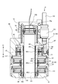
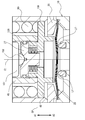
- FIG. 1B is a vertical cross-sectional view of the valve device according to the embodiment of the present invention, taken along the line 1A-1A in FIG. 1B is a top view of the valve device of FIG. 1A.
- FIG. 1D is an enlarged cross-sectional view of the actuator portion taken along the line 1D-1D in FIG. 1B.
- Explanatory drawing which shows operation
- FIG. 6 is a schematic diagram showing an application example of the valve device according to the embodiment of the present invention to a process gas control system of a semiconductor manufacturing apparatus.
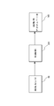
- the functional block diagram which shows schematic structure of a control system.
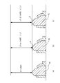
- FIG. 1B is an enlarged cross-sectional view of a main part for explaining a state of the valve device of FIG.
- the flowchart which shows an example of a process of a control part.
- the graph which shows an example of the relationship between the voltage applied to a piezoelectric actuator, and a deviation.
- FIG. 3 is an external perspective view showing an example of a fluid control device.
- FIG. 1A is a cross-sectional view showing the configuration of a valve device 1 according to an embodiment of the present invention, showing a state in which the valve is fully closed.
- 1B is a top view of the valve device 1
- FIG. 1C is an enlarged vertical cross-sectional view of the actuator portion of the valve device 1
- FIG. 1D is an enlarged vertical cross-sectional view of the actuator portion in a direction different by 90 degrees from FIG. 1C
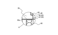
- FIG. It is an expanded sectional view within a circle A.
- A1 in FIG. 1A is upward and A2 is downward.
- the valve device 1 includes a housing box 301 provided on the support plate 302, a valve body 2 installed in the housing box 301, and a pressure regulator 200 installed on the ceiling of the housing box 301.
- 10 is a valve body
- 15 is a valve seat
- 20 is a diaphragm
- 25 is a presser adapter
- 27 is an actuator receiver
- 30 is a bonnet
- 40 is an operating member
- 48 is a diaphragm presser
- 50 is a casing
- 70 is an adjusting body
- 80 is an actuator retainer
- 85 is a position detecting mechanism
- 86 is a magnetic sensor
- 87 is a magnet
- 90 is a coil spring
- 100 is a piezoelectric actuator as an adjusting actuator
- 120 is a disc spring
- 130 Is a partition member
- 150 is a supply pipe
- 160 is a limit switch
- OR is an O-ring as a seal member
- G is compressed
- the valve body 10 is made of a metal such as stainless steel and defines the flow paths 12 and 13.
- the flow path 12 has an opening 12a that opens on one side surface of the valve body 10 at one end, and the pipe joint 501 is connected to the opening 12a by welding.
- the other end 12b of the flow passage 12 is connected to the flow passage 12c extending in the vertical directions A1 and A2 of the valve body 10.
- the upper end of the flow path 12c is opened on the upper surface side of the valve body 10, the upper end is opened on the bottom surface of the recess 11 formed on the upper surface side of the valve body 10, and the lower end is on the lower surface side of the valve body 10. It is open.
- a pressure sensor 400 is provided at the opening on the lower end side of the flow path 12c to close the opening on the lower end side of the flow path 12c.
- a valve seat 15 is provided around the opening at the upper end of the flow path 12c.
- the valve seat 15 is made of a synthetic resin (PFA, PA, PI, PCTFE, etc.), and is fitted and fixed in a mounting groove provided at the upper edge of the opening of the flow path 12c. In this embodiment, the valve seat 15 is fixed in the mounting groove by caulking.
- the flow path 13 has an opening 13a, one end of which opens at the bottom surface of the recess 11 of the valve body 10 and the other end of which opens at the other side surface of the valve body 10 opposite to the flow path 12.
- the pipe joint 502 is connected to 13a by welding.
- the diaphragm 20 is disposed above the valve seat 15, defines a flow path that connects the flow path 12c and the flow path 13, and the central portion of the diaphragm 20 moves up and down to be seated on the valve seat 15. As a result, the flow paths 12 and 13 are opened and closed.
- the diaphragm 20 is made into a spherical shell shape in which the upward convex arc shape is in a natural state by bulging the central portion of a metal thin plate of special stainless steel or the like and a nickel-cobalt alloy thin plate upward. ing.
- the diaphragm 20 is constructed by laminating three thin plates of this special stainless steel and one thin plate of nickel-cobalt alloy.
- the outer peripheral edge of the diaphragm 20 is placed on the protrusion formed on the bottom of the recess 11 of the valve body 10, and the lower end of the bonnet 30 inserted into the recess 11 is screwed into the threaded portion of the valve body 10.
- the valve body 10 is pressed against the protruding portion side via the stainless alloy pressing adapter 25, and is clamped and fixed in an airtight state.
- the nickel-cobalt alloy thin film may have a different structure as the diaphragm arranged on the gas contact side.
- the operation member 40 is a member for operating the diaphragm 20 so that the diaphragm 20 opens and closes the space between the flow passage 12 and the flow passage 13, and is formed in a substantially cylindrical shape, and the upper end side is open.
- the operating member 40 is fitted on the inner peripheral surface of the bonnet 30 via an O-ring OR (see FIGS. 1C and 1D), and is movably supported in the vertical directions A1 and A2.
- a diaphragm retainer 48 having a retainer made of a synthetic resin such as polyimide that contacts the upper surface of the central portion of the diaphragm 20 is attached to the lower end surface of the operation member 40.
- a coil spring 90 is provided between the upper surface of the collar portion 48a formed on the outer peripheral portion of the diaphragm retainer 48 and the ceiling surface of the bonnet 30, and the operating member 40 is constantly moved downward by the coil spring 90 in the downward direction A2. Being energized. Therefore, when the main actuator 60 is not operating, the diaphragm 20 is pressed against the valve seat 15 and the space between the flow passage 12 and the flow passage 13 is closed.
- a disc spring 120 as an elastic member is provided between the lower surface of the actuator receiver 27 and the upper surface of the diaphragm retainer 48.
- the casing 50 is composed of an upper casing member 51 and a lower casing member 52, and a screw on the inner periphery of the lower end portion of the lower casing member 52 is screwed into a screw on the outer periphery of the upper end portion of the bonnet 30. Further, a screw on the outer circumference of the upper end portion of the lower casing member 52 is screwed with a screw on the inner circumference of the lower end portion of the upper casing member 51.
- An annular bulkhead 65 is fixed between the upper end of the lower casing member 52 and the facing surface 51f of the upper casing member 51 facing the upper end.
- An O-ring OR seals between the inner peripheral surface of the bulkhead 65 and the outer peripheral surface of the operating member 40, and between the outer peripheral surface of the bulkhead 65 and the inner peripheral surface of the upper casing member 51.
- the main actuator 60 has annular first to third pistons 61, 62, 63.
- the first to third pistons 61, 62, 63 are fitted on the outer peripheral surface of the operating member 40 and are movable in the vertical direction A1, A2 together with the operating member 40.
- the lower casing member 52 and the inner peripheral surface of the bonnet 30 are sealed with a plurality of O-rings OR. As shown in FIGS.
- a cylindrical partition wall member 130 is fixed to the inner peripheral surface of the operating member 40 so as to have a gap GP1 between the inner peripheral surface of the operating member 40.
- the gap GP1 is sealed by a plurality of O-rings OR1 to OR3 provided between the outer peripheral surfaces on the upper and lower end sides of the partition member 130 and the inner peripheral surface of the operating member 40, and the compressed air G as the driving fluid is sealed. It is a flow passage.
- the flow passage formed by the gap GP1 is arranged concentrically with the piezoelectric actuator 100.
- a gap GP2 is formed between the casing 101 and the partition member 130 of the piezoelectric actuator 100, which will be described later.
- pressure chambers C1 to C3 are formed on the lower surfaces of the first to third pistons 61, 62 and 63, respectively.
- the operation member 40 is formed with flow passages 40h1, 40h2, 40h3 that penetrate in the radial direction at positions communicating with the pressure chambers C1, C2, C3.
- a plurality of flow passages 40h1, 40h2, 40h3 are formed at equal intervals in the circumferential direction of the operating member 40.
- the flow passages 40h1, 40h2, 40h3 are respectively connected to the flow passages formed by the above-mentioned gap GP1.
- the upper casing member 51 of the casing 50 is formed with a flow passage 51h which opens at the upper surface, extends in the vertical directions A1, A2, and communicates with the pressure chamber C1.
- the supply pipe 150 is connected to the opening of the flow passage 51h via a pipe joint 152.
- the compressed air G supplied from the supply pipe 150 is supplied to the pressure chambers C1, C2, C3 through the respective flow passages described above.
- the space SP above the first piston 61 in the casing 50 is connected to the atmosphere through the through hole 70a of the adjustment body 70.
- the limit switch 160 is installed on the casing 50, and the movable pin 161 penetrates the casing 50 and contacts the upper surface of the first piston 61.
- the limit switch 160 detects the amount of movement of the first piston 61 (operation member 40) in the vertical direction A1, A2 in accordance with the movement of the movable pin 161.
- Position Detection Mechanism As shown in FIG. 1E, the position detection mechanism 85 is provided on the bonnet 30 and the operation member 40, and has a magnetic sensor 86 embedded along the radial direction of the bonnet 30 and the magnetic sensor 86.
- the magnet 87 is embedded in a part of the operation member 40 in the circumferential direction so as to face each other.
- the wiring 86a is led out to the outside of the hood 30, the wiring 86a includes a power supply line and a signal line, and the signal line is electrically connected to the control unit 300 described later.
- the magnetic sensor 86 for example, one using a Hall element, one using a coil, one using an AMR element whose resistance value changes depending on the strength and direction of the magnetic field, and the like can be cited. Detection can be non-contact.
- the magnet 87 may be magnetized in the vertical directions A1 and A2, or may be magnetized in the radial direction. Further, the magnet 87 may be formed in a ring shape.
- the magnetic sensor 86 is provided on the bonnet 30 and the magnet 87 is provided on the operation member 40.
- the present invention is not limited to this and can be appropriately changed.
- the piezoelectric actuator 100 has a stacked piezoelectric element (not shown) built in a cylindrical casing 101 shown in FIG.
- the casing 101 is made of a metal such as a stainless alloy, and has a hemispherical end surface on the side of the front end portion 102 and a closed end surface on the side of the base end portion 103.
- the total length of the piezoelectric actuator 100 becomes L0 by applying a predetermined voltage V0 at which the expansion of the piezoelectric actuator 100 becomes d.
- V0 a voltage higher than the predetermined voltage V0
- the total length of the piezoelectric actuator 100 becomes L0+d at maximum
- a voltage (including no voltage) lower than the predetermined voltage V0 the total length of the piezoelectric actuator 100 is minimum L0. -D. Therefore, the entire length from the tip end portion 102 to the base end portion 103 can be expanded and contracted in the vertical directions A1 and A2.
- the tip portion 102 of the piezoelectric actuator 100 has a hemispherical shape, but the present invention is not limited to this, and the tip portion may have a flat surface.
- electric power is supplied to the piezoelectric actuator 100 through the wiring 105.
- the wiring 105 is led to the outside through the through hole 70a of the adjustment body 70.
- the vertical position of the base end portion 103 of the piezoelectric actuator 100 is defined by the lower end surface of the adjustment body 70 via the actuator retainer 80, as shown in FIGS. 1C and 1D.
- the adjustment body 70 has a screw hole formed in the upper portion of the casing 50, and a screw portion provided on the outer peripheral surface of the adjustment body 70 is screwed into the adjustment body 70 to adjust the position of the adjustment body 70 in the vertical direction A1, A2.
- the tip portion 102 of the piezoelectric actuator 100 is in contact with a conical receiving surface formed on the upper surface of the disk-shaped actuator receiver 27 as shown in FIG.
- the actuator receiver 27 is movable in the vertical directions A1 and A2.
- the supply pipe 203 is connected to the primary side via the pipe joint 201, and the pipe joint 151 provided at the tip of the supply pipe 150 is connected to the secondary side.
- the pressure regulator 200 is a well-known poppet valve type pressure regulator, and detailed description thereof will be omitted.
- the high-pressure compressed air G supplied through the supply pipe 203 is lowered to a desired pressure and the pressure on the secondary side is preset.
- the controlled pressure is controlled to be the adjusted pressure. When there is a fluctuation due to pulsation or disturbance in the pressure of the compressed air G supplied through the supply pipe 203, this fluctuation is suppressed and output to the secondary side.
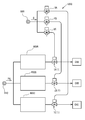
- FIG. 3 shows an example in which the valve device 1 according to the present embodiment is applied to a process gas control system of a semiconductor manufacturing device.
- the semiconductor manufacturing apparatus 1000 of FIG. 3 is, for example, an apparatus for performing a semiconductor manufacturing process by the ALD method
- 800 is a supply source of compressed air G
- 810 is a supply source of process gas PG
- 900A to 900C are fluid control.
- Devices, VA to VC are opening/closing valves
- 1A to 1C are valve devices according to the present embodiment
- CHA to CHC are processing chambers.
- the fluid control devices 900A to 900C are integrated gas systems in which various fluid devices such as open/close valves, regulators, and mass flow controllers are integrated in order to supply accurately measured process gases PG to the processing chambers CHA to CHC, respectively. is there.
- the valve devices 1A to 1C precisely control the flow rates of the process gas PG from the fluid control devices 900A to 900C by opening and closing the diaphragm 20 and supply the process gases PG to the processing chambers CHA to CHC, respectively.
- the opening/closing valves VA to VC execute the cutoff of the supply of the compressed air G according to the control command in order to open/close the valve devices 1A to 1C.
- compressed air is supplied from the common supply source 800, but the open/close valves VA to VC are driven independently.
- the compressed air G having a substantially constant pressure is constantly output from the common supply source 800.
- the open/close valves VA to VC are independently opened/closed, they are affected by pressure loss when the valves are opened/closed.
- the pressure of the compressed air G supplied to each of the devices 1A to 1C fluctuates and is not constant. If the pressure of the compressed air G supplied to the valve devices 1A to 1C fluctuates, the flow rate adjustment amount by the piezoelectric actuator 100 may fluctuate.
- the pressure regulator 200 described above is provided.
- the control unit 300 receives the detection signal of the magnetic sensor 86 and drives and controls the piezoelectric actuator 100.
- the control unit 300 includes, for example, hardware such as a processor and a memory and required software (not shown) and a driver that drives the piezoelectric actuator 100. A specific example of the control of the piezoelectric actuator 100 by the control unit 300 will be described later.
- FIGS. 5 and 6 show the valve device 1 in the fully open state
- FIG. 6 shows the valve device 1 in the fully closed state.
- the compressed air G is not supplied.
- the disc spring 120 has already been compressed to some extent and elastically deformed, and the restoring force of the disc spring 120 constantly urges the actuator receiver 27 in the upward direction A1.
- the piezoelectric actuator 100 is always biased in the upward direction A1, and the upper surface of the base end portion 103 is pressed against the actuator retainer 80.
- the piezoelectric actuator 100 receives a compressive force in the vertical directions A1 and A2 and is arranged at a predetermined position with respect to the valve body 10. Since the piezoelectric actuator 100 is not connected to any member, it can move relative to the operating member 40 in the vertical directions A1 and A2.
- the number and direction of the disc springs 120 can be changed appropriately according to the conditions. Further, other elastic members such as a coil spring and a leaf spring can be used in addition to the disc spring 120, but the use of the disc spring has an advantage that the spring rigidity, stroke and the like can be easily adjusted.
- a gap is formed between the contact surface 48t.
- the positions of the restriction surface 27b in the vertical direction A1 and A2 are the open positions OP in the state where the opening degree is not adjusted.
- the distance between the regulation surface 27b and the contact surface 48t in the fully closed state corresponds to the lift amount Lf of the diaphragm 20 shown in FIG.
- the lift amount Lf defines the opening degree of the valve, that is, the flow rate.
- the lift amount Lf can be changed by adjusting the positions of the adjustment body 70 in the vertical directions A1 and A2.
- the diaphragm retainer 48 (operation member 40) in the state shown in FIG. 5 is located at the closed position CP with reference to the contact surface 48t.
- the contact surface 48t moves to a position where it contacts the restriction surface 27b of the actuator receiver 27, that is, to the open position OP, the diaphragm 20 is separated from the valve seat 15 by the lift amount Lf.
- the compressed air G When the compressed air G is supplied into the valve device 1 through the supply pipe 150, a thrust force that pushes up the operating member 40 in the upward direction A1 is generated in the main actuator 60.
- the pressure of the compressed air G is set to a value sufficient to move the operating member 40 in the upward direction A1 against the downward A2 biasing force acting on the operating member 40 from the coil spring 90 and the disc spring 120. There is.
- the operating member 40 moves in the upward direction A1 while further compressing the disc spring 120, and the contact surface 48t of the diaphragm retainer 48 comes into contact with the restriction surface 27b of the actuator receiver 27.
- the actuator receiver 27 receives a force from the operation member 40 in the upward direction A1.
- This force acts as a force that compresses the piezoelectric actuator 100 in the vertical directions A1 and A2 through the tip portion 102 of the piezoelectric actuator 100. Therefore, the upward force A1 acting on the operating member 40 is received by the tip portion 102 of the piezoelectric actuator 100, and the movement of the operating member 40 in the A1 direction is restricted at the open position OP. In this state, the diaphragm 20 is separated from the valve seat 15 by the lift amount Lf described above.
- the position detection mechanism 85 detects the relative displacement between the valve body 10 and the magnetic sensor 86 in the state shown in FIGS. 5 and 6.
- the valve opening VOP is calculated as shown in FIG. 9 by using sampling data obtained by sampling the signal detected by the position detection mechanism 85 at a predetermined sampling time (step S1).
- the valve opening degree VOP is defined by the difference between the displacement P converted from the detection output of the position detection mechanism 85 and the origin position P0, and basically, the magnetic sensor 86 at the position where the diaphragm 20 is in contact with the valve seat 15.
- the origin position P0 is determined from the detection output of the magnetic sensor 86 when the diaphragm 20 is in contact with the valve seat 15, and the initial origin position P0 is set on the valve seat 15 in the condition shown in FIG. 7A. Is in contact with. However, even when the diaphragm 20 is in contact with the valve seat 15, since the valve seat 15 is made of resin, it may be deformed as shown in FIG. 7B or FIG. , The output of the magnetic sensor 86 is not constant. Therefore, as described later, it is necessary to determine the origin position P0 from the output of the magnetic sensor 86 that has sampled. The initial origin position P0 can be determined when the product is shipped. In addition, a temperature sensor may be separately provided to correct the temperature of the value of the displacement P and the value of the origin position P0.
- the deviation e between the valve opening VOP and the lift amount Lf is calculated (step S2).
- a deviation occurs between the valve opening degree VOP and the lift amount Lf in the open state.
- the deviation e is ⁇
- the deviation e is ⁇ .
- step S3: Y a voltage according to the magnitude of the deviation e is applied to the piezoelectric actuator 100. That is, feedback control is performed. Although the deviation e is compensated only by the gain element Kp in the present embodiment, it may be compensated by PID.
- step S3: N 0 [V] is applied to the piezoelectric actuator 100. As shown in FIG.
- step S4 the voltage is applied to the piezoelectric actuator 100 only when the deviation e is ⁇ eth or more (step S4), and 0 [V] is applied otherwise (step S5).
- step S5 the piezoelectric actuator 100 does not operate (does not expand), so the life of the piezoelectric actuator 100 can be extended accordingly.
- the displacement P is close to the value of the origin position P0, and the value of the valve opening degree VOP, which is the calculation result of step S1, becomes extremely small.
- the lift amount Lf is subtracted from the valve opening degree VOP in the valve closed state in step S2
- the deviation e always becomes a negative value.
- the deviation e When the deviation e is negative, it means that the valve opening degree VOP is smaller than the lift amount Lf, and when step S4 is performed in this state, the voltage applied to the piezoelectric actuator 100 is always a negative value. As a result, the voltage applied to the piezoelectric actuator 100 has a negative value and is substantially 0 [V]. Therefore, it is not necessary to determine that the valve opening degree VOP has fallen below the predetermined opening degree, and therefore the above-mentioned steps S3 and 5 can be omitted. Can be expected.
- the origin position determination control unit 300 determines from the output of the magnetic sensor 86 whether the valve is closed (step S6). When it is determined that the valve is closed, the origin position is detected (step S7).
- the control unit 300 also serves as the origin position determining unit (step S6:Y).
- the detection of the origin position is performed by the following method, for example. (1) The output value of the magnetic sensor is sampled, and the sensor output value at the time point traced back by a predetermined time T0 from the time point when the valve closed state changes to the valve open state (time point when the sensor output value exceeds the threshold value) is set as the origin position.
- Adopt and update step S8.
- the left side of the center line Ct in FIGS. 8A and 8B shows the state shown in FIG. 5, and the right side of the center line Ct shows the state after adjusting the position of the operation member 40 in the vertical direction A1, A2. Showing.
- the piezoelectric actuator 100 is extended to move the operating member 40 in the downward direction A2.
- the lift amount Lf- after adjustment which is the distance between the diaphragm 20 and the valve seat 15, becomes smaller than the lift amount Lf before adjustment.
- the extension amount of the piezoelectric actuator 100 may be the deformation amount of the valve seat 15 detected by the position detection mechanism 85.
- the piezoelectric actuator 100 When adjusting in the direction of increasing the flow rate of the fluid, as shown in FIG. 8B, the piezoelectric actuator 100 is shortened to move the operating member 40 in the upward direction A1. As a result, the lift amount Lf+ after adjustment, which is the distance between the diaphragm 20 and the valve seat 15, becomes larger than the lift amount Lf before adjustment.
- the reduction amount of the piezoelectric actuator 100 may be the deformation amount of the valve seat 15 detected by the position detection mechanism 85.
- the maximum value of the lift amount Lf of the diaphragm 20 is about 100 to 200 ⁇ m, and the adjustment amount by the piezoelectric actuator 100 is about ⁇ 20 ⁇ m. That is, the stroke of the piezoelectric actuator 100 cannot cover the lift amount of the diaphragm 20, but by using the main actuator 60 operating with the compressed air G and the piezoelectric actuator 100 together, the main actuator 60 having a relatively long stroke. Since the flow rate can be precisely adjusted by the piezoelectric actuator 100 having a relatively short stroke while ensuring the flow rate supplied by the valve device 1, there is no need to manually adjust the flow rate by the adjustment body 70 or the like. Man-hours are significantly reduced. According to the present embodiment, the flow rate can be precisely adjusted by simply changing the voltage applied to the piezoelectric actuator 100. Therefore, the flow rate can be immediately adjusted and the flow rate can be controlled in real time.
- the piezoelectric actuator 100 is used as the adjustment actuator that uses the passive element that expands and contracts according to a given input signal, but the present invention is not limited to this.
- an electrically driven material made of a compound that deforms in response to a change in electric field can be used as the actuator. It is possible to change the shape and size of the electrically driven material by an electric current or a voltage to change the defined open position of the operating member 40.
- Such an electrically driven material may be a piezoelectric material or an electrically driven material other than the piezoelectric material.
- an electrically driven polymer material can be used.
- the electrically driven polymer material is also called an electro active polymer (EAP).
- EAP electro active polymer
- an electric EAP driven by an external electric field or Coulomb force and a solvent swelling the polymer are caused to flow by the electric field.
- nonionic EAP to be deformed ionic EAP driven by movement of ions or molecules by an electric field, and the like, and any one or a combination thereof can be used.
- a so-called normally closed type valve is taken as an example, but the present invention is not limited to this, and can be applied to a normally open type valve.
- valve device 1 is used in the semiconductor manufacturing process by the ALD method
- present invention is not limited to this, and the present invention is, for example, an atomic layer etching method (ALE: Atomic Layer Etching method) or the like. It can be applied to any object that requires precise flow rate adjustment.
- ALE Atomic Layer Etching method
- the piston contained in the cylinder chamber operated by gas pressure is used as the main actuator, but the present invention is not limited to this, and various optimum actuators can be selected according to the control target. Is.
- the position detection mechanism includes a magnetic sensor and a magnet, but the position detection mechanism is not limited to this, and a non-contact position sensor such as an optical position detection sensor can be adopted.
- FIG. 11 An example of a fluid control device to which the valve device of the present invention is applied will be described with reference to FIG. 11.
- the fluid control device shown in FIG. 11 is provided with a metal base plate BS which is arranged along the width directions W1 and W2 and extends in the longitudinal directions G1 and G2.
- W1 indicates the front side
- W2 indicates the rear side
- G1 indicates the upstream side
- G2 indicates the downstream direction.
- Various fluid devices 991A to 991E are installed on the base plate BS via a plurality of flow path blocks 992, and the plurality of flow path blocks 992 allow a fluid to flow from the upstream side G1 toward the downstream side G2 (not shown). Are formed respectively.
- the "fluid device” is a device used in a fluid control device that controls the flow of fluid, and includes a body that defines a fluid flow path, and at least two flow path ports that open at the surface of this body. Is a device having. Specifically, it includes an on-off valve (two-way valve) 991A, a regulator 991B, a pressure gauge 991C, an on-off valve (three-way valve) 991D, a mass flow controller 991E, and the like, but is not limited thereto.
- the introduction pipe 993 is connected to a flow path port on the upstream side of the above-mentioned flow path (not shown).
- the present invention can be applied to various valve devices such as the on-off valves 991A and 991D and the regulator 991B described above.
- Valve device 2 Valve body 10: Valve body 11: Recess 12: Flow path 12a: Opening 12b: Other end 12c, 13: Flow path 15: Valve seat 20: Diaphragm 25: Presser adapter 27: Actuator receiver 27b: Control surface 30: Bonnet 40: Operating members 40h1-40h3: Flow passage 48: Diaphragm retainer 48a: Collar portion 48t: Contact surface 50: Casing 51: Upper casing member 51f: Opposing surface 51h: Flow passage 52: Lower casing member 60: Main actuator 61: First piston 62: Second piston 63: Third piston 65: Bulkhead 70: Adjustment body 70a: Through hole 80: Actuator retainer 85: Position detection mechanism 86 : Magnetic sensor 86a: Wiring 87: Magnet 90: Coil spring 100: Piezoelectric actuator (adjustment actuator) 101: Casing 102: Tip part 103: Base part 105: Wiring 120: Disc spring 130: Part
Landscapes
- Engineering & Computer Science (AREA)
- General Engineering & Computer Science (AREA)
- Mechanical Engineering (AREA)
- Physics & Mathematics (AREA)
- Fluid Mechanics (AREA)
- General Physics & Mathematics (AREA)
- Automation & Control Theory (AREA)
- Flow Control (AREA)
- Fluid-Driven Valves (AREA)
- Indication Of The Valve Opening Or Closing Status (AREA)
- Lift Valve (AREA)
- Electrically Driven Valve-Operating Means (AREA)
Abstract
Description
通常、上記の流体制御装置から出力される処理ガスを処理チャンバに直接供給するが、原子層堆積法(ALD:Atomic Layer Deposition 法)により基板に膜を堆積させる処理プロセスにおいては、処理ガスを安定的に供給するために流体制御装置から供給される処理ガスをバッファとしてのタンクに一時的に貯留し、処理チャンバの直近に設けられたバルブを高頻度で開閉させてタンクからの処理ガスを真空雰囲気の処理チャンバへ供給することが行われている。なお、処理チャンバの直近に設けられるバルブとしては、例えば、特許文献1を参照。
ALD法は、化学気相成長法の1つであり、温度や時間等の成膜条件の下で、2種類以上の処理ガスを1種類ずつ基板表面上に交互に流し、基板表面上原子と反応させて単層ずつ膜を堆積させる方法であり、単原子層ずつ制御が可能である為、均一な膜厚を形成させることができ、膜質としても非常に緻密に膜を成長させることができる。
ALD法による半導体製造プロセスでは、処理ガスの流量を精密に調整する必要がある。
このため、処理ガスの流量をより精密にコントロールするには、流量の経時変化に応じて流量調整の必要がある。
本出願人は、供給される駆動流体の圧力を受けて作動する主アクチュエータに加えて、ダイヤフラムを操作する操作部材の位置を調整するための調整用アクチュエータを設け、自動で流量を精密に調整可能なバルブ装置を特許文献2において提案している。
従来においては、特許文献2に開示されたバルブ装置に対しては、弁体としてのダイヤフラムの開度を検出して、さらに精密な流量制御に対する要請があった。
本発明の他の目的は、上記のバルブ装置を用いた流量制御方法、流体制御装置、半導体製造方法および半導体製造装置を提供することにある。
前記バルブボディの前記開口部の周囲に設けられたバルブシート
前記開口部を覆いつつ流路と外部とを隔て、かつ、前記バルブシートに当接および離隔することで流路を開閉する弁体としてのダイヤフラムと、
前記ダイヤフラムに流路を閉鎖させる閉位置と前記ダイヤフラムに流路を開放させる開位置との間で移動可能に設けられた前記ダイヤフラムを操作する操作部材と、
供給される駆動流体の圧力を受けて、前記操作部材を前記開位置又は閉位置に移動させる主アクチュエータと、
与えられた入力信号に応じて伸縮する受動要素を利用し、かつ、前記開位置に位置付けられた前記操作部材の位置を調整するための調整用アクチュエータと、
前記バルブボディに対する前記操作部材の位置を検出するための位置検出機構と、
前記ダイヤフラムが前記バルブシートに当接する弁閉状態を利用して前記位置検出機構の原点位置を決定する原点位置決定部と、を有する。
前記複数の流体機器は、上記構成のバルブ装置を含む。
バルブ装置1は、支持プレート302上に設けられた収容ボックス301と、収容ボックス301内に設置されたバルブ本体2と、収容ボックス301の天井部に設置された圧力レギュレータ200とを有する。
図1A~図1Eにおいて、10はバルブボディ、15はバルブシート、20はダイヤフラム、25は押えアダプタ、27はアクチュエータ受け、30はボンネット、40は操作部材、48はダイヤフラム押え、50はケーシング、60は主アクチュエータ、70は調整ボディ、80はアクチュエータ押え、85は位置検出機構、86は磁気センサ、87は磁石、90はコイルばね、100は調整用アクチュエータとしての圧電アクチュエータ、120は皿ばね、130は隔壁部材、150は供給管、160はリミットスイッチ、ORはシール部材としてのOリング、Gは駆動流体としての圧縮エアを示す。なお、駆動流体は、圧縮エアに限定されるわけではなく他の流体を用いることも可能である。
流路12cの上端部の開口の周囲にバルブシート15が設けられている。バルブシート15は、合成樹脂(PFA、PA、PI、PCTFE等)製であり、流路12cの上端側の開口周縁に設けられた装着溝に嵌合固定されている。なお、本実施形態では、かしめ加工によりバルブシート15が装着溝内に固定されている。
流路13は、一端がバルブボディ10の凹部11の底面で開口し、かつ、他端にバルブボディ10の流路12とは反対側の他側面で開口する開口部13aを有し、開口部13aに管継手502が溶接により接続されている。
ダイヤフラム20は、その外周縁部がバルブボディ10の凹部11の底部に形成された突出部上に載置され、凹部11内へ挿入したボンネット30の下端部をバルブボディ10のねじ部へねじ込むことにより、ステンレス合金製の押えアダプタ25を介してバルブボディ10の前記突出部側へ押圧され、気密状態で挾持固定されている。尚、ニッケル・コバルト合金薄膜は、接ガス側に配置されているダイヤフラムとしては、他の構成のものも使用可能である。
操作部材40の下端面にはダイヤフラム20の中央部上面に当接するポリイミド等の合成樹脂製の押え部を有したダイヤフラム押え48が装着されている。
ダイヤフラム押え48の外周部に形成された鍔部48aの上面と、ボンネット30の天井面との間には、コイルばね90が設けられ、操作部材40はコイルばね90により下方向A2に向けて常時付勢されている。このため、主アクチュエータ60が作動していない状態では、ダイヤフラム20はバルブシート15に押し付けられ、流路12と流路13の間は閉じられた状態となる。
ケーシング50は、上側ケーシング部材51と下側ケーシング部材52からなり、下側ケーシング部材52の下端部内周のねじがボンネット30の上端部外周のねじに螺合している。また、下側ケーシング部材52の上端部外周のねじに上側ケーシング部材51の下端部内周のねじが螺合している。
下側ケーシング部材52の上端部とこれに対向する上側ケーシング部材51の対向面51fとの間には、環状のバルクヘッド65が固定されている。バルクヘッド65の内周面と操作部材40の外周面との間およびバルクヘッド65の外周面と上側ケーシング部材51の内周面との間は、OリングORによりそれぞれシールされている。
図1Cおよび1Dに示すように、操作部材40の内周面には、円筒状の隔壁部材130が当該操作部材40の内周面との間に間隙GP1を持つように固定されている。間隙GP1は、隔壁部材130の上端側および下端側の外周面と操作部材40の内周面との間に設けられた複数のOリングOR1~OR3によりシールされ、駆動流体としての圧縮エアGの流通路となっている。この間隙GP1で形成される流通路は、圧電アクチュエータ100と同心状に配置されている。後述する圧電アクチュエータ100のケーシング101と隔壁部材130との間には、間隙GP2が形成されている。
操作部材40には、圧力室C1,C2,C3に連通する位置において半径方向に貫通する流通路40h1,40h2,40h3が形成されている。流通路40h1,40h2,40h3は、操作部材40の周方向に等間隔に複数形成されている。流通路40h1,40h2,40h3は、上記した間隙GP1で形成される流通路とそれぞれ接続されている。
ケーシング50の上側ケーシング部材51には、上面で開口し上下方向A1,A2に延びかつ圧力室C1に連通する流通路51hが形成されている。流通路51hの開口部には、管継手152を介して供給管150が接続されている。これにより、供給管150から供給される圧縮エアGは、上記した各流通路を通じて圧力室C1,C2,C3に供給される。
ケーシング50内の第1のピストン61の上方の空間SPは、調整ボディ70の貫通孔70aを通じて大気につながっている。
位置検出機構
図1Eに示すように、位置検出機構85は、ボンネット30と操作部材40とに設けられており、ボンネット30の半径方向に沿って埋め込まれた磁気センサ86と、この磁気センサ86に対向するように操作部材40の周方向の一部に埋め込まれた磁石87とを含む。
磁気センサ86は、配線86aがボンネット30の外部に導出されており、配線86aは給電線と信号線からなり、信号線は後述する制御部300に電気的に接続される。磁気センサ86としては、例えば、ホール素子を利用したもの、コイルを利用したもの、磁界の強さや向きによって抵抗値が変化するAMR素子を利用したもの等が挙げられ、磁石との組み合わせにより、位置検知を非接触にできる。
磁石87は、上下方向A1,A2に着磁されていてもよいし、半径方向に着磁されていてもよい。また、磁石87はリング状に形成されていてもよい。
なお、本実施形態では、磁気センサ86をボンネット30に設け、磁石87を操作部材40に設けたが、これに限定されるわけではなく、適宜変更できる。例えば、押えアダプタ25に磁気センサ86を設け、ダイヤフラム押え48の外周部に形成された鍔部48aの対向する位置に磁石87を設けることも可能である。バルブボディ10に対して移動する側に磁石87を設置し、バルブボディ10又はバルブボディ10に対して移動しない側に磁気センサ86を設置することが好ましい。
圧電アクチュエータ100は、図2に示す円筒状のケーシング101に図示しない積層された圧電素子を内蔵している。ケーシング101は、ステンレス合金等の金属製で、半球状の先端部102側の端面および基端部103側の端面が閉塞している。積層された圧電素子に入力信号としての電圧を印加して伸長させることで、ケーシング101の先端部102側の端面が弾性変形し、半球状の先端部102が長手方向において変位する。積層された圧電素子の最大ストロークを2dとすると、圧電アクチュエータ100の伸びがdとなる所定電圧V0を予めかけておくことで、圧電アクチュエータ100の全長はL0となる。そして、所定電圧V0よりも高い電圧をかけると、圧電アクチュエータ100の全長は最大でL0+dとなり、所定電圧V0よりも低い電圧(無電圧を含む)をかけると、圧電アクチュエータ100の全長は最小でL0-dとなる。したがって、上下方向A1,A2において先端部102から基端部103までの全長を伸縮させることができる。なお、本実施形態では、圧電アクチュエータ100の先端部102を半球状としたが、これに限定されるわけではなく、先端部が平坦面であってもよい。
図1Aや図1Cに示すように、圧電アクチュエータ100への給電は、配線105により行われる。配線105は、調整ボディ70の貫通孔70aを通じて外部に導出されている。
圧電アクチュエータ100の先端部102は、図1に示すように円盤状のアクチュエータ受け27の上面に形成された円錐面状の受け面に当接している。アクチュエータ受け27は、上下方向A1,A2に移動可能となっている。
圧力レギュレータ200は、周知のポペットバルブ式の圧力レギュレータであり、詳細説明を省略するが、供給管203を通じて供給される高圧の圧縮エアGを所望の圧力へ下げて二次側の圧力が予め設定された調節された圧力になるように制御される。供給管203を通じて供給される圧縮エアGの圧力に脈動や外乱による変動が存在する場合に、この変動を抑制して二次側へ出力する。
図3の半導体製造装置1000は、例えば、ALD法による半導体製造プロセスを実行するための装置であり、800は圧縮エアGの供給源、810はプロセスガスPGの供給源、900A~900Cは流体制御装置、VA~VCは開閉バルブ、1A~1Cは本実施形態に係るバルブ装置、CHA~CHCは処理チャンバである。
ALD法による半導体製造プロセスでは、プロセスガスの流量を精密に調整する必要があるとともに、基板の大口径化により、処理ガスの流量を確保する必要もある。
流体制御装置900A~900Cは、正確に計量したプロセスガスPGを処理チャンバCHA~CHCにそれぞれ供給するために、開閉バルブ、レギュレータ、マスフローコントローラ等の各種の流体機器を集積化した集積化ガスシステムである。
バルブ装置1A~1Cは、上記したダイヤフラム20の開閉により、流体制御装置900A~900CからのプロセスガスPGの流量を精密に制御して処理チャンバCHA~CHCにそれぞれ供給する。
開閉バルブVA~VCは、バルブ装置1A~1Cに開閉動作させるために、制御指令に応じて圧縮エアGの供給遮断を実行する。
共通の供給源800からは、ほぼ一定の圧力の圧縮エアGが常時出力されるが、開閉バルブVA~VCがそれぞれ独立に開閉されると、バルブ開閉時の圧力損失等の影響を受けてバルブ装置1A~1Cにそれぞれ供給される圧縮エアGの圧力が変動を起こし、一定ではなくなる。
バルブ装置1A~1Cに供給される圧縮エアGの圧力が変動すると、上記した圧電アクチュエータ100による流量調整量が変動してしまう可能性がある。この問題を解決するために、上記した圧力レギュレータ200が設けられている。
図4に示すように、制御部300は、磁気センサ86の検出信号が入力され、圧電アクチュエータ100を駆動制御するようになっている。制御部300は、例えば、図示しない、プロセッサ、メモリ等のハードウエアおよび所要のソフトウエアと圧電アクチュエータ100を駆動するドライバとを含む。制御部300による圧電アクチュエータ100の制御の具体例については後述する。
図5はバルブ装置1のバルブ全開状態を示し、図6はバルブ装置1のバルブ全閉状態を示している。図6に示す状態では、圧縮エアGは供給されていない。この状態において、皿ばね120は既にある程度圧縮されて弾性変形しており、この皿ばね120の復元力により、アクチュエータ受け27は上方向A1に向けて常時付勢されている。これにより、圧電アクチュエータ100も上方向A1に向けて常時付勢され、基端部103の上面がアクチュエータ押え80に押し付けられた状態となっている。これにより、圧電アクチュエータ100は、上下方向A1,A2の圧縮力を受け、バルブボディ10に対して所定の位置に配置される。圧電アクチュエータ100は、いずれの部材にも連結されていないので、操作部材40に対して上下方向A1,A2において相対的に移動可能である。
皿ばね120の個数や向きは条件に応じて適宜変更できる。また、皿ばね120以外にもコイルばね、板ばね等の他の弾性部材を使用できるが、皿ばねを使用すると、ばね剛性やストローク等を調整しやすいという利点がある。
先ず、上記した位置検出機構85は、図5および図6に示す状態におけるバルブボディ10と磁気センサ86との相対変位を検出している。位置検出機構85の検出する信号を所定のサンプリング時間でサンプリングしたサンプリングデータを用いて、図9に示すように、バルブ開度VOPを算出する(ステップS1)。バルブ開度VOPは、位置検出機構85の検出出力から換算された変位Pと原点位置P0の差で定義され、基本的には、バルブシート15にダイヤフラム20が接触した位置での磁気センサ86の出力と、ダイヤフラム20がバルブシート15から離れた状態の磁気センサ86との差を変位量に換算することで求めることができる。
原点位置P0は、ダイヤフラム20がバルブシート15に接触した状態の磁気センサ86の検出出力から決定され、初期の原点位置P0は、図7の(a)に示した状態のバルブシート15にダイヤフラム20が当接した状態である。しかし、バルブシート15にダイヤフラム20が当接した状態であっても、バルブシート15が樹脂であるため図7の(b)や図7の(c)のように変形することや外乱の影響で、磁気センサ86の出力が一定にはならない。このため、後述するように、原点位置P0をサンプリングした磁気センサ86の出力から決定する必要がある。なお、初期の原点位置P0は製品出荷時に決定することができる。また、別途温度センサを設けて、変位Pの値、および原点位置P0の値に温度補正を行っても良い。
次いで、偏差eが所定の閾値-eth(ethは正の値)よりも小さいかを判断する(ステップS3)。これは、バルブ装置1がバルブ閉状態にある場合には開度調整が不要であるため、開度調整が不要かどうかを判断する。すなわち、バルブ開度VOPが所定開度を下回ったかを判断する。
バルブ開度VOPが所定開度よりも大きいと判断される場合(ステップS3:Y)には、圧電アクチュエータ100に偏差eの大きさに応じた電圧が印加される。すなわち、フィードバック制御が行われる。なお、本実施形態では、偏差eをゲイン要素Kpのみで補償したが、PID補償してもよい。
バルブ開度VOPが所定開度を下回ったと判断される場合(ステップS3:N)には、圧電アクチュエータ100に0[V]が印加される。
図10に示すように、偏差eが-eth以上の場合にのみ圧電アクチュエータ100に電圧が印加され(ステップS4)、それ以外は0[V]が印加される(ステップS5)。これにより、バルブの開度調整が不要の場合には、圧電アクチュエータ100は作動しない(伸長しない)ので、その分、圧電アクチュエータ100の寿命を延ばすことができる。
なお、バルブ閉状態では、変位Pは原点位置P0の値の近傍となり、ステップS1の算出結果であるバルブ開度VOPの値は極端に小さくなる。次いで、ステップS2で当該バルブ閉状態でのバルブ開度VOPからリフト量Lfを減算すると、偏差eは必ず負の値になる。偏差eが負の場合はリフト量Lfよりバルブ開度VOPが少ないことを意味し、この状態でステップS4が行われると、圧電アクチュエータ100への印加電圧は必ず負の値になる。この結果、圧電アクチュエータ100への印加電圧は負の値となり、実質的に0[V]となる。従って、バルブ開度VOPが所定開度を下回ったと判断する必要がないため、上述のステップS3、ステップ5は省略が可能であり、省略した場合、ステップ数の減少によって、処理速度の高速化が期待できる。
制御部300では、磁気センサ86の出力からバルブ閉状態かを判断する(ステップS6)。バルブ閉状態にあると判断される場合には、原点位置を検出する(ステップS7)。制御部300は原点位置決定部を兼ねている(ステップS6:Y)。
原点位置の検出は、例えば、以下のような方法により行われる。
(1)磁気センサの出力値をサンプルし、弁閉状態から弁開状態になった時点(センサ出力値が閾値を超えた時点)から所定時間T0だけさかのぼった時点のセンサ出力値を原点位置として採用し更新する(ステップS8)。
(2)磁気センサの出力値をサンプルし、弁閉状態から弁開状態になる時点まで(センサ出力値が閾値を超える時点まで)、センサ出力値の移動平均をt時間毎に算出し、原点位置として更新する。
(3)磁気センサの出力値をサンプルし、弁閉状態から弁開状態になる時点(センサ出力値が閾値を超えた時点)までのセンサ出力値の中で最も低い出力値を原点位置として採用し更新する。
流体の流量を減少させる方向に調整する場合には、図8Aに示すように、圧電アクチュエータ100を伸長させて、操作部材40を下方向A2に移動させる。これにより、ダイヤフラム20とバルブシート15との距離である調整後のリフト量Lf-は、調整前のリフト量Lfよりも小さくなる。圧電アクチュエータ100の伸長量は位置検出機構85で検出したバルブシート15の変形量としてもよい。
流体の流量を増加させる方向に調整する場合には、図8Bに示すように、圧電アクチュエータ100を短縮させて、操作部材40を上方向A1に移動させる。これにより、ダイヤフラム20とバルブシート15との距離である調整後のリフト量Lf+は、調整前のリフト量Lfよりも大きくなる。圧電アクチュエータ100の縮小量は位置検出機構85で検出したバルブシート15の変形量としてもよい。
すなわち、圧電アクチュエータ100のストロークでは、ダイヤフラム20のリフト量をカバーすることができないが、圧縮エアGで動作する主アクチュエータ60と圧電アクチュエータ100を併用することで、相対的にストロークの長い主アクチュエータ60でバルブ装置1の供給する流量を確保しつつ、相対的にストロークの短い圧電アクチュエータ100で精密に流量調整することができ、調整ボディ70等により手動で流量調整をする必要がなくなるので、流量調整工数が大幅に削減される。
本実施形態によれば、圧電アクチュエータ100に印加する電圧を変化させるだけで精密な流量調整が可能であるので、流量調整を即座に実行できるとともに、リアルタイムに流量制御をすることも可能となる。
電気駆動型高分子材料は、電気活性高分子材料(Electro Active Polymer:EAP)ともよばれ、例えば外部電場やクーロン力により駆動する電気性EAP、およびポリマーを膨潤させている溶媒を電場により流動させて変形させる非イオン性EAP、電場によるイオンや分子の移動により駆動するイオン性EAP等があり、これらのいずれか又は組合せを用いることができる。
図11に示す流体制御装置には、幅方向W1,W2に沿って配列され長手方向G1,G2に延びる金属製のベースプレートBSが設けられている。なお、W1は正面側、W2は背面側,G1は上流側、G2は下流側の方向を示している。ベースプレートBSには、複数の流路ブロック992を介して各種流体機器991A~991Eが設置され、複数の流路ブロック992によって、上流側G1から下流側G2に向かって流体が流通する図示しない流路がそれぞれ形成されている。
2 :バルブ本体
10 :バルブボディ
11 :凹部
12 :流路
12a :開口部
12b :他端
12c,13 :流路
15 :バルブシート
20 :ダイヤフラム
25 :押えアダプタ
27 :アクチュエータ受け
27b :規制面
30 :ボンネット
40 :操作部材
40h1-40h3 :流通路
48 :ダイヤフラム押え
48a :鍔部
48t :当接面
50 :ケーシング
51 :上側ケーシング部材
51f :対向面
51h :流通路
52 :下側ケーシング部材
60 :主アクチュエータ
61 :第1のピストン
62 :第2のピストン
63 :第3のピストン
65 :バルクヘッド
70 :調整ボディ
70a :貫通孔
80 :アクチュエータ押え
85 :位置検出機構
86 :磁気センサ
86a :配線
87 :磁石
90 :コイルばね
100 :圧電アクチュエータ(調整用アクチュエータ)
101 :ケーシング
102 :先端部
103 :基端部
105 :配線
120 :皿ばね
130 :隔壁部材
150 :供給管
151,152 :管継手
160 :リミットスイッチ
161 :可動ピン
200 :圧力レギュレータ
201 :管継手
203 :供給管
300 :制御部
301 :収容ボックス
302 :支持プレート
400 :圧力センサ
501,502 :管継手
800,810:供給源
900A-900C :流体制御装置
1000 :半導体製造装置
A :円
A1 :上方向
A2 :下方向
C1-C3 :圧力室
CHA,CHB,CHC:処理チャンバ
CP :閉位置
Ct :中心線
G :圧縮エア(駆動流体)
GP1,GP2:間隙
Lf :リフト量
OP :開位置
OR-OR3 :Oリング
PG :プロセスガス
P :変位
P0 :原点位置
SP :空間
V0 :所定電圧
VA-VC :開閉バルブ
VOP :開位置
991A-991E :流体機器
992 :流路ブロック
993 :導入管
Claims (9)
- 流体が流通する流路と、当該流路の途中で外部に開口する開口部とを画定するバルブボディと、
前記バルブボディの前記開口部の周囲に設けられたバルブシート
前記開口部を覆いつつ流路と外部とを隔て、かつ、前記バルブシートに当接および離隔することで流路を開閉する弁体としてのダイヤフラムと、
前記ダイヤフラムに流路を閉鎖させる閉位置と前記ダイヤフラムに流路を開放させる開位置との間で移動可能に設けられた前記ダイヤフラムを操作する操作部材と、
供給される駆動流体の圧力を受けて、前記操作部材を前記開位置又は閉位置に移動させる主アクチュエータと、
与えられた入力信号に応じて伸縮する受動要素を利用し、かつ、前記開位置に位置付けられた前記操作部材の位置を調整するための調整用アクチュエータと、
前記バルブボディに対する前記操作部材の位置を検出するための位置検出機構と、
前記ダイヤフラムが前記バルブシートに当接する弁閉状態を利用して前記位置検出機構の原点位置を決定する原点位置決定部と、を有するバルブ装置。 - 前記原点位置決定部は、弁閉毎に原点位置を決定し、更新する、請求項1に記載のバルブ装置。
- 前記原点位置決定部は、前記位置検出機構の検出信号をサンプリングし、弁閉状態から弁開状態に移行する際のサンプリングデータに基づいて、原点位置を決定する、請求項1又は2に記載のバルブ装置。
- 弁開度が目標開度になるように、前記調整用アクチュエータを駆動して前記原点決定部の決定した原点位置から前記操作部材を目標位置に制御する制御部をさらに有する、請求項1ないし3のいずれかに記載のバルブ装置。
- 前記調整用アクチュエータは、基端部と先端部とを有するケーシングと、当該ケーシング内に収容され前記基端部と前記先端部との間で積層された圧電素子と、を有し、前記圧電素子の伸縮を利用して当該ケーシングの前記基端部と前記先端部との間の全長を伸縮させる、請求項1ないし4のいずれかに記載のバルブ装置。
- 請求項1ないし5のいずれかに記載のバルブ装置を用いて、流体の流量を調整する流量制御方法。
- 複数の流体機器が配列された流体制御装置であって、
前記複数の流体機器は、請求項1ないし5のいずれかに記載のバルブ装置を含む、流体制御装置。 - 密閉されたチャンバ内においてプロセスガスによる処理工程を要する半導体装置の製造プロセスにおいて、前記プロセスガスの流量制御に請求項1ないし5のいずれかに記載のバルブ装置を用いた半導体製造方法。
- 密閉されたチャンバ内においてプロセスガスによる処理工程を要する半導体装置の製造プロセスにおいて、前記プロセスガスの流量制御に請求項1ないし5いずれかに記載のバルブ装置を用いた半導体製造装置。
Priority Applications (4)
| Application Number | Priority Date | Filing Date | Title |
|---|---|---|---|
| US17/425,974 US11598430B2 (en) | 2019-01-31 | 2020-01-17 | Valve device, flow rate control method, fluid control device, semiconductor manufacturing method, and semiconductor manufacturing apparatus using the valve device |
| CN202080012063.2A CN113366253A (zh) | 2019-01-31 | 2020-01-17 | 阀装置、使用该阀装置的流量控制方法、流体控制装置、半导体制造方法、以及半导体制造装置 |
| KR1020217027215A KR102542263B1 (ko) | 2019-01-31 | 2020-01-17 | 밸브장치, 이 밸브장치를 사용한 유량 제어방법, 유체 제어장치, 반도체 제조방법, 및 반도체 제조장치 |
| JP2020569510A JP7389492B2 (ja) | 2019-01-31 | 2020-01-17 | バルブ装置、このバルブ装置を用いた流量制御方法、流体制御装置、半導体製造方法、および半導体製造装置 |
Applications Claiming Priority (2)
| Application Number | Priority Date | Filing Date | Title |
|---|---|---|---|
| JP2019015592 | 2019-01-31 | ||
| JP2019-015592 | 2019-01-31 |
Publications (1)
| Publication Number | Publication Date |
|---|---|
| WO2020158459A1 true WO2020158459A1 (ja) | 2020-08-06 |
Family
ID=71841731
Family Applications (1)
| Application Number | Title | Priority Date | Filing Date |
|---|---|---|---|
| PCT/JP2020/001534 Ceased WO2020158459A1 (ja) | 2019-01-31 | 2020-01-17 | バルブ装置、このバルブ装置を用いた流量制御方法、流体制御装置、半導体製造方法、および半導体製造装置 |
Country Status (6)
| Country | Link |
|---|---|
| US (1) | US11598430B2 (ja) |
| JP (1) | JP7389492B2 (ja) |
| KR (1) | KR102542263B1 (ja) |
| CN (1) | CN113366253A (ja) |
| TW (1) | TWI727633B (ja) |
| WO (1) | WO2020158459A1 (ja) |
Families Citing this family (4)
| Publication number | Priority date | Publication date | Assignee | Title |
|---|---|---|---|---|
| JP2024158472A (ja) * | 2023-04-27 | 2024-11-08 | 株式会社堀場エステック | 流体制御弁及び流体制御装置 |
| US20250102074A1 (en) * | 2023-09-25 | 2025-03-27 | Applied Materials, Inc. | Proportional fluid flow valve and methods of operating thereof |
| CN116989147B (zh) * | 2023-09-28 | 2023-12-01 | 科讯工业制造(深圳)有限公司 | 精密流量调节阀及其组装方法 |
| KR102717186B1 (ko) * | 2024-01-18 | 2024-10-16 | 주식회사 토르 | 다이어프램 가스 밸브 장치 |
Citations (3)
| Publication number | Priority date | Publication date | Assignee | Title |
|---|---|---|---|---|
| JP2007064333A (ja) * | 2005-08-30 | 2007-03-15 | Fujikin Inc | ダイレクトタッチ型メタルダイヤフラム弁 |
| WO2018088326A1 (ja) * | 2016-11-08 | 2018-05-17 | 株式会社フジキン | バルブ装置、このバルブ装置を用いた流量制御方法および半導体製造方法 |
| JP2018085365A (ja) * | 2016-11-21 | 2018-05-31 | 株式会社Screenホールディングス | バルブユニットおよび基板処理装置 |
Family Cites Families (27)
| Publication number | Priority date | Publication date | Assignee | Title |
|---|---|---|---|---|
| US4471256A (en) * | 1982-06-14 | 1984-09-11 | Nippon Soken, Inc. | Piezoelectric actuator, and valve apparatus having actuator |
| US5281885A (en) * | 1989-11-14 | 1994-01-25 | Hitachi Metals, Ltd. | High-temperature stacked-type displacement device |
| JP3037831B2 (ja) * | 1992-07-20 | 2000-05-08 | 太平洋工業株式会社 | 電動弁の原点検出構造 |
| US5520001A (en) * | 1994-02-20 | 1996-05-28 | Stec, Inc. | Vapor controller |
| JP2001317646A (ja) * | 2000-05-08 | 2001-11-16 | Smc Corp | 圧電式流体制御弁 |
| JP4474668B2 (ja) * | 2005-01-31 | 2010-06-09 | Smc株式会社 | 位置検出機構付き切換弁 |
| JP2012102839A (ja) | 2010-11-12 | 2012-05-31 | Miura Co Ltd | 流量制御装置および燃焼装置 |
| JP3168588U (ja) | 2011-04-08 | 2011-06-16 | アドバンス電気工業株式会社 | 流体供給量調節装置 |
| JP5867517B2 (ja) * | 2012-02-03 | 2016-02-24 | 日立金属株式会社 | 流量制御装置及びプログラム |
| JP6475441B2 (ja) | 2014-09-01 | 2019-02-27 | 株式会社フジキン | 圧電素子駆動式バルブ及び圧電素子駆動式バルブを備えた流量制御装置 |
| JP6455086B2 (ja) | 2014-11-04 | 2019-01-23 | 株式会社Soken | 統合弁、制御装置、制御装置の製造方法、および車載装置 |
| JP6491878B2 (ja) * | 2014-12-25 | 2019-03-27 | 株式会社フジキン | 流体制御器 |
| US10359120B2 (en) * | 2016-01-26 | 2019-07-23 | Fujikin Incorporated | Fluid controller |
| US10480670B2 (en) * | 2016-04-07 | 2019-11-19 | Horiba Stec, Co., Ltd. | Valve element and fluid control valve |
| US11022224B2 (en) * | 2016-11-30 | 2021-06-01 | Fujikin Incorporated | Valve device, flow control method using the same, and semiconductor manufacturing method |
| JP6929098B2 (ja) | 2017-03-30 | 2021-09-01 | 株式会社キッツエスシーティー | メタルダイヤフラムバルブ |
| KR102259108B1 (ko) * | 2017-09-25 | 2021-06-01 | 가부시키가이샤 후지킨 | 밸브장치, 조정 정보 생성방법, 유량 조정방법, 유체 제어장치, 유량 제어방법, 반도체 제조장치 및 반도체 제조방법 |
| KR102210582B1 (ko) * | 2017-09-25 | 2021-02-02 | 가부시키가이샤 후지킨 | 밸브장치, 유량 조정방법, 유체 제어장치, 유량 제어방법, 반도체 제조장치 및 반도체 제조방법 |
| CN111373182A (zh) * | 2017-11-24 | 2020-07-03 | 株式会社富士金 | 阀装置以及使用该阀装置的控制装置的控制方法、流体控制装置以及半导体制造装置 |
| JP7190186B2 (ja) * | 2017-11-30 | 2022-12-15 | 株式会社フジキン | 流量制御装置の自己診断方法 |
| US11427911B2 (en) * | 2017-11-30 | 2022-08-30 | Fujikin Incorporated | Valve device, fluid control device and semiconductor manufacturing apparatus using the valve device |
| WO2019171593A1 (ja) * | 2018-03-09 | 2019-09-12 | 株式会社フジキン | バルブ装置 |
| WO2019193978A1 (ja) * | 2018-04-06 | 2019-10-10 | 株式会社フジキン | バルブ装置および流体制御装置、流体制御方法、半導体製造装置及び半導体製造方法 |
| CN112534166A (zh) * | 2018-07-31 | 2021-03-19 | 株式会社富士金 | 阀装置 |
| WO2020158512A1 (ja) | 2019-01-31 | 2020-08-06 | 株式会社フジキン | 流路アセンブリ、この流路アセンブリを用いたバルブ装置、流体制御装置、半導体製造装置および半導体製造方法 |
| US20220082176A1 (en) * | 2019-01-31 | 2022-03-17 | Fujikin Incorporated | Valve device, flow control method, fluid control device, semiconductor manufacturing method, and semiconductor manufacturing apparatus |
| WO2020171018A1 (ja) * | 2019-02-19 | 2020-08-27 | 株式会社フジキン | バルブ |
-
2020
- 2020-01-17 WO PCT/JP2020/001534 patent/WO2020158459A1/ja not_active Ceased
- 2020-01-17 CN CN202080012063.2A patent/CN113366253A/zh active Pending
- 2020-01-17 KR KR1020217027215A patent/KR102542263B1/ko active Active
- 2020-01-17 JP JP2020569510A patent/JP7389492B2/ja active Active
- 2020-01-17 US US17/425,974 patent/US11598430B2/en active Active
- 2020-01-30 TW TW109102729A patent/TWI727633B/zh active
Patent Citations (3)
| Publication number | Priority date | Publication date | Assignee | Title |
|---|---|---|---|---|
| JP2007064333A (ja) * | 2005-08-30 | 2007-03-15 | Fujikin Inc | ダイレクトタッチ型メタルダイヤフラム弁 |
| WO2018088326A1 (ja) * | 2016-11-08 | 2018-05-17 | 株式会社フジキン | バルブ装置、このバルブ装置を用いた流量制御方法および半導体製造方法 |
| JP2018085365A (ja) * | 2016-11-21 | 2018-05-31 | 株式会社Screenホールディングス | バルブユニットおよび基板処理装置 |
Also Published As
| Publication number | Publication date |
|---|---|
| KR102542263B1 (ko) | 2023-06-13 |
| CN113366253A (zh) | 2021-09-07 |
| TWI727633B (zh) | 2021-05-11 |
| US11598430B2 (en) | 2023-03-07 |
| US20220196163A1 (en) | 2022-06-23 |
| JP7389492B2 (ja) | 2023-11-30 |
| JPWO2020158459A1 (ja) | 2021-12-02 |
| KR20210118163A (ko) | 2021-09-29 |
| TW202035900A (zh) | 2020-10-01 |
Similar Documents
| Publication | Publication Date | Title |
|---|---|---|
| JP7030359B2 (ja) | バルブ装置 | |
| JP7113529B2 (ja) | バルブ装置、流量調整方法、流体制御装置、流量制御方法、半導体製造装置および半導体製造方法 | |
| JP7389492B2 (ja) | バルブ装置、このバルブ装置を用いた流量制御方法、流体制御装置、半導体製造方法、および半導体製造装置 | |
| JP7174430B2 (ja) | バルブ装置、調整情報生成方法、流量調整方法、流体制御装置、流量制御方法、半導体製造装置および半導体製造方法 | |
| WO2018088326A1 (ja) | バルブ装置、このバルブ装置を用いた流量制御方法および半導体製造方法 | |
| TW201833461A (zh) | 閥裝置、使用此閥裝置的流量控制方法及半導體製造方法 | |
| JP7352971B2 (ja) | バルブ装置、流量制御方法、流体制御装置、半導体製造方法、および半導体製造装置 | |
| US20230136494A1 (en) | Valve system, output monitoring method and output adjusting method for diaphragm valve, and semiconductor manufacturing apparatus | |
| JP2020020371A (ja) | アクチュエータおよびこれを用いたバルブ装置 | |
| JP7308506B2 (ja) | バルブ装置、このバルブ装置を用いた流量制御方法、半導体製造方法、および半導体製造装置 |
Legal Events
| Date | Code | Title | Description |
|---|---|---|---|
| 121 | Ep: the epo has been informed by wipo that ep was designated in this application |
Ref document number: 20748231 Country of ref document: EP Kind code of ref document: A1 |
|
| ENP | Entry into the national phase |
Ref document number: 2020569510 Country of ref document: JP Kind code of ref document: A |
|
| NENP | Non-entry into the national phase |
Ref country code: DE |
|
| ENP | Entry into the national phase |
Ref document number: 20217027215 Country of ref document: KR Kind code of ref document: A |
|
| 122 | Ep: pct application non-entry in european phase |
Ref document number: 20748231 Country of ref document: EP Kind code of ref document: A1 |