WO2020158294A1 - 組立玩具セットおよび組立玩具セット用の組立要素 - Google Patents
組立玩具セットおよび組立玩具セット用の組立要素 Download PDFInfo
- Publication number
- WO2020158294A1 WO2020158294A1 PCT/JP2019/051428 JP2019051428W WO2020158294A1 WO 2020158294 A1 WO2020158294 A1 WO 2020158294A1 JP 2019051428 W JP2019051428 W JP 2019051428W WO 2020158294 A1 WO2020158294 A1 WO 2020158294A1
- Authority
- WO
- WIPO (PCT)
- Prior art keywords
- assembly element
- track portion
- assembly
- track
- toy set
- Prior art date
- Legal status (The legal status is an assumption and is not a legal conclusion. Google has not performed a legal analysis and makes no representation as to the accuracy of the status listed.)
- Ceased
Links
Images





Classifications
-
- A—HUMAN NECESSITIES
- A63—SPORTS; GAMES; AMUSEMENTS
- A63H—TOYS, e.g. TOPS, DOLLS, HOOPS OR BUILDING BLOCKS
- A63H33/00—Other toys
- A63H33/04—Building blocks, strips, or similar building parts
- A63H33/06—Building blocks, strips, or similar building parts to be assembled without the use of additional elements
- A63H33/08—Building blocks, strips, or similar building parts to be assembled without the use of additional elements provided with complementary holes, grooves, or protuberances, e.g. dovetails
- A63H33/084—Building blocks, strips, or similar building parts to be assembled without the use of additional elements provided with complementary holes, grooves, or protuberances, e.g. dovetails with grooves
-
- A—HUMAN NECESSITIES
- A63—SPORTS; GAMES; AMUSEMENTS
- A63F—CARD, BOARD, OR ROULETTE GAMES; INDOOR GAMES USING SMALL MOVING PLAYING BODIES; VIDEO GAMES; GAMES NOT OTHERWISE PROVIDED FOR
- A63F9/00—Games not otherwise provided for
-
- A—HUMAN NECESSITIES
- A63—SPORTS; GAMES; AMUSEMENTS
- A63H—TOYS, e.g. TOPS, DOLLS, HOOPS OR BUILDING BLOCKS
- A63H33/00—Other toys
- A63H33/04—Building blocks, strips, or similar building parts
- A63H33/06—Building blocks, strips, or similar building parts to be assembled without the use of additional elements
- A63H33/08—Building blocks, strips, or similar building parts to be assembled without the use of additional elements provided with complementary holes, grooves, or protuberances, e.g. dovetails
Definitions
- the present invention relates to an assembly toy set capable of constructing a movement path part capable of moving an article and an assembly element for the assembly toy set.
- Patent Document 1 described below discloses a block toy that is capable of constructing a rolling course of a sphere by using a block having a plurality of coupling pins and three or more grooves on the upper surface and a plurality of sockets on the lower surface. ing. Since this block toy is a combination of a plurality of blocks having the same shape to construct a course by utilizing each groove, it is difficult to provide a user with sufficient interest.
- the problem to be solved by the present invention is to provide an assembled toy set and an assembly element for the assembled toy set with improved interest.
- An assembled toy set according to the present invention has at least one first assembly element having a first track portion and a second track portion having a mode different from that of the first track portion, and the first assembly element has a shape. Which includes at least one second assembly element different from each other, and is capable of moving an article by the first track portion and the second track portion in a state where the first assembly element and the second assembly element are provided side by side. It is configured so that the route part can be constructed.
- the assembly element for the assembly toy set according to the present invention is the above-mentioned first assembly element or the above-mentioned second assembly element.
- the assembling toy and the assembling element for the assembling toy set According to the assembling toy and the assembling element for the assembling toy set according to the present invention, it is possible to provide the assembling toy set and the assembling element for the assembling toy set with improved interest.
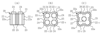
- 1(A) to 1(C) are a side view, a top view, and a bottom view according to a first example of the first assembly element.
- 2(A) to 2(C) are a side view, a top view, and a bottom view according to a second example of the first assembly element.
- 3(A) to 3(C) are a side view, a top view and a bottom view according to a third example of the first assembly element.
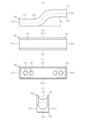
- 4(A) to 4(D) are a side view, a top view and a bottom view according to the first example of the second assembly element.
- 5(A) to 5(C) are a side view, a top view and a bottom view of a second example of the second assembly element.
- FIG. 6(A) to 6(D) are a side view, a top view and a bottom view of a third example of the second assembly element.
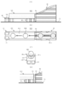
- FIG. 7(A) to FIG. 7(C) are explanatory views of a basic method of installing the second assembly element.
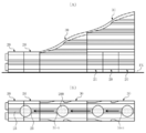
- FIGS. 8A to 8D are a side view and a top view of a first example of the movement path portion.
- 9(A) to 9(D) are a side view and a top view of a second example of the movement path portion.
- FIG. 10(A) and FIG. 10(B) are explanatory views of examples of utilization of the first assembly element shown in FIG.
- An assembled toy set according to the present invention has at least one first assembly element having a first track portion and a second track portion having a mode different from that of the first track portion, and the shape of the first assembly element is different from that of the first assembly element. It is possible to construct a movement path portion that includes at least one different second assembly element and is capable of moving an article by the first track portion and the second track portion in a state where the first assembly element and the second assembly element are provided side by side. Is configured.
- preferred forms of the first assembly element, the second assembly element, the movement path portion, and the like will be described.
- FIGS. 1 to 3 the configuration of the first assembly element included in the assembly toy set according to the present invention will be described with reference to FIGS. 1 to 3.
- the front side of each of FIG. 1A, FIG. 2A, and FIG. 3A is front, the back side is rear, the upper side is upper, the lower side is lower, the left side is left, and the right side is right. It is written as.
- first assembly element 10 shows a first example (first assembly element 10) of the first assembly element.
- the first assembly element 10 has a hexahedron shape having an upper surface 11, four side surfaces (front surface, rear surface, left surface and right surface) 12-1 to 12-4 and a lower surface 13, and a contour of the upper surface 11 and the lower surface 13.
- a chamfered portion 12a extending from the upper surface 11 to the lower surface 13 is formed at each of boundary portions of the four side surfaces 12-1 to 12-4.
- the upper surface 11 of the first assembly element 10 is integrally formed with four convex portions having square lines connecting the respective centers, and the four convex portions constitute the connecting portion 14.
- Each protrusion has a cylindrical shape with the same diameter and the same vertical dimension. The center of each protrusion is located on the diagonal line of the upper surface 11, the distance from the center of the upper surface 11 is equal, and the angular interval is the upper surface. It is 90 degrees in sight.
- each groove extending from the upper surface 11 to the lower surface 13 are formed at the centers of the side surfaces 12-1 to 12-4 of the first assembly element 10 in the left-right direction and the front-rear direction, and each groove forms the first track portion 15.
- the cross-sectional shape of each groove forming the first track portion 15 is described as being an isosceles trapezoid shape having the same size, but it is assumed that each side surface has a different cross-sectional shape. It is also possible.
- the size of the cross-sectional shape of each side surface is different, it is possible to configure the track portion according to the size of the cross-sectional shape, and it is possible to provide various track portions with one assembly element.
- a recess having a columnar (or cylindrical) partition 17 in the center is formed on the lower surface 13 of the first assembly element 10 (that is, the surface facing the surface on which the upper surface 11 is provided).
- the vertical dimension of the concave portion and the partition portion 17 is slightly larger than the vertical dimension of the four convex portions, and moreover, the center of the partition portion 17 coincides with the center of the upper surface 11 in a top view, so the partition portion 27
- the first assembly element 10 has the connecting portion 15 formed of four convex portions on the upper surface 11 side, and the first connected portion 16 formed of a concave portion to which the connecting portion 15 is detachably connected, on the lower surface 13 side.
- Have Four, two, and one of the four convex portions forming the connecting portion 15 can be selectively connected to the first connected portion 16.
- a chamfered portion 12a extending from the upper surface 11 to the lower surface 13 is formed at each of the boundary portions of the four side surfaces 12-1 to 12-4, but the chamfered portion 12a swells depending on the shape of the recess.
- a bulge portion reference numeral omitted
- the first connected portion 16 that is a concave portion is formed by at least a part of the bulging portion. It can also be said that the respective grooves forming the first track portion 15 are located between the adjacent bulging portions, and at least a part of the first track portion 15 is formed by at least a part of the bulging portion. ..
- the first assembly element 20 has a hexahedron shape having an upper surface 21, four side surfaces (front surface, rear surface, left surface and right surface) 22-1 to 22-4 and a lower surface 23, and a contour of the upper surface 21 and the lower surface 23.
- a chamfered portion 22a extending from the upper surface 21 to the lower surface 23 is formed at each boundary portion of the four side surfaces 22-1 to 22-4.
- the upper surface 21 of the first assembly element 20 is integrally formed with four convex portions having square lines connecting the respective centers, and the four convex portions constitute the connecting portion 24.
- Each protrusion has a columnar shape with the same diameter and the same vertical dimension.
- the center of each protrusion is located on the diagonal line of the upper surface 21, the distance between the center of the upper surface 21 is equal, and the angular interval is the upper surface. It is 90 degrees in sight.
- the form of the four protrusions that form the connecting portion 24 is the same as that of the connecting portion 14 of the first assembly element 10.
- a groove extending from the upper surface 21 to the lower surface 23 is formed at the center of each of the side surfaces 22-1 to 22-4 of the first assembly element 20 in the left-right direction and the front-rear direction, and each groove forms the first track portion 25.
- the cross-sectional shape of each groove forming the first track portion 25 is described as being an isosceles trapezoid shape having the same size, but it is assumed that each side surface has a different cross-sectional shape. It is also possible.
- the cross-sectional shape is the same as the first track portion 15 of the first assembly element 10.
- the lower surface 23 (that is, the surface facing the surface on which the upper surface 21 is provided) of the first assembly element 20 is formed with a recess having a cylindrical (or cylindrical) partition 27 in the center.
- the vertical dimension of the concave portion and the partition portion 27 is slightly larger than the vertical dimension of the four convex portions, and moreover, the center of the partition portion 27 coincides with the center of the upper surface 21 in top view.
- the four recesses forming the first connected portion 26 are the same as the first connected portion 16 of the first assembly element 10.
- the first assembly element 20 has the connecting portion 25 formed of four convex portions on the upper surface 21 side, and the first connected portion 26 formed of a concave portion to which the connecting portion 25 is detachably connected on the lower surface 23 side.
- a chamfered portion 22a extending from the upper surface 21 to the lower surface 23 is formed at each of the boundary portions of the four side surfaces 22-1 to 22-4, but the chamfered portion 22a swells according to the shape of the recess.
- a bulge portion reference numeral omitted
- track part 25 is located between adjacent bulging parts, and it can be said that at least one part of the 1st track
- the vertical dimension of the first assembly element 20 excluding the connecting portion 24 is twice the vertical dimension of the first assembly element 10 shown in FIG. 1 excluding the connecting portion 14. Is. That is, the first assembly element 20 is useful when obtaining a vertical dimension that is twice that of the first assembly element 10.
- the first assembly element 3020 has a hexahedral shape having an upper surface 31, four side surfaces (front surface, rear surface, left surface and right surface) 32-1 to 32-4, and a lower surface 33, and the outer contour of the upper surface 31 is a square shape.
- the outer surface of the lower surface 33 has a horizontally long rectangular shape
- the outer surfaces of the front surface 32-1 and the rear surface 32-2 have a right-angled trapezoid shape
- the outer surfaces of the left surface 32-3 and the right surface 32-4 have a vertically long rectangular shape. is there.
- the left surface 32-3 is not a flat surface but a curved surface.
- a chamfer 32a extending from the upper surface 31 to the lower surface 33 is formed at each of the boundary portions of the four side surfaces 32-1 to 32-4.
- the upper surface 31 of the first assembly element 30 is integrally formed with four convex portions having a square line connecting the centers thereof, and the four convex portions constitute a connecting portion 34.
- Each protrusion has a cylindrical shape with the same diameter and the same vertical dimension.
- the center of each protrusion is located on the diagonal line of the upper surface 31, the distance from the center of the upper surface 31 is equal, and the angular interval is the upper surface. It is 90 degrees in sight.
- the mode of the four convex portions forming the connecting portion 34 is the same as the connecting portions 14 and 24 of the first assembling elements 10 and 20.
- a groove 35-1 extending from the upper surface 31 to the lower surface 33 is formed on the right side of the front surface 32-1 and the rear surface 32-2 of the first assembly element 30, and two grooves 35 having a smaller vertical dimension than this are formed. Two -2 are formed on the left side of the groove 35-1. Further, a groove 35-3 extending from the upper surface 31 to the lower surface 33 is formed in the center of the left surface 32-3 of the first assembly element 30 in the front-rear direction, and a groove 35-3 extending from the upper surface 31 to the lower surface 33 of the right surface 32-4 in the front-rear direction. A groove 35-4 extending over the entire length is formed.
- each groove 35-1 to 35-4 is described as being an isosceles trapezoidal shape having the same size, but the cross-sectional shape of each groove should be different. Is also possible.
- only the groove 35-3 of the longest left surface 32-3 in the first assembly element 30 is the first track portion (hereinafter referred to as the first track portion 35-3).
- the grooves other than the groove 35-3 can be used as the first track portion.
- the cross-sectional shape of the first track portion 35-3 is described as being the same as the first track portions 15 and 25 of the first assembly elements 10 and 20, but each track It is also possible to make the sizes of the cross-sectional shapes of the parts different, and it is possible to provide a wider variety of track parts by appropriately assembling different types of assembly elements. ..
- the lower surface 33 (that is, the surface facing the surface on which the upper surface 31 is provided) of the first assembly element 30 is formed with a concave portion having two columnar (or cylindrical) partition portions 37 at right and left intervals.
- the recessed portion constitutes the first connected portion 36.
- the vertical dimension of the concave portion and the partition portion 37 is slightly larger than the vertical dimension of the four convex portions, and moreover, the center of the partition portion 37 on the right side in top view coincides with the center of the upper surface 31, and Since the interval between the partition 37 and the right partition 37 is twice the diameter of the protrusion, four recesses that detachably connect the four protrusions are continuous around the right partition 37.
- four recesses that detachably connect the four convex portions also exist continuously around the right partition 37.
- aspects of the eight recesses forming the first connected portion 36 are the same as those of the first connected portions 16 and 26 of the first assembling elements 10 and 20.
- the first assembly element 30 has the connecting portion 35 formed of four convex portions on the upper surface 31 side, and the first connected portion 36 formed of a concave portion to which the connecting portion 35 is detachably connected on the lower surface 33 side.
- Have Four, two, and one of the four convex portions that configure the connecting portion 35 can be selectively connected to the first connected portion 36.
- a chamfered portion 32a extending from the upper surface 31 to the lower surface 33 is formed at each of the boundary portions of the four side surfaces 32-1 to 32-4.
- the chamfered portion 32a swells according to the shape of the recess.
- a bulge portion reference numeral omitted
- the first connected portion 36 which is a concave portion, is formed by at least a part of the bulging portion.
- each groove forming the first track portion 35 is located between the adjacent bulging portions, and at least a part of the first track portion 35-3 is formed by at least a part of the bulging portion. It can also be said.
- the first assembly element 30 has a vertical dimension excluding the connecting portion 34 that is six times the vertical dimension excluding the connecting portion 14 of the first assembly element 10 shown in FIG.
- the horizontal dimension of 33 is twice the horizontal dimension of the lower surface 13 of the first assembly element 10 shown in FIG. 1, and the left surface 32-3 is curved so that only the left track 32-3 has the first track portion 35-. 3 is provided. That is, the first assembly element 30 is useful when obtaining a vertical dimension that is six times that of the first assembly element 10.
- FIGS. 4 to 6 the configuration of the first assembly element included in the assembly toy set according to the present invention will be described with reference to FIGS. 4 to 6.
- the front side of each of FIG. 4(A), FIG. 5(A), and FIG. 6(A) is front, the back side is rear, the upper side is upper, the lower side is lower, the left side is left, and the right side is right. It is written as.
- FIGS. 4A to 4D show a first example (second assembly element 110) of the second assembly element.
- the second assembly element 110 has a hexahedron shape having an upper surface 111, four side surfaces (front surface, rear surface, left surface and right surface) 112-1 to 112-4 and a lower surface 113, and the upper surface 111 and the four side surfaces 112 are included.
- -1 to 112-4 and the outer surface of the lower surface 113 are horizontally long rectangular shapes.
- a groove extending from the left surface 112-3 to the right surface 112-4 is formed in the center of the upper surface 111 of the second assembly element 110 in the front-rear direction, and the groove constitutes the second track portion 114.
- the cross-sectional shape of the groove is semicircular, and the maximum width and the maximum depth thereof are the same as those of the first track portions 15, 25 and 35-3 of the above-mentioned first assembly element 10, 20 and 30. Greater than maximum width and maximum depth.
- the second assembly element 110 On the lower surface 113 of the second assembly element 110 (that is, the surface facing the surface on which the second track portion 110 is provided), there are five columnar (or cylindrical) partition portions 116 at right and left intervals. A concave portion is formed, and the concave portion constitutes the second connected portion 115.
- the vertical dimension of the concave portion and the partition portion 116 is slightly larger than the vertical dimension of the four convex portions forming the connecting portions 14, 24 and 34 of the first assembly elements 10, 20 and 30 described above, and the concave portion
- the front-rear dimension and the diameter and position of the partition portion 116 are the same as the front-rear dimension of the recesses and the partition portions 17, 27 which form the first connected portions 16, 26 and 36 of the first assembly elements 10, 20 and 30 described above.
- the second assembly element 120 has a hexahedron shape having an upper surface 121, four side surfaces (front surface, left surface, inner surface and outer surface) 122-1 to 122-4, and a lower surface 123.
- a curved groove extending from the front surface 122-1 to the left surface 122-2 is formed in the center of the upper surface 121 of the second assembly element 120, and the groove constitutes the second track portion 124.
- the cross-sectional shape of the groove is semicircular, and its maximum width and maximum depth are determined from the maximum width and maximum depth of the first track portions 15, 25 and 35-3 of the first assembly elements 10, 20 and 30 described above. Is also big.
- the cross-sectional shape of the second track portion 124 is the same as the second track portion 114 of the second assembly element 110.
- the lower surface 123 of the second assembly element 120 (that is, the surface opposite to the surface on which the second track portion 120 is provided) is provided with a recess having two columnar partition portions 126 in the front surface portion and the left surface portion, respectively. It is formed and the concave portion constitutes the second connected portion 125.
- the vertical dimension of the concave portion and the partition portion 126 is slightly larger than the vertical dimension of the four convex portions forming the connecting portions 14, 24 and 34 of the first assembly elements 10, 20 and 30 described above, and the concave portion
- the left-right dimension of the front surface side portion and the front-rear dimension of the left surface side portion and the diameter and position of the partition portion 126 constitute the first connected portions 16, 26 and 36 of the first assembly elements 10, 20 and 30 described above.
- the above-mentioned first assembly element 10 Since the dimension in the front-rear direction of the concave portion and the diameter and position of the partition portions 17, 27 and 37 are the same, the above-mentioned first assembly element 10, around the partition portions 126 (excluding the inner partition portion 126), There are continuous four recesses (see the circle drawn by a two-dot chain line in FIG. 5C) that detachably connects the four protrusions that form the connection parts 14, 24 and 34 of 20 and 30. To do.
- the second assembly element 130 has a hexahedron shape having an upper surface 131, four side surfaces (front surface, rear surface, left surface and right surface) 132-1 to 113-4 and a lower surface 133, and the upper surface 131 and the left surface 132-3.
- the outer contours of the right surface 132-4 and the lower surface 133 are horizontally long rectangular shapes, and the outer contours of the front surface 132-1 and the rear surface 132-2 are curved at the center, and the left surface portion and the right surface portion have a dimension Vd.
- this dimension Vd matches the vertical dimension of the first assembly element 20 excluding the connecting portion 24.
- a groove extending from the left surface 132-3 to the right surface 132-4 is formed in the center of the upper surface 131 of the second assembly element 130, and the groove constitutes the second track portion 134.
- the cross-sectional shape of the groove is semicircular, and its maximum width and maximum depth are determined from the maximum width and maximum depth of the first track portions 15, 25 and 35-3 of the first assembly elements 10, 20 and 30 described above. Is also big.
- the cross-sectional shape of the second track portion 134 is the same as the second track portions 114 and 124 of the second assembly elements 110 and 120.
- the concave portion constitutes the second connected portion 135.
- the vertical dimension of the concave portion and the partition portion 136 is slightly larger than the vertical dimension of the four convex portions forming the connecting portions 14, 24 and 34 of the first assembly elements 10, 20 and 30 described above, and the concave portion
- the front-rear dimension and the diameter and position of the partition 136 are the front-rear dimension and the partition 17, 27 of the recessed portion forming the first connected portions 16, 26, 36 of the first assembly elements 10, 20 and 30 described above.
- each compartment 136 (excluding the inner compartment 136) constitutes a connection 14, 24 and 34 of the aforementioned first assembly element 10, 20 and 30.
- There are continuous four recesses (see the circle drawn with a two-dot chain line in FIG. 6C) that detachably connects the four protrusions.
- FIG. 7(A) shows two second assembling elements 110 arranged linearly by using one first assembling element 10, which is the second assembling element of the second assembling element 110 on the left side.
- the rightmost two recesses of the connected portion 115 are connected to the left two of the four protrusions forming the connecting portion 14 of the first assembly element 10, and the second recess of the right second assembly element 110 is connected. This can be done by connecting the two leftmost recesses of the connected portion 115 to the right two of the four protrusions forming the connecting portion 14 of the first assembly element 10.
- the second track portion 114 of the second assembly element 110 on the left side and the right surface of the second assembly element 110 on the right side can form a linearly continuous track portion.
- FIG. 7B shows that two second assembly elements 110 are linearly installed by using the two first assembly elements 10, and the installation is the second assembly element 110 on the left side.
- the rightmost four recesses of the connected portion 115 are connected to the four convex portions of the connecting portion 14 of the first assembly element 10, and the leftmost portion of the second connected portion 115 of the right second assembly element 110 is connected.
- Are connected to the four protrusions that form the connecting portion 14 of the first assembly element 10, and the right surface of the second assembly element 110 on the left side and the left surface of the second assembly element 110 on the right side are aligned with each other. It can be performed by contacting or approaching with.
- the second track portion 114 of the second assembly element 110 on the left side and the right surface of the second assembly element 110 on the right side can form a linearly continuous track portion.
- FIG. 7(C) shows two second assembling elements 110 arranged side by side using one first assembling element 10 such that an angle difference is generated. After being rotated by 45 degrees, one recess at the rightmost corner of the second connected portion 115 of the second assembly element 110 on the left side is provided with four protrusions forming the connecting portion 14 of the first assembly element 10. Of the second assembly element 110 on the right side, one recess at the leftmost corner of the second connected portion 115 of the second assembly element 110 on the right side constitutes the connection portion 14 of the first assembly element 10. This can be done by connecting to one of the four ridges on the right side.
- the right surface of the second assembly element 110 on the left side and the left surface of the second assembly element 110 on the right side approach each other with an angle difference, so that the second track portion 114 of the second assembly element 110 on the left side and the second surface section on the right side
- the second track portion 114 of the assembly element 110 and the connecting portion 14 located between the adjacent second assembly elements 110 can form a continuous track portion such that the track direction changes at a predetermined angle.
- the first assembling element 10 is changed to the above-mentioned first assembling element 20 or 30, or the second assembling element 110 is changed to the above-mentioned second assembling element 120 or 130. The same can be done in case of failure. Further, as can be seen from FIG. 7(B), the above-mentioned first assembly elements 10, 20 and 30 are adjusted by adjusting the height positions of the above-mentioned second assembly elements 110, 120 and 130, so that the second track It can also be used to adjust the height position of the.
- the movement path portions 310 and 320 described later are intended to move the spherical article 200 that is movable and rollable by its own weight.
- the spherical article 200 illustrated in FIGS. 8 and 9 has a diameter smaller than the maximum width of the first track portions 15, 25 and 35-3, and the second track portion 114, Greater than the maximum width of 124 and 134.
- the second track portion 114 of the second assembly element 110 is suitable for linearly moving the spherical article 200
- the second track portion 124 of the second assembly element 120 is The spherical article 200 is suitable for moving in a non-linear manner, for example, changing the moving direction
- the second assembly element 130 is suitable for performing movement involving height changes.
- FIG. 8A shows a first example of the movement route portion (movement route portion 310).
- the movement path portion 310 includes two first assembly elements 10, three first assembly elements 20, one second assembly element 110, and one second assembly element 120. There is.
- the movement path portion 310 is constructed by connecting the two first assembling elements 10 to each other and connecting the two first assembling elements 10 to the second assembling element on the left side of the four convex portions forming the connecting portion 14 of the upper first assembling element 10.
- 110 is connected to the rightmost two recesses of the second connected portion 115, and the right two are connected to the leftmost two recesses of the second connected portion 125 of the second assembly element 120,
- the four protrusions forming the connecting portion 24 of the first assembly element 20 are connected to the leftmost four recesses of the second connected portion 115 of the second assembly element 110 to form a two-assembly first assembly element.
- the lower surface of 10 and the lower surface of one first assembly element 20 are placed on the flat surface FS, and the two first assembly elements 20 are connected to each other so that each first track portion 25 faces upward. This can be done by tilting and mounting on the flat surface FS and bringing the right ends of the two connected first assembly elements 20 into contact with the left ends of the second assembly element 110 and the first assembly element 20.
- the movement path portion 310 includes two second track portions 124 of the second assembly element 120, a second track portion 114 of the second assembly element 110, and two second track portions 124 from the right to the left in FIG. 8B. Since a continuous track portion (reference numeral omitted) composed of the first track portion 25 of the first assembly element 20 is arranged side by side, the spherical article 200 sent to the second track portion 124 of the second assembly element 120 is It can be moved as indicated by an arrow in FIG.
- the spherical article 20 moves in the different contact state with the first track portion 25 and the second track portions 124 and 114. ..
- the spherical article 200 moves while rolling on the second track portions 124 and 114 in a one-point contact state, moves from the second track portion 114 to the first track portion 25, and has two continuous first tracks.
- the part 25 can move while rolling in a two-point contact state.
- the first track portion 25 of the first assembly element 20 is positioned higher than the height at which the second track portion 114 of the second assembly element 110 configuring the movement path portion 310 is located. Because of the low height, the spherical article 200 can be transferred from the second track portion 114 to the first track portion 25 without any trouble.
- FIG. 8(A) and 8(B) show the case where the right end of the two connected first assembly elements 20 is in contact with the left ends of the second assembly element 110 and the first assembly element 20.
- FIG. 8(D) even if a gap GA is generated between the right end of the first assembly element 20 and the left ends of the second assembly element 110 and the first assembly element 20 that are connected in two, If the gap GA is small, for example, if the gap GA is 1 ⁇ 2 or less of the diameter of the spherical article 200, the spherical article 200 can be transferred from the second track portion 114 to the first track portion 25 without any trouble. ..
- FIG. 9(A) shows a second example (moving route unit 320) of the moving route unit.
- the movement path portion 320 is composed of two first assembly elements 10, one first assembly element 30, and one second assembly element 110.
- the movement path part 320 is constructed by connecting the four convex parts forming the connecting part 14 of one first assembly element 10 to the four rightmost recesses of the second connected part 115 of the second assembly element 110. Then, the right two of the four convex portions forming the connecting portion 14 of the one first assembly element 10 are connected to the leftmost two recesses of the second connected portion 125 of the second assembly element 110. Then, the lower surface of each one of the first assembly elements 10 is placed on the flat surface FS, and the one first assembly element 30 is tilted by 90 degrees so that the first track portion 35-3 faces upward. This can be done by placing it on the flat surface FS and bringing the connecting portion 34 of the first assembly element 30 into contact with the right ends of the second assembly element 110 and the first assembly element 10.
- the spherical article 20 moves while rolling on the first track portion 35-3 in a two-point contact state, transitions from the first track portion 35-3 to the second track portion 114, and the second track portion 114. Can move while rolling in a one-point contact state.
- the second track portion 114 of the second assembly element 110 is higher than the height at which the first track portion 35-3 of the first assembly element 30 forming the movement path portion 320 is located. Since the position where is located is low, the spherical article 200 can be transferred from the first track portion 35-3 to the second track portion 114 without any trouble.
- FIG. 9(A) and 9(B) show the connecting portion 34 of the first assembly element 30 in contact with the right ends of the second assembly element 110 and the first assembly element 10, respectively.
- FIG. 9(D) even if a gap GA different from the above gap is formed between the connecting portion 34 of the first assembly element 30 and the right ends of the second assembly element 110 and the first assembly element 10, If the gap GA is small, for example, if the sum of the gap and the gap GA is 1/2 or less of the diameter of the spherical article 200, the spherical article 200 from the first track portion 35-3 to the second track portion 114. Can be performed without any trouble.
- the movement path portion is constructed by a combination of the first assembly element (10, 20 and 30) and the second assembly element (110, 120 and 130) other than the combination shown in FIG. 8 or 9. It is also possible to move the spherical object 200 from the first track part (15, 25 and 35-3) to the second track part (114, 124 and 134) and the second track part (114). , 124 and 134) to the first track portion (15, 25 and 35-3) can be moved in the same manner as described above.
- first assembly element 30 can also be utilized as illustrated in FIG. 10, and the application example is composed of two first assembly elements 30 and five first assembly elements 20.
- two first assembly elements 20 are connected to each other, and each first track portion 25 is placed on the flat surface FS with an inclination of 90° so that each first track portion 25 faces upward.
- the four convex portions forming the connecting portion 34 are connected to the first assembling element 20 on the right side of the first assembling element 20.
- the three first assembly elements 20 are connected to the four recesses of the first connected portion 26, and each first track portion 25 is mounted on the flat surface FS with an inclination of 90 degrees so as to face upward.
- the four convex portions forming the connecting portion 24 of the first assembly element 20 on the left side of the three connected pieces are provided on the lower side of the eight recesses of the first connected portion 36 of the first assembly element 30.
- the second first assembly element 30 is tilted by 90 degrees so that the first track portion 35-3 faces upward, and the second first assembly element 30 is placed on the first assembly element 20 of three connections. This can be performed by connecting the four convex portions forming the connecting portion 34 to the remaining four recesses of the first connected portion 36 of the second first assembly element 30.
- At least one first assembly element A first track portion (15, 25 and 35-3) of (10, 20 and 30) and a second track portion (114, 124 and 134) of at least one second assembly element (110, 120 and 130); Since it is possible to construct a moving path portion (310 and 320, etc.) that can move the spherical article 200 according to the preference, compared to the case of constructing a moving path portion using only the orbit portion of the same aspect, It is possible to improve the fun. Further, by further using the first assembling elements (10, 20 and 30) together, it is possible to construct more various movement path portions.
- FIG. 1 illustrates an example in which the first track portion 15 is provided on each side surface 12-1 to 12-4 of the first assembly element 10, and in FIG. 2, each side surface 22- of the first assembly element 20.
- the first track portion 25 is provided on 1 to 22-4 is illustrated, in the first assembly element 10, the first track portion is provided on at least one of the four side surfaces 12-1 to 12-4. 15 may be provided, or even in the first assembly element 20, the first track portion 25 may be provided on at least one of the four side surfaces 22-1 to 22-4.
- FIGS. 1 to 3 exemplify the connecting portions 14, 24 and 35 formed of four convex portions, and the first connected portions 16, 26 and 36 corresponding to the connecting portions 14, 24 and 35.
- the second connected portions 115, 125 and 135 corresponding to the connecting portions 14, 24 and 35 are illustrated, but the connecting portion is composed of two convex portions, and The connecting portion and the second connected portion may correspond to this connecting portion.
- grooves having an isosceles trapezoidal cross section are shown as the first track portions 15, 25, and 35-3, but instead, grooves having a semicircular cross section. It is also possible to use isosceles triangular grooves, rectangular grooves, or the like. In addition, although grooves having a semicircular cross section are shown as the second track portions 114, 124, and 134 in FIGS. 4 to 6, instead, grooves having an isosceles trapezoidal cross section or an isosceles side are used instead. It is also possible to use a triangular groove, a rectangular groove, or the like.
- a non-spherical article can also be an object to be moved if it can be moved by its own weight. It is also possible to use a movable model vehicle or a self-propelled model vehicle as an article. For example, when the model vehicle is to be moved, a groove having a rectangular cross section that can guide the outside of the model vehicle as the second track portions (114, 124 and 134) of the second assembly element (110, 120 and 130). And adopts a ridge having a rectangular cross section that can guide the inside of the left and right wheels of the model vehicle as the first track portion (15, 25 and 35-3) of the first assembly element (10, 20 and 30). Good.
Landscapes
- Engineering & Computer Science (AREA)
- Multimedia (AREA)
- Toys (AREA)
Abstract
【課題】興趣性を向上させた組立玩具セットを提供する。 【解決手段】組立玩具セットは、第1軌道部25を有する2個の第1組立要素20と、第2軌道部114を有し、前記第1組立要素とは形状が異なる第2組立要素110と、第2軌道部124を有する第2組立要素120とを含み、2個の第1組立要素20と第2組立要素110および120とを併設した状態において第1軌道部25と第2軌道部114および124とによって物品200を移動可能な移動経路部310を構築できるように構成されている。
Description
本発明は、物品を移動可能な移動経路部を構築可能な組立玩具セットと、当該組立玩具セット用の組立要素に関する。
後記特許文献1には、複数の結合ピンと3以上の溝を上面に有し、かつ、複数のソケットを下面に有するブロックを用いて、球体が転がるコースを構築できるようにしたブロック玩具が開示されている。このブロック玩具は複数の同形状のブロックを組み合わせて各々の溝を利用してコースを構築するものであるため、十分な興趣を使用者に供与することは難しい。
本発明が解決しようとする課題は、興趣性を向上させた組立玩具セットおよび組立玩具セット用の組立要素を提供することにある。
本発明に係る組立玩具セットは、第1軌道部を有する少なくとも1個の第1組立要素と、前記第1軌道部と態様が異なる第2軌道部を有し、前記第1組立要素とは形状が異なる少なくとも1個の第2組立要素とを含み、前記第1組立要素と前記第2組立要素とを併設した状態において前記第1軌道部と前記第2軌道部とによって物品を移動可能な移動経路部を構築できるように構成されている。また、本発明に係る組立玩具セット用の組立要素は、前掲の第1組立要素、または、前掲の第2組立要素である。
本発明に係る組立玩具および組立玩具セット用の組立要素によれば、興趣性を向上させた組立玩具セットおよび組立玩具セット用の組立要素を提供することができる。
本発明に係る組立玩具セットは、第1軌道部を有する少なくとも1個の第1組立要素と、第1軌道部と態様が異なる第2軌道部を有し、え第1組立要素とは形状が異なる少なくとも1個の第2組立要素とを含み、第1組立要素と第2組立要素とを併設した状態において第1軌道部と第2軌道部とによって物品を移動可能な移動経路部を構築できるように構成されている。以下に、第1組立要素、第2組立要素および移動経路部等の好ましい形態について説明する。
《第1組立要素》
まず、図1~図3を用いて、本発明に係る組立玩具セットに含まれる第1組立要素の構成について説明する。ここでは、便宜上、図1(A)と図2(A)と図3(A)それぞれの手前側を前、奥側を後、上側を上、下側を下、左側を左、右側を右と表記する。
まず、図1~図3を用いて、本発明に係る組立玩具セットに含まれる第1組立要素の構成について説明する。ここでは、便宜上、図1(A)と図2(A)と図3(A)それぞれの手前側を前、奥側を後、上側を上、下側を下、左側を左、右側を右と表記する。
図1(A)~図1(C)は第1組立要素の第1例(第1組立要素10)を示す。この第1組立要素10は、上面11と4つの側面(前面、後面、左面および右面)12-1~12-4と下面13とを有する6面体状であって、上面11と下面13の外郭は正方形状であり、4つの側面12-1~12-4の外郭は横長の長方形状である。また、4つの側面12-1~12-4の境界箇所それぞれには、上面11から下面13に及ぶ面取り部12aが形成されている。
第1組立要素10の上面11には、各々の中心を結ぶ線が正方形となる4個の凸部が一体に形成されていて、当該4つの凸部は連結部14を構成している。各凸部は直径が等しく、かつ、上下方向寸法が等しい円柱状であり、各凸部の中心は上面11の対角線上に位置していて上面11の中心との間隔は等しく、角度間隔は上面視において90度である。
第1組立要素10の各側面12-1~12-4の左右方向および前後方向の中央には、上面11から下面13に及ぶ溝が形成されていて、当該溝それぞれは第1軌道部15を構成している。本実施の形態においては、第1軌道部15を構成する各溝の断面形状はサイズが等しい等脚台形状であるものとして記載しているが、各側面の断面形状のサイズが異なる溝とすることも可能である。各側面の断面形状のサイズが異なる場合には、断面形状のサイズに応じた軌道部を構成可能であり、1つの組立要素で多様な軌道部を提供することが可能となる。
第1組立要素10の下面13(即ち、上面11が設けられた面と相対する面)には、円柱状(または円筒状)の区画部17を中央に有する凹部が形成されていて、当該凹部は第1被連結部16を構成している。凹部および区画部17の上下方向寸法は前記4つの凸部の上下方向寸法よりも僅かに大きく、しかも、上面視において区画部17の中心は上面11の中心と一致しているため、区画部27の周囲には前記4つの凸部を着脱可能に連結する4つの凹所が連続して存在する。
すなわち、第1組立要素10は、4つの凸部から成る連結部15を上面11側に有するとともに、当該連結部15が着脱可能に連結する凹部から成る第1被連結部16を下面13側に有している。第1被連結部16には、連結部15を構成する4つの凸部のうちの4つ、2つおよび1つが選択的に連結可能である。ここで、4つの側面12-1~12-4の境界箇所それぞれには、上面11から下面13に及ぶ面取り部12aが形成されているが、面取り部12aには、凹部の形状に応じて膨らんだ膨出部(符号省略)が形成されている。即ち、凹部から成る第1被連結部16は、この膨出部の少なくとも一部により形成されているともいえる。また、第1軌道部15を構成する各溝は、隣接する膨出部の間に位置し、第1軌道部15の少なくとも一部は、膨出部の少なくとも一部により形成されているともいえる。
図2(A)~図2(C)は第1組立要素の第2例(第1組立要素20)を示す。この第1組立要素20は、上面21と4つの側面(前面、後面、左面および右面)22-1~22-4と下面23とを有する6面体状であって、上面21と下面23の外郭は正方形状であり、4つの側面22-1~22-4の外郭は横長の長方形状である。また、4つの側面22-1~22-4の境界箇所それぞれには、上面21から下面23に及ぶ面取り部22aが形成されている。
第1組立要素20の上面21には、各々の中心を結ぶ線が正方形となる4個の凸部が一体に形成されていて、当該4つの凸部は連結部24を構成している。各凸部は直径が等しく、かつ、上下方向寸法が等しい円柱状であり、各凸部の中心は上面21の対角線上に位置していて上面21の中心との間隔は等しく、角度間隔は上面視において90度である。本実施の形態においては、、連結部24を構成する4つの凸部の態様は、前記第1組立要素10の連結部14と同じである。
第1組立要素20の各側面22-1~22-4の左右方向および前後方向の中央には、上面21から下面23に及ぶ溝が形成されていて、当該溝それぞれは第1軌道部25を構成している。本実施の形態においては、第1軌道部25を構成する各溝の断面形状はサイズが等しい等脚台形状であるものとして記載しているが、各側面の断面形状のサイズが異なる溝とすることも可能である。また、当該断面形状は前記第1組立要素10の第1軌道部15と同じである。
第1組立要素20の下面23(即ち、上面21が設けられた面と相対する面)には、円柱状(または円筒状)の区画部27を中央に有する凹部が形成されていて、当該凹部は第1被連結部26を構成している。凹部および区画部27の上下方向寸法は前記4つの凸部の上下方向寸法よりも僅かに大きく、しかも、上面視において区画部27の中心は上面21の中心と一致しているため、区画部27の周囲には前記4つの凸部を着脱可能に連結する4つの凹所が連続して存在する。本実施の形態においては、、第1被連結部26を構成する4つの凹所の態様は、前記第1組立要素10の第1被連結部16と同じである。
すなわち、第1組立要素20は、4つの凸部から成る連結部25を上面21側に有するとともに、当該連結部25が着脱可能に連結する凹部から成る第1被連結部26を下面23側に有している。第1被連結部26には、連結部25を構成する4つの凸部のうちの4つ、2つおよび1つが選択的に連結可能である。ここで、4つの側面22-1~22-4の境界箇所それぞれには、上面21から下面23に及ぶ面取り部22aが形成されているが、面取り部22aには、凹部の形状に応じて膨らんだ膨出部(符号省略)が形成されている。即ち、凹部から成る第1被連結部26は、この膨出部の少なくとも一部により形成されているともいえる。また、第1軌道部25を構成する各溝は、隣接する膨出部の間に位置し、第1軌道部25の少なくとも一部は、膨出部の少なくとも一部により形成されているともいえる。
本実施の形態においては、第1組立要素20は、その連結部24を除く上下方向寸法を、図1に示した第1組立要素10の連結部14を除く上下方向寸法の2倍としたものである。すなわち、第1組立要素20は、第1組立要素10の2倍の上下方向寸法を得るときに有用である。
図3(A)~図3(C)は第1組立要素の第3例(第1組立要素30)を示す。この第1組立要素3020は、上面31と4つの側面(前面、後面、左面および右面)32-1~32-4と下面33とを有する6面体状であって、上面31の外郭は正方形状であり、下面33の外郭は横長の長方形状であり、前面32-1および後面32-2の外郭は直角台形状であり、左面32-3および右面32-4の外郭は縦長の長方形状である。本実施の形態においては、、左面32-3は平坦な面でなく、湾曲した面から成る。また、4つの側面32-1~32-4の境界箇所それぞれには、上面31から下面33に及ぶ面取り部32aが形成されている。
第1組立要素30の上面31には、各々の中心を結ぶ線が正方形となる4個の凸部が一体に形成されていて、当該4つの凸部は連結部34を構成している。各凸部は直径が等しく、かつ、上下方向寸法が等しい円柱状であり、各凸部の中心は上面31の対角線上に位置していて上面31の中心との間隔は等しく、角度間隔は上面視において90度である。本実施の形態においては、、連結部34を構成する4つの凸部の態様は、前記第1組立要素10および20の連結部14および24と同じである。
第1組立要素30の前面32-1および後面32-2の右側には、上面31から下面33に及ぶ溝35-1が形成されている他、これよりも上下方向寸法が小さい2つの溝35-2が溝35-1の左側に2つ形成されている。また、第1組立要素30の左面32-3の前後方向中央には、上面31から下面33に及ぶ溝35-3が形成され、右面32-4の前後方向中央には、上面31から下面33に及ぶ溝35-4が形成されている。本実施の形態においては、各溝35-1~35-4の断面形状はサイズが等しい等脚台形状であるものとして記載しているが、各溝の断面形状のサイズを異なるようにすることも可能である。が、また、本実施の形態においては、第1組立要素30にあっては最も長い左面32-3の溝35-3のみが第1軌道部(以下、第1軌道部35-3と言う)としているが、組立要素同士のレイアウトを工夫することで、溝35-3以外の溝を第1軌道部とも可能である。また、本実施の形態においては、第1軌道部35-3の断面形状は前記第1組立要素10および20の第1軌道部15および25と同じであるものとして記載しているが、各軌道部の断面形状のサイズが異なるようにすることも可能であり、種類の異なる組立要素を適宜組み立てることにより、より多様な軌道部を提供することが可能となる。。
第1組立要素30の下面33(即ち、上面31が設けられた面と相対する面)には、円柱状(または円筒状)の区画部37を左右に間隔をおいて2個有する凹部が形成されていて、当該凹部は第1被連結部36を構成している。凹部および区画部37の上下方向寸法は前記4つの凸部の上下方向寸法よりも僅かに大きく、しかも、上面視における右側の区画部37の中心は上面31の中心と一致しており、左側の区画部37と右側の区画部37との間隔が凸部の直径の2倍であるため、右側の区画部37の周囲には前記4つの凸部を着脱可能に連結する4つの凹所が連続して存在し、右側の区画部37の周囲にも前記4つの凸部を着脱可能に連結する4つの凹所が連続して存在する。本実施の形態においては、、第1被連結部36を構成する8つの凹所の態様は、前記第1組立要素10および20の第1被連結部16および26と同じである。
すなわち、第1組立要素30は、4つの凸部から成る連結部35を上面31側に有するとともに、当該連結部35が着脱可能に連結する凹部から成る第1被連結部36を下面33側に有している。第1被連結部36には、連結部35を構成する4つの凸部のうちの4つ、2つおよび1つが選択的に連結可能である。ここで、4つの側面32-1~32-4の境界箇所それぞれには、上面31から下面33に及ぶ面取り部32aが形成されているが、面取り部32aには、凹部の形状に応じて膨らんだ膨出部(符号省略)が形成されている。即ち、凹部から成る第1被連結部36は、この膨出部の少なくとも一部により形成されているともいえる。また、第1軌道部35を構成する各溝は、隣接する膨出部の間に位置し、第1軌道部35-3の少なくとも一部は、膨出部の少なくとも一部により形成されているともいえる。
本実施の形態においては、第1組立要素30は、その連結部34を除く上下方向寸法を、図1に示した第1組立要素10の連結部14を除く上下方向寸法の6倍とし、下面33の左右方向寸法を図1に示した第1組立要素10の下面13の左右方向寸法の2倍とし、左面32-3を湾曲したものとして当該左面32-3のみに第1軌道部35-3を設けたものである。すなわち、第1組立要素30は、第1組立要素10の6倍の上下方向寸法を得るときに有用である。
《第2組立要素》
次に、図4~図6を用いて、本発明に係る組立玩具セットに含まれる第1組立要素の構成について説明する。ここでは、便宜上、図4(A)と図5(A)と図6(A)それぞれの手前側を前、奥側を後、上側を上、下側を下、左側を左、右側を右と表記する。
次に、図4~図6を用いて、本発明に係る組立玩具セットに含まれる第1組立要素の構成について説明する。ここでは、便宜上、図4(A)と図5(A)と図6(A)それぞれの手前側を前、奥側を後、上側を上、下側を下、左側を左、右側を右と表記する。
図4(A)~図4(D)は第2組立要素の第1例(第2組立要素110)を示す。この第2組立要素110は、上面111と4つの側面(前面、後面、左面および右面)112-1~112-4と下面113とを有する6面体状であって、上面111と4つの側面112-1~112-4と下面113の外郭は横長の長方形状である。
第2組立要素110の上面111の前後方向中央には、左面112-3から右面112-4に及ぶ溝が形成されていて、当該溝は第2軌道部114を構成している。本実施の形態においては、溝の断面形状は半円状であり、その最大幅および最大深さは、前述の第1組立要素10、20および30の第1軌道部15、25および35-3の最大幅と最大深さよりも大きい。
第2組立要素110の下面113(即ち、第2軌道部110が設けられた面と相対する面)には、円柱状(または円筒状)の区画部116を左右に間隔をおいて5個有する凹部が形成されていて、当該凹部は第2被連結部115を構成している。凹部および区画部116の上下方向寸法が、前述の第1組立要素10、20および30の連結部14、24および34を構成する4つの凸部の上下方向寸法よりも僅かに大きく、しかも、凹部の前後方向寸法と区画部116の直径および位置が、前述の第1組立要素10、20および30の第1被連結部16、26および36を構成する凹部の前後方向寸法と区画部17、27および37の直径および位置と同じであるため、各区画部116の周囲には、前述の第1組立要素10、20および30の連結部14、24および34を構成する4つの凸部を着脱可能に連結する4つの凹所(図4(C)に2点鎖線で描いた円を参照)が連続して存在する。
図5(A)~図5(C)は第2組立要素の第2例(第2組立要素120)を示す。この第2組立要素120は、上面121と4つの側面(前面、左面、内側面および外側面)122-1~122-4と下面123とを有する6面体状であって、上面121および下面123の外郭はL字状であり、前面122-1および左面112-2の外郭は横長の長方形状であって前面122-1と左面112-2には90度の角度差がある。
第2組立要素120の上面121の中央には、前面122-1から左面122-2に及ぶ湾曲した溝が形成されていて、当該溝は第2軌道部124を構成している。溝の断面形状は半円状であり、その最大幅および最大深さは、前述の第1組立要素10、20および30の第1軌道部15、25および35-3の最大幅と最大深さよりも大きい。本実施の形態においては、第2軌道部124の断面形状は前記第2組立要素110の第2軌道部114と同じである。
第2組立要素120の下面123(即ち、第2軌道部120が設けられた面と相対する面)には、円柱状の区画部126を前面側部分と左面側部分に各々2個有する凹部が形成されていて、当該凹部は第2被連結部125を構成している。凹部および区画部126の上下方向寸法が、前述の第1組立要素10、20および30の連結部14、24および34を構成する4つの凸部の上下方向寸法よりも僅かに大きく、しかも、凹部の前面側部分の左右方向寸法および左面側部分の前後方向寸法と区画部126の直径および位置が、前述の第1組立要素10、20および30の第1被連結部16、26および36を構成する凹部の前後方向寸法と区画部17、27および37の直径および位置と同じであるため、各区画部126(内側の区画部126を除く)の周囲には、前述の第1組立要素10、20および30の連結部14、24および34を構成する4つの凸部を着脱可能に連結する4つの凹所(図5(C)に2点鎖線で描いた円を参照)が連続して存在する。
図6(A)~図6(D)は第2組立要素の第3例(第2組立要素130)を示す。この第2組立要素130は、上面131と4つの側面(前面、後面、左面および右面)132-1~113-4と下面133とを有する6面体状であって、上面131と左面132-3と右面132-4と下面133の外郭は横長の長方形状であり、前面132-1と後面132-2の外郭は中央が湾曲した形状であって左面側部分と右面側部分には寸法Vdの高低差がある。本実施の形態においては、、この寸法Vdは、第1組立要素20の連結部24を除く上下方向寸法に一致している。
第2組立要素130の上面131の中央には、左面132-3から右面132-4に及ぶ溝が形成されていて、当該溝は第2軌道部134を構成している。溝の断面形状は半円状であり、その最大幅および最大深さは、前述の第1組立要素10、20および30の第1軌道部15、25および35-3の最大幅と最大深さよりも大きい。本実施の形態においては、第2軌道部134の断面形状は前記第2組立要素110および120の第2軌道部114および124と同じである。
第2組立要素130の下面133(即ち、第2軌道部130が設けられた面と相対する面)には、円柱状の区画部136を左面側部分と右面側部分に各々2個有する凹部が形成されていて、当該凹部は第2被連結部135を構成している。凹部および区画部136の上下方向寸法が、前述の第1組立要素10、20および30の連結部14、24および34を構成する4つの凸部の上下方向寸法よりも僅かに大きく、しかも、凹部の前後方向寸法と区画部136の直径および位置が、前述の第1組立要素10、20および30の第1被連結部16、26および36を構成する凹部の前後方向寸法と区画部17、27および37の直径および位置と同じであるため、各区画部136(内側の区画部136を除く)には、前述の第1組立要素10、20および30の連結部14、24および34を構成する4つの凸部を着脱可能に連結する4つの凹所(図6(C)に2点鎖線で描いた円を参照)が連続して存在する。
《第2組立要素の基本的な併設方法》
次に、図7を用いて、前述の第2組立要素110、120および130の基本的な併設方法について説明する。
次に、図7を用いて、前述の第2組立要素110、120および130の基本的な併設方法について説明する。
図7(A)は2個の第2組立要素110を1個の第1組立要素10を用いて直線的に併設したものであって、当該併設は、左側の第2組立要素110の第2被接続部115の最も右側の2つの凹所を第1組立要素10の連結部14を構成する4つの凸部のうちの左側の2つに連結し、右側の第2組立要素110の第2被接続部115の最も左側の2つの凹所を第1組立要素10の連結部14を構成する4つの凸部のうちの右側の2つに連結する、ことによって行うことができる。
この併設方法では、左側の第2組立要素110の右面と右側の第2組立要素110の左面が整合した状態で接触または近接するため、左側の第2組立要素110の第2軌道部114と右側の第2組立要素110の第2軌道部114とが直線的に連続した軌道部を形成することができる。
図7(B)は2個の第2組立要素110を2個の第1組立要素10を用いて直線的に併設したものであって、当該併設は、左側の第2組立要素110の第2被接続部115の最も右側の4つの凹所を第1組立要素10の連結部14を構成する4つの凸部に連結し、右側の第2組立要素110の第2被接続部115の最も左側の4つの凹所を第1組立要素10の連結部14を構成する4つの凸部に連結して、左側の第2組立要素110の右面と右側の第2組立要素110の左面とを整合状態で接触または近接させる、ことによって行うことができる。
この併設方法では、左側の第2組立要素110の右面と右側の第2組立要素110の左面が整合した状態で接触または近接するため、左側の第2組立要素110の第2軌道部114と右側の第2組立要素110の第2軌道部114とが直線的に連続した軌道部を形成することができる。
図7(C)は2個の第2組立要素110を1個の第1組立要素10を用いて角度差が生じるように併設したものであって、当該併設は、第1組立要素10を上面視で45度回転させておき、左側の第2組立要素110の第2被接続部115の最も右側の角にある1つの凹所を第1組立要素10の連結部14を構成する4つの凸部のうちの左側の1つに連結し、右側の第2組立要素110の第2被接続部115の最も左側の角にある1つの凹所を第1組立要素10の連結部14を構成する4つの凸部のうちの右側の1つに連結する、ことによって行うことができる。
この併設方法では、左側の第2組立要素110の右面と右側の第2組立要素110の左面が角度差をもって近接するため、左側の第2組立要素110の第2軌道部114と右側の第2組立要素110の第2軌道部114と近接する第2組立要素110の間に位置する連結部14とにより、所定角度で軌道方向が変化するように連続する軌道部を形成することができる。
図示を省略したが、前述の併設方法は、第1組立要素10を前述の第1組立要素20または30に変えた場合や、第2組立要素110を前述の第2組立要素120または130に変えた場合でも同様に行うことができる。また、図7(B)からも分かるように、前述の第1組立要素10、20および30は、前述の第2組立要素110、120および130の高さ位置を調整することにより、第2軌道の高さ位置を調整するものとしても利用することができる。
《移動経路部》
次に、図8および図9を用いて、前述の第1組立要素10、20および30と前述の第2組立要素110、120および130とを適宜組み合わせて、第1軌道部(15、25および35-3)と第2軌道部(114、124および134)とによって物品を移動可能な移動経路部を構築した場合の構成および機能について説明する。
次に、図8および図9を用いて、前述の第1組立要素10、20および30と前述の第2組立要素110、120および130とを適宜組み合わせて、第1軌道部(15、25および35-3)と第2軌道部(114、124および134)とによって物品を移動可能な移動経路部を構築した場合の構成および機能について説明する。
後述の移動経路部310および320は、自重によって移動可能で、かつ、転動を可能とした球状物品200を移動対象とするものである。本実施の形態においては、図8および図9に例示した球状物品200は、その直径が、第1軌道部15、25および35-3の最大幅よりも小さく、かつ、第2軌道部114、124および134の最大幅よりも大きい。
加えて、球状物品200を移動対象とする場合、第2組立要素110の第2軌道部114は球状物品200を直線的に移動させるのに適し、第2組立要素120の第2軌道部124は球状物品200を非直線的に移動、例えば、移動向きを変更するのに適し、第2組立要素130は高さ変化を伴う移動を行う場合に適している。
図8(A)は移動経路部の第1例(移動経路部310)を示す。この移動経路部310は、2個の第1組立要素10と、3個の第1組立要素20と、1個の第2組立要素110と、1個の第2組立要素120とによって構成されている。
移動経路部310の構築は、2個の第1組立要素10を連結して上側の第1組立要素10の連結部14を構成する4つの凸部のうちの左側の2つを第2組立要素110の第2被接続部115の最も右側の2つの凹所に連結し、かつ、右側2つを第2組立要素120の第2被接続部125の最も左側の2つの凹所に連結し、第1組立要素20の連結部24を構成する4つの凸部を第2組立要素110の第2被接続部115の最も左側の4つの凹所に連結して、2個連結の第1組立要素10の下面と1個の第1組立要素20の下面を平坦面FSに載置するとともに、2個の第1組立要素20を連結して各々の第1軌道部25が上を向くように90度傾けて平坦面FSに載置し、2個連結の第1組立要素20の右端を第2組立要素110および第1組立要素20の左端に接触させる、ことによって行うことができる。
この移動経路部310は、図8(B)の右から左に向かって、第2組立要素120の第2軌道部124と、第2組立要素110の第2軌道部114と、2個の第1組立要素20の第1軌道部25から成る連続軌道部(符号省略)と、が並んで構成されているため、第2組立要素120の第2軌道部124に送り込まれた球状物品200を、図8(B)に矢印で示したように移動させることができる。
すなわち、第2軌道部124および114の最大幅が球状物品20の直径よりも大きく、第1軌道部25の最大幅が球状物品20の直径よりも小さい場合、球状物品20と第1軌道部25との接触状態と球状物品20と第2軌道部124および114との接触状態とは異なり、球状物品20は、第1軌道部25と第2軌道部124および114とを異なる接触状態で移動する。具体的には、球状物品200は、第2軌道部124および114を1点接触状態で転がりながら移動し、第2軌道部114から第1軌道部25に移行し、連続した2つの第1軌道部25を2点接触状態で転がりながら移動し得る。
また、図8(C)に示したように、移動経路部310を構成する第2組立要素110の第2軌道部114が位置する高さよりも第1組立要素20の第1軌道部25が位置する高さが低いため、第2軌道部114から第1軌道部25への球状物品200の移行を支障なく行うことができる。
なお、図8(A)および図8(B)には、2個連結の第1組立要素20の右端を第2組立要素110および第1組立要素20の左端に接触させたものを示したが、図8(D)に示したように、2個連結の第1組立要素20の右端と第2組立要素110および第1組立要素20の左端との間に隙間GAが生じていても、当該隙間GAが小さければ、例えば、隙間GAが球状物品200の直径の1/2以下であれば、第2軌道部114から第1軌道部25への球状物品200の移行を支障なく行うことができる。
図9(A)は移動経路部の第2例(移動経路部320)を示す。この移動経路部320は、2個の第1組立要素10と、1個の第1組立要素30と、1個の第2組立要素110とによって構成されている。
移動経路部320の構築は、1個の第1組立要素10の連結部14を構成する4つの凸部を第2組立要素110の第2被接続部115の最も右側の4つの凹所に連結し、1個の第1組立要素10の連結部14を構成する4つの凸部のうちの右側2つを第2組立要素110の第2被接続部125の最も左側の2つの凹所に連結して、各1個の第1組立要素10の下面を平坦面FSに載置するとともに、1個の第1組立要素30を第1軌道部35-3が上を向くように90度傾けて平坦面FSに載置して当該第1組立要素30の連結部34を第2組立要素110および第1組立要素10の右端に接触させる、ことによって行うことができる。
この移動経路部320は、図9(B)の右から左に向かって、第1組立要素30の第1軌道部35-3と、第2組立要素110の第2軌道部114とが並んでいるため、第1組立要素30の第1軌道部35-3に送り込まれた球状物品200を、図9(B)に矢印で示したように移動させることができる。
すなわち、第1軌道部35-3の最大幅が球状物品20の直径よりも小さく、第2軌道部114の最大幅が球状物品20の直径よりも大きい場合、前述したように、球状物品20は、第1軌道部35-3と第2軌道部114とを異なる接触状態で移動する。具体的には、球状物品200は、第1軌道部35-3を2点接触状態で転がりながら移動し、第1軌道部35-3から第2軌道部114に移行し、第2軌道部114を1点接触状態で転がりながら移動し得る。
また、図9(C)に示したように、移動経路部320を構成する第1組立要素30の第1軌道部35-3が位置する高さよりも第2組立要素110の第2軌道部114が位置する高さが低いため、第1軌道部35-3から第2軌道部114への球状物品200の移行を支障なく行うことができる。
さらに、図9(A)および図9(B)に示したように、第1組立要素30の連結部34を第2組立要素110および第1組立要素10の右端に接触させた場合でも、第1軌道部35-3と第2軌道部114との間に連結部34の左右方向寸法に相当する隙間が生じるが、第1軌道部35-3と第2軌道部114とが近接状態にあるため、第1軌道部35-3から第2軌道部114への球状物品200の移行を支障なく行うことができる。
なお、図9(A)および図9(B)には、第1組立要素30の連結部34を第2組立要素110および第1組立要素10の右端に接触させたものを示したが、図9(D)に示したように、第1組立要素30の連結部34を第2組立要素110および第1組立要素10の右端との間に前記隙間とは異なる隙間GAが生じていても、当該隙間GAが小さければ、例えば、前記隙間と隙間GAとの和が球状物品200の直径の1/2以下であれば、第1軌道部35-3から第2軌道部114への球状物品200の移行を支障なく行うことができる。
図示を省略したが、図8または図9に示した組み合わせ以外の第1組立要素(10、20および30)と第2組立要素(110、120および130)との組み合わせによって移動経路部の構築することも可能であり、この場合でも第1軌道部(15、25および35-3)から第2軌道部(114、124および134)への球状物体200の移動、ならびに、第2軌道部(114、124および134)から第1軌道部(15、25および35-3)への球状物体200の移動を前記同様に行うことができる。
また、第1組立要素30は図10に例示したような活用も可能であり、当該活用例は、2個の第1組立要素30と5個の第1組立要素20によって構成されている。この活用例の組立は、2個の第1組立要素20を連結して各々の第1軌道部25が上を向くように90度傾けて平坦面FSに載置し、1個の第1組立要素30を第1軌道部35-3が上を向くように90度傾けてその連結部34を構成する4つの凸部を2個連結の第1組立要素20の右側の第1組立要素20の第1被接続部26の4つの凹所に連結するとともに、3個の第1組立要素20を連結して各々の第1軌道部25が上を向くように90度傾けて平坦面FSに載置して3個連結の左側の第1組立要素20の連結部24を構成する4つの凸部を前記第1組立要素30の第1被接続部36の8つの凹所のうちの下側4つの凹所に連結し、2個目の第1組立要素30を第1軌道部35-3が上を向くように90度傾けて3個連結の第1組立要素20のうえに載置してその連結部34を構成する4つの凸部を2個目の第1組立要素30の第1被接続部36の残り4つの凹所に連結する、ことによって行うことができる。
この活用例は、図10(B)の右から左に向かって、2個連結の第1組立要素30の第1軌道部35-3から成る連続軌道部(符号省略)と、2個連結の第1組立要素20の第1軌道部25から成る連続軌道部(符号省略)とが並んでいるため、右側の第1組立要素30の第1軌道部35-3に送り込まれた球状物品200を、図10(B)に矢印で示したように移動させることができる。
すなわち、図10に例示した活用例に前述の第2組立要素110、120および130を適宜組み合わせても、前述の移動経路部310および320とは異なる移動経路部を構築することができる。
このように、前述の組立玩具セットおよび組立玩具セット用の第1組立要素(10、20および30)と第2組立要素(110、120および130)によれば、少なくとも1個の第1組立要素(10、20および30)の第1軌道部(15、25および35-3)と少なくとも1個の第2組立要素(110、120および130)の第2軌道部(114、124および134)とによって球状物品200を移動可能な移動経路部(310および320他)を好みに応じて構築できるため、同じ態様の軌道部のみを用いて移動経路部に相当するものを構築する場合に比べて、興趣性を向上させることができる。また、第1組立要素(10、20および30)をさらに併用することよってより多様な移動経路部を構築することもできる。
《変形例》
次に、前述の組立玩具セットおよび組立玩具セット用の第1組立要素(10、20および30)と第2組立要素(110、120および130)の変形例について説明する。
次に、前述の組立玩具セットおよび組立玩具セット用の第1組立要素(10、20および30)と第2組立要素(110、120および130)の変形例について説明する。
(1)図1には第1組立要素10の各側面12-1~12-4に第1軌道部15を設けたものを例示し、図2には第1組立要素20の各側面22-1~22-4に第1軌道部25を設けたものを例示したが、第1組立要素10にあっては4つの側面12-1~12-4のうちの少なくとも1つに第1軌道部15を設けるようにしてもよいし、第1組立要素20にあっても4つの側面22-1~22-4のうちの少なくとも1つに第1軌道部25を設けるようにしてもよい。
(2)図1~図3には4つの凸部から構成された連結部14、24および35を例示するともに当該連結部14、24および35に対応した第1被連結部16、26および36を例示し、図4~図6には連結部14、24および35に対応した第2被連結部115、125および135を例示したが、連結部を2つの凸部から構成し、第1被連結部と第2被連結部をこの連結部に対応したものとしてもよい。
(3)図1~図3には第1軌道部15、25およびおよび35-3としてその断面形状が等脚台形状の溝を示したが、その代わりとして、断面形状が半円状の溝や2等辺3角形状の溝や矩形状の溝等を用いることも可能である。また、図4~図6には第2軌道部114、124およびおよび134としてその断面形状が半円状の溝を示したが、その代わりとして、断面形状が等脚台形状の溝や2等辺3角形状の溝や矩形状の溝等を用いることも可能である。
(4)図8および図9には移動対象となる物品として球状物品200を例示したが、自重による移動が可能であれば、非球状の物品を移動対象とすることも可能であり、自重により移動可能な模型車両や自走式の模型車両を物品として用いることも可能である。たとえば、模型車両を移動対象とする場合には、第2組立要素(110、120および130)の第2軌道部(114、124および134)として模型車両の外側を案内可能な断面矩形状の溝を採用し、第1組立要素(10、20および30)の第1軌道部(15、25および35-3)として模型車両の左右車輪の内側を案内可能な断面矩形状の突条を採用するとよい。
10…第1組立要素、14…連結部、15…第1軌道部、16…第1被連結部、20…第1組立要素、24…連結部、25…第1軌道部、26…第1被連結部、30…第1組立要素、34…連結部、35-3…第1軌道部、36…第1被連結部、110…第2組立要素、114…第2軌道部、115…第2被連結部、120…第2組立要素、124…第2軌道部、125…第2被連結部、130…第2組立要素、134…第2軌道部、135…第2被連結部、200…球状物品、310,320…移動経路部。
Claims (24)
- 組立玩具セットであって、
第1軌道部を有する少なくとも1個の第1組立要素と、前記第1軌道部とは態様が異なる第2軌道部を有し、前記第1組立要素とは形状が異なる少なくとも1個の第2組立要素とを含み、
前記第1組立要素と前記第2組立要素とを併設した状態において前記第1軌道部と前記第2軌道部とによって物品を移動可能な移動経路部を構築できるように構成されている、
組立玩具セット。 - 前記併設した状態は、前記第1組立要素と前記第2組立要素とが接触した状態と、前記第1組立要素と前記第2組立要素とが近接した状態と、前記第1組立要素と前記第2組立要素とが連結された状態のいずれかである、
請求項1に記載の組立玩具セット。 - 前記併設した状態は、前記物品が前記第2軌道部から前記第1軌道部に移動する場合、前記第2軌道部が位置する高さよりも前記第1軌道部が位置する高さが低くなる状態を含む、
請求項1または2に記載の組立玩具セット。 - 前記併設した状態は、前記物品が前記第1軌道部から前記第2軌道部に移動する場合、前記第1軌道部が位置する高さよりも前記第2軌道部が位置する高さが低くなる状態を含む、
請求項1または2に記載の組立玩具セット。 - 前記移動経路部が、併設された複数個の前記第1組立要素を含む場合、前記複数個の第1組立要素は各々の第1軌道部によって連続する軌道部を形成するように構成される、
請求項1~4のいずれか1項に記載の組立玩具。 - 前記移動経路部が、併設された複数個の前記第2組立要素を含む場合、前記複数個の第2組立要素は各々の第2軌道部によって連続する軌道部を形成するように構成される、
請求項1~5のいずれか1項に記載の組立玩具。 - 前記移動経路部における前記物品の移動は、前記物品の自重による移動である、
請求項1~6のいずれか1項に記載の組立玩具セット。 - 前記物品は、転動を可能とした球状物品である、
請求項7に記載の組立玩具セット。 - 前記第1軌道部と前記第2軌道部は各々の断面形状が異なる、
請求項1~8のいずれか1項に記載の組立玩具セット。 - 前記第1軌道部と前記第2軌道部は溝から成る、
請求項9に記載の組立玩具セット。 - 前記第1軌道部の最大幅は、前記第2軌道部の最大幅よりも小さい、
請求項10に記載の組立玩具セット。 - 前記第1軌道部の最大深さは、前記第2軌道部の最大深さよりも小さい、
請求項10または11に記載の組立玩具セット。 - 前記第1軌道部を前記物品が移動するときの該第1軌道部と該物品との接触状態は、前記第2軌道部を前記物品が移動するときの接触状態とは異なる、
請求項9~12のいずれか1項に記載の組立玩具セット。 - 前記物品が転動を可能とした球状物品である場合、前記球状物品は、前記第1軌道部を2点接触状態で移動可能であり、前記第2軌道部を1点接触状態で移動可能である、
請求項13に記載の組立玩具セット。 - 前記第1軌道部の最大幅は前記球状物品の直径よりも小さく、前記第2軌道部の最大幅は前記球状物品の直径よりも大きい、
請求項14に記載の組立玩具セット。 - 前記第1組立要素は、連結部と、前記連結部が着脱可能に連結する第1被連結部とを有し、
前記第2組立要素は、前記第1組立要素の前記連結部が着脱可能に連結する第2被連結部を有する、
請求項1~15に記載の組立玩具セット。 - 前記第1組立要素の前記連結部は、少なくとも1つの凸部から成り、
前記第1組立要素の前記第1被連結部と前記第2組立要素の第2被連結部は、前記少なくとも1つの凸部が連結可能な凹部から成る、
請求項16に記載の組立玩具セット。 - 前記第1組立要素には少なくとも2つの膨出部が形成され、
前記第1組立要素の前記凹部の少なくとも一部は、前記膨出部の少なくとも一部により形成され、
前記第1軌道部は、隣接する前記膨出部の間に位置し、
前記第1軌道部の少なくとも一部は、前記膨出部の少なくとも一部により形成される、
請求項17に記載の組立玩具セット。 - 前記第1組立要素の前記連結部は、各々の中心を結ぶ線が正方形となる4つの凸部から成り、
前記第1組立要素の前記第1被連結部と前記第2組立要素の第2被連結部は、前記4つの凸部のうちの4つ、2つおよび1つが選択的に連結可能な凹部から成る、
請求項17または18に記載の組立玩具セット。 - 前記第1組立要素は外観が6面体状で、前記連結部は1つの面に設けられ、前記第1被連結部は前記連結部が設けられた面と相対する面に設けられ、前記第1軌道部は残りの4面のうちの少なくとも1つに設けられており、
前記第2組立要素は外観が6面体状で、前記第2軌道部は1つの面に設けられ、前記第2被連結部は前記第2軌道部が設けられた面と相対する面に設けられている、
請求項16~19のいずれか1項に記載の組立玩具セット。 - 前記第1組立要素は、前記連結部が設けられた面と前記第1被連結部が設けられた面を除く4面が長方形状を成す6面体状であり、前記第1軌道部は前記4面それぞれに設けられている、
請求項18に記載の組立玩具セット。 - 前記第1組立要素は、前記連結部が設けられた面と前記第1被連結部が設けられた面を除く4面のうちの2つが直角台形状を成す6面体状であり、前記第1軌道部は前記4面のうちの最も長い面に設けられている、
請求項20に記載の組立玩具セット。 - 請求項1~22のいずれか1項に記載の組立玩具セット用の第1組立要素。
- 請求項1~22のいずれか1項に記載の組立玩具セット用の第2組立要素。
Applications Claiming Priority (2)
| Application Number | Priority Date | Filing Date | Title |
|---|---|---|---|
| JP2019017517A JP6674569B1 (ja) | 2019-02-01 | 2019-02-01 | 組立玩具セットおよび組立玩具セット用の組立要素 |
| JP2019-017517 | 2019-02-01 |
Publications (1)
| Publication Number | Publication Date |
|---|---|
| WO2020158294A1 true WO2020158294A1 (ja) | 2020-08-06 |
Family
ID=70000949
Family Applications (1)
| Application Number | Title | Priority Date | Filing Date |
|---|---|---|---|
| PCT/JP2019/051428 Ceased WO2020158294A1 (ja) | 2019-02-01 | 2019-12-27 | 組立玩具セットおよび組立玩具セット用の組立要素 |
Country Status (3)
| Country | Link |
|---|---|
| JP (1) | JP6674569B1 (ja) |
| CN (2) | CN111249752B (ja) |
| WO (1) | WO2020158294A1 (ja) |
Cited By (1)
| Publication number | Priority date | Publication date | Assignee | Title |
|---|---|---|---|---|
| CN115253323A (zh) * | 2021-06-02 | 2022-11-01 | 株式会社万代 | 玩具套件 |
Families Citing this family (2)
| Publication number | Priority date | Publication date | Assignee | Title |
|---|---|---|---|---|
| JP6999756B1 (ja) * | 2020-07-15 | 2022-02-14 | 株式会社バンダイ | 収容玩具および玩具セット |
| JP7139482B1 (ja) * | 2021-04-14 | 2022-09-20 | 株式会社バンダイ | 動作玩具 |
Citations (4)
| Publication number | Priority date | Publication date | Assignee | Title |
|---|---|---|---|---|
| JPS6049900U (ja) * | 1983-09-13 | 1985-04-08 | 吉村 善四郎 | 溝付きブロック玩具 |
| JP3112207U (ja) * | 2005-04-25 | 2005-08-04 | 株式会社トーホー | 玩具 |
| CN206198702U (zh) * | 2016-11-28 | 2017-05-31 | 浙江新云婴童用品有限公司 | 一种积木滚珠玩具 |
| JP2019180566A (ja) * | 2018-04-04 | 2019-10-24 | 株式会社タカラトミー | 組立ブロック玩具 |
Family Cites Families (8)
| Publication number | Priority date | Publication date | Assignee | Title |
|---|---|---|---|---|
| JP2002191858A (ja) * | 2000-12-27 | 2002-07-10 | M & A Design Studio:Kk | ドミノ倒し玩具 |
| WO2006047309A2 (en) * | 2004-10-26 | 2006-05-04 | Mattel, Inc. | Toy play set |
| JP3195386U (ja) * | 2014-10-30 | 2015-01-15 | 合名会社Baniritt | ブロック玩具 |
| CN205287622U (zh) * | 2016-01-06 | 2016-06-08 | 董燕梅 | 一种插接式滚珠轨道玩具 |
| CN206214733U (zh) * | 2016-11-16 | 2017-06-06 | 广州苏秦文化发展有限公司 | 力学组合玩具 |
| TWI620591B (zh) * | 2017-04-19 | 2018-04-11 | Toy track and toy track set | |
| CN207371117U (zh) * | 2017-09-27 | 2018-05-18 | 董燕梅 | 一种插接式轨道滚珠积木玩具 |
| CN108635886B (zh) * | 2018-04-28 | 2023-11-28 | 骆运章 | 拼接式异形轨道积木 |
-
2019
- 2019-02-01 JP JP2019017517A patent/JP6674569B1/ja active Active
- 2019-12-27 WO PCT/JP2019/051428 patent/WO2020158294A1/ja not_active Ceased
-
2020
- 2020-01-22 CN CN202010075388.7A patent/CN111249752B/zh active Active
- 2020-01-22 CN CN202210628418.1A patent/CN115138083B/zh active Active
Patent Citations (4)
| Publication number | Priority date | Publication date | Assignee | Title |
|---|---|---|---|---|
| JPS6049900U (ja) * | 1983-09-13 | 1985-04-08 | 吉村 善四郎 | 溝付きブロック玩具 |
| JP3112207U (ja) * | 2005-04-25 | 2005-08-04 | 株式会社トーホー | 玩具 |
| CN206198702U (zh) * | 2016-11-28 | 2017-05-31 | 浙江新云婴童用品有限公司 | 一种积木滚珠玩具 |
| JP2019180566A (ja) * | 2018-04-04 | 2019-10-24 | 株式会社タカラトミー | 組立ブロック玩具 |
Non-Patent Citations (2)
| Title |
|---|
| INFINITE COMBINATIONS? EDUCATIONAL TOY 'QBI TOY' THAT FOSTERS CHILDREN'S IMAGINATION AND LOGICAL THINKING ABILITY LANDED IN JAPAN, 25 October 2018 (2018-10-25) * |
| TOY CAR, QBI TOY -MAGNETIC MODULAR BLOCK TOYS, 25 September 2018 (2018-09-25) * |
Cited By (2)
| Publication number | Priority date | Publication date | Assignee | Title |
|---|---|---|---|---|
| CN115253323A (zh) * | 2021-06-02 | 2022-11-01 | 株式会社万代 | 玩具套件 |
| CN115253323B (zh) * | 2021-06-02 | 2024-03-22 | 株式会社万代 | 玩具套件 |
Also Published As
| Publication number | Publication date |
|---|---|
| JP2020124298A (ja) | 2020-08-20 |
| CN111249752A (zh) | 2020-06-09 |
| CN115138083B (zh) | 2024-03-26 |
| CN111249752B (zh) | 2022-06-21 |
| CN115138083A (zh) | 2022-10-04 |
| JP6674569B1 (ja) | 2020-04-01 |
Similar Documents
| Publication | Publication Date | Title |
|---|---|---|
| WO2020158294A1 (ja) | 組立玩具セットおよび組立玩具セット用の組立要素 | |
| JP2024024040A (ja) | 組立玩具セットおよび組立玩具セット用の組立要素 | |
| JP5595492B2 (ja) | 連結可能なブロック | |
| KR102245463B1 (ko) | 완구 조립 세트용 조립판 및 이러한 조립판을 구비하는 완구 조립 세트 | |
| CN200995058Y (zh) | 二阶魔方 | |
| JP3727951B2 (ja) | 組立玩具セット | |
| EP3144042B1 (en) | Freely assemblable toy track | |
| CN106861212B (zh) | 连接件及包括该连接件的组装玩具套件 | |
| JP2015531666A (ja) | 14面体の積み木 | |
| US20140220854A1 (en) | Adaptor brick | |
| US20140256211A1 (en) | Pairing Block set and toy block thereof | |
| CN107427730A (zh) | 组装玩具 | |
| JP3195386U (ja) | ブロック玩具 | |
| US5857673A (en) | Logical plaything for improving spatial orientation and joint for coupling flexible plates | |
| KR100524154B1 (ko) | 패널형 자석놀이완구 | |
| KR200469966Y1 (ko) | 조립식 블록 완구 | |
| JP2020124509A5 (ja) | ||
| CN203886186U (zh) | 一种积木式的拼装玩具轨道 | |
| JP3153111U (ja) | 組合せブロック玩具 | |
| CN208018154U (zh) | 一种可连接的正六面体玩具构件 | |
| KR101556634B1 (ko) | 조립식 완구 블록 세트 | |
| KR102806540B1 (ko) | 변형이 가능한 학습용 조립 블록 | |
| CN113967359B (zh) | 卯榫积木及卯榫积木系统 | |
| KR200322972Y1 (ko) | 조립식 블록 완구 | |
| CN213285658U (zh) | 一种玩教具搭建连接件 |
Legal Events
| Date | Code | Title | Description |
|---|---|---|---|
| 121 | Ep: the epo has been informed by wipo that ep was designated in this application |
Ref document number: 19913397 Country of ref document: EP Kind code of ref document: A1 |
|
| NENP | Non-entry into the national phase |
Ref country code: DE |
|
| 122 | Ep: pct application non-entry in european phase |
Ref document number: 19913397 Country of ref document: EP Kind code of ref document: A1 |