WO2020157929A1 - 配線部材及び配線部材の配設構造 - Google Patents
配線部材及び配線部材の配設構造 Download PDFInfo
- Publication number
- WO2020157929A1 WO2020157929A1 PCT/JP2019/003447 JP2019003447W WO2020157929A1 WO 2020157929 A1 WO2020157929 A1 WO 2020157929A1 JP 2019003447 W JP2019003447 W JP 2019003447W WO 2020157929 A1 WO2020157929 A1 WO 2020157929A1
- Authority
- WO
- WIPO (PCT)
- Prior art keywords
- wiring
- state
- linear transmission
- temporary fastening
- sheet
- Prior art date
- Legal status (The legal status is an assumption and is not a legal conclusion. Google has not performed a legal analysis and makes no representation as to the accuracy of the status listed.)
- Ceased
Links
Images




Classifications
-
- H—ELECTRICITY
- H02—GENERATION; CONVERSION OR DISTRIBUTION OF ELECTRIC POWER
- H02G—INSTALLATION OF ELECTRIC CABLES OR LINES, OR OF COMBINED OPTICAL AND ELECTRIC CABLES OR LINES
- H02G3/00—Installations of electric cables or lines or protective tubing therefor in or on buildings, equivalent structures or vehicles
- H02G3/30—Installations of cables or lines on walls, floors or ceilings
- H02G3/305—Mounting by adhesive material
-
- H—ELECTRICITY
- H01—ELECTRIC ELEMENTS
- H01B—CABLES; CONDUCTORS; INSULATORS; SELECTION OF MATERIALS FOR THEIR CONDUCTIVE, INSULATING OR DIELECTRIC PROPERTIES
- H01B7/00—Insulated conductors or cables characterised by their form
- H01B7/08—Flat or ribbon cables
- H01B7/0838—Parallel wires, sandwiched between two insulating layers
-
- H—ELECTRICITY
- H01—ELECTRIC ELEMENTS
- H01B—CABLES; CONDUCTORS; INSULATORS; SELECTION OF MATERIALS FOR THEIR CONDUCTIVE, INSULATING OR DIELECTRIC PROPERTIES
- H01B7/00—Insulated conductors or cables characterised by their form
- H01B7/08—Flat or ribbon cables
-
- H—ELECTRICITY
- H01—ELECTRIC ELEMENTS
- H01B—CABLES; CONDUCTORS; INSULATORS; SELECTION OF MATERIALS FOR THEIR CONDUCTIVE, INSULATING OR DIELECTRIC PROPERTIES
- H01B7/00—Insulated conductors or cables characterised by their form
- H01B7/40—Insulated conductors or cables characterised by their form with arrangements for facilitating mounting or securing
Definitions
- This invention relates to wiring members.
- Patent Document 1 includes a functional exterior member formed in a sheet shape, and an electric wire arranged so as to overlap the functional exterior member in at least a partial region along the longitudinal direction. Disclosed is a wire harness in which at least a part of an overlapping portion of an insulating coating and the functional exterior member is welded.
- the wire harness disclosed in Patent Document 1 can be made into a compact form by bending a sheet-shaped functional exterior member at the time of packaging, transporting, or the like.
- tape winding may be considered.
- an object of the present invention is to provide a technique for easily maintaining a bent form in a wiring member in which a wiring body is bent.
- a wiring member is a wiring body including a linear transmission member and a base member to which the linear transmission member is fixed, and the wiring body includes the linear transmission member.
- a portion in which the first portion and the second portion extending from the bending portion to the opposite side overlap each other in the wiring body is fastened to fix the bending state of the wiring body.
- a temporary fastening portion that is formed so as to be able to cancel the state in which the first portion and the second portion are fastened by the relative separation movement of the first portion and the second portion.
- a wiring member according to a second aspect is the wiring member according to the first aspect, wherein the temporary fastening portion is interposed between the first portion and the second portion, and the first portion and the first portion are provided. It includes an adhesive portion adhered to two parts.
- a wiring member according to a third aspect is the wiring member according to the first or second aspect, wherein the temporary fastening portion includes the base member in the first portion and the base member in the second portion. Includes a direct fixing part that is directly fixed.
- a wiring member according to a fourth aspect is the wiring member according to any one of the first to third aspects, wherein the base member is a sheet member having the linear transmission member fixed on a main surface thereof. Including, the temporary fastening portion is formed to be able to cancel the state in which the first portion and the second portion are fastened with a force weaker than the holding force between the sheet member and the linear transmission member.
- a wiring member according to a fifth aspect is the wiring member according to any one of the first to fourth aspects, wherein as the base member, a sheet member in which the linear transmission member is fixed on a main surface is used. A cover fixed to the sheet member and covering the linear transmission member from the side opposite to the sheet member, wherein at least one of the first portion and the second portion, the temporary fastening portion is the cover. It has been fixed.
- a wiring member according to a sixth aspect is the wiring member according to the fifth aspect, wherein the temporary fastening portion has a force weaker than a holding force between the sheet member and the cover. It is formed so that the state in which the two parts are fastened can be eliminated.
- a wiring member disposition structure is such that a wiring member according to any one of the first to sixth aspects and a state in which the temporary fastening portion fastens the first portion and the second portion An arrangement target in which the wiring member is arranged in a state in which the wiring member is eliminated and the first portion and the second portion are expanded.
- the temporary fastening portion is formed to be capable of canceling the state in which the first portion and the second portion are fastened by the relative separation movement of the first portion and the second portion. It becomes possible to eliminate the temporary fastening state by the fastening portion. Accordingly, in the wiring member in which the wiring body is bent, it is possible to easily maintain the bent form of the wiring member.
- the temporary fastening portion can be easily formed by an interposition material such as an adhesive or a double-sided adhesive tape.
- the fourth aspect it is possible to prevent the linear transmission member from peeling off from the sheet member when the temporary fastening state by the temporary fastening part is canceled.
- the linear transmission member can be prevented from peeling from the sheet member when the temporary fastening state by the temporary fastening portion is canceled by fastening the cover portion to which the linear transmission member is not fixed.
- the sixth aspect it is possible to prevent the cover from peeling off from the sheet member when the temporary fastening state by the temporary fastening part is canceled.
- FIG. 2 is a schematic cross-sectional view taken along line II-II of FIG. 1.
- FIG. FIG. 3 is a schematic sectional view taken along line III-III in FIG. 2.
- It is a schematic sectional drawing which shows the modification of a temporary fastening part.
- It is explanatory drawing which shows a mode that the wiring member which has an adhesion part is developed.
- It is explanatory drawing which shows a mode that the wiring member which has a fixed part directly expand
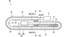
- FIG. 1 is a plan view showing a wiring member 10 according to the embodiment.
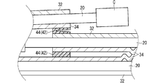
- FIG. 2 is a schematic sectional view taken along the line II-II of FIG.
- FIG. 3 is a schematic sectional view taken along line III-III in FIG.
- the left side of the drawing shows the state before the wiring body 12 is bent, and the right side of the drawing shows the state after the wiring body 12 is bent.
- the wiring member 10 includes a wiring body 12 and a temporary fastening portion 40 that maintains the bent state of the wiring body 12.
- the wiring member 10 is in a packaging form of the wiring body 12.
- the wiring body 12 is a member mounted on a vehicle for supplying electric power to each device of the vehicle and transmitting and receiving signals.
- the wiring body 12 includes a linear transmission member 20 and a base member 30 to which the linear transmission member 20 is fixed.
- the linear transmission member 20 may be a linear member that transmits electricity or light.
- the linear transmission member 20 may be a general electric wire having a core wire and a coating around the core wire, or may be a shield wire, a twist wire, an enamel wire, a nichrome wire, a bare wire, an optical fiber, or the like. Good.
- the linear transmission member 20 that transmits electricity various signal lines and various power lines may be used.
- the linear transmission member 20 that transmits electricity may be used as an antenna, a coil, or the like that sends or receives a signal or power to or from a space.
- the linear transmission member 20 may be a single linear object, or a composite of a plurality of linear objects (twisted wire, a cable in which a plurality of linear objects are assembled and covered with a sheath, etc.). ).
- terminals, connectors C, etc. are provided as appropriate according to the connection form between the linear transmission member 20 and the mating member.
- the linear transmission member 20 includes a transmission line body 22 that transmits electricity or light, and a coating 24 that covers the transmission line body 22.
- the linear transmission member 20 is a general electric wire
- the transmission line main body 22 is a core wire
- the coating 24 is an insulating coating.
- a plurality of linear transmission members 20 having the same diameter and structure are arranged on one sheet member 32, but the diameters and structures of the plurality of linear transmission members 20 are set as appropriate.
- the linear transmission members 20 having different diameters and structures may be arranged on the same sheet member 32.
- the base member 30 is a member that holds the linear transmission member 20 in a two-dimensionally positioned state.
- the base member 30 includes a sheet member 32 and a cover 34.
- the linear transmission member 20 is arranged on one main surface of the sheet member 32.
- the sheet member 32 holds the plurality of linear transmission members 20 in a line.
- the sheet member 32 may be a member having a degree of rigidity that is curved and can hold the plurality of linear transmission members 20 in a planarly positioned state, or may be a plurality of linear members that are kept flat. It may be a member having rigidity enough to hold the transmission member 20 in a two-dimensionally positioned state.
- the sheet member 32 may have a three-dimensionally shaped portion such that a wall is partially provided upright. Here, the sheet member 32 will be described as a bendable member.
- the material forming the sheet member 32 is not particularly limited, but the sheet member 32 is formed of a material containing a resin such as PVC (polyvinyl chloride), PET (polyethylene terephthalate), and PP (polypropylene). ..
- the sheet member 32 may be a fibrous material having fibers such as a non-woven fabric, a woven fabric, or a knitted fabric, or may be a non-fibrous material.
- the non-fibrous material may be a solid sheet material with the inside uniformly buried, or a foamed body obtained by foaming and molding a resin.
- the sheet member 32 may include a material such as metal.
- the sheet member 32 may have a single layer or a plurality of layers. When a plurality of layers are laminated, for example, a resin layer and a resin layer may be laminated. Further, for example, it is conceivable that the resin layer and the metal layer are laminated. Further, the sheet member 32 may be one in which a non-fibrous material layer and a non-fibrous material layer are stacked, or one in which a non-fibrous material layer and a fibrous material layer are stacked, or a fiber. The material layer and the fiber material layer may be stacked.
- the linear transmission member 20 is fixed to the sheet member 32.
- the linear transmission member 20 is fixed to the sheet member 32 in a state of being arranged along a predetermined path on the main surface of the sheet member 32.
- the sheet member 32 is formed in a strip shape extending along the path of the linear transmission member 20.
- the path of the linear transmission member 20 on the sheet member 32 may be set appropriately, and the linear transmission member 20 may be linearly arranged on the sheet member 32, or may be bent. May be.
- the sheet member 32 may also be bent.
- the plurality of linear transmission members 20 may be arranged on different paths so as to branch or intersect on the sheet member 32. In this case, the sheet member 32 may also be formed so as to branch or intersect.
- a plurality of linear transmission members 20 are arranged in an H shape while branching in the middle.
- the sheet member 32 is formed in an H shape along the paths of the plurality of linear transmission members 20.
- the linear transmission member 20 and the sheet member 32 are fixed.
- the contact part may be fixed, the non-contact part may be fixed, or both may be used in combination.
- the contact portion fixing means that the portions where the linear transmission member 20 and the sheet member 32 are in contact with each other are fixed to each other.
- the non-contact part fixing is a fixing mode that is not the contact part fixing. For example, a sewing thread, another sheet material, an adhesive tape, or the like presses the linear transmission member 20 toward the sheet member 32, or a sewing thread, another sheet material, an adhesive tape, or the like is used for the linear transmission member 20 and the sheet member.
- the linear transmission member 20 and the sheet member 32 are sandwiched between the linear transmission member 20 and the sheet member 32, and the linear transmission member 20 and the sheet member 32 are maintained in a fixed state.
- the linear transmission member 20 and the sheet member 32 are in the state of a contact site fixation.
- the respective descriptions regarding the fixing of the contact portion can be applied to the fixing of the non-contact portion as long as the configuration is not applicable.
- the form of fixing the contact portion may be indirect fixing, direct fixing, or both may be used together in different areas.
- the term “indirect fixing” means that the linear transmission member 20 and the sheet member 32 are indirectly fixed to each other through an intervening member such as an adhesive, an adhesive, a double-sided adhesive tape, or a fastener provided between them.
- the direct fixing means that the linear transmission member 20 and the sheet member 32 are directly fixed to each other without an adhesive or the like provided separately.
- the direct fixing for example, it is conceivable that the resin contained in at least one of the linear transmission member 20 and the sheet member 32 is melted and fixed to be stuck.
- the linear transmission member 20 and the sheet member 32 will be described as being directly fixed.
- Each description of the direct fixation is also applicable to the indirect fixation, unless the configuration is not applicable.
- the resin When forming such a directly fixed state, the resin may be melted by heat or may be melted by a solvent, for example. That is, the state of direct fixation may be a state of direct fixation by heat or a state of direct fixation by a solvent. Preferably, it is in a state of being directly fixed by heat.
- the means for directly forming the fixed state is not particularly limited, and various means including known means such as welding, fusing and welding can be used.
- various welding means such as ultrasonic welding, heating/pressurizing welding, hot air welding, and high frequency welding can be adopted.
- the directly fixed state is formed by these means, the linear transmission member 20 and the sheet member 32 are brought into the directly fixed state by the means.
- the directly fixed state is formed by ultrasonic welding, the linear transmission member 20 and the sheet member 32 are directly fixed by ultrasonic welding.
- a portion in which a state of being directly fixed by heat is formed by welding is a welded portion, and among these, a fixed portion by ultrasonic welding is an ultrasonic welded portion, and heat pressure welding is performed.
- the fixed portion by means of may be referred to as a heating and pressure welding portion or the like.
- both the resin contained in the coating 24 of the linear transmission member 20 and the resin contained in the sheet member 32 may be melted. In this case, both resins may be mixed and a clear interface may not be formed. In particular, when the coating 24 of the linear transmission member 20 and the sheet member 32 contain a resin such as the same resin material that is easily compatible with each other, both resins may be mixed and a clear interface may not be formed.
- the cover 34 is fixed to the sheet member 32.
- the cover 34 covers the linear transmission member 20 from the side opposite to the sheet member 32.
- the cover 34 is not fixed to the linear transmission member 20, but may be fixed.
- the fixing mode between the sheet member 32 and the cover 34 in the example shown in FIG. 3, indirect fixing using an inclusion 36 such as an adhesive is shown.
- the fixing mode of the sheet member 32 and the cover 34 is not limited to the indirect fixing, and various fixing modes described in the fixing mode of the sheet member 32 and the linear transmission member 20 can be used.
- the same sheet-shaped member may be used for the sheet member 32 and the cover 34, or different sheet-shaped members may be used.
- different sheet-shaped members are used for the sheet member 32 and the cover 34.
- the sheet-shaped member used for the sheet member 32 is more suitable for fixing to the linear transmission member 20 than the sheet-shaped member used for the cover 34.
- the sheet-shaped member used for the cover 34 has higher rigidity and excellent shape retention than the sheet-shaped member used for the sheet member 32.
- the sheet member 32 includes a first layer formed of the same material as the coating 24 of the linear transmission member 20 in the form of a solid sheet and fixed with electric wires, and a second layer formed of non-woven fabric and overlapping the first layer.
- the cover 34 is a member formed of nylon or the like into a solid sheet.
- the cover 34 is formed so as to have rigidity that is difficult to bend, for example.
- the wiring member 10 is preferably provided with an easy-to-bend portion that is easily bent.
- the easy-to-bend portion 16 is a portion in which the cover 34 is provided with a bellows structure portion 35 in which peaks and valleys are alternately continuous.
- the easy-to-bend portion 17 is a portion where the cover 34 is not partially provided. Particularly here, the easy-to-bend portion 17 is a portion where the cover 34 is provided with a space.
- the wiring body 12 is bent at the easy-to-bend portions 16 and 17, respectively.
- the temporary fastening portion 40 maintains the bent state of the wiring body 12 in a state where the wiring body 12 is bent at the intermediate portion in the extending direction of the linear transmission member 20.
- the temporary fastening portion 40 holds the portion of the wiring body 12 in which the wiring body 12 is bent by fastening a portion where the first portion and the second portion extending from the bent portion to the opposite side from each other overlap each other.
- the temporary fastening portion 40 is formed so that the state in which the first portion and the second portion are fastened can be canceled by the relative separation movement of the first portion and the second portion.
- the direction of the relative separation movement of the first portion and the second portion is not particularly limited. For example, it may be movement in the overlapping direction of the first portion and the second portion (vertical direction on the paper surface of FIG. 2), or may be a direction orthogonal to this (horizontal direction on the paper surface of FIG. 2 or with respect to the paper surface of FIG. 2). It may be a movement in the normal direction).
- the temporary fastening section 40 is only required to be able to temporarily fasten the first portion and the second portion, and the configuration thereof is not particularly limited.
- an adhesive portion 42 is provided as the temporary fastening portion 40.
- the adhesive part 42 can be regarded as an example of an indirect fixing part.
- the adhesive part 42 has an inclusion 44 which is interposed between the first part and the second part and which is adhered to the first part and the second part.
- the inclusions 44 may be an adhesive or an adhesive other than the adhesive.
- the adhesive other than the pressure-sensitive adhesive hot melt, thermosetting adhesive, moisture curable adhesive, two-component curable adhesive, etc. can be used. When an adhesive other than the adhesive is used, it cannot be re-adhered in the peeled state as it is.
- an indirect fixing part other than the adhesive part 42 may be provided.
- a surface fastener may be provided as an indirect fixing portion other than the adhesive portion 42.
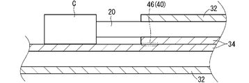
- FIG. 4 is a schematic sectional view showing a modified example of the temporary fastening portion 40.
- a direct fixing portion 46 is provided as the temporary fastening portion 40.
- the direct fixing portion 46 is formed by directly fixing the base member 30 in the first portion and the base member 30 in the second portion. Particularly, in the example shown in FIG. 4, the direct fixing portion 46 is formed by directly fixing the cover 34 in the first portion and the cover 34 in the second portion.
- the direct fixing here is the same as the direct fixing described in the fixing mode of the sheet member 32 and the linear transmission member 20.
- the temporary fastening portions 40a and 40b maintain the state in which the wiring body 12 is bent so as to be tripled.
- the wiring body 12 has a base portion 13, a first bent portion 14, and a second bent portion 15.
- the first bent portion 14 is a portion that extends from one end of the base portion 13 and is bent so as to overlap the base portion 13.
- the second bent portion 15 is a portion that extends from the other end of the base portion 13 and is bent so as to overlap the first bent portion 14.
- the temporary fastening portion 40 a fastens the base portion 13 and the first bent portion 14.
- the temporary fastening portion 40b fastens the first bent portion 14 and the second bent portion 15.
- the base portion 13 and the first bent portion 14 are the first portion and the second portion. Further, in the portion related to the temporary fastening portion 40b, the first bent portion 14 and the second bent portion 15 are the first portion and the second portion.
- the wiring member 10 includes a portion in which the wiring body 12 is folded so as to be tripled.
- the wiring member may include a portion in which the wiring body 12 is bent so as to be doubled, or may include a portion in which the wiring body 12 is bent so as to be overlapped four or more times.
- the wiring member may include only a portion in which the wiring body 12 is folded so as to be doubly overlapped.
- the temporary fastening portion 40 may fasten the sheet members 32 to each other, fasten the covers 34 to each other, or the sheet member 32 and the cover 34. May be stopped.
- the temporary fastening portion 40a fastens the covers 34 to each other.
- the temporary fastening portion 40b fastens the sheet member 32 and the cover 34.
- the plurality of temporary fastening portions 40 may have the same temporary fastening mode or different temporary fastening modes.
- the temporary fastening portions 40a and 40b are both the adhesive portions 42, but one may be the direct fixing portion 46 or the like.
- the materials forming the plurality of temporary fastening portions 40 may be the same or different.
- the combination of the members to which the temporary fastening portion 40a adheres differs from the combination of the members to which the temporary fastening portion 40b adheres.
- the temporary fastening portions 40a and 40b may be made of the same material, or may be made of different materials so as to suit the combination of the respective materials.
- the temporary fastening portion 40 is preferably formed so as to be able to release the state in which the first portion and the second portion are fastened with a force weaker than the holding force between the sheet member 32 and the linear transmission member 20. This can prevent the sheet member 32 and the linear transmission member 20 from peeling off when the temporary fastening state by the temporary fastening portion 40 is canceled.
- the temporary fastening portion 40b that temporarily fastens the sheet member 32 can eliminate the state in which the first portion and the second portion are fastened with a force weaker than the holding force between the sheet member 32 and the linear transmission member 20. It should be formed.
- the cover 34 is fastened to the temporary fastening portion 40 in at least one of the first portion and the second portion.
- the temporary fastening portion 40a the temporary fastening portion 40 fastens the cover 34 at both the base portion 13 and the first bent portion 14, that is, at both the first portion and the second portion.
- the temporary fastening portion 40b the temporary fastening portion 40 fastens the cover 34 at the second bent portion 15, that is, at one of the first portion and the second portion.
- the temporary fastening portion 40 eliminates the state in which the first portion and the second portion are fastened with a force weaker than the holding force between the sheet member 32 and the cover 34. It is preferable that it is formed to be possible. As a result, it is possible to prevent the sheet member 32 and the cover 34 from peeling off when the temporary fastening state by the temporary fastening portion 40 is canceled.
- the holding force of the temporary fastening portion 40 can be weakened by using, for example, an inclusion 44 having a weak adhesive force.
- the holding force of the temporary fastening portion 40 can be weakened by reducing the energy applied when forming the direct fixing portion 46. More specifically, in the case of the direct fixing portion 46 by ultrasonic welding, the energy applied when the direct fixing portion 46 is formed by reducing the amplitude, reducing the pressure, or shortening the welding time. Can be made smaller.
- the holding force may change depending on the combination of the materials.
- the fixing portion 46 may be directly employed in the temporary fastening portion 40b that fastens the sheet member 32 and the cover 34, and the adhesive portion 42 may be employed in the temporary fastening portion 40a that fastens the covers 34 to each other.
- FIG. 5 is an explanatory diagram showing how the wiring member 10 having the adhesive portion 42 is developed. Note that in the example shown in FIG. 5, the wiring member 10 is expanded by relatively moving away from each other in the direction in which the first portion and the second portion overlap. The same applies to the example shown in FIG. 6 described later.
- the first state is a state in which the interface between the first portion or the second portion and the adhesive portion 42 is peeled off.
- the second state is a state in which a part or all of one of the first portion and the second portion is attached to the other.
- delamination occurs between a portion that forms an interface with the adhesive portion 42 inside one of the first portion and the second portion and a portion around the delamination, and a part is generated. Is attached to the other of the first portion and the second portion.
- the third state is a state in which delamination occurs between the portion on the first portion side and the portion on the second portion side inside the adhesive portion 42. In the example shown in FIG. 5, this third state is shown.
- the wiring member 10 having the adhesive portion 42 is expanded to the first state. When it becomes, it may have a re-adhesive property. Further, in the case of the adhesive portion 42 using the adhesive, the portion where the wiring member 10 having the adhesive portion 42 is expanded to the second or third state has no re-adhesive property or the adhesive property is deteriorated. For example, a portion in the first state where the mating member does not adhere to the adhesive surface of the adhesive portion 42 formed by the adhesive may be in a state of re-adhesiveness.
- the trace of the adhesive portion 42 has re-adhesiveness at least as it is. Disappear.
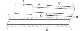
- FIG. 6 is an explanatory diagram showing how the wiring member 10 having the direct fixing portion 46 is developed.
- the trace 50 thereof is considered to be in either the first state or the second state. That is, the first state is a state in which the interface between the first portion and the second portion of the direct fixing portion 46 is peeled off. The first state can occur, for example, when only one resin is melted between different kinds of materials to directly form the fixing portion 46.
- the second state is a state in which a part or all of one of the first portion and the second portion is attached to the other. The second state may occur, for example, when both the resins are melted between the same type of materials and the fixing portion 46 is directly formed.
- the second state delamination occurs between the portion including the interface of the direct fixing portion 46 and the surrounding portion inside one of the first portion and the second portion, and a part of the first portion is the first portion.
- the state of sticking to the other of the part or the second part may be mentioned. In the example shown in FIG. 6, this second state is shown.
- the trace 50 of the direct fixing portion 46 has re-adhesiveness at least as it is, regardless of whether the wiring member 10 is in the first state or the second state. It will disappear.
- the trace of the temporary fastening portion 40 does not have re-adhesiveness as it is.
- FIG. 7 is a schematic cross-sectional view showing the wiring member arrangement structure 100 according to the embodiment.
- the wiring member 10 is unfolded and placed on the placement target 80 to form the wiring member placement structure 100.
- the arrangement target 80 is not particularly limited.
- the arrangement target 80 is each part of the vehicle such as the roof, floor, instrument panel, and reinforcement of the vehicle.
- the wiring member 10 after deployment is referred to as a wiring member 10A.
- the state where the temporary fastening portion 40 fastens the first portion and the second portion is canceled and the first portion and the second portion are in a developed state. It is conceivable that when the wiring member 10 is developed and the temporary fastening portion 40 is eliminated, the trace 50 of the temporary fastening portion 40 remains on the wiring member 10A after the development. In the wiring member arrangement structure 100, the trace 50 of the temporary fastening portion 40 is not used for fixing to the arrangement target 80.
- the trace 50 of the temporary fastening portion 40 cannot be joined again without being processed as it is.
- the temporary fastening portion 40 that does not have re-adhesiveness as it is is adopted, and the wiring member 10 having the temporary fastening portion 40 is developed. As a result, the trace 50 of the temporary fastening portion 40 cannot be joined again without being processed.
- the wiring body 12 is bent such that the bent portions 14 and 15 are overlapped on the surface of the base 13 opposite to the surface facing the arrangement target 80 side. Therefore, in the wiring member arrangement structure 100, the trace 50a of the temporary fastening portion 40a is not located on the arrangement target 80 side.
- the temporary fastening portion 40b fastens the first bent portion 14 and the second bent portion 15. At this time, when the trace 50b of the temporary fastening portion 40b remains on the first bent portion 14, the trace 50b of the temporary fastening portion 40b is located on the side of the arrangement target 80, but the trace 50b of the temporary fastening portion 40b is the first.
- the trace 50b of the temporary fastening portion 40b is not located on the arrangement target 80 side.
- the trace 50 of the temporary fastening portion 40 adheres to an unintended location on the placement target 80 and interferes with the work of arranging the wiring member 10. Can be suppressed.
- the temporary fastening portion 40 is formed so that the state in which the first portion and the second portion are fastened by the relative separation movement of the first portion and the second portion can be eliminated. Therefore, the temporary fixing state by the temporary fixing portion 40 can be canceled by the unfolding operation. As a result, the wiring member 10 can be easily maintained in the bent form.
- the temporary fastening portion 40 when the temporary fastening portion 40 includes the adhesive portion 42, the temporary fastening portion 40 can be easily formed by the inclusion 44 such as an adhesive or a double-sided adhesive tape. Further, when the temporary fastening portion 40 directly includes the fixing portion 46, it is not necessary to provide another member as the temporary fastening portion 40.
- the temporary fastening portion 40 is formed so as to be able to cancel the state in which the first portion and the second portion are fastened with a force weaker than the holding force between the sheet member 32 and the linear transmission member 20, and thus the temporary fastening portion 40. It is possible to prevent the linear transmission member 20 from peeling off from the sheet member 32 when the temporary fastening state due to is canceled.
- the temporary fastening portion 40 fastens the cover 34 portion to which the linear transmission member 20 is not fixed. This can prevent the linear transmission member 20 from peeling off from the sheet member 32 when the temporary fastening state by the temporary fastening portion 40 is canceled.
- the temporary fastening portion 40 is formed so as to be able to cancel the state in which the first portion and the second portion are fastened with a force weaker than the holding force between the sheet member 32 and the cover 34, the temporary fastening portion 40 is temporarily fastened. It is possible to prevent the cover 34 from coming off the sheet member 32 when the state is resolved.
- FIG. 8 is a schematic cross-sectional view showing a modified example of the wiring member 10.
- the base member 130 may not include the cover 34 as in the wiring member 110 shown in FIG. 8.
- the temporary fastening portion 40d fastens the sheet members 32 to each other.
- the temporary fastening portion 40 has been described so far as fastening the portion of the base member 30 that overlaps the linear transmission member 20, this is not an essential configuration. As in the example shown in FIG. 8, the temporary fastening portion 40d may fasten a portion that does not overlap the linear transmission member 20 (a lateral portion of the linear transmission member 20).
- the wiring body 112 is bent so that the linear transmission members 20 face each other. From another perspective, the wiring body 112 is bent so that the surfaces of the sheet member 32 to which the linear transmission member 20 is fixed face each other, but this is not an essential configuration.
- the wiring body may be bent such that the surfaces of the sheet member 32 to which the linear transmission member 20 is not fixed face each other.
- the wiring body may be bent such that the surface of the sheet member 32 to which the linear transmission member 20 is fixed and the surface of the sheet member 32 to which the linear transmission member 20 is not fixed face each other.
- the linear transmission member 20 is described as being fixed on the sheet member 32 as the base member 30, but this is not an essential configuration.
- the linear conductor may be fixed inside the base member.
- a so-called FFC flexible flat cable formed by sandwiching a plurality of linear conductors between two films or extruding a resin material around the plurality of linear conductors is used. It may be.
- Wiring member 12 Wiring body 13 Base portion 14, 15 Bending portion 16, 17 Bending easy portion 20 Linear transmission member 30 Base member 32 Sheet member 34 Cover 40 Temporary fastening portion 42 Adhesive portion 44 Inclusions 46 Direct fixing portion 50 Traces 80 Arrangement target 100 Arrangement structure of wiring members
Landscapes
- Engineering & Computer Science (AREA)
- Architecture (AREA)
- Civil Engineering (AREA)
- Structural Engineering (AREA)
- Details Of Indoor Wiring (AREA)
- Insulated Conductors (AREA)
Abstract
Description
以下、実施形態に係る配線部材について説明する。図1は、実施形態に係る配線部材10を示す平面図である。図2は、図1のII-II線に沿って切断した概略断面図である。図3は、図2のIII-III線に沿って切断した概略断面図である。なお、図1に示す配線部材10において、紙面左側部分は配線体12が折曲げられる前の状態を示し、紙面右側は配線体12が折曲げられた後の状態を示している。
図5は、接着部42を有する配線部材10が展開される様子を示す説明図である。なお図5に示す例では、第1部分及び第2部分が重なる方向に相対的に離間移動して、配線部材10が展開されている。後述する図6に示す例でも同様である。
図7は、実施形態に係る配線部材の配設構造100を示す概略断面図である。
図8は、配線部材10の変形例を示す概略断面図である。
12 配線体
13 基部
14、15 折曲げ部
16、17 折曲げ容易部
20 線状伝送部材
30 ベース部材
32 シート部材
34 カバー
40 仮留め部
42 接着部
44 介在物
46 直接固定部
50 痕跡
80 配設対象
100 配線部材の配設構造
Claims (7)
- 線状伝送部材と、前記線状伝送部材が固定されたベース部材と、を含む配線体と、
前記配線体が前記線状伝送部材の延在方向中間部で折曲げられた状態で、前記配線体において折曲げ箇所から相互に反対側に延びる第1部分及び第2部分が重なる部分を留めて前記配線体の折曲げ状態を維持しているとともに、前記第1部分及び前記第2部分の相対的な離間移動によって前記第1部分及び前記第2部分を留めた状態を解消可能に形成されている仮留め部と、
を備える、配線部材。 - 請求項1に記載の配線部材であって、
前記仮留め部は、前記第1部分及び前記第2部分の間に介在し、前記第1部分及び前記第2部分に接着された接着部を含む、配線部材。 - 請求項1又は請求項2に記載の配線部材であって、
前記仮留め部は、前記第1部分における前記ベース部材と、前記第2部分における前記ベース部材とが直接固定された直接固定部を含む、配線部材。 - 請求項1から請求項3のいずれか1項に記載の配線部材であって、
前記ベース部材として、主面上に前記線状伝送部材が固定されたシート部材を含み、
前記仮留め部は、前記シート部材と前記線状伝送部材との保持力よりも弱い力で前記第1部分及び前記第2部分を留めた状態を解消可能に形成されている、配線部材。 - 請求項1から請求項4のいずれか1項に記載の配線部材であって、
前記ベース部材として、主面上に前記線状伝送部材が固定されたシート部材と、前記シート部材に固定され、前記シート部材とは反対側から前記線状伝送部材を覆うカバーとを含み、
前記第1部分及び前記第2部分の少なくとも一方において、前記仮留め部は、前記カバーを留めている、配線部材。 - 請求項5に記載の配線部材であって、
前記仮留め部は、前記シート部材と前記カバーとの保持力よりも弱い力で前記第1部分及び前記第2部分を留めた状態を解消可能に形成されている、配線部材。 - 請求項1から請求項6のいずれか1項に記載の配線部材と、
前記仮留め部が前記第1部分及び前記第2部分を留めた状態が解消されて前記第1部分及び前記第2部分が展開された状態で前記配線部材が配設されている配設対象と、
を備える、配線部材の配設構造。
Priority Applications (5)
| Application Number | Priority Date | Filing Date | Title |
|---|---|---|---|
| PCT/JP2019/003447 WO2020157929A1 (ja) | 2019-01-31 | 2019-01-31 | 配線部材及び配線部材の配設構造 |
| DE112019006785.0T DE112019006785B4 (de) | 2019-01-31 | 2019-01-31 | Verdrahtungselement und Anordnungsstruktur eines Verdrahtungselements |
| US17/423,038 US11735336B2 (en) | 2019-01-31 | 2019-01-31 | Wiring member and arrangement structure of wiring member |
| CN201980088929.5A CN113692626B (zh) | 2019-01-31 | 2019-01-31 | 布线部件及布线部件的配设构造 |
| JP2020569290A JP7168006B2 (ja) | 2019-01-31 | 2019-01-31 | 配線部材及び配線部材の配設構造 |
Applications Claiming Priority (1)
| Application Number | Priority Date | Filing Date | Title |
|---|---|---|---|
| PCT/JP2019/003447 WO2020157929A1 (ja) | 2019-01-31 | 2019-01-31 | 配線部材及び配線部材の配設構造 |
Publications (1)
| Publication Number | Publication Date |
|---|---|
| WO2020157929A1 true WO2020157929A1 (ja) | 2020-08-06 |
Family
ID=71842406
Family Applications (1)
| Application Number | Title | Priority Date | Filing Date |
|---|---|---|---|
| PCT/JP2019/003447 Ceased WO2020157929A1 (ja) | 2019-01-31 | 2019-01-31 | 配線部材及び配線部材の配設構造 |
Country Status (5)
| Country | Link |
|---|---|
| US (1) | US11735336B2 (ja) |
| JP (1) | JP7168006B2 (ja) |
| CN (1) | CN113692626B (ja) |
| DE (1) | DE112019006785B4 (ja) |
| WO (1) | WO2020157929A1 (ja) |
Cited By (1)
| Publication number | Priority date | Publication date | Assignee | Title |
|---|---|---|---|---|
| WO2025182670A1 (ja) * | 2024-03-01 | 2025-09-04 | 株式会社オートネットワーク技術研究所 | 配線部材及び配線部材の製造方法 |
Families Citing this family (4)
| Publication number | Priority date | Publication date | Assignee | Title |
|---|---|---|---|---|
| JP7140052B2 (ja) * | 2019-05-31 | 2022-09-21 | 株式会社オートネットワーク技術研究所 | 配線部材 |
| JP7358935B2 (ja) * | 2019-11-21 | 2023-10-11 | 株式会社オートネットワーク技術研究所 | 配線部材 |
| JP7600900B2 (ja) * | 2021-06-30 | 2024-12-17 | 株式会社オートネットワーク技術研究所 | 配線部材 |
| US12183483B2 (en) * | 2021-12-10 | 2024-12-31 | W.L. Gore & Associates Gmbh | Cable unit |
Citations (2)
| Publication number | Priority date | Publication date | Assignee | Title |
|---|---|---|---|---|
| JP2006222059A (ja) * | 2005-01-17 | 2006-08-24 | Junkosha Co Ltd | フラットケーブル |
| JP2018190696A (ja) * | 2017-05-10 | 2018-11-29 | 株式会社オートネットワーク技術研究所 | 配線モジュール、複合配線モジュール及び配線モジュール付固定対象部材 |
Family Cites Families (11)
| Publication number | Priority date | Publication date | Assignee | Title |
|---|---|---|---|---|
| GB1458214A (en) * | 1973-04-04 | 1976-12-08 | Rists Wires & Cables Ltd | Wiring harness disc player |
| US4065199A (en) * | 1977-02-11 | 1977-12-27 | Methode Electronics, Inc. | Flat cable wiring harness and method of producing same |
| GB8827681D0 (en) * | 1988-11-25 | 1988-12-29 | Gaddis F | Bubble/water agitation device |
| JP2002033554A (ja) | 2000-07-17 | 2002-01-31 | Nippon Avionics Co Ltd | 180度折り曲げ可能なフレキシブルプリント配線板 |
| JP3794556B2 (ja) * | 2001-12-03 | 2006-07-05 | 古河電気工業株式会社 | フラット配線材を積層した積層配線材 |
| WO2006112098A1 (ja) | 2005-03-31 | 2006-10-26 | Junkosha Inc. | フラットケーブル |
| US20090314515A1 (en) * | 2008-06-20 | 2009-12-24 | Bevirt Joeben | Folding cord with rigid sections and magnets |
| JP6048472B2 (ja) | 2014-10-27 | 2016-12-21 | 株式会社オートネットワーク技術研究所 | ワイヤーハーネスモジュール |
| CN204257244U (zh) | 2014-12-29 | 2015-04-08 | 安徽蒙特尔电缆集团有限公司 | 一种可弯折数字信号扁平电缆 |
| JP6497420B2 (ja) | 2017-02-23 | 2019-04-10 | 株式会社オートネットワーク技術研究所 | ワイヤーハーネス |
| CN109038042B (zh) | 2018-06-28 | 2020-08-28 | 江西立时科技股份有限公司 | 一种数据连接线 |
-
2019
- 2019-01-31 CN CN201980088929.5A patent/CN113692626B/zh active Active
- 2019-01-31 DE DE112019006785.0T patent/DE112019006785B4/de active Active
- 2019-01-31 JP JP2020569290A patent/JP7168006B2/ja active Active
- 2019-01-31 WO PCT/JP2019/003447 patent/WO2020157929A1/ja not_active Ceased
- 2019-01-31 US US17/423,038 patent/US11735336B2/en active Active
Patent Citations (2)
| Publication number | Priority date | Publication date | Assignee | Title |
|---|---|---|---|---|
| JP2006222059A (ja) * | 2005-01-17 | 2006-08-24 | Junkosha Co Ltd | フラットケーブル |
| JP2018190696A (ja) * | 2017-05-10 | 2018-11-29 | 株式会社オートネットワーク技術研究所 | 配線モジュール、複合配線モジュール及び配線モジュール付固定対象部材 |
Non-Patent Citations (1)
| Title |
|---|
| "Lead Wire", JIPII JOURNAL OF TECHNICAL DISCLOSURE NO. 94-9311, 2 May 1994 (1994-05-02), pages 1 * |
Cited By (1)
| Publication number | Priority date | Publication date | Assignee | Title |
|---|---|---|---|---|
| WO2025182670A1 (ja) * | 2024-03-01 | 2025-09-04 | 株式会社オートネットワーク技術研究所 | 配線部材及び配線部材の製造方法 |
Also Published As
| Publication number | Publication date |
|---|---|
| US20220076862A1 (en) | 2022-03-10 |
| JP7168006B2 (ja) | 2022-11-09 |
| CN113692626A (zh) | 2021-11-23 |
| US11735336B2 (en) | 2023-08-22 |
| DE112019006785T5 (de) | 2021-12-30 |
| CN113692626B (zh) | 2023-09-15 |
| DE112019006785B4 (de) | 2025-12-31 |
| JPWO2020157929A1 (ja) | 2020-08-06 |
Similar Documents
| Publication | Publication Date | Title |
|---|---|---|
| JP7168006B2 (ja) | 配線部材及び配線部材の配設構造 | |
| JP2018190696A (ja) | 配線モジュール、複合配線モジュール及び配線モジュール付固定対象部材 | |
| CN113519032B (zh) | 带有固定构件的布线构件及布线构件的固定构造 | |
| US20240120130A1 (en) | Wiring member-equipped adherend | |
| JP7658197B2 (ja) | 配線部材 | |
| US20220140587A1 (en) | Wiring member with fixing member and fixing structure of wiring member | |
| JP7184020B2 (ja) | 配線部材 | |
| JP7424177B2 (ja) | 配線部材 | |
| JP7314793B2 (ja) | 配線部材 | |
| WO2018207641A1 (ja) | 配線モジュール、複合配線モジュール及び配線モジュール付固定対象部材 | |
| US20220407296A1 (en) | Wiring member | |
| CN113508440B (zh) | 带固定构件的布线构件及带固定构件的布线构件的制造方法 | |
| JP7419709B2 (ja) | 固定部材付き配線部材 | |
| JP7184019B2 (ja) | 配線部材 | |
| CN113614856B (zh) | 配线部件 | |
| US12497544B2 (en) | Fusion sheet and wiring member | |
| JP7574873B2 (ja) | 配線部材 | |
| JP7419710B2 (ja) | 固定部材付き配線部材 | |
| WO2025142423A1 (ja) | 配線部材及び配線部材の製造方法 | |
| JP2020145196A (ja) | 固定部材付き配線部材 |
Legal Events
| Date | Code | Title | Description |
|---|---|---|---|
| 121 | Ep: the epo has been informed by wipo that ep was designated in this application |
Ref document number: 19912219 Country of ref document: EP Kind code of ref document: A1 |
|
| ENP | Entry into the national phase |
Ref document number: 2020569290 Country of ref document: JP Kind code of ref document: A |
|
| WWE | Wipo information: entry into national phase |
Ref document number: 112019006785 Country of ref document: DE |
|
| WWP | Wipo information: published in national office |
Ref document number: 112019006785 Country of ref document: DE |
|
| 122 | Ep: pct application non-entry in european phase |
Ref document number: 19912219 Country of ref document: EP Kind code of ref document: A1 |
|
| WWG | Wipo information: grant in national office |
Ref document number: 112019006785 Country of ref document: DE |