WO2020155348A1 - 一种超声波信号调整方法、装置及超声阵列 - Google Patents
一种超声波信号调整方法、装置及超声阵列 Download PDFInfo
- Publication number
- WO2020155348A1 WO2020155348A1 PCT/CN2019/079812 CN2019079812W WO2020155348A1 WO 2020155348 A1 WO2020155348 A1 WO 2020155348A1 CN 2019079812 W CN2019079812 W CN 2019079812W WO 2020155348 A1 WO2020155348 A1 WO 2020155348A1
- Authority
- WO
- WIPO (PCT)
- Prior art keywords
- array
- ultrasonic
- amplitude modulation
- columnar structure
- ultrasonic signal
- Prior art date
- Legal status (The legal status is an assumption and is not a legal conclusion. Google has not performed a legal analysis and makes no representation as to the accuracy of the status listed.)
- Ceased
Links
Images






Classifications
-
- A—HUMAN NECESSITIES
- A61—MEDICAL OR VETERINARY SCIENCE; HYGIENE
- A61B—DIAGNOSIS; SURGERY; IDENTIFICATION
- A61B8/00—Diagnosis using ultrasonic, sonic or infrasonic waves
- A61B8/44—Constructional features of the ultrasonic, sonic or infrasonic diagnostic device
- A61B8/4483—Constructional features of the ultrasonic, sonic or infrasonic diagnostic device characterised by features of the ultrasound transducer
-
- A—HUMAN NECESSITIES
- A61—MEDICAL OR VETERINARY SCIENCE; HYGIENE
- A61B—DIAGNOSIS; SURGERY; IDENTIFICATION
- A61B8/00—Diagnosis using ultrasonic, sonic or infrasonic waves
- A61B8/52—Devices using data or image processing specially adapted for diagnosis using ultrasonic, sonic or infrasonic waves
- A61B8/5269—Devices using data or image processing specially adapted for diagnosis using ultrasonic, sonic or infrasonic waves involving detection or reduction of artifacts
Definitions
- the invention relates to the technical field of ultrasonic transducers, in particular to an ultrasonic signal adjustment method, device and ultrasonic array.
- the ultrasonic transducer uses the electronic signal delay to adjust the ultrasonic beam generated by the ultrasonic array, but it produces unnecessary in the diffracted sound field of the ultrasonic transducer.
- the diffraction grating lobes and side lobes are shown in Figure 1.
- the main diffracted lobes generated in the diffracted sound field of the ultrasonic transducer are used to act on the target area to achieve the effect of diagnosis and treatment, while the diffraction grating and side lobes generated on both sides of the diffracted main lobe are It will have a certain impact on non-target areas, which greatly limits the clinical application of ultrasound transducers in modern medicine.
- the embodiments of the present invention provide an ultrasonic signal adjustment method, device, and ultrasonic array, which can effectively suppress diffraction grating lobes and side lobes in the ultrasonic signal generated by the ultrasonic transducer.
- An ultrasonic signal adjustment method characterized in that the ultrasonic signal adjustment method is based on a cylindrical structure ultrasonic array, and the ultrasonic signal adjustment method includes:
- Each array element in the columnar structure ultrasonic array is in a planar and periodically distributed columnar arrangement structure, so The ultrasonic diffraction surface of the columnar structure ultrasonic array is a plane, and any adjacent array elements in the columnar structure ultrasonic array are arranged without intervals.
- the method before performing amplitude modulation on the ultrasonic signal generated by each element in the columnar structure ultrasonic array to obtain the amplitude-modulated ultrasonic signal, the method further includes:
- the magnitude of the amplitude modulation and the type of the amplitude modulation are set according to the diffraction sidelobes of the ultrasonic signal generated by each element in the columnar structure ultrasonic array.
- the process of performing amplitude modulation on the ultrasonic signal generated by each element in the columnar structure ultrasonic array includes:
- Gaussian amplitude modulation with a preset amplitude modulation magnitude is performed on the ultrasonic signal generated by each element in the columnar structure ultrasonic array.
- the process of performing Gaussian amplitude modulation on the ultrasonic signals generated by the elements in the columnar structure ultrasonic array includes:
- the Gaussian amplitude modulation function h(x) includes:
- x is the space coordinate of any point in the Gaussian amplitude modulation function
- p 0 is a constant
- ⁇ is the Gaussian amplitude modulation size parameter.
- the method before performing amplitude modulation on the ultrasonic signal generated by each element in the columnar structure ultrasonic array, the method further includes:
- the phase adjustment function for performing phase adjustment on the ultrasonic signal generated by each element in the columnar structure ultrasonic array includes:
- x and y represent the space coordinates of any point in the phase adjustment function
- p 0 is a constant
- I the phase size at the point in space (x, y).
- An ultrasonic signal adjustment device is based on a cylindrical structure ultrasonic array, and the ultrasonic signal adjustment device includes:
- the amplitude modulation module is used to perform amplitude modulation on the ultrasonic signal generated by each element in the cylindrical structure ultrasonic array to obtain an amplitude modulated ultrasonic signal.
- Each element in the cylindrical structure ultrasonic array is periodically distributed on a plane In the columnar arrangement structure, the ultrasonic diffraction surface of the columnar structure ultrasonic array is flat, and any adjacent array elements in the columnar structure ultrasonic array are arranged without intervals.
- it also includes:
- the amplitude modulation setting module is used to set the magnitude of the amplitude modulation and the type of the amplitude modulation according to the diffraction sidelobes of the ultrasonic signal generated by each element in the columnar structure ultrasonic array.
- the amplitude modulation module includes:
- the Gaussian amplitude modulation module is used to perform Gaussian amplitude modulation with a preset amplitude modulation level on the ultrasonic signals generated by each element in the columnar structure ultrasonic array.
- the Gaussian amplitude modulation module includes:
- the Gaussian amplitude modulation sub-module is used to apply different excitation signals to each element in the columnar structure ultrasonic array, and perform Gaussian amplitude modulation with a preset amplitude modulation level.
- the magnitude of the excitation signal applied by each array element is determined according to the Gaussian amplitude modulation function, and the Gaussian amplitude modulation function h(x) includes:
- x is the space coordinate of any point in the Gaussian amplitude modulation function
- p 0 is a constant
- ⁇ is the Gaussian amplitude modulation size parameter.
- it also includes:
- a phase adjustment module for performing phase adjustment on the ultrasonic signal generated by each element in the columnar structure ultrasonic array
- the phase adjustment function for performing phase adjustment on the ultrasonic signal generated by each element in the columnar structure ultrasonic array includes:
- x and y represent the space coordinates of any point in the phase adjustment function
- p 0 is a constant
- I the phase size at the point in space (x, y).
- An ultrasound array including:
- the ultrasonic array is in a columnar structure, each element in the ultrasonic array is in a columnar arrangement structure periodically distributed in a plane, the ultrasonic diffraction surface of the columnar structure ultrasonic array is a plane, and any phase in the columnar structure ultrasonic array
- the adjacent elements are arranged without intervals.
- an ultrasonic signal adjustment method is based on a cylindrical structure ultrasonic array.
- the ultrasonic signal adjustment method includes: The ultrasonic signal generated by each element in the array performs amplitude modulation to obtain the amplitude-modulated ultrasonic signal.
- Each element in the columnar structure ultrasonic array is in a cylindrical arrangement structure with a plane periodic distribution, and the diffraction of the columnar structure ultrasonic array The surface is a plane, and any adjacent array elements in the columnar structure ultrasonic array are arranged without intervals.
- each element in the columnar structure ultrasonic array is a columnar arrangement structure periodically distributed in a plane, the diffraction surface of the columnar structure ultrasonic array is flat, and the columnar structure Arbitrary adjacent array elements in the structured ultrasonic array are arranged without intervals, which can suppress the diffraction grating lobes in the ultrasonic signal, and then the ultrasonic signal can be suppressed by performing amplitude modulation on the ultrasonic signal generated by each element in the columnar structured ultrasonic array Diffraction sidelobes in.
- FIG. 1 is a schematic diagram of an ultrasonic beam of an ultrasonic transducer array provided by an embodiment of the present invention
- FIG. 2 is a schematic diagram of acoustic diffraction of a one-dimensional ultrasonic transducer array provided by an embodiment of the present invention
- Figure 3(a) is a schematic diagram of wavefront distribution of a transducer array with periodic point source distribution of limited length according to an embodiment of the present invention
- Fig. 3(b) is a schematic diagram of Fourier transform of a finite-length periodic point source array provided by an embodiment of the present invention
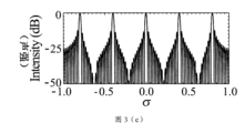
- FIG. 3(c) is a schematic diagram of a normalized sound intensity distribution of a finite-length periodic point source array provided by an embodiment of the present invention
- FIG. 5 is a flowchart of another ultrasonic signal adjustment method provided by an embodiment of the present invention.
- Figure 6(a) is a schematic diagram of wavefront distribution of a finite-length periodic line source array provided by an embodiment of the present invention
- 6(b) is a schematic diagram of Fourier transform of a finite-length periodic line source array provided by an embodiment of the present invention
- 6(c) is a schematic diagram of normalized sound intensity distribution under the condition that any adjacent array elements in a finite-length periodic line source array are arranged without intervals according to an embodiment of the present invention
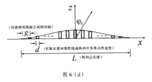
- Fig. 6(d) is a schematic diagram of wavefront distribution under the condition that arbitrary adjacent elements in a finite-length periodic line source array are arranged without intervals under amplitude modulation according to an embodiment of the present invention
- Fig. 6(e) is a schematic diagram of Fourier transform of a finite-length periodic line source array after Gaussian amplitude modulation according to an embodiment of the present invention
- 6(f) is a schematic diagram of a normalized sound intensity distribution of a finite-length periodic line source array after Gaussian amplitude modulation according to an embodiment of the present invention
- Fig. 7(a) is a schematic diagram of the diffraction sound intensity distribution of a finite-length periodic surface source array provided by an embodiment of the present invention
- FIG. 7(b) is a schematic diagram of the diffraction sound intensity distribution under the condition that any adjacent elements in the finite-length periodic surface source array are arranged without spacing according to an embodiment of the present invention
- FIG. 7(c) is a schematic diagram of the diffraction sound intensity distribution under the Gaussian amplitude modulation provided by an embodiment of the present invention, and any adjacent array elements in a finite-length periodic surface source array are arranged without intervals;
- FIG. 8 is a flowchart of another ultrasonic signal adjustment method provided by an embodiment of the present invention.
- Figure 9(a) is a schematic diagram of the amplitude distribution of each element of the transducer array under the condition of equal amplitude excitation provided by the embodiment of the present invention.
- FIG. 9(b) is a schematic diagram of the phase distribution of each element of the transducer array when the focus point is located at (0, 0, 40) mm according to an embodiment of the present invention.
- Figure 9(c) is a schematic diagram of the amplitude distribution of each element of the transducer array after applying Gaussian amplitude modulation according to an embodiment of the present invention.
- FIG. 9(d) is a diffraction field diagram of the center focus of each element of the transducer array provided by an embodiment of the present invention under equal amplitude excitation conditions;
- Fig. 9(e) is a diffraction field diagram of the center focus of each element of the transducer array provided by the embodiment of the present invention after applying Gaussian amplitude modulation;
- 10(a) is the amplitude distribution diagram of each element of the transducer array under the constant amplitude excitation condition provided by the embodiment of the present invention
- 10(b) is a schematic diagram of the phase distribution of each element of the transducer array when the deflection focus point is located at (10, 10, 40) mm according to an embodiment of the present invention
- 10(c) is a schematic diagram of the amplitude distribution of each element of the transducer array after applying Gaussian amplitude modulation according to an embodiment of the present invention
- Fig. 10(d) is a diffraction field diagram of deflection and focusing of each element of the transducer array provided by an embodiment of the present invention under the condition of equal amplitude excitation;
- Fig. 10(e) is a deflection-focused diffraction field diagram of each element of the transducer array provided by an embodiment of the present invention after applying deflection Gaussian amplitude modulation;
- FIG. 11 is a structural block diagram of an ultrasonic signal adjustment device provided by an embodiment of the present invention.
- FIG. 12 is a physical structure diagram of an ultrasound array provided by an embodiment of the present invention.
- the technical solution of the present application starts from the acoustic wave equation and combines the acoustic wave diffraction theorem to analyze the physical mechanism of side lobes and grating lobes in the diffraction field of the periodically distributed ultrasonic transducer array.
- the sound source wave front is distributed parallel to the x-axis, and the sound wave propagates along the z-axis.
- the surface expression is p(x), the total length of the sound source is L, any point in the space
- the sound pressure of can be obtained by the integral of the sound source wave front, P 0 is any point on the sound source wave front, and r is the distance between point P and point P 0 .
- x is the distance from O to P 0 .
- F ⁇ and * denote the Fourier transform function and the convolution operator, respectively.
- g -1 comb(x/g) represents a periodic function with a period of g
- rect( ⁇ ) represents a rectangular function
- ⁇ L/2, rect(x/L) 1,
- ⁇ L/2, rect(x/L) 0.
- the excitation function h(x) p 0 , and p 0 is a constant.
- sinc( ⁇ ) represents a function
- sinc(x) sin( ⁇ x)/ ⁇ x.
- FIG. 3(c) The normalized sound intensity distribution of a finite-length periodic point source array is shown in Figure 3(c). It can be seen from Figure 3(c) that the sound intensity diffraction field of the finite-length periodic point source array produces periodic diffraction grating lobes, and the intensity of the grating lobe is equal to the intensity of the main lobe, and in the diffraction field At the same time, a large number of diffracted sidelobes are produced.
- an embodiment of the present invention provides the following ultrasonic signal adjustment method:
- Fig. 4 shows a flowchart of an ultrasonic signal adjustment method based on a cylindrical structure ultrasonic array. Referring to Fig. 4, the method may include:
- each array element in the columnar structure ultrasonic array has a cylindrical arrangement structure with a planar periodic distribution
- the ultrasonic diffraction surface of the columnar structure ultrasonic array is a plane, and any adjacent array elements in the columnar structure ultrasonic array are arranged without intervals.
- the ultrasonic signal adjustment method disclosed in the embodiment of the present invention is based on an ultrasonic array with a cylindrical structure.
- Each element in the ultrasonic array with a cylindrical structure is a cylindrical arrangement structure with a planar periodic distribution, and the diffraction surface of each element is a plane.
- Arbitrary adjacent array elements in the columnar structure ultrasonic array are arranged without intervals, that is, there are no gaps between any adjacent array elements in the columnar structure ultrasonic array, and the filling rate between any adjacent array elements is 100%.
- the columnar structure ultrasonic array in the embodiment can be designed with a composite material structure so that the filling rate between any adjacent array elements is 100%.
- Gaussian amplitude modulation may be performed on the ultrasonic signal generated by each element in the columnar structure ultrasonic array.
- each element in the cylindrical structure ultrasonic array is in a cylindrical arrangement structure with a plane periodic distribution, and the diffraction surface of the cylindrical structure ultrasonic array is flat, and Arbitrary adjacent array elements in the columnar structure ultrasonic array are arranged without intervals, which can suppress the diffraction grating lobes in the ultrasonic signal, and then by performing amplitude modulation on the ultrasonic signal generated by each array element in the columnar structure ultrasonic array, it can suppress Diffraction sidelobes in ultrasonic signals.
- the columnar structure ultrasonic array in the present application has a planar periodic geometric distribution, and the array structure is easy to construct.
- Fig. 5 shows a flowchart of another ultrasonic signal adjustment method. Referring to Fig. 5, the method may include:
- S200 Set the magnitude of the amplitude modulation and the type of the amplitude modulation according to the diffraction sidelobes of the ultrasonic signal generated by each element in the columnar structure ultrasonic array;
- a technician can set different amplitude modulation sizes and types according to actual conditions, as long as the set amplitude modulation sizes and the amplitude modulation types can completely suppress the diffraction of ultrasonic signals.
- the side lobe requirements are sufficient, and the embodiment of the present invention does not make specific limitations.
- S210 Apply different excitation signals to each element in the columnar structure ultrasonic array, and perform Gaussian amplitude modulation with a preset amplitude modulation level to obtain an ultrasonic signal after amplitude modulation.
- Each array element in the columnar structure ultrasonic array is in a cylindrical arrangement structure periodically distributed in a plane, the ultrasonic diffraction surface of the columnar structure ultrasonic array is a plane, and any adjacent array elements in the columnar structure ultrasonic array are arranged without intervals .
- the magnitude of the excitation signal applied to each element in the columnar structure ultrasonic array is determined according to a Gaussian amplitude modulation function, and the Gaussian amplitude modulation function h(x) includes:
- x is the space coordinate of any point in the Gaussian amplitude modulation function
- p 0 is an arbitrary constant
- ⁇ is the Gaussian amplitude modulation size parameter.
- p 0 is an arbitrary constant
- d is the width of each element in the finite-length periodic line source array
- g is the interval between any adjacent line sources
- L is the total length of the array
- ⁇ / ⁇ is the spatial frequency component
- Figure 6(c) shows the normalized sound intensity distribution under the condition that any adjacent array elements in the finite length periodic line source array are arranged without intervals. Comparing Figure 3(c) and Figure 6(c), the diffraction grating lobes are completely suppressed. However, there are still many diffraction side lobes in Figure 6(c). Based on this, on the basis of the non-spaced arrangement of any adjacent array elements in the cylindrical structure ultrasonic array, Gaussian amplitude modulation is applied to each array element at the same time to further suppress the diffraction sidelobes in the field.
- the excitation function of the transducer array is p0 is an arbitrary constant
- ⁇ is a Gaussian amplitude modulation size parameter
- ⁇ can be set by those skilled in the art according to actual conditions, and this application does not specifically limit it.
- set ⁇ 13 ⁇ .
- the diffracted sound intensity of the finite length periodic line source array after Gaussian amplitude modulation is,
- FIG. 6(f) The normalized sound intensity distribution of the finite-length periodic line source array after Gaussian amplitude modulation is shown in Figure 6(f). Comparing Fig. 6(f) with Fig. 6(c) and Fig. 3(c), the diffraction surface of the cylindrical structure ultrasonic array is flat, and any adjacent elements in the cylindrical structure ultrasonic array are arranged without intervals Next, the diffraction grating lobes in the ultrasonic signal can be suppressed, and then by performing Gaussian amplitude modulation on the ultrasonic signal generated by each element in the cylindrical structure ultrasonic array, the diffraction side lobes in the ultrasonic signal can be suppressed.
- the transducer array is a finite length periodic surface source array
- the transducer array is a finite length
- the two variables of the periodic surface source array are x and y.
- the two variables of x and y are independent and do not affect each other.
- the expression of the diffraction field for the finite-length periodic surface source array of the transducer array is:
- C 1 is the normalized coefficient
- ⁇ is the independent variable
- ⁇ is x or y
- the interval between any adjacent array elements g ⁇ 2.5 ⁇
- the total length of the array L ⁇ 50 ⁇
- each element is ideal Point source.
- each element in the cylindrical structure ultrasonic array is in a cylindrical arrangement structure with a plane periodic distribution, and the diffraction surface of the cylindrical structure ultrasonic array is flat, and Arbitrary adjacent array elements in the columnar structure ultrasonic array are arranged without intervals, which can suppress the diffraction grating lobes in the ultrasonic signal, and then perform Gaussian amplitude modulation on the ultrasonic signal generated by each array element in the columnar structure ultrasonic array , Can suppress the diffraction side lobes in the ultrasonic signal.
- Fig. 8 shows a flowchart of another ultrasonic signal adjustment method. Referring to Fig. 8, the method may include:
- S300 Perform phase adjustment on the ultrasonic signal generated by each element in the ultrasonic array of the columnar structure
- the size of the phase adjustment can be preset, and the phase adjustment is performed on the ultrasonic signals generated by each element in the ultrasonic array of the cylindrical structure according to the preset size of the phase adjustment.
- phase adjustment function for performing phase adjustment on the ultrasonic signal generated by each element in the columnar structure ultrasonic array includes:
- x and y represent the space coordinates of any point in the phase adjustment function
- p 0 is a constant
- I the phase size at the point in space (x, y).
- S310 Set the magnitude of the amplitude modulation and the type of the amplitude modulation according to the diffraction side lobes of the ultrasonic signal generated by each element in the columnar structure ultrasonic array;
- S320 Apply different excitation signals to each element in the columnar structure ultrasonic array, and perform Gaussian amplitude modulation with a preset amplitude modulation level to obtain an ultrasonic signal after amplitude modulation.
- the ultrasonic signal generated by each element in the cylindrical structure ultrasonic array is phase adjusted to achieve precise focusing of the ultrasonic beam, but the diffraction grating lobes are generated during the phase adjustment process.
- the diffraction grating lobes in the ultrasonic signal can be suppressed.
- the phase distribution of the transducer array is obtained according to the different paths experienced by the ultrasonic waves emitted by each element of the transducer array to the focal point:
- the transducer array Schematic diagram of the amplitude distribution of each array element, assuming that the central focus point is at (0, 0, 40), the corresponding phase distribution can be obtained from equation (14) as As shown in Figure 9(b), when the focus point is at (0,0,40)mm, the phase distribution diagram of each element of the transducer array.
- p 0 is an arbitrary constant
- the equal amplitude phase adjustment function that performs phase adjustment Using the 256-channel Verasonics Vantage drive system to convert the excitation function Assign each element of the transducer array to obtain the diffraction field pattern under the focus and deflection scenario, as shown in Figure 10(d).
- diffraction grating lobes are also generated in the diffraction field.
- each element in the cylindrical structure ultrasonic array has a planar period
- the diffraction surface of the columnar structure ultrasonic array is flat, and any adjacent array elements in the columnar structure ultrasonic array are arranged without intervals.
- the ultrasonic signal adjustment device provided by the embodiment of the present invention.
- the ultrasonic signal adjustment device described below may correspond to the ultrasonic signal adjustment method described above.
- FIG. 11 is a structural block diagram of an ultrasonic signal adjustment device provided by an embodiment of the present invention.
- the ultrasonic signal adjustment device is based on an ultrasonic array with a cylindrical structure.
- the ultrasonic signal adjustment device may include:
- the amplitude modulation module 100 is used to perform amplitude modulation on the ultrasonic signal generated by each element in the cylindrical structure ultrasonic array to obtain an ultrasonic signal after amplitude modulation, and each element in the cylindrical structure ultrasonic array exhibits planar periodicity
- a distributed columnar arrangement structure, the ultrasonic diffraction surface of the columnar structure ultrasonic array is a plane, and any adjacent array elements in the columnar structure ultrasonic array are arranged without intervals.
- the amplitude modulation setting module is used to set the magnitude of the amplitude modulation and the type of the amplitude modulation according to the diffraction sidelobes of the ultrasonic signal generated by each element in the columnar structure ultrasonic array.
- the amplitude modulation module includes:
- the Gaussian amplitude modulation module is used to perform Gaussian amplitude modulation with a preset amplitude modulation level on the ultrasonic signal generated by each element in the columnar structure ultrasonic array.
- the Gaussian amplitude modulation module includes:
- the Gaussian amplitude modulation sub-module is used to apply different excitation signals to each element in the columnar structure ultrasonic array, and perform Gaussian amplitude modulation with a preset amplitude modulation level.
- the magnitude of the excitation signal applied by each array element is determined according to the Gaussian amplitude modulation function, and the Gaussian amplitude modulation function h(x) includes:
- x is the space coordinate of any point in the Gaussian amplitude modulation function
- p 0 is a constant
- ⁇ is the Gaussian amplitude modulation size parameter.
- a phase adjustment module for performing phase adjustment on the ultrasonic signal generated by each element in the columnar structure ultrasonic array
- the phase adjustment function for performing phase adjustment on the ultrasonic signal generated by each element in the columnar structure ultrasonic array includes:
- x and y represent the space coordinates of any point in the phase adjustment function
- p 0 is a constant
- I the phase size at the point in space (x, y).
- FIG. 12 is a physical structure diagram of the ultrasound array provided by the embodiment of the present invention.
- the ultrasound array is in a columnar structure, and the array elements in the ultrasound array are periodically distributed on a plane.
- the ultrasonic diffraction surface of the columnar structure ultrasonic array is flat, and any adjacent array elements in the columnar structure ultrasonic array are arranged without intervals.
- composite materials can be used to prepare ultrasonic arrays.
- the total number of array elements can be 256 (16 ⁇ 16).
- the ultrasonic diffraction surface with a center excitation frequency of 1.04MHz is a flat transducer array.
- the interval between any adjacent array elements can be selected as: 2.8mm, and the total length of the array can be selected as 44.8mm.
- the embodiment of the present invention discloses an ultrasonic signal adjustment method, a device and an ultrasonic array.
- the ultrasonic signal adjustment method is based on a cylindrical structure ultrasonic array, and the ultrasonic signal adjustment method includes: adjusting each element in the cylindrical structure ultrasonic array
- the generated ultrasonic signal is subjected to amplitude modulation to obtain the amplitude-modulated ultrasonic signal.
- Each element in the columnar structure ultrasonic array is in a columnar arrangement structure with a planar periodic distribution, and the diffraction surface of the columnar structure ultrasonic array is a plane.
- Arbitrary adjacent array elements in the columnar structure ultrasonic array are arranged without intervals.
- each element in the columnar structure ultrasonic array is a columnar arrangement structure periodically distributed in a plane, the diffraction surface of the columnar structure ultrasonic array is flat, and the columnar structure Arbitrary adjacent array elements in the structured ultrasonic array are arranged without intervals, which can suppress the diffraction grating lobes in the ultrasonic signal, and then the ultrasonic signal can be suppressed by performing amplitude modulation on the ultrasonic signal generated by each element in the columnar structured ultrasonic array Diffraction sidelobes in.
- the steps of the method or algorithm described in combination with the embodiments disclosed herein can be directly implemented by hardware, a software module executed by a processor, or a combination of the two.
- the software module can be placed in random access memory (RAM), internal memory, read-only memory (ROM), electrically programmable ROM, electrically erasable programmable ROM, registers, hard disks, removable disks, CD-ROMs, or all areas in the technical field. Any other known storage media.
Landscapes
- Health & Medical Sciences (AREA)
- Life Sciences & Earth Sciences (AREA)
- Engineering & Computer Science (AREA)
- Heart & Thoracic Surgery (AREA)
- Molecular Biology (AREA)
- Biophysics (AREA)
- Nuclear Medicine, Radiotherapy & Molecular Imaging (AREA)
- Pathology (AREA)
- Radiology & Medical Imaging (AREA)
- Biomedical Technology (AREA)
- Veterinary Medicine (AREA)
- Medical Informatics (AREA)
- Physics & Mathematics (AREA)
- Surgery (AREA)
- Animal Behavior & Ethology (AREA)
- General Health & Medical Sciences (AREA)
- Public Health (AREA)
- Computer Vision & Pattern Recognition (AREA)
- Gynecology & Obstetrics (AREA)
- Investigating Or Analyzing Materials By The Use Of Ultrasonic Waves (AREA)
Abstract
一种超声波信号调整方法、装置及超声阵列,该超声波信号调整方法包括:对柱状结构超声阵列中的各阵元产生的超声波信号执行振幅调制,得到振幅调制后的超声波信号(S100),柱状结构超声阵列中的各阵元呈平面周期性分布的柱状排列结构,柱状结构超声阵列的衍射面为平面,柱状结构超声阵列中的任意相邻阵元无间隔排列。该超声波信号调整方法能够抑制超声波信号中的衍射栅瓣,然后通过对该柱状结构超声阵列中的各阵元产生的超声波信号执行振幅调制,能够抑制超声波信号中的衍射旁瓣。
Description
本申请要求于2019年2月1日提交中国专利局、申请号为201910104474.3、发明名称为“一种超声波信号调整方法、装置及超声阵列”的中国专利申请的优先权,其全部内容通过引用结合在本申请中。
本发明涉及超声换能器技术领域,具体涉及一种超声波信号调整方法、装置及超声阵列。
随着现代医疗技术的发展,超声诊断与治疗技术得到了广泛的应用,为了有效的对生物组织进行诊断和治疗,对于超声阵列中超声波束的精准聚焦提出了严格的要求。
目前在超声诊断与治疗领域,应用最广泛的为超声换能器,超声换能器利用电子信号延迟对超声阵列产生的超声波束进行调控,但在超声换能器的衍射声场中产生了不必要的衍射栅瓣和旁瓣,如图1所示。由于在超声诊断与治疗方面主要是利用超声换能器的衍射声场中产生的衍射主瓣作用于目标区域达到诊断与治疗的效果,而在衍射主瓣两侧产生的衍射栅瓣和旁瓣则会对非目标区域产生一定的影响,大大限制了超声换能器在现代医学临床上的应用。为了消除超声换能器对非目标区域产生的影响,需要抑制超声换能器产生的超声波信号中的衍射栅瓣和旁瓣。因此,如何有效抑制超声换能器产生的超声波信号中的衍射栅瓣和旁瓣,成为目前需要解决的技术问题。
发明内容
有鉴于此,本发明实施例提供一种超声波信号调整方法、装置及超声阵列,能够有效抑制超声换能器产生的超声波信号中的衍射栅瓣和旁瓣。
一种超声波信号调整方法,其特征在于,所述超声波信号调整方法基于柱状结构超声阵列,所述超声波信号调整方法包括:
对所述柱状结构超声阵列中的各阵元产生的超声波信号执行振幅调制,得到振幅调制后的超声波信号,所述柱状结构超声阵列中的各阵元呈平面周期性分布的柱状排列结构,所述柱状结构超声阵列的超声衍射面为平面,所述柱状结构超声阵列中的任意相邻阵元无间隔排列。
优选的,在对所述柱状结构超声阵列中的各阵元产生的超声波信号执行振幅调制,得到振幅调制后的超声波信号之前,还包括:
依据所述柱状结构超声阵列中的各阵元产生的超声波信号的衍射旁瓣,设置所述振幅调制的大小以及所述振幅调制的类型。
优选的,所述对所述柱状结构超声阵列中的各阵元产生的超声波信号执行振幅调制的过程包括:
对所述柱状结构超声阵列中的各阵元产生的超声波信号执行预设振幅调制大小的高斯型振幅调制。
优选的,所述对所述柱状结构超声阵列中的各阵元产生的超声波信号执行高斯型振幅调制的过程包括:
对所述柱状结构超声阵列中的各阵元施加不同的激励信号,执行预设振幅调制大小的高斯型振幅调制,所述对所述柱状结构超声阵列中的各阵元施加的激励信号的大小依据高斯型振幅调制函数确定,所述高斯型振幅调制函数h(x)包括:

优选的,在对所述柱状结构超声阵列中的各阵元产生的超声波信号执行振幅调制之前还包括:
对所述柱状结构超声阵列中的各阵元产生的超声波信号执行相位调节;
所述对所述柱状结构超声阵列中的各阵元产生的超声波信号执行相位调节的相位调节函数包括:


一种超声波信号调整装置,所述超声波信号调整装置基于柱状结构超声阵列,所述超声波信号调整装置包括:
振幅调制模块,用于对所述柱状结构超声阵列中的各阵元产生的超声波信号执行振幅调制,得到振幅调制后的超声波信号,所述柱状结构超声阵列中的各阵元呈平面周期性分布的柱状排列结构,所述柱状结构超声阵列的超声衍射面为平面,所述柱状结构超声阵列中的任意相邻阵元无间隔排列。
优选的,还包括:
振幅调制设置模块,用于依据所述柱状结构超声阵列中的各阵元产生的超声波信号的衍射旁瓣,设置所述振幅调制的大小以及所述振幅调制的类型。
优选的,所述振幅调制模块包括:
高斯型振幅调制模块,用于对所述柱状结构超声阵列中的各阵元产生的超声波信号执行预设振幅调制大小的高斯型振幅调制。
优选的,所述高斯型振幅调制模块包括:
高斯型振幅调制子模块,用于对所述柱状结构超声阵列中的各阵元施加不同的激励信号,执行预设振幅调制大小的高斯型振幅调制,所述对所述柱状结构超声阵列中的各阵元施加的激励信号的大小依据高斯型振幅调制函数确定,所述高斯型振幅调制函数h(x)包括:

优选的,还包括:
相位调节模块,用于对所述柱状结构超声阵列中的各阵元产生的超声波信号执行相位调节;
所述对所述柱状结构超声阵列中的各阵元产生的超声波信号执行相位调节的相位调节函数包括:


一种超声阵列,包括:
所述超声阵列呈柱状结构,所述超声阵列中的各阵元呈平面周期性分布的柱状排列结构,所述柱状结构超声阵列的超声衍射面为平面,所述柱状结构超 声阵列中的任意相邻阵元无间隔排列。
基于上述技术方案,本发明实施例公开了一种超声波信号调整方法、装置及超声阵列,所述超声波信号调整方法基于柱状结构超声阵列,所述超声波信号调整方法包括:对所述柱状结构超声阵列中的各阵元产生的超声波信号执行振幅调制,得到振幅调制后的超声波信号,所述柱状结构超声阵列中的各阵元呈平面周期性分布的柱状排列结构,所述柱状结构超声阵列的衍射面为平面,所述柱状结构超声阵列中的任意相邻阵元无间隔排列。由于本申请中的超声波信号调整方法基于柱状结构超声阵列,柱状结构超声阵列中的各阵元呈平面周期性分布的柱状排列结构,所述柱状结构超声阵列的衍射面为平面,并且所述柱状结构超声阵列中的任意相邻阵元无间隔排列,能够抑制超声波信号中的衍射栅瓣,然后通过对所述柱状结构超声阵列中的各阵元产生的超声波信号执行振幅调制,能够抑制超声波信号中的衍射旁瓣。
为了更清楚地说明本发明实施例或现有技术中的技术方案,下面将对实施例或现有技术描述中所需要使用的附图作简单地介绍,显而易见地,下面描述中的附图仅仅是本发明的实施例,对于本领域普通技术人员来讲,在不付出创造性劳动的前提下,还可以根据提供的附图获得其他的附图。
图1为本发明实施例提供的一种超声换能器阵列超声波束示意图;
图2为本发明实施例提供的一维超声换能器阵列声波衍射示意图;
图3(a)为本发明实施例提供的有限长度周期性点源分布的换能器阵列波阵面分布示意图;
图3(b)为本发明实施例提供的有限长度周期性点源阵列的傅里叶变换图解示意图;
图3(c)为本发明实施例提供的有限长度周期性点源阵列归一化的声强分布示意图;
图4为本发明实施例提供的一种超声波信号调整方法的流程图;
图5为本发明实施例提供的另一种超声波信号调整方法的流程图;
图6(a)为本发明实施例提供的有限长度周期性线源阵列波阵面分布示意 图;
图6(b)为本发明实施例提供的有限长度周期性线源阵列的傅里叶变换图解示意图;
图6(c)为本发明实施例提供的有限长度周期性线源阵列中的任意相邻阵元无间隔排列的条件下的归一化的声强分布示意图;
图6(d)为本发明实施例提供的振幅调制下,有限长度周期性线源阵列中的任意相邻阵元无间隔排列的条件下的波阵面分布示意图;
图6(e)为本发明实施例提供的经过高斯振幅调制后的有限长度周期性线源阵列的傅里叶变换图解示意图;
图6(f)为本发明实施例提供的经过高斯振幅调制后的有限长度周期性线源阵列的归一化的声强分布示意图;
图7(a)为本发明实施例提供的有限长度周期性面源阵列衍射声强分布示意图;
图7(b)为本发明实施例提供的有限长度周期性面源阵列中的任意相邻阵元无间隔排列情况下衍射声强分布示意图;
图7(c)为本发明实施例提供的高斯型的振幅调制下,有限长度周期性面源阵列中的任意相邻阵元无间隔排列情况下衍射声强分布示意图;
图8为本发明实施例提供的另一种超声波信号调整方法的流程图;
图9(a)为本发明实施例提供的等振幅激励条件下,换能器阵列各阵元幅值分布示意图;
图9(b)为本发明实施例提供的聚焦点位于(0,0,40)mm处时,换能器阵列各阵元的相位分布示意图;
图9(c)为本发明实施例提供的施加高斯型振幅调制后,换能器阵列各阵元幅值分布示意图;
图9(d)为本发明实施例提供的换能器阵列各阵元在等振幅激励条件下中心聚焦的衍射场图;
图9(e)为本发明实施例提供的换能器阵列各阵元在施加高斯型振幅调制后,中心聚焦的衍射场图;
10(a)为本发明实施例提供的等振幅激励条件下,换能器阵列各阵元幅值分 布图;
10(b)为本发明实施例提供的偏转聚焦点位于(10,10,40)mm处时,换能器阵列各阵元的相位分布示意图;
图10(c)为本发明实施例提供的施加高斯型振幅调制后,换能器阵列各阵元幅值分布示意图;
图10(d)为本发明实施例提供的换能器阵列各阵元在等振幅激励条件下,偏转聚焦的衍射场图;
图10(e)为本发明实施例提供的换能器阵列各阵元在施加偏转的高斯型振幅调制后,偏转聚焦的衍射场图;
图11为本发明实施例提供的一种超声波信号调整装置的结构框图;
图12为本发明实施例提供的一种超声阵列的实物结构图。
下面将结合本发明实施例中的附图,对本发明实施例中的技术方案进行清楚、完整地描述,显然,所描述的实施例仅仅是本发明一部分实施例,而不是全部的实施例。基于本发明中的实施例,本领域普通技术人员在没有做出创造性劳动前提下所获得的所有其他实施例,都属于本发明保护的范围。
首先,本申请技术方案从声波波动方程出发,结合声波衍射定理,分析周期性分布的超声换能器阵列衍射场中旁瓣以及栅瓣的产生物理机制。
对于单色声波场中任意一点P的声压p(r,t)满足如下标量波动方程:

其中,
 表示拉普拉斯算子,c是声速,r为单色声波场中任意一点P到声源的距离,t为时间,时谐扰动条件下声压p(r,t)=Re{p(r)e
-jωt},将其代入标量波动方程,可以得到不考虑时间参数的亥姆霍兹方程
表示拉普拉斯算子,c是声速,r为单色声波场中任意一点P到声源的距离,t为时间,时谐扰动条件下声压p(r,t)=Re{p(r)e
-jωt},将其代入标量波动方程,可以得到不考虑时间参数的亥姆霍兹方程
 其中k为波数,k=ω/c,p(r)为不考虑时间参数条件下单色声波场中任意一点P的声压。
由基尔霍夫衍射积分定理可知,两个空间波函数p(r)和G(r)同时满足亥姆霍兹方程时,在远场条件下,空间中一点P的声压可以由衍射面上的积分得到:

其中,∑是积分曲面,
 是法向微分算子,p(P
0)和p(r)分别是积分面∑上P
0点以及积分面外P点的声压,令G(r)=e
jkr/r,其中r具体设置为P点到P
0点的距离值,在瑞利近似条件下,式(2)可以简化为:
是法向微分算子,p(P
0)和p(r)分别是积分面∑上P
0点以及积分面外P点的声压,令G(r)=e
jkr/r,其中r具体设置为P点到P
0点的距离值,在瑞利近似条件下,式(2)可以简化为:

从式(3)可以看出,一旦确定了衍射面∑上的p(r),空间中任一点P的声压就可以通过瑞利积分公式得到。
对于一维超声换能器阵列来说,结合图2一维超声换能器阵列声波衍射示意图可知,声源波阵面平行于x轴分布,且声波沿着z轴进行传播,声源波阵面表达式为p(x),声源总长度为L,空间中任意一点
 的声压可以通过声源波阵面的积分得到,P
0是声源波阵面上的任意一点,r是点P与点P
0之间的距离。
的声压可以通过声源波阵面的积分得到,P
0是声源波阵面上的任意一点,r是点P与点P
0之间的距离。
由式(3)可知,空间中一点
 处的声压可表示为:

其中,
 是r
0与z轴的夹角,根据三角形余弦定理,距离
是r
0与z轴的夹角,根据三角形余弦定理,距离
 其中,x为O到P
0的距离。
其中,x为O到P
0的距离。
在远场近似条件下,距离r取一阶近似
 且令
且令
 于是式(4)化为:

式(5)其本质是一个傅里叶变换,其空间频率分量为σ/λ,将p(x)分解成入射激励函数h(x)以及阵元分布函数t(x)的乘积,即p(x)=h(x)×t(x),根据傅里叶变换定理,式(5)可以写成空间频率(其分量为σ/λ)的卷积形式:

其中,
 F{和*分别表示傅里叶变换函数和卷积运算算符,首先,考虑有限长度周期性点源分布的换能器阵列,如图3(a)所示,其中任意相邻点源之间的间隔g=2.5λ,阵列总长度L=50λ,换能器阵列点源平行于x轴分布,且沿着z轴传播。在此几何分布情景下,阵元分布函数可以表示为t(x)=g
-1comb(x/g)×rect(x/L),其中,
F{和*分别表示傅里叶变换函数和卷积运算算符,首先,考虑有限长度周期性点源分布的换能器阵列,如图3(a)所示,其中任意相邻点源之间的间隔g=2.5λ,阵列总长度L=50λ,换能器阵列点源平行于x轴分布,且沿着z轴传播。在此几何分布情景下,阵元分布函数可以表示为t(x)=g
-1comb(x/g)×rect(x/L),其中,
 n为整数,δ(·)代表狄拉克函数。因此,g
-1comb(x/g)表示一个周期为g的周期函数,rect(·)表示一个长方形函数,且当|x|≤L/2时,rect(x/L)=1,|x|≥L/2时,rect(x/L)=0。另外,假定换能器阵列各点源是等振幅激励的,则激励函数h(x)=p
0,p
0为常数。将阵元分布函数t(x)和激励函数h(x)代入式(6),利用傅里叶变换定理,结合附图3(b)所示的有限长度周期性点源阵列的傅里叶变换图解示意图,求得有限长度周期性点源阵列的衍射场表达式:
n为整数,δ(·)代表狄拉克函数。因此,g
-1comb(x/g)表示一个周期为g的周期函数,rect(·)表示一个长方形函数,且当|x|≤L/2时,rect(x/L)=1,|x|≥L/2时,rect(x/L)=0。另外,假定换能器阵列各点源是等振幅激励的,则激励函数h(x)=p
0,p
0为常数。将阵元分布函数t(x)和激励函数h(x)代入式(6),利用傅里叶变换定理,结合附图3(b)所示的有限长度周期性点源阵列的傅里叶变换图解示意图,求得有限长度周期性点源阵列的衍射场表达式:

其中,sinc(·)表示一个函数,且sinc(x)=sin(πx)/πx。由声强定义可得,有限长度周期性点源阵列的声强为:

有限长度周期性点源阵列归一化的声强分布如图3(c)所示。从图3(c)中可以看到,有限长度周期性点源阵列的声强衍射场中产生了周期性的衍射栅瓣,且栅瓣强度与主瓣强度大小相等,并且,在衍射场中同时产生了大量的衍射旁瓣。
为了有效抑制超声换能器产生的超声波信号中的衍射栅瓣和旁瓣,本发明实施例提供了如下一种超声波信号调整方法:
图4示出了一种超声波信号调整方法的流程图,该方法基于柱状结构超声阵列,参照图4,所述方法可以包括:
S100:对所述柱状结构超声阵列中的各阵元产生的超声波信号执行振幅调制,得到振幅调制后的超声波信号,所述柱状结构超声阵列中的各阵元呈平面周期性分布的柱状排列结构,所述柱状结构超声阵列的超声衍射面为平面,所述柱状结构超声阵列中的任意相邻阵元无间隔排列。
需要说明的是,本发明实施例公开的超声波信号调整方法基于柱状结构超声阵列,所述柱状结构超声阵列中的各阵元呈平面周期性分布的柱状排列结构,各阵元的衍射面为平面,柱状结构超声阵列中的任意相邻阵元无间隔排列,即柱状结构超声阵列中的任意相邻阵元之间不存在缝隙,任意相邻阵元之间的填充率为100%,本发明实施例中的柱状结构超声阵列可采用复合材料结构设计,使任意相邻阵元之间的填充率为100%。
需要说明的是,本发明实施例中可以对所述柱状结构超声阵列中的各阵元产生的超声波信号执行高斯型振幅调制。
由于本发明实施例中的超声波信号调整方法基于柱状结构超声阵列,柱状结构超声阵列中的各阵元呈平面周期性分布的柱状排列结构,所述柱状结构超声阵列的衍射面为平面,并且所述柱状结构超声阵列中的任意相邻阵元无间隔排列,能够抑制超声波信号中的衍射栅瓣,然后通过对所述柱状结构超声阵列中的各阵元产生的超声波信号执行振幅调制,能够抑制超声波信号中的衍射旁瓣。并且,本申请中的柱状结构超声阵列呈平面周期性几何分布,阵列结构易于构造。
图5示出了另一种超声波信号调整方法的流程图,参照图5,所述方法可以包括:
S200:依据所述柱状结构超声阵列中的各阵元产生的超声波信号的衍射旁瓣,设置所述振幅调制的大小以及所述振幅调制的类型;
本发明实施例中,可以由技术人员依据实际情况设置不同的振幅调制的大 小以及所述振幅调制的类型,只要设置的振幅调制的大小以及所述振幅调制的类型能够满足完全抑制超声波信号的衍射旁瓣的需求即可,本发明实施例不做具体限定。
S210:对所述柱状结构超声阵列中的各阵元施加不同的激励信号,执行预设振幅调制大小的高斯型振幅调制,得到振幅调制后的超声波信号。
所述柱状结构超声阵列中的各阵元呈平面周期性分布的柱状排列结构,所述柱状结构超声阵列的超声衍射面为平面,所述柱状结构超声阵列中的任意相邻阵元无间隔排列。
所述对所述柱状结构超声阵列中的各阵元施加的激励信号的大小依据高斯型振幅调制函数确定,所述高斯型振幅调制函数h(x)包括:

下面以具体的例子详细说明本发明实施例公开的上述超声波信号调整方法的具体执行过程:
如图6(a)所示,假设有限长度周期性线源阵列中各阵元的宽度为d,任意相邻线源之间的间隔g=2.5λ,阵列总长度L=50λ。因此,在此几何分布下,阵元分布函数具有卷积形式t(x)=g-
1comb(x/g)×rect(x/L)*rect(x/d)。
同样的,假定有限长度周期性线源阵列中各阵元是等振幅激励的,则激励函数h(x)=p
0,p
0为任意常数。将阵元分布函数t(x)和激励函数h(x)代入式(6)
 利用傅里叶变换定理,结合附图6(b)所示的有限长度周期性线源阵列的傅里叶变换图解示意图,得有限长度周期性线源阵列的衍射场表达式为:

其中,p
0为任意常数,
 d为有限长度周期性线源阵列中各阵元的宽度,g为任意相邻线源之间的间隔,L为阵列总长度,σ/λ为空间频率分量。
分析式(9)可以发现,有限长度周期性线源阵列的衍射场表达式
 相当于在有限长度周期性点源阵列的衍射场表达式的基础上施加了一个d sinc(dσ/λ)函数调制。另外,衍射场中各衍射角的位置满足σ
n=nλ/g。当有限长度周期性线源阵列中的任意相邻阵元无间隔排列的情况下,即有限长度周期性线源阵列中各阵元的宽度等于任意相邻线源之间的间隔时(d=g),sinc(dσ/λ)=0。也就是说,在换能器阵列任意相邻阵元之间的填充率为100%的条件下,衍射栅瓣将被完全抑制。有限长度周期性线源阵列声强为:
相当于在有限长度周期性点源阵列的衍射场表达式的基础上施加了一个d sinc(dσ/λ)函数调制。另外,衍射场中各衍射角的位置满足σ
n=nλ/g。当有限长度周期性线源阵列中的任意相邻阵元无间隔排列的情况下,即有限长度周期性线源阵列中各阵元的宽度等于任意相邻线源之间的间隔时(d=g),sinc(dσ/λ)=0。也就是说,在换能器阵列任意相邻阵元之间的填充率为100%的条件下,衍射栅瓣将被完全抑制。有限长度周期性线源阵列声强为:

图6(c)给出了在有限长度周期性线源阵列中的任意相邻阵元无间隔排列的条件下的归一化的声强分布。对比图3(c)和图6(c),衍射栅瓣被完全的抑制了。然而,图6(c)中依然存在许多衍射旁瓣。基于此,在柱状结构超声阵列中的任意相邻阵元无间隔排列的基础上,同时给各阵元施加高斯型的振幅调制以进一步抑制场中的衍射旁瓣。
如图6(d)所示。在此振幅调制下,换能器阵列的激励函数为
 p0为任意常数,τ为高斯型振幅调制大小参数,τ可以由本领域技术人员依据实际情况进行设定,本申请并不做具体限定,可选的,设置τ=13λ。
且振幅调制随着τ的增加而变弱。阵元分布函数依然取t(x)=g
-1comb(x/g)×rect(x/L)*rect(x/d)。重复上面的过程将激励函数h(x)和阵元分布函数t(x)代入式(6)
 利用傅里叶变换卷积定理,结合图6(e)所示的经过高斯振幅调制后的有限长度周期性线源阵列的傅里叶变换图解示意图,得到经过高斯振幅调制后的有限长度周期性线源阵列的衍射场表达式为:

表达式
 等于表达式
等于表达式
 与高斯函数
与高斯函数
 的卷积。
的卷积。
经过高斯振幅调制后的有限长度周期性线源阵列的衍射声强为,

经过高斯振幅调制后的有限长度周期性线源阵列的归一化的声强分布如图6(f)所示。将图6(f)与图6(c)及图3(c)对比,在柱状结构超声阵列的衍射面为平面,并且所述柱状结构超声阵列中的任意相邻阵元无间隔排列的情况下,能够抑制超声波信号中的衍射栅瓣,然后通过对所述柱状结构超声阵列中的各阵元产生的超声波信号执行高斯型的振幅调制,能够抑制超声波信号中的衍射旁瓣。
下面以另外一个例子详细说明本发明实施例公开的上述超声波信号调整方法的具体执行过程:
针对换能器阵列在二维平面周期性分布情况,即换能器阵列中的阵元呈现平面周期性分布,换能器阵列为有限长度周期性面源阵列分布,换能器阵列为有限长度周期性面源阵列的两个变量为x和y,x和y两个变量是独立变化互不影响的,换能器阵列为有限长度周期性面源阵列的衍射场表达式为:

其中,C
1是归一化的系数,α为自变量,α为x或y,任意相邻阵元之间的间隔g
α=2.5λ,阵列总长度L
α=50λ,各阵元是理想的点源。
参照图7(a),除了位于中心的衍射主瓣外,衍射场中还存在许多等强度的衍射栅瓣和大量的衍射旁瓣。将有限长度周期性面源阵列中的任意相邻阵元无间隔排列,即阵元宽度等于任意相邻阵元之间的间隔d
α=g
α,如图7(b)所示,衍射场中所有的衍射栅瓣被完全的消除了,但依然有少量的衍射旁瓣存在。进一步的,给各阵元施加了高斯型的振幅调制,令有限长度周期性面源阵列中高斯型振幅调制大小参数τ
α=13λ,参照图7(c),衍射场中的衍射栅瓣和旁瓣都被有效的抑制了,只保留了中心衍射主瓣。
由于本发明实施例中的超声波信号调整方法基于柱状结构超声阵列,柱状结构超声阵列中的各阵元呈平面周期性分布的柱状排列结构,所述柱状结构超声阵列的衍射面为平面,并且所述柱状结构超声阵列中的任意相邻阵元无间隔排列,能够抑制超声波信号中的衍射栅瓣,然后通过对所述柱状结构超声阵列中的各阵元产生的超声波信号执行高斯型的振幅调制,能够抑制超声波信号中的衍射旁瓣。
图8示出了另一种超声波信号调整方法的流程图,参照图8,所述方法可以包括:
S300:对柱状结构超声阵列中的各阵元产生的超声波信号执行相位调节;
本发明实施例中可以预先设置相位调节的大小,并按照预先设置的相位调节的大小,对柱状结构超声阵列中的各阵元产生的超声波信号执行相位调节。
可选的,所述对所述柱状结构超声阵列中的各阵元产生的超声波信号执行相位调节的相位调节函数包括:


S310:依据所述柱状结构超声阵列中的各阵元产生的超声波信号的衍射旁瓣,设置所述振幅调制的大小以及所述振幅调制的类型;
S320:对所述柱状结构超声阵列中的各阵元施加不同的激励信号,执行预设振幅调制大小的高斯型振幅调制,得到振幅调制后的超声波信号。
需要说明的是,本发明实施例中通过对柱状结构超声阵列中的各阵元产生的超声波信号执行相位调节的方式,实现对超声波束的精准聚焦,但由于相位调节过程中产生了衍射栅瓣,通过对所述柱状结构超声阵列中的各阵元产生的超声波信号执行高斯型的振幅调制,能够抑制超声波信号中的衍射栅瓣。
下面以具体的例子详细说明本发明实施例公开的上述超声波信号调整方法的具体执行过程:
假设超声波信号的聚焦点坐标为(ξ,η,z),依据换能器阵列各阵元发出的超声波到聚焦点所经历的不同路径,得到换能器阵列的相位分布为:

其中,k是波数。在等振幅激励下的振幅为A(x,y),其中A(x,y)=p
0,p
0是一个常数,如图9(a)所示等振幅激励条件下,换能器阵列各阵元幅值分布示意图,假设中心聚焦点在(0,0,40)的位置,由式(14)可得相应相位分布为
 如图9(b)所示聚焦点位于(0,0,40)mm处时,换能器阵列各阵元的相位分布示意图。因此,在中心聚焦情景下,执行相位调节的等振幅相位调节函数
 利用具有256个通道的Verasonics Vantage驱动系统将激励函数
 赋予换能器阵列各阵元,得到中心聚焦情景下的衍射场图,如图9(d)所示。参照图9(d),由于换能器阵列各阵元间存在相对相位,衍射场中产生了衍射栅瓣。为了抑制这些衍射栅瓣,给换能器各阵元施加高斯型的振幅调制,高斯型的振幅调制函数为
 其中,p
0为任意常数,τ为高斯型振幅调制大小参数,τ=10mm。施加高斯型振幅调制后,换能器阵列各阵元幅值分布如图9(c)所示。因此,在中心聚焦情景下,给各个阵元施加的调制的激励函数
其中,p
0为任意常数,τ为高斯型振幅调制大小参数,τ=10mm。施加高斯型振幅调制后,换能器阵列各阵元幅值分布如图9(c)所示。因此,在中心聚焦情景下,给各个阵元施加的调制的激励函数
 将调制的激励函数赋予换能器各阵元,测得中心聚焦结果如图9(e)所示。对比图9(e)与图9(d)发现,衍射栅瓣被有效的抑制。
经过本发明实施例公开的上述技术方案除了能够实现特定点的精准聚焦之外,还能够实现聚焦点的偏转,下面以具体的例子详细说明本发明实施例公开的上述超声波信号调整方法的具体执行过程:
设置聚焦点偏离中轴线位于(10,10,40)mm位置处,相位分布为
 如图10(b)所示偏转聚焦点位于(10,10,40)mm处时,换能器阵列各阵元的相位分布示意图。如图10(a)所示等振幅激励条件下,换能器阵列各阵元幅值分布图,在等振幅激励下,其振幅分布
 p
0为任意常数。在聚焦偏转情景下,执行相位调节的等振幅相位调节函数
p
0为任意常数。在聚焦偏转情景下,执行相位调节的等振幅相位调节函数
 利用256通道的Verasonics Vantage驱动系统将激励函数
 赋予换能器阵列各阵元,得到聚焦偏转情景下的衍射场图,如图10(d)所示。参照图10(d),衍射场中同样产生了衍射栅瓣。给换能器各阵 元施加偏转的高斯型振幅调制,振幅调制函数为
 其中,p
0为任意常数,τ为高斯型振幅调制大小参数,τ=10mm。施加高斯型振幅调制后,换能器阵列各阵元幅值分布如图10(c)所示。因此,在聚焦偏转情景下,偏转调制的激励函数
其中,p
0为任意常数,τ为高斯型振幅调制大小参数,τ=10mm。施加高斯型振幅调制后,换能器阵列各阵元幅值分布如图10(c)所示。因此,在聚焦偏转情景下,偏转调制的激励函数
 将偏转调制的激励函数赋予换能器各阵元,测得的偏转聚焦结果如图10(e)所示。参照图10(e),由于高斯型振幅调制的作用衍射栅瓣被有效的抑制。
基于上述方案可知,本发明实施例中可以通过相位调节的方式,实现对超声波束的精准聚焦以及聚焦点的偏转调控,并基于柱状结构超声阵列,柱状结构超声阵列中的各阵元呈平面周期性分布的柱状排列结构,所述柱状结构超声阵列的衍射面为平面,并且所述柱状结构超声阵列中的任意相邻阵元无间隔排列,通过对所述柱状结构超声阵列中的各阵元产生的超声波信号执行高斯型的振幅调制,能够抑制超声波信号中的衍射栅瓣。
下面对本发明实施例提供的超声波信号调整装置进行介绍,下文描述的超声波信号调整装置可与上文超声波信号调整方法相互对应参照。
图11为本发明实施例提供的超声波信号调整装置的结构框图,参照图11,所述超声波信号调整装置基于柱状结构超声阵列,该超声波信号调整装置可以包括:
振幅调制模块100,用于对所述柱状结构超声阵列中的各阵元产生的超声波信号执行振幅调制,得到振幅调制后的超声波信号,所述柱状结构超声阵列中的各阵元呈平面周期性分布的柱状排列结构,所述柱状结构超声阵列的超声衍射面为平面,所述柱状结构超声阵列中的任意相邻阵元无间隔排列。
还包括:
振幅调制设置模块,用于依据所述柱状结构超声阵列中的各阵元产生的超声波信号的衍射旁瓣,设置所述振幅调制的大小以及所述振幅调制的类型。
所述振幅调制模块包括:
高斯型振幅调制模块,用于对所述柱状结构超声阵列中的各阵元产生的超 声波信号执行预设振幅调制大小的高斯型振幅调制。
所述高斯型振幅调制模块包括:
高斯型振幅调制子模块,用于对所述柱状结构超声阵列中的各阵元施加不同的激励信号,执行预设振幅调制大小的高斯型振幅调制,所述对所述柱状结构超声阵列中的各阵元施加的激励信号的大小依据高斯型振幅调制函数确定,所述高斯型振幅调制函数h(x)包括:

还包括:
相位调节模块,用于对所述柱状结构超声阵列中的各阵元产生的超声波信号执行相位调节;
所述对所述柱状结构超声阵列中的各阵元产生的超声波信号执行相位调节的相位调节函数包括:


本发明实施例还公开了一种超声阵列,图12为本发明实施例提供的超声阵列的实物结构图,所述超声阵列呈柱状结构,所述超声阵列中的各阵元呈平面周期性分布的柱状排列结构,所述柱状结构超声阵列的超声衍射面为平面,所述柱状结构超声阵列中的任意相邻阵元无间隔排列。
本发明实施例可以利用复合材料制备超声阵列,阵元总数可以为256个(16×16),中心激励频率为1.04MHz的超声衍射面为平面的换能器阵列,其中,单阵元宽度等于任意相邻阵元之间的间隔,可选为:2.8mm,阵列总长度可选为44.8mm。
综上所述:
本发明实施例公开了一种超声波信号调整方法、装置及超声阵列,所述超声波信号调整方法基于柱状结构超声阵列,所述超声波信号调整方法包括:对所述柱状结构超声阵列中的各阵元产生的超声波信号执行振幅调制,得到振幅 调制后的超声波信号,所述柱状结构超声阵列中的各阵元呈平面周期性分布的柱状排列结构,所述柱状结构超声阵列的衍射面为平面,所述柱状结构超声阵列中的任意相邻阵元无间隔排列。由于本申请中的超声波信号调整方法基于柱状结构超声阵列,柱状结构超声阵列中的各阵元呈平面周期性分布的柱状排列结构,所述柱状结构超声阵列的衍射面为平面,并且所述柱状结构超声阵列中的任意相邻阵元无间隔排列,能够抑制超声波信号中的衍射栅瓣,然后通过对所述柱状结构超声阵列中的各阵元产生的超声波信号执行振幅调制,能够抑制超声波信号中的衍射旁瓣。
本说明书中各个实施例采用递进的方式描述,每个实施例重点说明的都是与其他实施例的不同之处,各个实施例之间相同相似部分互相参见即可。对于实施例公开的装置而言,由于其与实施例公开的方法相对应,所以描述的比较简单,相关之处参见方法部分说明即可。
专业人员还可以进一步意识到,结合本文中所公开的实施例描述的各示例的单元及算法步骤,能够以电子硬件、计算机软件或者二者的结合来实现,为了清楚地说明硬件和软件的可互换性,在上述说明中已经按照功能一般性地描述了各示例的组成及步骤。这些功能究竟以硬件还是软件方式来执行,取决于技术方案的特定应用和设计约束条件。专业技术人员可以对每个特定的应用来使用不同方法来实现所描述的功能,但是这种实现不应认为超出本发明的范围。
结合本文中所公开的实施例描述的方法或算法的步骤可以直接用硬件、处理器执行的软件模块,或者二者的结合来实施。软件模块可以置于随机存储器(RAM)、内存、只读存储器(ROM)、电可编程ROM、电可擦除可编程ROM、寄存器、硬盘、可移动磁盘、CD-ROM、或技术领域内所公知的任意其它形式的存储介质中。
对所公开的实施例的上述说明,使本领域专业技术人员能够实现或使用本发明。对这些实施例的多种修改对本领域的专业技术人员来说将是显而易见的,本文中所定义的一般原理可以在不脱离本发明的精神或范围的情况下,在其它实施例中实现。因此,本发明将不会被限制于本文所示的这些实施例,而是要符合与本文所公开的原理和新颖特点相一致的最宽的范围。
Claims (11)
- 一种超声波信号调整方法,其特征在于,所述超声波信号调整方法基于柱状结构超声阵列,所述超声波信号调整方法包括:对所述柱状结构超声阵列中的各阵元产生的超声波信号执行振幅调制,得到振幅调制后的超声波信号,所述柱状结构超声阵列中的各阵元呈平面周期性分布的柱状排列结构,所述柱状结构超声阵列的超声衍射面为平面,所述柱状结构超声阵列中的任意相邻阵元无间隔排列。
- 根据权利要求1所述的方法,其特征在于,在对所述柱状结构超声阵列中的各阵元产生的超声波信号执行振幅调制,得到振幅调制后的超声波信号之前,还包括:依据所述柱状结构超声阵列中的各阵元产生的超声波信号的衍射旁瓣,设置所述振幅调制的大小以及所述振幅调制的类型。
- 根据权利要求2所述的方法,其特征在于,所述对所述柱状结构超声阵列中的各阵元产生的超声波信号执行振幅调制的过程包括:对所述柱状结构超声阵列中的各阵元产生的超声波信号执行预设振幅调制大小的高斯型振幅调制。
- 根据权利要求3所述的方法,其特征在于,所述对所述柱状结构超声阵列中的各阵元产生的超声波信号执行高斯型振幅调制的过程包括:对所述柱状结构超声阵列中的各阵元施加不同的激励信号,执行预设振幅调制大小的高斯型振幅调制,所述对所述柱状结构超声阵列中的各阵元施加的激励信号的大小依据高斯型振幅调制函数确定,所述高斯型振幅调制函数h(x)包括:其中,x为高斯型振幅调制函数中任意一点的空间坐标,p 0为常数,τ为高斯型振幅调制大小参数。

- 根据权利要求1所述的方法,其特征在于,在对所述柱状结构超声阵列中的各阵元产生的超声波信号执行振幅调制之前还包括:对所述柱状结构超声阵列中的各阵元产生的超声波信号执行相位调节;所述对所述柱状结构超声阵列中的各阵元产生的超声波信号执行相位调节的相位调节函数包括:其中,x和y表示相位调节函数中任意一点的空间坐标,p 0为常数,
 为空间(x,y)点处的相位大小。
- 一种超声波信号调整装置,其特征在于,所述超声波信号调整装置基于柱状结构超声阵列,所述超声波信号调整装置包括:振幅调制模块,用于对所述柱状结构超声阵列中的各阵元产生的超声波信号执行振幅调制,得到振幅调制后的超声波信号,所述柱状结构超声阵列中的各阵元呈平面周期性分布的柱状排列结构,所述柱状结构超声阵列的超声衍射面为平面,所述柱状结构超声阵列中的任意相邻阵元无间隔排列。
- 根据权利要求5所述的装置,其特征在于,还包括:振幅调制设置模块,用于依据所述柱状结构超声阵列中的各阵元产生的超声波信号的衍射旁瓣,设置所述振幅调制的大小以及所述振幅调制的类型。
- 根据权利要求5所述的装置,其特征在于,所述振幅调制模块包括:高斯型振幅调制模块,用于对所述柱状结构超声阵列中的各阵元产生的超声波信号执行预设振幅调制大小的高斯型振幅调制。
- 根据权利要求8所述的装置,其特征在于,所述高斯型振幅调制模块包括:高斯型振幅调制子模块,用于对所述柱状结构超声阵列中的各阵元施加不同的激励信号,执行预设振幅调制大小的高斯型振幅调制,所述对所述柱状结构超声阵列中的各阵元施加的激励信号的大小依据高斯型振幅调制函数确定,所述高斯型振幅调制函数h(x)包括:其中,x为高斯型振幅调制函数中任意一点的空间坐标,p 0为常数,τ为高斯型振幅调制大小参数。

- 根据权利要求5所述的装置,其特征在于,还包括:相位调节模块,用于对所述柱状结构超声阵列中的各阵元产生的超声波信号执行相位调节;所述对所述柱状结构超声阵列中的各阵元产生的超声波信号执行相位调节的相位调节函数包括:其中,x和y表示相位调节函数中任意一点的空间坐标,p 0为常数,
 为空间(x,y)点处的相位大小。
- 一种超声阵列,其特征在于,包括:所述超声阵列呈柱状结构,所述超声阵列中的各阵元呈平面周期性分布的柱状排列结构,所述柱状结构超声阵列的超声衍射面为平面,所述柱状结构超声阵列中的任意相邻阵元无间隔排列。
Applications Claiming Priority (2)
| Application Number | Priority Date | Filing Date | Title |
|---|---|---|---|
| CN201910104474.3 | 2019-02-01 | ||
| CN201910104474.3A CN109620291B (zh) | 2019-02-01 | 2019-02-01 | 一种超声波信号调整方法、装置及超声阵列 |
Publications (1)
| Publication Number | Publication Date |
|---|---|
| WO2020155348A1 true WO2020155348A1 (zh) | 2020-08-06 |
Family
ID=66064703
Family Applications (1)
| Application Number | Title | Priority Date | Filing Date |
|---|---|---|---|
| PCT/CN2019/079812 Ceased WO2020155348A1 (zh) | 2019-02-01 | 2019-03-27 | 一种超声波信号调整方法、装置及超声阵列 |
Country Status (2)
| Country | Link |
|---|---|
| CN (1) | CN109620291B (zh) |
| WO (1) | WO2020155348A1 (zh) |
Families Citing this family (1)
| Publication number | Priority date | Publication date | Assignee | Title |
|---|---|---|---|---|
| CN116165276A (zh) * | 2022-12-27 | 2023-05-26 | 国网河北省电力有限公司石家庄供电分公司 | 一种超声波检测方法、装置及用途 |
Citations (7)
| Publication number | Priority date | Publication date | Assignee | Title |
|---|---|---|---|---|
| US5492121A (en) * | 1995-03-24 | 1996-02-20 | Mayo Foundation For Medical Education And Research | Method for reducing sidelobes of limited diffracton pulse-echo images |
| CN103327903A (zh) * | 2011-04-20 | 2013-09-25 | 株式会社日立医疗器械 | 超声波摄像装置 |
| CN103536316A (zh) * | 2013-09-22 | 2014-01-29 | 华中科技大学 | 一种空时平滑相干因子类自适应超声成像方法 |
| CN103565469A (zh) * | 2012-08-01 | 2014-02-12 | 华中科技大学 | 一种提高二维阵列实时超声体成像质量的方法 |
| CN104646260A (zh) * | 2005-10-18 | 2015-05-27 | 株式会社日立制作所 | 超声波探头 |
| CN104902824A (zh) * | 2013-01-09 | 2015-09-09 | 日立阿洛卡医疗株式会社 | 超声波诊断装置 |
| CN107802969A (zh) * | 2017-11-13 | 2018-03-16 | 深圳市普罗医学股份有限公司 | 一种球面自聚焦超声相控阵列换能器 |
Family Cites Families (5)
| Publication number | Priority date | Publication date | Assignee | Title |
|---|---|---|---|---|
| FR2596269A1 (fr) * | 1986-03-28 | 1987-10-02 | Labo Electronique Physique | Echographe ultrasonore apodise a barrette lineaire de transducteurs piezoelectriques et procede de realisation d'une telle barrette |
| JP3625564B2 (ja) * | 1996-02-29 | 2005-03-02 | 株式会社日立メディコ | 超音波探触子及びその製造方法 |
| JP4583068B2 (ja) * | 2004-05-11 | 2010-11-17 | 株式会社東芝 | 超音波診断装置 |
| US11364011B2 (en) * | 2016-08-04 | 2022-06-21 | University Of Virginia Patent Foundation | Ultrasound contrast agent decorrelation-based signal separation |
| CN107844632A (zh) * | 2017-10-09 | 2018-03-27 | 南京航空航天大学 | 基于和声搜索算法的稀布线阵栅瓣抑制方法 |
-
2019
- 2019-02-01 CN CN201910104474.3A patent/CN109620291B/zh active Active
- 2019-03-27 WO PCT/CN2019/079812 patent/WO2020155348A1/zh not_active Ceased
Patent Citations (7)
| Publication number | Priority date | Publication date | Assignee | Title |
|---|---|---|---|---|
| US5492121A (en) * | 1995-03-24 | 1996-02-20 | Mayo Foundation For Medical Education And Research | Method for reducing sidelobes of limited diffracton pulse-echo images |
| CN104646260A (zh) * | 2005-10-18 | 2015-05-27 | 株式会社日立制作所 | 超声波探头 |
| CN103327903A (zh) * | 2011-04-20 | 2013-09-25 | 株式会社日立医疗器械 | 超声波摄像装置 |
| CN103565469A (zh) * | 2012-08-01 | 2014-02-12 | 华中科技大学 | 一种提高二维阵列实时超声体成像质量的方法 |
| CN104902824A (zh) * | 2013-01-09 | 2015-09-09 | 日立阿洛卡医疗株式会社 | 超声波诊断装置 |
| CN103536316A (zh) * | 2013-09-22 | 2014-01-29 | 华中科技大学 | 一种空时平滑相干因子类自适应超声成像方法 |
| CN107802969A (zh) * | 2017-11-13 | 2018-03-16 | 深圳市普罗医学股份有限公司 | 一种球面自聚焦超声相控阵列换能器 |
Also Published As
| Publication number | Publication date |
|---|---|
| CN109620291A (zh) | 2019-04-16 |
| CN109620291B (zh) | 2021-09-21 |
Similar Documents
| Publication | Publication Date | Title |
|---|---|---|
| Piwakowski et al. | A new approach to calculate the field radiated from arbitrarily structured transducer arrays | |
| CN104114099B (zh) | 超声波摄像装置 | |
| Price et al. | Fibonacci spiral arranged ultrasound phased array for mid-air haptics | |
| JP2016042036A5 (zh) | ||
| CN109620291B (zh) | 一种超声波信号调整方法、装置及超声阵列 | |
| Yuldashev et al. | Wide-angle parabolic approximation for modeling high-intensity fields from strongly focused ultrasound transducers | |
| Stuart et al. | Row-column beamforming with dynamic apodizations on a GPU | |
| Zhong et al. | Sidelobe suppression for a steerable parametric source using the sparse random array technique | |
| EP2182743B1 (en) | Delay time calculation apparatus and method | |
| CN103170068B (zh) | 一种相控阵非线性声场的定量确定方法 | |
| Prego-Borges et al. | Producing acoustic frozen waves: simulated experiments | |
| JP2017000547A (ja) | 超音波診断装置 | |
| Nartov et al. | Electronic focus steering capabilities of a diagnostic-type linear ultrasound array designed for high power therapy and its visualization | |
| Silva et al. | Linear arrays for vibro-acoustography: a numerical simulation study | |
| JP2008018111A (ja) | ビームフォーミング装置及び方法 | |
| Shen et al. | Focal volume reduction in transcranial focused ultrasound using spherical wave expansions | |
| JP6425428B2 (ja) | 被検体情報取得装置、信号処理方法及びプログラム | |
| CN118468521A (zh) | 一种基于光声成像设备的光声信号仿真方法 | |
| JP4962047B2 (ja) | 音響再生装置 | |
| CN106874606A (zh) | 一种基于Rayleigh第二积分的近场声全息声场预测方法 | |
| Kamakura et al. | Linear and nonlinear ultrasound fields formed by planar sources with random pressure distributions | |
| Yuldashev et al. | Numerical models of nonlinear acoustic wave propagation in medical ultrasound problems and certain applications of aeroacoustics and underwater acoustics | |
| Olsak et al. | Accelerating ultrasound wave propagation simulations using pruned FFT | |
| Khan et al. | A GPU-based implementation of ADMIRE | |
| Tasinkevych et al. | Sound Field Directivity Correction in Synthetic Aperture Algorithm for Medical Ultrasound |
Legal Events
| Date | Code | Title | Description |
|---|---|---|---|
| 121 | Ep: the epo has been informed by wipo that ep was designated in this application |
Ref document number: 19912985 Country of ref document: EP Kind code of ref document: A1 |
|
| NENP | Non-entry into the national phase |
Ref country code: DE |
|
| 122 | Ep: pct application non-entry in european phase |
Ref document number: 19912985 Country of ref document: EP Kind code of ref document: A1 |
|
| 122 | Ep: pct application non-entry in european phase |
Ref document number: 19912985 Country of ref document: EP Kind code of ref document: A1 |