WO2020153489A1 - ウェアラブル装置 - Google Patents
ウェアラブル装置 Download PDFInfo
- Publication number
- WO2020153489A1 WO2020153489A1 PCT/JP2020/002576 JP2020002576W WO2020153489A1 WO 2020153489 A1 WO2020153489 A1 WO 2020153489A1 JP 2020002576 W JP2020002576 W JP 2020002576W WO 2020153489 A1 WO2020153489 A1 WO 2020153489A1
- Authority
- WO
- WIPO (PCT)
- Prior art keywords
- wearable device
- main body
- terminal
- user
- unit
- Prior art date
- Legal status (The legal status is an assumption and is not a legal conclusion. Google has not performed a legal analysis and makes no representation as to the accuracy of the status listed.)
- Ceased
Links
Images






Classifications
-
- G—PHYSICS
- G03—PHOTOGRAPHY; CINEMATOGRAPHY; ANALOGOUS TECHNIQUES USING WAVES OTHER THAN OPTICAL WAVES; ELECTROGRAPHY; HOLOGRAPHY
- G03B—APPARATUS OR ARRANGEMENTS FOR TAKING PHOTOGRAPHS OR FOR PROJECTING OR VIEWING THEM; APPARATUS OR ARRANGEMENTS EMPLOYING ANALOGOUS TECHNIQUES USING WAVES OTHER THAN OPTICAL WAVES; ACCESSORIES THEREFOR
- G03B17/00—Details of cameras or camera bodies; Accessories therefor
- G03B17/56—Accessories
- G03B17/561—Support related camera accessories
-
- H—ELECTRICITY
- H04—ELECTRIC COMMUNICATION TECHNIQUE
- H04N—PICTORIAL COMMUNICATION, e.g. TELEVISION
- H04N23/00—Cameras or camera modules comprising electronic image sensors; Control thereof
- H04N23/50—Constructional details
- H04N23/54—Mounting of pick-up tubes, electronic image sensors, deviation or focusing coils
-
- F—MECHANICAL ENGINEERING; LIGHTING; HEATING; WEAPONS; BLASTING
- F16—ENGINEERING ELEMENTS AND UNITS; GENERAL MEASURES FOR PRODUCING AND MAINTAINING EFFECTIVE FUNCTIONING OF MACHINES OR INSTALLATIONS; THERMAL INSULATION IN GENERAL
- F16M—FRAMES, CASINGS OR BEDS OF ENGINES, MACHINES OR APPARATUS, NOT SPECIFIC TO ENGINES, MACHINES OR APPARATUS PROVIDED FOR ELSEWHERE; STANDS; SUPPORTS
- F16M11/00—Stands or trestles as supports for apparatus or articles placed thereon ; Stands for scientific apparatus such as gravitational force meters
- F16M11/02—Heads
- F16M11/04—Means for attachment of apparatus; Means allowing adjustment of the apparatus relatively to the stand
- F16M11/041—Allowing quick release of the apparatus
-
- F—MECHANICAL ENGINEERING; LIGHTING; HEATING; WEAPONS; BLASTING
- F16—ENGINEERING ELEMENTS AND UNITS; GENERAL MEASURES FOR PRODUCING AND MAINTAINING EFFECTIVE FUNCTIONING OF MACHINES OR INSTALLATIONS; THERMAL INSULATION IN GENERAL
- F16M—FRAMES, CASINGS OR BEDS OF ENGINES, MACHINES OR APPARATUS, NOT SPECIFIC TO ENGINES, MACHINES OR APPARATUS PROVIDED FOR ELSEWHERE; STANDS; SUPPORTS
- F16M11/00—Stands or trestles as supports for apparatus or articles placed thereon ; Stands for scientific apparatus such as gravitational force meters
- F16M11/02—Heads
- F16M11/04—Means for attachment of apparatus; Means allowing adjustment of the apparatus relatively to the stand
- F16M11/043—Allowing translations
- F16M11/048—Allowing translations adapted to forward-backward translation movement
-
- F—MECHANICAL ENGINEERING; LIGHTING; HEATING; WEAPONS; BLASTING
- F16—ENGINEERING ELEMENTS AND UNITS; GENERAL MEASURES FOR PRODUCING AND MAINTAINING EFFECTIVE FUNCTIONING OF MACHINES OR INSTALLATIONS; THERMAL INSULATION IN GENERAL
- F16M—FRAMES, CASINGS OR BEDS OF ENGINES, MACHINES OR APPARATUS, NOT SPECIFIC TO ENGINES, MACHINES OR APPARATUS PROVIDED FOR ELSEWHERE; STANDS; SUPPORTS
- F16M11/00—Stands or trestles as supports for apparatus or articles placed thereon ; Stands for scientific apparatus such as gravitational force meters
- F16M11/02—Heads
- F16M11/04—Means for attachment of apparatus; Means allowing adjustment of the apparatus relatively to the stand
- F16M11/06—Means for attachment of apparatus; Means allowing adjustment of the apparatus relatively to the stand allowing pivoting
-
- F—MECHANICAL ENGINEERING; LIGHTING; HEATING; WEAPONS; BLASTING
- F16—ENGINEERING ELEMENTS AND UNITS; GENERAL MEASURES FOR PRODUCING AND MAINTAINING EFFECTIVE FUNCTIONING OF MACHINES OR INSTALLATIONS; THERMAL INSULATION IN GENERAL
- F16M—FRAMES, CASINGS OR BEDS OF ENGINES, MACHINES OR APPARATUS, NOT SPECIFIC TO ENGINES, MACHINES OR APPARATUS PROVIDED FOR ELSEWHERE; STANDS; SUPPORTS
- F16M13/00—Other supports for positioning apparatus or articles; Means for steadying hand-held apparatus or articles
- F16M13/04—Other supports for positioning apparatus or articles; Means for steadying hand-held apparatus or articles for supporting on, or holding steady relative to, a person, e.g. by chains, e.g. rifle butt or pistol grip supports, supports attached to the chest or head
-
- H—ELECTRICITY
- H04—ELECTRIC COMMUNICATION TECHNIQUE
- H04R—LOUDSPEAKERS, MICROPHONES, GRAMOPHONE PICK-UPS OR LIKE ACOUSTIC ELECTROMECHANICAL TRANSDUCERS; ELECTRIC HEARING AIDS; PUBLIC ADDRESS SYSTEMS
- H04R1/00—Details of transducers, loudspeakers or microphones
- H04R1/02—Casings; Cabinets ; Supports therefor; Mountings therein
-
- H—ELECTRICITY
- H04—ELECTRIC COMMUNICATION TECHNIQUE
- H04R—LOUDSPEAKERS, MICROPHONES, GRAMOPHONE PICK-UPS OR LIKE ACOUSTIC ELECTROMECHANICAL TRANSDUCERS; ELECTRIC HEARING AIDS; PUBLIC ADDRESS SYSTEMS
- H04R1/00—Details of transducers, loudspeakers or microphones
- H04R1/08—Mouthpieces; Microphones; Attachments therefor
-
- F—MECHANICAL ENGINEERING; LIGHTING; HEATING; WEAPONS; BLASTING
- F16—ENGINEERING ELEMENTS AND UNITS; GENERAL MEASURES FOR PRODUCING AND MAINTAINING EFFECTIVE FUNCTIONING OF MACHINES OR INSTALLATIONS; THERMAL INSULATION IN GENERAL
- F16M—FRAMES, CASINGS OR BEDS OF ENGINES, MACHINES OR APPARATUS, NOT SPECIFIC TO ENGINES, MACHINES OR APPARATUS PROVIDED FOR ELSEWHERE; STANDS; SUPPORTS
- F16M2200/00—Details of stands or supports
- F16M2200/06—Arms
Definitions
- the present disclosure relates to a wearable device worn on a human body or the like.
- wearable devices have been developed that are worn on the head and neck of the human body.
- An example of such a wearable device has a photographing function and is configured to be able to photograph the surroundings of the wearer of the wearable device.
- the wearable device has a communication function and is configured to be able to transmit and receive data such as shooting data to and from an external device (see, for example, Patent Document 1).
- the present disclosure aims to provide a wearable device capable of flexibly responding to technological changes.
- a wearable device that solves the above-mentioned problems is a main body having a U shape, and includes a bending portion, a first side portion extending from one of the two end portions of the bending portion, and the other of the two end portions. And a second side portion that extends, and the bending portion is hung on the back neck portion of the user so that the first side portion and the second side portion can be lowered from the shoulder portion of the user.
- the main body is configured to have a first end that is an end of the first side and a second end that is an end of the second side.
- a terminal having a photographing function and a communication function can be attached to at least one of the one end and the second end.
- a supporting portion connected to at least one of the first end and the second end, the supporting portion supporting the terminal so that at least one of a position and an orientation of the terminal with respect to the main body can be changed.
- You may provide a support part.
- the shooting area of the terminal can be adjusted by adjusting the position and orientation of the terminal using the support portion, and thus the convenience of the user is enhanced.
- the terminal may include a support portion that supports the terminal and is configured to be attachable to and detachable from each of the first end and the second end.
- the user of the wearable device can select which of the right side and the left side of the front side the terminal is to be attached to, depending on the situation.
- one of the first side portion and the second side portion that has the end portion to which the terminal is attached may be provided with a storage portion for storing a battery that supplies power to the terminal. ..
- At least one of a voice output unit that outputs a voice based on a signal from the terminal and a voice input unit that converts an input voice into a signal and outputs the signal to the terminal may be provided.
- the user of the wearable device can communicate with the outside by voice by transmitting and receiving voice information using the terminal.
- the weight per unit volume of the main body may be largest at the central portion in the extending direction of the main body.
- the weight per unit volume of the main body portion may decrease from the central portion to each of the first end and the second end. According to the above configuration, it is possible to more appropriately prevent the center of gravity from being biased toward the front of the user when the terminal and the battery are assembled to the wearable device.
- the central portion and both end portions in the extending direction of the main body portion may be heavier than other portions of the main body portion.
- the main body portion is easily attached to the user at the three points of the central portion and the both end portions, the position of the wearable device with respect to the user is easily stabilized.
- the center of gravity of the wearable device can be prevented from being biased to one of the front and the rear of the user. Therefore, the position of the wearable device is stable, and the load of the wearable device is prevented from being concentrated on the front or the rear of the user, so that the burden on the user when wearing the wearable device can be reduced.
- the bending portion may include a protruding portion including a central portion of the bending portion, and the protruding portion may protrude below a periphery of the protruding portion. According to the above configuration, it is easy to secure a large area where the curved portion contacts the user near the lower portion of the back neck of the user. Therefore, the position of the wearable device is likely to be stable.
- a direction in which the first side portion and the second side portion extend is a reference direction.
- the end where the first end and the second end are located is the front end
- the end where the bending part is located is the rear end.
- the center of gravity of the wearable device can be prevented from being biased to one of the front and the back of the user, so that the position of the wearable device can be easily stabilized.
- a wearable device can flexibly respond to a change in technology.
- FIG. 3 is a diagram showing an electrical configuration of a wearable device and a photographing terminal according to an embodiment. The figure which shows the state which the wearable apparatus of one Embodiment was equipped by the user.
- FIGS. 1 to 8. An embodiment of a wearable device will be described with reference to FIGS. 1 to 8. It should be noted that the up, down, left, right, front, and rear directions in the following description are directions when the wearable device is worn by the user.
- the wearable device 10 includes a main body 20 mounted around a user's neck, and a support 30 configured to support a photographing terminal.
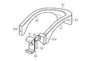
- the main body 20 is a U-shaped structure, and has a first end 20a and a second end 20b as two ends in the extending direction.
- the main body 20 has a structure in which a portion functioning as a housing for housing electronic components and the like extends in an arch shape from the first end 20a to the second end 20b.
- the support portion 30 is connected to the first end 20a of the main body portion 20. By supporting the photographing terminal on the supporting portion 30, the photographing terminal is attached to the first end 20 a via the supporting portion 30.
- the photographing terminal is a terminal having a photographing function and a communication function, and is, for example, a smartphone.
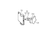
- the support unit 30 has a holding unit 31 for holding the imaging terminal, a support unit 30 extending from the holding unit 31 and connected to the main body unit 20, and having a function of adjusting the position and orientation of the holding unit 31. And a connecting portion 32 having the same.
- the holding unit 31 is configured to hold the photographing terminal by sandwiching the photographing terminal, for example.
- the connecting portion 32 is configured so that the position and the orientation of the holding portion 31 with respect to the first end 20a can be adjusted.
- the connecting portion 32 includes a slide mechanism, for example, and is configured to be able to change the length of the connecting portion 32 itself in the extending direction of the connecting portion 32, that is, in the direction from the first end 20a toward the holding portion 31. ing.
- the structure for changing the length of the connection part 32 is not limited to the slide mechanism, and for example, the connection part 32 has a structure in which a plurality of bends are made, and by extending the bend, the connection part 32 is extended from the first end 20a.
- the length of the connecting portion 32 in the direction toward the holding portion 31 may be increased. By changing the length of the connecting portion 32, the distance from the first end 20a to the holding portion 31 is changed, and thus the position of the holding portion 31 with respect to the first end 20a is changed.
- the connecting portion 32 includes a rotating mechanism, and the holding portion 31 is configured to be rotatable with respect to the first end 20a with the extending direction of the connecting portion 32 as the axial direction. Further, the angle of the holding portion 31 with respect to the plane orthogonal to the axial direction may be changeable. With these configurations, the orientation of the holding portion 31 with respect to the first end 20a can be adjusted.
- FIG. 3 shows a state in which the photographing terminal 50 is assembled to the support section 30.
- the photographing terminal 50 is assembled such that the camera forming the photographing unit is directed to the side opposite to the main body 20 with respect to the support 30.
- the position and orientation of the photographing terminal 50 with respect to the first end 20a are changed.
- the main body portion 20 includes a first side portion 21 including the first end 20a and extending from the first end 20a, and a second side portion 22 including the second end 20b and extending from the second end 20b. It has a curved portion 23 that extends in an arc shape and connects the first side portion 21 and the second side portion 22. That is, the curved portion 23 is a curved portion of the U-shaped main body portion 20, and the first side portion 21 extends substantially linearly from one of both ends of the curved portion 23, and the other of the both ends.
- the 2nd side part 22 is extended from it to substantially linear form.
- the first side portion 21 to which the photographing terminal 50 is attached may extend from the right end portion of the bending portion 23, or from the left end portion. It may extend.
- the material of the main body 20 is not particularly limited, and a part or all of the main body 20 is made of, for example, resin, metal, leather, wood, glass, paper such as corrugated board, or the like.
- the surface of the main body 20 may be covered with cloth, rubber or the like in order to improve decoration and touch.
- the central region of the bending portion 23 in the extending direction be configured so that the shape of the bending portion 23 can be widened so that the curvature radius of the bending becomes large.
- the central region may be made of an elastic member, or may have a bellows-like structure capable of expansion and contraction.
- the wearable device 10 has a housing portion 24 inside the second side portion 22 for housing a battery that supplies power to the photographing terminal 50.
- the accommodating portion 24 defines a space for accommodating the battery and has a terminal connecting portion to which a terminal such as USB of the battery is connected.
- the wiring extending from the terminal connecting portion passes through the inside of the curved portion 23, exits from the vicinity of the first end 20a to the outside of the main body portion 20, and is connected to the photographing terminal 50.
- a terminal connecting portion to which the above wiring is connected is provided near the first end 20a, and the terminal connecting portion and the photographing terminal 50 are connected to each other by wiring such as an arbitrary cable, so that the housing portion 24 is provided.
- the housed battery and the photographing terminal 50 are electrically connected.
- the accommodating portion 24 may be configured so that an accessory member for adjusting the size of the space for accommodating the batteries can be attached so that the accommodating portions 24 can accommodate batteries of a plurality of sizes.
- the housing portion 24 may be configured to be able to house the battery on the surface of the second side portion 22.
- the accommodating portion 24 may have a recess provided on the surface of the second side portion 22, and the battery may be accommodated in the accommodating portion 24 by fitting the battery in the recess.
- the wearable device 10 includes a voice output unit 25 and a voice input unit 26.
- the audio output unit 25 includes a speaker unit and outputs audio based on a signal from the photographing terminal 50.
- the voice input unit 26 includes a microphone unit, converts a voice input from the outside into a signal, and outputs the signal to the photographing terminal 50.
- the voice output unit 25 is preferably arranged in a portion of the main body 20 located near the user's ear when the wearable device 10 is worn.
- the audio output unit 25 is located near at least one of the boundary between the first side portion 21 and the bending portion 23 and near the boundary between the second side portion 22 and the bending portion 23, and is accommodated in the main body portion 20. Has been done.
- the voice input unit 26 may be disposed in a portion of the main body unit 20 that is located near the mouth of the user when the wearable device 10 is worn, or may be pulled out to the vicinity of the mouth of the user during use. It may be housed inside the main body 20.
- the voice input unit 26 is arranged near the second end 20b of the second side portion 22.
- the wiring for exchanging signals between the voice output unit 25 and the voice input unit 26 and the photographing terminal 50 passes through the inside of the main body unit 20 and goes out of the main body unit 20 from the vicinity of the first end 20a, and the photographing terminal. 50 is connected to an earphone jack or the like.
- a terminal connecting portion to which the above wiring is connected is provided in the vicinity of the first end 20a, and the terminal connecting portion and the photographing terminal 50 are connected by wiring such as an arbitrary cable, so that the audio output portion 25 The voice input unit 26 and the photographing terminal 50 are electrically connected.
- the wiring and terminal connecting unit for connecting the audio output unit 25 and the photographing terminal 50, and the wiring and terminal connecting unit for connecting the voice input unit 26 and the photographing terminal 50 may be common. , May be separate.
- each of the voice output unit 25 and the voice input unit 26 may exchange signals with the photographing terminal 50 by short-range wireless communication such as Bluetooth (registered trademark).
- the wearable device 10 is connected to a wireless communication unit (wireless communication circuit) that connects the audio output unit 25 and the audio input unit 26 to the photographing terminal 50 by the wireless communication to perform communication and control, and the wireless communication unit.
- a power supply unit that supplies power.
- the wireless communication unit and the power supply unit are housed in the main body unit 20.
- the power supply unit may be a primary battery, a secondary battery, a capacitor, or the like.
- the wearable device 10 includes, in addition to the above-described units, a vibration generation unit that generates vibration in the main body unit 20, a wind generation unit that generates wind from the main body unit 20 toward the user, and a scent generation unit that generates scent. May be provided.
- the vibration generator includes a vibrating body that vibrates in response to a signal from the photographing terminal 50.
- the wind generation unit includes a fan that rotates in response to a signal from the photographing terminal 50, and the scent generation unit holds a fragrance. For example, by placing the scent generating unit on the path of the wind from the wind generating unit, it is possible to generate a scented wind according to a signal from the photographing terminal 50.
- the wearable device 10 generates vibration, wind, and scent, so that when the user exchanges information through the photographing terminal 50, the sense of presence and interest are enhanced.
- the wearable device 10 may include a power generation unit including a solar cell.
- the solar cell is arranged on the upper surface of the main body 20, for example.
- the power generated by the power generation unit is supplied to the photographing terminal 50 and the power supply unit described above through the wiring.
- a portion other than the space for accommodating each of the above-mentioned portions may be a cavity or may be filled with an arbitrary material.
- the main body portion 20 is configured such that the weight per unit volume of only the main body portion 20 that does not include various electronic components to be housed, that is, the density is the largest in the central portion in the extending direction of the main body portion 20. Is preferably provided. Furthermore, it is preferable that the main body portion 20 be configured such that the density decreases from the central portion toward each of the first end 20a and the second end 20b.
- the main body portion 20 has a heavy region R1, a medium region R2, a low region R3, and a light region R4, which are four types of regions having different densities.
- the heavy region R1 has the highest density, and the heavy region R1, the middle region R2, the low region R3, and the light region R4 have smaller densities in this order.
- the overlapping region R1 is located in a region including the center of the curved portion 23 in the direction in which the main body 20 extends.
- a middle region R2, a low region R3, and a light region R4 are located in this order from the heavy region R1 toward the first end 20a, and even from the heavy region R1 toward the second end 20b, the middle region R2, the low region R3, The light region R4 is located in this order.
- the difference in density between the regions R1 to R4 is that, for example, the inside of the main body portion 20 is formed of a honeycomb structure, and the cross-sectional area of the cells of the honeycomb structure, that is, the unit regions forming the honeycomb structure is the most in the heavy region R1.
- This can be realized by configuring the area such that the area is small and the area is large in the order of the heavy area R1, the middle area R2, and the low area R3.
- the light region R4 is hollow and the housing portion 24 is arranged in the light region R4.
- the center of gravity of the wearable device 10 has the first end 20a and the second end in a state where the imaging terminal 50 is attached to the first end 20a and the battery is accommodated in the accommodating portion 24. It is easy to locate near the end of the main body 20 where 20b is located. As a result, when the wearable device 10 is worn, the wearable device 10 is likely to be lowered forward, and the load applied to the back neck of the user is increased, and the burden on the user is likely to be increased.
- the ratio of the areas R1 to R4 and the difference in density may be set according to the weight of the attached photographing terminal 50 and the battery. Further, since the battery is housed near the second end 20b, which is the end opposite to the first end 20a, which is the end to which the photographing terminal 50 is attached, the center of gravity of the wearable device 10 is either left or right. It is also possible to suppress bias. This also makes it easier to stabilize the position of the wearable device 10 when worn.
- the first side A weight may be added to the inside of one of the portion 21 and the second side portion 22 to form a weight difference from the other.
- the weight balance between the front and the rear instead of changing the density of the main body portion 20 as described above, or in addition to changing the density, the thicknesses of the bending portion 23 and the side portions 21 and 22 are changed. By changing the weight or adding a weight to the bending portion 23, the weight of the main body portion 20 may be adjusted so that the central region of the bending portion 23 becomes heavy.
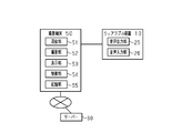
- the photographing terminal 50 is connected to a network and transmits and receives data to and from an external device such as a server 60 through the network.
- the network may be a general-purpose communication line such as the Internet or a dedicated communication line for communication of the photographing terminal 50.
- the photographing terminal 50 includes a communication unit 51, a photographing unit 52, a display unit 53, a control unit 54, and a storage unit 55.
- the communication unit 51 executes a connection process between the photographing terminal 50 and the server 60 via the network, and transmits and receives data between the photographing terminal 50 and the server 60.
- the photographing unit 52 includes a camera, photographs the surroundings of the photographing terminal 50, and generates photographing data that is still image or moving image data.
- the shooting data is transmitted to the server 60 via the communication unit 51.
- the display unit 53 includes a display panel such as a liquid crystal panel and displays an image.
- the display unit 53 displays at least one of the image captured by the capturing unit 52 and the image received by the communication unit 51 from the server 60.
- the control unit 54 has a configuration including a CPU and a volatile memory such as a RAM, and controls the processes of the communication unit 51, the photographing unit 52, and the display unit 53 based on the programs and data stored in the storage unit 55. , And controlling the output of signals to the wearable device 10.
- the storage unit 55 has a configuration including a non-volatile memory and stores programs and data necessary for the processing executed by the control unit 54.
- the photographing terminal 50 and the voice output unit 25 and the voice input unit 26 included in the wearable device 10 are connected by wire or wirelessly as described above. When signals are exchanged between the photographing terminal 50, the voice output unit 25, and the voice input unit 26 by wireless communication, the photographing terminal 50 connects the photographing terminal 50 and the wearable device 10 by wireless communication and transmits signals.
- a wireless communication unit for transmitting and receiving is provided.
- the voice output unit 25 of the wearable device 10 outputs voice based on the signal from the control unit 54 of the photographing terminal 50, and the voice input unit 26 converts the voice input from the outside into a signal and outputs the voice to the control unit 54. Output.
- the server 60 performs a predetermined process on the shooting data received from the shooting terminal 50. For example, the server 60 transmits the shooting data to a display device such as a large display, and causes the display device to display an image based on the shooting data. Further, for example, the server 60 may transmit data such as an image around the display device to the photographing terminal 50, and the image based on the data may be displayed on the display unit 53 of the photographing terminal 50.
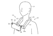
- FIG. 7 shows a user Ur in a state where the wearable device 10 to which the photographing terminal 50 is attached is worn when a smartphone is used as the photographing terminal 50.
- the main body 20 rides on the shoulder of the user Ur and surrounds the neck.
- the curved portion 23 is hung on the back neck portion, and the first side portion 21 and the second side portion 22 are lowered from the shoulder portion to the front of the chest.
- the lower surface of the main body portion 20 preferably has a curved surface shape that follows the shape of the shoulder portion. According to such a configuration, the body portion 20 easily follows the shoulder portion, so that the position of the wearable device 10 is easily stabilized during wearing.
- the photographing terminal 50 is attached to the support portion 30 connected to the first end 20a.
- the camera forming the image capturing unit 52 of the image capturing terminal 50 is directed toward the front of the user Ur, and the display unit 53 is directed toward the user Ur. That is, the display unit 53 is arranged at a position visible by the user Ur.
- a lens for adjusting the angle of view of the photographing unit 52 may be further attached to the photographing terminal 50.
- the wearable device 10 of the present embodiment is configured such that a photographing terminal 50 having a photographing function and a communication function can be attached, and photographing and transmission of photographing data are performed using the function of the photographing terminal 50. That is, the wearable device 10 itself does not have a shooting function and a shooting data transmission function. With such a configuration, it is possible to improve the photographing function and the communication function by attaching the photographing terminal 50 compatible with the new technology, for example. Therefore, it is possible to flexibly respond to a change in technology. As the photographing terminal 50, a terminal such as a smartphone that is highly popular and is easy to obtain in response to technological changes is used, so that the burden on the user is small compared to replacing the wearable device 10 itself. ..
- the wearable device 10 is used, for example, for remote communication. Specific examples include working such as meetings, medical treatment, and sightseeing.
- the photographing data generated based on the photographing terminal 50 photographing the surroundings is located in the second space S2 apart from the first space S1 in which the user Ur is located via the server 60. Is transmitted to the display device 70. Then, an image based on the received shooting data is displayed on the display device 70. The viewer Pr of the display device 70 can know the situation of the first space S1 by looking at the display device 70.
- the imaging area of the imaging terminal 50 is an area centered around the front of the chest of the user Ur and moves with the movement of the user Ur. Therefore, the viewer Pr can grasp the situation of the first space S1 from the position close to the viewpoint of the user Ur by looking at the display device 70, and whether the viewer Pr is in the first space S1. You can have an experience like.
- the voice uttered by the user Ur is input to the voice input unit 26 of the wearable device 10 and transmitted to the viewer Pr via the server 60 and the speaker located in the second space S2.
- the voice uttered by the viewer Pr is input to the microphone located in the second space S2, is output from the voice output unit 25 of the wearable device 10 via the server 60, and is transmitted to the user Ur.
- the user Ur and the viewer Pr located in the distant space can communicate with each other by voice.
- the viewer Pr can instruct the user Ur of the shooting area by the shooting terminal 50.
- the instruction to the user Ur may be performed using the vibration of the vibrating body.
- the vibrating body is arranged inside each of the first side portion 21 and the inside of the second side portion 22.
- a signal is sent to the shooting terminal 50 based on the viewer Pr operating the operating device located in the second space S2.
- a signal is sent from the photographing terminal 50 to the wearable device 10 so as to vibrate the vibrating body on the right side of the first side 21 and the second side 22.
- Signal transmission/reception between the photographing terminal 50 and the wearable device 10 may be performed by wire or wirelessly.
- the right part of the main body 20 vibrates, and this vibration is transmitted to the user Ur.
- the shooting area of the shooting terminal 50 moves according to the intention of the viewer Pr.
- the instruction to the user Ur can be intuitively transmitted to the user Ur.
- the user Ur can know the situation of the second space S2, and thus can communicate more smoothly with the viewer Pr. Further, if the image taken by the photographing terminal 50 is displayed on the display unit 53, the user Ur can confirm the photographing situation by the photographing terminal 50. Therefore, it is highly convenient for adjusting the shooting area by the shooting terminal 50.
- the wearable device 10 is configured such that the photographing terminal 50 can be attached to the end portion. Therefore, since the photographing function and the communication function can be changed by exchanging the photographing terminal 50, it is possible to flexibly cope with a change in technology.
- the support unit 30 supports the photographing terminal 50 so that the position and the direction of the photographing terminal 50 with respect to the main body unit 20 can be changed. According to such a configuration, by adjusting the position and orientation of the photographing terminal 50 using the support portion 30, the photographing area of the photographing terminal 50 can be adjusted, and thus the convenience of the user is enhanced.
- the main body portion 20 is provided with the accommodating portion 24 for accommodating the battery on the second side portion 22 extending from the end portion opposite to the end portion to which the photographing terminal 50 is attached.
- the wearable device 10 includes the voice output unit 25 and the voice input unit 26, voice communication is possible through the exchange of voice information using the photographing terminal 50.
- the density of the main body 20 is the largest in the central portion in the extending direction of the main body 20, when the photographing terminal 50 and the battery are assembled to the wearable device 10, that is, when the wearable device 10 is used. , It is possible to prevent the center of gravity from being biased toward the front of the user. Therefore, the position of the wearable device 10 when worn is easily stabilized, and the burden on the back neck of the user can be reduced. Further, if the density of the main body portion 20 decreases from the central portion toward each of the first end 20a and the second end 20b, the center of gravity can be more appropriately suppressed from being biased toward the front of the user, so that the above-described effect can be obtained. Is further enhanced.
- the support portion 30 may include a handle portion 33.
- the handle portion 33 is gripped by the user when using the wearable device.
- the positions of the support portion 30 and the photographing terminal 50 are stabilized, and photographing by the photographing terminal 50 proceeds smoothly. Further, even when the direction or length of the support portion 30 is changed, the change can be facilitated by performing the operation for the change while supporting the handle portion 33.
- the handle portion 33 may be provided at a position where the user can grab it. For example, the handle portion 33 extends downward from the connection portion 32.
- the main body 20 may have a structure in which an exterior is attached to the frame.
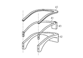
- the main body portion 20 includes an upper exterior portion 40, a frame portion 41, and a lower exterior portion 42.
- the body portion 20 is configured by assembling the frame portion 41 so that the frame portion 41 is housed in the space surrounded by the upper exterior portion 40 and the lower exterior portion 42.
- the upper exterior portion 40 and the lower exterior portion 42 are made of resin, for example, and the frame portion 41 is made of metal, for example.
- the lower exterior part 42 has a recess for accommodating the frame part 41, and the upper exterior part 40 closes the recess to define a space surrounding the frame part 41.
- the frame portion 41 has a U shape corresponding to the shape of the main body portion 20.
- the frame portion 41 has a weight portion 43 arranged at the center of the curved portion 23 of the main body portion 20.
- the weight per unit volume of the main body portion 20 is higher than that of other portions at the central portion. Also grows. Note that, for example, by changing the thickness of the frame portion 41 in the extending direction of the frame portion 41, the main body portion 20 is changed so that the weight per unit volume of the main body portion 20 changes in the extending direction of the main body portion 20. It may be configured.
- the main body 20 has a structure in which the exterior is assembled to the frame whose weight is adjusted in the extending direction of the main body 20, the main body 20 has a plurality of structures along the extending direction. It is easier to form the main body portion 20 as compared with the case where the main body portion 20 is formed by connecting the parts. Further, since the main body 20 can be formed by separately manufacturing the frame and the exterior and assembling them, mass production of the wearable device is easy.
- the weight of the main body portion 20 is such that the central portion and the end portion in the extending direction of the main body portion 20, that is, the central portion of the curved portion 23, the vicinity of the first end 20a of the first side portion 21, and the second side portion. It may be heavier than the other portions at the three points of 22 and the vicinity of the second end 20b.
- weights are added to the central portion of the curved portion 23, the first side portion 21 near the first end 20a, and the second side portion 22 near the second end 20b. Good.
- the part of the wearer's back that contacts the lower part of the back of the neck and the end of the part of the wearer's front that contacts the user's chest are separated from the user's body. Difficult to lift up. That is, since the main body portion 20 easily adheres to the user at three points, that is, the central portion and both end portions in the extending direction of the main body portion 20, in other words, both ends in the front-rear direction, the position of the wearable device with respect to the user is stable. Cheap. Further, since the heavy parts of the main body 20 are arranged in front of and behind the user, the center of gravity of the wearable device can be prevented from being biased to one of the front and the rear of the user.
- the position of the wearable device is stable, and the load of the wearable device is prevented from being concentrated on one point in front of or behind the user, so that the burden on the user when wearing the wearable device can be reduced.
- Such a configuration is particularly useful when the weight of the photographing terminal 50 and the battery is smaller than the weight of the wearable device and the influence of the weight of the photographing terminal 50 and the battery is small.
- the center of gravity of the main body 20 is near the center of the main body 20 in the front-rear direction, that is, the boundary between the curved portion 23 and the first side portion 21, and the curved portion 23 and the second side portion. It is arranged near the boundary with 22.
- the center of gravity of the main body 20 is arranged at a portion of the main body 20 that is in contact with the vicinity of the shoulder of the user.
- the heavy part in the main body 20 is located at the end of the main body 20 in the front-rear direction.
- the center of gravity of the wearable device is preferably located in the following range.
- the center of gravity is the center of gravity of the structure including the main body section 20 and the support section 30, and is the center of gravity in a state where the photographing terminal 50 and the battery are not attached.
- the extending direction of the first side portion 21 and the second side portion 22 is set as a reference direction, and the main body portion in the reference direction.
- the end where the first end 20a and the second end 20b are located is the front end
- the end where the bending portion 23 is located is the rear end.
- the position of the center of gravity of the wearable device in the plan view is the center of gravity position
- the distance from the front end to the center of gravity position in the reference direction is larger than 0.5 times the distance from the front end to the rear end in the reference direction and is 0.8. It is preferably less than twice, and more preferably 0.6 times or more and 0.7 times or less. If the center of gravity is located in the range, the position of the wearable device when worn is likely to be stable.
- the part of the main body 20 that contacts the user when the wearable device is worn by the user may be made of a flexible material.
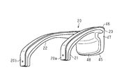
- the main body section 20 may include a cushion section 48.
- the cushion portion 48 is located on the lower surfaces of the first side portion 21 and the second side portion 22 and the front surface of the curved portion 23.
- the cushion portion 48 is made of urethane or a mesh material and has elasticity.
- the main body portion 20 includes an upper surface portion 46 that constitutes an upper surface of the main body portion 20, a core material portion 47 connected to the upper surface portion 46, and a cushion portion 48.
- the core material portion 47 has a shape corresponding to the outer shapes of the first side portion 21, the second side portion 22, and the curved portion 23, and the cushion portion 48 is attached to the surface of the core material portion 47.
- the upper surface portion 46 and the core material portion 47 are made of resin or metal, for example.
- the cushion portion 48 may cover the entire surface of the core material portion 47, not limited to the portion in contact with the user.
- the portion of the main body portion 20 that comes into contact with the user has flexibility, it is likely to be deformed along the body of the user. Therefore, when the wearable device is worn, the position of the wearable device with respect to the user is improved. Easy to stabilize. In addition, the user is less likely to feel a sense of discomfort due to the wearable device hitting the body, as compared to the case where the portion of the main body 20 that contacts the user is hard.
- the portion including the central portion of the curved portion 23 projects downward from the periphery thereof. That is, it is preferable that the bending portion 23 has a protruding portion 45 that is a portion that protrudes downward relative to other portions, and that the protruding portion 45 includes a central portion in the extending direction of the bending portion 23.
- the length of the protruding portion 45 in the vertical direction is preferably twice or more the average value of the thickness of the first side portion 21 and the second side portion 22 from the upper surface to the lower surface.
- the protrusion 45 has a step 49 on its front surface. That is, the step 49 is formed on the surface in contact with the user.
- the thickness of the protrusion 45 in the front-rear direction is thinner below the step 49 than above the step 49. Therefore, a gap is likely to be formed between the lower portion of the protrusion 45 and the user.
- the shape of the lower part of the back of the neck of the user in other words, the shape of the back near the neck of the user varies depending on the user, and the front surface of the protrusion 45, which is the surface in contact with the user, has a simple curved surface or a flat surface. In such a case, it is difficult to form the front surface into a shape that easily fits many users. As a result, the position where the gap between the protrusion 45 and the user is formed is different for each user, and the portion of the protrusion 45 that contacts the user is different for each user. There is a limit in stabilizing the position of the main body 20 with respect to the user.
- a specific position of the protruding portion 45 such as a corner portion of the stepped portion 49, can be easily brought into contact with the user, regardless of the difference in body shape between the users.
- a gap is easily formed between the user and a specific position of the protrusion 45, such as the lower portion of the protrusion 45. That is, it is possible to prevent the portion of the protruding portion 45 in contact with the user from varying for each user and to easily predefine the portion in contact with the user. Easy to stabilize.
- the image capturing terminal 50 may be attached to both the first end 20a and the second end 20b, and the user may be able to select which end the image capturing terminal 50 should be attached to.
- the support part 30 may be configured to be attachable to and detachable from both the first end 20a and the second end 20b.
- the support portion 30 may be connected to both the first end 20a and the second end 20b.
- the wearable device can accommodate the battery in both the first side portion 21 and the second side portion 22.
- the wearable device includes the housing portions 24 on both the first side portion 21 and the second side portion 22.
- the battery may be accommodated in the accommodating portion 24 that is located at a portion of the first side portion 21 and the second side portion 22 that extends from the end portion on the opposite side of the end portion to which the imaging terminal 50 is attached. ..
- the photographing terminal 50 and the battery can be arranged in the vicinity of different end portions, so that the deviation of the center of gravity between the left and right is suppressed.
- the photographing terminal 50 may be simultaneously attached to both the first end 20a and the second end 20b, and the batteries may be accommodated in both the first side portion 21 and the second side portion 22 at the same time.
- the support portion 30 may be attachable to and detachable from the main body portion 20, regardless of which end portion the photographing terminal 50 can be attached to.
- the support unit 30 may be replaceable with the support unit 30 having the holding unit 31 having a structure according to the model of the photographing terminal 50.
- the support portion 30 includes a detachable attachment member for adjusting the length of the connection portion 32, and the attachment member may be attached or detached according to the application and use environment of the wearable device.
- the wearable device is configured such that the photographing terminal 50 can be attached to at least one of the first end 20a and the second end 20b via the support portion 30 that is fixed to or removable from the main body portion 20. Good.
- connection part 32 may be configured so that only one of the position and the direction of the holding part 31 can be adjusted. Furthermore, in the support part 30, the position and orientation of the holding part 31 may be fixed. That is, the supporting unit 30 may have at least the function of supporting the photographing terminal 50 and relaying the connection between the photographing terminal 50 and the main body unit 20.
- At least one of the length of the first side portion 21, the length of the second side portion 22, and the length of the bending portion 23 may be adjustable according to the body type of the user. Further, the angle of the lower surfaces of the first side portion 21 and the second side portion 22 with respect to the user and the angle of the front surface of the bending portion 23 with respect to the user may be adjustable.
- the weight added to the curved portion 23 and the like in the body portion 20 may be removable. -The position of the accommodating portion 24 may be different from that in the above embodiment.
- the wearable device may include a plurality of accommodating portions 24 and be capable of accommodating a plurality of batteries with respect to one photographing terminal 50. In such a case, at least one accommodation part 24 may be located in the bending part 23.
- the wearable device includes the accommodation section 24. You don't have to.
- the wearable device may include a control unit that controls the electronic configuration of the wearable device.
- the control unit may include, for example, hardware elements used in a computer such as a CPU, a RAM, and a ROM, and software.
- the control unit is not limited to processing all the various processes by software.
- the control unit may include an application-specific integrated circuit (ASIC) that is dedicated hardware that executes at least a part of various processes.
- the control unit may include a circuit including one or more dedicated hardware circuits such as an ASIC, a microcomputer that is one or more processors that operate according to software that is a computer program, or a combination thereof.
- the wearable device 10 When the wearable device 10 does not need to transmit information by voice depending on the use and usage environment of the wearable device, or when the user can use the voice input/output of the photographing terminal 50 itself, the wearable device 10 At least one of the voice output unit 25 and the voice input unit 26 may not be provided.
- the photographing terminal 50 is sufficient for the photographing terminal 50 to have at least a photographing function and a communication function, and other functions are not particularly limited.
- the photographing terminal 50 does not have to include the display unit 53, and the image may not be displayed on the display unit 53 while the photographing terminal 50 is attached to the wearable device and used. ..
- the wearable device is not limited to the human body, and may be used by being attached to a humanoid robot.
- SYMBOLS 10 Wearable apparatus, 20... Main body part, 20a... 1st end, 20b... 2nd end, 21... 1st side part, 22... 2nd side part, 23... Bending part, 24... Accommodating part, 25... Audio output Section, 26... voice input section, 30... support section, 31... holding section, 32... connection section, 33... handle section, 40... upper exterior section, 41... frame section, 42... lower exterior section, 43... weight section, 45... Projection part, 46... Top surface part, 47... Heart material part, 48... Cushion part, 49... Step, 50... Photography terminal.
Landscapes
- Engineering & Computer Science (AREA)
- General Engineering & Computer Science (AREA)
- Mechanical Engineering (AREA)
- Signal Processing (AREA)
- Physics & Mathematics (AREA)
- Acoustics & Sound (AREA)
- Multimedia (AREA)
- General Physics & Mathematics (AREA)
- Studio Devices (AREA)
- Details Of Audible-Bandwidth Transducers (AREA)
- Telephone Set Structure (AREA)
- Accessories Of Cameras (AREA)
Abstract
ウェアラブル装置は、U字状を有する本体部を備える。本体部は、湾曲部と、湾曲部の2つの端部の一方から延びる第1側部と、上記2つの端部の他方から延びる第2側部とを備え、湾曲部が利用者の後頸部に掛けられて第1側部および第2側部が利用者の肩部から下げられる態様での装着が可能に構成されている。本体部は、第1側部の端部である第1端と、第2側部の端部である第2端とを有し、第1端と第2端との少なくとも一方に、撮影機能と通信機能とを有する端末を取付可能に構成されている。
Description
本開示は、人体等に装着されるウェアラブル装置に関する。
近年、人体の頭部や首部等に装着されるウェアラブル装置が多く開発されている。こうしたウェアラブル装置の一例は、撮影機能を有し、ウェアラブル装置の装着者の周囲を撮影可能に構成されている。さらに、上記ウェアラブル装置は、通信機能を有し、外部の装置との間で撮影データ等のデータを送受信することが可能に構成されている(例えば、特許文献1参照)。
一方、通信基盤が整備された環境下では通信技術の進歩が速まる一途であり、撮影技術もまた、その多様性が拡大する一途であるため、通信機能や撮影機能が付加されたウェアラブル装置においては、通信技術や撮影技術の変動に追従可能な柔軟性が新たに求められている。
本開示は、技術の変動に対し柔軟に対応可能なウェアラブル装置を提供することを目的とする。
上記課題を解決するウェアラブル装置は、U字状を有する本体部であって、湾曲部と、前記湾曲部の2つの端部の一方から延びる第1側部と、前記2つの端部の他方から延びる第2側部とを備え、前記湾曲部が利用者の後頸部に掛けられて前記第1側部および前記第2側部が前記利用者の肩部から下げられる態様での装着が可能に構成された前記本体部を備え、前記本体部は、前記第1側部の端部である第1端と、前記第2側部の端部である第2端とを有し、前記第1端と前記第2端との少なくとも一方に、撮影機能と通信機能とを有する端末を取付可能に構成されている。
上記構成によれば、ウェアラブル装置自身が撮影機能と送信機能とを有する場合と比較して、取り付ける端末の選択によって機能の向上等の技術の変更が可能であるため、技術の変動に対し柔軟に対応することができる。
上記構成において、前記第1端と前記第2端との少なくとも一方に接続される支持部であって、前記本体部に対する前記端末の位置および向きの少なくとも一方を変更可能に前記端末を支持する前記支持部を備えてもよい。
上記構成によれば、支持部を利用して端末の位置や向きを調整することで、端末の撮影領域を調整することができるため、利用者の利便性が高められる。
上記構成において、前記端末を支持する支持部であって、前記第1端と前記第2端との各々に対する着脱が可能に構成された前記支持部を備えてもよい。
上記構成において、前記端末を支持する支持部であって、前記第1端と前記第2端との各々に対する着脱が可能に構成された前記支持部を備えてもよい。
上記構成によれば、ウェアラブル装置の利用者は、正面に対して右側と左側とのいずれの端部に端末を取り付けるかを状況に応じて選択できるため、利便性が高められる。
上記構成において、前記第1側部および前記第2側部のうち、前記端末が取り付けられる端部を有する方に、前記端末に電力を供給するバッテリーを収容するための収容部を備えてもよい。
上記構成において、前記第1側部および前記第2側部のうち、前記端末が取り付けられる端部を有する方に、前記端末に電力を供給するバッテリーを収容するための収容部を備えてもよい。
上記構成によれば、端末とバッテリーとがウェアラブル装置に組み付けられた状態において、重心が左右のいずれかに偏ることが抑えられる。したがって、装着時におけるウェアラブル装置の位置が安定しやすくなる。
上記構成において、前記端末からの信号に基づいて音声を出力する音声出力部、および、入力された音声を信号に変換して前記端末に出力する音声入力部の少なくとも一方を備えてもよい。
上記構成によれば、端末を用いた音声情報の授受を通じて、ウェアラブル装置の利用者が外部と音声によるコミュニケーションを取ることができるようになる。
上記構成において、前記本体部における単位体積当たりの重さは、前記本体部の延びる方向における中央部にて最も大きくてもよい。
上記構成において、前記本体部における単位体積当たりの重さは、前記本体部の延びる方向における中央部にて最も大きくてもよい。
上記構成によれば、端末とバッテリーとがウェアラブル装置に組み付けられた状態において、重心が利用者の前方に偏ることが抑えられる。したがって、装着時におけるウェアラブル装置の位置が安定しやすくなるとともに、利用者の後頸部にかかる負担も軽減できる。
上記構成において、前記本体部における単位体積当たりの重さは、前記中央部から前記第1端と前記第2端との各々にむけて小さくなってもよい。
上記構成によれば、端末とバッテリーとがウェアラブル装置に組み付けられた状態において、重心が利用者の前方に偏ることがより的確に抑えられる。
上記構成によれば、端末とバッテリーとがウェアラブル装置に組み付けられた状態において、重心が利用者の前方に偏ることがより的確に抑えられる。
上記構成において、前記本体部の延びる方向における中央部および両端部の重さが、前記本体部の他の部分よりも重くてもよい。
上記構成によれば、本体部が、中央部と両端部との3点で利用者に密着しやすいため、利用者に対するウェアラブル装置の位置が安定しやすい。また、本体部のなかで重い部分が、利用者の前方と後方とに配置されるため、ウェアラブル装置の重心が利用者の前方と後方との一方に偏ることが抑えられる。したがって、ウェアラブル装置の位置が安定するとともに、ウェアラブル装置の荷重が利用者の前や後に集中してかかることが抑えられるため、ウェアラブル装置の装着時における利用者の負担も軽減できる。
上記構成によれば、本体部が、中央部と両端部との3点で利用者に密着しやすいため、利用者に対するウェアラブル装置の位置が安定しやすい。また、本体部のなかで重い部分が、利用者の前方と後方とに配置されるため、ウェアラブル装置の重心が利用者の前方と後方との一方に偏ることが抑えられる。したがって、ウェアラブル装置の位置が安定するとともに、ウェアラブル装置の荷重が利用者の前や後に集中してかかることが抑えられるため、ウェアラブル装置の装着時における利用者の負担も軽減できる。
上記構成において、前記湾曲部は、当該湾曲部の中央部を含む突出部を有し、前記突出部は、当該突出部の周囲よりも下方に突出していてもよい。
上記構成によれば、利用者の後頚部の下部付近で、湾曲部が利用者に接する領域を大きく確保しやすい。したがって、ウェアラブル装置の位置が安定しやすい。
上記構成によれば、利用者の後頚部の下部付近で、湾曲部が利用者に接する領域を大きく確保しやすい。したがって、ウェアラブル装置の位置が安定しやすい。
上記構成において、前記ウェアラブル装置を水平面に静置した状態で、前記ウェアラブル装置の真上から前記ウェアラブル装置を見た平面視において、前記第1側部および前記第2側部の延びる方向を基準方向とし、前記基準方向における前記本体部の両端のうち、前記第1端および前記第2端が位置する方の端部を前端とし、前記湾曲部が位置する方の端部を後端とするとともに、前記ウェアラブル装置の重心の位置を重心位置とするとき、前記基準方向における前記前端から前記重心位置までの距離は、前記基準方向における前記前端から前記後端までの距離の0.5倍より大きく0.8倍未満であってもよい。
上記構成によれば、ウェアラブル装置の重心が利用者の前と後との一方に偏ることが抑えられるため、ウェアラブル装置の位置が安定しやすい。
本開示によれば、ウェアラブル装置において、技術の変動に対し柔軟に対応することができる。
図1~図8を参照して、ウェアラブル装置の一実施形態を説明する。なお、以下の説明における上下左右前後の各方向は、ウェアラブル装置が利用者に装着された状態における方向である。
[全体構成]
図1が示すように、ウェアラブル装置10は、利用者の首部の周りに装着される本体部20と、撮影端末を支持可能に構成された支持部30とを備えている。
図1が示すように、ウェアラブル装置10は、利用者の首部の周りに装着される本体部20と、撮影端末を支持可能に構成された支持部30とを備えている。
本体部20は、U字状の構造体であり、その延びる方向における2つの端部として第1端20aと第2端20bとを有する。本体部20は、電子部品等を収容する筐体として機能する部分が、第1端20aから第2端20bへアーチ状に延びる構造を有する。
支持部30は、本体部20の第1端20aに接続されている。支持部30に撮影端末を支持させることで、第1端20aに撮影端末が支持部30を介して取り付けられる。撮影端末は、撮影機能および通信機能を有する端末であり、例えば、スマートフォンである。
[支持部]
支持部30の詳細な構成について説明する。図2が示すように、支持部30は、撮影端末を保持するための保持部31と、保持部31から延びて本体部20に接続されるとともに、保持部31の位置および向きの調整機能を有する接続部32とを備えている。
支持部30の詳細な構成について説明する。図2が示すように、支持部30は、撮影端末を保持するための保持部31と、保持部31から延びて本体部20に接続されるとともに、保持部31の位置および向きの調整機能を有する接続部32とを備えている。
保持部31は、例えば、撮影端末を挟むことにより、撮影端末を保持可能に構成されている。接続部32は、第1端20aに対する保持部31の位置および向きを調整可能に構成されている。具体的には、接続部32は、例えばスライド機構を含み、接続部32の延びる方向、すなわち、第1端20aから保持部31に向かう方向における接続部32自身の長さを変更可能に構成されている。なお、接続部32の長さの変更のための構造は、スライド機構に限らず、例えば、接続部32は、複数回折れ曲がった構造を有し、その屈曲を伸ばすことによって、第1端20aから保持部31に向かう方向における接続部32の長さを伸ばすことが可能に構成されていてもよい。接続部32の長さを変更することによって、第1端20aから保持部31までの距離が変更され、これにより、第1端20aに対する保持部31の位置が変更される。
また、接続部32は回転機構を含み、接続部32の延びる方向を軸方向として、第1端20aに対して保持部31が回転可能に構成されている。さらに、上記軸方向に直交する平面に対する保持部31の角度が変更可能とされていてもよい。これらの構成から、第1端20aに対する保持部31の向きが調整可能とされる。
図3は、撮影端末50が支持部30に組み付けられた状態を示す。撮影端末50は、撮影部を構成するカメラが、支持部30に対して本体部20とは反対側に向けられるように、組み付けられる。第1端20aに対する保持部31の位置および向きが変更されることによって、第1端20aに対する撮影端末50の位置および向きが変更される。
[本体部]
本体部20および本体部20が収容する各部の詳細について説明する。
図4が示すように、本体部20は、第1端20aを含み第1端20aから延びる第1側部21と、第2端20bを含み第2端20bから延びる第2側部22と、第1側部21と第2側部22とを繋ぐ弧状に延びる湾曲部23とを有している。すなわち、湾曲部23は、U字状の本体部20のなかの湾曲している部分であり、湾曲部23の両端の一方から、第1側部21が略直線状に延び、上記両端の他方から第2側部22が略直線状に延びている。本体部20を、その上面と対向する位置から見たとき、撮影端末50が取り付けられる第1側部21は、湾曲部23の右側の端部から延びていてもよいし、左側の端部から延びていてもよい。
本体部20および本体部20が収容する各部の詳細について説明する。
図4が示すように、本体部20は、第1端20aを含み第1端20aから延びる第1側部21と、第2端20bを含み第2端20bから延びる第2側部22と、第1側部21と第2側部22とを繋ぐ弧状に延びる湾曲部23とを有している。すなわち、湾曲部23は、U字状の本体部20のなかの湾曲している部分であり、湾曲部23の両端の一方から、第1側部21が略直線状に延び、上記両端の他方から第2側部22が略直線状に延びている。本体部20を、その上面と対向する位置から見たとき、撮影端末50が取り付けられる第1側部21は、湾曲部23の右側の端部から延びていてもよいし、左側の端部から延びていてもよい。
本体部20の材質は特に限定されず、本体部20の一部もしくは全部は、例えば、樹脂、金属、革、木、ガラス、段ボールなどの紙等から構成される。また、装飾や肌触りの向上のために、本体部20の表面が布やゴム等で覆われていてもよい。湾曲部23におけるその延びる方向の中央領域は、湾曲部23の形状を湾曲の曲率半径が大きくなるように広げることが可能に構成されていることが好ましい。例えば、上記中央領域は、弾性部材から構成されていてもよいし、伸縮が可能な蛇腹状の構造を有していてもよい。利用者がウェアラブル装置10を装着する際に、湾曲部23を広げてから本体部20を首部の周りに配置し、その後、湾曲部23を狭めて元の形状に戻すことで、装着が容易になる。
ウェアラブル装置10は、第2側部22の内部に、撮影端末50に電力を供給するバッテリーを収容するための収容部24を有している。収容部24は、バッテリーを収容する空間を区画するとともに、バッテリーにおけるUSB等の端子が接続される端子接続部を有している。端子接続部から延びる配線は、湾曲部23の内部を通り、第1端20aの付近から本体部20の外部に出て、撮影端末50に接続される。もしくは、第1端20aの付近に、上記配線が接続された端子接続部が設けられ、当該端子接続部と撮影端末50とが任意のケーブル等の配線で接続されることによって、収容部24に収容されたバッテリーと撮影端末50とが電気的に接続される。
収容部24は、複数の大きさのバッテリーを収容可能なように、バッテリーを収容する空間の大きさを調整するための付属部材を取り付け可能に構成されていてもよい。なお、収容部24は、第2側部22の内部にバッテリーを収容することに代えて、第2側部22の表面にバッテリーを収容可能に構成されていてもよい。例えば、収容部24は、第2側部22の表面に設けられた凹部を有し、当該凹部にバッテリーが嵌められることによって、バッテリーが収容部24に収容されてもよい。
ウェアラブル装置10は、音声出力部25および音声入力部26を備えている。音声出力部25は、スピーカーユニットを含み、撮影端末50からの信号に基づいて音声を出力する。音声入力部26は、マイクユニットを含み、外部から入力された音声を信号に変換して撮影端末50に出力する。
音声出力部25は、本体部20のなかで、ウェアラブル装置10の装着時に利用者の耳部の付近に位置する部分に配置されることが好ましい。例えば、音声出力部25は第1側部21と湾曲部23との境界の付近、および、第2側部22と湾曲部23との境界の付近の少なくとも一方に位置して本体部20に収容されている。
音声入力部26は、本体部20のなかで、ウェアラブル装置10の装着時に利用者の口部の付近に位置する部分に配置されてもよいし、使用時に利用者の口部近傍まで引き出されるように本体部20の内部に収容されていてもよい。例えば、音声入力部26は、第2側部22における第2端20bの付近に配置される。
音声出力部25および音声入力部26と撮影端末50との信号の授受のための配線は、本体部20の内部を通り、第1端20aの付近から本体部20の外部に出て、撮影端末50におけるイヤホンジャック等に接続される。もしくは、第1端20aの付近に、上記配線が接続された端子接続部が設けられ、当該端子接続部と撮影端末50とが任意のケーブル等の配線で接続されることによって、音声出力部25および音声入力部26と撮影端末50とが電気的に接続される。音声出力部25と撮影端末50とを接続するための配線および端子接続部と、音声入力部26と撮影端末50とを接続するための配線および端子接続部とは、共通であってもよいし、別々であってもよい。
なお、音声出力部25および音声入力部26の各々は、Bluetooth(登録商標)等の近距離での無線通信によって、撮影端末50と信号の授受を行ってもよい。この場合、ウェアラブル装置10は、上記無線通信によって音声出力部25および音声入力部26と撮影端末50とを接続して通信およびその制御を行う無線通信部(無線通信回路)と、無線通信部に電力を供給する電力供給部とを備える。無線通信部および電力供給部は、本体部20に収容される。電力供給部は、一次電池、二次電池、キャパシタ等であればよい。
ウェアラブル装置10は、上述の各部に加えて、本体部20に振動を発生させる振動発生部、本体部20から利用者に向けて風を発生させる風発生部、および、香りを発生させる香り発生部の少なくとも1つを備えていてもよい。振動発生部は、撮影端末50からの信号に応じて振動する振動体を含む。風発生部は、撮影端末50からの信号に応じて回転するファンを含み、香り発生部は、香料を保持する。例えば、風発生部からの風の通り道に香り発生部が位置することにより、撮影端末50からの信号に応じて香り付きの風を発生させることができる。このように、ウェアラブル装置10が振動や風や香りを発生させることにより、利用者が撮影端末50を通じて情報を授受する際に、臨場感や興趣が高められる。
また、ウェアラブル装置10は、太陽電池を含む電力生成部を備えていてもよい。太陽電池は、例えば、本体部20の上面に配置される。電力生成部が生成した電力は、配線を通じて撮影端末50や、上述の電力供給部に供給される。
本体部20の内部において、上述の各部の収容のための空間以外の部分は、空洞であってもよいし、任意の材料によって充填されていてもよい。ここで、本体部20は、収容する各種の電子部品を含まない本体部20のみの単位体積当たりの重さ、すなわち密度が、本体部20の延びる方向における中央部にて最も大きくなるように構成されていることが好ましい。さらに、本体部20は、上記密度が、上記中央部から第1端20aおよび第2端20bの各々に向けて小さくなるように構成されていることが好ましい。
例えば、図5が示すように、本体部20は、上記密度が異なる4種類の領域である重領域R1、中領域R2、低領域R3、軽領域R4を有する。重領域R1の密度が最も大きく、重領域R1、中領域R2、低領域R3、軽領域R4の順に、密度が小さくなる。
重領域R1は、本体部20が延びる方向における湾曲部23の中央を含む領域に位置する。重領域R1から第1端20aに向けて、中領域R2、低領域R3、軽領域R4がこの順に位置し、重領域R1から第2端20bに向けても、中領域R2、低領域R3、軽領域R4がこの順に位置する。
各領域R1~R4における密度の違いは、例えば、本体部20の内部をハニカム構造により構成し、ハニカム構造の目、すなわち、ハニカム構造を構成する単位領域の断面積を、重領域R1にて最も小さく、重領域R1、中領域R2、低領域R3の順に大きくなるように構成することで実現できる。また、軽領域R4は中空とされ、軽領域R4に収容部24が配置されることが好ましい。
本体部20の密度が均等であると、第1端20aに撮影端末50が取り付けられ、収容部24にバッテリーが収容された状態において、ウェアラブル装置10の重心が、第1端20aや第2端20bが位置する本体部20の端部付近に位置しやすい。その結果、ウェアラブル装置10の装着時に、ウェアラブル装置10が前方に下がりやすくなり、利用者の後頸部にかかる荷重が大きくなって利用者の負担が大きくなりやすい。これに対し、首部の後ろに配置される湾曲部23の中央領域から第1端20aおよび第2端20bの各々に向けて密度が小さくなれば、装着時におけるウェアラブル装置10の重心が端部寄りになることが抑えられる。したがって、ウェアラブル装置10の位置が安定しやすくなるとともに、利用者の後頸部にかかる負担も軽減される。
各領域R1~R4の割合や密度の差は、取り付けられる撮影端末50およびバッテリーの重さ等に応じて設定されればよい。
また、撮影端末50が取り付けられる端部である第1端20aとは反対側の端部である第2端20bの付近にバッテリーが収容されることで、ウェアラブル装置10の重心が、左右のいずれかに偏ることも抑えられる。これによっても、装着時におけるウェアラブル装置10の位置が安定しやすくなる。なお、撮影端末50とバッテリーとの重量の差が大きく、撮影端末50と反対側の端部にバッテリーを収容することのみによっては、左右の重さのバランスが取れない場合には、第1側部21および第2側部22の一方の内部に、他方との重量の差を形成するための重りが付加されてもよい。また、前後の重量のバランスについても、上述のように本体部20の密度を変えることに代えて、あるいは、密度を変えることに加えて、湾曲部23と側部21,22との太さを変えたり、湾曲部23に重りを付加したりすることによって、湾曲部23の中央領域が重くなるように本体部20の重さが調整されてもよい。
また、撮影端末50が取り付けられる端部である第1端20aとは反対側の端部である第2端20bの付近にバッテリーが収容されることで、ウェアラブル装置10の重心が、左右のいずれかに偏ることも抑えられる。これによっても、装着時におけるウェアラブル装置10の位置が安定しやすくなる。なお、撮影端末50とバッテリーとの重量の差が大きく、撮影端末50と反対側の端部にバッテリーを収容することのみによっては、左右の重さのバランスが取れない場合には、第1側部21および第2側部22の一方の内部に、他方との重量の差を形成するための重りが付加されてもよい。また、前後の重量のバランスについても、上述のように本体部20の密度を変えることに代えて、あるいは、密度を変えることに加えて、湾曲部23と側部21,22との太さを変えたり、湾曲部23に重りを付加したりすることによって、湾曲部23の中央領域が重くなるように本体部20の重さが調整されてもよい。
[電気的構成]
ウェアラブル装置10および撮影端末50の電気的な構成を説明する。
図6が示すように、撮影端末50は、ネットワークに接続され、例えばサーバ60である外部装置とネットワークを通じて相互にデータの送信および受信を行う。上記ネットワークは、インターネット等の汎用通信回線であってもよいし、撮影端末50の通信のための専用通信回線であってもよい。
ウェアラブル装置10および撮影端末50の電気的な構成を説明する。
図6が示すように、撮影端末50は、ネットワークに接続され、例えばサーバ60である外部装置とネットワークを通じて相互にデータの送信および受信を行う。上記ネットワークは、インターネット等の汎用通信回線であってもよいし、撮影端末50の通信のための専用通信回線であってもよい。
撮影端末50は、通信部51、撮影部52、表示部53、制御部54、および、記憶部55を備えている。
通信部51は、ネットワークを通じて、撮影端末50と、サーバ60との接続処理を実行し、撮影端末50とサーバ60との間でデータの送信および受信を行う。
通信部51は、ネットワークを通じて、撮影端末50と、サーバ60との接続処理を実行し、撮影端末50とサーバ60との間でデータの送信および受信を行う。
撮影部52は、カメラを含み、撮影端末50の周囲を撮影して、静止画または動画のデータである撮影データを生成する。撮影データは、通信部51を介して、サーバ60へ送信される。
表示部53は、液晶パネル等の表示パネルを含み、画像を表示する。例えば、表示部53は、撮影部52が撮影している画像、および、通信部51がサーバ60から受信した画像の少なくとも一方を表示する。
制御部54は、CPUや、RAM等の揮発性メモリを含む構成を有し、記憶部55に記憶されたプログラムやデータに基づいて、通信部51、撮影部52、表示部53の処理の制御、および、ウェアラブル装置10への信号の出力の制御を行う。
記憶部55は、不揮発性メモリを含む構成を有し、制御部54が実行する処理に必要なプログラムやデータを記憶している。
撮影端末50と、ウェアラブル装置10が備える音声出力部25および音声入力部26とは、上述のように、有線または無線で接続されている。撮影端末50と音声出力部25および音声入力部26との信号の授受が無線通信によって行われる場合には、撮影端末50は、無線通信によって撮影端末50とウェアラブル装置10とを接続して信号の送受信を行う無線通信部を備える。
撮影端末50と、ウェアラブル装置10が備える音声出力部25および音声入力部26とは、上述のように、有線または無線で接続されている。撮影端末50と音声出力部25および音声入力部26との信号の授受が無線通信によって行われる場合には、撮影端末50は、無線通信によって撮影端末50とウェアラブル装置10とを接続して信号の送受信を行う無線通信部を備える。
ウェアラブル装置10の音声出力部25は、撮影端末50の制御部54からの信号に基づいて音声を出力し、音声入力部26は、外部から入力された音声を信号に変換して制御部54に出力する。
サーバ60は、撮影端末50から受信した撮影データに対して、所定の処理を行う。例えば、サーバ60は、撮影データを、大型のディスプレイ等の表示装置に送信して、撮影データに基づく画像を表示装置に表示させる。また例えば、サーバ60は、上記表示装置の周辺の画像等のデータを撮影端末50に送信し、当該データに基づいた画像が撮影端末50の表示部53に表示されてもよい。
なお、撮影端末50が撮影データを送信する外部装置は、サーバ60に限らず、表示装置やパーソナルコンピュータ等であってもよい。
[利用態様]
ウェアラブル装置10の利用態様について説明する。図7は、撮影端末50としてスマートフォンを用いた場合について、撮影端末50が取り付けられたウェアラブル装置10を装着した状態の利用者Urを示す。本体部20は利用者Urの肩部に乗り、首部の周りを囲む。湾曲部23は後頸部に掛けられ、第1側部21と第2側部22とは、肩部から胸部の前方に下げられる。本体部20の下面は、肩部の形状に沿った曲面形状を有していることが好ましい。こうした構成によれば、本体部20が肩部に沿いやすいため、装着時にウェアラブル装置10の位置が安定しやすい。
[利用態様]
ウェアラブル装置10の利用態様について説明する。図7は、撮影端末50としてスマートフォンを用いた場合について、撮影端末50が取り付けられたウェアラブル装置10を装着した状態の利用者Urを示す。本体部20は利用者Urの肩部に乗り、首部の周りを囲む。湾曲部23は後頸部に掛けられ、第1側部21と第2側部22とは、肩部から胸部の前方に下げられる。本体部20の下面は、肩部の形状に沿った曲面形状を有していることが好ましい。こうした構成によれば、本体部20が肩部に沿いやすいため、装着時にウェアラブル装置10の位置が安定しやすい。
撮影端末50は、第1端20aに接続された支持部30に組み付けられる。撮影端末50の撮影部52を構成するカメラが、利用者Urの前方に向けられ、表示部53が、利用者Urに向けられる。すなわち、表示部53は、利用者Urによって視認可能な位置に配置される。撮影端末50にはさらに、撮影部52の画角を調整するためのレンズが取り付けられてもよい。
本実施形態のウェアラブル装置10は、撮影機能と通信機能とを有する撮影端末50を取付可能に構成されており、撮影端末50の機能を利用して、撮影および撮影データの送信が行われる。すなわち、ウェアラブル装置10そのものは、撮影機能と撮影データの送信機能とを有していない。こうした構成によれば、例えば新しい技術に対応した撮影端末50を取り付けることで、撮影機能と通信機能とを向上させることが可能である。そのため、技術の変動に対し柔軟に対応することができる。撮影端末50としては、スマートフォンのように、普及度が高く技術変動に対応した機種を手に入れやすい端末が用いられるため、ウェアラブル装置10そのものを買い替えることと比較して、利用者の負担は小さい。
図8を参照して、ウェアラブル装置10の利用環境の一例を説明する。ウェアラブル装置10は、例えば、遠隔でのコミュニケーションに用いられる。具体例としては、会議等の就労、診療、観光等が挙げられる。
図8が示すように、撮影端末50が周囲を撮影すること基づき生成された撮影データは、サーバ60を介して、利用者Urの位置する第1空間S1とは離れた第2空間S2に位置する表示装置70に送信される。そして、受信した撮影データに基づく画像が表示装置70に表示される。表示装置70の視聴者Prは、表示装置70を見ることで、第1空間S1の状況を知ることができる。
特に、撮影端末50による撮影領域は、利用者Urの胸部の前方付近を中心とする領域となり、利用者Urの移動に伴って移動する。したがって、視聴者Prは、表示装置70を見ることで、利用者Urの視点に近い位置から第1空間S1の状況を把握することが可能であり、視聴者Prが第1空間S1に居るかのような体験をすることができる。
また、利用者Urが発した音声が、ウェアラブル装置10の音声入力部26に入力され、サーバ60を介して、第2空間S2に位置するスピーカーを通じて視聴者Prに伝えられる。一方、視聴者Prの発した音声は、第2空間S2に位置するマイクに入力され、サーバ60を介して、ウェアラブル装置10の音声出力部25から出力されて利用者Urに伝えられる。これにより、離れた空間に位置する利用者Urと視聴者Prとが音声によってコミュニケーションを取ることが可能である。例えば、視聴者Prが、利用者Urに対して、撮影端末50による撮影領域の指示を行うこともできる。
また、ウェアラブル装置10が振動発生部を備える場合、利用者Urへの指示が、振動体の振動を利用して行われてもよい。例えば、第1側部21の内部と第2側部22の内部との各々に振動体が配置される。そして、視聴者Prが、撮影端末50による撮影領域を右に動かしたい場合は、視聴者Prが第2空間S2に位置する操作機を操作すること等に基づいて、撮影端末50に信号が送られ、第1側部21と第2側部22とのうち右に位置する側部の振動体を振動させるように、撮影端末50からウェアラブル装置10に信号が送られる。撮影端末50とウェアラブル装置10との信号の授受は有線または無線にて行われればよい。これにより、本体部20のなかの右部分が振動し、この振動が利用者Urに伝わる。利用者Urが、振動を感じた方向へ移動することで、撮影端末50による撮影領域が、視聴者Prの意図に沿って移動する。こうした構成によれば、利用者Urへの指示が、利用者Urに直感的に伝わりやすい。
また、第2空間S2に位置する撮影装置が第2空間S2を撮影したデータが、サーバ60を介して、撮影端末50に送信され、表示部53に表示される形態であれば、利用者Urは、第2空間S2の状況を知ることができるため、視聴者Prとより円滑なコミュニケーションが可能である。また、撮影端末50の撮影している画像が表示部53に表示される形態であれば、撮影端末50による撮影状況を利用者Urが確認できる。したがって、撮影端末50による撮影領域の調整に際して利便性が高い。
以上説明したように、本実施形態のウェアラブル装置10によれば、以下の効果が得られる。
(1)ウェアラブル装置10が、端部に撮影端末50を取付可能に構成されている。したがって、撮影端末50の交換によって撮影機能と通信機能とを変動させることができるため、技術の変動に対し柔軟に対応することができる。
(1)ウェアラブル装置10が、端部に撮影端末50を取付可能に構成されている。したがって、撮影端末50の交換によって撮影機能と通信機能とを変動させることができるため、技術の変動に対し柔軟に対応することができる。
(2)支持部30が、本体部20に対する撮影端末50の位置および向きを変更可能に撮影端末50を支持する。こうした構成によれば、支持部30を利用して撮影端末50の位置および向きを調整することで、撮影端末50の撮影領域を調整することができるため、利用者の利便性が高められる。
(3)本体部20が、撮影端末50が取り付けられる端部とは反対側の端部から延びる第2側部22に、バッテリーを収容するための収容部24を備えている。こうした構成によれば、撮影端末50とバッテリーとがウェアラブル装置10に組み付けられたとき、すなわち、ウェアラブル装置10の使用時において、重心が左右のいずれかに偏ることが抑えられる。したがって、装着時におけるウェアラブル装置10の位置が安定しやすくなる。
(4)ウェアラブル装置10が、音声出力部25および音声入力部26を備えているため、撮影端末50を用いた音声情報の授受を通じて、音声によるコミュニケーションが可能である。
(5)本体部20の密度が、本体部20の延びる方向における中央部にて最も大きければ、撮影端末50とバッテリーとがウェアラブル装置10に組み付けられたとき、すなわち、ウェアラブル装置10の使用時において、重心が利用者の前方に偏ることが抑えられる。したがって、装着時におけるウェアラブル装置10の位置が安定しやすくなるとともに、利用者の後頸部にかかる負担も軽減できる。さらに、本体部20の密度が、上記中央部から第1端20aおよび第2端20bの各々に向けて小さくなれば、重心が利用者の前方に偏ることがより的確に抑えられるため、上記効果がさらに高められる。
[変形例]
上記実施形態は、以下のように変更して実施することが可能である。
(変形例1)
図9が示すように、支持部30は、ハンドル部33を備えていてもよい。ハンドル部33は、ウェアラブル装置の使用時に、利用者によって掴まれる。利用者がハンドル部33を掴むことで、支持部30および撮影端末50の位置が安定し、撮影端末50による撮影が円滑に進む。また、支持部30の向きや長さを変更する場合にも、ハンドル部33を支持しながら当該変更のための操作を行うことで、当該変更が容易になる。ハンドル部33は、利用者が掴むことの可能な位置に設けられていればよい。例えば、ハンドル部33は、接続部32から下方に延びる。
上記実施形態は、以下のように変更して実施することが可能である。
(変形例1)
図9が示すように、支持部30は、ハンドル部33を備えていてもよい。ハンドル部33は、ウェアラブル装置の使用時に、利用者によって掴まれる。利用者がハンドル部33を掴むことで、支持部30および撮影端末50の位置が安定し、撮影端末50による撮影が円滑に進む。また、支持部30の向きや長さを変更する場合にも、ハンドル部33を支持しながら当該変更のための操作を行うことで、当該変更が容易になる。ハンドル部33は、利用者が掴むことの可能な位置に設けられていればよい。例えば、ハンドル部33は、接続部32から下方に延びる。
また、本体部20は、フレームに外装が組み付けられた構造を有していてもよい。例えば、図10が示すように、本体部20は、上部外装部40と、フレーム部41と、下部外装部42とを備える。そして、上部外装部40と下部外装部42とで囲まれる空間内にフレーム部41が収容されるように、これらが組み付けられることにより、本体部20が構成される。上部外装部40と下部外装部42とは、例えば樹脂製であり、フレーム部41は例えば金属製である。下部外装部42は、フレーム部41を収容する凹部を有し、当該凹部を上部外装部40が塞ぐことで、フレーム部41を囲む空間が区画される。
フレーム部41は、本体部20の形状に対応するU字状を有する。フレーム部41は、本体部20のうちの湾曲部23の中央部に配置される錘部43を有している。錘部43が湾曲部23の中央部、すなわち、本体部20の延びる方向における中央部に配置されることにより、当該中央部にて、本体部20における単位体積当たりの重さが他の部分よりも大きくなる。なお、例えば、フレーム部41の延びる方向においてフレーム部41の太さが変化することにより、本体部20における単位体積当たりの重さが本体部20の延びる方向において変化するように、本体部20が構成されていてもよい。
以上のように、本体部20が、本体部20の延びる方向における重量が調整されたフレームに、外装が組み付けられた構造を有しているため、本体部20がその延びる方向に沿って複数のパーツが接続されることにより形成される場合と比較して、本体部20の形成が容易である。また、フレームと外装とを別々に製造してこれらを組み付けることで本体部20を形成することができるため、ウェアラブル装置の量産も容易である。
また、本体部20の重さは、本体部20の延びる方向における中央部と端部、すなわち、湾曲部23の中央部と、第1側部21における第1端20a付近と、第2側部22における第2端20b付近と、の3点において、他の部分よりも重くなっていてもよい。例えば、本体部20のなかで、湾曲部23の中央部と、第1側部21における第1端20a付近と、第2側部22における第2端20b付近とに、重りが付加されていてもよい。
こうした構成によれば、ウェアラブル装置のなかで、利用者の後側で後頚部の下部付近に接する部分と、利用者の前側で利用者の胸に接する部分の端部とが利用者の身体から浮き上がりにくい。すなわち、本体部20が、本体部20の延びる方向における中央部と両端部との3点、言い換えれば、前後方向の両端で利用者に密着しやすいため、利用者に対するウェアラブル装置の位置が安定しやすい。また、本体部20のなかで重い部分が、利用者の前方と後方とに配置されるため、ウェアラブル装置の重心が利用者の前と後との一方に偏ることが抑えられる。したがって、ウェアラブル装置の位置が安定するとともに、ウェアラブル装置の荷重が利用者の前や後の一点に集中してかかることが抑えられるため、ウェアラブル装置の装着時における利用者の負担も軽減できる。こうした構成は、ウェアラブル装置の重量に対して撮影端末50およびバッテリーの重量が小さく、撮影端末50およびバッテリーの重量の影響が小さいときに特に有益である。
上記構成においては、本体部20の重心は、前後方向における本体部20の中央部の付近、すなわち、湾曲部23と第1側部21との境界部分、および、湾曲部23と第2側部22との境界部分の付近に配置される。言い換えれば、本体部20の重心は、本体部20のなかで、利用者の肩部付近に接する部分に配置される。一方で、本体部20なかの重い部分は、上記重心の位置とは異なり、前後方向における本体部20の端に位置する。このように、重心を、前後方向における本体部20の中央部に配置しつつ、本体部20のなかの重い部分は、前後方向における本体部20の端に配置することで、上述のように、ウェアラブル装置の位置が安定するとともに、ウェアラブル装置の装着時における利用者の負担が軽減できる。
なお、ウェアラブル装置の重心は、以下の範囲に位置することが好ましい。当該重心は、本体部20と支持部30とからなる構造体の重心であって、撮影端末50やバッテリーを取り付けない状態での重心である。
ウェアラブル装置を水平面に静置した状態で、ウェアラブル装置の真上からウェアラブル装置を見た平面視において、第1側部21および第2側部22の延びる方向を基準方向とし、基準方向における本体部20の両端のうち、第1端20aおよび第2端20bが位置する方の端部を前端とし、湾曲部23が位置する方の端部を後端とする。上記平面視でのウェアラブル装置の重心の位置を重心位置とするとき、基準方向における前端から重心位置までの距離は、基準方向における前端から後端までの距離の0.5倍より大きく0.8倍未満であることが好ましく、0.6倍以上0.7倍以下であることがより好ましい。重心が当該範囲に位置すれば、装着時におけるウェアラブル装置の位置が安定しやすい。
(変形例2)
本体部20のうち、ウェアラブル装置が利用者に装着された場合に利用者に接触する部分は、柔軟性を有する素材から構成されていてもよい。例えば、図11が示すように、本体部20は、クッション部48を備えていてもよい。クッション部48は、第1側部21および第2側部22の下面と湾曲部23の前面とに位置する。クッション部48は、ウレタンやメッシュ素材から形成されており、弾性を有する。
本体部20のうち、ウェアラブル装置が利用者に装着された場合に利用者に接触する部分は、柔軟性を有する素材から構成されていてもよい。例えば、図11が示すように、本体部20は、クッション部48を備えていてもよい。クッション部48は、第1側部21および第2側部22の下面と湾曲部23の前面とに位置する。クッション部48は、ウレタンやメッシュ素材から形成されており、弾性を有する。
図11に示す例では、本体部20は、本体部20の上面を構成する上面部46と、上面部46に接続された心材部47と、クッション部48とを備えている。心材部47は、第1側部21、第2側部22、および、湾曲部23の外形に対応する形状を有し、心材部47の表面にクッション部48が取り付けられている。上面部46および心材部47は、例えば樹脂製あるいは金属製である。なお、クッション部48は、利用者に接触する部分に限らず、心材部47の表面の全体を覆っていてもよい。
上記構成によれば、本体部20のなかで利用者に接触する部分が柔軟性を有することにより利用者の身体に沿って変形しやすいため、ウェアラブル装置の装着時に利用者に対するウェアラブル装置の位置が安定しやすい。また、本体部20のなかで利用者に接触する部分が硬い場合と比較して、ウェアラブル装置が身体に当たることに起因した違和感を利用者が覚えることが抑えられる。
また、湾曲部23の中央部を含む部分は、その周囲よりも下方に突出していることが好ましい。すなわち、湾曲部23は、他の部分よりも下方に突出した部分である突出部45を有し、突出部45には、湾曲部23の延びる方向における中央部が含まれていることが好ましい。例えば、上下方向における突出部45の長さは、第1側部21および第2側部22における上面から下面までの厚さの平均値の2倍以上であることが好ましい。こうした構成によれば、利用者の後頚部の下部付近で、湾曲部23が利用者に接する領域を大きく確保しやすい。したがって、ウェアラブル装置の位置が安定しやすい。また、湾曲部23の中央部の体積が大きくなるため、湾曲部23の中央部を重くするように本体部20に重りを付加することも容易である。
さらに、図12が示すように、突出部45は、その前面に段差49を有していることが好ましい。すなわち、段差49は、利用者に接する面に形成されている。突出部45の前後方向における厚みは、段差49よりも下方において、段差49の上方よりも薄くなっている。したがって、突出部45の下部と利用者との間には、隙間が形成されやすくなる。
利用者の後頚部の下部付近の形状、言い換えれば、利用者の首付近の背中の形状は、利用者によって様々であり、突出部45における利用者に接する面である前面を単純な曲面や平面とする場合、当該前面を多くの利用者に密着しやすい形状に形成することは困難である。結果として、突出部45と利用者との間の隙間の形成位置が利用者ごとに異なり、また、突出部45のなかで利用者に接する部分が利用者ごとに異なるようになるため、多くの利用者に対して本体部20の位置を安定させるには限界がある。
これに対し、突出部45に段差49を設けることにより、利用者ごとの体型の差異に関わらず、段差49の角部等、突出部45の特定の位置が利用者に接しやすくなり、また、突出部45の下部等、突出部45の特定の位置と利用者との間に隙間が形成されやすくなる。すなわち、突出部45のなかで利用者に接する部分が利用者ごとにばらつくことが抑えられ、当該利用者に接する部分を予め規定しやすいため、多くの利用者に対して本体部20の位置を安定させやすい。
また、利用者の後頚部および背中には背骨が通っているため、突出部45が段差49を有することにより、段差49が背骨に支持されて本体部20の位置が安定しやすい。
なお、こうした突出部45の構成は、本体部20の材料や組み立ての方式に関わらず適用可能であり、上記実施形態や変形例1にも適用できる。
なお、こうした突出部45の構成は、本体部20の材料や組み立ての方式に関わらず適用可能であり、上記実施形態や変形例1にも適用できる。
(他の変形例)
・第1端20aと第2端20bとの双方に撮影端末50を取り付けることが可能であって、いずれの端部に撮影端末50を取り付けるかを利用者が選択可能であってもよい。例えば、支持部30が第1端20aと第2端20bとのいずれにも着脱可能に構成されていてもよい。もしくは、第1端20aと第2端20bとの双方に支持部30が接続されていてもよい。こうした構成によれば、利用者は、ウェアラブル装置における右側と左側とのいずれの端部に撮影端末50を取り付けるかを状況に応じて選択できるため、利便性が高められる。
・第1端20aと第2端20bとの双方に撮影端末50を取り付けることが可能であって、いずれの端部に撮影端末50を取り付けるかを利用者が選択可能であってもよい。例えば、支持部30が第1端20aと第2端20bとのいずれにも着脱可能に構成されていてもよい。もしくは、第1端20aと第2端20bとの双方に支持部30が接続されていてもよい。こうした構成によれば、利用者は、ウェアラブル装置における右側と左側とのいずれの端部に撮影端末50を取り付けるかを状況に応じて選択できるため、利便性が高められる。
第1端20aと第2端20bとの双方に撮影端末50を取付可能である場合、ウェアラブル装置は、第1側部21と第2側部22とのいずれにもバッテリーを収容可能であることが好ましい。すなわち、ウェアラブル装置は、第1側部21と第2側部22との双方に収容部24を備えていることが好ましい。そして、第1側部21と第2側部22とのうち、撮影端末50が取り付けられた端部とは反対側の端部から延びる部分に位置する収容部24にバッテリーが収容されればよい。これにより、撮影端末50が取り付けられる端部が任意に選択される場合であっても、撮影端末50とバッテリーとを互いに異なる端部付近に配置することができるため、左右における重心の偏りが抑えられる。
なお、第1端20aと第2端20bとの双方に撮影端末50が同時に取り付けられ、第1側部21と第2側部22との双方にバッテリーが同時に収容されてもよい。
・撮影端末50がいずれの端部に取付可能であるかに関わらず、支持部30は本体部20に対して着脱可能であってもよく、さらに、本体部20に接続される支持部30が、撮影端末50の機種等に応じた構造の保持部31を有する支持部30に交換可能であってもよい。また、支持部30は、接続部32の長さを調整するための着脱可能な付属部材を含み、ウェアラブル装置の用途や使用環境等に応じて、上記付属部材が着脱されてもよい。要は、ウェアラブル装置は、本体部20に固定もしくは着脱可能とされた支持部30を介して、第1端20aと第2端20bとの少なくとも一方に撮影端末50が取り付け可能に構成されていればよい。
・撮影端末50がいずれの端部に取付可能であるかに関わらず、支持部30は本体部20に対して着脱可能であってもよく、さらに、本体部20に接続される支持部30が、撮影端末50の機種等に応じた構造の保持部31を有する支持部30に交換可能であってもよい。また、支持部30は、接続部32の長さを調整するための着脱可能な付属部材を含み、ウェアラブル装置の用途や使用環境等に応じて、上記付属部材が着脱されてもよい。要は、ウェアラブル装置は、本体部20に固定もしくは着脱可能とされた支持部30を介して、第1端20aと第2端20bとの少なくとも一方に撮影端末50が取り付け可能に構成されていればよい。
・支持部30において、接続部32は、保持部31の位置および向きの一方のみを調整可能に構成されていてもよい。さらに、支持部30において、保持部31の位置および向きは固定されていてもよい。すなわち、支持部30は、少なくとも撮影端末50を支持して撮影端末50と本体部20との接続を中継する機能を有していればよい。
・利用者の体型に応じて、第1側部21の長さ、第2側部22の長さ、および、湾曲部23の長さの少なくとも1つが調整可能であってもよい。また、利用者に対する第1側部21および第2側部22の下面の角度や、利用者に対する湾曲部23の前面の角度が調整可能であってもよい。
・本体部20のなかで湾曲部23等に付加される重りは、着脱可能であってもよい。
・収容部24の位置は、上記実施形態とは異なっていてもよい。また、ウェアラブル装置が複数の収容部24を備え、1つの撮影端末50に対して複数のバッテリーを収容可能であってもよい。こうした場合、少なくとも1つの収容部24は、湾曲部23に位置していてもよい。あるいは、ウェアラブル装置の用途等に応じて、例えばウェアラブル装置の連続使用時間が短い場合等、バッテリーによる撮影端末50への電力の供給が不要である場合には、ウェアラブル装置は収容部24を備えていなくてもよい。
・収容部24の位置は、上記実施形態とは異なっていてもよい。また、ウェアラブル装置が複数の収容部24を備え、1つの撮影端末50に対して複数のバッテリーを収容可能であってもよい。こうした場合、少なくとも1つの収容部24は、湾曲部23に位置していてもよい。あるいは、ウェアラブル装置の用途等に応じて、例えばウェアラブル装置の連続使用時間が短い場合等、バッテリーによる撮影端末50への電力の供給が不要である場合には、ウェアラブル装置は収容部24を備えていなくてもよい。
・ウェアラブル装置が振動発生部や無線通信部等を備える場合に、ウェアラブル装置は、ウェアラブル装置における電子的構成を制御する制御部を備えていてもよい。制御部は、例えば、CPU、RAM、ROMなどのコンピュータに用いられるハードウェア要素、および、ソフトウェアを備えてもよい。制御部は、各種の処理を全てソフトウェアで処理するものに限らない。例えば、制御部は、各種の処理のうちの少なくとも一部の処理を実行する専用のハードウェアである特定用途向け集積回路(ASIC)を備えてもよい。制御部は、ASICなどの1つ以上の専用のハードウェア回路、コンピュータプログラムであるソフトウェアに従って動作する1つ以上のプロセッサであるマイクロコンピュータ、あるいは、これらの組み合わせ、を含む回路を備えてもよい。
・ウェアラブル装置の用途や使用環境等に応じて、音声による情報の伝達が不要である場合や、撮影端末50自身での音声の入出力を利用者が利用できる場合には、ウェアラブル装置10は、音声出力部25および音声入力部26の少なくとも一方を備えていなくてもよい。
・撮影端末50は、少なくとも撮影機能と通信機能とを備えていればよく、その他の機能は特に限定されない。例えば、撮影端末50は表示部53を備えなくてもよいし、撮影端末50がウェアラブル装置に取り付けられて使用されている間には、表示部53への画像の表示が行われなくてもよい。
・ウェアラブル装置は、人体に限らず、人型のロボットに装着されて用いられてもよい。
10…ウェアラブル装置、20…本体部、20a…第1端、20b…第2端、21…第1側部、22…第2側部、23…湾曲部、24…収容部、25…音声出力部、26…音声入力部、30…支持部、31…保持部、32…接続部、33…ハンドル部、40…上部外装部、41…フレーム部、42…下部外装部、43…錘部、45…突出部、46…上面部、47…心材部、48…クッション部、49…段差、50…撮影端末。
Claims (10)
- U字状を有する本体部であって、湾曲部と、前記湾曲部の2つの端部の一方から延びる第1側部と、前記2つの端部の他方から延びる第2側部とを備え、前記湾曲部が利用者の後頸部に掛けられて前記第1側部および前記第2側部が前記利用者の肩部から下げられる態様での装着が可能に構成された前記本体部を備え、
前記本体部は、前記第1側部の端部である第1端と、前記第2側部の端部である第2端とを有し、前記第1端と前記第2端との少なくとも一方に、撮影機能と通信機能とを有する端末を取付可能に構成されている
ウェアラブル装置。 - 前記第1端と前記第2端との少なくとも一方に接続される支持部であって、前記本体部に対する前記端末の位置および向きの少なくとも一方を変更可能に前記端末を支持するように構成された前記支持部を備える
請求項1に記載のウェアラブル装置。 - 前記端末を支持するように構成された支持部であって、前記第1端と前記第2端との各々に対する着脱が可能に構成された前記支持部を備える
請求項1または2に記載のウェアラブル装置。 - 前記第1側部および前記第2側部のうち、前記端末が取り付けられる端部を有する方に、前記端末に電力を供給するバッテリーを収容するための収容部を備える
請求項1~3のいずれか一項に記載のウェアラブル装置。 - 前記端末からの信号に基づいて音声を出力する音声出力部、および、入力された音声を信号に変換して前記端末に出力する音声入力部の少なくとも一方を備える
請求項1~4のいずれか一項に記載のウェアラブル装置。 - 前記本体部における単位体積当たりの重さは、前記本体部の延びる方向における中央部にて最も大きい
請求項1~5のいずれか一項に記載のウェアラブル装置。 - 前記本体部における単位体積当たりの重さは、前記中央部から前記第1端と前記第2端との各々にむけて小さくなる
請求項6に記載のウェアラブル装置。 - 前記本体部の延びる方向における中央部および両端部の重さが、前記本体部の他の部分よりも重い
請求項1~5のいずれか一項に記載のウェアラブル装置。 - 前記湾曲部は、当該湾曲部の中央部を含む突出部を有し、前記突出部は、当該突出部の周囲よりも下方に突出している
請求項1~8のいずれか一項に記載のウェアラブル装置。 - 前記ウェアラブル装置を水平面に静置した状態で、前記ウェアラブル装置の真上から前記ウェアラブル装置を見た平面視において、
前記第1側部および前記第2側部の延びる方向を基準方向とし、前記基準方向における前記本体部の両端のうち、前記第1端および前記第2端が位置する方の端部を前端とし、前記湾曲部が位置する方の端部を後端とするとともに、前記ウェアラブル装置の重心の位置を重心位置とするとき、前記基準方向における前記前端から前記重心位置までの距離は、前記基準方向における前記前端から前記後端までの距離の0.5倍より大きく0.8倍未満である
請求項1~9のいずれか一項に記載のウェアラブル装置。
Priority Applications (3)
| Application Number | Priority Date | Filing Date | Title |
|---|---|---|---|
| JP2020567724A JP7452440B2 (ja) | 2019-01-24 | 2020-01-24 | ウェアラブル装置 |
| CN202080008847.8A CN113287294B (zh) | 2019-01-24 | 2020-01-24 | 可穿戴装置 |
| US17/443,394 US11991430B2 (en) | 2019-01-24 | 2021-07-26 | Wearable apparatus |
Applications Claiming Priority (2)
| Application Number | Priority Date | Filing Date | Title |
|---|---|---|---|
| JP2019-010546 | 2019-01-24 | ||
| JP2019010546 | 2019-01-24 |
Related Child Applications (1)
| Application Number | Title | Priority Date | Filing Date |
|---|---|---|---|
| US17/443,394 Continuation US11991430B2 (en) | 2019-01-24 | 2021-07-26 | Wearable apparatus |
Publications (1)
| Publication Number | Publication Date |
|---|---|
| WO2020153489A1 true WO2020153489A1 (ja) | 2020-07-30 |
Family
ID=71736976
Family Applications (1)
| Application Number | Title | Priority Date | Filing Date |
|---|---|---|---|
| PCT/JP2020/002576 Ceased WO2020153489A1 (ja) | 2019-01-24 | 2020-01-24 | ウェアラブル装置 |
Country Status (4)
| Country | Link |
|---|---|
| US (1) | US11991430B2 (ja) |
| JP (1) | JP7452440B2 (ja) |
| CN (1) | CN113287294B (ja) |
| WO (1) | WO2020153489A1 (ja) |
Cited By (1)
| Publication number | Priority date | Publication date | Assignee | Title |
|---|---|---|---|---|
| JP2022138245A (ja) * | 2021-03-10 | 2022-09-26 | シャープ株式会社 | 音声処理システム及び音声処理方法 |
Families Citing this family (2)
| Publication number | Priority date | Publication date | Assignee | Title |
|---|---|---|---|---|
| CN116389674B (zh) * | 2023-03-28 | 2024-04-26 | 射阳港海会议服务有限公司 | 一种远程会议视频装置 |
| CN223990001U (zh) * | 2025-04-02 | 2026-03-13 | 智涛 | 折叠支架 |
Citations (2)
| Publication number | Priority date | Publication date | Assignee | Title |
|---|---|---|---|---|
| JP2007013873A (ja) * | 2005-07-04 | 2007-01-18 | Sony Corp | ヘッドホン装置 |
| JP2016161934A (ja) * | 2015-02-27 | 2016-09-05 | マイポーブ インコーポレイテッド | カメラを具備した端末機用据置台 |
Family Cites Families (16)
| Publication number | Priority date | Publication date | Assignee | Title |
|---|---|---|---|---|
| JP2001282391A (ja) * | 2000-03-31 | 2001-10-12 | Sharp Corp | 小型携帯端末 |
| JP4335609B2 (ja) * | 2003-08-18 | 2009-09-30 | アルプス電気株式会社 | 入出力装置 |
| JP4278625B2 (ja) * | 2005-03-09 | 2009-06-17 | 康利 松田 | 携帯電話用品 |
| TW200911005A (en) * | 2007-08-24 | 2009-03-01 | Merry Electronics Co Ltd | Neck-wear wireless earphone |
| US8382692B1 (en) * | 2010-06-10 | 2013-02-26 | John Chao | Neck and spine support device for a neck in flexion |
| KR101250951B1 (ko) * | 2012-07-23 | 2013-04-09 | 정윤석 | 위험요소 감지 기능을 가지는 양귀 삽입형 보청기 및 이를 이용한 위험요소 감지 시스템 |
| CN104469121B (zh) * | 2013-09-16 | 2018-08-10 | 联想(北京)有限公司 | 信息处理方法及电子设备 |
| KR101587714B1 (ko) * | 2014-05-26 | 2016-01-21 | 이승호 | 스마트 기기 거치용 목걸이 |
| KR101561005B1 (ko) * | 2015-03-25 | 2015-10-15 | 양승철 | 물리치료 기능을 구비한 마사지장치 |
| CN204561641U (zh) * | 2015-04-09 | 2015-08-19 | 厦门麓山新材料科技有限公司 | 贴肩式u型头颈枕 |
| GB201603129D0 (en) * | 2016-02-23 | 2016-04-06 | Leatt Corp | Neck protection devices |
| US9833058B2 (en) * | 2016-03-31 | 2017-12-05 | Chester Bryant | Electronic device harness assembly |
| KR200482913Y1 (ko) * | 2016-05-24 | 2017-03-15 | 강철민 | 휴대용 단말기 거치대가 구비된 넥 밴드형 블루투스 핸즈프리장치 |
| CN106231033A (zh) * | 2016-08-31 | 2016-12-14 | 海盐东方口琴厂 | 一种颈挂式手机支架 |
| JP3209658U (ja) | 2017-01-20 | 2017-03-30 | 台灣微米科技股▲ふん▼有限公司Digilife Technologies Co., Ltd. | 首掛け式撮像装置 |
| CN208365164U (zh) * | 2018-04-09 | 2019-01-11 | 王光英 | 一种使用移动电子设备时的穿戴式肩颈保护装置 |
-
2020
- 2020-01-24 WO PCT/JP2020/002576 patent/WO2020153489A1/ja not_active Ceased
- 2020-01-24 JP JP2020567724A patent/JP7452440B2/ja active Active
- 2020-01-24 CN CN202080008847.8A patent/CN113287294B/zh active Active
-
2021
- 2021-07-26 US US17/443,394 patent/US11991430B2/en active Active
Patent Citations (2)
| Publication number | Priority date | Publication date | Assignee | Title |
|---|---|---|---|---|
| JP2007013873A (ja) * | 2005-07-04 | 2007-01-18 | Sony Corp | ヘッドホン装置 |
| JP2016161934A (ja) * | 2015-02-27 | 2016-09-05 | マイポーブ インコーポレイテッド | カメラを具備した端末機用据置台 |
Cited By (2)
| Publication number | Priority date | Publication date | Assignee | Title |
|---|---|---|---|---|
| JP2022138245A (ja) * | 2021-03-10 | 2022-09-26 | シャープ株式会社 | 音声処理システム及び音声処理方法 |
| JP7752949B2 (ja) | 2021-03-10 | 2025-10-14 | シャープ株式会社 | 音声処理システム及び音声処理方法 |
Also Published As
| Publication number | Publication date |
|---|---|
| JP7452440B2 (ja) | 2024-03-19 |
| US11991430B2 (en) | 2024-05-21 |
| US20210352194A1 (en) | 2021-11-11 |
| CN113287294B (zh) | 2026-03-17 |
| JPWO2020153489A1 (ja) | 2021-11-25 |
| CN113287294A (zh) | 2021-08-20 |
Similar Documents
| Publication | Publication Date | Title |
|---|---|---|
| CN109407757B (zh) | 显示系统 | |
| CN107071605B (zh) | 智能3d耳机 | |
| CN113196147A (zh) | 模块化眼镜系统、设备和方法 | |
| KR101662617B1 (ko) | 블루투스헤드셋 및 이를 포함하는 손목시계 | |
| US11991430B2 (en) | Wearable apparatus | |
| US20190204617A1 (en) | Wearable device | |
| JP2018064264A (ja) | 情報処理装置、情報処理方法およびプログラム | |
| EP1175809B1 (en) | Headset | |
| KR20150111198A (ko) | 이동 단말기 | |
| CN104169781A (zh) | 具有输入和输出结构的可佩戴设备 | |
| JP2017221427A (ja) | ゲームシステム、方法、およびゲームプログラム | |
| US9807490B1 (en) | Vibration transducer connector providing indication of worn state of device | |
| JP2013115799A (ja) | 耳掛け型補聴器 | |
| EP3340645B1 (en) | Ear unit for a portable sound device | |
| WO2019126402A1 (en) | Ear-worn device | |
| KR101971425B1 (ko) | 다기능 웨어러블 스마트폰 거치대 | |
| KR100962720B1 (ko) | 근거리 무선통신용 헤드셋 | |
| US12593187B2 (en) | Measurement system and measurement method | |
| CN209419804U (zh) | 一种骨传导耳机 | |
| KR20160032563A (ko) | 와치 타입 단말기 및 이동 단말기 어셈블리 | |
| CN214151241U (zh) | 一种vr虚拟现实显示屏用调节设备 | |
| CN211860512U (zh) | 无线耳机,头戴式耳机支架及耳机组件 | |
| CN210298026U (zh) | 一种变换式无线耳机 | |
| KR102870785B1 (ko) | 무선으로 오디오 신호를 수신하는 음향 출력 장치 | |
| WO2021193713A1 (ja) | ウェアラブル情報機器 |
Legal Events
| Date | Code | Title | Description |
|---|---|---|---|
| 121 | Ep: the epo has been informed by wipo that ep was designated in this application |
Ref document number: 20744919 Country of ref document: EP Kind code of ref document: A1 |
|
| ENP | Entry into the national phase |
Ref document number: 2020567724 Country of ref document: JP Kind code of ref document: A |
|
| NENP | Non-entry into the national phase |
Ref country code: DE |
|
| 122 | Ep: pct application non-entry in european phase |
Ref document number: 20744919 Country of ref document: EP Kind code of ref document: A1 |