WO2020153192A1 - 電子機器 - Google Patents
電子機器 Download PDFInfo
- Publication number
- WO2020153192A1 WO2020153192A1 PCT/JP2020/001066 JP2020001066W WO2020153192A1 WO 2020153192 A1 WO2020153192 A1 WO 2020153192A1 JP 2020001066 W JP2020001066 W JP 2020001066W WO 2020153192 A1 WO2020153192 A1 WO 2020153192A1
- Authority
- WO
- WIPO (PCT)
- Prior art keywords
- pair
- power supply
- supply terminal
- covers
- power
- Prior art date
- Legal status (The legal status is an assumption and is not a legal conclusion. Google has not performed a legal analysis and makes no representation as to the accuracy of the status listed.)
- Ceased
Links
Images









Classifications
-
- A—HUMAN NECESSITIES
- A47—FURNITURE; DOMESTIC ARTICLES OR APPLIANCES; COFFEE MILLS; SPICE MILLS; SUCTION CLEANERS IN GENERAL
- A47L—DOMESTIC WASHING OR CLEANING; SUCTION CLEANERS IN GENERAL
- A47L9/00—Details or accessories of suction cleaners, e.g. mechanical means for controlling the suction or for effecting pulsating action; Storing devices specially adapted to suction cleaners or parts thereof; Carrying-vehicles specially adapted for suction cleaners
- A47L9/28—Installation of the electric equipment, e.g. adaptation or attachment to the suction cleaner; Controlling suction cleaners by electric means
-
- G—PHYSICS
- G05—CONTROLLING; REGULATING
- G05D—SYSTEMS FOR CONTROLLING OR REGULATING NON-ELECTRIC VARIABLES
- G05D1/00—Control of position, course, altitude or attitude of land, water, air or space vehicles, e.g. using automatic pilots
- G05D1/02—Control of position or course in two dimensions
-
- H—ELECTRICITY
- H01—ELECTRIC ELEMENTS
- H01R—ELECTRICALLY-CONDUCTIVE CONNECTIONS; STRUCTURAL ASSOCIATIONS OF A PLURALITY OF MUTUALLY-INSULATED ELECTRICAL CONNECTING ELEMENTS; COUPLING DEVICES; CURRENT COLLECTORS
- H01R13/00—Details of coupling devices of the kinds covered by groups H01R12/70 or H01R24/00 - H01R33/00
- H01R13/44—Means for preventing access to live contacts
-
- H—ELECTRICITY
- H02—GENERATION; CONVERSION OR DISTRIBUTION OF ELECTRIC POWER
- H02J—ELECTRIC POWER NETWORKS; CIRCUIT ARRANGEMENTS OR SYSTEMS FOR SUPPLYING OR DISTRIBUTING ELECTRIC POWER; SYSTEMS FOR STORING ELECTRIC ENERGY
- H02J7/00—Circuit arrangements for charging or discharging batteries or for supplying loads from batteries
Definitions
- the present invention relates to an electronic device, and more particularly, to an electronic device including a self-propelled device and a charging unit that charges the self-propelled device.
- Patent Document 1 discloses an electric cleaning device including a self-propelled electric vacuum cleaner having a built-in battery and a charging device for charging the self-propelled electric vacuum cleaner.
- a pair of left and right power receiving terminals are provided on the bottom plate facing the floor of the self-propelled vacuum cleaner, and the left and right sides of the self-propelled vacuum cleaner returned on the mounting table of the charging device.
- a pair of left and right power supply terminals that are mechanically and electrically connected to the pair of power reception terminals and supply power to the battery are provided.
- the self-propelled vacuum cleaner is separated from the charging device and the self-propelled vacuum cleaner returns to the charging device.
- the power supply terminal and the power receiving terminal may not be mechanically and electrically connected without stopping at a predetermined position for some reason.
- the present invention has been made in view of the above problems, and an object thereof is to provide an electronic device that can more reliably mechanically and electrically connect a power supply terminal and a power reception terminal.
- a travelable casing having a bottom plate facing the floor surface, a battery provided in the casing, and a forward portion in the forward direction side or a backward portion in the backward direction of the casing are provided.
- a pair of power supply terminal insertion openings having a front opening or a rear opening, a pair of power reception terminals respectively provided in the pair of power supply terminal insertion openings in the housing, and the housing receiving the output of the battery
- a self-propelled device having a power receiving side control unit for controlling the traveling of The mounting table, and the battery which is inserted into the pair of power supply terminal insertion ports of the self-propelled device provided on the mounting table and returned to the mounting table and mechanically and electrically connected to the pair of power receiving terminals
- an electronic device including a charging unit having
- an electronic device including a self-propelled device and a charging unit with improved reliability.
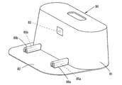
- FIG. 6 is a perspective view showing a state where a pair of left and right power supply terminal covers of the charging unit shown in FIG. 5 are opened.
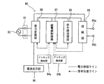
- FIG. 6 is a block diagram of an electric circuit of the charging unit shown in FIG. 5. It is a 1st explanatory view showing the state where the self-propelled device of a 1st embodiment returns to a charging unit. It is a 2nd explanatory view showing the state where the self-propelled device of a 1st embodiment returns to a charging unit. It is a 3rd explanatory view showing the state where the self-propelled device of a 1st embodiment returns to a charging unit. It is a bottom view of the self-propelled device in the electronic device of 2nd Embodiment. It is a bottom view of the self-propelled device in the electronic device of 3rd Embodiment. It is a perspective view of a state where a pair of right and left power supply terminal covers of a charging unit in an electronic equipment of a 3rd embodiment are opened.
- FIG. 1 is a perspective view of the self-propelled device in the electronic device according to the first embodiment of the present invention
- FIG. 2 is an internal configuration of the self-propelled device as viewed from the side of the first embodiment
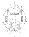
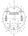
- FIG. 3 is a bottom view of the self-propelled device of the first embodiment
- FIG. 4 is a block diagram of a control circuit of the self-propelled device of the first embodiment.
- the self-propelled device is configured as a self-propelled electric vacuum cleaner, a self-propelled ion generator, a self-propelled indoor monitoring device, and the like.
- a cleaning robot cleans the floor surface by self-propelled on the floor surface, sucking dust on the floor surface together with air, and exhausting the air from which the dust is removed.
- the cleaning robot A has a forward direction Y1 side as a front part and a backward direction Y2 side as a rear part (see FIG. 3).
- the cleaning robot A includes a disc-shaped casing 1 having a bottom plate 1a facing the floor surface and capable of traveling, and an exhaust port 41 is provided on the upper surface of the casing 1.
- the housing 1 is made of an electrically insulating material (for example, ABS resin).
- the bottom plate 1a includes a rotating brush 3, a pair of left and right side brushes 4, a suction port 11, a pair of left and right driving wheels 5, a rear wheel 7, a floor detection sensor 13, a pair of left and right power receiving terminals 2a and 2b for charging, and a power source.
- a switch (toggle switch) 62 is provided.
- the suction passage 10 connected to the suction port 11, the dust collecting portion 20 provided on the downstream side of the flow of the air in the suction passage 10, and the dust collecting portion.
- An electric blower 30 provided on the downstream side of the wind flow of 20 and an exhaust path 50 connecting the electric blower 30 and the exhaust port 41 are provided.
- a control board 15 on which a control circuit of the cleaning robot A, which will be described later, is mounted, and a battery (storage battery) 14 are incorporated.
- the housing 1 includes a lid 1ba and a top plate 1b having a circular shape in plan view having an exhaust port 41 formed at a rear position of the lid 1ba, and outer peripheral portions of the bottom plate 1a and the top plate 1b. And a side plate 1c having a circular ring shape in a plan view.
- the side plate 1c is divided into a front part and a rear part, and the front part of the side plate 1c is a bumper.
- An input unit 63 (see FIG. 4) for inputting a stop command is provided.
- the bottom plate 1a (see FIG. 3) is formed with a plurality of holes that allow the lower portions of the pair of drive wheels 5 to project from the inside of the housing 1 to the outside. Further, in front of the side plate 1c, as shown in FIG. 1, a plurality of ultrasonic sensors 9 for detecting obstacles in the traveling direction of the cleaning robot A are provided.
- the pair of drive wheels 5 are rotatably provided around a shaft 5a on the same axis X in the left-right direction which is parallel to the bottom plate 1a of the housing 1.
- the housing 1 advances and retreats, and when the drive wheels 5 rotate in opposite directions, the housing 1 rotates.
- the rotating shafts 5a of the pair of drive wheels 5 are connected to each other so as to individually obtain rotational force from a pair of drive wheel motors, which will be described later, and each drive wheel motor is attached to the inner surface of the bottom plate 1a of the housing 1. It is fixed directly or through a suspension mechanism.
- the rear wheel 7 is a free wheel and is rotatably provided at the rear portion of the bottom plate 1a of the housing 1 so as to come into contact with the floor surface.
- the pair of drive wheels 5 are arranged in the middle in the front-rear direction with respect to the housing 1, the front part of the housing 1 is floated from the floor surface, and the total weight of the cleaning robot A is compared with the pair of drive wheels 5 and the rear.
- the weight is distributed in the front-rear direction with respect to the housing 1 so as to be supported by the wheel 7. As a result, the dust in front of the route can be guided to the suction port 11.
- the above-mentioned rotary brush 3 is provided at the inlet of the suction port 11 so as to be rotatable around a horizontal axis parallel to the bottom plate 1a of the housing 1. Further, the side brushes 4 on both the left and right sides of the suction port 11 in the bottom plate 1a are configured to rotate about a rotation axis in a direction perpendicular to the bottom plate 1a.
- the rotary brush 3 is formed by implanting a brush in a spiral shape on the outer peripheral surface of a roller that is a rotary shaft, and is driven by a rotary brush drive motor described later.
- the side brush 4 has a plurality of brush bundles radially provided at the lower end of the rotating shaft.
- the rotation shaft of the side brush 4 is supported on the inner surface of the bottom plate 1a of the housing 1 and driven by a side brush drive motor described later.
- the housing 1 has a notch at the rear of the bottom plate 1a for mounting the rear wheel 7 rotatably about a vertical axis. It has a recess 1aa. Further, flat vertical surfaces 1ab are provided between the left and right portions of the cutout recess 1aa and the bottom plate 1a. Further, the left and right vertical surfaces 1ab and the bottom plate 1a are provided with slit-shaped power supply terminal insertion openings 1ac extending forward from the respective vertical surfaces 1ab.
- each power supply terminal insertion opening 1ac has a rear opening 1ad having a shape that widens rearward (outward), and a cut 1ae provided in the front-back direction in the bottom plate 1a so as to communicate with the rear opening 1ad.
- Each of the power supply terminal insertion ports 1ac has a storage space for the power reception terminals 2a and 2b. The storage space has a width wider than each cut 1ae.
- the housing 1 is provided with a pair of left and right insertion port covers 8 provided on the bottom plate 1a so as to cover the cuts 1ae of the pair of left and right power supply terminal insertion ports 1ac so as to be exposed, and a pair of left and right insertion port covers 8.
- a pair of right and left power receiving side urging members 12 are provided.
- the insertion port cover 8 is made of an insulating resin material, like the bottom plate 1a.
- the bottom plate 1a of the housing 1 has a cover storage portion 16 that supports each insertion port cover 8 so as to be capable of reciprocating in the front-rear direction.
- Each cover accommodating portion 16 has a substantially U shape in a plan view that is open to the rear side, and the bent end portions on the rear end side thereof regulate the rearward movement of each insertion port cover 8.
- Each power-reception-side urging member 12 is provided inside the housing 1 so as to urge each insertion port cover 8 in a direction (in this case, rearward) of closing the notch 1ae of each power supply terminal insertion port 1ac.
- a compression coil spring is used as each power receiving side biasing member 12, and each insertion port cover 8 is biased rearward by the compression coil spring.
- Each power receiving side urging member 12 is not limited to the compression coil spring, and may be a tension coil spring, a leaf spring, or the like.
- the pair of power receiving terminals 2a and 2b have a U shape (clip shape) in a plan view that is opened rearward, and a pair of hemispherical surfaces facing each other at both end portions on the rear end side thereof. Have bulging portions respectively.
- the notch 1ae of each power supply terminal insertion opening 1ac is arranged between the pair of bulging portions of each power reception terminal 2a, 2b.
- the shape of each of the power receiving terminals 2a and 2b is not limited to the clip shape, but both sides of blade-shaped power feeding terminals 85a and 85b (see FIG. 7) described later can be reliably mechanically and electrically contacted. From the viewpoint, the clip shape is preferable.
- the control circuit mounted on the control board 15 (see FIG. 2) for controlling the cleaning robot A includes a microcomputer including a CPU 51, a ROM 52, and a RAM 53, as shown in FIG.
- a motor driver circuit 71 that controls two side brush drive motors 70 that drive the two side brushes 4, a motor driver circuit 68 that controls a DC motor 69 incorporated in the electric blower 30, a power switch 62, and various sensors 67.
- the various sensors 67 include the floor detection sensor 13, the ultrasonic sensor 9, and the infrared detection sensor 6 described above.
- As the DC motor 69 a permanent magnet excitation DC motor is used.
- a capacitance type switch is used as the input unit 63.
- the output power of the battery 14 is supplied to the motor driver circuits 57, 71, 59 and 68, respectively, and the power receiving side control unit 54 and the input side are supplied. It is also supplied to the unit 63, the sensor control unit 66, and the like.
- the power receiving side control unit 54 receives the output of the battery 14 and controls the traveling of the housing 1.
- the CPU 51 of the power receiving side control unit 54 is a central processing unit, performs arithmetic processing of signals received from the input unit 63 and various sensors 67 based on a program stored in advance in the ROM 52, and motor driver circuits 57, 71, 59. , 68 and so on.
- the RAM 53 stores various operating conditions of the cleaning robot A, outputs of various sensors 67, and the like. Further, the RAM 53 can store a travel map of the cleaning robot A. The travel map is information related to travel such as the travel route and travel speed of the cleaning robot A, and can be stored in the RAM 53 by the user in advance, or can be automatically recorded by the cleaning robot A itself during the cleaning operation. Further, the power receiving side control unit 54 has a function of detecting the terminal voltage of the battery 14 and the like to detect the remaining charge of the battery 14.
- the housing 1 is self-propelled in a predetermined range and the air containing dust on the floor surface is sucked from the suction port 11. Inhale.
- the dust on the floor is scraped up by the rotation of the rotary brush 3 and guided to the suction port 11. Further, the dust on the side of the suction port 11 is guided to the suction port 11 by the rotation of the side brush 4.
- the dust-containing air sucked into the housing 1 through the suction port 11 passes through the suction passage 10 of the housing 1 and flows into the dust collecting box 21 of the dust collecting unit 20, as shown in FIG.
- the airflow that has flowed into the dust collection box 21 passes through the filter 22 of the dust collection unit 20 and the electric blower 30, passes through the exhaust passage 50, and is discharged to the exhaust port 41.
- the dust contained in the air flow in the dust collection box 21 is captured by the filter 22, the dust is accumulated in the dust collection box 21. In this way, the floor surface is cleaned.
- the cleaning robot A can swivel by the left and right drive wheels 5 rotating forward in the same direction and moving forward, rotating backward in the same direction and moving backward, and rotating in opposite directions.
- the cleaning robot A when the cleaning robot A approaches a large step (cliff), reaches the periphery of the cleaning area, or collides with an obstacle on the path, the floor surface detection sensor 13 (see FIG. 3) and others. Various sensors notify the power receiving side control unit 54 (see FIG. 4), and the drive wheels 5 stop. Next, the left and right drive wheels 5 are rotated in opposite directions to change their directions. Accordingly, the cleaning robot A can perform self-propelled cleaning while avoiding large steps or obstacles over the entire installation place or the entire desired range. Then, when the predetermined cleaning work is completed, the cleaning robot A returns to the charging unit (charging stand) installed in the room as described later.
- the charging unit charging stand
- FIG. 5 is a perspective view of the charging unit in the electronic device according to the first embodiment of the present invention
- FIG. 6 is a front view of the charging unit shown in FIG.
- FIG. 7 is a perspective view of the charging unit shown in FIG. 5 with a pair of left and right power supply terminal covers open
- FIG. 8 is a block diagram of an electric circuit of the charging unit shown in FIG.
- the charging unit 80 has a plate-like shape to which a main body portion 81 and a power supply terminal, which will be described later, are connected so as to horizontally extend forward from the bottom surface of the main body portion 81.
- the terminal block 82 is provided, and the main body 81 and the terminal block 82 are formed of an insulating resin material.
- the front side of the charging unit 80 is a direction in which infrared rays are emitted from the infrared transmitting unit 83 described later (direction toward the terminal block 82 side).
- the main body 81 and the terminal block 82 may be integrally molded, or may be separately molded and assembled.
- the main body 81 detects the return of the cleaning robot A to the charging unit 80 by an infrared transmitter 83 that emits infrared rays to the cleaning robot A to indicate a return path, and a pair that detects the mechanical contact with the cleaning robot A.
- Docking detection units (power supply side detection units) 84a and 84b, a control circuit, and a power supply display unit 90 (see FIG. 8).
- a limit switch can be used as each of the docking detectors 84a and 84b.
- the terminal block 82 has, on its upper surface, a pair of left and right power supply terminals that mechanically and electrically connect to the pair of left and right power reception terminals 2a and 2b of the cleaning robot A (see FIG. 3) to supply charging power to the battery 14.
- the pair of power supply terminal covers 86a and 86b are made of an insulating resin material.
- the pair of power supply terminals 85a and 85b provided on the terminal block 82 of the charging unit 80 are blades that stand vertically and extend in the front-rear direction. Each is formed in a shape.
- the power supply terminals 85a and 85b are inserted into the power supply terminal insertion opening 1ac through the rear opening 1ad and the notch 1ae of the pair of power supply terminal insertion openings 1ac of the cleaning robot A that has returned to the terminal block 82, and then the pair of power supply terminals It is mechanically and electrically connected to the power receiving terminals 2a and 2b.
- the rear ends of the power supply terminals 85a and 85b are arranged in the main body 81 and fixed to a support member (not shown) in the main body 81.
- the pair of power supply terminal covers 86a and 86b provided on the terminal block 82 of the charging unit 80 has a tunnel shape (a substantially inverted U-shaped cross-sectional shape) that covers the pair of blade-shaped power supply terminals 85a and 85b exposed to the outside. Has been formed. Further, it is preferable that the lengths of the power supply terminal covers 86a and 86b be such that the power supply terminals 85a and 85b on the terminal block 82 can be completely covered when viewed from directly above (see FIG. 5).
- each of the power supply terminal covers 86a and 86b from the terminal block 82 is set to be higher than the height of the bottom plate 1a of the cleaning robot A mounted on the terminal block 82 and lower than the height of the cutout recess 1aa. (See FIG. 2).
- the front ends of the power supply terminal covers 86a and 86b exposed to the outside and the rear end of the main body 81 are open, and the rear end is supported by a support member (not shown) in the main body 81 so as to be slidable in the front-rear direction.
- the terminal block 82 has a shape in which the cleaning robot A can ride up during charging, but it may have a shape that does not climb up during charging.
- each guide groove 82a is wide so that both the power supply terminal covers 86a and 86b and the power supply terminals 85a and 85b fit within the guide grooves 82a.
- Fine guide grooves (four in total) may be formed on both the left and right sides of each of the 85b so that only the lower end portions of the power supply terminal covers 86a and 86b fit into the respective narrow guide grooves.
- the pair of power supply terminals 85a and 85b are arranged inside the pair of guide grooves 82a inside the center position of the pair of power supply terminal covers 86a and 86b in the left-right direction.
- the outer sides in the left-right direction of the pair of power supply terminal covers 86a and 86b are formed in a more gentle arc shape than the inner side.
- the outer side of each of the power supply terminal covers 86a and 86b which are likely to receive an impact from the outside, can be formed in a gentle arc shape to reduce the impact from the outside.
- the power supply terminal covers 86a and 86b are easily opened, and the power supply terminal insertion openings 1ac of the power supply terminals 85a and 85b (see FIG. 3). The insertability into is improved.
- FIG. 7 illustrates a state in which the power supply terminal covers 86a and 86b are moved rearward and opened against the biasing force of the power supply side biasing members 81a. Note that, in FIG. 7, a part of each of the power supply terminal covers 86 a and 86 b protrudes from the main body 81 at a position where the power supply terminal covers 86 a and 86 b are completely opened.
- each power feeding side biasing member 81a a tension coil spring is used as each power feeding side biasing member 81a, one end of each tension coil spring is fixed to the inner surface on the front side inside the main body 81, and each power feeding terminal cover 86a, 86b The other end of each tension coil spring is fixed to mounting pieces 86aa and 86ba provided at the ends.
- the power supply side urging members 81a are not limited to the tension coil springs, and may be compression coil springs, leaf springs, or the like.
- the control circuit includes a power feeding side control unit 87, a power conversion unit 88, the infrared transmission unit 83, a connection unit 89, the docking detection units 84a, 84b, The power source display unit 90 and the power source plug 91 are provided.
- the power conversion unit 88 converts the commercial power (AC100V, 50/60Hz) input from the commercial power supply 92 via the power plug 91 into charging power (DC24V) and control power (DC5V) for the battery 14 (see FIG. 4). It is designed to be converted.
- the converted control power is supplied to the power supply side control unit 87, the infrared transmission unit 83, and the connection unit 89.
- the power supply side control unit 87 causes the power conversion unit 88.
- the charging power is output to the power supply terminals 85a and 85b through the connecting portion 89.
- the charging unit 80 is connected to the commercial power source 92 via the power plug 91, and the power source display section 90 is displayed.
- the cleaning robot A needs to return the cleaning robot A to the charging unit 80 by the power receiving side control unit 54 (see FIG. 4) when the cleaning robot A finishes a predetermined cleaning operation or the remaining charge of the battery 14 decreases to an allowable value. If the cleaning robot A detects infrared rays from the infrared transmitter 83 of the charging unit 80 by the infrared detection sensor 6 (see FIG. 1), the cleaning robot A advances along the return path indicated by the infrared rays. To do.
- the cleaning robot A when the cleaning robot A approaches the charging unit 80 to some extent, the cleaning robot A reverses 180° and then retreats and returns to the charging unit 80.
- the cleaning robot A contacts (presses) the pair of docking detectors 84a and 84b via the pair of power supply terminal covers 86a and 86b, the pair of power supply terminals 85a and 85b (see FIG. 8) receives the pair of power receiving terminals, respectively.
- the terminals 2a and 2b (see FIG. 4) are in contact with each other and are mechanically and electrically connected. As a result, a DC voltage of 24 V is output from the connecting portion 89 between the power supply terminals 85a and 85b, and the battery 14 is charged via the power receiving terminals 2a and 2b.
- FIG. 9 is a first explanatory diagram showing a state in which the self-propelled device of the first embodiment returns to the charging unit
- FIG. 10 shows a second state of the self-propelled device of the first embodiment returning to the charging unit
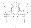
- FIG. 11 is a third explanatory diagram showing a state in which the self-propelled device according to the first embodiment returns to the charging unit.
- FIG. 9 shows a state in which the cleaning robot A has been approached to the charging unit 80 to some extent and then inverted by 180° before docking.
- the pair of power receiving terminals 2a and 2b of the cleaning robot A are arranged on the substantially extended lines of the pair of power feeding terminals 85a and 85b of the charging unit 80.
- the pair of insertion port covers 8 are urged to the rear side by the pair of power receiving side urging members 12, respectively, whereby the slits 1ae of the pair of power supply terminal insertion ports 1ac are inserted into the respective insertion ports. It is covered with a cover 8 so as not to be exposed to the outside.
- the cleaning robot A since the cleaning robot A is not in contact with the pair of power supply terminal covers 86a and 86b in the state before docking, the pair of power supply terminal covers 86a and 86b are separated by the pair of power supply side biasing members 81a (see FIG. 7). Each of them is biased forward, thereby covering the pair of power supply terminals 85a and 85b. Therefore, even when the floor surface is cleaned by the cleaning robot A, the power supply terminals 85a and 85b are covered with the power supply terminal covers 86a and 86b, so that dust is unlikely to adhere to the power supply terminals 85a and 85b.
- the cleaning robot A moves backward from the pre-docking state shown in FIG. 9 to the docking operation as shown in FIG.
- the rear wheel 7 rides on the terminal block 82 (see FIG. 5) of the charging unit 80 and the left and right vertical surfaces arranged at the rear of the cleaning robot A. 1ab hits and presses the left and right power supply terminal covers 86a and 86b.
- the left and right power supply terminal covers 86a and 86b move rearward against the urging force of the power supply side urging member 81a (see FIG. 7), and the rear opening of the left and right power supply terminal insertion openings 1ac of the cleaning robot A is performed.
- the front ends of the left and right power supply terminals 85a and 85b enter into the portion 1ad.
- the rear opening 1ad has a shape that widens toward the rear (outward), the front ends of the power supply terminals 85a and 85b are easily inserted into the rear opening 1ad.
- the front ends of the left and right power supply terminals 85a and 85b come into contact with the rear ends of the left and right insertion port covers 8 as shown in FIG. 10, and the cleaning robot A further retracts, as shown in FIG.
- the left and right power supply terminals 85a, 85b push the front side of the left and right insertion opening covers 8 against the biasing force of each power receiving side biasing member 12 to open them forward.
- the front ends of the power supply terminals 85a and 85b are inserted into the left and right power supply terminal insertion openings 1ac in a state of passing through the respective cuts 1ae and mechanically connected to the left and right power reception terminals 2a and 2b.
- the blade-shaped power supply terminals 85a and 85b are sandwiched between the power reception terminals 2a and 2b, and the docking is completed.
- the left and right vertical surfaces 1ab of the cleaning robot A push the left and right power supply terminal covers 86a and 86b of the charging unit 80 into the main body 81 by a predetermined amount, whereby the left and right docking detection portions 84a and 84b (FIG. 8). (See reference) is detected by being pressed by the rear ends of the left and right power supply terminal covers 86a and 86b. That is, when the power receiving terminals 2a and 2b and the power feeding terminals 85a and 85b are sufficiently connected, the detection signals from the docking detection units 84a and 84b are output to the power feeding side control unit 87.
- a DC voltage is output from the connecting portion 89 between the power supply terminals 85a and 85b, and the battery 14 is charged via the power receiving terminals 2a and 2b, and is also electrically connected.
- the power receiving side control unit 54 controls the drive wheel motors 55 and 56 via the motor driver circuit 57 so that the cleaning robot A stops the backward movement.
- the pair of power receiving terminals 2a and 2b of the cleaning robot A are mechanically and electrically connected to the pair of power feeding terminals 85a and 85b of the charging unit 80 in this manner, as in the prior art.
- the possibility that the mechanical and electrical connection between the power supply terminal and the power reception terminal will fail is less likely to occur, and reliability is improved.
- the cleaning robot A and the charging unit 80 do not allow improper docking in which only one of the left and right power receiving terminals 2a and 2b and the left and right power feeding terminals 85a and 85b is mechanically connected. A feedbacks by automatic control so that proper docking is performed. Even if the above-mentioned improper docking is performed for some reason, the cleaning robot A has a power supply terminal cover for the power supply terminals that are not mechanically connected to the power reception terminals of the left and right power supply terminals 85a and 85b. It will not be pushed into the body. Therefore, one of the left and right docking detection units does not output to the power supply side control unit 87 (see FIG.
- FIG. 12 is a bottom view of the self-propelled device in the electronic device of the second embodiment.
- elements similar to those in FIG. 3 are designated by the same reference numerals.
- the first embodiment see FIG. 3
- the case where the pair of insertion port covers 8 is provided at the rear part of the cleaning robot A so as to be capable of reciprocating in the front-rear direction has been described. It has a configuration in which the pair of power receiving side urging members 12 as the holding mechanism and the pair of cover storage portions 16 are omitted.
- the other configurations of the second embodiment are similar to those of the first embodiment.
- the points of the second embodiment different from the first embodiment will be mainly described.
- a sheet-shaped insertion port cover 108 is attached to the peripheral portion of the cut 1ae of the left and right power supply terminal insertion ports 1ac on the bottom plate 1a.
- These insertion port covers 108 are made of, for example, an insulating rubber sheet, a resin sheet, or the like, and cuts 108a are provided at positions along each cut 1ae.
- the cleaning robot B configured in this manner returns to the charging unit 80 and is docked to charge the battery 14 in the same manner as the cleaning robot A of the first embodiment returns to the charging unit 80 and is docked ( (See FIGS. 2 and 5 to 11).
- the front ends of the left and right power supply terminals 85a and 85b of the charging unit 80 enter along the cuts 108a of the left and right insertion port covers 108 and the cuts 1ae of the left and right power supply terminal insertion ports 1ac.
- FIG. 13 is a bottom view of the self-propelled device in the electronic device of the third embodiment
- FIG. 14 is a perspective view of the charging unit in the electronic device of the third embodiment in which a pair of left and right power supply terminal covers are opened. 13 and 14, the same elements as those in FIGS. 3 and 7 are designated by the same reference numerals.
- the front portion of the cleaning robot C and the charging unit 180 are docked, the pair of left and right insertion port covers of the cleaning robot C, and the pair of left and right power supply terminal covers of the charging unit 180 automatically move in the front-back direction.
- the second embodiment is different from the second embodiment in that it reciprocates, and other configurations are almost the same as those in the first embodiment.
- differences between the third embodiment and the first embodiment will be mainly described.
- the cleaning robot C is provided with a pair of left and right power supply terminal insertion openings 101ac at the front part of its housing 101. Similar to the first embodiment, each power supply terminal insertion opening 101ac is formed in the front-back direction on the bottom plate 101a so as to communicate with the front opening 101ad having a shape that widens outward (forward) and the front opening 101ad. Each has a slit 101ae. Further, similarly to the first embodiment, the bottom plate 1a supports the pair of left and right insertion opening covers 118 that openably and closably covers the pair of left and right notches 101ae and the pair of left and right insertion opening covers 118 slidably in the front-rear direction. A pair of left and right cover storage portions 116 are provided. In the cleaning robot C of the third embodiment, the notch recess 1aa and the left and right vertical surfaces 1ab of the cleaning robot A of the first embodiment (see FIG. 3) are unnecessary.
- the power receiving side actuator 110 that reciprocates the pair of left and right insertion port covers 118 is provided in the housing 101.
- the power receiving side actuator 110 meshes with the connecting member 110a that connects the left and right insertion port covers 118, the motor 110b, the pinion 110c fixed to the output shaft of the motor 110b, and the pinion 110c.
- a rack 110d fixed to the connecting member 110a.
- the power receiving side actuator 110 is not limited to such a rack and pinion mechanism, and may be, for example, a reciprocating mechanism using a linear motor.
- each seat cover 111 that covers the front openings 101ad of the pair of left and right power supply terminal insertion openings 101ac are provided in the front part of the housing 101. Further, each seat cover 111 has a cut 111a through which the power supply terminals 85a and 85b (see FIG. 14) are inserted.
- the power receiving side control unit 54 (see FIG. 4) operates the power receiving side actuator 110 by the output from the infrared detection sensor 6 (see FIG. 1) as the power receiving side detection unit, and the pair of left and right power feeding terminals.
- the pair of left and right insertion port covers 118 is moved so that the insertion port 101ac is exposed.
- the charging unit cleaning 180 includes a power supply side actuator 181 that reciprocally moves a pair of left and right power supply terminal covers 86a and 86b in the main body 81.
- the power feeding side actuator 181 meshes with the coupling member 181a coupling the left and right power feeding terminal covers 86a and 86b, the motor 181b, the pinion 181c fixed to the output shaft of the motor 181b, and the pinion 181c.
- the rack 181d fixed to the connecting member 181a is provided.
- the power supply side actuator 181 is not limited to such a rack and pinion mechanism, and may be, for example, a reciprocating mechanism using a linear motor.
- the power feeding side control unit 87 activates the power feeding side actuator 181 to expose the pair of left and right power feeding terminals 85a and 85b.
- the left and right power supply terminal covers 86a and 86b are configured to move. The details will be described later.
- the cleaning robot C when the cleaning robot C returns to the charging unit 180, the cleaning robot C receives the infrared transmitter 83 of the charging unit 180.
- the infrared ray from is detected by the infrared ray detection sensor 6 (see FIG. 1), the cleaning robot C moves forward along the return path indicated by the infrared ray.
- the motor 110b of the power receiving side actuator 110 of the cleaning robot C is driven to rotate the pinion 110c, and the rack 110d and the connecting member 110a move rearward, whereby left and right.
- the insertion opening cover 118 moves rearward and opens, and the cuts 101ae of the left and right power supply terminal insertion openings 101ac are exposed to the outside.
- the cleaning robot C may be stopped.
- the ultrasonic sensor 9 may measure the distance between the charging robot and itself.
- the motor 181b of the power supply side actuator 181 of the charging unit 180 is driven to rotate the pinion 181c to move the rack 181d and the connecting member 181a rearward, and thereby the left and right.
- the power supply terminal covers 86a and 86b are moved rearward and opened to expose the left and right power supply terminals 85a and 85b to the outside.
- the charging unit may detect that infrared rays emitted from the charging unit are reflected from the cleaning robot. .. Alternatively, the cleaning robot C and the charging unit may communicate with each other to notify that the cleaning robot C has approached the charging unit.
- the left and right docking detectors of the charging unit 180 are in a state where the left and right power receiving terminals 2a and 2b of the cleaning robot C are sufficiently mechanically connected to the left and right power feeding terminals 85a and 85b.
- a sensor for example, a proximity sensor
- the power supply side control unit 87 receives the output signals from the left and right docking detection units, a DC voltage is output between the pair of power supply terminals 85a and 85b via the connection unit 89.
- the cleaning robot C docks with the charging unit 180, and the pair of power receiving terminals 2a and 2b (see FIG. 13) come into contact with the pair of power feeding terminals 85a and 85b (see FIG. 14) to connect mechanically and electrically. To be done. As a result, a DC voltage is output from the connecting portion 89 (see FIG. 8) between the power supply terminals 85a and 85b, and the battery 14 (see FIGS. 2 and 4) is charged via the power receiving terminals 2a and 2b. Be seen.
- the left and right power supply terminal insertion ports 1ac, the left and right power reception terminals 2a and 2b, and the left and right non-automatic opening/closing mechanisms may be provided in the front part of the housing 1.
- the left and right seat covers 111 described in Embodiment 3 may be provided in the front part of the housing 1 so as to cover the left and right power supply terminal insertion openings 1ac provided in the front part of the housing 1. Good.
- the charging unit 80 of the first embodiment (FIGS.
- the vertical surface 1ab is provided on the front part of the bottom plate 1a.
- the left and right power supply terminal insertion openings 1ac, the left and right power reception terminals 2a and 2b, and the left and right insertion opening covers 108 may be provided in the front part of the housing 1.
- the cutout recesses 1aa and the left and right vertical surfaces 1ab provided in the rear portion of the bottom plate 1a of the housing 1 are provided in the front portion of the bottom plate 1a.
- the left and right seat covers 111 described in Embodiment 3 may be provided in the front part of the housing 1 so as to cover the left and right power supply terminal insertion openings 1ac provided in the front part of the housing 1. Good.
- the charging unit 80 of the first embodiment may be used, and in that case, the cutout recesses 1aa provided on the rear portion of the bottom plate 1a of the housing 1 of the first embodiment and the left and right vertical portions.
- the surface 1ab is provided on the front part of the bottom plate 1a.
- the left and right power supply terminal insertion ports 101ac, the left and right power reception terminals 2a and 2b, and the left and right power reception side actuators 110 may be provided in the rear portion of the housing 1.
- the charging unit 180 of the third embodiment (see FIG. 14) is used.
- the cleaning robot side is provided with the left and right insertion port covers, and the charging unit side is provided with the power supply terminal cover.
- the cleaning robot side left and right insertion port covers are illustrated. May be omitted.
- the left and right power supply terminals of the charging unit are formed in a blade shape and the power supply terminal insertion opening of the cleaning robot is formed in a slit shape is illustrated.
- the terminals are formed in a rod shape and cantilevered above the terminal block from the main body, and the power feeding terminal insertion port of the cleaning robot is formed in a cylindrical shape so that each power feeding terminal has each power feeding terminal insertion port. It may be configured to be plugged into. In this case, no power feeding terminal is laid on the terminal block, but at least it has a role of slidably supporting the power feeding terminal cover.
- the terminal block may have a shape capable of mounting the cleaning robot and may serve as a mounting table, or may have a shape in which the cleaning robot is not mounted.
- a pair of upper and lower power receiving terminals and a pair of power feeding terminal insertion ports of the cleaning robot may be provided, and a pair of upper and lower power feeding terminals and a power feeding terminal cover of the charging unit may be provided.
- the upper and lower power supply terminals of the charging unit are formed in a rod shape so as to project in a cantilever shape from the main body onto the terminal block, and the upper and lower power supply terminal insertion ports of the cleaning robot are cylindrical. It may be formed in a shape so that each power supply terminal is inserted into each power supply terminal insertion opening. Further, in this case, both the upper and lower power supply terminals may be covered with one power supply terminal cover.
- the power supply terminal is not laid on the terminal block, but at least it has a role of slidably supporting the power supply terminal cover.
- the terminal block may have a shape capable of mounting the cleaning robot and may serve as a mounting table, or may have a shape in which the cleaning robot is not mounted.
- the electronic device of the present invention is provided with a travelable housing having a bottom plate facing a floor surface, a battery provided in the housing, and a front portion on the forward direction side or a rear portion on the backward direction side of the housing.
- a pair of power supply terminal insertion openings each having a front opening or a rear opening, a pair of power reception terminals respectively provided in the pair of power supply terminal insertion openings in the housing, and the housing receiving the output of the battery.
- a self-propelled device having a power receiving side control unit for controlling the running of the body, The mounting table, and the battery which is inserted into the pair of power supply terminal insertion ports of the self-propelled device provided on the mounting table and returned to the mounting table and mechanically and electrically connected to the pair of power receiving terminals
- a charging unit having. According to this configuration, when the self-propelled device returns to the charging unit to perform charging, the power feeding terminal can be inserted into the power feeding terminal insertion port and more reliably mechanically and electrically connected to the power receiving terminal.
- the self-propelled device is away from the charging unit, the pair of left and right power supply terminals are covered by the power supply terminal covers, respectively, so that dust is less likely to adhere to the power supply terminal. Insufficient electrical and electrical connection is suppressed. As a result, according to the electronic device of the invention, the reliability can be improved.
- the electronic device of the present invention may be configured as follows and may be appropriately combined.
- the pair of power supply terminal insertion openings are provided on the front portion or the rear portion of the housing in left and right pairs,
- the power receiving terminal, a pair of left and right is provided in the pair of left and right power supply terminal insertion,
- the power supply terminal, a pair of left and right is provided on the mounting table,
- the pair of left and right power supply terminals are provided so as to cover the pair of left and right power supply terminals, and in the self-propelled device, the pair of left and right power supply terminal insertion ports communicate with the front opening or the rear opening.
- the pair of left and right power supply terminals may each be formed in a blade shape that can be inserted into the power supply terminal insertion opening so as to pass through the front opening or the rear opening and the cut.
- the power supply terminal can be formed into a blade shape with a sheet metal, and the sheet metal insertion type can mechanically connect the power supply terminal to the power receiving terminal.
- the self-propelled device may further include a pair of left and right insertion port covers provided on the bottom plate so as to cover the slits of the pair of left and right power supply terminal insertion ports so as to be exposed.
- the insertion port cover prevents dust from entering the power supply terminal insertion port from the cut side.
- the pair of left and right insertion port covers are provided on the bottom plate so as to be capable of reciprocating in the front-rear direction, and the pair of left and right insertion port covers are attached in a direction of closing the pair of left and right power supply terminal insertion ports
- a pair of left and right power receiving side urging members for urging are provided in the housing, and when the housing returns to the charging unit, the pair of left and right insertion openings covers the pair of left and right insertion ports. It may be pressed in the opening direction against the biasing force of the power receiving side biasing member. According to this configuration, the pair of left and right insertion opening covers can be opened by utilizing the force of the self-propelled device moving toward the charging unit without providing an actuator in the self-propelled device.
- the pair of left and right insertion port covers may each have a cut along the notch of the pair of left and right power supply terminal insertion ports.
- a pair of power feeding side biasing members that bias the pair of power feeding terminal covers in a direction that covers the pair of power feeding terminals are provided in the main body portion
- the housing contacts the pair of power supply terminal covers when returning to the charging unit, and resists the biasing force of the pair of power supply side biasing members to the pair of power supply terminal covers. It may have a flat vertical surface for pushing into the main body portion in the vicinity of the pair of power supply terminal insertion ports. According to this configuration, the pair of left and right power supply terminal covers can be opened by utilizing the force of the self-propelled device moving toward the charging unit without providing an actuator in the charging unit.
- the charging unit is configured such that the charging unit has a power feeding side actuator that reciprocates the pair of power feeding terminal covers, and the self-propelled device returns to the charging unit to connect the power receiving terminal and the power feeding terminal.
- a power supply side control unit that moves the pair of power supply terminal covers so that the power supply side actuator is operated by the output from the power supply side detection unit to expose the pair of power supply terminals. And may be provided in the main body.
- the power feeding side detection unit can detect that the self-propelled device returns to the charging unit and mechanically connects the power receiving terminal and the power feeding terminal, and thus reliability is improved. That is, in the conventional electric vacuum cleaner, when the self-propelled electric vacuum cleaner returns to the mounting table of the charging device for charging, the mechanical connection of the power receiving terminal to the power feeding terminal is insufficient for some reason.
- the present invention can solve such a problem.
- the self-propelled device includes a power receiving side actuator that reciprocates the pair of insertion port covers, and a power receiving side detection unit that detects the charging unit when returning,
- the power receiving side control unit is configured to operate the power receiving side actuator by the output from the power receiving side detection unit to move the pair of insertion port covers so that the pair of power supply terminal insertion ports are exposed. Good. According to this configuration, when the self-propelled device returns to the charging unit, the pair of left and right insertion port covers can be simultaneously opened by one power receiving side actuator.
- the front opening or the rear opening of the pair of power supply terminal insertion openings may have a shape that widens outward. According to this structure, when the self-propelled device returns to the charging unit, the pair of left and right power supply terminals are easily inserted into the pair of left and right power supply terminal insertion openings.
- a pair of seat covers that cover the front opening or the rear opening of the pair of power supply terminal insertion openings are provided at the front portion or the rear portion of the housing,
- the pair of seat covers may each have a cut for inserting the power supply terminal.
- the pair of power supply terminal insertion openings are provided on the front portion or the rear portion of the housing in left and right pairs,
- the power receiving terminal, a pair of left and right is provided in the pair of left and right power supply terminal insertion,
- the power supply terminal, a pair of left and right is provided on the mounting table,
- the pair of left and right power supply terminals are provided so as to cover the pair of left and right power supply terminals, and the pair of left and right power supply terminals are arranged inside a center position in the left and right direction of the pair of left and right power supply terminal covers. May be.
- the left and right outer sides of the pair of left and right power supply terminal covers can be formed in a more gentle arc shape than the inner side.
- each power supply terminal cover which is susceptible to an external impact, can be formed into a gentle arc shape to reduce the external impact.
- the self-propelled device can be attached to the charging unit because the outer side of each power supply terminal cover has a gentle arc shape. Even when returning from a slightly oblique direction, each power supply terminal cover is easily opened, and the insertability of each power supply terminal into each power supply terminal insertion port is improved.
- the self-propelled device may be a self-propelled electric vacuum cleaner. With this configuration, it is possible to obtain the electric cleaning device including the self-propelled electric vacuum cleaner and the charging unit with improved reliability.
Landscapes
- Engineering & Computer Science (AREA)
- Aviation & Aerospace Engineering (AREA)
- Radar, Positioning & Navigation (AREA)
- Remote Sensing (AREA)
- Physics & Mathematics (AREA)
- General Physics & Mathematics (AREA)
- Automation & Control Theory (AREA)
- Power Engineering (AREA)
- Mechanical Engineering (AREA)
- Electric Vacuum Cleaner (AREA)
- Charge And Discharge Circuits For Batteries Or The Like (AREA)
Abstract
信頼性が向上した自走装置および充電ユニットを備えた電子機器を提供すること。 走行可能な筐体と、筐体内に設けられたバッテリーと、筐体の前部または後部に設けられた前方開口部または後方開口部を有する左右一対の給電端子挿入口と、筐体内における各給電端子挿入口内にそれぞれ設けられた左右一対の受電端子と、バッテリーの出力を受けて筐体の走行を制御する受電側制御部とを有する自走装置と、 載置台と、載置台上に設けられ載置台に帰還した自走装置の各給電端子挿入口内に挿入され各受電端子と機械的および電気的に接続されてバッテリーへ給電する左右一対の給電端子と、載置台と連設された本体部と、載置台上から本体部内に往復移動可能にかつ各給電端子をそれぞれ露出可能に覆う左右一対の給電端子カバーとを有する充電ユニットとを備えたことを特徴とする電子機器。
Description
本発明は、電子機器に関し、詳しくは、自走装置およびこれを充電する充電ユニットを備えた電子機器に関する。
従来のこの種の電子機器として、例えば特許文献1には、バッテリーを内蔵する自走式電気掃除機と、自走式電気掃除機を充電する充電装置とを備えた電気掃除装置が開示されている。
この従来の電気掃除装置において、自走式電気掃除機の床面と対向する底板には左右一対の受電端子が設けられ、充電装置の載置台上には帰還した自走式電気掃除機の左右一対の受電端子と機械的および電気的に接続されてバッテリーへ給電する左右一対の給電端子が設けられている。
この従来の電気掃除装置において、自走式電気掃除機の床面と対向する底板には左右一対の受電端子が設けられ、充電装置の載置台上には帰還した自走式電気掃除機の左右一対の受電端子と機械的および電気的に接続されてバッテリーへ給電する左右一対の給電端子が設けられている。
前記従来の電気掃除装置において、左右一対の給電端子は充電装置の載置台上で露出しているため、充電装置から自走式電気掃除機が離れ、自走式電気掃除機が充電装置に帰還した際に、何らかの原因で所定の位置に停止せず、給電端子と受電端子との機械的および電気的な接続がなされない可能性があった。
本発明は、このような課題に鑑みなされたものであり、給電端子と受電端子とをより確実に機械的及び電気的な接続可能な電子機器を提供することを目的とする。
本発明によれば、床面と対向する底板を有する走行可能な筐体と、前記筐体内に設けられたバッテリーと、前記筐体の前進方向側の前部または後退方向側の後部に設けられた前方開口部または後方開口部を有する一対の給電端子挿入口と、前記筐体内における前記一対の給電端子挿入口内にそれぞれ設けられた一対の受電端子と、前記バッテリーの出力を受けて前記筐体の走行を制御する受電側制御部とを有する自走装置と、
載置台と、前記載置台上に設けられ前記載置台に帰還した前記自走装置の前記一対の給電端子挿入口内に挿入され前記一対の受電端子と機械的および電気的に接続されて前記バッテリーへ給電する一対の給電端子と、前記載置台と連設された本体部と、前記載置台上から前記本体部内に往復移動可能にかつ前記一対の給電端子をそれぞれ露出可能に覆う一対の給電端子カバーとを有する充電ユニットとを備えた電子機器が提供される。
載置台と、前記載置台上に設けられ前記載置台に帰還した前記自走装置の前記一対の給電端子挿入口内に挿入され前記一対の受電端子と機械的および電気的に接続されて前記バッテリーへ給電する一対の給電端子と、前記載置台と連設された本体部と、前記載置台上から前記本体部内に往復移動可能にかつ前記一対の給電端子をそれぞれ露出可能に覆う一対の給電端子カバーとを有する充電ユニットとを備えた電子機器が提供される。
本発明によれば、信頼性が向上した自走装置および充電ユニットを備えた電子機器を提供することができる。
(第1実施形態)
(1)自走装置の全体構成
図1は本発明の第1実施形態の電子機器における自走装置の斜視図であり、図2は第1実施形態の自走装置の側面から見た内部構成説明図である。また、図3は第1実施形態の自走装置の底面図であり、図4は第1実施形態の自走装置の制御回路のブロック図である。
(1)自走装置の全体構成
図1は本発明の第1実施形態の電子機器における自走装置の斜視図であり、図2は第1実施形態の自走装置の側面から見た内部構成説明図である。また、図3は第1実施形態の自走装置の底面図であり、図4は第1実施形態の自走装置の制御回路のブロック図である。
この発明に係る自走装置は、自走式電気掃除機、自走式イオン発生装置、自走式室内監視装置等として構成されるものであり、本実施形態では自走式電気掃除機(以下、掃除ロボットという)の場合を例示している。
この掃除ロボットAは、床面を自走しながら、床面上の塵埃を空気と共に吸い込み、塵埃を除去した空気を排気することにより床面を掃除するようになっている。なお、掃除ロボットAは、前進方向Y1側が前部とされ、後退方向Y2側が後部とされている(図3参照)。
この掃除ロボットAは、床面を自走しながら、床面上の塵埃を空気と共に吸い込み、塵埃を除去した空気を排気することにより床面を掃除するようになっている。なお、掃除ロボットAは、前進方向Y1側が前部とされ、後退方向Y2側が後部とされている(図3参照)。
図1~図4に示すように、掃除ロボットAは、床面と対向する底板1aを有する走行可能な円盤形の筐体1を備え、この筐体1の上面に排気口41が設けられている。なお、筐体1は電気絶縁性材料(例えば、ABS樹脂)を用いて形成されている。
底板1aには、回転ブラシ3、左右一対のサイドブラシ4、吸込口11、左右一対の駆動輪5、後輪7、床面検知センサ13、充電用の左右一対の受電端子2a、2bおよび電源スイッチ(トグルスイッチ)62が設けられている。
底板1aには、回転ブラシ3、左右一対のサイドブラシ4、吸込口11、左右一対の駆動輪5、後輪7、床面検知センサ13、充電用の左右一対の受電端子2a、2bおよび電源スイッチ(トグルスイッチ)62が設けられている。
また、筐体1内には、図2に示すように吸込口11に接続された吸引路10と、吸引路10の風の流れの下流側に設けられた集塵部20と、集塵部20の風の流れの下流側に設けられた電動送風機30と、電動送風機30と排気口41とを接続する排気路50とが設けられている。また、筐体1の後方には、掃除ロボットAの後述する制御回路を搭載する制御基板15とバッテリー(蓄電池)14が内蔵されている。
筐体1は、図1~図3に示すように、蓋1baおよび蓋1baの後方位置に形成された排気口41を有する平面視円形の天板1bと、底板1aおよび天板1bの外周部に沿って設けられた平面視円環形の側板1cとを備えている。なお、側板1cは前部と後部に分割されており、側板1cの前部はバンパーとなっている。
天板1bの前部には後述する充電ユニットの赤外線送信部からの赤外線を検知する赤外線検知センサ(受電側検知部)6が設けられると共に、天板1bの後部には掃除ロボットAの起動・停止の指令を入力する入力部63(図4参照)が設けられている。
底板1a(図3参照)には、前述の一対の駆動輪5の下部を筐体1内から外部へ突出させる複数の孔部が形成されている。また、側板1cの前方には、図1に示すように掃除ロボットAの進行方向の障害物を検知する複数の超音波センサ9が設けられている。
底板1a(図3参照)には、前述の一対の駆動輪5の下部を筐体1内から外部へ突出させる複数の孔部が形成されている。また、側板1cの前方には、図1に示すように掃除ロボットAの進行方向の障害物を検知する複数の超音波センサ9が設けられている。
一対の駆動輪5は、図3に示すように筐体1の底板1aと平行な左右方向の同一軸心X上の軸5aを中心に回転可能に設けられており、一対の駆動輪5が同一方向に回転すると筐体1が進退し、各駆動輪5が互いに逆方向に回転すると筐体1が回転するようになっている。
一対の駆動輪5の回転軸5aは、後述する一対の駆動輪用モータからそれぞれ個別に回転力が得られるように連結されており、各駆動輪用モータは筐体1の底板1aの内面に直接またはサスペンション機構を介して固定されている。
一対の駆動輪5の回転軸5aは、後述する一対の駆動輪用モータからそれぞれ個別に回転力が得られるように連結されており、各駆動輪用モータは筐体1の底板1aの内面に直接またはサスペンション機構を介して固定されている。
後輪7は自在車輪からなり、床面と接触するように筐体1の底板1aの後方部に回転自在に設けられている。
このように、筐体1に対して前後方向の中間に一対の駆動輪5を配置し、筐体1の前部を床面から浮かせ、掃除ロボットAの全重量を一対の駆動輪5と後輪7によって支持できるように、筐体1に対して前後方向に重量が配分されている。これにより、進路前方の塵埃を吸込口11に導くことができる。
このように、筐体1に対して前後方向の中間に一対の駆動輪5を配置し、筐体1の前部を床面から浮かせ、掃除ロボットAの全重量を一対の駆動輪5と後輪7によって支持できるように、筐体1に対して前後方向に重量が配分されている。これにより、進路前方の塵埃を吸込口11に導くことができる。
前述の回転ブラシ3は、筐体1の底板1aと平行な左右方向の軸を中心に回転可能に吸込口11の入口に設けられている。また、底板1aにおける吸込口11の左右両側のサイドブラシ4は、底板1aと垂直方向の回転軸を中心に回転するようになっている。
回転ブラシ3は、回転軸であるローラの外周面に螺旋状にブラシを植設することにより形成され、後述する回転ブラシ駆動モータにより駆動される。
サイドブラシ4は、回転軸の下端に放射状に設けられた複数本のブラシ束を有している。サイドブラシ4の回転軸は、筐体1の底板1aの内面に支持されると共に、後述するサイドブラシ駆動モータにより駆動される。
回転ブラシ3は、回転軸であるローラの外周面に螺旋状にブラシを植設することにより形成され、後述する回転ブラシ駆動モータにより駆動される。
サイドブラシ4は、回転軸の下端に放射状に設けられた複数本のブラシ束を有している。サイドブラシ4の回転軸は、筐体1の底板1aの内面に支持されると共に、後述するサイドブラシ駆動モータにより駆動される。
(2)受電端子およびその周辺構成
図2と図3に示すように、筐体1は、その底板1aにおける後部に、垂直軸心を中心に回動可能に後輪7を取り付けるための切欠き凹部1aaを有している。
また、切欠き凹部1aaの左右部と底板1aとの間には平坦な垂直面1abがそれぞれ設けられている。
さらに、左右の垂直面1abおよび底板1aには、各垂直面1abから前方へ向かって延びるスリット状の給電端子挿入口1acがそれぞれ設けられている。すなわち、各給電端子挿入口1acは、後方(外方)へ向かって広がった形状を有する後方開口部1adと、後方開口部1adと連通するように底板1aに前後方向に設けられた切れ込み1aeとをそれぞれ有しており、各給電端子挿入口1acの奥部は各受電端子2a、2bの収納空間となっている。なお、収納空間は各切れ込み1aeよりも広い幅を有する。
図2と図3に示すように、筐体1は、その底板1aにおける後部に、垂直軸心を中心に回動可能に後輪7を取り付けるための切欠き凹部1aaを有している。
また、切欠き凹部1aaの左右部と底板1aとの間には平坦な垂直面1abがそれぞれ設けられている。
さらに、左右の垂直面1abおよび底板1aには、各垂直面1abから前方へ向かって延びるスリット状の給電端子挿入口1acがそれぞれ設けられている。すなわち、各給電端子挿入口1acは、後方(外方)へ向かって広がった形状を有する後方開口部1adと、後方開口部1adと連通するように底板1aに前後方向に設けられた切れ込み1aeとをそれぞれ有しており、各給電端子挿入口1acの奥部は各受電端子2a、2bの収納空間となっている。なお、収納空間は各切れ込み1aeよりも広い幅を有する。
また、筐体1には、左右一対の給電端子挿入口1acの切れ込み1aeを露出可能として覆うように底板1aに設けられた左右一対の挿入口カバー8と、左右一対の挿入口カバー8を付勢する左右一対の受電側付勢部材12とが設けられている。なお、挿入口カバー8は底板1aと同様に絶縁性の樹脂材料にて形成される。
また、筐体1の底板1aには、各挿入口カバー8を前後方向に往復移動可能に支持するカバー収納部16を有している。
各カバー収納部16は、後方側に開放した平面視略U形状を有しており、それらの後端側の折れ曲がった両端部によって各挿入口カバー8の後方への移動を規制している。
各受電側付勢部材12は、各給電端子挿入口1acの切れ込み1aeを閉じる方向(この場合、後方)へ各挿入口カバー8を付勢するよう、筐体1内に設けられている。本実施形態では、各受電側付勢部材12として圧縮コイルバネが用いられており、圧縮コイルバネにて各挿入口カバー8を後方へ付勢している。なお、各受電側付勢部材12は、圧縮コイルバネに限定されず、引っ張りコイルバネ、板バネ等でもよい。
また、筐体1の底板1aには、各挿入口カバー8を前後方向に往復移動可能に支持するカバー収納部16を有している。
各カバー収納部16は、後方側に開放した平面視略U形状を有しており、それらの後端側の折れ曲がった両端部によって各挿入口カバー8の後方への移動を規制している。
各受電側付勢部材12は、各給電端子挿入口1acの切れ込み1aeを閉じる方向(この場合、後方)へ各挿入口カバー8を付勢するよう、筐体1内に設けられている。本実施形態では、各受電側付勢部材12として圧縮コイルバネが用いられており、圧縮コイルバネにて各挿入口カバー8を後方へ付勢している。なお、各受電側付勢部材12は、圧縮コイルバネに限定されず、引っ張りコイルバネ、板バネ等でもよい。
一対の受電端子2a、2bは、本実施形態の場合、後方に開放した平面視U形状(クリップ形状)を有しており、それらの後端側の両端部には互いに対向する半球状の一対の膨出部をそれぞれ有している。なお、各給電端子挿入口1acの切れ込み1aeは、各受電端子2a、2bの一対の膨出部の間に配置されている。なお、各受電端子2a、2bの形状はクリップ形状に限定されるものではないが、後述するブレード形の給電端子85a、85b(図7参照)の両面に確実に機械的および電気的に接触できる観点からクリップ形状が好ましい。
(3)掃除ロボットの制御系の構成
制御基板15(図2参照)に搭載され掃除ロボットAの制御を行う制御回路は、図4に示すように、CPU51、ROM52、RAM53からなるマイクロコンピュータを備える受電側制御部54、2つの駆動輪5をそれぞれ駆動するための駆動輪用モータ55、56を制御するモータドライバ回路57、回転ブラシ3を駆動する回転ブラシ駆動モータ58を制御するモータドライバ回路59、2つのサイドブラシ4をそれぞれ駆動する2つのサイドブラシ駆動モータ70を制御するモータドライバ回路71、電動送風機30に組込まれた直流モータ69を制御するモータドライバ回路68、電源スイッチ62、各種センサ67を駆動制御するセンサ制御ユニット66、および入力部63を備える。
制御基板15(図2参照)に搭載され掃除ロボットAの制御を行う制御回路は、図4に示すように、CPU51、ROM52、RAM53からなるマイクロコンピュータを備える受電側制御部54、2つの駆動輪5をそれぞれ駆動するための駆動輪用モータ55、56を制御するモータドライバ回路57、回転ブラシ3を駆動する回転ブラシ駆動モータ58を制御するモータドライバ回路59、2つのサイドブラシ4をそれぞれ駆動する2つのサイドブラシ駆動モータ70を制御するモータドライバ回路71、電動送風機30に組込まれた直流モータ69を制御するモータドライバ回路68、電源スイッチ62、各種センサ67を駆動制御するセンサ制御ユニット66、および入力部63を備える。
各種センサ67は、前述の床面検知センサ13、超音波センサ9、赤外線検知センサ6を含む。なお、直流モータ69には、永久磁石励磁直流モータが用いられる。また、入力部63には静電容量型スイッチが用いられる。
図4に示したこのような構成において、電源スイッチ62がONになると、バッテリー14の出力電力は、モータドライバ回路57、71、59、68へそれぞれ供給されると共に、受電側制御部54、入力部63、センサ制御ユニット66などへもそれぞれ供給される。
受電側制御部54は、バッテリー14の出力を受けて筐体1の走行を制御する。
受電側制御部54のCPU51は中央演算処理装置であり、入力部63と各種センサ67から受けた信号を、ROM52に予め記憶されたプログラムに基づいて演算処理し、モータドライバ回路57,71,59、68などへ出力するようになっている。
受電側制御部54は、バッテリー14の出力を受けて筐体1の走行を制御する。
受電側制御部54のCPU51は中央演算処理装置であり、入力部63と各種センサ67から受けた信号を、ROM52に予め記憶されたプログラムに基づいて演算処理し、モータドライバ回路57,71,59、68などへ出力するようになっている。
RAM53は、掃除ロボットAの各種動作条件や各種センサ67の出力などを記憶するようになっている。
また、RAM53は、掃除ロボットAの走行マップを記憶することができる。走行マップは、掃除ロボットAの走行経路や走行速度などといった走行に係る情報であり、予めユーザーによってRAM53に記憶させるか、あるいは掃除ロボットA自体が掃除運転中に自動的に記録することができる。
また、受電側制御部54は、バッテリー14の端子電圧などを検知してバッテリー14の蓄電残量を検知する機能を有する。
また、RAM53は、掃除ロボットAの走行マップを記憶することができる。走行マップは、掃除ロボットAの走行経路や走行速度などといった走行に係る情報であり、予めユーザーによってRAM53に記憶させるか、あるいは掃除ロボットA自体が掃除運転中に自動的に記録することができる。
また、受電側制御部54は、バッテリー14の端子電圧などを検知してバッテリー14の蓄電残量を検知する機能を有する。
(4)掃除ロボットの掃除動作
このように構成された掃除ロボットAにおいて、ユーザーから入力部63を介して「起動指令」が入力されると、電動送風機30、駆動輪5、回転ブラシ3およびサイドブラシ4が駆動する。
このように構成された掃除ロボットAにおいて、ユーザーから入力部63を介して「起動指令」が入力されると、電動送風機30、駆動輪5、回転ブラシ3およびサイドブラシ4が駆動する。
これにより、回転ブラシ3、サイドブラシ4、駆動輪5および後輪7が床面に接触した状態で、筐体1は所定の範囲を自走しながら吸込口11から床面の塵埃を含む空気を吸い込む。このとき、回転ブラシ3の回転によって床面上の塵埃は掻き上げられて吸込口11に導かれる。また、サイドブラシ4の回転によって吸込口11の側方の塵埃が吸込口11に導かれる。
吸込口11から筐体1内に吸い込まれた塵埃を含む空気は、図2に示されるように、筐体1の吸引路10を通り、集塵部20の集塵ボックス21内に流入する。集塵ボックス21内に流入した気流は、集塵部20のフィルタ22および電動送風機30を通過し、排気路50を通って排気口41へ排出される。この際、集塵ボックス21内の気流に含まれる塵埃はフィルタ22によって捕獲されるため、集塵ボックス21内に塵埃が堆積する。このようにして、床面上の掃除が行われる。
清掃の際、前述のように、掃除ロボットAは左右の駆動輪5が同一方向に正回転して前進し、同一方向に逆回転して後退し、互いに逆方向に回転することにより旋回できる。
清掃の際、前述のように、掃除ロボットAは左右の駆動輪5が同一方向に正回転して前進し、同一方向に逆回転して後退し、互いに逆方向に回転することにより旋回できる。
例えば、掃除ロボットAは、大きな段差(クリフ)に差しかかったときや掃除領域の周縁に到達した場合、および進路上の障害物に衝突した場合、床面検知センサ13(図3参照)やその他の各種センサがそれを受電側制御部54(図4参照)に通知し、駆動輪5が停止する。次に、左右の駆動輪5を互いに逆方向に回転して向きを変える。
これにより、掃除ロボットAは、設置場所全体あるいは所望範囲全体に大きい段差や障害物を避けながら自走して掃除することができる。そして、所定の掃除作業が終了すると、掃除ロボットAは後述するように室内に設置されている充電ユニット(充電台)へ帰還する。
これにより、掃除ロボットAは、設置場所全体あるいは所望範囲全体に大きい段差や障害物を避けながら自走して掃除することができる。そして、所定の掃除作業が終了すると、掃除ロボットAは後述するように室内に設置されている充電ユニット(充電台)へ帰還する。
(5)充電ユニット(充電台)の全体構成
図5は本発明の第1実施形態の電子機器における充電ユニットの斜視図であり、図6は図5に示す充電ユニットの正面図である。また、図7は図5に示す充電ユニットの左右一対の給電端子カバーが開いた状態の斜視図であり、図8は図5に示す充電ユニットの電気回路のブロック図である。
図5~図7に示すように、充電ユニット80は、本体部81と、本体部81の底面から前方へ水平に延出するように連設された後述する給電端子が固定される板状の端子台82とを備え、本体部81および端子台82は絶縁性の樹脂材料にて形成されている。この場合、充電ユニット80における前方とは、後述する赤外線送信部83から赤外線を出射する方向(端子台82側の方向)である。なお、本体部81と端子台82は一体成型されてもよいし、別部品で成形し組み立ててもよい。
図5は本発明の第1実施形態の電子機器における充電ユニットの斜視図であり、図6は図5に示す充電ユニットの正面図である。また、図7は図5に示す充電ユニットの左右一対の給電端子カバーが開いた状態の斜視図であり、図8は図5に示す充電ユニットの電気回路のブロック図である。
図5~図7に示すように、充電ユニット80は、本体部81と、本体部81の底面から前方へ水平に延出するように連設された後述する給電端子が固定される板状の端子台82とを備え、本体部81および端子台82は絶縁性の樹脂材料にて形成されている。この場合、充電ユニット80における前方とは、後述する赤外線送信部83から赤外線を出射する方向(端子台82側の方向)である。なお、本体部81と端子台82は一体成型されてもよいし、別部品で成形し組み立ててもよい。
本体部81は、掃除ロボットAへ帰還路を示すための赤外線を出射する赤外線送信部83と、掃除ロボットAが充電ユニット80へ帰還したことを掃除ロボットAとの機械的な接触によって検知する一対のドッキング検知部(給電側検知部)84a、84bと、制御回路と、電源表示部90とを備える(図8参照)。なお、各ドッキング検知部84a、84bとしては、例えば、リミットスイッチを用いることができる。
端子台82は、その上面に、掃除ロボットAの左右一対の受電端子2a、2b(図3参照)にそれぞれ機械的および電気的に接続して充電電力をバッテリー14へ給電する左右一対の給電端子85a、85bと、端子台82上から本体部81内に往復移動可能にかつ左右一対の給電端子85a、85bをそれぞれ露出可能に覆う左右一対の給電端子カバー86a、86bと、を備える。また、各給電端子カバー86a、86bが本体部81内へ移動することによって各ドッキング検知部84a、84bを押圧するようになっている。なお、一対の給電端子カバー86a、86bは、絶縁性の樹脂材料にて形成されている。
(6)給電端子およびその周辺構成
図5~図7に示すように、充電ユニット80の端子台82上に設けられた一対の給電端子85a、85bは、垂直に起立しかつ前後方向に延びるブレード形にそれぞれ形成されている。給電端子85a、85bは、端子台82に帰還した掃除ロボットAの一対の給電端子挿入口1acの後方開口部1adと切れ込み1aeとを通って給電端子挿入口1ac内に挿入された後、一対の受電端子2a、2bと機械的および電気的に接続される。なお、各給電端子85a、85bの後端は本体部81内に配置されており、本体部81内の図示しない支持部材に固定されている。
図5~図7に示すように、充電ユニット80の端子台82上に設けられた一対の給電端子85a、85bは、垂直に起立しかつ前後方向に延びるブレード形にそれぞれ形成されている。給電端子85a、85bは、端子台82に帰還した掃除ロボットAの一対の給電端子挿入口1acの後方開口部1adと切れ込み1aeとを通って給電端子挿入口1ac内に挿入された後、一対の受電端子2a、2bと機械的および電気的に接続される。なお、各給電端子85a、85bの後端は本体部81内に配置されており、本体部81内の図示しない支持部材に固定されている。
充電ユニット80の端子台82上に設けられた一対の給電端子カバー86a、86bは、外部に露出した一対のブレード形給電端子85a、85bを覆うトンネル形(略倒立U形の横断面形状)に形成されている。また、各給電端子カバー86a、86bの長さは、端子台82上の各給電端子85a、85bを真上から視て完全に覆うことができる長さであることが好ましい(図5参照)。また、各給電端子カバー86a、86bの端子台82からの高さは、端子台82上に乗り上げた掃除ロボットAの底板1aの高さよりも高く、かつ、切欠き凹部1aaの高さよりも低く設定されている(図2参照)。なお、各給電端子カバー86a、86bの外部に露出した前端および本体部81内の後端は開放されていると共に、後端は本体部81内の図示しない支持部材にて前後方向スライド可能に支持されている。また、本実施形態では、端子台82は、充電時に掃除ロボットAが乗り上げ可能な形状になっているが、充電時に乗り上げない形状であってもよい。
また、端子台82の上面には、一対の給電端子カバー86a、86bの前後方向の往復移動をガイドする一対のガイド溝82aが設けられている。なお、本実施形態では、各給電端子カバー86a、86bと各給電端子85a、85bの両方が各ガイド溝82a内に収まるよう各ガイド溝82aの幅を広くしているが、各給電端子85a、85bのそれぞれの左右両側に細いガイド溝(合計4本)を形成し、各給電端子カバー86a、86bの各下端部のみが各細いガイド溝内に収まるようにしてもよい。
図6と図7に示すように、一対の給電端子85a、85bは、一対のガイド溝82a内において、一対の給電端子カバー86a、86bの左右方向の中央位置よりも内側に配置されている。また、これに伴い、一対の給電端子カバー86a、86bの左右方向の外側は内側よりも緩やかな弧状に形成されている。
これにより、外部からの衝撃を受けやすい各給電端子カバー86a、86bの外側を緩やかな弧状に形成して外部からの衝撃を緩和することができる。また、掃除ロボットAが充電ユニット80に対してやや斜め方向から帰還しても各給電端子カバー86a、86bが開きやすくなり、各給電端子85a、85bの各給電端子挿入口1ac(図3参照)への挿入性が向上する。
これにより、外部からの衝撃を受けやすい各給電端子カバー86a、86bの外側を緩やかな弧状に形成して外部からの衝撃を緩和することができる。また、掃除ロボットAが充電ユニット80に対してやや斜め方向から帰還しても各給電端子カバー86a、86bが開きやすくなり、各給電端子85a、85bの各給電端子挿入口1ac(図3参照)への挿入性が向上する。
図7に示すように、本体部81内には、左右一対の給電端子85a、85bを覆う方向(前方)に左右一対の給電端子カバー86a、86bを付勢する左右一対の給電側付勢部材81aが設けられている。なお、図7では、各給電側付勢部材81aの付勢力に抗して各給電端子カバー86a、86bが後方へ移動して開いた状態を示している。なお、図7では、各給電端子カバー86a、86bが完全に開いた位置において、各給電端子カバー86a、86bの一部が本体部81から飛び出ているが、本体部81内に各給電端子カバー86a、86bの全体が収納されてもよい。
本実施形態の場合、各給電側付勢部材81aとして引っ張りコイルバネが用いられており、各引っ張りコイルバネの一端を本体部81内の前方側の内面に固定し、各給電端子カバー86a、86bの後端に設けた取付片86aa、86baに各引っ張りコイルバネの他端を固定している。なお、各給電側付勢部材81aは、引っ張りコイルバネに限定されず、圧縮コイルバネ、板バネ等でもよい。
本実施形態の場合、各給電側付勢部材81aとして引っ張りコイルバネが用いられており、各引っ張りコイルバネの一端を本体部81内の前方側の内面に固定し、各給電端子カバー86a、86bの後端に設けた取付片86aa、86baに各引っ張りコイルバネの他端を固定している。なお、各給電側付勢部材81aは、引っ張りコイルバネに限定されず、圧縮コイルバネ、板バネ等でもよい。
(7)充電ユニットの制御系の構成
図8に示すように、制御回路は、給電側制御部87、電力変換部88、前記赤外線送信部83、接続部89、前記ドッキング検知部84a、84b、前記電源表示部90および電源プラグ91を備える。
電力変換部88は電源プラグ91を介して商用電源92から入力される商用電力(AC100V, 50/60Hz)をバッテリー14(図4参照)の充電用電力(DC24V)および制御用電力(DC5V)に変換するようになっている。変換された制御用電力は給電側制御部87、赤外線送信部83および接続部89へ供給される。
図8に示すように、制御回路は、給電側制御部87、電力変換部88、前記赤外線送信部83、接続部89、前記ドッキング検知部84a、84b、前記電源表示部90および電源プラグ91を備える。
電力変換部88は電源プラグ91を介して商用電源92から入力される商用電力(AC100V, 50/60Hz)をバッテリー14(図4参照)の充電用電力(DC24V)および制御用電力(DC5V)に変換するようになっている。変換された制御用電力は給電側制御部87、赤外線送信部83および接続部89へ供給される。
また、掃除ロボットAが充電ユニット40へ帰還して一対の給電端子カバー86a、86bを介して一対のドッキング検知部84a、84bに接触(押圧)したとき、給電側制御部87は電力変換部88から充電用電力を接続部89を介して給電端子85a、85bに出力するようになっている。
(8)掃除ロボットの充電ユニットへの帰還動作
このような構成において、まず、充電ユニット80を商用電源92へ電源プラグ91を介して接続し、電源表示部90を表示させる。掃除ロボットAが所定の掃除作業を終了するか、又はバッテリー14の蓄電残量が許容値まで低下して、受電側制御部54(図4参照)が掃除ロボットAを充電ユニット80へ帰還させる必要があると判断した場合に、掃除ロボットAが充電ユニット80の赤外線送信部83からの赤外線を赤外線検知センサ6(図1参照)によって検知すると、掃除ロボットAは赤外線が示す帰還路に沿って前進する。
このような構成において、まず、充電ユニット80を商用電源92へ電源プラグ91を介して接続し、電源表示部90を表示させる。掃除ロボットAが所定の掃除作業を終了するか、又はバッテリー14の蓄電残量が許容値まで低下して、受電側制御部54(図4参照)が掃除ロボットAを充電ユニット80へ帰還させる必要があると判断した場合に、掃除ロボットAが充電ユニット80の赤外線送信部83からの赤外線を赤外線検知センサ6(図1参照)によって検知すると、掃除ロボットAは赤外線が示す帰還路に沿って前進する。
そして、掃除ロボットAが充電ユニット80にある程度接近したところで、掃除ロボットAは180°反転した後、後退して充電ユニット80へ帰還する。この際、掃除ロボットAが一対の給電端子カバー86a、86bを介して一対のドッキング検知部84a、84bに接触(押圧)すると、一対の給電端子85a、85b(図8参照)にそれぞれ一対の受電端子2a、2b(図4参照)が接触して機械的および電気的に接続される。これにより、接続部89から各給電端子85a、85b間に直流電圧24Vが出力され、各受電端子2a、2bを介してバッテリー14への充電が行われる。
次に、図9~図11を参照しながら、掃除ロボットAの充電ユニット80への帰還動作をさらに詳しく説明する。
図9は第1実施形態の自走装置が充電ユニットへ帰還する状態を示す第1の説明図であり、図10は第1実施形態の自走装置が充電ユニットへ帰還する状態を示す第2の説明図であり、図11は第1実施形態の自走装置が充電ユニットへ帰還する状態を示す第3の説明図である。
図9は第1実施形態の自走装置が充電ユニットへ帰還する状態を示す第1の説明図であり、図10は第1実施形態の自走装置が充電ユニットへ帰還する状態を示す第2の説明図であり、図11は第1実施形態の自走装置が充電ユニットへ帰還する状態を示す第3の説明図である。
図9は掃除ロボットAが充電ユニット80にある程度接近した後に180°反転したドッキング前の状態を示している。この状態では、充電ユニット80の一対の給電端子85a、85bの略延長線上に、掃除ロボットAの一対の受電端子2a、2bが配置されている。
このとき、掃除ロボットAにおいて、一対の挿入口カバー8は一対の受電側付勢部材12によってそれぞれ後部側へ付勢されており、それによって一対の給電端子挿入口1acの切れ込み1aeは各挿入口カバー8によって外部に露出しないよう覆われている。そのため、掃除ロボットAによる床面清掃時においても、各挿入口カバー8によって各給電端子挿入口1acの床面側の切れ込み1aeが覆われているため、塵埃が各切れ込み1aeを通って各給電端子挿入口1ac内へ侵入することを低減できる。
このとき、掃除ロボットAにおいて、一対の挿入口カバー8は一対の受電側付勢部材12によってそれぞれ後部側へ付勢されており、それによって一対の給電端子挿入口1acの切れ込み1aeは各挿入口カバー8によって外部に露出しないよう覆われている。そのため、掃除ロボットAによる床面清掃時においても、各挿入口カバー8によって各給電端子挿入口1acの床面側の切れ込み1aeが覆われているため、塵埃が各切れ込み1aeを通って各給電端子挿入口1ac内へ侵入することを低減できる。
また、ドッキング前の状態では、掃除ロボットAが一対の給電端子カバー86a、86bに接触していないため、一対の給電端子カバー86a、86bは一対の給電側付勢部材81a(図7参照)によってそれぞれ前方へ付勢されており、それによって一対の給電端子85a、85bが覆われている。そのため、掃除ロボットAによる床面清掃時においても、各給電端子カバー86a、86bによって各給電端子85a、85bは覆われているため、各給電端子85a、85bに塵埃が付着しにくくなっている。
掃除ロボットAは、図9に示すドッキング前の状態から、図10に示すように後退してドッキング動作に移る。掃除ロボットAがドッキング動作に移ることにより、後輪7(図3参照)が充電ユニット80の端子台82(図5参照)上に乗り上げると共に、掃除ロボットAの後部に配置された左右の垂直面1abが左右の給電端子カバー86a、86bに突き当たって押圧する。
これにより、左右の給電端子カバー86a、86bが給電側付勢部材81a(図7参照)の付勢力に抗して後方へ移動すると共に、掃除ロボットAの左右の給電端子挿入口1acの後方開口部1ad内に左右の給電端子85a、85bの前端が入り込んでいく。このとき、後方開口部1adは後方(外方)へ向かうにつれて広がった形状であるため、各給電端子85a、85bの前端が各後方開口部1ad内に挿入されやすくなっている。
これにより、左右の給電端子カバー86a、86bが給電側付勢部材81a(図7参照)の付勢力に抗して後方へ移動すると共に、掃除ロボットAの左右の給電端子挿入口1acの後方開口部1ad内に左右の給電端子85a、85bの前端が入り込んでいく。このとき、後方開口部1adは後方(外方)へ向かうにつれて広がった形状であるため、各給電端子85a、85bの前端が各後方開口部1ad内に挿入されやすくなっている。
掃除ロボットAが後退することにより、図10に示すように左右の給電端子85a、85bの前端が左右の挿入口カバー8の後端に当接し、掃除ロボットAがさらに後退すると、図11に示すように、左右の給電端子85a、85bによって左右の挿入口カバー8は各受電側付勢部材12の付勢力に抗して前方へ押圧されて開いていく。また、これと同時に、給電端子85a、85bの前端が各切れ込み1aeを通過した状態で左右の給電端子挿入口1ac内に挿入されて左右の受電端子2a、2bと機械的に接続される。このとき、ブレード形の各給電端子85a、85bは、各受電端子2a、2bによって挟みこまれた状態となり、ドッキングが完了する。
ドッキング完了は、掃除ロボットAの左右の垂直面1abによって充電ユニット80の左右の給電端子カバー86a、86bが本体部81内へ所定量押し込まれ、それによって左右のドッキング検知部84a、84b(図8参照)が左右の給電端子カバー86a、86bの後端によって押圧されることにより検知される。すなわち、各受電端子2a、2bと各給電端子85a、85bとが十分に接続された状態のときに各ドッキング検知部84a、84bからの検知信号が給電側制御部87へ出力される。これにより、接続部89から各給電端子85a、85b間に直流電圧が出力され、各受電端子2a、2bを介してバッテリー14への充電が行われ、電気的にも接続される。なお、ドッキングが完了すると、掃除ロボットAは後退を停止するよう受電側制御部54がモータドライバ回路57を介して駆動輪用モータ55、56を制御する。
本発明によれば、このようにして充電ユニット80の一対の給電端子85a、85bに掃除ロボットAの一対の受電端子2a、2bが機械的および電気的に接続されるため、従来技術のような給電端子と受電端子との機械的および電気的な接続に失敗する可能性が生じにくくなり、信頼性が向上する。
なお、掃除ロボットAおよび充電ユニット80は、左右の受電端子2a、2bおよび左右の給電端子85a、85bのうちの一方のみが機械的に接続する不適切なドッキングを許容するものではなく、掃除ロボットAは適切なドッキングが行われるよう自動制御により帰還動作する。仮に、何らかの理由で前記のような不適切なドッキングをしたとしても、左右の給電端子85a、85bのうちの受電端子と機械的に接続していない給電端子の給電端子カバーが掃除ロボットAにて本体部内に押し込まれる状態とならない。よって、左右一方のドッキング検知部が給電側制御部87(図8参照)へ出力せず、したがって接続部89から各給電端子85a、85b間に直流電圧が出力されることはない。掃除ロボットAは、ドッキングに失敗したことを検知すると、再度ドッキングを試みるために、ドッキング制御が可能な距離まで前進し、ドッキング制御を行う。このような制御により、ドッキングをより確実に行うことができる。
(第2実施形態)
図12は第2実施形態の電子機器における自走装置の底面図である。なお、図12において、図3中の要素と同様の要素には同一の符号を付している。
第1実施形態(図3参照)では掃除ロボットAの後部に一対の挿入口カバー8を前後方向に往復移動可能に設けた場合を例示したが、実施形態2では一対の挿入口カバー8の移動保持機構としての一対の受電側付勢部材12と一対のカバー収納部16が省略された構成を備えている。
なお、第2実施形態において、その他の構成は第1実施形態と同様である。以下、実施形態2における実施形態1とは異なる点を主に説明する。
図12は第2実施形態の電子機器における自走装置の底面図である。なお、図12において、図3中の要素と同様の要素には同一の符号を付している。
第1実施形態(図3参照)では掃除ロボットAの後部に一対の挿入口カバー8を前後方向に往復移動可能に設けた場合を例示したが、実施形態2では一対の挿入口カバー8の移動保持機構としての一対の受電側付勢部材12と一対のカバー収納部16が省略された構成を備えている。
なお、第2実施形態において、その他の構成は第1実施形態と同様である。以下、実施形態2における実施形態1とは異なる点を主に説明する。
第2実施形態の掃除ロボットBは、底板1aにおける左右の給電端子挿入口1acの切れ込み1aeの周囲部に、シート状の挿入口カバー108が貼り付けられている。これらの挿入口カバー108は、例えば、絶縁性を有するゴムシート、樹脂シート等からなり、各切れ込み1aeに沿った位置に切れ目108aが設けられている。
このように構成された掃除ロボットBは、第1実施形態の掃除ロボットAが充電ユニット80へ帰還してドッキングするのと同様に、充電ユニット80へ帰還しドッキングしてバッテリー14が充電される(図2、図5~図11参照)。この際、充電ユニット80の左右の給電端子85a、85bの前端が、左右の挿入口カバー108の切れ目108aおよび左右の給電端子挿入口1acの切れ込み1aeに沿って入っていく。
このように構成された掃除ロボットBは、第1実施形態の掃除ロボットAが充電ユニット80へ帰還してドッキングするのと同様に、充電ユニット80へ帰還しドッキングしてバッテリー14が充電される(図2、図5~図11参照)。この際、充電ユニット80の左右の給電端子85a、85bの前端が、左右の挿入口カバー108の切れ目108aおよび左右の給電端子挿入口1acの切れ込み1aeに沿って入っていく。
(第3実施形態)
図13は第3実施形態の電子機器における自走装置の底面図であり、図14は第3実施形態の電子機器における充電ユニットの左右一対の給電端子カバーが開いた状態の斜視図である。なお、図13および図14において、図3および図7中の要素と同様の要素には同一の符号を付している。
第3実施形態は、掃除ロボットCの前部と充電ユニット180とがドッキングする点と、掃除ロボットCの左右一対の挿入口カバーおよび充電ユニット180の左右一対の給電端子カバーが自動的に前後方向に往復移動する点等が、第2実施形態とは異なり、その他の構成は第1実施形態と概ね同様である。
以下、第3実施形態における第1実施形態とは異なる点を主に説明する。
図13は第3実施形態の電子機器における自走装置の底面図であり、図14は第3実施形態の電子機器における充電ユニットの左右一対の給電端子カバーが開いた状態の斜視図である。なお、図13および図14において、図3および図7中の要素と同様の要素には同一の符号を付している。
第3実施形態は、掃除ロボットCの前部と充電ユニット180とがドッキングする点と、掃除ロボットCの左右一対の挿入口カバーおよび充電ユニット180の左右一対の給電端子カバーが自動的に前後方向に往復移動する点等が、第2実施形態とは異なり、その他の構成は第1実施形態と概ね同様である。
以下、第3実施形態における第1実施形態とは異なる点を主に説明する。
第3実施形態において、掃除ロボットCは、その筐体101の前部に、左右一対の給電端子挿入口101acが設けられている。各給電端子挿入口101acは、実施形態1と同様に、外方(前方)へ向かって広がった形状の前方開口部101adと、前方開口部101adと連通するように底板101aに前後方向に形成された切れ込み101aeとをそれぞれ有している。
また、底板1aには、第1実施形態と同様に、左右一対の切れ込み101aeを開閉可能に覆う左右一対の挿入口カバー118と、左右一対の挿入口カバー118を前後方向にスライド可能に支持する左右一対のカバー収納部116とが設けられている。
なお、第3実施形態の掃除ロボットCでは、第1実施形態の掃除ロボットA(図3参照)の切欠き凹部1aaおよび左右の垂直面1abは不要となる。
また、底板1aには、第1実施形態と同様に、左右一対の切れ込み101aeを開閉可能に覆う左右一対の挿入口カバー118と、左右一対の挿入口カバー118を前後方向にスライド可能に支持する左右一対のカバー収納部116とが設けられている。
なお、第3実施形態の掃除ロボットCでは、第1実施形態の掃除ロボットA(図3参照)の切欠き凹部1aaおよび左右の垂直面1abは不要となる。
さらに、第3実施形態の掃除ロボットCでは、筐体101内に左右一対の挿入口カバー118を往復移動させる受電側アクチュエータ110が設けられている。
第3実施形態の場合、受電側アクチュエータ110は、左右の挿入口カバー118を連結する連結部材110aと、モータ110bと、モータ110bの出力軸に固定されたピニオン110cと、ピニオン110cと噛合するように連結部材110aに固定されたラック110dとを備えて構成されている。なお、受電側アクチュエータ110は、このようなラック・ピニオン機構に限定されず、例えば、リニアモータを用いた往復移動機構などでもよい。
第3実施形態の場合、受電側アクチュエータ110は、左右の挿入口カバー118を連結する連結部材110aと、モータ110bと、モータ110bの出力軸に固定されたピニオン110cと、ピニオン110cと噛合するように連結部材110aに固定されたラック110dとを備えて構成されている。なお、受電側アクチュエータ110は、このようなラック・ピニオン機構に限定されず、例えば、リニアモータを用いた往復移動機構などでもよい。
また、第3実施形態の掃除ロボットCでは、左右一対の給電端子挿入口101acの前方開口部101adを覆う左右一対のシートカバー111が筐体101の前部に設けられている。
また、各シートカバー111は、給電端子85a、85b(図14参照)を挿通させる切れ目111aをそれぞれ有している。
また、各シートカバー111は、給電端子85a、85b(図14参照)を挿通させる切れ目111aをそれぞれ有している。
この掃除ロボットCにおいて、受電側制御部54(図4参照)は、受電側検知部としての赤外線検知センサ6(図1参照)からの出力によって受電側アクチュエータ110を作動させて左右一対の給電端子挿入口101acが露出するように左右一対の挿入口カバー118を移動させるように構成されている。
第3実施形態において、充電ユニット掃除180は、図14に示すように、左右一対の給電端子カバー86a、86bを往復移動させる給電側アクチュエータ181を本体部81内に備えている。
第3実施形態の場合、給電側アクチュエータ181は、左右の給電端子カバー86a、86bを連結する連結部材181aと、モータ181bと、モータ181bの出力軸に固定されたピニオン181cと、ピニオン181cと噛合するように連結部材181aに固定されたラック181dとを備えて構成されている。なお、給電側アクチュエータ181は、このようなラック・ピニオン機構に限定されず、例えば、リニアモータを用いた往復移動機構などでもよい。
第3実施形態の場合、給電側アクチュエータ181は、左右の給電端子カバー86a、86bを連結する連結部材181aと、モータ181bと、モータ181bの出力軸に固定されたピニオン181cと、ピニオン181cと噛合するように連結部材181aに固定されたラック181dとを備えて構成されている。なお、給電側アクチュエータ181は、このようなラック・ピニオン機構に限定されず、例えば、リニアモータを用いた往復移動機構などでもよい。
この充電ユニット180において、給電側制御部87(図8参照)は、掃除ロボットCが充電ユニット180にある程度接近すると、給電側アクチュエータ181を作動させて左右一対の給電端子85a、85bが露出するように左右一対の給電端子カバー86a、86bを移動させるように構成されている。なお、これについて詳しくは後述する。
このように構成された掃除ロボットCおよび充電ユニット180を備えた実施形態3の電子機器によれば、掃除ロボットCが充電ユニット180に帰還する際、掃除ロボットCが充電ユニット180の赤外線送信部83からの赤外線を赤外線検知センサ6(図1参照)によって検知すると、掃除ロボットCは赤外線が示す帰還路に沿って前進する。
そして、掃除ロボットCが充電ユニット180にある程度接近したところで、掃除ロボットCの受電側アクチュエータ110のモータ110bが駆動しピニオン110cが回転してラック110dおよび連結部材110aが後方へ移動し、それによって左右の挿入口カバー118が後方へ移動して開いて左右の給電端子挿入口101acの切れ込み101aeが外部に露出する。この間、掃除ロボットCは停止していてもよい。掃除ロボットCは自身が充電ユニットにある程度接近したことを検知する方法として、超音波センサ9により、充電ユニットと自己との距離を測定すればよい。
また、掃除ロボットCが充電ユニット180にある程度接近したところで、充電ユニット180の給電側アクチュエータ181のモータ181bが駆動しピニオン181cが回転してラック181dおよび連結部材181aが後方へ移動し、それによって左右の給電端子カバー86a、86bが後方へ移動して開いて左右の給電端子85a、85bが外部に露出する。
また、掃除ロボットCが充電ユニット180にある程度接近したところで、充電ユニット180の給電側アクチュエータ181のモータ181bが駆動しピニオン181cが回転してラック181dおよび連結部材181aが後方へ移動し、それによって左右の給電端子カバー86a、86bが後方へ移動して開いて左右の給電端子85a、85bが外部に露出する。
なお、掃除ロボットCが充電ユニット180にある程度接近したかどうかを充電ユニットが判断する方法としては、充電ユニットから照射される赤外線が掃除ロボットから反射されているのを充電ユニットが検知してもよい。あるいは、掃除ロボットCと充電ユニットとが互いに通信を行って掃除ロボットCから充電ユニットに近づいた旨を通知してもよい。
また、第3実施形態の場合、充電ユニット180の左右のドッキング検知部は、左右の給電端子85a、85bに掃除ロボットCの左右の受電端子2a、2bが十分に機械的に接続された状態の時に筐体101を検知するセンサ(例えば、近接センサ)を用いることができる。左右のドッキング検知部からの出力信号を給電側制御部87が受けることにより、接続部89を介して一対の給電端子85a、85bの間に直流電圧が出力される。
また、第3実施形態の場合、充電ユニット180の左右のドッキング検知部は、左右の給電端子85a、85bに掃除ロボットCの左右の受電端子2a、2bが十分に機械的に接続された状態の時に筐体101を検知するセンサ(例えば、近接センサ)を用いることができる。左右のドッキング検知部からの出力信号を給電側制御部87が受けることにより、接続部89を介して一対の給電端子85a、85bの間に直流電圧が出力される。
その後、掃除ロボットCは充電ユニット180とドッキングし、一対の給電端子85a、85b(図14参照)にそれぞれ一対の受電端子2a、2b(図13参照)が接触して機械的および電気的に接続される。これにより、接続部89(図8参照)から各給電端子85a、85b間に直流電圧が出力され、各受電端子2a、2bを介してバッテリー14(図2および図4参照)への充電が行われる。
(第4実施形態)
第1実施形態(図3参照)の掃除ロボットAにおいて、左右の給電端子挿入口1ac、左右の受電端子2a、2bおよび左右の非自動開閉機構(左右の挿入口カバー8、カバー収納部16および受電側付勢部材12等)を筐体1の前部に設けてよい。さらに、筐体1の前部に設けた左右の給電端子挿入口1acを覆うように、筐体1の前部に実施形態3(図13参照)で説明した左右のシートカバー111を設けてもよい。
この場合、第1実施形態1(図5~図8)の充電ユニット80を用いてもよく、その場合は実施形態1の筐体1の底板1aの後部に設けた切欠き凹部1aaおよび左右の垂直面1abを底板1aの前部に設ける。なお、第3実施形態(図14参照)の充電ユニット180を用いる場合は筐体1の切欠き凹部1aaおよび左右の垂直面1abは不要となる。
第1実施形態(図3参照)の掃除ロボットAにおいて、左右の給電端子挿入口1ac、左右の受電端子2a、2bおよび左右の非自動開閉機構(左右の挿入口カバー8、カバー収納部16および受電側付勢部材12等)を筐体1の前部に設けてよい。さらに、筐体1の前部に設けた左右の給電端子挿入口1acを覆うように、筐体1の前部に実施形態3(図13参照)で説明した左右のシートカバー111を設けてもよい。
この場合、第1実施形態1(図5~図8)の充電ユニット80を用いてもよく、その場合は実施形態1の筐体1の底板1aの後部に設けた切欠き凹部1aaおよび左右の垂直面1abを底板1aの前部に設ける。なお、第3実施形態(図14参照)の充電ユニット180を用いる場合は筐体1の切欠き凹部1aaおよび左右の垂直面1abは不要となる。
(第5実施形態)
第2実施形態(図12参照)の掃除ロボットBにおいて、左右の給電端子挿入口1ac、左右の受電端子2a、2bおよび左右の挿入口カバー108を筐体1の前部に設けてよい。この場合、筐体1の底板1aの後部に設けた切欠き凹部1aaおよび左右の垂直面1abを底板1aの前部に設ける。さらに、筐体1の前部に設けた左右の給電端子挿入口1acを覆うように、筐体1の前部に実施形態3(図13参照)で説明した左右のシートカバー111を設けてもよい。
この場合、第1実施形態(図5~図8)の充電ユニット80を用いてもよく、その場合は実施形態1の筐体1の底板1aの後部に設けた切欠き凹部1aaおよび左右の垂直面1abを底板1aの前部に設ける。なお、第3実施形態(図14参照)の充電ユニット180を用いる場合は筐体1の切欠き凹部1aaおよび左右の垂直面1abは不要となる。
第2実施形態(図12参照)の掃除ロボットBにおいて、左右の給電端子挿入口1ac、左右の受電端子2a、2bおよび左右の挿入口カバー108を筐体1の前部に設けてよい。この場合、筐体1の底板1aの後部に設けた切欠き凹部1aaおよび左右の垂直面1abを底板1aの前部に設ける。さらに、筐体1の前部に設けた左右の給電端子挿入口1acを覆うように、筐体1の前部に実施形態3(図13参照)で説明した左右のシートカバー111を設けてもよい。
この場合、第1実施形態(図5~図8)の充電ユニット80を用いてもよく、その場合は実施形態1の筐体1の底板1aの後部に設けた切欠き凹部1aaおよび左右の垂直面1abを底板1aの前部に設ける。なお、第3実施形態(図14参照)の充電ユニット180を用いる場合は筐体1の切欠き凹部1aaおよび左右の垂直面1abは不要となる。
(第6実施形態)
第3実施形態(図13参照)の掃除ロボットCにおいて、左右の給電端子挿入口101ac、左右の受電端子2a、2bおよび左右の受電側アクチュエータ110を筐体1の後部に設けてよい。なお、この場合、第3実施形態(図14参照)の充電ユニット180が用いられる。
第3実施形態(図13参照)の掃除ロボットCにおいて、左右の給電端子挿入口101ac、左右の受電端子2a、2bおよび左右の受電側アクチュエータ110を筐体1の後部に設けてよい。なお、この場合、第3実施形態(図14参照)の充電ユニット180が用いられる。
(他の実施形態)
1.第1~第3実施形態では、掃除ロボット側には左右の挿入口カバーが設けられ、充電ユニット側には給電端子カバーが設けられた場合を例示したが、掃除ロボット側の左右の挿入口カバーは省略してもよい。
1.第1~第3実施形態では、掃除ロボット側には左右の挿入口カバーが設けられ、充電ユニット側には給電端子カバーが設けられた場合を例示したが、掃除ロボット側の左右の挿入口カバーは省略してもよい。
2.第1~第3実施形態では、充電ユニットの左右の給電端子をブレード形に形成し、かつ、掃除ロボットの給電端子挿入口をスリット形に形成した場合を例示したが、充電ユニットの左右の給電端子を棒形に形成して本体部から端子台の上方に片持ち梁状に突出させ、かつ、掃除ロボットの給電端子挿入口を筒形に形成して、各給電端子が各給電端子挿入口に差し込まれるように構成してもよい。この場合、端子台には給電端子が敷設されないが、少なくとも給電端子カバーをスライド可能に支持する役割を有する。なお、端子台は掃除ロボットを載置可能な形状に形成されて載置台としての役割を有してもよく、あるいは掃除ロボットを載置しない形状に形成されてもよい。
3.掃除ロボットの受電端子および給電端子挿入口を上下一対設けると共に、充電ユニットの給電端子および給電端子カバーを上下一対設けてもよい。この場合、前記のように、充電ユニットの上下の給電端子を棒形に形成して本体部から端子台上に片持ち梁状に突出させ、かつ、掃除ロボットの上下の給電端子挿入口を筒形に形成して、各給電端子が各給電端子挿入口に差し込まれるように構成してもよい。またこの場合、上下の給電端子の両方を1つの給電端子カバーで覆うようにしてもよい。この場合も、端子台には給電端子が敷設されないが、少なくとも給電端子カバーをスライド可能に支持する役割を有する。なお、端子台は掃除ロボットを載置可能な形状に形成されて載置台としての役割を有してもよく、あるいは掃除ロボットを載置しない形状に形成されてもよい。
(まとめ)
本発明の電子機器は、床面と対向する底板を有する走行可能な筐体と、前記筐体内に設けられたバッテリーと、前記筐体の前進方向側の前部または後退方向側の後部に設けられた前方開口部または後方開口部を有する一対の給電端子挿入口と、前記筐体内における前記一対の給電端子挿入口内にそれぞれ設けられた一対の受電端子と、前記バッテリーの出力を受けて前記筐体の走行を制御する受電側制御部とを有する自走装置と、
載置台と、前記載置台上に設けられ前記載置台に帰還した前記自走装置の前記一対の給電端子挿入口内に挿入され前記一対の受電端子と機械的および電気的に接続されて前記バッテリーへ給電する一対の給電端子と、前記載置台と連設された本体部と、前記載置台上から前記本体部内に往復移動可能にかつ前記一対の給電端子をそれぞれ露出可能に覆う一対の給電端子カバーとを有する充電ユニットとを備える。
この構成によれば、自走装置が充電ユニットへ帰還して充電を行う際、給電端子が給電端子挿入口に挿入されて受電端子とより確実に機械的および電気的に接続することができるため、従来技術で生じていたドッキング不良を解消することができる。さらに、充電ユニットから自走装置が離れている間、左右一対の給電端子はそれぞれ給電端子カバーによって覆われているため塵埃が付着しにくくなっているため、塵埃によって給電端子と受電端子との機械的および電気的な接続が不十分となることが抑制される。これらの結果、本発明の電子機器によれば、信頼性を向上させることができる。
本発明の電子機器は、床面と対向する底板を有する走行可能な筐体と、前記筐体内に設けられたバッテリーと、前記筐体の前進方向側の前部または後退方向側の後部に設けられた前方開口部または後方開口部を有する一対の給電端子挿入口と、前記筐体内における前記一対の給電端子挿入口内にそれぞれ設けられた一対の受電端子と、前記バッテリーの出力を受けて前記筐体の走行を制御する受電側制御部とを有する自走装置と、
載置台と、前記載置台上に設けられ前記載置台に帰還した前記自走装置の前記一対の給電端子挿入口内に挿入され前記一対の受電端子と機械的および電気的に接続されて前記バッテリーへ給電する一対の給電端子と、前記載置台と連設された本体部と、前記載置台上から前記本体部内に往復移動可能にかつ前記一対の給電端子をそれぞれ露出可能に覆う一対の給電端子カバーとを有する充電ユニットとを備える。
この構成によれば、自走装置が充電ユニットへ帰還して充電を行う際、給電端子が給電端子挿入口に挿入されて受電端子とより確実に機械的および電気的に接続することができるため、従来技術で生じていたドッキング不良を解消することができる。さらに、充電ユニットから自走装置が離れている間、左右一対の給電端子はそれぞれ給電端子カバーによって覆われているため塵埃が付着しにくくなっているため、塵埃によって給電端子と受電端子との機械的および電気的な接続が不十分となることが抑制される。これらの結果、本発明の電子機器によれば、信頼性を向上させることができる。
本発明の電子機器は、次のように構成されてもよく、それらが適宜組み合わされてもよい。
・前記給電端子挿入口は、前記筐体の前記前部または前記後部に左右一対設けられており、
前記受電端子は、前記左右一対の給電端子挿入口内に左右一対設けられており、
前記給電端子は、前記載置台上に左右一対設けられており、
前記給電端子カバーは、前記左右一対の給電端子を覆うように左右一対設けられており、前記自走装置において、前記左右一対の給電端子挿入口は、前記前方開口部または前記後方開口部と連通するように前記底板に前後方向に設けられた切れ込みを有するスリット状にそれぞれ形成されており、
前記充電ユニットにおいて、前記左右一対の給電端子は、前記前方開口部または前記後方開口部と前記切れ込みとを通るように前記給電端子挿入口に挿入可能なブレード形にそれぞれ形成されてもよい。
この構成によれば、給電端子を板金にてブレード形に形成し、板金挿入式にて給電端子を受電端子に機械的に接続させることができる。
前記受電端子は、前記左右一対の給電端子挿入口内に左右一対設けられており、
前記給電端子は、前記載置台上に左右一対設けられており、
前記給電端子カバーは、前記左右一対の給電端子を覆うように左右一対設けられており、前記自走装置において、前記左右一対の給電端子挿入口は、前記前方開口部または前記後方開口部と連通するように前記底板に前後方向に設けられた切れ込みを有するスリット状にそれぞれ形成されており、
前記充電ユニットにおいて、前記左右一対の給電端子は、前記前方開口部または前記後方開口部と前記切れ込みとを通るように前記給電端子挿入口に挿入可能なブレード形にそれぞれ形成されてもよい。
この構成によれば、給電端子を板金にてブレード形に形成し、板金挿入式にて給電端子を受電端子に機械的に接続させることができる。
・前記自走装置が、前記左右一対の給電端子挿入口の前記切れ込みを露出可能として覆うように前記底板に設けられた左右一対の挿入口カバーをさらに有するものであってもよい。
この構成によれば、挿入口カバーによって切れ込み側から給電端子挿入口内に塵埃が侵入しにくくなる。
この構成によれば、挿入口カバーによって切れ込み側から給電端子挿入口内に塵埃が侵入しにくくなる。
・前記自走装置において、前記左右一対の挿入口カバーが前後方向に往復移動可能に前記底板に設けられると共に、前記左右一対の給電端子挿入口を閉じる方向へ前記左右一対の挿入口カバーを付勢する左右一対の受電側付勢部材が前記筐体内に設けられており、前記筐体が前記充電ユニットへ帰還するときに前記左右一対の給電端子によって前記左右一対の挿入口カバーが前記左右一対の受電側付勢部材の付勢力に抗して開く方向に押圧されてもよい。
この構成によれば、自走装置内にアクチュエータを設けることなく、自走装置が充電ユニットの方へ接近移動する力を利用して左右一対の挿入口カバーを開くことができる。
この構成によれば、自走装置内にアクチュエータを設けることなく、自走装置が充電ユニットの方へ接近移動する力を利用して左右一対の挿入口カバーを開くことができる。
・前記左右一対の挿入口カバーが、前記左右一対の給電端子挿入口の前記切れ込みに沿った切れ目をそれぞれ有しているものであってもよい。
この構成によれば、挿入口カバーを前後方向に移動させる機構を設けることなく、簡素に構成することができる。
この構成によれば、挿入口カバーを前後方向に移動させる機構を設けることなく、簡素に構成することができる。
・前記充電ユニットにおいて、前記充電ユニットにおいて、前記一対の給電端子を覆う方向に前記一対の給電端子カバーを付勢する一対の給電側付勢部材が前記本体部内に設けられており、
前記自走装置において、前記筐体は、前記充電ユニットへ帰還するときに前記一対の給電端子カバーに当接し、前記一対の給電側付勢部材の付勢力に抗して前記一対の給電端子カバーを前記本体部内へ押し込む平坦な垂直面を前記一対の給電端子挿入口の近傍に有しているものであってもよい。
この構成によれば、充電ユニット内にアクチュエータを設けることなく、自走装置が充電ユニットの方へ接近移動する力を利用して左右一対の給電端子カバーを開くことができる。
前記自走装置において、前記筐体は、前記充電ユニットへ帰還するときに前記一対の給電端子カバーに当接し、前記一対の給電側付勢部材の付勢力に抗して前記一対の給電端子カバーを前記本体部内へ押し込む平坦な垂直面を前記一対の給電端子挿入口の近傍に有しているものであってもよい。
この構成によれば、充電ユニット内にアクチュエータを設けることなく、自走装置が充電ユニットの方へ接近移動する力を利用して左右一対の給電端子カバーを開くことができる。
・前記充電ユニットは、前記充電ユニットは、前記一対の給電端子カバーを往復移動させる給電側アクチュエータと、前記自走装置が前記充電ユニットに帰還して前記受電端子と前記給電端子とが接続されたことを検知する給電側検知部と、前記給電側検知部からの出力によって前記給電側アクチュエータを作動させて前記一対の給電端子が露出するように前記一対の給電端子カバーを移動させる給電側制御部とを前記本体部内に備えていてもよい。
この構成によれば、自走装置が充電ユニットへ帰還する際、1つの給電側アクチュエータによって左右一対の給電端子カバーを同時に開くことができる。
また、給電側検知部によって、前記自走装置が前記充電ユニットに帰還して前記受電端子と前記給電端子とが機械的に接続されたことを検知することができるため、信頼性が向上する。つまり、前記従来の電気掃除装置では、自走式電気掃除機が充電装置の載置台上へ帰還して充電を行う際、何らかの理由によって受電端子の給電端子への機械的接続が不十分な状態が生じる可能性があったが、本発明ではこのような課題を解消することができる。
この構成によれば、自走装置が充電ユニットへ帰還する際、1つの給電側アクチュエータによって左右一対の給電端子カバーを同時に開くことができる。
また、給電側検知部によって、前記自走装置が前記充電ユニットに帰還して前記受電端子と前記給電端子とが機械的に接続されたことを検知することができるため、信頼性が向上する。つまり、前記従来の電気掃除装置では、自走式電気掃除機が充電装置の載置台上へ帰還して充電を行う際、何らかの理由によって受電端子の給電端子への機械的接続が不十分な状態が生じる可能性があったが、本発明ではこのような課題を解消することができる。
・前記自走装置は、前記一対の挿入口カバーを往復移動させる受電側アクチュエータと、帰還時に前記充電ユニットを検知する受電側検知部とを備え、
前記受電側制御部は、前記受電側検知部からの出力によって前記受電側アクチュエータを作動させて前記一対の給電端子挿入口が露出するように前記一対の挿入口カバーを移動させるように構成されてもよい。
この構成によれば、自走装置が充電ユニットへ帰還する際、1つの受電側アクチュエータによって左右一対の挿入口カバーを同時に開くことができる。
前記受電側制御部は、前記受電側検知部からの出力によって前記受電側アクチュエータを作動させて前記一対の給電端子挿入口が露出するように前記一対の挿入口カバーを移動させるように構成されてもよい。
この構成によれば、自走装置が充電ユニットへ帰還する際、1つの受電側アクチュエータによって左右一対の挿入口カバーを同時に開くことができる。
・前記自走装置において、前記一対の給電端子挿入口の前記前方開口部または前記後方開口部が、外方に向かって広がった形状を有するものであってもよい。
この構成によれば、自走装置が充電ユニットへ帰還する際、左右一対の給電端子が左右一対の給電端子挿入口へ挿入されやすくなる。
この構成によれば、自走装置が充電ユニットへ帰還する際、左右一対の給電端子が左右一対の給電端子挿入口へ挿入されやすくなる。
・前記自走装置において、前記一対の給電端子挿入口の前記前方開口部または前記後方開口部を覆う一対のシートカバーが前記筐体の前記前部または前記後部に設けられており、
前記一対のシートカバーは、前記給電端子を挿通させる切れ目をそれぞれ有しているものであってもよい。
この構成によれば、シートカバーによって塵埃が前方開口部または後方開口部から給電端子挿入口内に侵入しにくくなる。
前記一対のシートカバーは、前記給電端子を挿通させる切れ目をそれぞれ有しているものであってもよい。
この構成によれば、シートカバーによって塵埃が前方開口部または後方開口部から給電端子挿入口内に侵入しにくくなる。
・前記給電端子挿入口は、前記筐体の前記前部または前記後部に左右一対設けられており、
前記受電端子は、前記左右一対の給電端子挿入口内に左右一対設けられており、
前記給電端子は、前記載置台上に左右一対設けられており、
前記給電端子カバーは、前記左右一対の給電端子を覆うように左右一対設けられており 、前記左右一対の給電端子は、前記左右一対の給電端子カバーの左右方向の中央位置よりも内側に配置されてもよい。
この構成によれば、左右一対の給電端子カバーの左右方向の外側を内側よりも緩やかな弧状に形成することができる。これにより、外部からの衝撃を受けやすい各給電端子カバーの外側を緩やかな弧状に形成して外部からの衝撃を緩和することができる。
また、左右一対の給電端子カバーが自走装置の移動を利用して開くよう構成されている場合、各給電端子カバーの外側が緩やかな弧状であることにより、自走装置が充電ユニットに対してやや斜め方向から帰還しても各給電端子カバーが開きやすくなり、各給電端子の各給電端子挿入口への挿入性が向上する。
前記受電端子は、前記左右一対の給電端子挿入口内に左右一対設けられており、
前記給電端子は、前記載置台上に左右一対設けられており、
前記給電端子カバーは、前記左右一対の給電端子を覆うように左右一対設けられており 、前記左右一対の給電端子は、前記左右一対の給電端子カバーの左右方向の中央位置よりも内側に配置されてもよい。
この構成によれば、左右一対の給電端子カバーの左右方向の外側を内側よりも緩やかな弧状に形成することができる。これにより、外部からの衝撃を受けやすい各給電端子カバーの外側を緩やかな弧状に形成して外部からの衝撃を緩和することができる。
また、左右一対の給電端子カバーが自走装置の移動を利用して開くよう構成されている場合、各給電端子カバーの外側が緩やかな弧状であることにより、自走装置が充電ユニットに対してやや斜め方向から帰還しても各給電端子カバーが開きやすくなり、各給電端子の各給電端子挿入口への挿入性が向上する。
・前記自走装置が、自走式電気掃除機であってもよい。
この構成によれば、信頼性が向上した自走式電気掃除機および充電ユニットを備える電気掃除装置を得ることができる。
この構成によれば、信頼性が向上した自走式電気掃除機および充電ユニットを備える電気掃除装置を得ることができる。
なお、開示された実施の形態は、全ての点で例示であって制限的なものではないと考えられるべきである。本発明の範囲は上述の説明ではなくて特許請求の範囲によって示され、特許請求の範囲と均等の意味及び範囲内での全ての変更が含まれることが意図される。
1、101 筐体
1a、101a 底板
1ab 垂直面
1ac、101ac 給電端子挿入口
1ad 後方開口部
1ae、101ae 切れ込み
2a、2b 受電端子
6 赤外線検知センサ(受電側検知部)
8、108、118 挿入口カバー
12 受電側付勢部材
14 バッテリー
54 受電側制御部
80、180 充電ユニット
81 本体部
81a 給電側付勢部材
82 端子台
84a、84b ドッキング検知部(給電側検知部)
85a、85b 給電端子
86a、86b 給電端子カバー
87 給電側制御部
101ad 前方開口部
108a 切れ目
110 受電側アクチュエータ
111 シートカバー
111a 切れ目
181 給電側アクチュエータ
A、B、C 掃除ロボット(自走式電気掃除機、自走装置)
1a、101a 底板
1ab 垂直面
1ac、101ac 給電端子挿入口
1ad 後方開口部
1ae、101ae 切れ込み
2a、2b 受電端子
6 赤外線検知センサ(受電側検知部)
8、108、118 挿入口カバー
12 受電側付勢部材
14 バッテリー
54 受電側制御部
80、180 充電ユニット
81 本体部
81a 給電側付勢部材
82 端子台
84a、84b ドッキング検知部(給電側検知部)
85a、85b 給電端子
86a、86b 給電端子カバー
87 給電側制御部
101ad 前方開口部
108a 切れ目
110 受電側アクチュエータ
111 シートカバー
111a 切れ目
181 給電側アクチュエータ
A、B、C 掃除ロボット(自走式電気掃除機、自走装置)
Claims (12)
- 床面と対向する底板を有する走行可能な筐体と、前記筐体内に設けられたバッテリーと、前記筐体の前進方向側の前部または後退方向側の後部に設けられた前方開口部または後方開口部を有する一対の給電端子挿入口と、前記筐体内における前記一対の給電端子挿入口内にそれぞれ設けられた一対の受電端子と、前記バッテリーの出力を受けて前記筐体の走行を制御する受電側制御部とを有する自走装置と、
載置台と、前記載置台上に設けられ前記載置台に帰還した前記自走装置の前記一対の給電端子挿入口内に挿入され前記一対の受電端子と機械的および電気的に接続されて前記バッテリーへ給電する一対の給電端子と、前記載置台と連設された本体部と、前記載置台上から前記本体部内に往復移動可能にかつ前記一対の給電端子をそれぞれ露出可能に覆う一対の給電端子カバーとを有する充電ユニットとを備えたことを特徴とする電子機器。 - 前記給電端子挿入口は、前記筐体の前記前部または前記後部に左右一対設けられており、
前記受電端子は、前記左右一対の給電端子挿入口内に左右一対設けられており、
前記給電端子は、前記載置台上に左右一対設けられており、
前記給電端子カバーは、前記左右一対の給電端子を覆うように左右一対設けられており、
前記自走装置において、前記左右一対の給電端子挿入口は、前記前方開口部または前記後方開口部と連通するように前記底板に前後方向に設けられた切れ込みを有するスリット状にそれぞれ形成されており、
前記充電ユニットにおいて、前記左右一対の給電端子は、前記前方開口部または前記後方開口部と前記切れ込みとを通るように前記給電端子挿入口に挿入可能なブレード形にそれぞれ形成されている請求項1に記載の電子機器。 - 前記自走装置が、前記左右一対の給電端子挿入口の前記切れ込みを露出可能として覆うように前記底板に設けられた左右一対の挿入口カバーをさらに有する請求項2に記載の電子機器。
- 前記自走装置において、前記左右一対の挿入口カバーが前後方向に往復移動可能に前記底板に設けられると共に、前記左右一対の給電端子挿入口を閉じる方向へ前記左右一対の挿入口カバーを付勢する左右一対の受電側付勢部材が前記筐体内に設けられており、前記筐体が前記充電ユニットへ帰還するときに前記左右一対の給電端子によって前記左右一対の挿入口カバーが前記左右一対の受電側付勢部材の付勢力に抗して開く方向に押圧される請求項3に記載の電子機器。
- 前記左右一対の挿入口カバーが、前記左右一対の給電端子挿入口の前記切れ込みに沿った切れ目をそれぞれ有している請求項3に記載の電子機器。
- 前記充電ユニットにおいて、前記一対の給電端子を覆う方向に前記一対の給電端子カバーを付勢する一対の給電側付勢部材が前記本体部内に設けられており、
前記自走装置において、前記筐体は、前記充電ユニットへ帰還するときに前記一対の給電端子カバーに当接し、前記一対の給電側付勢部材の付勢力に抗して前記一対の給電端子カバーを前記本体部内へ押し込む平坦な垂直面を前記一対の給電端子挿入口の近傍に有している請求項1~5のいずれか1つに記載の電子機器。 - 前記充電ユニットは、前記一対の給電端子カバーを往復移動させる給電側アクチュエータと、前記自走装置が前記充電ユニットに帰還して前記受電端子と前記給電端子とが接続されたことを検知する給電側検知部と、前記給電側検知部からの出力によって前記給電側アクチュエータを作動させて前記一対の給電端子が露出するように前記一対の給電端子カバーを移動させる給電側制御部とを前記本体部内に備えている請求項1~5のいずれか1つに記載の電子機器。
- 前記自走装置は、前記一対の挿入口カバーを往復移動させる受電側アクチュエータと、帰還時に前記充電ユニットを検知する受電側検知部とを備え、
前記受電側制御部は、前記受電側検知部からの出力によって前記受電側アクチュエータを作動させて前記一対の給電端子挿入口が露出するように前記一対の挿入口カバーを移動させるように構成されている請求項1~3、6、7のいずれか1つに記載の電子機器。 - 前記自走装置において、前記一対の給電端子挿入口の前記前方開口部または前記後方開口部が、外方に向かって広がった形状を有する請求項1~8のいずれか1つに記載の電子機器。
- 前記自走装置において、前記一対の給電端子挿入口の前記前方開口部または前記後方開口部を覆う一対のシートカバーが前記筐体の前記前部または前記後部に設けられており、
前記一対のシートカバーは、前記給電端子を挿通させる切れ目をそれぞれ有している請求項1~9のいずれか1つに記載の電子機器。 - 前記給電端子挿入口は、前記筐体の前記前部または前記後部に左右一対設けられており、
前記受電端子は、前記左右一対の給電端子挿入口内に左右一対設けられており、
前記給電端子は、前記載置台上に左右一対設けられており、
前記給電端子カバーは、前記左右一対の給電端子を覆うように左右一対設けられており、
前記左右一対の給電端子は、前記左右一対の給電端子カバーの左右方向の中央位置よりも内側に配置されている請求項1~10のいずれか1つに記載の電子機器。 - 前記自走装置が、自走式電気掃除機である請求項1~11のいずれか1つに記載の電子機器。
Priority Applications (1)
| Application Number | Priority Date | Filing Date | Title |
|---|---|---|---|
| JP2020568084A JP7438141B2 (ja) | 2019-01-22 | 2020-01-15 | 電子機器 |
Applications Claiming Priority (2)
| Application Number | Priority Date | Filing Date | Title |
|---|---|---|---|
| JP2019-008634 | 2019-01-22 | ||
| JP2019008634 | 2019-01-22 |
Publications (1)
| Publication Number | Publication Date |
|---|---|
| WO2020153192A1 true WO2020153192A1 (ja) | 2020-07-30 |
Family
ID=71735972
Family Applications (1)
| Application Number | Title | Priority Date | Filing Date |
|---|---|---|---|
| PCT/JP2020/001066 Ceased WO2020153192A1 (ja) | 2019-01-22 | 2020-01-15 | 電子機器 |
Country Status (2)
| Country | Link |
|---|---|
| JP (1) | JP7438141B2 (ja) |
| WO (1) | WO2020153192A1 (ja) |
Cited By (1)
| Publication number | Priority date | Publication date | Assignee | Title |
|---|---|---|---|---|
| CN112754361A (zh) * | 2021-01-13 | 2021-05-07 | 由利(深圳)科技有限公司 | 一种充电插口防尘的扫地机器人 |
Citations (8)
| Publication number | Priority date | Publication date | Assignee | Title |
|---|---|---|---|---|
| JPS5622775U (ja) * | 1979-07-31 | 1981-02-28 | ||
| JPH0883125A (ja) * | 1994-03-29 | 1996-03-26 | Samsung Electron Co Ltd | ロボット掃除機の充電誘導装置およびその方法 |
| JP2001088080A (ja) * | 1999-09-16 | 2001-04-03 | Denso Corp | 移動ロボットシステム |
| JP2003310492A (ja) * | 2002-04-26 | 2003-11-05 | Matsushita Electric Ind Co Ltd | 自走式掃除機 |
| JP2004147753A (ja) * | 2002-10-29 | 2004-05-27 | Toshiba Tec Corp | 電気掃除機 |
| JP2014094233A (ja) * | 2012-11-12 | 2014-05-22 | Toshiba Corp | 電気掃除装置 |
| WO2014081141A1 (en) * | 2012-11-21 | 2014-05-30 | Samsung Techwin Co., Ltd | Docking module, mobile robot comprising docking module, docking system comprising mobile robot, and method of docking mobile robot |
| US20170324259A1 (en) * | 2016-05-03 | 2017-11-09 | Lg Electronics Inc. | Charging device |
-
2020
- 2020-01-15 WO PCT/JP2020/001066 patent/WO2020153192A1/ja not_active Ceased
- 2020-01-15 JP JP2020568084A patent/JP7438141B2/ja active Active
Patent Citations (8)
| Publication number | Priority date | Publication date | Assignee | Title |
|---|---|---|---|---|
| JPS5622775U (ja) * | 1979-07-31 | 1981-02-28 | ||
| JPH0883125A (ja) * | 1994-03-29 | 1996-03-26 | Samsung Electron Co Ltd | ロボット掃除機の充電誘導装置およびその方法 |
| JP2001088080A (ja) * | 1999-09-16 | 2001-04-03 | Denso Corp | 移動ロボットシステム |
| JP2003310492A (ja) * | 2002-04-26 | 2003-11-05 | Matsushita Electric Ind Co Ltd | 自走式掃除機 |
| JP2004147753A (ja) * | 2002-10-29 | 2004-05-27 | Toshiba Tec Corp | 電気掃除機 |
| JP2014094233A (ja) * | 2012-11-12 | 2014-05-22 | Toshiba Corp | 電気掃除装置 |
| WO2014081141A1 (en) * | 2012-11-21 | 2014-05-30 | Samsung Techwin Co., Ltd | Docking module, mobile robot comprising docking module, docking system comprising mobile robot, and method of docking mobile robot |
| US20170324259A1 (en) * | 2016-05-03 | 2017-11-09 | Lg Electronics Inc. | Charging device |
Cited By (2)
| Publication number | Priority date | Publication date | Assignee | Title |
|---|---|---|---|---|
| CN112754361A (zh) * | 2021-01-13 | 2021-05-07 | 由利(深圳)科技有限公司 | 一种充电插口防尘的扫地机器人 |
| CN112754361B (zh) * | 2021-01-13 | 2022-02-15 | 由利(深圳)科技有限公司 | 一种充电插口防尘的扫地机器人 |
Also Published As
| Publication number | Publication date |
|---|---|
| JPWO2020153192A1 (ja) | 2021-12-02 |
| JP7438141B2 (ja) | 2024-02-26 |
Similar Documents
| Publication | Publication Date | Title |
|---|---|---|
| JP6706770B2 (ja) | 自律走行型掃除機 | |
| TWI665996B (zh) | 清掃機 | |
| EP2561784B1 (en) | Robot cleaner and control method thereof | |
| CN102987983B (zh) | 自主清洁器具 | |
| TWI556781B (zh) | 電氣吸塵器 | |
| KR20210000397A (ko) | 로봇 청소기, 스테이션 및 청소 시스템 | |
| CN106231972B (zh) | 电动吸尘器 | |
| CN106575123B (zh) | 自律行驶体以及电动吸尘器 | |
| KR101892652B1 (ko) | 전기청소기 | |
| US10542858B2 (en) | Self-propelled electronic device and travel method for self-propelled electronic device | |
| EP2762050B1 (en) | Cleaning robot | |
| JP6706882B2 (ja) | 自走式掃除機 | |
| KR20130037448A (ko) | 로봇청소기 | |
| KR20180106225A (ko) | 로봇 청소기 | |
| US10512382B2 (en) | Self-propelled vacuum cleaner | |
| JPWO2020170933A1 (ja) | 自走式電子機器 | |
| JP2017153787A (ja) | 自走式掃除機 | |
| CN111150327B (zh) | 机器人吸尘器 | |
| JP7438141B2 (ja) | 電子機器 | |
| TWI661801B (zh) | 清掃機 | |
| CN107928542A (zh) | 自行式电动吸尘器以及自行式电动吸尘器套件 | |
| JP2015093129A (ja) | 電気掃除機 | |
| JP2026511060A (ja) | ベースステーションおよび清掃ロボットシステム | |
| CN213665072U (zh) | 机器人吸尘器 | |
| JP2016171906A (ja) | 自走式電子機器 |
Legal Events
| Date | Code | Title | Description |
|---|---|---|---|
| 121 | Ep: the epo has been informed by wipo that ep was designated in this application |
Ref document number: 20744227 Country of ref document: EP Kind code of ref document: A1 |
|
| ENP | Entry into the national phase |
Ref document number: 2020568084 Country of ref document: JP Kind code of ref document: A |
|
| NENP | Non-entry into the national phase |
Ref country code: DE |
|
| 122 | Ep: pct application non-entry in european phase |
Ref document number: 20744227 Country of ref document: EP Kind code of ref document: A1 |