WO2020152957A1 - ハンガーおよび組合せ計量装置 - Google Patents
ハンガーおよび組合せ計量装置 Download PDFInfo
- Publication number
- WO2020152957A1 WO2020152957A1 PCT/JP2019/045039 JP2019045039W WO2020152957A1 WO 2020152957 A1 WO2020152957 A1 WO 2020152957A1 JP 2019045039 W JP2019045039 W JP 2019045039W WO 2020152957 A1 WO2020152957 A1 WO 2020152957A1
- Authority
- WO
- WIPO (PCT)
- Prior art keywords
- wall
- opening
- base portion
- hopper
- arch member
- Prior art date
- Legal status (The legal status is an assumption and is not a legal conclusion. Google has not performed a legal analysis and makes no representation as to the accuracy of the status listed.)
- Ceased
Links
Images



Classifications
-
- G—PHYSICS
- G01—MEASURING; TESTING
- G01G—WEIGHING
- G01G19/00—Weighing apparatus or methods adapted for special purposes not provided for in the preceding groups
- G01G19/387—Weighing apparatus or methods adapted for special purposes not provided for in the preceding groups for combinatorial weighing, i.e. selecting a combination of articles whose total weight or number is closest to a desired value
Definitions
- the present invention relates to a hopper hanger for suspending a hopper and a combination weighing device equipped with a plurality of the hoppers.
- the combination weighing device is equipped with a plurality of hoppers that temporarily store the objects to be weighed, and these hoppers can be easily attached to and detached from the device body in preparation for daily cleaning.
- a hanger for a hopper is attached to the outer wall of the apparatus body, and the hopper is hooked on the hanger to be stopped.
- the outer wall of the device body to which the hanger is attached is provided with an opening for adjusting the upper and lower limit positions of the load cell in the device, and the opening is sealed by a base part that supports the hanger. It has become so. Therefore, a plurality of screw holes for sealing the opening are provided in the base portion of the hanger, but if the number of screw holes is reduced, the sealing by the base portion will be incomplete. Further, if the number of screw holes is increased, the number of man-hours for mounting the base portion is increased and the risk of foreign matter being mixed into the object to be weighed due to the screws falling off increases. Further, when the object to be weighed is food, dust and the like of food is accumulated on the head of the screw, which is not preferable for hygiene.
- An object of the present invention is to provide a new hanger for a hopper capable of reducing the number of screw mounting holes for fixing the base portion, and a combination weighing device equipped with the hopper.
- the hanger according to the present invention is A base part attached to the outer wall of the device body, An arch member attached to the back surface of the base portion and extending in an arch shape to a position protruding from the back surface,
- the outer wall is formed with an opening into which the arch member can be inserted,
- the base portion has a size that closes the opening, With the structure in which the arch member is inserted into the apparatus main body from the opening and the opening is closed by the base portion, the end portion of the arch member is pressed against the inner wall of the outer wall. is there.
- the opening is a window into which a tool is inserted in the main body of the device.
- a load cell that is, for example, a mass sensor is incorporated in the main body of the device, but the tare load including the weighing hopper and its gate opening/closing mechanism is applied to the load cell. Therefore, it is necessary to adjust the vertical limit position of the load cell.
- the opening is formed as a window into which a tool such as a wrench can be inserted to perform such adjustment, and the limit position adjusting mechanism of the load cell is exposed at the window.
- a seal member for sealing the opening is provided between the back surface of the base portion and the outer wall.
- the minimum distance between the end portion of the arch member and the lower end of the back surface of the base portion is equal to or more than the thickness of the outer wall plus the thickness of the sealing member, and the end of the arch member.
- a vertical distance from the portion and the back surface of the base portion is less than a thickness obtained by adding a thickness of the sealing member to a thickness of the outer wall.
- the edge of the opening can be inserted between the end portion of the arch member and the back surface of the base portion.
- the end portion of the arch member inserted into the apparatus body is pressed against the inner wall of the outer wall, and as a reaction thereof, The back surface is in close contact with the surface of the outer wall while crushing the seal member.
- the distance between the end portion of the arch member and the back surface of the base portion is If the thickness is equal to or greater than the thickness of the outer wall and less than the thickness obtained by adding the thickness of the seal member to the thickness, the back surface of the base portion is pressed against the opening to close the opening, and the device main body Since the end portion of the arch member inserted therein is pressed against the inner wall of the outer wall, the back surface of the base portion can be brought into close contact with the surface of the outer wall via the seal member as described above. As a result, the seal member completely seals between the base portion and the opening.
- a bolt insertion hole for closely fixing the base portion to the outer wall is provided at a position opposite to the direction in which the arch member extends in the arch shape and not overlapping the opening portion of the base portion. Is characterized by.
- the device is a combination weighing device equipped with a plurality of hoppers, and a bracket for hooking and suspending the hopper is provided on the front side of the base portion.
- the front side here is the side opposite to the back side of the base that closes the opening. Therefore, the hopper can be hung by being hooked on the bracket provided on the front side of the base portion.
- the outer wall of the device body is a front outer wall of a drive unit for opening and closing the gate of the hopper.
- the hopper can be detachably attached to the front outer wall of the drive unit, which makes it easy to attach and detach the hopper to the main body of the combination weighing device. Further, since the opening can be provided on the front outer wall of the drive unit, the inside of the drive unit can be maintained through the opening.
- the hopper is a pool hopper that temporarily holds the articles supplied from the upstream and discharges the articles to the weighing hopper below.
- the upper and lower limit positions of the load cell can be adjusted from the opening, which improves the maintainability after assembling the device. Can be made.
- the present invention it is possible to reduce the number of bolts used for fixing the hanger for the hopper, so that it is possible to reduce the man-hours for mounting the bolts and improve the productivity, and at the same time, there is a risk of foreign matter contamination due to the bolts falling off. Can be reduced.
- FIG. 1 is an external perspective view of an embodiment of a combination weighing device according to the present invention.
- FIG. 3 is an external perspective view of an embodiment of a drive unit to which a hanger is attached. Explanatory drawing explaining the relationship between the back surface of a base part, the terminal part of an arch member, and the wall thickness of an outer side wall. Explanatory drawing of the state which made the base part of the said hanger stick to the outer side wall.
- FIG. 1 shows an external perspective view of one embodiment of the combination weighing device according to the present invention.
- the combination weighing device W comprises a dispersion supply device DS on the upper part of the device, a plurality of pool hoppers PH arranged in a circular shape in the lower part of the device, and a plurality of pool hoppers PH arranged in the lower part of the device corresponding to each pool hopper PH. From the plurality of weighing hoppers WH and the driving unit DU (see FIG.
- a collecting chute CS that collects the discharged articles and discharges the articles combined to a predetermined mass from the lower end discharge port, and a base portion B that supports these.
- Dispersion supply device DS arranged in the upper part of the device is located in the central portion, and is arranged in a conical dispersion table DT for distributing the articles supplied from above to the periphery, and radially arranged on the outer periphery of dispersion table DT, It is provided with a plurality of radiation feeders RF that further convey the articles sent from the dispersion table DT to the outer periphery.
- the radiant feeder RF sends out the articles conveyed from the dispersion table DT to the pool hopper PH by a predetermined amount, and includes a radiant trough RT having a well-known structure and an electromagnetic vibrator (not shown) that vibrates the radiant trough RT for a predetermined time. Has been done.
- each of the adjacent radiation troughs RT overlaps with the sidewall of the other radiation trough RT in a non-contact manner so that the radiation troughs RT are connected in a chain so that the whole becomes one saucer. Is configured.
- the pool hoppers PH are arranged in a circle at the tip of each radiation feeder RF, and the articles supplied from the radiation feeders RF are temporarily stored in the corresponding pool hoppers PH. Further, a drive unit DC, which will be described later, that individually drives the pool hopper PH and the weighing hopper WH is housed in the lower portion of the distributed supply device DS.
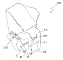
- FIG. 2 shows an external perspective view of one embodiment of the pool hopper PH viewed from the back side.
- a pair of support plates SP vertically separated by a predetermined distance are attached to the back surface of the pool hopper PH in the vertical direction, and two horizontal support bars S1 are provided between the support plates SP. , S2 are mounted vertically separated by a predetermined distance.
- a U-shaped groove 40 in a side view is formed on the upper portion of the bracket 4, and the support rod S1 on the upper portion is hooked and stopped there.
- a vertical surface 41 that restricts the lower support rod S2 from the horizontal direction is formed in the lower portion of the bracket 4. Then, when the upper support rod S1 of the pool hopper PH is hooked on the groove 40 and stopped, the lower support rod S2 abuts the vertical surface 41 and can be hung in a stable state.
- the pool hopper PH of FIG. 2 is provided with a pair of double-opening gates G at its lower end, and these gates G open in opposite directions by flipping up the lever L of the link mechanism LM on the side surface of the hopper body. Then, the articles stored inside are discharged.
- FIG. 3 shows an external perspective view of an embodiment of the drive unit DC taken out from the main body of the combination weighing device W.
- a hanger 1 for suspending the pool hopper PH of FIG. 2 is attached to the front outer wall 2 of the drive unit DU, but in FIG. 3, the hanger 1 is shown to show the opening 6 provided in the front outer wall 2. It is shown in a state of being separated from the front surface of the drive unit DU.
- a rotation lever D1 for opening and closing the gate of the pool hopper PH is provided on the side wall on the right side of the drive unit DU, and a block 11 below the drive unit DU has a hanger for the weighing hopper WH. 10 is attached.
- a turning lever (not shown) for opening and closing the gate of the weighing hopper WH is provided.
- the main drive mechanism of each rotating lever that opens and closes these gates is housed in the drive unit DU.
- a well-known opening/closing lever for swinging the roller R (see FIG. 2) provided on the lever L of the pool hopper PH from above and below is attached to the rotation lever D1 for the pool hopper PH.
- the open/close lever is omitted and only the bolts for attaching the open/close lever are shown.
- a load cell (not shown) on which the load of the weighing hopper WH is loaded is incorporated in the drive unit DU.
- An opening 6 for inserting a tool for adjusting the upper and lower limit positions of the load cell is provided in the front outer wall 2 of the drive unit DU.
- An adjusting nut 60 for adjusting the upper and lower limit positions of the load cell is arranged near the window of the opening 6, and the nut 60 is rotated by a spanner for adjustment.
- the hanger 1 for the pool hopper PH includes a base portion 3 fixed to a front outer wall 2 of the drive unit DU, and a pair of brackets 4 extending upward from both sides of the base portion 3 and separated by a predetermined horizontal distance.
- a pair of arch members 5 that extend in an arch shape to a position protruding from the back surface of the base portion 3 and are also separated by a predetermined distance in the horizontal direction.
- the arch member 5 can be seen only on the right side, but a similar arch member 5 is provided on the left side when facing a predetermined distance.
- the base portion 3 is formed of a metal plate, such as a stainless steel plate, having a size that closes the opening 6.
- a rubber sealing member 7 for sealing the gap when the opening 6 is closed by the base 3. That is, the seal member 7 is provided between the back surface of the base portion 3 and the outer wall 2.
- a stepped portion (not shown) that restricts the deformation of the seal member 7 at a constant compression rate.
- the arch member 5 projects downward from the back surface of the base portion 3 in a substantially vertical direction, and is formed in an arch shape toward the inner wall of the front outer wall 2 and its end portion 51. Touches the inner wall of the front outer wall 2.
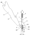
- the minimum distance L1 between the end portion 51 of the arch member 5 and the lower end 32 of the back surface of the base portion 3 is not less than the thickness T of the thickness of the front outer wall 2 plus the thickness of the seal member 7.
- the vertical distance L2 from the end portion 51 of the arch member 5 and the back surface of the base portion 3 is designed to be less than the thickness T.
- the edge portion 61 of the opening 6 can be inserted between the terminal end portion 51 of the arch member 5 and the back surface of the base portion 3.
- the base portion 3 is raised from that state and the rear surface of the base portion 3 is pressed against the front outer wall 2 as shown in FIG. 5
- the end portion 51 of the arch member 5 inserted in the drive unit DU is moved to the outer front surface. Since it is pressed against the inner wall of the wall 2, as a reaction thereof, the back surface of the base portion 3 is in close contact with the surface of the front outer wall 2 while crushing the seal member 7.
- the upper portion of the base portion 3 has two bolt insertion holes 31 in two horizontal positions as shown in FIG.
- Two screw holes 21 are also provided at corresponding locations on the front outer wall 2 that are provided opposite to the front outer wall 2, so that the base portion 3 can be fixed to the front outer wall 2 of the drive unit DU with a bolt (not shown).
- the bolt insertion hole 31 of the present embodiment is provided at a position that does not overlap the opening 6 of the base portion 3 in the direction opposite to the direction in which the arch member 5 extends in the arch shape, and the base portion 3 is formed on the outer wall. Fix firmly to 2.
- a rotation lever (not shown) for opening and closing the gate of the weighing hopper WH is incorporated in the block 11 to which the hanger 10 for the weighing hopper WH is attached.
- the load of the block 11 including the weight of WH is applied to the load cell in the drive unit DU via the seal member such as the diaphragm 12.
- a groove 13 similar to the groove 40 provided in the bracket 4 for the pool hopper PH is provided on the upper portion of the bracket of the hanger 10 for the weighing hopper WH, and above the rear surface of the weighing hopper WH.
- An inclined plate 14 for guiding the supporting rods for the weighing hopper WH, which are the same as the provided horizontal supporting rods S1 and S2 in FIG. 2, to the groove portion 13 is provided.
- the arch member 5 is extended downward from the base portion 3 so that the lower edge portion of the base portion 3 and the arch member 5 sandwich the lower edge portion of the opening portion 6.
- the arch member 5 is extended so as to protrude from the side of the base portion 3, and the side edge of the opening 6 is sandwiched between the side surface of the base portion 3 and the arch member 5 extended to the side. Is also good.
- the base portion 3 is configured to rotate about the right side edge or the left side edge of the opening 6 as a rotation axis like a hinged door. Therefore, it suffices that the arch member 5 extends in an arch shape to a position protruding from the back surface of the base portion.
- the base portion 3 is screwed to the front outer wall 2 with a bolt, but instead of this, a bolt is embedded in the front outer wall 2 and the bolt insertion hole of the base portion 3 is inserted into the bolt.
- the base portion 3 may be tightened and fixed to the front outer wall 2 by means of a retaining nut through 31. In this way, the risk of foreign matter mixing due to the nut falling off can be further reduced.
Landscapes
- Physics & Mathematics (AREA)
- General Physics & Mathematics (AREA)
- Weight Measurement For Supplying Or Discharging Of Specified Amounts Of Material (AREA)
Abstract
装置本体の外側壁(2)に取り付けられるベース部(3)と、前記ベース部(3)の裏面に取り付けられ、該裏面よりはみ出る位置までアーチ状に伸びるアーチ部材(5)と、を備えたハンガー(1)であって、前記外側壁(2)には、前記アーチ部材(5)が挿入可能な開口部(6)が形成され、前記ベース部(3)は、前記開口部(6)を塞ぐ大きさを有して、前記アーチ部材(5)が前記開口部(6)から前記装置本体内に挿入された状態で、前記ベース部(3)で前記開口部(6)が塞がれると、前記アーチ部材(5)の終端部分(51)が前記外側壁(2)の内壁に圧接される構造である。
Description
本発明は、ホッパを吊り下げるホッパ用ハンガーと、該ホッパを複数備えた組合せ計量装置に関する。
組合せ計量装置には、被計量物を一時的に貯留するホッパが複数個搭載されているが、それらのホッパは、日々の清掃に備えて、装置本体に簡単に着脱できるようになっている。具体的には、装置本体の外側壁にホッパ用ハンガーが取り付けられ、そのハンガーにホッパを引っ掛けて止めるようになっている。
一方、前記ハンガーが取り付けられる装置本体の外側壁には、装置内のロードセルの上下の限界位置を調整するための開口部が設けられ、その開口部が、前記ハンガーを支持するベース部によって密閉されるようになっている。そのため、ハンガーのベース部には、前記開口部を密閉するための複数のビス孔が設けられているが、このビス孔を少なくすると、ベース部による密閉が不完全になる。また、ビス孔を多くすると、ベース部の取付工数が増えるとともに、ビスの脱落によって被計量物に異物混入のリスクが高まる。また、被計量物が食品の場合には、食品の粉塵等がビスの頭に積もって衛生上好ましくない。
そうした背景において、組合せ計量装置では、先行技術文献に例示されるような種々のホッパの取付構造が提案されているが、前記開口部を密閉する前記ベース部の取付構造を改善するまでには至っていない。
本発明は、このベース部を固定するビスの取付孔を減らすことのできる新たなホッパ用ハンガーと、そのホッパを搭載した組合せ計量装置を提供することを課題とする。
本発明に係るハンガーは、
装置本体の外側壁に取り付けられるベース部と、
前記ベース部の裏面に取り付けられ、該裏面よりはみ出る位置までアーチ状に伸びるアーチ部材と、を備え、
前記外側壁には、前記アーチ部材が挿入可能な開口部が形成され、
前記ベース部は、前記開口部を塞ぐ大きさを有して、
前記アーチ部材が前記開口部から前記装置本体内に挿入された状態で、前記開口部が前記ベース部で塞がれると、前記アーチ部材の終端部分が前記外側壁の内壁に圧接される構造である。
装置本体の外側壁に取り付けられるベース部と、
前記ベース部の裏面に取り付けられ、該裏面よりはみ出る位置までアーチ状に伸びるアーチ部材と、を備え、
前記外側壁には、前記アーチ部材が挿入可能な開口部が形成され、
前記ベース部は、前記開口部を塞ぐ大きさを有して、
前記アーチ部材が前記開口部から前記装置本体内に挿入された状態で、前記開口部が前記ベース部で塞がれると、前記アーチ部材の終端部分が前記外側壁の内壁に圧接される構造である。
使用に際しては、アーチ部材を開口部から装置本体内に挿入した後、ベース部で開口部を塞ぐように押し付ける。すると、アーチ部材の終端部分が開口部から離れた外側壁の内壁に圧接されるから、その反作用として、ベース部のアーチ部材と重なる部分が外側壁に押し付けられる。その結果、ベース部のアーチ部材と重なる部分をボルト等で外側壁に固定しなくても、ベース部のアーチ部材と重ならない部分をボルトでネジ止めするだけで、ベース部を開口部に密着固定させることができる。したがって、ベース部を取り付けるボルトの数を減らすことができる。
また、前記開口部は、装置本体内に工具が挿入される窓であることを特徴とする。
装置本体内には、例えば質量センサであるロードセルが組み込まれるが、そのロードセルには、計量ホッパと、そのゲート開閉機構とを含めた風袋荷重が負荷されるので、そうした風袋荷重を負荷させた状態で、ロードセルの上下方向の限界位置を調整する必要がある。この開口部は、そうした調整を行うために、スパナ等の工具が挿入できる窓として形成され、その窓際に、ロードセルの限界位置調整機構が臨まされている。
また、前記ベース部の裏面と、前記外側壁との間には、前記開口部をシールするためのシール部材が設けられることを特徴とする。
これにより、ベース部で開口部を塞いだときに、それらの間がシール部材によってシールされるから、装置本体内を防水仕様にすることができる。
また、前記アーチ部材の終端部分と前記ベース部の裏面の下端との最小距離が前記外側壁の肉厚に前記シール部材の肉厚を加えた厚さ以上であり、かつ、前記アーチ部材の終端部分と前記ベース部の裏面からの垂直距離が前記外側壁の肉厚に前記シール部材の肉厚を加えた厚さ未満であることを特徴とする。
これにより、アーチ部材の終端部分とベース部の裏面との間に開口部の縁を挿入することができる。その状態からベース部の裏面を開口部に押し当てて開口部を塞ぐと、装置本体内に挿入されたアーチ部材の終端部分が外側壁の内壁に圧接されるから、その反作用として、ベース部の裏面がシール部材を押し潰しながら外側壁の表面に密着する。
また、ベース部の裏面を外側壁に沿わせた状態で、前記アーチ部材を前記外側壁の開口部に挿入できる場合は、前記アーチ部材の終端部分と前記ベース部の裏面との距離が、前記外側壁の肉厚以上であり、かつ、該肉厚に前記シール部材の肉厚を加えた厚さ未満であれば、ベース部の裏面を開口部に押し当てて開口部を塞ぐと、装置本体内に挿入されたアーチ部材の終端部分が外側壁の内壁に圧接するから、前述同様にベース部の裏面をシール部材を介して外側壁の表面に密着させることができる。
これにより、シール部材によってベース部と開口部との間が完全にシールされる。
また、ベース部の裏面を外側壁に沿わせた状態で、前記アーチ部材を前記外側壁の開口部に挿入できる場合は、前記アーチ部材の終端部分と前記ベース部の裏面との距離が、前記外側壁の肉厚以上であり、かつ、該肉厚に前記シール部材の肉厚を加えた厚さ未満であれば、ベース部の裏面を開口部に押し当てて開口部を塞ぐと、装置本体内に挿入されたアーチ部材の終端部分が外側壁の内壁に圧接するから、前述同様にベース部の裏面をシール部材を介して外側壁の表面に密着させることができる。
これにより、シール部材によってベース部と開口部との間が完全にシールされる。
また、アーチ部材がアーチ状に伸びる方向とは逆方向の、前記ベース部の前記開口部と重ならない位置には、前記ベース部を前記外側壁に密着固定するボルト挿通孔が設けられていることを特徴とする。
この場合のボルト挿通孔は、少なくとも1か所、好ましくは等距離離れた2か所に設けておけば足りる。これにより、ボルトの使用本数を減らすことができる。
また、前記装置が、複数のホッパが搭載された組合せ計量装置であって、前記ベース部の表側には、前記ホッパを引っ掛けて吊り下げるブラケットが設けられていることを特徴とする。
ここでの表側は、開口部を塞ぐベース部の裏面とは反対側の面である。したがって、ホッパは、ベース部の表側に設けられたブラケットに引っ掛けて吊り下げることができる。
また、前記装置本体の外側壁が、前記ホッパのゲートを開閉させる駆動ユニットの前面外側壁であることを特徴とする。
これにより、駆動ユニットの前面外側壁にホッパを着脱自在に装着することができるから、組合せ計量装置本体に対するホッパの着脱作業が容易になる。また、駆動ユニットの前面外側壁に開口部を設けることができるから、その開口部から駆動ユニット内をメンテナンスすることが可能になる。
さらに、前記ホッパが、上流から供給される物品を一時的に保持して、下方の計量ホッパへ前記物品を排出するプールホッパであることを特徴とする。
これにより、計量ホッパの上部に計量ホッパの質量を検出するロードセルを配置した場合に、前記開口部からロードセルの上下の限界位置を調整することができるから、装置を組み立てた後のメンテナンス性を向上させることができる。
本発明によれば、ホッパ用のハンガーを固定するためのボルトの使用本数を減らすことができるから、ボルトの取付工数を減らして、生産性を高めることができるとともに、ボルトの脱落による異物混入リスクを低減させることができる。
以下、図面を参照しながら、本発明の一実施形態を説明する。なお、以下に示す実施形態は、本発明の技術的範囲を限定するものではない。
図1は、本発明に係る組合せ計量装置の一実施形態の外観斜視図を示す。この図において、組合せ計量装置Wは、装置上部の分散供給装置DSと、その下段に円周状に配列された複数のプールホッパPHと、さらにその下段に、各プールホッパPHに対応させて配列された複数の計量ホッパWHと、分散供給装置DSの下部に配置されて、プールホッパPHと計量ホッパWHの各ゲートを個別に開閉させる駆動ユニットDU(図3参照)と、各計量ホッパWHから排出された物品を集合させて下端排出口から所定質量に組合された物品を排出する集合シュートCSと、これらを支持するベース部Bとを備えている。
装置上部に配置される分散供給装置DSは、中央部に位置して、上方から供給される物品を周囲へ分散させる円錐形状の分散テーブルDTと、分散テーブルDTの外周に放射状に配列されて、分散テーブルDTから送り出された物品をさらに外周へと搬送する複数の放射フィーダRFとを備えている。
放射フィーダRFは、分散テーブルDTから搬送されてきた物品をプールホッパPHへ所定量ずつ送り出すもので、周知構成の放射トラフRTと、その放射トラフRTを所定時間振動させる図示しない電磁バイブレータとで構成されている。また、隣接する各放射トラフRTは、一方の側壁が他方の放射トラフRTの側壁に非接触でオーバーラップして、各放射トラフRTが連鎖状に繋がった状態で全体が一つの受け皿となるように構成されている。
各放射フィーダRFの先端部には、プールホッパPHが円周状に配列されて、放射フィーダRFから供給される物品を対応する各プールホッパPHで一時的に蓄えるようになっている。また、分散供給装置DSの下部には、プールホッパPHと計量ホッパWHを個別に駆動する後述の駆動ユニットDCが収められている。
図2は、プールホッパPHを背面側から見た一実施形態の外観斜視図を示す。この図2において、プールホッパPHの背面には、水平方向に所定距離離れた一対の支持板SPが上下方向に取り付けられ、それらの支持板SPの間には、水平な2本の支持棒S1、S2が上下に所定距離離して取り付けられている。
このプールホッパPHを図3に示すハンガー1に引っ掛けるときは、プールホッパPHの背面に設けられた各支持棒S1,S2を図3のハンガー1のブラケット4に引っ掛けて吊り下げる。
具体的には、ブラケット4の上部には、側面視U字状の溝部40が形成され、そこに上部の支持棒S1を引っ掛けて止める。また、ブラケット4の下部には、下部の支持棒S2を水平方向から規制する鉛直面41が形成されている。そして、プールホッパPHの上部支持棒S1を溝部40に引っ掛けて止めると、下部支持棒S2が鉛直面41に当接して、安定した状態で吊り下げられるようになっている。
なお、図2のプールホッパPHは、下端部に一対の両開きゲートGが設けられ、それらのゲートGは、ホッパ本体側面のリンク機構LMのレバーLを上方に跳ね上げれば、互いに反対方向に開いて、内部に収納された物品を排出するようになっている。
図3は、組合せ計量装置Wの本体から取り出した駆動ユニットDCの一実施形態の外観斜視図を示す。この駆動ユニットDUの前面外側壁2には、図2のプールホッパPHを吊り下げるハンガー1が取り付けられるが、図3では、前面外側壁2に設けられた開口部6を見せるため、ハンガー1を駆動ユニットDUの前面から分離した状態で示している。
この図3において、駆動ユニットDUの、向かって右側の側壁には、プールホッパPHのゲートを開閉させる回動レバーD1が設けられ、駆動ユニットDU下部のブロック11には、計量ホッパWH用のハンガー10が取り付けられている。また、このブロック11の、向かって左側の側面には、計量ホッパWHのゲートを開閉させる、図示しない回動レバーが設けられている。これらのゲートを開閉させる各回動レバーの主要な駆動機構は、駆動ユニットDU内に収納されている。
なお、プールホッパPH用の回動レバーD1には、プールホッパPHの前記レバーLに設けられたコロR(図2参照)を上下から挟んで揺動させる周知の開閉レバーが取り付けられるが、図3では、その開閉レバーを省略して、それを取り付けるボルトだけを示している。
なお、プールホッパPH用の回動レバーD1には、プールホッパPHの前記レバーLに設けられたコロR(図2参照)を上下から挟んで揺動させる周知の開閉レバーが取り付けられるが、図3では、その開閉レバーを省略して、それを取り付けるボルトだけを示している。
また、駆動ユニットDU内には、前述の駆動機構の他に、計量ホッパWHの荷重が負荷される図示しないロードセルが組み込まれている。そして、ロードセルの上下の限界位置を調整するための工具挿入用の開口部6が、駆動ユニットDUの前面外側壁2に設けられている。なお、開口部6の窓際には、ロードセルの上下の限界位置を調整する調整用ナット60が配置され、そのナット60をスパナで回して調整するようになっている。
プールホッパPH用のハンガー1は、駆動ユニットDUの前面外側壁2に固定されるベース部3と、該ベース部3の両サイドから上方に伸びる、水平方向に所定距離離れた一対のブラケット4と、前記ベース部3の裏面からはみ出る位置までアーチ状に伸びる、同じく水平方向に所定距離離れた一対のアーチ部材5と、を備えている。なお、図3では、アーチ部材5は、右側しか見えないが、所定距離離れた、向かって左側にも同様なアーチ部材5が設けられている。
前記ベース部3は、前記開口部6を塞ぐ大きさの金属板、たとえばステンレス板で形成されている。この開口部6の周囲には、ベース部3で開口部6を塞いだときの隙間をシールするゴム製のシール部材7が設けられている。すなわち、シール部材7は、ベース部3の裏面と、外側壁2との間に設けられている。また、このシール部材7で囲まれた開口部6の周囲には、一定の圧縮率でシール部材7の変形を規制する、図示しない段差部が設けられている。
アーチ部材5は、図4に示すように、ベース部3の裏面から略垂直に方向に下向きに突出するとともに、前面外側壁2の内壁に向けてアーチ状に形成されており、その終端部分51は、前面外側壁2の内壁に当接するようになっている。
具体的には、アーチ部材5の終端部分51とベース部3の裏面の下端32との最小距離L1は、前面外側壁2の肉厚にシール部材7の肉厚を加えた厚さT以上であって、かつ、アーチ部材5の終端部分51と、ベース部3の裏面からの垂直距離L2は、前記厚さT未満となるように設計されている。
これにより、アーチ部材5を駆動ユニットDU内に挿入すると、アーチ部材5の終端部分51とベース部3の裏面との間に開口部6の縁部61を挿入することができる。その状態からベース部3を起こして、図5に示すように、ベース部3の裏面を前面外側壁2に押し当てると、駆動ユニットDU内に挿入されたアーチ部材5の終端部分51が前面外側壁2の内壁に圧接されるから、その反作用として、ベース部3の裏面がシール部材7を押し潰しながら、前面外側壁2の表面に密着する。
その際、ベース部3の上部を駆動ユニットDUの前面外側壁2に強く押し付ける必要があるから、ベース部3の上部には、図3に示すように、ボルト挿通孔31が水平方向に2カ所設けられ、それと対向する前面外側壁2の対応箇所にも、ネジ穴21が2カ所設けられて、図示しないボルトでもってベース部3を駆動ユニットDUの前面外側壁2に固定できるようになっている。
このように、本実施形態のボルト挿通孔31は、アーチ部材5がアーチ状に伸びる方向とは逆方向の、ベース部3の開口部6と重ならない位置に設けられ、ベース部3を外側壁2に密着固定する。
このように、本実施形態のボルト挿通孔31は、アーチ部材5がアーチ状に伸びる方向とは逆方向の、ベース部3の開口部6と重ならない位置に設けられ、ベース部3を外側壁2に密着固定する。
また、図3において、計量ホッパWH用のハンガー10が取り付けられたブロック11には、計量ホッパWHのゲートを開閉させる図示しない回動レバーが組み込まれるが、その回動レバーの駆動機構と計量ホッパWHの重量とを合わせたブロック11の荷重が、ダイヤフラム12等のシール部材を介して駆動ユニットDU内のロードセルに負荷されるようになっている。
なお、計量ホッパWH用のハンガー10のブラケットの上部には、プールホッパPH用のブラケット4に設けられた溝部40と同様な溝部13が設けられ、さらにその上方には、計量ホッパWHの背面に設けられた、図2の水平支持棒S1、S2と同様な計量ホッパWH用の支持棒を溝部13に案内する傾斜板14が設けられている。これにより、計量ホッパWHの背面に設けられた支持棒を傾斜板14に乗せるだけで、支持棒が溝部13に滑落して、計量ホッパWHがハンガー10のブラケットに吊り下げられるようになっている。
以上、本発明の一実施形態を説明したが、本発明は、これに限定されるものではなく、その他の構成も採用可能である。例えばこの実施形態では、図4に示すように、アーチ部材5をベース部3から下方に伸ばして、ベース部3の下端部とアーチ部材5とで、開口部6の下側縁部を挟むようにしたが、このアーチ部材5をベース部3の側方からはみ出すように伸ばして、ベース部3の側面と、側方に伸ばしたアーチ部材5とで、開口部6の側縁部を挟むようにしても良い。この場合には、ベース部3が開き戸のように、開口部6の右側縁部、あるいは、左側縁部を回転軸として回動する構成となる。したがって、アーチ部材5は、ベース部の裏面からはみ出る位置までアーチ状に伸びていればよい。
また、上記実施形態では、ボルトでベース部3を前面外側壁2にネジ止めするようにしたが、これに代えて、前面外側壁2にボルトを埋め込み、そのボルトにベース部3のボルト挿通孔31を通して、抜け止め防止ナットでベース部3を前面外側壁2に締め付けて固定するようにしてもよい。こうすれば、ナットの脱落による異物混入のリスクをさらに低減することができる。
1 ハンガー
2 外側壁(前面外側壁)
3 ベース部
4 ブラケット
5 アーチ部材
6 開口部
7 シール部材
20 内壁
31 ボルト挿通孔
32 ベース部の裏面の下端
51 アーチ部材の終端部分
PH プールホッパ
WH 計量ホッパ
DU 駆動ユニット
W 組合せ計量装置
2 外側壁(前面外側壁)
3 ベース部
4 ブラケット
5 アーチ部材
6 開口部
7 シール部材
20 内壁
31 ボルト挿通孔
32 ベース部の裏面の下端
51 アーチ部材の終端部分
PH プールホッパ
WH 計量ホッパ
DU 駆動ユニット
W 組合せ計量装置
Claims (8)
- 装置本体の外側壁に取り付けられるベース部と、
前記ベース部の裏面に取り付けられ、該裏面よりはみ出る位置までアーチ状に伸びるアーチ部材と、を備え、
前記外側壁には、前記アーチ部材が挿入可能な開口部が形成され、
前記ベース部は、前記開口部を塞ぐ大きさを有して、
前記アーチ部材が前記開口部から前記装置本体内に挿入された状態で、前記ベース部で前記開口部が塞がれると、前記アーチ部材の終端部分が前記外側壁の内壁に圧接される構造であるハンガー。 - 前記開口部は、前記装置本体内に工具が挿入される窓である、請求項1に記載のハンガー。
- 前記ベース部の裏面と、前記外側壁との間には、前記開口部をシールするためのシール部材が設けられる、請求項1又は2に記載のハンガー。
- 前記アーチ部材の終端部分と前記ベース部の裏面の下端との最小距離が、前記外側壁の肉厚に前記シール部材の肉厚を加えた厚さ以上であり、かつ、前記アーチ部材の終端部分と前記ベース部の裏面からの垂直距離が、前記外側壁の肉厚に前記シール部材の肉厚を加えた厚さ未満である請求項3に記載のハンガー。
- 前記アーチ部材がアーチ状に伸びる方向とは逆方向の、前記ベース部の前記開口部と重ならない位置には、前記ベース部を前記外側壁に密着固定するボルト挿通孔が設けられている、請求項1~4の何れか1項に記載のハンガー。
- 前記装置が、複数のホッパが搭載された組合せ計量装置であって、前記ベース部の表側には、前記ホッパを引っ掛けて吊り下げるブラケットが設けられている、請求項1~5の何れか1項に記載のハンガー。
- 前記装置本体の外側壁が、前記ホッパのゲートを開閉させる駆動ユニットの前面外側壁である、請求項6に記載のハンガー。
- 前記ホッパが、上流から供給される物品を一時的に保持して、下方の計量ホッパへ前記物品を排出するプールホッパである請求項6又は7に記載の組合せ計量装置。
Applications Claiming Priority (2)
| Application Number | Priority Date | Filing Date | Title |
|---|---|---|---|
| JP2019-000207U | 2019-01-24 | ||
| JP2019000207U JP3221867U (ja) | 2019-01-24 | 2019-01-24 | ハンガーおよび組合せ計量装置 |
Publications (1)
| Publication Number | Publication Date |
|---|---|
| WO2020152957A1 true WO2020152957A1 (ja) | 2020-07-30 |
Family
ID=67003806
Family Applications (1)
| Application Number | Title | Priority Date | Filing Date |
|---|---|---|---|
| PCT/JP2019/045039 Ceased WO2020152957A1 (ja) | 2019-01-24 | 2019-11-18 | ハンガーおよび組合せ計量装置 |
Country Status (2)
| Country | Link |
|---|---|
| JP (1) | JP3221867U (ja) |
| WO (1) | WO2020152957A1 (ja) |
Families Citing this family (1)
| Publication number | Priority date | Publication date | Assignee | Title |
|---|---|---|---|---|
| JP6982923B2 (ja) * | 2019-09-26 | 2021-12-17 | 株式会社イシダ | 物品滞留装置及び支持体 |
Citations (4)
| Publication number | Priority date | Publication date | Assignee | Title |
|---|---|---|---|---|
| US4662462A (en) * | 1986-04-17 | 1987-05-05 | Ishida Scales Manufacturing Company, Ltd. | Compact combinational weighing system |
| JP2003042830A (ja) * | 2001-07-27 | 2003-02-13 | Ishida Co Ltd | ホッパ及びそれを備えた計量装置 |
| JP2010281745A (ja) * | 2009-06-05 | 2010-12-16 | Ishida Co Ltd | 組合せ計量装置 |
| JP2013096738A (ja) * | 2011-10-28 | 2013-05-20 | Yamato Scale Co Ltd | ホッパの開閉機構 |
-
2019
- 2019-01-24 JP JP2019000207U patent/JP3221867U/ja not_active Expired - Fee Related
- 2019-11-18 WO PCT/JP2019/045039 patent/WO2020152957A1/ja not_active Ceased
Patent Citations (4)
| Publication number | Priority date | Publication date | Assignee | Title |
|---|---|---|---|---|
| US4662462A (en) * | 1986-04-17 | 1987-05-05 | Ishida Scales Manufacturing Company, Ltd. | Compact combinational weighing system |
| JP2003042830A (ja) * | 2001-07-27 | 2003-02-13 | Ishida Co Ltd | ホッパ及びそれを備えた計量装置 |
| JP2010281745A (ja) * | 2009-06-05 | 2010-12-16 | Ishida Co Ltd | 組合せ計量装置 |
| JP2013096738A (ja) * | 2011-10-28 | 2013-05-20 | Yamato Scale Co Ltd | ホッパの開閉機構 |
Also Published As
| Publication number | Publication date |
|---|---|
| JP3221867U (ja) | 2019-06-27 |
Similar Documents
| Publication | Publication Date | Title |
|---|---|---|
| JP7403934B2 (ja) | ホッパ取付け構造及びそれを備えた計量装置 | |
| US9234787B2 (en) | Actuator mount for a combination weigher | |
| US6188029B1 (en) | Weighing apparatus having improved hopper detachability | |
| US10782180B2 (en) | Hopper and combination weighing device | |
| JP3221867U (ja) | ハンガーおよび組合せ計量装置 | |
| JP6982923B2 (ja) | 物品滞留装置及び支持体 | |
| JP6305835B2 (ja) | 物品規制装置及びこれを備える組合せ秤 | |
| CN109632063A (zh) | 一种易调节、易拆装的组合秤 | |
| CN216511533U (zh) | 一种新型电磁振动给料机 | |
| JP5858729B2 (ja) | ホッパの開閉機構 | |
| CN209565750U (zh) | 一种应用于铰链安装座部分的组装设备 | |
| CN108557124B (zh) | 一种吨包机 | |
| EP3543662B1 (en) | Combination weighing apparatus having a conveying device | |
| CN2906838Y (zh) | 活动式平板电视壁挂架 | |
| CN205872610U (zh) | 一种应用于称重包装设备的物料暂存器 | |
| CN214191302U (zh) | 一种改进型皮带输送机用防护导料槽 | |
| CN206456630U (zh) | 一种密封料斗驱动结构 | |
| CN212355380U (zh) | 一种转轴调节结构 | |
| EP4700339A1 (en) | Waterproof structure of combination weighing device | |
| CN108545242B (zh) | 一种食品自动定量称重包装机 | |
| CN219031071U (zh) | 一种皮带机输入端下料口防堵料仓门 | |
| CN207060587U (zh) | 一种水产包装机的输料机构 | |
| CN222318198U (zh) | 一种物料自动计量称 | |
| CN214933538U (zh) | 一种五金件自动配件机 | |
| JP7692668B2 (ja) | 組合せ秤 |
Legal Events
| Date | Code | Title | Description |
|---|---|---|---|
| 121 | Ep: the epo has been informed by wipo that ep was designated in this application |
Ref document number: 19911709 Country of ref document: EP Kind code of ref document: A1 |
|
| NENP | Non-entry into the national phase |
Ref country code: DE |
|
| 122 | Ep: pct application non-entry in european phase |
Ref document number: 19911709 Country of ref document: EP Kind code of ref document: A1 |