WO2020149415A1 - 駆動ユニット及び画像生成システム - Google Patents
駆動ユニット及び画像生成システム Download PDFInfo
- Publication number
- WO2020149415A1 WO2020149415A1 PCT/JP2020/001600 JP2020001600W WO2020149415A1 WO 2020149415 A1 WO2020149415 A1 WO 2020149415A1 JP 2020001600 W JP2020001600 W JP 2020001600W WO 2020149415 A1 WO2020149415 A1 WO 2020149415A1
- Authority
- WO
- WIPO (PCT)
- Prior art keywords
- drive unit
- imaging core
- unit
- catheter
- mdu
- Prior art date
- Legal status (The legal status is an assumption and is not a legal conclusion. Google has not performed a legal analysis and makes no representation as to the accuracy of the status listed.)
- Ceased
Links
Images


Classifications
-
- A—HUMAN NECESSITIES
- A61—MEDICAL OR VETERINARY SCIENCE; HYGIENE
- A61B—DIAGNOSIS; SURGERY; IDENTIFICATION
- A61B8/00—Diagnosis using ultrasonic, sonic or infrasonic waves
- A61B8/12—Diagnosis using ultrasonic, sonic or infrasonic waves in body cavities or body tracts, e.g. by using catheters
Definitions
- the present invention relates to a drive unit and an image generation system.
- an intravascular ultrasound diagnostic device IVUS: IntraVascular UltraSound
- an optical coherence tomography diagnostic OFDI: Optical Frequency Domain Imaging
- IVUS can be used, for example, when performing percutaneous coronary intervention (PCI) for chronic total occlusion (CTO) lesion.
- PCI percutaneous coronary intervention
- CTO chronic total occlusion
- the doctor performs a procedure using the image generated by IVUS in order to pass the wire through the occlusion site of the blood vessel.
- the doctor identifies the position of the intimal blood vessel (intimal) and the orientation and position of the wire to be operated by observing the two-dimensional image generated by IVUS, and based on the identified positional relationship, Imagine a three-dimensional positional relationship in my head.
- the doctor When actually performing the procedure, the doctor, while looking at the angiography (Angio) image, imagines a position where the three-dimensional positional relationship imaged based on the image generated by IVUS corresponds to the Angio image. , Operate the wire.
- Angio angiography
- the procedure is performed while imagining the three-dimensional positional relationship between the intima of the blood vessel and the wire, and therefore the degree of difficulty for the doctor is high and the procedure tends to take time.
- the success or failure of the procedure is likely to increase depending on the skill of the doctor.
- OFDI can be used, for example, when performing a procedure of placing a stent on a bifurcation lesion of a blood vessel. Specifically, for example, a doctor performs a procedure while checking a three-dimensional image generated by OFDI in order to pass a wire to a desired position at a branch point of a blood vessel of a patient.
- OFDI uses optical properties to perform imaging, it is necessary to remove blood in blood vessels when performing imaging. Therefore, at the time of imaging, a contrast agent is flowed through the blood vessel to perform imaging, and then the doctor confirms the three-dimensional image generated based on the captured image and performs the wire operation.
- the imaging by the OFDI and the wire operation by the doctor are sequentially repeated until the wire passes through the desired position.
- the three-dimensional image confirmed by the doctor does not always match the current position of the wire. That is, the real-time property is likely to be impaired.
- An object of the present invention is to provide a drive unit and an image generation system that can continuously update a captured image of a patient during a procedure by a doctor or the like.
- the drive unit in a state in which the imaging core is connected to the connecting portion capable of connecting an imaging core that is housed in a catheter and has an ultrasonic wave transmitting/receiving portion at the tip, A reciprocating drive unit that reciprocates the imaging core continuously along the longitudinal direction of the catheter.
- the reciprocating drive unit reciprocates the imaging core by a piston crank mechanism.
- the reciprocating drive unit is connected to the crank arm that makes a rotary motion about a crankshaft, the crank arm at one end side, and the extension of the cylinder at the other end side.
- a connecting rod connected to a piston that is displaceable along the direction, and the connecting rod is configured such that a connecting position to the crank arm on the one end side is variable.
- the reciprocating drive unit reciprocates the imaging core at a speed of 15 feet per second or more.
- a drive unit as one embodiment of the present invention in a state in which the imaging core is connected to the connection portion, a drive shaft included in the imaging core, a rotation drive unit that rotates about the longitudinal direction of the imaging core as an axis. Further prepare.
- the driving unit as one embodiment of the present invention further includes an electric signal transmitting/receiving unit that transmits/receives an electric signal to/from the ultrasonic transmitting/receiving unit in a state where the driving unit is electrically connected to the ultrasonic transmitting/receiving unit. ..
- the drive unit as one embodiment of the present invention is a linear drive unit that displaces the imaging core from the distal end side to the rear end side along the longitudinal direction of the catheter in a state where the imaging core is connected to the connection unit. Is further provided.
- An image generation system as a second aspect of the present invention includes the drive unit described above and an information processing device that generates a captured image based on an ultrasonic signal received by the ultrasonic transmission/reception unit.
- the information processing device based on a new ultrasonic signal received by the ultrasonic transmission/reception unit according to the reciprocating motion of the imaging core, the generated imaging Update the image.
- the information processing device generates a three-dimensional captured image.
- a drive unit and an image generation system capable of continuously updating a captured image of a patient during a procedure by a doctor or the like.
- FIG. 1 is a schematic diagram showing an example of the configuration of an image generation system 1 according to the first embodiment.
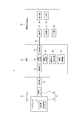
- FIG. 2 is a functional block diagram showing an example of a schematic configuration of the image generation system 1 of FIG.
- the image generation system 1 includes a catheter 10, a motor drive unit (hereinafter, also simply referred to as “MDU”) 20, and an information processing device 30.
- the MDU 20 in this embodiment functions as a drive unit in the present invention. That is, the MDU 20 shows an example in which the drive unit is embodied.
- the image generation system 1 is used with the catheter 10 connected to the MDU 20. Further, the image generation system 1 is used in a state where the MDU 20 and the information processing device 30 are connected by wire or wirelessly so that they can communicate with each other. For example, as shown in FIG. 1, the MDU 20 and the information processing device 30 are connected by a cable 40 that accommodates signal lines and the like. The MDU 20 and the information processing device 30 may be wirelessly connected by a network such as a LAN (Local Area Network).
- LAN Local Area Network
- the image generation system 1 is used, for example, when a doctor performs a procedure to capture an image of a specific part inside the patient's body.
- the specific location is, for example, a location to be diagnosed, and specifically, may be a location in a blood vessel, for example.
- the catheter 10 is inserted into a specific location inside the patient's body, and the imaging core 11 housed in the catheter 10 collects information regarding the three-dimensional structure of the specific location. Then, the signal of the collected information is transmitted from the imaging core 11 to the MDU 20.
- the MDU 20 transmits the signal received from the imaging core 11 to the information processing device 30.
- the information processing device 30 generates a three-dimensional image of a specific location based on the received signal and displays it on the display unit 34 such as a display. The doctor can perform the procedure while looking at the three-dimensional image displayed on the display unit 34.
- the catheter 10 is directly inserted into the patient's body.
- the catheter 10 is movable in the longitudinal direction.
- the catheter 10 houses the imaging core 11 inside.
- the imaging core 11 is housed in the catheter 10 so as to be rotatable about the longitudinal direction.
- An ultrasonic transmission/reception unit 12 is provided at the tip of the imaging core 11.
- the imaging core 11 emits an ultrasonic wave toward the vascular tissue of the patient from the ultrasonic wave transmitting/receiving unit 12 and receives a reflected wave of the emitted ultrasonic wave to obtain a three-dimensional structure of a specific part in the patient's body.
- the information about is collected as an ultrasonic signal.
- the ultrasonic transmitter/receiver 12 is housed in a housing 13.
- a drive shaft 14 is connected to the housing 13 for transmitting rotational movement about the longitudinal direction of the imaging core 11 from the MDU 20 and reciprocating movement to be described later when the catheter 10 is connected to the MDU 20.
- the imaging core 11 is composed of the housing 13 in which the ultrasonic transmission/reception unit 12 is provided and the drive shaft 14.
- the catheter 10 has a connecting portion 15 at the rear end for connecting the catheter 10 to the MDU 20.
- the connecting portion 15 of the catheter 10 By connecting the connecting portion 15 of the catheter 10 to the connecting portion 25 of the MDU 20, the catheter 10 is connected to the MDU 20.
- the MDU 20 controls the operation of the imaging core 11 of the catheter 10 and also functions as a relay device between the catheter 10 and the information processing device 30.
- the MDU 20 includes a connecting portion 25 connected to the connecting portion 15 of the catheter 10.
- the connecting portion 25 may be composed of, for example, a connecting connector.
- the connection portion 25 may be configured by a connectable mechanism or component other than the connection connector.
- the catheter 10 and the MDU 20 are mechanically and electrically connected to each other.
- mechanically connecting the catheter 10 and the MDU 20 it becomes possible to drive the imaging core 11 under the control of the MDU 20, which will be described later.
- electrically connecting the catheter 10 and the MDU 20 it becomes possible to transmit and receive signals between the catheter 10 and the MDU 20.
- the MDU 20 functions as a drive unit that operates the imaging core 11 when connected to the catheter 10.
- the MDU 20 includes a reciprocating drive unit 21.
- the reciprocating drive unit 21 continuously reciprocates the imaging core 11 along the longitudinal direction of the catheter 10 when the MDU 20 is connected to the catheter 10.
- the reciprocating drive unit 21 may include, for example, a piston crank mechanism.
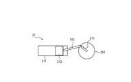
- FIG. 3 is a schematic diagram showing an example of a specific configuration of the reciprocating drive unit 21 of FIG. 2, and is a schematic diagram showing a specific example of the reciprocating drive unit 21 when it is configured by a piston crank mechanism.
- the reciprocating drive unit 21 includes a cylinder 211, a piston 212, a connecting rod 213, and a crankshaft 214 when the reciprocating drive unit 21 is configured by a piston crank mechanism as shown in FIG. 3, for example.
- the crankshaft 214 includes a crank arm 215.
- the crank arm 215 has one end located on the crankshaft side and the other end located radially outside the crankshaft 214.
- the crank arm 215 makes a rotational movement about the crank shaft.
- One end of the connecting rod 213 is connected to the other end of the crank arm 215.
- the other end of the connecting rod 213 is connected to the piston 212.
- the piston 212 is arranged inside the cylinder 211 so that it can be displaced along the extending direction of the cylinder 211.
- the crankshaft 214 rotates, the rotational movement of the crankshaft 214 is converted into a linear movement in the extending direction of the cylinder 211 via the crank arm 215 and the connecting rod 213. In this way, the rotation of the crankshaft 214 causes the piston 212 to reciprocate in the extending direction of the cylinder 211.
- the piston 212 When the catheter 10 and the MDU 20 are connected, the piston 212 is mechanically connected to the drive shaft 14 of the imaging core 11, whereby the linear motion (that is, reciprocating motion) of the piston 212 is transmitted to the imaging core 11. .. This allows the imaging core 11 to reciprocate. With the reciprocating motion of the imaging core 11, the ultrasonic wave transmitting/receiving unit 12 in the housing 13 connected to the drive shaft 14 reciprocates along the longitudinal direction of the catheter 10.
- the reciprocating drive unit 21 preferably reciprocates the imaging core 11 at a speed of 15 feet per second or more.
- the ultrasonic transmission/reception unit 12 can scan a specific area over a predetermined range. Specifically, the ultrasonic transmission/reception unit 12 can perform scanning over the displacement length of the reciprocating motion.
- the displacement length of the reciprocating motion is determined according to the length of the crank arm 215.
- the one end side of the connecting rod 213 connected to the crank arm 215 may be configured so that the position connected to the crank arm 215 is variable. That is, the connecting rod 213 may be configured such that the connection position to the crank arm 215 on the one end side is variable.
- the displacement length may be changeable within a range of 1 to 20 mm, for example. However, the changeable range of the displacement length is not limited to this, and may be appropriately set to a desired range in the image generation unit 1.
- the reciprocating drive unit 21 does not necessarily have to include the piston crank mechanism.
- the reciprocating drive unit 21 may be configured by any mechanism capable of reciprocating the imaging core 11.
- the MDU 20 further includes a rotation driving unit 22, an electric signal transmitting/receiving unit 23, a communication unit 24, and a linear driving unit 26.
- the rotation drive unit 22 rotates the imaging core 11 while the catheter 10 is connected to the MDU 20. Specifically, the rotation drive unit 22 causes the drive shaft of the imaging core 11 to rotate about the longitudinal direction of the imaging core 11 as an axis.
- the rotation driving unit 22 can rotate the imaging core 11 by driving a built-in motor, for example.
- the ultrasonic transmission/reception unit 12 performs rotational movement about the longitudinal direction.
- the ultrasonic transmission/reception unit 12 can perform scanning along a circumferential direction of the imaging core 11 with respect to a specific portion inside the patient's body.
- the electric signal transmission/reception unit 23 transmits/receives an electric signal to/from the ultrasonic transmission/reception unit 12 of the catheter 10 while the catheter 10 is connected to the MDU 20.
- the electric signal transmitting/receiving unit 23 transmits, to the ultrasonic wave transmitting/receiving unit 12, an electric signal that starts and stops the collection of information regarding the three-dimensional structure.
- the electrical signal transmission/reception unit 23 can transmit various electrical signals based on, for example, an input operation on various buttons or switches provided on the MDU 20 or based on a signal received from the information processing device 30.
- the electric signal transmitting/receiving unit 23 receives an electric signal corresponding to the ultrasonic signal as the collection result of the information on the three-dimensional structure from the ultrasonic transmitting/receiving unit 12.
- the electric signal transmission/reception unit 23 may not necessarily be included in the MDU 20 and may be included in the information processing device 30, for example. ..
- the linear drive unit 26 executes the pullback operation of the imaging core 11.
- the linear drive unit 26 includes, for example, a motor, and drives the motor to displace the imaging core 11 from the front end side to the rear end side along the longitudinal direction of the catheter 10.
- the linear driving unit 26 can displace the imaging core 11 at a speed of 0.5 mm/s to 10 mm/s.
- the linear driving unit 26 can displace the imaging core 11 by a distance longer than the displacement length of the reciprocating driving unit 21.
- the linear drive unit 26 can displace the imaging core 11 by 150 mm, for example.
- the distance for displacing the linear drive unit 26 is not limited to this, and may be appropriately set within a desired range in the image generation unit 1.
- the imaging core 11 can execute the first operation and the second operation.
- the imaging core 11 performs either the first operation or the second operation based on an input operation on various buttons or switches provided in the MDU 20, or based on a signal received from the information processing device 30, for example. Execute.
- the first operation is an operation executed by the reciprocating drive unit 21 and the rotation drive unit 22.
- the first operation is an operation in which the imaging core 11 makes a reciprocating motion by being driven by the reciprocating driving unit 21 and makes a rotational motion by being driven by the rotation driving unit 22.
- the ultrasonic transmission/reception unit 12 emits ultrasonic waves and receives reflected waves of the ultrasonic waves to collect information regarding the three-dimensional structure.
- the ultrasonic wave transmitting/receiving unit 12 continuously collects information on the three-dimensional structure in a predetermined range.
- the ultrasonic transmission/reception unit 12 transmits a signal as a collection result of information regarding the three-dimensional structure to the MDU 20 each time.
- the second operation is an operation executed by the linear drive unit 26 and the rotation drive unit 22.
- the second operation is an operation in which the imaging core 11 is driven by the linear drive unit 26 to be displaced from the front end side to the rear end side, and is rotationally driven by the rotary drive unit 22. While the imaging core 11 is performing the second operation, the ultrasonic transmission/reception unit 12 collects information about the three-dimensional structure by emitting ultrasonic waves and receiving reflected waves of ultrasonic waves. In the second operation, since the imaging core 11 is displaced by the linear drive unit 26, it is possible to acquire an image in a wider range as compared with the first operation.
- the MDU 20 includes the reciprocating drive unit 21, the rotary drive unit 22, and the linear drive unit 26, so that the first operation or the second operation can be selectively executed according to the image that the user wants to check. Note that the following description will focus on the process relating to the first operation.
- the communication unit 24 transmits and receives various types of information by performing wired communication or wireless communication with the information processing device 30, or a combination of wired communication and wireless communication.
- the communication unit 24 sends and receives information by wire communication using the cable 40.
- the communication unit 24 transmits, for example, the collection result of information regarding the three-dimensional structure received from the ultrasonic transmission/reception unit 12 to the information processing device 30.
- the communication unit 24 may transmit the collection result of the information regarding the three-dimensional structure continuously transmitted from the ultrasonic transmission/reception unit 12 to the information processing device 30 each time.
- the communication unit 24 may transmit the collection result of the information regarding the three-dimensional structure continuously transmitted from the ultrasonic transmission/reception unit 12 to the information processing device 30 at regular time intervals.
- the communication unit 24 transmits the collection result of the information regarding the three-dimensional structure continuously transmitted from the ultrasonic transmission/reception unit 12 to the information processing device 30 at a time interval at which one reciprocating motion is performed. Good. In this case, the communication unit 24 transmits the collected result for one round trip to the information processing device 30.
- the MDU 20 is provided with various buttons and switches in addition to the various functional blocks described above.
- a user such as a doctor can cause the MDU 20 to execute a specific operation by operating these buttons and switches.
- the information processing device 30 is composed of, for example, a computer device or the like.
- the information processing device 30 generates and displays a three-dimensional image (hereinafter, also referred to as a “captured image”) of a specific portion inside the patient's body scanned by the ultrasonic transmission/reception unit 12 based on the signal received via the MDU 20. To do.
- the information processing device 30 includes, as functional blocks, a control unit 31, a storage unit 32, a communication unit 33, a display unit 34, and an input unit 35, for example, as illustrated in FIG.
- the control unit 31 is a processor that controls and manages the entire information processing device 30 including each functional block included in the information processing device 30.
- the control unit 31 includes a processor such as a CPU (Central Processing Unit) that executes a program that defines a control procedure.
- the program executed by the processor is stored in, for example, the storage unit 32 or an external storage medium.
- the control unit 31 generates a captured image based on the signal received via the MDU 20. Specifically, the information processing device 30 receives an electrical signal corresponding to the ultrasonic signal received by the ultrasonic transmission/reception unit 12 from the communication unit 33 via the MDU 20, and performs imaging based on the electrical signal. Generate an image.
- the control unit 31 may generate a three-dimensional captured image. When the captured image is displayed on the display unit 34 by generating the three-dimensional captured image, the user can easily grasp the captured specific region in three dimensions.
- the control unit 31 may continuously generate the captured image based on the signal continuously transmitted from the MDU 20.
- the control unit 31 may update the past captured image with the generated latest captured image. Thereby, the control unit 31 can continue to generate the latest captured image.
- the user can confirm the captured image in real time. Therefore, the user can perform the procedure while viewing the captured image in real time.
- the storage unit 32 has various memory devices, and stores various kinds of information, for example, data necessary for the operation of the control unit 31, depending on the application.
- the storage unit 32 can be configured with a semiconductor memory, a magnetic memory, or the like.
- the storage unit 32 stores various types of information, programs for operating the information processing apparatus 30, and the like.
- the storage unit 32 also has a device such as a RAM (Random Access Memory) that functions as a work memory.
- the storage unit 32 may store data of signals received from the MDU 20, for example.
- the storage unit 32 may store the data of the generated captured image, for example.
- the storage unit 32 may store the generated captured image each time to store the time-series change of the captured image as a history.
- the communication unit 33 transmits/receives various kinds of information by performing wired communication or wireless communication with the MDU 20, or a combination of wired communication and wireless communication.
- the communication unit 33 transmits/receives information by wire communication using the cable 40.
- the communication unit 33 receives, for example, a collection result of information regarding the three-dimensional structure from the MDU 20.
- the display unit 34 is a display device including a well-known display such as an LED (Light Emitting Diode) display, a liquid crystal display (LCD: Liquid Crystal Display), or an organic EL display (OELD: Organic Electroluminescence Display).
- a well-known display such as an LED (Light Emitting Diode) display, a liquid crystal display (LCD: Liquid Crystal Display), or an organic EL display (OELD: Organic Electroluminescence Display).
- the display unit 34 displays the captured image generated by the control unit 31.
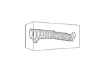
- the display unit 34 displays the three-dimensional image generated by the control unit 31, as shown in FIG. 4 as an example.
- the user can see the captured image displayed on the display unit 34 to understand the state of the captured location. It is preferable that the display unit 34 displays the updated latest captured image every time the captured image is updated by the control unit 31. This allows the user to check the latest captured image in real time.
- the input unit 35 receives an operation input from a user, for example.
- the input unit 35 includes, for example, operation buttons (operation keys).
- the input unit 35 may be configured by a touch screen, and an input area for receiving an operation input from the user may be displayed on a part of the display device to receive a touch operation input by the user.
- the ultrasonic wave transmission/reception unit 12 transmits the ultrasonic wave 512 times during one rotation, for example.
- the ultrasonic transmission/reception unit 12 receives the reflected wave 512 times during one rotation.
- the ultrasonic transmission/reception unit 12 transmits the received 512 signals to the information processing device 30 via the MDU 20.
- the information processing device 30 receives this signal, and the control unit 31 performs predetermined arithmetic processing to obtain 512 line data extending in the radial direction from the rotation center of the ultrasonic transmission/reception unit 12.
- This line data is dense at the center of rotation and becomes coarser as it moves away from the center of rotation.
- the control unit 31 performs a process of generating pixels between lines by interpolating between the lines in the line data.
- a blood vessel tomographic image (ultrasonic tomographic image) in a direction orthogonal to the axial direction of the blood vessel can be generated.
- the control unit 31 generates such a blood vessel tomographic image for the displacement length of the reciprocating motion.
- a three-dimensional image is generated by connecting the generated plurality of blood vessel tomographic images.
- the MDU 20 that functions as a drive unit includes the reciprocating drive unit 21 that continuously reciprocates the imaging core 11 along the longitudinal direction of the catheter 10.
- the collection of information on a three-dimensional structure in a predetermined range is continuously and continuously executed.
- the information processing device 30 receives the signal as the collection result, the information processing device 30 generates a captured image. Since the information processing apparatus 30 can continue to generate the latest captured image using the information that is continuously collected, the captured image of the patient can be continuously updated during the procedure by the doctor or the like.
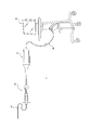
- FIG. 5 is a schematic diagram showing an example of the configuration of the image generation system 2 according to the second embodiment.
- FIG. 6 is a functional block diagram showing an example of a schematic configuration of the image generation system 2 of FIG.
- the MDU 20 functions as a drive unit
- the drive unit is configured as a device independent of the MDU
- the image generation system 2 according to the second embodiment will be described focusing on the differences from the image generation system 1 according to the first embodiment.
- the same members as those in the first embodiment are designated by the same reference numerals.
- the image generation system 2 includes a catheter 10, a drive unit 50, an MDU 60, and an information processing device 30.
- the functions and configurations of the catheter 10 and the information processing device 30 are the same as those in the first embodiment, and detailed description thereof will be omitted here.
- the image generation system 2 is used with the catheter 10 and the drive unit 50 connected, the drive unit 50 and the MDU 60 connected, and the MDU 60 and the information processing device 30 connected.
- the catheter 10 and the drive unit 50, and the drive unit 50 and the MDU 60 are mechanically and electrically connected to each other.
- the MDU 60 and the information processing device 30 are connected by wire or wirelessly so that they can communicate with each other.
- the MDU 60 and the information processing device 30 are connected by the cable 40, for example, as in the first embodiment.
- the drive unit 50 controls the reciprocating motion of the imaging core 11 in the state of being connected to the catheter 10.
- the drive unit 50 includes a reciprocating drive unit 21 for reciprocating the imaging core 11.
- the reciprocating drive unit 21 may include, for example, a piston crank mechanism.
- the function and configuration of the reciprocating drive unit 21 may be the same as in the first embodiment, and thus detailed description thereof is omitted here.
- the drive unit 50 further includes a first connecting portion 27 connected to the connecting portion 15 of the catheter 10.
- the 1st connection part 27 may be comprised by the connector, for example.
- the drive unit 50 also includes a second connecting portion 28 for connecting to the MDU 60.
- the drive unit 50 and the MDU 60 are connected by, for example, a cable.
- the second connecting portion 28 may be configured by a connector that can connect a cable.
- the cable used here can transmit the rotational movement of the MDU 60 and can also transmit and receive electric signals to and from the MDU 60.
- the MDU 60 controls the operation of the rotational movement and the pullback operation of the imaging core 11 in a state of being connected to the drive unit 50 connected to the catheter 10 and also functions as a relay device between the catheter 10 and the information processing device 30.
- the MDU 60 can be a known MDU.
- the MDU 60 includes a rotation driving unit 22, an electric signal transmitting/receiving unit 23, a communication unit 24, a connecting unit 25, and a linear driving unit 26.
- the functions and configurations of the rotation driving unit 22, the electric signal transmitting/receiving unit 23, the communication unit 24, the connecting unit 25, and the linear driving unit 26 may be the same as those in the first embodiment, and thus detailed description thereof will be omitted here.
- the connecting portion 25 is connected to the drive unit 50 instead of the catheter 10, which differs from the first embodiment.
- the drive unit 50 controls the reciprocating motion of the imaging core 11, and the MDU 60 controls the rotational motion of the imaging core 11. Further, in the image generation system 2 according to the present embodiment, a signal as a collection result of information regarding a three-dimensional structure is transmitted to the information processing device 30 via the drive unit 50 and the MDU 60. In the information processing device 30, the captured image is generated and updated by the same processing as that of the first embodiment. In this way, the image generation system 2 according to the present embodiment can also continuously update the imaged image of the patient during a procedure by a doctor or the like.
Landscapes
- Life Sciences & Earth Sciences (AREA)
- Health & Medical Sciences (AREA)
- Biomedical Technology (AREA)
- Biophysics (AREA)
- Nuclear Medicine, Radiotherapy & Molecular Imaging (AREA)
- Pathology (AREA)
- Radiology & Medical Imaging (AREA)
- Engineering & Computer Science (AREA)
- Physics & Mathematics (AREA)
- Heart & Thoracic Surgery (AREA)
- Medical Informatics (AREA)
- Molecular Biology (AREA)
- Surgery (AREA)
- Animal Behavior & Ethology (AREA)
- General Health & Medical Sciences (AREA)
- Public Health (AREA)
- Veterinary Medicine (AREA)
- Ultra Sonic Daignosis Equipment (AREA)
Abstract
駆動ユニットは、カテーテルに収容され先端に超音波送受信部を備えるイメージングコアを接続可能な接続部と、前記接続部に前記イメージングコアが接続された状態において、前記イメージングコアを、前記カテーテルの長手方向に沿って連続的に往復運動させる往復駆動部と、を備える。
Description
本発明は、駆動ユニット及び画像生成システムに関する。
従来、血管内腔を診断する装置として、血管内超音波診断装置(IVUS:IntraVascular Ultra Sound)や光干渉断層診断(OFDI:Optical Frequency Domain Imaging)画像診断装置等が知られている(例えば特許文献1参照)。
IVUSは、例えば慢性完全閉塞(CTO:Chronic Total Occlusion)病変に対して経皮的冠動脈形成術(PCI:percutaneous coronary intervention)を行うに際して用いることができる。医師は、血管の閉塞箇所にワイヤを通すために、IVUSで生成した画像を用いて手技を行う。具体的には、例えば医師は、血管内膜(intimal)の位置と、操作するワイヤの向き及び位置とを、IVUSで生成した2次元画像を見て特定し、特定した位置関係に基づいて、3次元的な位置関係を頭の中でイメージする。実際に手技を行う際には、医師は、血管造影(Angio)画像を見ながら、IVUSで生成した画像に基づいてイメージした3次元的な位置関係がAngio画像上において相当する位置を想像して、ワイヤの操作を行う。
しかしながら、このように手技を行う場合、血管内膜及びワイヤの3次元的な位置関係を想像しながら手技を行うため、医師にとっては難易度が高く、手技の時間がかかりやすい。また、手技の成否が、医師の技量によるところも大きくなりやすい。
一方、OFDIは、例えば血管の分岐部病変に対してステントを留置する手技を行うに際して用いることができる。具体的には、例えば医師は、患者の血管の分岐箇所において所望の位置にワイヤを通すために、OFDIにより生成された3次元画像を確認しながら、手技を行う。
しかしながら、OFDIは、光学的性質を利用して撮像を行うものであるため、撮像を行う場合には、血管中の血液を除去する必要がある。そのため、撮像に際しては、血管に造影剤を流して撮像を行い、その後、撮像された画像に基づいて生成された3次元画像を医師が確認して、ワイヤ操作を行う。OFDIによる撮像と、医師によるワイヤ操作とは、ワイヤが所望の位置に通るまで、順に繰り返される。このように、OFDIにより生成された3次元画像を確認しながら手技を行う場合、撮像とワイヤ操作とを順に行うため、手技を完了するまでに時間がかかる。また、医師が確認する3次元画像が、必ずしも現在のワイヤの位置と一致するとは限らない。つまり、リアルタイム性が損なわれやすい。
本発明の目的は、医師等による手技に際して、撮像した患者の画像を継続的に更新可能な駆動ユニット及び画像生成システムを提供することである。
本発明の第1の態様としての駆動ユニットは、カテーテルに収容され先端に超音波送受信部を備えるイメージングコアを接続可能な接続部と、前記接続部に前記イメージングコアが接続された状態において、前記イメージングコアを、前記カテーテルの長手方向に沿って連続的に往復運動させる往復駆動部と、を備える。
本発明の一実施形態としての駆動ユニットにおいて、前記往復駆動部は、ピストンクランク機構により、前記イメージングコアを往復運動させる。
本発明の一実施形態としての駆動ユニットにおいて、前記往復駆動部は、クランク軸を中心とした回転運動を行うクランクアームと、一端側において前記クランクアームに接続され、他端側においてシリンダの延在方向に沿って変位可能なピストンに接続されているコネクティングロッドとを備え、前記コネクティングロッドは、前記一端側における前記クランクアームへの接続位置が可変に構成されている。
本発明の一実施形態としての駆動ユニットにおいて、前記往復駆動部は、前記イメージングコアを、15フィート毎秒以上の速度で往復運動させる。
本発明の一実施形態としての駆動ユニットは、前記接続部に前記イメージングコアが接続された状態において、前記イメージングコアが備える駆動シャフトを、前記イメージングコアの長手方向を軸として回転させる回転駆動部をさらに備える。
本発明の一実施形態としての駆動ユニットは、当該駆動ユニットが前記超音波送受信部と電気的に接続された状態で、前記超音波送受信部と電気信号の送受信を行う電気信号送受信部をさらに備える。
本発明の一実施形態としての駆動ユニットは、前記接続部に前記イメージングコアが接続された状態において、前記イメージングコアを前記カテーテルの長手方向に沿って先端側から後端側に変位させる直線駆動部をさらに備える。
本発明の第2の態様としての画像生成システムは、上述の駆動ユニットと、前記超音波送受信部で受信された超音波信号に基づいて、撮像画像を生成する情報処理装置と、を備える。
本発明の一実施形態としての画像生成システムにおいて、前記情報処理装置は、前記イメージングコアの往復運動に応じて前記超音波送受信部で受信された新たな超音波信号に基づいて、前記生成した撮像画像を更新する。
本発明の一実施形態としての画像生成システムにおいて、前記情報処理装置は3次元の撮像画像を生成する。
本発明によると、医師等による手技に際して、撮像した患者の画像を継続的に更新可能な駆動ユニット及び画像生成システムを提供できる。
以下、本発明の実施形態について、図面を参照して説明する。各図において同一の構成要素には、同一の符号を付している。以下に述べる実施形態は、本発明の好適な具体例であるため、技術的に好ましい種々の限定が付されているが、本発明の範囲は、以下の説明において特に本発明を限定する旨の記載がない限り、これらの態様に限られるものではない。
(第1実施形態)
図1は、第1実施形態に係る画像生成システム1の構成の一例を示す概略図である。図2は、図1の画像生成システム1の概略構成の一例を示す機能ブロック図である。画像生成システム1は、カテーテル10と、モータドライブユニット(以下、単に「MDU」ともいう)20と、情報処理装置30とを備える。本実施形態におけるMDU20は、本発明における駆動ユニットとして機能する。すなわち、MDU20は、駆動ユニットが具体化されたものの一例を示すものである。
図1は、第1実施形態に係る画像生成システム1の構成の一例を示す概略図である。図2は、図1の画像生成システム1の概略構成の一例を示す機能ブロック図である。画像生成システム1は、カテーテル10と、モータドライブユニット(以下、単に「MDU」ともいう)20と、情報処理装置30とを備える。本実施形態におけるMDU20は、本発明における駆動ユニットとして機能する。すなわち、MDU20は、駆動ユニットが具体化されたものの一例を示すものである。
画像生成システム1は、カテーテル10がMDU20に接続された状態で使用される。また、画像生成システム1は、MDU20と情報処理装置30とが有線又は無線により通信可能に接続された状態で使用される。MDU20と情報処理装置30とは、例えば図1に示すように、信号線等を収容したケーブル40により接続されている。MDU20と情報処理装置30とは、例えばLAN(Local Area Network)等のネットワークにより、無線接続されていてもよい。
画像生成システム1は、例えば医師が手技を行う際に、患者の体内の特定の箇所を撮像するために用いられる。特定の箇所は、例えば診断対象の箇所であり、具体的には、例えば血管内の箇所であってよい。
具体的には、カテーテル10が患者の体内の特定の箇所に挿入され、カテーテル10に収容されたイメージングコア11により、当該特定の箇所の3次元構造に関する情報が収集される。そして、イメージングコア11から、収集された情報の信号がMDU20に送信される。MDU20は、イメージングコア11から受信した信号を、情報処理装置30に送信する。情報処理装置30は、受信した信号に基づいて特定の箇所の3次元画像を生成し、ディスプレイ等の表示部34に表示する。医師は、表示部34に表示された3次元画像を見ながら、手技を行うことができる。
カテーテル10は、患者の体内に直接挿入される。カテーテル10は、長手方向に移動自在である。カテーテル10は、内部にイメージングコア11を収容する。イメージングコア11は、長手方向を軸として回転自在に、カテーテル10に収容されている。イメージングコア11の先端には、超音波送受信部12が設けられている。イメージングコア11は、超音波送受信部12から、例えば患者の血管組織に向けて超音波を出射し、出射した超音波の反射波を受光することにより、患者の体内の特定の箇所の3次元構造に関する情報を、超音波信号として収集する。
超音波送受信部12は、ハウジング13に収納されている。ハウジング13には、カテーテル10がMDU20に接続された状態において、MDU20からのイメージングコア11の長手方向を軸とした回転運動と、後述する往復運動とを伝達するための駆動シャフト14が接続されている。すなわち、イメージングコア11は、超音波送受信部12が設けられたハウジング13と駆動シャフト14とにより構成される。
また、カテーテル10は、後端に、カテーテル10をMDU20に接続するための接続部15を備える。カテーテル10の接続部15が、MDU20の接続部25に接続されることにより、カテーテル10がMDU20に接続される。
MDU20は、カテーテル10のイメージングコア11の動作を制御するとともに、カテーテル10と情報処理装置30との中継装置として機能する。MDU20は、カテーテル10の接続部15と接続される接続部25を備える。接続部25は、例えば接続コネクタにより構成されていてよい。ただし、接続部25は、接続コネクタ以外の他の接続可能な機構又は部品により構成されていてよい。
カテーテル10の接続部15とMDU20の接続部25とが接続されることにより、カテーテル10とMDU20とは、機械的かつ電気的に互いに接続される。カテーテル10とMDU20とが機械的に接続されることにより、後述するような、MDU20の制御によるイメージングコア11の駆動が可能となる。また、カテーテル10とMDU20とが電気的に接続されることにより、カテーテル10とMDU20とにおける信号の送受信が可能となる。
MDU20は、カテーテル10と接続された状態において、イメージングコア11を動作させる駆動ユニットとして機能する。MDU20は、往復駆動部21を備える。往復駆動部21は、MDU20がカテーテル10に接続された状態において、カテーテル10の長手方向に沿って、イメージングコア11を連続的に往復運動させる。往復駆動部21は、例えばピストンクランク機構を含んで構成されていてよい。
図3は、図2の往復駆動部21の具体的な構成の一例を示す模式図であり、ピストンクランク機構により構成される場合の往復駆動部21の具体例を示す模式図である。往復駆動部21は、例えば図3に示すようにピストンクランク機構により構成される場合、シリンダ211と、ピストン212と、コネクティングロッド213と、クランクシャフト214とを備える。クランクシャフト214は、クランクアーム215を備える。クランクアーム215は、一端がクランク軸側に位置し、他端がクランクシャフト214の径方向外側に位置する。クランクアーム215は、クランク軸を中心とした回転運動を行う。コネクティングロッド213の一端は、クランクアーム215の上記他端に接続されている。また、コネクティングロッド213の他端は、ピストン212に接続されている。ピストン212は、シリンダ211の延在方向に沿って変位可能となるように、シリンダ211の内部に配置されている。クランクシャフト214が回転すると、クランクアーム215及びコネクティングロッド213を介して、クランクシャフト214の回転運動がシリンダ211の延在方向の直線運動に変換される。このようにして、クランクシャフト214が回転することにより、ピストン212はシリンダ211の延在方向に往復運動を行う。
カテーテル10とMDU20とが接続された状態において、ピストン212がイメージングコア11の駆動シャフト14に機械的に接続されることにより、ピストン212の直線運動(つまり往復運動)がイメージングコア11に伝達される。これにより、イメージングコア11を往復運動させることができる。イメージングコア11の往復運動に伴い、駆動シャフト14に接続されたハウジング13内の超音波送受信部12が、カテーテル10の長手方向に沿った往復運動を行う。
往復駆動部21によるイメージングコア11の往復運動の速度が速いほど、超音波送受信部12はよりリアルタイムな特定の箇所の走査(3次元構造に関する情報の収集)を行うことができる。そのため、往復駆動部21によるイメージングコア11の往復運動の速度は、速い方が好ましい。往復駆動部21は、例えば、イメージングコア11を、15フィート毎秒以上の速度で往復運動させることが好ましい。
イメージングコア11の往復運動により、超音波送受信部12は、特定の箇所について、所定の範囲にわたる走査を行うことができる。具体的には、超音波送受信部12は、往復運動の変位長にわたる走査を行うことができる。往復運動の変位長は、クランクアーム215の長さに応じて定まる。コネクティングロッド213のクランクアーム215に接続される一端側について、クランクアーム215に接続される位置が可変となるように構成してもよい。つまり、コネクティングロッド213は、一端側におけるクランクアーム215への接続位置が可変に構成されていてよい。これにより、例えば画像生成システム1のユーザ等に、往復運動の変位長を変更させることができる。変位長は、例えば1~20mmの範囲で変更可能に構成されてよい。ただし、変位長の変更可能な範囲は、これに限られず、画像生成ユニット1において所望される範囲に適宜設定されてよい。
なお、往復駆動部21は、必ずしもピストンクランク機構を含んでいなくてもよい。往復駆動部21は、イメージングコア11を往復運動させることが可能な任意の機構により構成されていてよい。
MDU20は、さらに回転駆動部22と、電気信号送受信部23と、通信部24と、直線駆動部26とを備える。
回転駆動部22は、カテーテル10がMDU20に接続された状態において、イメージングコア11を回転させる。具体的には、回転駆動部22は、イメージングコア11の駆動シャフトを、イメージングコア11の長手方向を軸として回転運動させる。回転駆動部22は、例えば内蔵するモータを駆動することにより、イメージングコア11を回転させることができる。イメージングコア11の回転運動により、超音波送受信部12が長手方向を軸とした回転運動を行う。これにより、超音波送受信部12は、患者の体内の特定の箇所について、イメージングコア11の周方向に沿った走査を行うことができる。
電気信号送受信部23は、カテーテル10がMDU20に接続された状態において、カテーテル10の超音波送受信部12と電気信号の送受信を行う。例えば、電気信号送受信部23は、超音波送受信部12に対して、3次元構造に関する情報の収集を開始及び停止させる電気信号を送信する。電気信号送受信部23は、例えばMDU20に設けられている各種ボタンもしくはスイッチに対する入力操作に基づいて、又は、情報処理装置30から受信した信号に基づいて、各種電気信号を送信することができる。また、例えば、電気信号送受信部23は、超音波送受信部12から、3次元構造に関する情報の収集結果としての超音波信号に対応する電気信号を受信する。なお、本実施形態では、MDU20が電気信号送受信部23を備える場合について説明するが、電気信号送受信部23は、必ずしもMDU20が備えていなくてもよく、例えば情報処理装置30が備えていてもよい。
直線駆動部26は、イメージングコア11のプルバック動作を実行する。直線駆動部26は、例えばモータを備え、モータを駆動させることにより、イメージングコア11をカテーテル10の長手方向に沿って先端側から後端側に変位させる。例えば、直線駆動部26は、0.5mm/s~10mm/sの速度でイメージングコア11を変位させることができる。直線駆動部26は、イメージングコア11を、往復駆動部21による変位長よりも長い距離変位させることができる。直線駆動部26は、イメージングコア11を、例えば150mm変位させることができる。ただし、直線駆動部26を変位させる距離はこれにかぎられず、画像生成ユニット1において所望される範囲に適宜設定されてよい。
本実施形態において、イメージングコア11は、第1の動作と第2の動作とを実行可能である。イメージングコア11は、例えばMDU20に設けられている各種ボタンもしくはスイッチに対する入力操作に基づいて、又は、情報処理装置30から受信した信号に基づいて、第1の動作又は第2の動作のいずれかを実行する。
第1の動作は、往復駆動部21と回転駆動部22とにより実行される動作である。第1の動作は、イメージングコア11が、往復駆動部21による駆動により往復運動を行いながら、回転駆動部22による駆動により回転運動を行う動作である。イメージングコア11が第1の動作を行っている間、超音波送受信部12は、超音波を出射し、超音波の反射波を受光することにより、3次元構造に関する情報の収集を行う。往復運動により、超音波送受信部12は、所定の範囲の3次元構造に関する情報の収集を連続的に実行する。超音波送受信部12は、3次元構造に関する情報の収集結果としての信号を、都度、MDU20に送信する。
第2の動作は、直線駆動部26と回転駆動部22とにより実行される動作である。第2の動作は、イメージングコア11が、直線駆動部26による駆動により先端側から後端側への変位を行いながら、回転駆動部22による駆動により回転運動を行う動作である。イメージングコア11が第2の動作を行っている間、超音波送受信部12は、超音波を出射し、超音波の反射波を受光することにより、3次元構造に関する情報の収集を行う。第2の動作では、イメージングコア11が直線駆動部26により変位されるため、第1の動作と比較して、より広い範囲の画像を取得することができる。
MDU20は、往復駆動部21、回転駆動部22及び直線駆動部26を備えることにより、ユーザが確認したい画像に応じて、第1の動作又は第2の動作を選択的に実行させることができる。なお、以下では、特に第1の動作に関する処理を中心に説明する。
通信部24は、情報処理装置30と有線通信若しくは無線通信、又は有線通信及び無線通信の組合せの通信を行うことにより、各種情報の送受信を行う。本実施形態では、通信部24は、ケーブル40を用いた有線通信により、情報の送受信を行う。通信部24は、例えば、超音波送受信部12から受信した3次元構造に関する情報の収集結果を、情報処理装置30に送信する。通信部24は、超音波送受信部12から継続的に送信される3次元構造に関する情報の収集結果を、都度、情報処理装置30に送信してよい。通信部24は、超音波送受信部12から継続的に送信される3次元構造に関する情報の収集結果を、一定の時間間隔で、情報処理装置30に送信してもよい。例えば、通信部24は、超音波送受信部12から継続的に送信される3次元構造に関する情報の収集結果を、1往復分の往復運動が行われる時間間隔で、情報処理装置30に送信してもよい。この場合、通信部24は、1往復分の収集結果が蓄積されると、情報処理装置30に送信する。
また、MDU20には、上述した各種機能ブロックの他に、各種ボタン及びスイッチが設けられる。医師等のユーザは、これらのボタン及びスイッチを操作することで、MDU20に特定の動作を実行させることができる。
情報処理装置30は、例えばコンピュータ装置等により構成されている。情報処理装置30は、MDU20を介して受信した信号に基づき、超音波送受信部12により走査された患者の体内の特定の箇所の3次元画像(以下「撮像画像」ともいう)を生成し、表示する。情報処理装置30は、機能ブロックとして、例えば図2に一例として示すように、制御部31と、記憶部32と、通信部33と、表示部34と、入力部35とを備える。
制御部31は、情報処理装置30が備える各機能ブロックをはじめとして、情報処理装置30の全体を制御及び管理するプロセッサである。制御部31は、制御手順を規定したプログラムを実行するCPU(Central Processing Unit)等のプロセッサで構成される。プロセッサにより実行されるプログラムは、例えば記憶部32又は外部の記憶媒体等に格納される。
制御部31は、MDU20を介して受信した信号に基づき、撮像画像を生成する。具体的には、情報処理装置30は、MDU20を介して、通信部33から、超音波送受信部12により受信された超音波信号に対応する電気信号を受信し、当該電気信号に基づいて、撮像画像を生成する。制御部31は、3次元の撮像画像を生成してよい。3次元の撮像画像を生成することにより、撮像画像が表示部34に表示されると、ユーザは、撮像された特定の部位を、容易に3次元的に把握しやすくなる。
制御部31は、MDU20から継続的に送信される信号に基づき、継続的に撮像画像を生成してよい。制御部31は、生成された最新の撮像画像により、過去の撮像画像を更新してよい。これにより、制御部31は、最新の撮像画像を生成し続けることができる。最新の撮像画像が表示部34に表示されることにより、ユーザは、リアルタイムの撮像画像を確認することができる。そのため、ユーザは、リアルタイムの撮像画像を見ながら、手技を行うことができる。
記憶部32は、多様なメモリデバイスを有し、用途に応じてそれぞれ各種情報、例えば、制御部31の動作に必要なデータなどを記憶する。例えば、記憶部32は、半導体メモリ又は磁気メモリ等で構成されることができる。記憶部32は、各種情報や情報処理装置30を動作させるためのプログラム等を記憶する。また、記憶部32は、ワークメモリとして機能するRAM(Random Access Memory)等のデバイスも有する。
記憶部32は、例えばMDU20から受信した信号のデータを記憶してよい。記憶部32は、例えば生成した撮像画像のデータを記憶してよい。この場合、記憶部32は、生成した撮像画像を、都度記憶することにより、撮像画像の時系列的な変化を履歴として記憶してよい。
通信部33は、MDU20と有線通信若しくは無線通信、又は有線通信及び無線通信の組合せの通信を行うことにより、各種情報の送受信を行う。本実施形態では、通信部33は、ケーブル40を用いた有線通信により、情報の送受信を行う。通信部33は、例えば、3次元構造に関する情報の収集結果を、MDU20から受信する。
表示部34は、LED(Light Emitting Diode)ディスプレイ、液晶ディスプレイ(LCD:Liquid Crystal Display)又は有機ELディスプレイ(OELD:Organic Electroluminescence Display)等の周知のディスプレイにより構成される表示デバイスである。
表示部34は、制御部31により生成された撮像画像が表示される。例えば、表示部34には、図4に一例として示すように、制御部31により生成された3次元画像が表示される。ユーザは、表示部34に表示された撮像画像を見て、撮像された箇所の状態を把握することができる。表示部34は、制御部31により撮像画像が更新されるたび、更新された最新の撮像画像を表示することが好ましい。これにより、ユーザは、最新の撮像画像をリアルタイムで確認することができる。
入力部35は、例えばユーザからの操作入力を受け付けるものである。入力部35は、例えば、操作ボタン(操作キー)により構成される。入力部35をタッチスクリーンにより構成し、表示デバイスの一部にユーザからの操作入力を受け付ける入力領域を表示して、ユーザによるタッチ操作入力を受け付けてもよい。
ここで、カテーテル10の超音波送受信部12による3次元構造に関する情報の収集と、情報処理装置30の制御部31による3次元画像の生成について、一例を挙げてさらに具体的に説明する。超音波送受信部12は、例えば1回転の間に512回の超音波の送信を行う。この場合、超音波送受信部12は、1回転の間に512回の反射波の受信を行う。超音波送受信部12は、受信した512回分の信号を、MDU20を介して情報処理装置30に送信する。情報処理装置30は、この信号を受信し、制御部31において、所定の演算処理を行うことで、超音波送受信部12の回転中心から放射線方向に延びる512本のラインデータを得る。このラインデータは回転の中心位置では密で、回転中心から離れるに従い互いに粗となる。制御部31は、ラインデータにおける各ライン間を補間することにより、ライン間の画素を生成する処理を行う。この結果、血管の軸方向に直交する方向の血管断層画像(超音波断層画像)が生成できる。制御部31は、このような血管断層画像を、往復運動の変位長分、生成する。そして、生成した複数の血管断層画像をつなぎ合わせることにより、3次元画像を生成する。
このように、本実施形態に係る画像生成システム1によれば、駆動ユニットとして機能するMDU20が、イメージングコア11をカテーテル10の長手方向に沿って連続的に往復運動させる往復駆動部21を備えるため、所定の範囲の3次元構造に関する情報の収集が連続的に継続して実行される。情報処理装置30は、収集結果としての信号を受信すると、撮像画像を生成する。情報処理装置30は、連続的に収集される情報を用いて最新の撮像画像を生成し続けることができるため、医師等による手技に際して、撮像した患者の画像を継続的に更新可能となる。
(第2実施形態)
図5は、第2実施形態に係る画像生成システム2の構成の一例を示す概略図である。図6は、図5の画像生成システム2の概略構成の一例を示す機能ブロック図である。第1実施形態では、MDU20が駆動ユニットとして機能する場合の例について説明した。第2実施形態では、駆動ユニットが、MDUとは独立した装置として構成される場合の例について説明する。ここでは、第2実施形態に係る画像生成システム2について、第1実施形態に係る画像生成システム1と異なる点を中心に説明する。なお、本実施形態について、第1実施形態と同じ部材については、同一の参照符号を付す。
図5は、第2実施形態に係る画像生成システム2の構成の一例を示す概略図である。図6は、図5の画像生成システム2の概略構成の一例を示す機能ブロック図である。第1実施形態では、MDU20が駆動ユニットとして機能する場合の例について説明した。第2実施形態では、駆動ユニットが、MDUとは独立した装置として構成される場合の例について説明する。ここでは、第2実施形態に係る画像生成システム2について、第1実施形態に係る画像生成システム1と異なる点を中心に説明する。なお、本実施形態について、第1実施形態と同じ部材については、同一の参照符号を付す。
図5に示すように、本実施形態に係る画像生成システム2は、カテーテル10と、駆動ユニット50と、MDU60と、情報処理装置30とを備える。カテーテル10及び情報処理装置30の機能及び構成は、第1実施形態と同様であるため、ここでは詳細な説明を省略する。
画像生成システム2は、カテーテル10と駆動ユニット50とが接続され、駆動ユニット50とMDU60とが接続され、MDU60と情報処理装置30とが接続された状態で使用される。カテーテル10と駆動ユニット50、及び、駆動ユニット50とMDU60は、それぞれ機械的かつ電気的に互いに接続される。MDU60と情報処理装置30とは、有線又は無線により通信可能に接続される。MDU60と情報処理装置30とは、例えば第1実施形態と同様に、ケーブル40により接続されている。
駆動ユニット50は、カテーテル10と接続された状態において、イメージングコア11の往復運動の動作を制御する。駆動ユニット50は、イメージングコア11を往復運動させるための往復駆動部21を備える。往復駆動部21は、例えばピストンクランク機構を含んで構成されていてよい。往復駆動部21の機能及び構成は、第1実施形態と同様であってよいため、ここでは詳細な説明を省略する。
駆動ユニット50は、さらに、カテーテル10の接続部15と接続される第1接続部27を備える。第1接続部27は、例えば接続コネクタにより構成されていてよい。
また、駆動ユニット50は、MDU60と接続するための第2接続部28を備える。駆動ユニット50とMDU60とは、例えばケーブルにより接続される。第2接続部28は、ケーブルを接続可能なコネクタにより構成されていてよい。なお、ここで使用されるケーブルは、MDU60による回転運動を伝達可能であり、かつ、MDU60と電気信号の送受信が可能である。
MDU60は、カテーテル10と接続された駆動ユニット50と接続された状態において、イメージングコア11の回転運動の動作及びプルバック動作を制御するとともに、カテーテル10と情報処理装置30との中継装置として機能する。本実施形態において、MDU60は、公知のMDUとすることができる。
MDU60は、回転駆動部22と、電気信号送受信部23と、通信部24と、接続部25と、直線駆動部26とを備える。回転駆動部22、電気信号送受信部23、通信部24、接続部25及び直線駆動部26の機能及び構成は、第1実施形態と同様であってよいため、ここでは詳細な説明を省略する。なお、本実施形態では、接続部25は、カテーテル10ではなく、駆動ユニット50に接続される点で、第1実施形態と異なる。
本実施形態に係る画像生成システム2では、駆動ユニット50によりイメージングコア11の往復運動が制御され、MDU60によりイメージングコア11の回転運動が制御される。また、本実施形態に係る画像生成システム2では、3次元構造に関する情報の収集結果としての信号が、駆動ユニット50及びMDU60を介して情報処理装置30に送信される。情報処理装置30においては、第1実施形態と同様の処理により、撮像画像が生成され、更新される。このようにして、本実施形態に係る画像生成システム2によっても、医師等による手技に際して、撮像した患者の画像を継続的に更新可能となる。
本発明は、上述した各実施形態で特定された構成に限定されるものではなく、特許請求の範囲に記載した内容を逸脱しない範囲内で種々の変形が可能である。
1,2 画像生成システム
10 カテーテル
11 イメージングコア
12 超音波送受信部
13 ハウジング
14 駆動シャフト
15,25 接続部
20,60 モータドライブユニット(MDU)
21 往復駆動部
22 回転駆動部
23 電気信号送受信部
24,33 通信部
26 直線駆動部
27 第1接続部
28 第2接続部
30 情報処理装置
31 制御部
32 記憶部
34 表示部
35 入力部
40 ケーブル
50 駆動ユニット
211 シリンダ
212 ピストン
213 コネクティングロッド
214 クランクシャフト
215 クランクアーム
10 カテーテル
11 イメージングコア
12 超音波送受信部
13 ハウジング
14 駆動シャフト
15,25 接続部
20,60 モータドライブユニット(MDU)
21 往復駆動部
22 回転駆動部
23 電気信号送受信部
24,33 通信部
26 直線駆動部
27 第1接続部
28 第2接続部
30 情報処理装置
31 制御部
32 記憶部
34 表示部
35 入力部
40 ケーブル
50 駆動ユニット
211 シリンダ
212 ピストン
213 コネクティングロッド
214 クランクシャフト
215 クランクアーム
Claims (10)
- カテーテルに収容され先端に超音波送受信部を備えるイメージングコアを接続可能な接続部と、
前記接続部に前記イメージングコアが接続された状態において、前記イメージングコアを、前記カテーテルの長手方向に沿って連続的に往復運動させる往復駆動部と、
を備える、駆動ユニット。 - 前記往復駆動部は、ピストンクランク機構により、前記イメージングコアを往復運動させる、請求項1に記載の駆動ユニット。
- 前記往復駆動部は、
クランク軸を中心とした回転運動を行うクランクアームと、
一端側において前記クランクアームに接続され、他端側においてシリンダの延在方向に沿って変位可能なピストンに接続されているコネクティングロッドと
を備え、
前記コネクティングロッドは、前記一端側における前記クランクアームへの接続位置が可変に構成されている、
請求項2に記載の駆動ユニット。 - 前記往復駆動部は、前記イメージングコアを、15フィート毎秒以上の速度で往復運動させる、請求項1-3のいずれか一項に記載の駆動ユニット。
- 前記接続部に前記イメージングコアが接続された状態において、前記イメージングコアが備える駆動シャフトを、前記イメージングコアの長手方向を軸として回転させる回転駆動部
をさらに備える、請求項1-4のいずれか一項に記載の駆動ユニット。 - 当該駆動ユニットが前記超音波送受信部と電気的に接続された状態で、前記超音波送受信部と電気信号の送受信を行う電気信号送受信部
をさらに備える、請求項1-5のいずれか一項に記載の駆動ユニット。 - 前記接続部に前記イメージングコアが接続された状態において、前記イメージングコアを前記カテーテルの長手方向に沿って先端側から後端側に変位させる直線駆動部
をさらに備える、請求項1-6のいずれか一項に記載の駆動ユニット。 - 請求項1-7のいずれか一項に記載の駆動ユニットと、
前記超音波送受信部で受信された超音波信号に基づいて、撮像画像を生成する情報処理装置と、
を備える、画像生成システム。 - 前記情報処理装置は、前記イメージングコアの往復運動に応じて前記超音波送受信部で受信された新たな超音波信号に基づいて、前記生成した撮像画像を更新する、請求項8に記載の画像生成システム。
- 前記情報処理装置は3次元の撮像画像を生成する、請求項8又は9に記載の画像生成システム。
Priority Applications (1)
| Application Number | Priority Date | Filing Date | Title |
|---|---|---|---|
| JP2020566512A JP7433248B2 (ja) | 2019-01-17 | 2020-01-17 | 駆動ユニット及び画像生成システム |
Applications Claiming Priority (2)
| Application Number | Priority Date | Filing Date | Title |
|---|---|---|---|
| JP2019-006425 | 2019-01-17 | ||
| JP2019006425 | 2019-01-17 |
Publications (1)
| Publication Number | Publication Date |
|---|---|
| WO2020149415A1 true WO2020149415A1 (ja) | 2020-07-23 |
Family
ID=71613262
Family Applications (1)
| Application Number | Title | Priority Date | Filing Date |
|---|---|---|---|
| PCT/JP2020/001600 Ceased WO2020149415A1 (ja) | 2019-01-17 | 2020-01-17 | 駆動ユニット及び画像生成システム |
Country Status (2)
| Country | Link |
|---|---|
| JP (1) | JP7433248B2 (ja) |
| WO (1) | WO2020149415A1 (ja) |
Citations (5)
| Publication number | Priority date | Publication date | Assignee | Title |
|---|---|---|---|---|
| JPS63302836A (ja) * | 1987-06-04 | 1988-12-09 | Olympus Optical Co Ltd | 内視鏡用超音波診断装置 |
| EP0363516A1 (en) * | 1988-10-14 | 1990-04-18 | Becton, Dickinson and Company | Thermoelectric chiller and automatic syringue |
| JPH03258252A (ja) * | 1990-03-06 | 1991-11-18 | Olympus Optical Co Ltd | 超音波観測装置 |
| JP2002513607A (ja) * | 1998-05-07 | 2002-05-14 | シメッド ライフ システムズ インコーポレイテッド | 超音波画像システムのための、組み合わされたモータドライブと長手方向位置自動並進器 |
| JP2003144376A (ja) * | 2001-11-19 | 2003-05-20 | Pentax Corp | 内視鏡の引張操作機構 |
Family Cites Families (1)
| Publication number | Priority date | Publication date | Assignee | Title |
|---|---|---|---|---|
| JP4119497B2 (ja) * | 1997-03-24 | 2008-07-16 | オリンパス株式会社 | 超音波画像診断装置 |
-
2020
- 2020-01-17 WO PCT/JP2020/001600 patent/WO2020149415A1/ja not_active Ceased
- 2020-01-17 JP JP2020566512A patent/JP7433248B2/ja active Active
Patent Citations (5)
| Publication number | Priority date | Publication date | Assignee | Title |
|---|---|---|---|---|
| JPS63302836A (ja) * | 1987-06-04 | 1988-12-09 | Olympus Optical Co Ltd | 内視鏡用超音波診断装置 |
| EP0363516A1 (en) * | 1988-10-14 | 1990-04-18 | Becton, Dickinson and Company | Thermoelectric chiller and automatic syringue |
| JPH03258252A (ja) * | 1990-03-06 | 1991-11-18 | Olympus Optical Co Ltd | 超音波観測装置 |
| JP2002513607A (ja) * | 1998-05-07 | 2002-05-14 | シメッド ライフ システムズ インコーポレイテッド | 超音波画像システムのための、組み合わされたモータドライブと長手方向位置自動並進器 |
| JP2003144376A (ja) * | 2001-11-19 | 2003-05-20 | Pentax Corp | 内視鏡の引張操作機構 |
Also Published As
| Publication number | Publication date |
|---|---|
| JP7433248B2 (ja) | 2024-02-19 |
| JPWO2020149415A1 (ja) | 2021-11-25 |
Similar Documents
| Publication | Publication Date | Title |
|---|---|---|
| JP6192846B2 (ja) | 血管内超音波撮像システムを使用して画像を選択し表示するためのシステム | |
| JP4578976B2 (ja) | 走査プローブ | |
| JP6117772B2 (ja) | プローブ及び画像診断装置 | |
| EP2113201B1 (en) | Moveable ultrasound element for use in medical diagnostic equipment | |
| JP6031089B2 (ja) | プローブ及び画像診断装置 | |
| JP6095770B2 (ja) | 画像診断装置及びその作動方法、プログラム及びコンピュータ可読記憶媒体 | |
| WO2008002442A2 (en) | Scanning probe with integrated electronics | |
| US10123780B2 (en) | Medical image diagnosis apparatus, image processing apparatus, and image processing method | |
| JP6563941B2 (ja) | 画像診断プローブ | |
| EP2941194B1 (en) | Reciprocating ultrasound device | |
| CN107928709B (zh) | 一种内窥成像系统及其控制方法 | |
| JP2002153472A (ja) | 画像診断装置 | |
| JP4119497B2 (ja) | 超音波画像診断装置 | |
| JP6437920B2 (ja) | 画像診断装置 | |
| US20140180120A1 (en) | Ultrasound Imaging Catheters with Reciprocating Phased Array Transducers | |
| KR102333542B1 (ko) | 초음파 프로브 및 그 제어 방법 | |
| CN101516271B (zh) | 超声波图像处理装置以及超声波诊断装置 | |
| WO2014049641A1 (ja) | 画像診断装置及び情報処理装置並びにそれらの制御方法 | |
| JP7433248B2 (ja) | 駆動ユニット及び画像生成システム | |
| JP7032157B2 (ja) | 医用画像診断装置及びx線照射制御装置 | |
| JPH0810263A (ja) | 超音波・内視鏡複合システム | |
| JP2000197631A (ja) | 超音波探触子及び超音波診断装置 | |
| JP2004209277A (ja) | 超音波画像診断装置 | |
| CN106606364B (zh) | 超声探头 | |
| JP2019063508A (ja) | 超音波診断装置、及び制御プログラム |
Legal Events
| Date | Code | Title | Description |
|---|---|---|---|
| 121 | Ep: the epo has been informed by wipo that ep was designated in this application |
Ref document number: 20741472 Country of ref document: EP Kind code of ref document: A1 |
|
| ENP | Entry into the national phase |
Ref document number: 2020566512 Country of ref document: JP Kind code of ref document: A |
|
| NENP | Non-entry into the national phase |
Ref country code: DE |
|
| 122 | Ep: pct application non-entry in european phase |
Ref document number: 20741472 Country of ref document: EP Kind code of ref document: A1 |