WO2020148971A1 - 試料供給装置、該試料供給装置を含む誘導結合プラズマ分析システム、及び試料供給方法 - Google Patents
試料供給装置、該試料供給装置を含む誘導結合プラズマ分析システム、及び試料供給方法 Download PDFInfo
- Publication number
- WO2020148971A1 WO2020148971A1 PCT/JP2019/043002 JP2019043002W WO2020148971A1 WO 2020148971 A1 WO2020148971 A1 WO 2020148971A1 JP 2019043002 W JP2019043002 W JP 2019043002W WO 2020148971 A1 WO2020148971 A1 WO 2020148971A1
- Authority
- WO
- WIPO (PCT)
- Prior art keywords
- sample
- plasma
- droplet
- sample supply
- torch
- Prior art date
- Legal status (The legal status is an assumption and is not a legal conclusion. Google has not performed a legal analysis and makes no representation as to the accuracy of the status listed.)
- Ceased
Links
Images


Classifications
-
- G—PHYSICS
- G01—MEASURING; TESTING
- G01N—INVESTIGATING OR ANALYSING MATERIALS BY DETERMINING THEIR CHEMICAL OR PHYSICAL PROPERTIES
- G01N21/00—Investigating or analysing materials by the use of optical means, i.e. using sub-millimetre waves, infrared, visible or ultraviolet light
- G01N21/62—Systems in which the material investigated is excited whereby it emits light or causes a change in wavelength of the incident light
- G01N21/71—Systems in which the material investigated is excited whereby it emits light or causes a change in wavelength of the incident light thermally excited
- G01N21/73—Systems in which the material investigated is excited whereby it emits light or causes a change in wavelength of the incident light thermally excited using plasma burners or torches
-
- H—ELECTRICITY
- H05—ELECTRIC TECHNIQUES NOT OTHERWISE PROVIDED FOR
- H05H—PLASMA TECHNIQUE; PRODUCTION OF ACCELERATED ELECTRICALLY-CHARGED PARTICLES OR OF NEUTRONS; PRODUCTION OR ACCELERATION OF NEUTRAL MOLECULAR OR ATOMIC BEAMS
- H05H1/00—Generating plasma; Handling plasma
- H05H1/24—Generating plasma
- H05H1/26—Plasma torches
Definitions
- the present invention relates to a sample supply device, an inductively coupled plasma analysis system including the sample supply device, and a sample supply method.
- An optical emission spectrometer or mass spectrometer that uses plasma such as inductively coupled plasma (ICP) as an atomization source or an ionization source is highly versatile in a wide range of fields such as material analysis, environmental analysis, and small amount analysis. It is known as a highly sensitive elemental analyzer.
- ICP inductively coupled plasma
- inductively coupled plasma analysis system In an inductively coupled plasma optical emission spectrometer or an inductively coupled plasma mass spectrometer (hereinafter collectively referred to as “inductively coupled plasma analysis system”), a liquid sample is supplied to a plasma source to generate plasma (excitation). ) And perform analysis based on the light emission from the plasma and the ionized sample.
- WO2006/137205 proposes a plasma device equipped with a spraying device for supplying droplets as a sample to a portion of a plasma torch where plasma is generated.
- the atomizing device in this plasma device is provided with a piezo element as an actuator for intermittently ejecting liquid droplets, which adjusts the ejection port diameter of the nozzle according to the applied voltage.
- the sample ejected from the nozzle is induced into plasma by the action of the carrier gas.
- an object of the present invention is to provide a sample supply device capable of stably allowing a sample to be measured to reach plasma.
- a sample supply device including an introduction device that intermittently introduces a sample, a plasma torch that is provided with a plasma generation unit that generates plasma, and that induces the introduced sample into plasma.
- an introduction device that intermittently introduces a sample
- a plasma torch that is provided with a plasma generation unit that generates plasma, and that induces the introduced sample into plasma.
- the introduction device is provided above the plasma torch, and the plasma generation means is provided below the plasma torch.
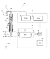
- FIG. 1 is a diagram illustrating a configuration of an inductively coupled plasma analysis system according to an embodiment of the present invention.
- FIG. 2 is a diagram showing the configuration of the droplet device of the present embodiment.
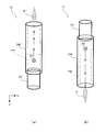
- FIG. 3 is a diagram for explaining the difference between the droplet device of the present embodiment and the reference example.
- FIG. 4 is a diagram illustrating the configuration of the inductively coupled plasma analysis system according to the modification.
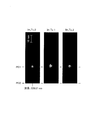
- FIG. 5 is a diagram showing an emission image of metal nanoparticles by the inductively coupled plasma analysis system of the example.
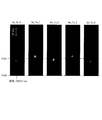
- FIG. 6 is a diagram showing an emission image of metal nanoparticles by an inductively coupled plasma analysis system of a comparative example.
- FIG. 1 is a diagram illustrating the configuration of an inductively coupled plasma analysis system 10 according to this embodiment.
- the inductively coupled plasma analysis system 10 includes a droplet device 12 as a sample supply device, a sample supply control device 14, and a plasma measurement unit 16.
- FIG. 2 is a diagram showing the configuration of the droplet device 12.
- the droplet device 12 functions as a sample supply device that supplies the sample S of the liquid to be measured to the plasma P as sample droplets Sd.
- the droplet device 12 includes a droplet head 20 and a plasma torch 24.
- the droplet head 20 functions as an introduction device that introduces the liquid sample S to be measured in the form of sample droplets Sd.
- the droplet head 20 includes an opening/closing mechanism 20a as a sample discharging mechanism and a sample guide 20b, which are sequentially provided from above in the vertical direction (Y-axis negative direction).
- the opening/closing mechanism 20a is connected to the sample storage container 26 arranged above the droplet device 12 via the sample supply capillary 26a. Then, the opening/closing mechanism 20a opens/closes so as to switch between the blocking state and the passing state of the liquid sample S maintained in the negative pressure state in the sample supply capillary 26a, and the sample droplet Sd is intermittently introduced into the sample guide 20b. To release.
- the opening/closing mechanism 20a expands/contracts so as to intermittently supply the sample droplet Sd to the sample guide 20b at a predetermined cycle (eg, several Hz to several tens of kHz) by adjusting the applied voltage. It is composed of elements.
- a predetermined cycle eg, several Hz to several tens of kHz
- the sample maintained in the negative pressure state in the sample supply capillary 26a is discharged into the sample guide 20b as a sample droplet Sd having a size (diameter) corresponding to the opening/closing cycle of the opening/closing mechanism 20a.
- the sample guide 20b constitutes a sample passage for guiding the sample droplet Sd ejected by the opening/closing mechanism 20a toward the plasma torch 24. More specifically, the sample guide 20b has a tubular shape in which an opening/closing mechanism 20a is attached to the upper part thereof, and a space communicating with the outlet of the sample droplet Sd in the opening/closing mechanism 20a is formed inside. .. A carrier gas introducing passage 20c is provided on the wall of the sample guide 20b.
- the carrier gas introduction passage 20c is a passage for introducing a carrier gas cag that guides the sample droplet Sd in the direction toward the plasma P.
- the carrier gas introduction passage 20c is formed in a notch shape that obliquely intersects the extending direction (vertical direction) of the wall portion of the cylindrical sample guide 20b. That is, the carrier gas introducing passage 20c has a form obliquely intersecting with the wall portion of the sample guide 20b so that the carrier gas cag has a vertically downward flow direction component in the sample guide 20b.
- the sample droplet Sd in the sample guide 20b can be favorably guided in the direction toward the plasma P by the flow of the carrier gas cag.
- the amount of the carrier gas cag introduced from the carrier gas introduction passage 20c can be appropriately adjusted according to factors such as the size (diameter) of the sample droplet Sd.
- the volume flow rate of the carrier gas cag can be set in the range of 0 to 1 liter/min.
- the carrier gas cag it is preferable to use an inert gas from the viewpoint of not hindering stable generation of the plasma P while realizing the function of guiding the sample droplet Sd to the plasma P, and the argon gas is preferable. Is particularly preferably used.
- the plasma P is generated at a position below the droplet head 20 in the vertical direction. Therefore, the sample droplet Sd discharged from the opening/closing mechanism 20a into the sample guide 20b moves downward (Y axis positive direction) in the vertical direction toward the plasma P. Therefore, the sample droplet Sd is guided toward the plasma P by the action of gravity, so that the sample droplet Sd can reach the plasma P favorably without using the carrier gas cag. Therefore, with the configuration of the droplet device 12 of the present embodiment, the volume flow rate of the carrier gas cag can be set in a relatively low range (for example, 0 to 0.1 liter/min).
- the plasma torch 24 is connected to the lower end of the sample guide 20b via a connector 28. Further, the plasma torch 24 is provided with a coil 22 as a plasma generating means for generating the plasma P. The plasma torch 24 is provided with various gas supply passages for stably generating and cooling the plasma P, and also functions as a guide passage for guiding the sample droplet Sd from the sample guide 20b to the plasma P.
- the plasma torch 24 includes a torch body 24a, a sample capillary 24b as a sample passage, and a cooling gas supply passage 24c.
- the torch body 24a is connected at its upper end to the lower end of the sample guide 20b in the droplet head 20 via a connector 28.
- the torch body 24a is formed of a material such as quartz into a substantially cylindrical shape so as to form the sample capillary 24b therein.
- auxiliary gas ag intermediate gas for floating the generated plasma P from the torch body 24a is introduced to the sidewall of the torch body 24a around the sample guide 20b (a relatively upper region in the vertical direction).
- the auxiliary gas introduction pipe 24d is connected.
- the auxiliary gas introduction pipe 24d is connected to the torch body 24a so as to communicate with the space between the torch body 24a and the sample capillary 24b. Therefore, the auxiliary gas ag introduced through the auxiliary gas introduction pipe 24d flows toward the plasma P through the space between the torch body 24a and the sample capillary 24b.
- the amount of the auxiliary gas ag introduced from the auxiliary gas introduction pipe 24d is arbitrary from the viewpoint of the distance from the lower end of the torch body 24a to the plasma P generation position (distance for floating the plasma P). Can be set to.
- the volume flow rate of the auxiliary gas ag can be set within the range of 1 to 1.5 liter/min.
- the auxiliary gas ag it is preferable to use an inert gas having low reactivity from the viewpoint of preventing the stable generation of the plasma P from being hindered while realizing the function of floating the plasma P from the torch body 24a, It is particularly preferable to use argon gas.
- the sample capillary 24b is provided inside the torch body 24a so as to extend from the lower end of the sample guide 20b to the lower end of the coil 22. More specifically, the upper end of the sample capillary 24b communicates with the inside of the sample guide 20b via the connector 28, and the lower end thereof extends in the vertical vertical direction near the upper end of the coil 22. In particular, the length of the sample capillary 24b is set to a predetermined value or more determined from the viewpoint of suppressing the influence of the magnetic field generated by the coil 22 on the droplet head 20.
- the sum of the vertically extended length of the sample guide 20b and the length of the sample capillary 24b (that is, the distance L from the lower end of the opening/closing mechanism 20a to the upper end of the coil 22) is, for example, about several tens cm. It is preferable to configure the sample capillary 24b.
- a cooling gas supply passage 24c for supplying the cooling gas cg (coolant gas) is formed on the outer periphery of the torch body 24a below the auxiliary gas introduction pipe 24d.
- the cooling gas cg is a gas that functions as a shield gas that shields the plasma P from the outside air while cooling the torch body 24a.
- the cooling gas supply passage 24c is made of a material such as quartz, and is a tube that covers a substantially entire area of the torch body 24a in the circumferential direction while ensuring a gap between the outer circumferential surface of the torch body 24a and the cooling gas cg. Formed into a shape.
- the cooling gas cg flows downward in the vertical direction so as to surround the torch body 24a and the sample capillary 24b inside the torch body 24a, so that the cooling function for the torch body 24a and the sample capillary 24b is realized.
- the lower end of the cooling gas supply passage 24c extends downward in the vertical direction beyond the lower end of the torch body 24a. For this reason, the cooling gas cg flows so as to surround the periphery of the plasma P, so that the function of blocking the plasma P from the outside air is preferably realized.
- the amount of the cooling gas cg introduced into the cooling gas supply passage 24c can be arbitrarily set while balancing with the amount of the carrier gas cag according to the state of the plasma P.
- the volumetric flow rate of the cooling gas cg can be set in the range of 12 to 15 liters/min.
- an inert gas having low reactivity is used from the viewpoint of realizing the cooling function of the torch body 24a and the shielding function of the plasma P, and not hindering stable generation of the plasma P. Is preferable, and it is particularly preferable to use argon gas.
- the above-mentioned coil 22 is wound around the cooling gas supply passage 24c.
- the coil 22 receives a supply of AC power from a power supply device (not shown) to generate a magnetic field for generating the plasma P.
- Plasma P is generated by the action of this magnetic field.
- the state of the plasma P can be appropriately adjusted by appropriately adjusting the frequency and the amplitude of the AC power supplied to the coil 22.
- FIG. 3 is a diagram for explaining the operational effects of the droplet device 12 of the present embodiment.
- FIG. 3A is a diagram schematically showing the configuration of the reference example.
- FIG. 3B is a diagram schematically showing the configuration of the droplet device 12 of this embodiment.
- each configuration of the reference example is represented by adding “′” to the reference numeral. Note that, in FIG. 3, the sample guide 20b in the droplet head 20 described above is omitted for simplification of the drawing and description.
- the droplet head 20 ′ is arranged below in the vertical direction, and the plasma P is generated above in the vertical direction. That is, in the configuration of the reference example, the sample droplet Sd′ emitted from the droplet head 20′ from below is supplied to the plasma P′ above via the sample capillary 24b′.
- the sample droplet Sd′ due to gravity is pushed back rather than the thrust in the direction (vertically upward) of the plasma P′ given to the sample droplet Sd′ by the inductive action of the carrier gas cag′.
- the force in the direction (vertical direction) exceeds, and the stable arrival of the sample droplet Sd′ on the plasma P′ may be hindered.
- the thrust in the direction of the plasma P'with respect to the sample droplet Sd' becomes weaker (FIG. 3). (See solid arrow in (a)).
- the sample droplet Sd′ may be displaced in the horizontal direction (x-axis direction) and collide with the wall of the sample capillary 24b′, which may hinder stable arrival at the plasma P′.
- the volume flow rate of the carrier gas cag′ in order to increase the thrust of the sample droplet Sd′ toward the plasma P′.
- the volume flow rate of the carrier gas cag′ also affects the state of the plasma P′, if the volume of the carrier gas cag′ is changed only for the purpose of increasing the thrust of the sample droplet Sd′ in the direction of the plasma P′, a desired plasma is obtained.
- sample droplet Sd′ it may be required to increase the size of the sample droplet Sd′. In that case, since it is necessary to give a larger thrust to the sample droplet Sd′ to reach the plasma P′ stably, it becomes more difficult to stably reach the sample droplet Sd′ to the plasma P′.
- the sample droplet Sd introduced from above by the droplet head 20 is supplied to the plasma P below via the sample capillary 24b. Therefore, the sample droplet Sd is guided to the plasma P by the action of gravity, so that the sample droplet Sd can stably reach the plasma P regardless of the volume flow rate of the carrier gas cag′.
- the sample droplet Sd in the sample capillary 24b is always uniform in the direction toward the plasma P. Thrust can be applied (see the solid arrow in FIG. 3B). Therefore, it is possible to preferably suppress the occurrence of factors that hinder the sample droplet Sd from reaching the plasma P, such as displacement in the horizontal direction (x-axis direction).
- the distance L from the lower end of the opening/closing mechanism 20a to the upper end of the coil 22 is set to a predetermined value or more (see FIG. 2). That is, from the viewpoint of suppressing the influence of the magnetic field generated by the coil 22 on the droplet head 20, the sample capillary 24b is configured to have a certain length.
- the carrier gas cag is ionized in the region near the opening/closing mechanism 20a by the magnetic field, and the action of this ionization causes the carrier gas cag to be discharged near the opening/closing mechanism 20a.
- the sample droplet Sd may be volatilized. When such a phenomenon occurs, the sample droplet Sd cannot be supplied to the plasma P.
- the length of the sample capillary 24 b ′ is set to a certain length or longer, so that the sample droplet Sd′ in the vicinity of the opening/closing mechanism 20 a ′ described above. Volatilization can be suppressed.
- the thrust in the direction of the plasma P′ of the sample droplet Sd′ becomes weaker as the distance from the droplet head 20′ in the sample capillary 24b′ increases. Therefore, if the length of the sample capillary 24b' is increased, the stable arrival of the sample droplet Sd' on the plasma P'is further hindered.
- the sample droplet Sd introduced from the droplet head 20 from above is supplied to the plasma P below, from the lower end of the opening/closing mechanism 20a to the upper end of the coil 22.
- the length of the sample capillary 24b is configured so that the distance L is equal to or greater than a predetermined value. Therefore, regardless of the distance from the droplet head 20, while maintaining the function of stably supplying the sample droplet Sd to the plasma P by the gravity acting uniformly on the sample droplet Sd, Volatilization of the sample droplet Sd in the vicinity can be suppressed.
- the sample supply control device 14 controls the supply of the sample droplet Sd by the droplet device 12.
- the sample supply control device 14 of the present embodiment is composed of a droplet controller 30.
- the droplet controller 30 controls the introduction timing of the sample droplet Sd by the droplet head 20 (opening/closing cycle of the opening/closing mechanism 20a). More specifically, the droplet controller 30 adjusts the applied voltage so that the opening/closing mechanism 20a opens/closes at a desired opening/closing cycle. As a result, the sample droplet Sd is ejected one by one from the droplet head 20 at the supply time interval ⁇ Tf according to the opening/closing cycle of the opening/closing mechanism 20a.
- the plasma measurement unit 16 includes a quartz lens 33, a spectroscope 34, an imaging intensifier 36, a high speed camera 38, and an image analysis device 39.
- the quartz lens 33 focuses the emitted light of the plasma P on the spectroscope 34.
- the quartz lens 33 is configured to collect the emission of the plasma P in the region between the measurement base point PO0 and the measurement end point PO2 (hereinafter, also simply referred to as “measurement region MA”) on the spectroscope 34.
- the spectroscope 34 is composed of, for example, a diffraction grating corresponding to the required wavelength resolution.
- the wavelength resolution of the spectroscope 34 is preferably on the order of 1/100 nm, for example, 0.04 nm or less.
- the imaging intensifier 36 amplifies the light decomposed by the spectroscope 34 and generates a spatial distribution of the light. More specifically, the imaging intensifier 36 detects the light dispersed by the spectroscope 34 as a two-dimensional image corresponding to the spatial distribution (vertical position and horizontal position) of the measurement area MA.
- the high-speed camera 38 functions as an image generation unit that captures a two-dimensional image detected by the imaging intensifier 36 and generates a time-series image Im(Tu). More specifically, the high-speed camera 38 continuously captures the two-dimensional image at preset measurement unit time Tu (for example, several tens ⁇ s to several hundreds ⁇ s) to generate a time-series image Im(Tu). , The time-series image Im(Tu) is saved as digital data. Therefore, the high-speed camera 38 is configured to be able to set a frame rate (for example, tens of thousands to hundreds of thousands of fps) capable of realizing continuous shooting for each measurement unit time Tu.
- a frame rate for example, tens of thousands to hundreds of thousands of fps
- the shooting time interval (measurement unit time Tu) of the high-speed camera 38 sufficiently smaller than the supply time interval ⁇ Tf (opening/closing cycle of the opening/closing mechanism 20a) of the sample droplet Sd. ..
- the photographing time interval (measurement unit time Tu) of the high-speed camera 38 at least the time during which the sample droplet Sd passes through the measurement area MA (the sample droplet Sd reaches the measurement end point PO2 after entering the measurement area MA). It is preferable to set the time shorter than the time required to do so.
- the high-speed camera 38 is provided so that one or more sample droplets Sd supplied from the droplet device 12 can acquire images of a predetermined number or more of the sample droplets Sd while moving in the measurement area MA. It is particularly preferable to set the photographing time interval (measurement unit time Tu).
- the photographing time interval (measurement unit time Tu) is set so that several to several hundred images of the sample droplet Sd can be acquired while the sample droplet Sd is moving in the measurement area MA. be able to. From this viewpoint, for example, it is preferable to set the photographing time interval (measurement unit time Tu) to about 1/100 to 1/10000 times the supply time interval ⁇ Tf.
- the vertical image coordinates of the time series image Im correspond to the vertical position of the measurement area MA
- the horizontal image coordinates of the time series image Im correspond to the position corresponding to the wavelength component ⁇ k. Therefore, hereinafter, the image coordinates of the time-series image Im are represented by the same symbols (x, y) as the vertical direction (y-axis direction) and the horizontal direction (x-axis direction) in the measurement area MA.
- the image analysis device 39 analyzes each time series image Im generated as digital data by the high-speed camera 38, and measures time t and each time of each time series image Im according to the measurement unit time Tu. It functions as an image analysis means for obtaining the light intensity distribution Ind(t,x,y) with the image coordinates (x,y) on the series image Im as a variable.
- the image analysis device 39 integrates the light intensity distribution Ind(t,x,y) over the entire range of the image coordinate y, ie, the wavelength-time intensity distribution Ind_1(t,x) or the light intensity distribution Ind(t,x). , y) may be integrated at the image coordinate x to calculate the position-time intensity distribution Ind_2(t, y). Furthermore, the image analysis device 39 may be configured to calculate a total time intensity distribution Ind_all(t) obtained by integrating the light intensity distribution Ind(t,x,y) at both the image coordinate y and the image coordinate x. ..
- the droplet device 12 of the present embodiment is provided with a droplet head 20 as an introducing device for intermittently introducing a sample (sample droplet Sd) and a coil 22 as a plasma generating means for generating plasma P, and introducing the same.
- the droplet head 20 is provided above the plasma torch 24, and the coil 22 is provided below the plasma torch 24.
- the sample droplet Sd is introduced from the vertically upper portion of the plasma torch 24 via the droplet head 20, and the plasma generated by the coil 22 provided at the vertically lower portion of the plasma torch 24 by the action of gravity. It is guided in the direction toward P. That is, since the movement of the sample droplet Sd emitted by the droplet head 20 to the plasma P is promoted by the action of gravity, the sample droplet Sd can stably reach the plasma P.
- the droplet device 12 of the present embodiment by utilizing the action of gravity, it is possible to apply a constant thrust to the plasma P to the sample droplet Sd regardless of its mass. .. Therefore, even the sample droplet Sd having a large size (diameter) to the extent that the stable arrival at the plasma P cannot be realized only by the inductive action by the carrier gas cag, the stable arrival at the plasma P can be achieved. it can. As a result, the size range of the sample droplet Sd applicable to the droplet device 12 can be further expanded by increasing the diameter of the hole through which the sample droplet Sd passes in the opening/closing mechanism 20a of the droplet head 20. it can.
- the action of inducing the sample droplet Sd into the plasma P by gravity can be obtained, so that the amount of the carrier gas cag can be reduced. That is, until now, it was required to introduce a certain amount or more of the carrier gas cag in order to obtain the function of guiding the sample, but with the configuration of this embodiment, this function is realized by the action of gravity.
- the volume flow rate of the carrier gas cag can be set to a lower value.
- the volumetric flow rate of the carrier gas cag is a parameter that also affects the state of the generated plasma P. That is, if the volumetric flow rate of the carrier gas cag can be set freely, the plasma P can be generated more easily. Then, as described above, with the configuration of the present embodiment, even if the volume flow rate of the carrier gas cag is set to a lower value as described above, the function of inducing the sample droplet Sd into the plasma P is impaired. Absent. Therefore, the volumetric flow rate of the carrier gas cag can be set in a low value range with a relatively high degree of freedom, and the stable plasma P can be generated more easily.
- the sample droplet Sd may be guided to the plasma P only by the action of gravity without supplying the carrier gas cag.
- the sample droplet Sd may be supplied to the plasma P and the analysis can be performed without consuming the carrier gas cag.
- the cost in the analysis can be reduced because the carrier gas cag is not supplied.
- the distance L from the droplet head 20 to the coil 22 is equal to or more than a predetermined value determined from the viewpoint of suppressing the influence of the magnetic field generated by the coil 22 on the droplet head 20. Is set to.
- the droplet head 20 is caused by a magnetic field generated by the coil 22 such as volatilization of the sample droplet Sd in the vicinity of the opening/closing mechanism 20a.
- the adverse effect of can be suppressed.
- the droplet head 20 includes an opening/closing mechanism 20a as a sample discharging mechanism that discharges the sample droplet Sd toward the plasma torch 24 in a predetermined cycle.
- the operation of allowing the sample droplets Sd to reach the plasma P stably. can be realized.
- the plasma torch 24 includes a torch body 24a connected to the lower end of the droplet head 20 and at least the coil 22 from the lower end of the droplet head 20 to the inside of the torch body 24a.
- a sample capillary 24b as a sample passage extending in the up-and-down direction, and a cooling gas cg which is formed around the torch body 24a along the extending direction of the sample capillary 24b and which causes a cooling gas cg to flow downward along the torch body 24a.
- a gas supply path 24c is a gas supply path 24c.
- the torch body 24a and the sample capillary 24b can be suitably cooled by the cooling gas cg through the cooling gas supply passage 24c.
- the cooling gas cg flows downward (that is, in the direction toward the plasma P) in the cooling gas supply passage 24c, the heat rise from the plasma P can be prevented by the flow of the cooling gas cg. Therefore, the cooling effect of the torch body 24a and the sample capillary 24b can be more effectively exhibited.
- the droplet device 12 having the above configuration, the droplet controller 30 and the pulse generator 32 as the introduction control device for controlling the droplet head 20, and the plasma as the measuring device for measuring the state of the plasma P.
- An inductively coupled plasma analysis system 10 including a measurement unit 16 is provided.
- the state (light emission) of the plasma P to which the sample droplet Sd is stably supplied by the droplet device 12 of the present embodiment can be measured. That is, the state of the plasma P resulting from atomization or ionization of the sample droplet Sd can be detected more reliably. As a result, the accuracy of analysis (particularly spectrum analysis) of the sample droplet Sd based on the measured state of the plasma P can be further improved. Further, in this embodiment, as described above, the range of the sample droplet Sd applicable to the droplet device 12 is expanded. Therefore, in the inductively coupled plasma analysis system 10 including the droplet device 12, it is possible to measure the sample droplet Sd in a wider range of sizes, and as a result, it is possible to analyze a wider variety of substances.
- a sample supply method executed by the droplet device 12 is provided.
- the present embodiment provides a sample supply method of supplying a sample droplet Sd as a sample to be measured to the plasma P via the plasma torch 24.
- the plasma P is generated at a position lower than the plasma torch 24, and the sample droplet Sd is introduced from a position higher than the plasma torch 24.
- the introduced sample droplet Sd is guided in the direction toward the plasma P by the action of gravity. That is, since the thrust force toward the plasma P is applied to the sample droplet Sd by gravity, the sample droplet Sd can reach the plasma P stably.
- a pulse generator 32 that generates a synchronization signal that synchronizes the supply timing of the sample droplet Sd from the droplet device 12 and the measurement timing of the emission state of the plasma P and outputs the synchronization signal to the droplet controller 30.
- the droplet controller 30 may open/close the opening/closing mechanism 20a at an opening/closing cycle according to the synchronization signal to control the supply timing of the sample droplet Sd from the droplet device 12.
- the measurement timing is set so that the light emission state of the plasma P that reflects the influence of the excitation of the sample droplet Sd after one sample droplet Sd reaches the light emission start point PO1 can be more reliably performed. be able to. As a result, it is possible to more reliably measure the change over time in the light emitting state of the plasma P according to the time progress of the excitation of the same sample droplet Sd.
- the present invention is not limited to this, and a configuration for supplying a solid or gel sample or the like may be adopted.
- the sample can be introduced in the form of particles without using the opening/closing mechanism 20a, a drop provided with an arbitrary mechanism for introducing the sample particles one by one instead of the opening/closing mechanism 20a.
- the let head 20 may be adopted. Since the solid or gel sample generally has a higher density than the sample droplet Sd, the mass tends to increase even with the same size.
- the stable arrival to the plasma P may be further impaired as compared with the case of the sample droplet Sd.
- the thrust force in the direction toward the plasma P is applied to the sample by the action of gravity, it is a sample having a relatively large mass such as a solid or gel sample.
- the same thrust as in the case of the sample droplet Sd can be applied. That is, even a solid or gel sample can reach the plasma P stably, and the accuracy of the subsequent analysis can be improved.
- the inductively coupled plasma analysis system 10 including the droplet device 12 has a configuration in which so-called inductively coupled plasma emission analysis is assumed as the inductively coupled plasma analysis.
- the droplet device 12 of the present embodiment can also be adopted in a system that performs inductively coupled plasma mass spectrometry.
- time series image Im_Tu of the emission of the plasma P the time series image Im_Tu_0 at the timing when one sample droplet Sd reaches the vicinity of the light emission start point PO1, and the supply of the sample droplet Sd from the time series image Im_Tu_0
- a time series image Im_Tu_1 and a time series image Im_Tu_2 generated at timings substantially corresponding to the respective cycle timings in two cycles are extracted.
- the extracted time series images Im_Tu_0 to Im_Tu_2 are shown in FIG.
- the time series image Im_Tu_0′ at the timing when one sample droplet Sd′ reaches the vicinity of the light emission start point PO1′, the time series image Im_Tu_0′, and the sample FIG. 6 shows time-series images Im_Tu_1 to Im_Tu_4 generated at timings substantially coincident with the respective cycle timings in the five supply cycles of the droplet Sd.
- the timings at which the sample droplets Sd reach the light emission start point PO1 are substantially coincident with each other. That is, in the example, it is considered that the sample droplet Sd′ is more stably guided to the plasma P than in the comparative example.
Landscapes
- Physics & Mathematics (AREA)
- Engineering & Computer Science (AREA)
- Plasma & Fusion (AREA)
- Health & Medical Sciences (AREA)
- Analytical Chemistry (AREA)
- Nuclear Medicine, Radiotherapy & Molecular Imaging (AREA)
- Life Sciences & Earth Sciences (AREA)
- Chemical & Material Sciences (AREA)
- Spectroscopy & Molecular Physics (AREA)
- Biochemistry (AREA)
- General Health & Medical Sciences (AREA)
- General Physics & Mathematics (AREA)
- Immunology (AREA)
- Pathology (AREA)
- Investigating, Analyzing Materials By Fluorescence Or Luminescence (AREA)
- Plasma Technology (AREA)
Abstract
試料を間欠的に導入する導入装置と、プラズマを生成するプラズマ生成手段が設けられるとともに導入された試料をプラズマに誘導するプラズマトーチと、を備える試料供給装置であって、プラズマトーチの上部に導入装置を設け、プラズマトーチの下部にプラズマ生成手段を設ける。
Description
本発明は、試料供給装置、該試料供給装置を含む誘導結合プラズマ分析システム、及び試料供給方法に関する。
誘導結合プラズマ(ICP:Inductively Coupled Plasma)のようなプラズマを原子化源またはイオン化源に用いた発光分析装置または質量分析装置は、材料分析、環境分析、少量分析等の幅広い分野における汎用性の高い高感度元素分析装置として知られている。
誘導結合プラズマ発光分析装置や誘導結合プラズマ質量分析装置(以下では、これらを総称して「誘導結合プラズマ分析システム」と記載する)では、液体状の試料をプラズマ源に供給してプラズマ化(励起)させ、プラズマからの発光やイオン化された試料に基づいて分析を行う。
WO2006/137205には、プラズマトーチにおけるプラズマが生じる部分に、試料としての液滴を供給する噴霧装置を備えたプラズマ装置が提案されている。このプラズマ装置における噴霧装置には、液滴を間欠的に噴出するアクチュエータとして、印加される電圧に応じてノズルの噴出口径を調節するピエゾ素子が設けられている。このプラズマ装置において、ノズルから噴出された試料をキャリアガスの作用によりプラズマに誘導する。
しかしながら、特許文献1のプラズマ装置において、キャリアガスの作用では液滴をプラズマ部分まで到達させるほどの安定的な推力が得られがたい場合があった。特に、試料としての液滴のサイズが大きい場合には、試料をプラズマ部分に安定的に到達させることがより難しくなるという問題がある。
このような事情に鑑み、本発明の目的は、測定対象の試料を安定的にプラズマに到達させることのできる試料供給装置を提供することにある。
本発明のある態様によれば、試料を間欠的に導入する導入装置と、プラズマを生成するプラズマ生成手段が設けられるとともに導入された試料をプラズマに誘導するプラズマトーチと、を備えた試料供給装置が提供される。
そして、この試料供給装置では、プラズマトーチの上部に導入装置が設けられ、プラズマトーチの下部にプラズマ生成手段が設けられる。
以下、図面等を参照して、本発明の実施形態について説明する。
図1は、本実施形態による誘導結合プラズマ分析システム10の構成を説明する図である。図示のように、誘導結合プラズマ分析システム10は、試料供給装置としてのドロップレット装置12と、試料供給制御装置14と、プラズマ測定ユニット16と、を有している。
図2は、ドロップレット装置12の構成を示す図である。ドロップレット装置12は、測定対象となる液体の試料Sを試料液滴SdとしてプラズマPに供給する試料供給装置として機能する。図示のように、ドロップレット装置12は、ドロップレットヘッド20と、プラズマトーチ24と、を備える。
ドロップレットヘッド20は、測定対象となる液体の試料Sを試料液滴Sdの形態にして導入する導入装置として機能する。ドロップレットヘッド20は、鉛直方向の上方(Y軸負方向)から順に設けられた、試料放出機構としての開閉機構20aと、試料ガイド20bと、を備えている。
開閉機構20aは、ドロップレット装置12の上方に配置される試料貯留容器26に試料供給キャピラリ26aを介して接続される。そして、開閉機構20aは、試料供給キャピラリ26a内で負圧状態に維持されている液体の試料Sの遮断状態と通過状態を切り替えるように開閉し、試料液滴Sdを試料ガイド20b内に間欠的に放出する。
より詳細には、開閉機構20aは、印加電圧を調整することにより試料ガイド20bに試料液滴Sdを所定周期(例えば数Hz~数十kHz)で間欠的に供給するように拡大・収縮するピエゾ素子などによって構成される。この構成により、試料供給キャピラリ26a内で負圧状態に維持されている試料は、開閉機構20aにおける開閉周期に応じたサイズ(径)の試料液滴Sdとして試料ガイド20b内に放出される。
試料ガイド20bは、開閉機構20aにより噴出される試料液滴Sdをプラズマトーチ24の方向へ誘導するための試料通路を構成する。より詳細には、試料ガイド20bは、その上部に開閉機構20aが取り付けられるとともに、当該開閉機構20aにおける試料液滴Sdの放出口と連通する空間が内部に形成された筒状に構成されている。また、試料ガイド20bの壁部にはキャリアガス導入路20cが設けられている。
キャリアガス導入路20cは、試料液滴SdをプラズマPに向かう方向に誘導するキャリアガスcagを導入するための通路である。キャリアガス導入路20cは、筒状の試料ガイド20bの壁部の伸長方向(鉛直方向)に対して斜めに交差する切欠き状に形成されている。すなわち、キャリアガス導入路20cは、キャリアガスcagが試料ガイド20b内において鉛直方向下向きの流れ方向成分を持つように、試料ガイド20bの壁部に対して斜交する形態をとる。
したがって、このキャリアガス導入路20cを介してキャリアガスcagを流すことで、当該キャリアガスcagの流れで試料ガイド20b内の試料液滴SdをプラズマPに向かう方向へ好適に誘導することができる。
なお、キャリアガス導入路20cから導入するキャリアガスcagの量は、試料液滴Sdのサイズ(径)などの要素に応じて適宜調節することができる。例えば、キャリアガスcagの体積流量を、0~1リットル/minの範囲に設定することができる。また、キャリアガスcagとしては、試料液滴SdをプラズマPへ誘導する機能を実現しつつ、プラズマPの安定的な生成を阻害しないようにする観点から不活性ガスを用いることが好ましく、アルゴンガスを用いることが特に好ましい。
また、後に詳細に説明するが、本実施形態のドロップレット装置12の構成では、ドロップレットヘッド20に対して鉛直方向における下方位置にプラズマPが生成されることとなる。そのため、開閉機構20aから試料ガイド20b内に放出される試料液滴Sdは、プラズマPに向かって鉛直方向における下方(Y軸正方向)に移動することとなる。したがって、試料液滴Sdは重力の作用でプラズマPに向かう方向へ誘導されるので、キャリアガスcagを用いずとも、試料液滴SdをプラズマPに好適に到達させることができる。このため、本実施形態のドロップレット装置12の構成であれば、キャリアガスcagの体積流量を比較的低い範囲(例えば、0~0.1リットル/min)に設定することもできる。
一方、プラズマトーチ24は接続体28を介して試料ガイド20bの下端に接続されている。また、プラズマトーチ24にはプラズマPを生成するプラズマ生成手段としてのコイル22が設けられている。プラズマトーチ24は、プラズマPの安定的生成及び冷却を行うための各種ガスの供給通路を備えるとともに、試料ガイド20bからの試料液滴SdをプラズマPに誘導する誘導路として機能する。
より詳細に、プラズマトーチ24は、トーチ本体24aと、試料通路としての試料キャピラリ24bと、冷却ガス供給路24cと、を備えている。
トーチ本体24aは、その上端が接続体28を介してドロップレットヘッド20における試料ガイド20bの下端と接続されている。トーチ本体24aは、例えば、石英などの材料により内部に試料キャピラリ24bを構成するように略円筒形状に形成される。
さらに、トーチ本体24aの側壁には、試料ガイド20bの周辺(鉛直方向における比較的上部の領域)において、生成されるプラズマPをトーチ本体24aから浮かせるための補助ガスag(中間ガス)を導入する補助ガス導入管24dが接続されている。
より詳細には、補助ガス導入管24dは、トーチ本体24aと試料キャピラリ24bとの間の空間に連通するようにトーチ本体24aに接続されている。したがって、補助ガス導入管24dを介して導入される補助ガスagは、トーチ本体24aと試料キャピラリ24bとの間を介してプラズマPに向かって流れることとなる。
なお、補助ガス導入管24dから導入される補助ガスagの量は、トーチ本体24aの下端からプラズマPの生成位置までの距離(プラズマPを浮かせる距離)をどの程度とするかなどの観点から任意に設定することができる。例えば、補助ガスagの体積流量を1~1.5リットル/minの範囲で設定することができる。また、補助ガスagとしては、プラズマPをトーチ本体24aから浮かせる機能を実現しつつ、プラズマPの安定的な生成を阻害しないようにする観点から反応性が低い不活性ガスを用いることが好ましく、アルゴンガスを用いることが特に好ましい。
そして、試料キャピラリ24bは、トーチ本体24aの内部において、試料ガイド20bの下端からコイル22の下端に亘って伸長するように設けられている。より詳細には、試料キャピラリ24bは、その上端が接続体28を介して試料ガイド20b内と連通するとともに、下端がコイル22上端近傍へ鉛直上下方向に伸長する。特に、試料キャピラリ24bの長さは、コイル22により生じる磁場によるドロップレットヘッド20への影響を抑制する観点から定まる所定値以上に設定される。このため、試料ガイド20bの鉛直方向における伸長長さと試料キャピラリ24bの長さの和(すなわち、開閉機構20aの下端からコイル22の上端までの距離L)が例えば、数十cm程度となるように試料キャピラリ24bを構成することが好ましい。
また、補助ガス導入管24dよりも下方におけるトーチ本体24aの外周には、冷却ガスcg(クーラントガス)を供給するための冷却ガス供給路24cが構成されている。なお、冷却ガスcgは、トーチ本体24aを冷却しつつ、プラズマPを外気から遮断するシールドガスとして機能するガスである。
特に、冷却ガス供給路24cは、石英などの材料で構成され、トーチ本体24aの外周面との間で冷却ガスcgが流れる間隙を確保しつつ、当該トーチ本体24aの周方向略全域を覆う筒状に形成される。これにより、冷却ガスcgがトーチ本体24a及びその内部の試料キャピラリ24bを外周から囲うように鉛直方向の下方向に向かって流れるため、トーチ本体24a及び試料キャピラリ24bに対する冷却機能が実現される。さらに、冷却ガス供給路24cの下端は、トーチ本体24aの下端を越えてより鉛直方向の下方へ伸長している。このため、冷却ガスcgがプラズマPの周囲を囲むように流れるので、プラズマPを外気から遮断する機能が好適に実現される。
なお、冷却ガス供給路24cに導入される冷却ガスcgの量は、プラズマPの状態に応じてキャリアガスcagの量とのバランスをとりつつ任意に設定することができる。例えば、冷却ガスcgの体積流量を12~15リットル/minの範囲に設定することができる。また、冷却ガスcgとしては、トーチ本体24aの冷却機能及びプラズマPのシールド機能を実現しつつ、プラズマPの安定的な生成を阻害しないようにする観点から反応性が低い不活性ガスを用いることが好ましく、アルゴンガスを用いることが特に好ましい。
さらに、プラズマトーチ24の下端付近の位置において、冷却ガス供給路24cの外周に上述したコイル22が巻回されている。コイル22は、図示しない電力供給装置からの交流電力の供給を受けることでプラズマPを生成するための磁場を発生させる。この磁場の作用によりプラズマPが生成される。なお、コイル22に供給する交流電力の周波数及び振幅などを適宜調節することで、プラズマPの状態を適宜調節することができる。
次に、上記構成を有するドロップレット装置12の作用効果を参考例と対比しつつ説明する。
図3は、本実施形態のドロップレット装置12の作用効果を説明する図である。特に、図3(a)は参考例の構成を模式的に示す図である。また、図3(b)は本実施形態のドロップレット装置12の構成を模式的に示す図である。なお、図3(a)は参考例の各構成は符号に「´」を付して表す。なお、図3では図面及び説明の簡略化のため、上述したドロップレットヘッド20における試料ガイド20bを省略する。
図示のように、参考例のドロップレット装置12´では、鉛直方向における下方にドロップレットヘッド20´が配置され、鉛直方向における上方にプラズマPが生成される構成をとっている。すなわち、参考例の構成では、下方からドロップレットヘッド20´により放出された試料液滴Sd´が、試料キャピラリ24b´を介して上方のプラズマP´に供給されることとなる。
しかしながら、この参考例の構成の場合、キャリアガスcag´による誘導作用によって試料液滴Sd´に与えられるプラズマP´の方向(鉛直上方)への推力よりも、重力による試料液滴Sd´を押し戻す方向(鉛直方向)の力が上回り、試料液滴Sd´のプラズマP´への安定的な到達が阻害されることがある。特に、試料液滴Sd´が試料キャピラリ24b´内においてドロップレットヘッド20´から離れてプラズマP´に近づくほど、当該試料液滴Sd´に対するプラズマP´の方向への推力が弱くなる(図3(a)の実線矢印参照)。これにより、試料液滴Sd´が水平方向(x軸方向)に変位して試料キャピラリ24b´の壁部に衝突するなどして、プラズマP´へ安定的な到達が阻害されることがある。
ここで、試料液滴Sd´のプラズマP´の方向への推力を高めるべく、キャリアガスcag´の体積流量をより大きくすることも考えられる。しかしながら、キャリアガスcag´の体積流量はプラズマP´の状態にも影響を及ぼすため、試料液滴Sd´のプラズマP´の方向への推力を高めるという目的のみでこれを変更すると、所望のプラズマP´の状態を得るために他のパラメータ(コイル22の印加電圧や冷却ガスcgの体積流量)に対する設定も必要となり、煩雑な作業が要求される。
さらに、測定対象となる試料S´の種類などによって、試料液滴Sd´のサイズをより大きくすることが求められる場合もある。その場合、試料液滴Sd´をプラズマP´に安定的に到達させるためにより大きな推力を与える必要となるため、試料液滴Sd´をプラズマP´へ安定的に到達させることがより難しくなる。
これに対して、本実施形態のドロップレット装置12では、ドロップレットヘッド20により上方から導入された試料液滴Sdが、試料キャピラリ24bを介して下方のプラズマPに供給されることとなる。したがって、試料液滴Sdが重力の作用でプラズマPに誘導されることとなるため、キャリアガスcag´の体積流量に関らず試料液滴SdをプラズマPに安定的に到達させることができる。
特に、重力の作用は試料キャピラリ24b内の任意の位置において試料液滴Sdに一様に作用するので、試料キャピラリ24b内の試料液滴Sdに対して常にプラズマPに向かう方向への一様な推力を与えることができる(図3(b)の実線矢印参照)。このため、試料液滴Sdの水平方向(x軸方向)への変位などのプラズマPへの到達を阻害する要因の発生を好適に抑制することができる。
また、本実施形態のドロップレット装置12では、上述のように、開閉機構20aの下端からコイル22の上端までの距離Lが所定値以上に設定される(図2参照)。すなわち、コイル22により生じる磁場によるドロップレットヘッド20への影響を抑制する観点から試料キャピラリ24bがある程度の長さに構成される。
ここで、コイル22により生じる磁場によるドロップレットヘッド20への影響の一例としては、上記磁場によってキャリアガスcagが開閉機構20aの近傍領域で電離し、この電離の作用によって当該開閉機構20aの近傍において試料液滴Sdが揮発することが挙げられる。このような現象が発生すると、試料液滴SdをプラズマPへ供給することができなくなる。
一方、図3(a)に示す参考例のドロップレット装置12´において、試料キャピラリ24b´の長さを一定以上に構成することで、上述した開閉機構20a´の近傍における試料液滴Sd´の揮発を抑制することはできる。しかしながら、この参考例の構成では、試料キャピラリ24b´内においてドロップレットヘッド20´から離れるほど、試料液滴Sd´のプラズマP´の方向への推力が弱くなる。このため、試料キャピラリ24b´の長さを長くすると、試料液滴Sd´のプラズマP´への安定的な到達がより一層阻害されることになる。
これに対して、本実施形態では、上方からドロップレットヘッド20により導入された試料液滴Sdを下方のプラズマPに供給する構成を前提としつつ、開閉機構20aの下端からコイル22の上端までの距離Lが所定値以上となるように試料キャピラリ24bの長さを構成している。このため、ドロップレットヘッド20からの距離に関らず、試料液滴Sdに一様に作用する重力によって試料液滴SdをプラズマPに安定的な供給する機能を維持しつつ、開閉機構20aの近傍における試料液滴Sdの揮発を抑制することができる。
次に、図1に戻り、試料供給制御装置14及びプラズマ測定ユニット16の構成について説明する。試料供給制御装置14は、ドロップレット装置12による試料液滴Sdの供給を制御する。本実施形態の試料供給制御装置14は、ドロップレットコントローラ30により構成される。
ドロップレットコントローラ30は、ドロップレットヘッド20による試料液滴Sdの導入タイミング(開閉機構20aの開閉周期)を制御する。より詳細には、ドロップレットコントローラ30は、開閉機構20aが所望の開閉周期で開閉するように印加電圧を調節する。これにより、試料液滴Sdは、開閉機構20aの開閉周期に応じた供給時間間隔ΔTfでドロップレットヘッド20から一滴ずつ放出される。
プラズマ測定ユニット16は、石英レンズ33と、分光器34と、イメージングインテンシファイア36と、高速度カメラ38と、画像解析装置39と、を備えている。
石英レンズ33は、プラズマPの発光を分光器34へ集光する。特に、石英レンズ33は、測定基点PO0から測定終点PO2の間の領域(以下、単に「測定領域MA」とも称する)におけるプラズマPの発光を分光器34に集光するように構成される。
分光器34は、石英レンズ33で集光された光を波長成分λk(k=1,2,3・・・)ごとの光に分解する。より詳細には、分光器34は、石英レンズ33で集光された光を、その波長成分λ1、λ2、λ3・・・がy軸方向に沿って並ぶように結像する。分光器34は、例えば、要求される波長分解能に応じた回折格子により構成される。なお、分光器34の波長分解能は1/100nmオーダー、例えば0.04nm以下であることが好ましい。
イメージングインテンシファイア36は、分光器34により分解された光を増幅しつつ該光の空間分布を生成する。より詳細には、イメージングインテンシファイア36は、分光器34で分光された光を測定領域MAの空間分布(鉛直方向位置及び水平方向位置)に対応させた2次元イメージとして検出する。
高速度カメラ38は、イメージングインテンシファイア36によって検出された2次元イメージを撮影して時系列画像Im(Tu)を生成する画像生成手段として機能する。より詳細に、高速度カメラ38は、予め設定される測定単位時間Tu(例えば数十μs~数百μs)ごとに、上記2次元イメージを連続撮影して時系列画像Im(Tu)を生成し、当該時系列画像Im(Tu)をデジタルデータとして保存する。したがって、高速度カメラ38は、上記測定単位時間Tuごとの連続撮影を実現できるフレームレート(例えば、数万~数十万fps)を設定可能に構成される。
なお、本実施形態では、高速度カメラ38の撮影時間間隔(測定単位時間Tu)を、試料液滴Sdの供給時間間隔ΔTf(開閉機構20aの開閉周期)よりも十分に小さく設定することが好ましい。特に、高速度カメラ38の撮影時間間隔(測定単位時間Tu)を、少なくとも試料液滴Sdが測定領域MAを通過する時間(試料液滴Sdが測定領域MAに突入してから測定終点PO2に到達するまでにかかる時間)よりも短く設定することが好ましい。さらに、ドロップレット装置12から供給される一滴の試料液滴Sdが測定領域MA中を移動している過程で当該試料液滴Sdの所定数以上の画像を取得できるように、高速度カメラ38の撮影時間間隔(測定単位時間Tu)を設定することが特に好ましい。例えば、試料液滴Sdが測定領域MA中を移動している過程で当該試料液滴Sdの画像を数コマ~数百コマ取得できるように、上記撮影時間間隔(測定単位時間Tu)を設定することができる。この観点から、例えば、撮影時間間隔(測定単位時間Tu)を、供給時間間隔ΔTfの1/100~1/10000倍程度に設定することが好ましい。
ここで、時系列画像Imの縦方向の画像座標は測定領域MAの鉛直方向における位置に相当し、時系列画像Imの横方向の画像座標は波長成分λkに応じた位置に相当する。したがって、以下では、時系列画像Imの画像座標を、測定領域MAにおける鉛直方向(y軸方向)及び水平方向(x軸方向)と同様の符号(x,y)で表す。
図1に戻り、画像解析装置39は、高速度カメラ38によりデジタルデータとして生成された各時系列画像Imを解析し、測定単位時間Tuに応じた各時系列画像Imの測定時刻t及び各時系列画像Im上の画像座標(x,y)を変数とした光強度分布Ind(t,x,y)を求める画像解析手段として機能する。
なお、画像解析装置39は、光強度分布Ind(t,x,y)を画像座標yの全範囲で積分した波長-時間強度分布Ind_1(t,x)、又は光強度分布Ind(t,x,y)を画像座標xで積分した位置-時間強度分布Ind_2(t,y)を演算するように構成しても良い。さらに、画像解析装置39は、光強度分布Ind(t,x,y)を画像座標y及び画像座標xの双方で積分したトータル時間強度分布Ind_all(t)を演算するように構成しても良い。
以上、説明した本実施形態のドロップレット装置12又は誘導結合プラズマ分析システム10の構成によれば、以下の作用効果を奏する。
本実施形態のドロップレット装置12は、試料(試料液滴Sd)を間欠的に導入する導入装置としてのドロップレットヘッド20と、プラズマPを生成するプラズマ生成手段としてのコイル22が設けられるとともに導入された試料液滴SdをプラズマPに誘導するプラズマトーチ24と、を備える。
そして、このドロップレット装置12では、プラズマトーチ24の上部にドロップレットヘッド20が設けられ、プラズマトーチ24の下部にコイル22が設けられる。
これにより、試料液滴Sdがドロップレットヘッド20を介してプラズマトーチ24の鉛直方向の上部から導入され、重力の作用でプラズマトーチ24の鉛直方向の下部に設けられたコイル22により生成されるプラズマPに向かう方向に誘導される。すなわち、ドロップレットヘッド20により放出された試料液滴SdのプラズマPへの移動が重力の作用で促進されることとなるため、試料液滴SdをプラズマPに安定的に到達させることができる。
特に、本実施形態のドロップレット装置12の構成であれば、重力の作用を利用することで、試料液滴Sdに対してその質量に関らず一定にプラズマPへの推力を与えることができる。このため、キャリアガスcagによる誘導作用のみでは、プラズマPへの安定的な到達が実現できない程度にサイズ(径)の大きい試料液滴Sdであっても、安定的にプラズマPへ到達させることができる。結果として、ドロップレットヘッド20の開閉機構20aにおいて試料液滴Sdを通す孔の径をより大きくするなどして、ドロップレット装置12に適用できる試料液滴Sdのサイズの範囲をより拡大することができる。
また、本実施形態のドロップレット装置12の構成であれば、重力により試料液滴SdをプラズマPに誘導する作用が得られるため、キャリアガスcagの量を減少させることができる。すなわち、これまでは、試料を誘導する機能を得るために一定量以上のキャリアガスcagを導入することが求められていたが、本実施形態の構成であればこの機能が重力の作用で実現されているところ、キャリアガスcagの体積流量をより低い値に設定することができる。
なお、キャリアガスcagの体積流量は生成されるプラズマPの状態にも影響を与えるパラメータである。すなわち、キャリアガスcagの体積流量を自由に設定できれば、プラズマPの生成がより容易となる。そして、上述のように、本実施形態の構成であれば、上述のようにキャリアガスcagの体積流量をより低い値に設定したとしても、試料液滴SdをプラズマPに誘導する機能が損なわれない。このため、キャリアガスcagの体積流量を低い値の範囲で比較的高い自由度をもって設定することができ、より容易に安定的なプラズマPを生成することができる。
さらに、状況に応じて、キャリアガスcagを供給することなく、重力の作用のみで試料液滴SdをプラズマPに誘導するようにしても良い。この場合には、例えば、キャリアガスcagの体積流量を0に設定することで、キャリアガスcagを消費することなく試料液滴SdをプラズマPに供給してその分析を行うことができる。結果として、キャリアガスcagを供給しない分、分析におけるコストを低減することができる。
また、本実施形態のドロップレット装置12では、ドロップレットヘッド20からコイル22までの間の距離Lは、該コイル22により生じる磁場によるドロップレットヘッド20への影響を抑制する観点から定まる所定値以上に設定される。
これにより、試料液滴SdをプラズマPに安定的な供給する機能を維持しつつも、開閉機構20aの近傍における試料液滴Sdの揮発などのコイル22によって生じる磁場に起因したドロップレットヘッド20への悪影響を抑制することができる。
また、本実施形態のドロップレット装置12では、ドロップレットヘッド20は、試料液滴Sdをプラズマトーチ24に向けて所定周期で放出する試料放出機構としての開閉機構20aを備える。
すなわち、本実施形態では、所定周期で間欠的に試料液滴SdをプラズマPへ供給するタイプの装置(いわゆるドロップレットシステム)において、試料液滴SdをプラズマPに安定的に到達させるという作用を実現することができる。
さらに、本実施形態のドロップレット装置12では、プラズマトーチ24は、ドロップレットヘッド20の下端に接続されるトーチ本体24aと、トーチ本体24aの内部において、ドロップレットヘッド20の下端から少なくともコイル22に亘って上下方向に伸長する試料通路としての試料キャピラリ24bと、試料キャピラリ24bの伸長方向に沿ってトーチ本体24aの周囲に形成されるとともに、トーチ本体24aに沿って下方に冷却ガスcgを流す冷却ガス供給路24cと、を備える。
これにより、冷却ガス供給路24cを介して冷却ガスcgによって、トーチ本体24a及び試料キャピラリ24bを好適に冷却することができる。特に、冷却ガス供給路24cにおいて冷却ガスcgが下方(すなわちプラズマPに向かう方向)へ流れるので、プラズマPからの熱上昇を冷却ガスcgの流れで妨げることができる。したがって、トーチ本体24a及び試料キャピラリ24bの冷却効果をより効果的に発揮することができる。
さらに、本実施形態では、上記構成のドロップレット装置12と、ドロップレットヘッド20を制御する導入制御装置としてのドロップレットコントローラ30及びパルスジェネレータ32と、プラズマPの状態を測定する測定装置としてのプラズマ測定ユニット16と、を備える誘導結合プラズマ分析システム10が提供される。
これにより、本実施形態のドロップレット装置12によって安定的に試料液滴Sdが供給されたプラズマPの状態(発光)を測定することができる。すなわち、試料液滴Sdの原子化又はイオン化が生じた結果のプラズマPの状態をより確実に検出することができる。結果として、測定されたプラズマPの状態に基づく試料液滴Sdの分析(特にスペクトル分析)の精度をより向上させることができる。また、本実施形態では、上述のように、ドロップレット装置12に適用することのできる試料液滴Sdの範囲が拡大される。したがって、このドロップレット装置12を備える誘導結合プラズマ分析システム10においては、より広範囲のサイズの試料液滴Sdの測定が可能となるので、結果としてより多種の物質に対する分析が可能となる。
また、本実施形態では、上記ドロップレット装置12によって実行される試料供給方法が提供される。
より詳細には、本実施形態では、測定対象となる試料としての試料液滴Sdを、プラズマトーチ24を介してプラズマPに供給する試料供給方法が提供される。
特に、この試料供給方法では、プラズマトーチ24よりも下方位置にプラズマPを生成し、プラズマトーチ24よりも上方位置から試料液滴Sdを導入する。
これにより、導入された試料液滴Sdは、重力の作用によってプラズマPに向かう方向へ誘導される。すなわち、重力によって試料液滴SdにプラズマPへ向かう推力が与えられるため、試料液滴SdをプラズマPに安定的に到達させることができる。
以上、本発明の実施形態について説明したが、上記実施形態は本発明の適用例の一部を示したに過ぎず、本発明の技術的範囲を上記実施形態の具体的構成に限定する趣旨ではない。
例えば、図4に示すように、ドロップレット装置12からの試料液滴Sdの供給タイミングとプラズマPの発光状態の測定タイミングを同期させる同期信号を生成してドロップレットコントローラ30に出力するパルスジェネレータ32を設け、ドロップレットコントローラ30が当該同期信号に応じた開閉周期で開閉機構20aを開閉してドロップレット装置12からの試料液滴Sdの供給タイミングを制御するようにしても良い。
これにより、一つの試料液滴Sdが発光開始点PO1に到達した以降の該試料液滴Sdの励起の影響が反映されたプラズマPの発光状態をより確実に測定できるように測定タイミングを設定することができる。結果として、同一の試料液滴Sdの励起の時間進行に応じたプラズマPの発光状態の経時変化を、より確実に測定することができる。
また、上記実施形態では、ドロップレットヘッド20の開閉機構20aを所望の開閉周期で開閉する構成によって試料液滴Sdを間欠的に導入する例を説明した。しかしながら、これに限られず、固体又はゲル状の試料などを供給する構成を採用しても良い。この場合には、開閉機構20aを用いずとも試料を粒子状の形態で導入することができるので、開閉機構20aに代えて当該試料粒子を一つずつ導入するための任意の機構を備えたドロップレットヘッド20を採用しても良い。なお、固体又はゲル状の試料は一般的に試料液滴Sdと比べて密度が大きくなるため、同じサイズであっても質量が大きくなる傾向にある。
したがって、キャリアガスcagの作用によって試料を誘導する構成では、試料液滴Sdの場合と比べて、プラズマPへの安定的な到達がより損なわれる可能性が想定される。これに対し、上記実施形態のドロップレット装置12であれば、重力の作用で試料にプラズマPへ向かう方向の推力が与えられるため、固体又はゲル状の試料などの比較的質量が大きい試料であっても、試料液滴Sdの場合と同じ推力を与えることができる。すなわち、固体又はゲル状の試料であってもプラズマPへ安定的に到達させることができ、後の分析の精度を向上させることができる。
また、本実施形態において、ドロップレット装置12を含む誘導結合プラズマ分析システム10は、誘導結合プラズマ分析としていわゆる誘導結合プラズマ発光分析が想定された構成を取っている。しかしながら、本実施形態のドロップレット装置12は、誘導結合プラズマ質量分析を行うシステムにおいても採用することができる。
以下、実施例及び比較例により本発明をさらに詳細に説明するが、本発明はこれら実施例に限定されるものではない。
(実施例)
図1に示した誘導結合プラズマ分析システム10において、下記の装置及び測定条件により試料液滴Sdが開閉機構20aに放出されてから発光開始点PO1に到達するまでのタイミングのばらつきを調べる実験を行った。
図1に示した誘導結合プラズマ分析システム10において、下記の装置及び測定条件により試料液滴Sdが開閉機構20aに放出されてから発光開始点PO1に到達するまでのタイミングのばらつきを調べる実験を行った。
[装置]
・ドロップレットコントローラ30:MD-K-130 70μm(Microdrop Technologies社製)
・分光器34:Shamrock SR-750(Andor technology社製)
・イメージングインテンシファイア36:イメージインテンシファイアユニットC10880-13F(浜松ホトニクス社製)
・高速度カメラ38:FASTCAM Mini AX100 540K-M-16GB(Photron社製)
・ドロップレットコントローラ30:MD-K-130 70μm(Microdrop Technologies社製)
・分光器34:Shamrock SR-750(Andor technology社製)
・イメージングインテンシファイア36:イメージインテンシファイアユニットC10880-13F(浜松ホトニクス社製)
・高速度カメラ38:FASTCAM Mini AX100 540K-M-16GB(Photron社製)
[測定条件]
・試料:平均粒径2nmのAgナノ粒子の分散液
・コイル22への供給電力(ICP電力):500w
・高速度カメラ38のフレームレート:5000fps(測定単位時間Tu:200μs)
・開閉機構20aの開閉周期(ドロップレット周波数):10Hz
・ドロップレット径(開閉機構20aの開口の径):70μm
・試料:平均粒径2nmのAgナノ粒子の分散液
・コイル22への供給電力(ICP電力):500w
・高速度カメラ38のフレームレート:5000fps(測定単位時間Tu:200μs)
・開閉機構20aの開閉周期(ドロップレット周波数):10Hz
・ドロップレット径(開閉機構20aの開口の径):70μm
得られたプラズマPの発光の時系列画像Im_Tuの内、一の試料液滴Sdが発光開始点PO1の付近に到達したタイミングの時系列画像Im_Tu_0、当該時系列画像Im_Tu_0から試料液滴Sdの供給周期の2周期の間で各周期タイミングに略一致するタイミングで生成した時系列画像Im_Tu_1及び時系列画像Im_Tu_2を抽出した。抽出した時系列画像Im_Tu_0~Im_Tu_2を図5に示す。
[比較例]
実施例のドロップレット装置12に対して、ドロップレットヘッド20とコイル22の鉛直方向における上下位置が逆に構成されたドロップレット装置12´(図3(a)参照)を用いた以外は、実施例と同様に試料液滴Sdが発光開始点PO1に到達するタイミングを調べる実験を行った。
実施例のドロップレット装置12に対して、ドロップレットヘッド20とコイル22の鉛直方向における上下位置が逆に構成されたドロップレット装置12´(図3(a)参照)を用いた以外は、実施例と同様に試料液滴Sdが発光開始点PO1に到達するタイミングを調べる実験を行った。
得られたプラズマP´の発光の時系列画像Im_Tuの内、一の試料液滴Sd´が発光開始点PO1´の付近に到達したタイミングの時系列画像Im_Tu_0´、当該時系列画像Im_Tu_0´から試料液滴Sdの供給周期の5周期の間で各周期タイミングに略一致するタイミングで生成した時系列画像Im_Tu_1~Im_Tu_4を図6に示す。
[結果及び考察]
先ず、図6から理解されるように、比較例では各時系列画像Im_Tu_1~Im_Tu_4において、各試料液滴Sd´が発光開始点PO1´に到達するタイミングにばらつきが生じていることがわかる。すなわち、これは、試料液滴Sd´がプラズマPへ安定的に誘導されていないことによるものと推測される。
先ず、図6から理解されるように、比較例では各時系列画像Im_Tu_1~Im_Tu_4において、各試料液滴Sd´が発光開始点PO1´に到達するタイミングにばらつきが生じていることがわかる。すなわち、これは、試料液滴Sd´がプラズマPへ安定的に誘導されていないことによるものと推測される。
一方、図5から理解されるように、実施例では各時系列画像Im_Tu_0~Im_Tu_2において、各試料液滴Sdが発光開始点PO1に到達するタイミングが相互にほぼ一致している。すなわち、実施例では、比較例よりも試料液滴Sd´がプラズマPへ安定的に誘導されているものと考えられる。
本願は、2019年1月18日に日本国特許庁に出願された特願2019-007362号に基づく優先権を主張し、この出願の全ての内容は参照により本明細書に組み込まれる。
Claims (6)
- 試料を間欠的に導入する導入装置と、プラズマを生成するプラズマ生成手段が設けられるとともに導入された前記試料を前記プラズマに誘導するプラズマトーチと、を備えた試料供給装置であって、
前記プラズマトーチの上部に前記導入装置が設けられ、
前記プラズマトーチの下部に前記プラズマ生成手段が設けられたことを特徴とする、
試料供給装置。 - 請求項1に記載の試料供給装置であって、
前記導入装置から前記プラズマ生成手段までの間の距離は、
前記プラズマ生成手段により生じる磁場による前記導入装置への影響を抑制する観点から定まる所定値以上に設定される、
試料供給装置。 - 請求項1又は2に記載の試料供給装置であって、
前記導入装置は、
前記試料を前記プラズマトーチに向けて所定周期で放出する試料放出機構を備える、
試料供給装置。 - 請求項1~3の何れか1項に記載の試料供給装置であって、
前記プラズマトーチは、
前記導入装置の下端に接続されるトーチ本体と、
前記トーチ本体の内部において、前記導入装置の下端から少なくとも前記プラズマ生成手段に亘って上下方向に伸長するように設けられた試料通路と、
前記試料通路の伸長方向に沿って前記トーチ本体の周囲に形成されるとともに、前記トーチ本体に沿って下方に冷却ガスを流す冷却ガス供給路と、を備える、
試料供給装置。 - 請求項1~4の何れか1項に記載の試料供給装置と、
前記導入装置を制御する導入制御装置と、
前記プラズマの状態を測定する測定装置と、を備える、
誘導結合プラズマ分析システム。 - プラズマトーチを介してプラズマに試料を供給する試料供給方法であって、
前記プラズマトーチよりも下方位置に前記プラズマを生成し、前記プラズマトーチよりも上方位置から前記試料を導入することを特徴とする、
試料供給方法。
Applications Claiming Priority (2)
| Application Number | Priority Date | Filing Date | Title |
|---|---|---|---|
| JP2019007362A JP2020118466A (ja) | 2019-01-18 | 2019-01-18 | 試料供給装置、該試料供給装置を含む誘導結合プラズマ分析システム、及び試料供給方法 |
| JP2019-007362 | 2019-01-18 |
Publications (1)
| Publication Number | Publication Date |
|---|---|
| WO2020148971A1 true WO2020148971A1 (ja) | 2020-07-23 |
Family
ID=71613743
Family Applications (1)
| Application Number | Title | Priority Date | Filing Date |
|---|---|---|---|
| PCT/JP2019/043002 Ceased WO2020148971A1 (ja) | 2019-01-18 | 2019-11-01 | 試料供給装置、該試料供給装置を含む誘導結合プラズマ分析システム、及び試料供給方法 |
Country Status (2)
| Country | Link |
|---|---|
| JP (1) | JP2020118466A (ja) |
| WO (1) | WO2020148971A1 (ja) |
Families Citing this family (1)
| Publication number | Priority date | Publication date | Assignee | Title |
|---|---|---|---|---|
| JP7476001B2 (ja) | 2020-07-09 | 2024-04-30 | Nittoku株式会社 | 巻線装置及び巻線方法 |
Citations (5)
| Publication number | Priority date | Publication date | Assignee | Title |
|---|---|---|---|---|
| WO2000031513A1 (en) * | 1998-11-19 | 2000-06-02 | Oseir Oy | Method and apparatus for analysing substances by atomic absorption spectroscopy |
| WO2006137205A1 (ja) * | 2005-06-22 | 2006-12-28 | Tokyo Institute Of Technology | 液体導入プラズマシステム |
| JP2012055840A (ja) * | 2010-09-09 | 2012-03-22 | Nisshin Seifun Group Inc | 微粒子の製造装置および微粒子の製造方法 |
| JP2014215055A (ja) * | 2013-04-22 | 2014-11-17 | 株式会社堀場製作所 | 発光分光分析装置及びデータ処理装置 |
| US9177772B1 (en) * | 2011-10-24 | 2015-11-03 | Elemental Scientific, Inc. | Intermittent/discontinuous sample introduction to an inductively coupled plasma torch |
-
2019
- 2019-01-18 JP JP2019007362A patent/JP2020118466A/ja active Pending
- 2019-11-01 WO PCT/JP2019/043002 patent/WO2020148971A1/ja not_active Ceased
Patent Citations (5)
| Publication number | Priority date | Publication date | Assignee | Title |
|---|---|---|---|---|
| WO2000031513A1 (en) * | 1998-11-19 | 2000-06-02 | Oseir Oy | Method and apparatus for analysing substances by atomic absorption spectroscopy |
| WO2006137205A1 (ja) * | 2005-06-22 | 2006-12-28 | Tokyo Institute Of Technology | 液体導入プラズマシステム |
| JP2012055840A (ja) * | 2010-09-09 | 2012-03-22 | Nisshin Seifun Group Inc | 微粒子の製造装置および微粒子の製造方法 |
| US9177772B1 (en) * | 2011-10-24 | 2015-11-03 | Elemental Scientific, Inc. | Intermittent/discontinuous sample introduction to an inductively coupled plasma torch |
| JP2014215055A (ja) * | 2013-04-22 | 2014-11-17 | 株式会社堀場製作所 | 発光分光分析装置及びデータ処理装置 |
Also Published As
| Publication number | Publication date |
|---|---|
| JP2020118466A (ja) | 2020-08-06 |
Similar Documents
| Publication | Publication Date | Title |
|---|---|---|
| JP6776323B2 (ja) | 組成分析システムのためのレーザアブレーションセル及びトーチシステム | |
| CN112930477B (zh) | 感应耦合等离子体分析系统以及感应耦合等离子体分析方法 | |
| US10974320B2 (en) | Nozzle and additive manufacturing apparatus | |
| JP6423430B2 (ja) | レーザ生成プラズマeuv光源におけるソース材料送出の装置 | |
| US8710474B2 (en) | Extreme ultraviolet light generation apparatus | |
| US10350707B2 (en) | Nozzle and additive manufacturing apparatus | |
| US20170064799A1 (en) | Extreme uv light generator | |
| US20140283628A1 (en) | Apparatus and method for liquid sample introduction | |
| TW201443415A (zh) | 用於減少熱效應的雷射取樣方法 | |
| US10237960B2 (en) | Apparatus for and method of source material delivery in a laser produced plasma EUV light source | |
| WO2010018738A1 (ja) | 分析方法および分析システム | |
| JP2020118466A (ja) | 試料供給装置、該試料供給装置を含む誘導結合プラズマ分析システム、及び試料供給方法 | |
| TWI886110B (zh) | 估計移動目標之性質之方法及裝置 | |
| WO2014192703A1 (ja) | ナノクラスター生成装置 | |
| JPS6211130A (ja) | 液状導電性材料の現場分析 | |
| TWI853024B (zh) | 用於極紫外線光(euv)源之目標遞送系統及用於保護目標材料遞送系統之孔口之方法 | |
| KR102825332B1 (ko) | 타겟 재료 공급 장치 및 방법 | |
| JP2015030914A (ja) | 金属ナノ粒子ペーストのレーザ焼結雰囲気制御方法及びそれを実施する装置を備えた金属ナノ粒子ペースト用のレーザ焼結装置 | |
| CN115135990B (zh) | 试料分析系统、学习完毕模型生成方法、以及试料分析方法 | |
| JP2020027038A (ja) | 誘導結合プラズマ質量分析方法 | |
| CN110892795A (zh) | 等离子体产生装置、具备它的发光分析装置及质谱分析装置、以及装置状态判定方法 | |
| JP2009121846A (ja) | 試料送液ポンプおよび送液ポンプを用いたicp発光分析装置 | |
| JP2015179039A (ja) | Icp発光分光分析装置 | |
| Atzberger et al. | Pulsed Current Investigations and Effects of the Wire Arc Spraying Process | |
| Niessen et al. | Effect of operation conditions of the drop-on-demand aerosol generator on aerosol characteristics: Pseudo-cinematographic and plasma mass spectrometric studies |
Legal Events
| Date | Code | Title | Description |
|---|---|---|---|
| 121 | Ep: the epo has been informed by wipo that ep was designated in this application |
Ref document number: 19910465 Country of ref document: EP Kind code of ref document: A1 |
|
| NENP | Non-entry into the national phase |
Ref country code: DE |
|
| 122 | Ep: pct application non-entry in european phase |
Ref document number: 19910465 Country of ref document: EP Kind code of ref document: A1 |