WO2020148966A1 - Heating tool - Google Patents
Heating tool Download PDFInfo
- Publication number
- WO2020148966A1 WO2020148966A1 PCT/JP2019/042198 JP2019042198W WO2020148966A1 WO 2020148966 A1 WO2020148966 A1 WO 2020148966A1 JP 2019042198 W JP2019042198 W JP 2019042198W WO 2020148966 A1 WO2020148966 A1 WO 2020148966A1
- Authority
- WO
- WIPO (PCT)
- Prior art keywords
- slit
- sheet
- slits
- heat generating
- heating
- Prior art date
Links
Images


Classifications
-
- A—HUMAN NECESSITIES
- A61—MEDICAL OR VETERINARY SCIENCE; HYGIENE
- A61F—FILTERS IMPLANTABLE INTO BLOOD VESSELS; PROSTHESES; DEVICES PROVIDING PATENCY TO, OR PREVENTING COLLAPSING OF, TUBULAR STRUCTURES OF THE BODY, e.g. STENTS; ORTHOPAEDIC, NURSING OR CONTRACEPTIVE DEVICES; FOMENTATION; TREATMENT OR PROTECTION OF EYES OR EARS; BANDAGES, DRESSINGS OR ABSORBENT PADS; FIRST-AID KITS
- A61F7/00—Heating or cooling appliances for medical or therapeutic treatment of the human body
- A61F7/02—Compresses or poultices for effecting heating or cooling
- A61F7/03—Compresses or poultices for effecting heating or cooling thermophore, i.e. self-heating, e.g. using a chemical reaction
- A61F7/032—Compresses or poultices for effecting heating or cooling thermophore, i.e. self-heating, e.g. using a chemical reaction using oxygen from the air, e.g. pocket-stoves
-
- A—HUMAN NECESSITIES
- A61—MEDICAL OR VETERINARY SCIENCE; HYGIENE
- A61F—FILTERS IMPLANTABLE INTO BLOOD VESSELS; PROSTHESES; DEVICES PROVIDING PATENCY TO, OR PREVENTING COLLAPSING OF, TUBULAR STRUCTURES OF THE BODY, e.g. STENTS; ORTHOPAEDIC, NURSING OR CONTRACEPTIVE DEVICES; FOMENTATION; TREATMENT OR PROTECTION OF EYES OR EARS; BANDAGES, DRESSINGS OR ABSORBENT PADS; FIRST-AID KITS
- A61F7/00—Heating or cooling appliances for medical or therapeutic treatment of the human body
- A61F7/02—Compresses or poultices for effecting heating or cooling
- A61F7/03—Compresses or poultices for effecting heating or cooling thermophore, i.e. self-heating, e.g. using a chemical reaction
-
- A—HUMAN NECESSITIES
- A61—MEDICAL OR VETERINARY SCIENCE; HYGIENE
- A61F—FILTERS IMPLANTABLE INTO BLOOD VESSELS; PROSTHESES; DEVICES PROVIDING PATENCY TO, OR PREVENTING COLLAPSING OF, TUBULAR STRUCTURES OF THE BODY, e.g. STENTS; ORTHOPAEDIC, NURSING OR CONTRACEPTIVE DEVICES; FOMENTATION; TREATMENT OR PROTECTION OF EYES OR EARS; BANDAGES, DRESSINGS OR ABSORBENT PADS; FIRST-AID KITS
- A61F9/00—Methods or devices for treatment of the eyes; Devices for putting-in contact lenses; Devices to correct squinting; Apparatus to guide the blind; Protective devices for the eyes, carried on the body or in the hand
- A61F9/04—Eye-masks ; Devices to be worn on the face, not intended for looking through; Eye-pads for sunbathing
-
- A—HUMAN NECESSITIES
- A61—MEDICAL OR VETERINARY SCIENCE; HYGIENE
- A61F—FILTERS IMPLANTABLE INTO BLOOD VESSELS; PROSTHESES; DEVICES PROVIDING PATENCY TO, OR PREVENTING COLLAPSING OF, TUBULAR STRUCTURES OF THE BODY, e.g. STENTS; ORTHOPAEDIC, NURSING OR CONTRACEPTIVE DEVICES; FOMENTATION; TREATMENT OR PROTECTION OF EYES OR EARS; BANDAGES, DRESSINGS OR ABSORBENT PADS; FIRST-AID KITS
- A61F7/00—Heating or cooling appliances for medical or therapeutic treatment of the human body
- A61F2007/0001—Body part
- A61F2007/0002—Head or parts thereof
- A61F2007/0004—Eyes or part of the face surrounding the eyes
-
- A—HUMAN NECESSITIES
- A61—MEDICAL OR VETERINARY SCIENCE; HYGIENE
- A61F—FILTERS IMPLANTABLE INTO BLOOD VESSELS; PROSTHESES; DEVICES PROVIDING PATENCY TO, OR PREVENTING COLLAPSING OF, TUBULAR STRUCTURES OF THE BODY, e.g. STENTS; ORTHOPAEDIC, NURSING OR CONTRACEPTIVE DEVICES; FOMENTATION; TREATMENT OR PROTECTION OF EYES OR EARS; BANDAGES, DRESSINGS OR ABSORBENT PADS; FIRST-AID KITS
- A61F7/00—Heating or cooling appliances for medical or therapeutic treatment of the human body
- A61F7/02—Compresses or poultices for effecting heating or cooling
- A61F2007/0225—Compresses or poultices for effecting heating or cooling connected to the body or a part thereof
- A61F2007/0228—Compresses or poultices for effecting heating or cooling connected to the body or a part thereof with belt or strap, e.g. with buckle
Definitions
- the heating tool described in Patent Document 1 has high fitness because the slits are formed in multiple lines, but the heating tool including a heating element manufactured by a papermaking method is a coating method. There is a problem that the heat generation characteristics are inferior as compared with a heating tool including a heating element manufactured in 1.
- the heating tool described in Patent Document 2 has a heating element manufactured by a coating method, so that the heating characteristics are good.
- the heating element produced by this coating method does not contain fibers. Therefore, it is difficult to obtain favorable effects such as water retention, moldability, and shape retention due to the particles of the oxidizable metal being supported between the fibers, as compared with a heating element produced by a papermaking method.
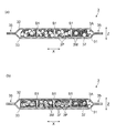
- FIG. 1 shows an embodiment of the heating tool of the present invention.
- the warming tool 1 shown in the figure is of a so-called eye mask type, and is used to bring the water vapor heated to a predetermined temperature into contact with the eyes of a human so as to cover the eyes and heat the eyes and its surroundings. Is used.
- the heat generating layer 31 does not include a fiber material.
- the mixture 3M can generate heat due to the oxidation reaction with oxygen.
- the heat generating layer 31 may exist only on the base material sheet 37, or even if the heat generating layer 31 exists on the base material sheet and the lower part of the heat generating layer 31 is buried in the base material sheet 37. Good.
- the heat generating main body 3A shown in FIG. 4A is formed of a heat generating layer 31 and a base material sheet 37. If necessary, as shown in FIG. 4B, the heat-generating main body 3A has the same or different material or composition as the base sheet 37 on the surface side of the heat generating layer 31 on which the base sheet 37 is not arranged.
- the second base material sheet 38 formed in step 1 may be further arranged. Instead of or in addition to this, a water-absorbing sheet or the like containing a water-absorbing material described later may be further arranged.
- a form that is movable in the body (hereinafter, this form is also referred to as "powder type"), or (iii) a form in which the mixture 3M itself is formed into a sheet shape (hereinafter, this form is also referred to as "sheet type”). I say.) etc. That is, the heating element manufactured by the above-mentioned coating method is classified into the “coating type”, and the heating element manufactured by the paper-making method is classified into the "sheet type”.
- the form of the slits S1 is not limited to this, and some or all of the slits S1 may be formed by notches that penetrate the heating layer 31 in the thickness direction Z and do not penetrate the base material sheet 37 in the thickness direction Z. ..
- the respective forms of the slit S1 described above may be present in combination.
- the particles of the oxidizable metal contained in the heat generating layer 31 include particles of iron, aluminum, zinc, manganese, magnesium, calcium and the like.
- the particle size of the particles of the oxidizable metal can be, for example, about 0.1 ⁇ m or more and 300 ⁇ m or less.
- the electrolyte an electrolyte capable of dissolving the oxide formed on the surface of the particles of the oxidizable metal is used. Examples thereof include alkali metal, alkaline earth metal or transition metal sulfates, carbonates, chlorides or hydroxides.
- the base sheet 37 has a basis weight of preferably 10 g/m 2 or more, more preferably 35 g/m 2 or more, and preferably 200 g/m 2 or less, from the viewpoint of ensuring sufficient sheet strength. It is preferably 150 g/m 2 or less.
- the basis weight of the oxidizable metal in the heat generating layer 31 is preferably 100 g/m 2 or more, more preferably 200 g/m 2 or more, and preferably 3000 g/m 2 from the viewpoint of ensuring a sufficient heat generation amount. Or less, more preferably 1500 g/m 2 or less.
- its basis weight is preferably in the same range as the base material sheet 37.
- a plurality of linear slits S1 are formed, and one row of first slit rows in which the slits S1 are arranged to extend in one direction A form in which L1 is formed, or a form in which a plurality of linear slits S1 are formed as shown in FIG. 6C, and these slits are arranged in parallel in the same direction, etc.
- the slit S1 formed of an arcuate cut for example, a form in which one arcuate slit S1 is formed as shown in FIG. 6D, or an arcuate form as shown in FIG. 6E.
- a plurality of slits S1 are formed and these slits S1 are present so as to be located on the same circumference, or as shown in FIG. 6(f), a plurality of arcuate slits S1 are formed, In addition, there may be mentioned a form in which these slits S1 are present so as to be positioned in two or more concentric circles.
- the symbol CF indicates the circumference of the virtual circle
- the symbol CC indicates the center of the virtual circle.
- the interval W3 between the first slit rows L1 is preferably 4 mm or more, and more preferably 8 mm. Above, it is preferably 25 mm or less, more preferably 15 mm or less.
- the interval W3 between the first slit rows L1 may be the same or different.
- the number of rows of the first slit row L1 is preferably 1 row or more, more preferably 2 rows or more, and further preferably 3 rows or more. Also, it is preferably 10 rows or less, more preferably 5 rows or less.
- the sheet material that can be used for the heating element 3, the ear hook 4, the first sheet 5, and the second sheet 6 has breathability, moisture permeability, texture, stretchability, strength, and composition of the heating sheet and the heating composition. It may be appropriately determined in consideration of properties such as leakage prevention of the material, and for example, non-woven fabric, woven fabric, paper, resin film, or a combination thereof is used. Examples of the sheet material having high air permeability and preventing leakage of a heat generating sheet and the like include melt blown nonwoven fabric, paper and moisture permeable film, and these are used alone or in combination, and the skin side sheet 32 and the non-skin side sheet 33 are used. , And each of the base material sheets 37 and 38.
- the air permeability of the first sheet 5 is preferably lower than that of the second sheet 6.
- the air permeability of the first sheet 5 is preferably 0.01 seconds/100 mL or more, more preferably 50 seconds/100 mL or more, and further preferably 2000 seconds/100 mL or more. Further, it is preferably 15000 seconds/100 mL or less, more preferably 10000 seconds/100 mL or less.
- the air permeability of the second sheet 6 is preferably as high as possible, specifically, 50 seconds/100 mL or more is preferable, 4000 seconds/100 mL or more is more preferable, and 20000 seconds/100 mL or more.
- the basis weight of the second sheet 6 is preferably larger than the basis weight of the first sheet 5.
- the basis weight of the first sheet 5 is preferably 10 g/m 2 or more, more preferably 20 g/m 2 or more, and preferably 200 g/m 2 or less and 130 g/m 2 or less. Is more preferable.
- the basis weight of the second sheet 6 is preferably 10 g/m 2 or more, more preferably 30 g/m 2 or more, and preferably 200 g/m 2 or less, 150 g/m 2. It is more preferably 2 or less.
- the skin-side sheet 32 and the non-skin-side sheet 33 can have the same basis weight as the first sheet 5 and the second sheet 6.
- the heating tool of the present invention having the above-described configuration, since the first slit S1 is formed in the heat generating layer 31 and at least one of the base material sheets 37 and 38, the oxidizable metal Even when the heat generating layer 31 is hardened due to oxidation, the flexibility of the heat generating main body 3A can be maintained, and as a result, the fit to the eyes is improved. Further, since the first slit S1 is formed in the heat generating layer 31 and at least one of the base material sheets 37 and 38, the oxidation reaction caused by the contact between the heat generating layer 31 and oxygen in the air. Since it is easy to proceed, the time until heat is generated to a desired temperature can be shortened, and as a result, the heat generation characteristics such as the rising speed of heat generation when the heating tool is used are excellent.
- the heat-generating body 3A by providing the heat-generating body 3A with a slit S1 formed by a notch penetrating in the thickness direction Z, flexibility of the heat-generating body 3A is increased, and oxygen supply to the heat-generating layer 31 is increased. Can be performed more effectively, and the eye fit and the heat generation characteristics when the heating tool is used are further improved.
- the first slit row L1 in which the plurality of slits S1 are intermittently arranged is formed, the heat-generating main body 3A is not completely divided into individual parts, and the storage state (not There is also an advantage that the deterioration of the heating element in the usage state) is reduced.
- the heat generating main body 3A includes the first slit row as shown in FIGS. 7(a) to (d).
- L1 it is preferable to have a second slit row L2 formed so as to extend in a direction intersecting with the slit row L1.
- the second slit row L2 shown in FIGS. 7A to 7D is, like the first slit row L1, a plurality of linear second slits that are not penetrated or penetrated in the thickness direction.
- the groups of S2 are arranged intermittently so as to extend along the lateral direction X.
- the first slit row L1 is adjacent to the front and rear sides. It is even more preferable that the first slit S1 and the second slit S2 are arranged so that the second slit S2 in the second slit row L2 does not pass between the two first slits S1. ..
- the pitch of the slits in the adjacent slit rows is the same, and the length of one slit is shorter than the length of the other slit.
- FIG. 7B the pitch of the slits in the adjacent slit rows is the same, and the length of one slit is shorter than the length of the other slit.
- the phase of one slit may be different between adjacent slit rows, or as shown in FIG. 7(d), the pitch of slits in adjacent slit rows may be the same. It can be formed by making the length of one slit longer than the length of the other slit.
- the slit form shown in FIG. 7(b) is more preferable, and the slit form shown in FIG. 7(a) or (c) is further preferable, and FIG. It is more preferable that the slit shape shown in FIG.
- the number of rows of the second slit row L2 is preferably 1 row or more, more preferably 2 rows or more, and further preferably 4 rows or more, from the viewpoint of improving the fitting property of the heating tool and the heat generation characteristics. Further, it is preferably 7 columns or less, more preferably 5 columns or less.
- the heat generating layer 31 in the heat generating element 3 further includes the fiber material 3F. That is, the heat generation layer 31 is preferably a mixture containing the fiber material 3F in addition to the particles of the oxidizable metal, the electrolyte, the carbon material, and water. Since the heat generating layer 31 contains the fiber material 3F, the water retaining property, the moldability, and the shape retaining property of the heat generating element 3 are improved.
- the heating tool having a high rising rate of heat generation and excellent heat generating characteristics.
- the heat generating layer 31 shown in FIGS. 8A and 8B may be in the form of a powder type or a sheet type.
- the heating element 3 in the present invention in the sheet-type embodiment, the heating element 31 is formed into a sheet by paper-making with a mixture containing the fiber material 3F dispersed therein (hereinafter, this embodiment will be referred to as " (Also referred to as "papermaking type"), the heating device of the present invention has improved heat generation characteristics to the same level as a heating device having a coating type heating layer 31 and improved fitability. Becomes
- the heat generating main body 3A shown in FIGS. 8A and 8B includes at least a heat generating layer 31 and a base material sheet 37, and the heat generating layer 31 is provided on one surface of the base material sheet 37.
- the heat generating main body 3A shown in FIG. 8A is formed of a heat generating layer 31 and a base material sheet 37. If necessary, as shown in FIG. 8B, the heat-generating main body 3A has the same or different material or composition as the base sheet 37 on the surface side of the heat generating layer 31 on which the base sheet 37 is not arranged.
- the second base material sheet 38 formed in step 1 may be further arranged. Instead of or in addition to this, a water-absorbing sheet or the like containing a water-absorbing material described later may be further arranged.
- the slit S1 in the present embodiment is formed so as to penetrate the heat generating layer 31 and each of the base material sheets 37 and 38 in the thickness direction Z, it may be a slit that does not penetrate in the thickness direction Z instead.
- the exothermic body 3A shown in FIG. 8A is formed of the exothermic layer 31 and the base sheet 37 as described above.
- a plurality of slits S1 each having a notch formed by the heat-generating layer 31 and the base material sheet 37 penetrating in the thickness direction Z are formed.
- the formation positions of the slits S1 between the heat-generating layer 31 and the base material sheet 37 are the same. That is, the slit S1 is formed at the same position on both the heat generating layer 31 and the base material sheet 37 in the plan view of the heat generating main body 3A.
- the form of the slits S1 is not limited to this, and some or all of the slits S1 may be formed by notches that penetrate the heating layer 31 in the thickness direction Z and do not penetrate the base material sheet 37 in the thickness direction Z. ..
- the respective forms of the slit S1 described above may be present in combination.
- a plurality of slits S1 are formed which are notches through which the heat-generating layer 31 and each of the base material sheets 37 and 38 penetrate in the thickness direction Z.
- the formation positions of the slits S1 of the heat generating layer 31 and the respective base material sheets 37, 38 are the same. That is, the slit S1 is formed at the same position on all of the heat generating layer 31 and each of the base material sheets 37 and 38 in the plan view of the heat generating main body 3A.
- the form of the slit S1 is not limited to this.
- the slits S1 penetrate one of the two base material sheets 37, 38 in the thickness direction Z, and the heating layer 31 in the thickness direction.
- One of the base material sheets 37, 38 is formed by a notch that does not penetrate the Z, and the other of the base material sheets 37, 38 has no notch
- all the slits S1 penetrate one of the base material sheets 37 and 38 and the heat generating layer 31 in the thickness direction Z, and the other of the base material sheets 37 and 38 does not penetrate in the thickness direction Z.
- a form in which a notch is formed or a combination of the forms of the slit S1 described above can be mentioned.
- Natural fiber materials include plant fibers (cotton, cabbage, wood pulp, non-wood pulp, peanut protein fiber, corn protein fiber, soy protein fiber, mannan fiber, rubber fiber, hemp, Manila hemp, sisal hemp, New Zealand hemp, Rafu hemp. , Palm, igusa, straw, etc.), animal fiber (wool, goat, mohair, cashmere, alcapa, angora, camel, vicuna, silk, feather, down, feather, algin fiber, chitin fiber, gazein fiber, etc.), mineral fiber (Asbestos and the like).
- plant fibers cotton, cabbage, wood pulp, non-wood pulp, peanut protein fiber, corn protein fiber, soy protein fiber, mannan fiber, rubber fiber, hemp, Manila hemp, sisal hemp, New Zealand hemp, Rafu hemp. , Palm, igusa, straw, etc.
- animal fiber wool, goat, mohair, cashmere, alcapa, angora, camel, vicuna, silk, feather
- synthetic fiber materials include semi-synthetic fibers (acetate, triacetate, acetate acetate, promix, chlorinated rubber, chlorinated rubber, etc.), synthetic polymer fibers (nylon, aramid, polyvinyl alcohol, polyvinyl chloride, polyvinylidene chloride, Polyester such as polyethylene terephthalate, polyacrylonitrile, acrylic, polyethylene, polyethylene, polypropylene, polystyrene, polyurethane, rayon, viscose rayon, cupra, etc.), metal fiber, carbon fiber, glass fiber and the like. These fiber materials can be used alone or in combination. Among these, the fiber material uses at least one of wood pulp, cotton, and polyester, from the viewpoint of achieving both uniform dispersibility with the oxidizable metal and oxygen permeability by ensuring voids, and enhancing heat generation characteristics. It is preferable.
- the fiber material When the mixture forming the heat generating layer 31 contains the fiber material 3F, the fiber material has an average fiber length of preferably 0.5 mm or more, more preferably 2 mm or more, and preferably 10 mm or less, more preferably 5 mm or less. is there. When the fiber length of the fiber material is within such a range, the thickness of the heat generating layer 31 can be kept uniform, and the heat generating element 3 having excellent heat generating characteristics can be manufactured.
- the content of the fiber material 3F contained in the mixture forming the heat generating layer 31 is preferably 5% by mass or more, more preferably 10% by mass or more, and preferably 50% by mass or less, more preferably 35% by mass or less. is there. When the content of the fiber material is in such a range, the heating element 3 having excellent heat generation characteristics can be manufactured.
- FIGS. 10A and 10B are cross-sectional views showing still another embodiment of the heating element 3.
- the embodiment of the heating element 3 including the fiber material used in the present invention include the modes shown in FIGS. 9B and 10B.
- the heat generating layer 31 in the heat generating element 3 further contains the water absorbing material 3P. That is, the heat generating layer 31 is preferably a mixture containing the water-absorbing material 3P in addition to the particles of the oxidizable metal, the electrolyte, the carbon material, and water.
- the water absorbing material 3P in the heat generating layer 31 can be appropriately controlled, and as a result, the heat generating characteristics of the heating tool 1 can be successfully controlled.
- the heat generating main body 3A shown in FIGS. 9(a) and 9(b) and FIGS. 10(a) and 10(b) includes at least the heat generating layer 31 and the base sheet 37, as in the above-described embodiment.
- the heat generating layer 31 is provided on one surface of the base material sheet 37.
- the heat-generating main body 3A shown in FIGS. 9A and 9B is composed of a heat-generating layer 31 and a base sheet 37. If necessary, as shown in FIGS. 10(a) and 10(b), the heat-generating main body 3A is the same as the base material sheet 37 on the surface side of the heat generating layer 31 on which the base material sheet 37 is not arranged. Or a second base material sheet 38 formed of a different material or composition may be further arranged. Instead of or in addition to this, a water absorbing sheet or the like containing the water absorbing material 3P may be further arranged.
- the slit S1 in the present embodiment is formed so as to penetrate the heat generating layer 31 and each of the base material sheets 37 and 38 in the thickness direction Z, it may be a slit that does not penetrate in the thickness direction Z instead.
- the exothermic body 3A shown in FIGS. 9A and 9B is formed of the exothermic layer 31 and the base sheet 37 as described above.
- a plurality of slits S1 each having a notch formed by the heat-generating layer 31 and the base material sheet 37 penetrating in the thickness direction Z are formed.
- a plurality of slits S1 formed by notches through which the heat-generating layer 31 and each of the base material sheets 37 and 38 penetrate in the thickness direction Z are formed.
- the formation positions of the slits S1 of the heat generating layer 31 and the respective base material sheets 37, 38 are the same. That is, the slit S1 is formed at the same position on all of the heat generating layer 31 and each of the base material sheets 37 and 38 in the plan view of the heat generating main body 3A.
- the form of the slit S1 is not limited to this.
- some or all of the slits S1 penetrate one of the two base material sheets 37, 38 in the thickness direction Z, and the heating layer 31 in the thickness direction.
- One of the base material sheets 37, 38 is formed by a notch that does not penetrate the Z, and the other of the base material sheets 37, 38 has no notch
- all the slits S1 penetrate one of the base material sheets 37 and 38 and the heat generating layer 31 in the thickness direction Z, and the other of the base material sheets 37 and 38 does not penetrate in the thickness direction Z.
- a form in which a notch is formed or a combination of the forms of the slit S1 described above can be mentioned.
- the second slit S2 in addition to the first slit S1, the second slit S2, like the slit S1 described above, penetrates, does not penetrate, or these. Can be in the form of a combination.
- the heating layer 31 includes particles of an oxidizable metal, an electrolyte, a carbon material, water and a water absorbing material 3P, and Alternatively, the heating layer 31 may be a mixture containing the water absorbing material 3P as in the embodiment of the present invention shown in FIGS. 9B and 10B.
- the aspect may further include the above-mentioned fiber material. Specific embodiments of these are, for example, (i) a sheet-shaped heat generating layer 31 in which a water absorbing material and, if necessary, a fiber material are uniformly mixed, or (ii) the water absorbing material is a heat generating layer 31.
- the sheet-like heat-generating layer 31 having a structure in which the water-absorbing material is mainly present in the central region of the thickness direction of the heat-generating layer 31 and the surface of the heat-generating layer 31 is substantially absent, or (iii) the water-absorbing material generates heat.
- An example is a sheet-shaped heat generating layer 31 that is mainly present on one surface side of the layer 31.
- the basis weight of the water-absorbent material 3P is preferably 20 g/m 2 or more, more preferably 40 g/m 2 or more, preferably 100 g/m 2 or less, and more preferably 80 g/m from the viewpoint of improving heat generation durability. 2 or less, more preferably 70 g/m 2 or less.
- This basis weight is a value when the heat generating layer 31 is formed on one surface of the base material sheet 37.
- FIGS. 12A and 12B are sectional views showing still another embodiment of the heating element 3.
- the heat-generating main body 3A is further provided with a water-absorbing material layer 3L containing a water-absorbing material 3P on the side opposite to the base material sheet 37 with the heat-generating layer 31 interposed therebetween.
- the water absorbing material layer 3L shown in the figure is arranged so as to be in contact with the heat generating layer 31. Even with such a configuration, the water content of the heating layer 31 can be appropriately controlled, and as a result, the heating characteristics of the heating tool 1 can be successfully controlled.
- Examples of the form of the water absorbing material layer 3L include (i) spraying the water absorbing material 3P on the heat generating layer 31 or (ii) including the water absorbing material 3P on the surface side of the heat generating layer 31 on which the base sheet 37 is not arranged. A water absorbing sheet is placed on top of another, or (iii) a water absorbing material 3P is sprinkled or the water absorbing sheet is placed on the surface side of the heat generating layer 31 on which the base material sheet 37 is not placed, and the heat generating layer of the water absorbing material 3P is further arranged.
- the second base material sheet 38 may be superposed on the surface on the side where 31 is not arranged.
- the water-absorbent material layer 3L can be formed by spraying the water-absorbent material 3P or arranging a sheet-shaped material containing the water-absorbent material 3P.
- the material, shape and basis weight of the water absorbent material 3P can be the same as described above.
- the heat generating main body 3A shown in FIGS. 11(a) and (b) and FIGS. 12(a) and 12(b) includes at least the heat generating layer 31 and the base sheet 37, as in the above-described embodiment.
- the heat generating layer 31 is provided on one surface of the base material sheet 37.
- Examples of the embodiment of the heating element 3 including the fiber material used in the present invention include the modes shown in FIGS. 11B and 12B.
- the heat generating main body 3A shown in FIGS. 11A and 11B is formed by disposing a water absorbing material layer 3L containing a water absorbing material 3P in addition to the heat generating layer 31 and the base material sheet 37. If necessary, as shown in FIGS.
- the heat-generating main body 3A is the same as the base sheet 37 on the surface side of the water-absorbing material layer 3L on which the heat-generating layer 31 is not arranged.
- a second base material sheet 38 formed of a different material or composition may be further arranged.
- the slit S1 in the present embodiment is formed so as to penetrate the heat generating layer 31 and each of the base material sheets 37 and 38 in the thickness direction Z, it may be a slit that does not penetrate in the thickness direction Z instead.
- the heat-generating main body 3A shown in FIGS. 11A and 11B is formed to include the water absorbing material layer 3L in addition to the heat generating layer 31 and the base material sheet 37.
- the exothermic body 3A shown in the figure is provided with a plurality of slits S1 each formed by a notch through which the exothermic layer 31, the base sheet 37, and the water absorbing material layer 3L penetrate in the thickness direction Z.
- the heat-generating layer 31 and the base sheet 37 are formed at the same position of the slit S1.
- the form of the slit S1 is not limited to this, and a part or all of the slit S1 is formed by a notch that penetrates the heat generating layer 31 and the water absorbing material layer 3L in the thickness direction Z and does not penetrate the base material sheet 37 in the thickness direction Z. It may have been done.
- the respective forms of the slit S1 described above may be present in combination.
- the heat generating main body 3A shown in FIGS. 12(a) and 12(b) has a slit formed by a notch in which all of the heat generating layer 31, each of the base material sheets 37 and 38, and the water absorbing material layer 3L penetrate in the thickness direction Z.
- a plurality of S1s are formed.
- the heat-generating layer 31, each of the base material sheets 37, 38, and the slit S1 of the water-absorbing material layer 3L are formed at the same position and at the same position. ..
- the form of the slit S1 is not limited to this.
- the slits S1 penetrate one of the two base material sheets 37, 38 in the thickness direction Z, and the heating layer 31 in the thickness direction.
- the base sheet 37, 38 is formed of a notch that does not penetrate the Z, and the other of the both base sheet 37, 38 has no notch.
- One of the base material sheets 37 and 38 is formed with a notch that penetrates one of the base material sheets 37 and 38 in the thickness direction Z and penetrates the heat generating layer 31 and the water absorbing material layer 3L in the thickness direction Z.
- the slits S1 penetrate the heat generating layer 31 and the water absorbing material layer 3L in the thickness direction Z by one of the both base material sheets 37, 38, and both base material sheets 37, 38
- the other of 38 includes a form in which a notch that does not penetrate in the thickness direction Z is formed, or a combination of the forms of the slit S1 described above.
- the second slit S2 in the case where the second slit S2 is formed in addition to the first slit S1, the second slit S2, like the slit S1 described above, penetrates, does not penetrate, or these. Can be in the form of a combination.
- the heating tool 1 As a method for manufacturing the heating tool 1, (i) a coating material containing particles of an oxidizable metal, a carbon component, and water is applied to one surface of a base material sheet 37 to form a heat generating layer 31, and then heat is generated.
- a method of forming slits in the layer 31 and the base material sheet 37 (hereinafter, this manufacturing method is also referred to as "coating type manufacturing method"), or (ii) particles of an oxidizable metal, carbon component, water and fiber material
- the composition containing is paper-made to form an intermediate molded body, the intermediate molded body is made to contain an electrolyte to form a heat generating layer 31, and then the heat generating layer 31 and the base material sheet 37 are laminated to form a slit.
- this manufacturing method is also referred to as a “papermaking mold manufacturing method”). Whichever manufacturing method is used, it is possible to manufacture a warming tool having high fitting properties and excellent heat generation characteristics.
- the coating type manufacturing method in the heating tool 1 includes a step A of coating an electrolyte on one surface of the base material sheet 37 in a solid state or an aqueous solution state, and particles of an oxidizable metal not containing the electrolyte.
- a heating layer forming step including a step B of applying a coating material containing a carbon material and water.
- the step of applying the electrolyte can be carried out by a means such as spraying the electrolyte in a solid state or spraying an aqueous solution.
- the step of applying the coating material containing particles of the oxidizable metal, the carbon material and water can be performed by applying the coating material using a coating device such as a die coater.
- step A or step B may be performed first, or step A and step B may be performed simultaneously.
- the heat generating layer 31 containing the particles of the oxidizable metal, the electrolyte, the carbon material, and water is formed on one surface of the base material sheet 37.
- the heat generating layer 31 contains a fibrous material
- the base material sheet 37 is coated with a coating material mixed with the fibrous material, or the fibrous material is sprinkled on the heat generating layer 31, so that the particles of the oxidizable metal and the electrolyte are A heat generating layer 31 containing carbon material, fiber material and water is formed.
- a second base material sheet 38 may be further laminated on the opposite side of the base material sheet 37 with the heat generating layer 31 interposed therebetween, if necessary.
- the heating element 3 including the water-absorbing material 3P is formed, after the heating layer 31 is formed through the heating layer forming step, before the formation thereof, or between the steps A and B in the heating layer forming step.
- a water-absorbing material supplying step of supplying the water-absorbing material 3P to the surface of the base material sheet 37 on which the heat-generating layer 31 is formed (or the surface where the heat-generating layer is to be formed) may be provided simultaneously with the formation of the heat-generating layer 31.
- the water-absorbing material 3P is supplied by mixing the water-absorbing material 3P with the coating material, applying the water-absorbing material 3P on the coating material, or laminating a water-absorbing sheet containing the water-absorbing material 3P on the coating material. It can be carried out.
- a second base material sheet 38 may be further laminated on the opposite side of the base material sheet 37 with the heat generating layer 31 interposed therebetween, if necessary.
- a slit consisting of a linear or arcuate cut is formed in the heat generating layer 31 and the base material sheet 37 (slit forming step).
- a slit formed of a linear cut for example, one or more first slit rows L1 arranged so that a group of one or a plurality of first slits S1 extends in one direction is formed in one row or in a plurality of rows.
- a second slit in which a group of one or a plurality of second slits S2 extending in a direction intersecting the extending direction of the first slit row L1 is arranged so as to extend in one direction.
- the row L2 may be formed in one row or a plurality of rows to form the heat generating main body 3A.
- Each of the slits S1 and S2 of the first slit row L1 and the second slit row L2 is formed by using a cutting blade and causing the cutting blade to enter the heat generating main body 3A including the heat generating layer 31 and the base sheet 37. ..
- Each slit S1, S2 can be a slit that penetrates or does not penetrate in the thickness direction Z by appropriately adjusting the degree of penetration of the cutting blade.
- the first row is formed so as to extend in the same direction as the conveying direction.
- One or a plurality of slit rows L1 are formed.
- first slit row L1 for example, a first cutter roll having intermittently extending cutting edges along the circumferential direction of the roll and having cutting blades arranged in one or more rows in the axial direction of the roll can be used. ..
- second slit row L2 a second cutter roll that intermittently extends along the axial direction of the roll and that has cutting blades arranged in one or more rows in the circumferential direction of the roll may be used. ..
- first slit row L1 is formed by using the first cutter roll without using the second cutter roll for forming the second slit row L2. do it.
- both the slit rows L1 and L2 are formed in a direction that intersects the transport direction, for example, while the substrate sheet 37 on which the heat generating layer 31 is formed is transported in one direction, the cutting blade is set in the extending direction. It may be formed by using a cutter roll arranged so as to intersect the axial direction of the roll. In addition, when forming the first slit formed of a notch on an arc as shown in FIGS. 6D to 6F, for example, the base sheet 37 on which the heat generating layer 31 is formed is arranged in one direction. It may be formed by using a cutter roll having an arcuate cutting blade arranged on a peripheral surface of the roll at a predetermined position while being conveyed.
- the coating-type manufacturing method in order to form each of the slits S1 and S2 in the heat generating layer 31, it is preferable to reduce the fluidity of the coating so that it is difficult to restore the state before the cutting blade enters. ..
- the fluidity of the paint can be lowered by, for example, adding a thickener to the paint or reducing the water content of the paint.
- the content of the thickener contained in the coating material for forming the heat generating layer 31 is 100% from the viewpoint that the fitting property of the heating tool is improved, the heat generation characteristic is improved, and the processability is combined at a high level. It is preferably 0.05 parts by mass or more, more preferably 0.1 parts by mass or more, and preferably 10 parts by mass or less, more preferably 5 parts by mass or less, based on parts by mass.
- the content of water is preferably 15% by mass or more, and more preferably 25% by mass or more based on the total mass of the coating material from the viewpoint of simultaneously improving the exothermic characteristics of the heating device and the processability. Further, it is preferably 60% by mass or less, more preferably 45% by mass or less.
- the fluidity of the coating material is preferably 2000 mPa ⁇ s or more, more preferably 5000 mPa ⁇ s or more, and preferably 30,000 mPa ⁇ s or less, more preferably 15000 mPas as the viscosity of the coating material. ⁇ S or less.
- the viscosity was measured at 23° C. and 50% RH by using a No. 4 rotor of B-type viscometer and rotating the rotor at 6 rpm.
- the coating amount of the paint is preferably 180 g/m 2 or more, more preferably 350 g/m 2 or more, and preferably 1200 g/m 2 or less, more preferably 1000 g/m 2 or less, and further as a basis weight. It is preferably 800 g/m 2 or less. Even when the fibrous material and the water absorbing material are mixed with the coating material, the coating amount may be within the above range. With such a coating amount, it is possible to easily form the slits in the heat generating layer 31 and the base material sheet 37, and as a result, it is possible to obtain the warming tool 1 having high fitting properties and heat generating characteristics. If the content of the water absorbing material is the above-mentioned basis weight, the effect of the present invention is sufficiently exhibited.
- the heat-generating main body 3A in which the slits are formed is housed in a bag body composed of the skin side sheet 32 and the non-skin side sheet 33 to form the heat generating body 3.
- the heat generating body 3 is placed on the skin side.
- the sheet 32 and the first sheet 5 are held between the first sheet 5 and the second sheet 6 such that the non-skin side sheet 33 and the second sheet 6 face each other. In this way, the desired heating tool 1 can be manufactured.
- a composition containing particles of an oxidizable metal, a carbon material, a fiber material and water is manufactured.
- the content of the oxidizable metal particles in the composition excluding water is preferably 10% by mass or more, more preferably 30% by mass or more, from the viewpoint of enhancing flexibility and heat generation characteristics of the heat generating layer 31. , Preferably 90 mass% or less, more preferably 80 mass% or less.
- the content of the carbon material in the composition excluding water is preferably 1.5% by mass or more, more preferably 3% by mass or more, and preferably 15% by mass or less, more preferably It is 10 mass% or less.
- the content of the fiber material in the composition excluding water is preferably 2% by mass or more, more preferably 5% by mass or more, and , Preferably 80 mass% or less, more preferably 50 mass% or less.
- the water absorbing material 3P When the water absorbing material 3P is dispersed in the heat generating layer 31, the water absorbing material 3P can be contained in the composition.
- the content of the water-absorbing material 3P in the composition excluding water is preferably 1% by mass or more, more preferably 3% by mass or more, and preferably 15% by mass or less, more preferably 10% by mass or less. ..
- the composition may be further added with additives usually used in the papermaking of paper, such as colorants, paper strength enhancers, retention aids, fillers, thickeners, pH adjusters, bulking agents and the like. Good.
- additives usually used in the papermaking of paper such as colorants, paper strength enhancers, retention aids, fillers, thickeners, pH adjusters, bulking agents and the like. Good.
- the blending amount of the additive in the raw material composition can be appropriately set according to the additive to be added.
- the composition is paper-made to form an intermediate molded body having a predetermined shape.
- a conventional method used for papermaking of a molded body of various forms such as a sheet shape and a three-dimensional shape can be used without particular limitation.
- a papermaking method for example, in the case where the intermediate molded body is formed into a sheet, a cylinder paper machine, a fourdrinier paper machine, a fourdrinier paper machine, a twin wire paper machine, or the like, which is a continuous paper machine, is used.
- Examples of the method include a papermaking method and a handmade method that is a batch-type papermaking method.
- the intermediate molded body has a three-dimensional shape, for example, it is described in Japanese Patent No. 3155522, Japanese Patent No. 3155503, and Japanese Patent No. 3072088.
- the method can be appropriately adopted. From the viewpoint of forming the thin heating element 3, it is preferable to make a sheet-shaped intermediate molded body. In this step, the fibrous material can be further kneaded with the surface of the molded product, if necessary.
- the sheet-shaped intermediate molded body obtained by papermaking has a water content of preferably 70% by mass or less, more preferably 60% by mass or less, and its lower limit is preferably from the viewpoint of maintaining moldability and mechanical strength. You may have the dehydration process of dehydrating until it becomes 5 mass% or more, More preferably, it becomes 10 mass% or more.
- Examples of the dehydration method include dehydration by suction, a method of dehydrating by blowing heated air, a method of applying pressure with a pressure roll or a pressure plate for dehydration. These dehydrations may be performed in an air atmosphere, or preferably in an inert gas atmosphere from the viewpoint of suppressing the oxidation of the oxidizable metal. In this way, a sheet-shaped and dry intermediate molded body containing the particles of the oxidizable metal, the carbon material and the fiber material, and further containing the water absorbing material as necessary is formed.
- the intermediate molded body is made to contain an electrolyte to form the heat generating layer 31.
- the step of containing the electrolyte is preferably performed in an atmosphere of an inert gas such as nitrogen or argon.
- an appropriate method can be adopted depending on the method of treating the intermediate molded body after papermaking, the water content, the form and the like.
- an aqueous solution of the electrolyte can be impregnated into the intermediate molded body by a method such as spraying, dipping, or gravure coating, or a solid electrolyte can be dispersed in the intermediate molded body.
- the sheet-shaped heat generating layer 31 formed in this manner can be laminated, for example, and disposed on one surface of the base material sheet 37. If necessary, the second base material sheet 38 can be laminated on the surface of the heat generating layer 31 on the side where the base material sheet 37 is not arranged.
- a slit formed by a linear or arcuate cut is formed in the heat generating layer 31 and the base material sheet 37.
- a slit formed of a linear cut for example, one or more first slit rows L1 arranged so that a group of one or a plurality of first slits S1 extends in one direction is formed in one row or in a plurality of rows.
- a second slit row L2 in which a group of one or a plurality of second slits S2 extending in a direction intersecting with the extending direction of the first slit row L1 is arranged so as to extend in one direction.
- the method of forming the slit row can be performed in the same manner as the above-described coating type manufacturing method.
- the composition does not contain a water-absorbing material and the heating element 3 contains a water-absorbing material, before or after forming the slit row, on the surface side of the heating layer 31 where the base sheet 37 is not arranged.
- the heat absorbing body 3A having the water absorbing material layer 3L containing the water absorbing material 3P can be formed by spraying the water absorbing material 3P or disposing the water absorbing sheet containing the water absorbing material 3P. After that, the second base material sheet 38 may be superposed on the surface side of the water absorbing material layer 3L where the heat generating layer 31 is not arranged, if necessary.
- the basis weight of the water absorbent material 3P in this step can be the same as the basis weight described above.
- the heat-generating main body 3A in which the slits are formed is housed in a bag body composed of the skin side sheet 32 and the non-skin side sheet 33 to form the heat generating body 3.
- the heat generating body 3 is placed on the skin side.
- the sheet 32 and the first sheet 5 are held between the first sheet 5 and the second sheet 6 such that the non-skin side sheet 33 and the second sheet 6 face each other. In this way, the desired heating tool 1 can be manufactured.
- the present invention has been described above based on its preferred embodiments, the present invention is not limited to the above embodiments.
- the form of the ear hook 4 in the heating tool 1 is not limited to the sheet-like member shown in FIGS. 1 and 2 as long as the main body 2 can be fixed to both eyes of the user.
- a string-shaped ear hooking portion 4 may be adopted, or a thread-shaped or band-shaped ear hooking portion 4 may be adopted.
- the elastic body such as rubber to make the ear hook 4 which is expandable and contractible.
- the form of the heating element 3 in the above-described heating tool 1 is described as a configuration in which the two heating elements 3 are held separately, if the two eyes of the user and their surroundings can be given a warm feeling, the heating element 3 is heated.
- the form of the ingredient is not particularly limited.
- one heating element having a shape and a size capable of covering both eyes of the user and its surroundings may be held between the first sheet 5 and the second sheet 6, and three or more heat generating elements may be generated.
- the body may be held between the first sheet 5 and the second sheet 6.
- the heat-generating main body 3A has been described as a form in which the base material sheet 37 and the second base material sheet 38 are arranged as necessary, but instead of this, a papermaking type heat generation.
- the base material sheets 37 and 38 may not be arranged. That is, only the sheet-shaped heat generating layer 31 having the above-described slits is housed in the flat packaging material having the skin side sheet 32 on one side and the non-skin side sheet 33 on the other side, and the heating element 3 May be. Even in this case, the heat generating layer 31 can obtain good effects such as water retention, moldability and shape retention.
- the paper-making type sheet-shaped heat generating layer 31 is formed with the slits of the above-described aspects, it is possible to improve heat generation characteristics to a level equivalent to that of the heating tool including the coating type heating element 3 and to generate the heat.
- the warming tool including the body 3 has improved fit to the wearer.
- the interval W3 between the first slit rows L1 is shown in FIG.
- the gap W6 is larger than the gap W6 between the second slit rows L2 or smaller than the gap W6 as shown in FIG. 14B, and the gap W3 is the gap W6. It is more preferable that the size is smaller than the above. With such a configuration, in addition to the improvement in heat generation characteristics, the fitting property of the heating tool is further improved. This is particularly advantageous when the above-mentioned slits S1 and S2 are formed in the paper-making type heat generating layer 31.
- the pitches of the first slit rows L1 formed in the adjacent first slit rows L1 are the same and the phases are shifted by a half pitch, and each slit S1 is staggered. It has a childlike form.
- the pitches of adjacent slit rows L1 may be the same or different.
- the phase shift between the adjacent slit rows L1 may be periodic or aperiodic.
- the slit formation mode shown in FIG. 15 has been described by taking as an example the mode in which only the first slit S1 and the first slit row L1 are formed, but the present invention is not limited to this mode, and the second slit S2 and the second slit S2
- the slit row L2 may be further formed.
- a plurality of second slit rows L2 are formed, and when any two adjacent slit rows L2, L2 are viewed along the direction in which the slit rows extend, at any position, It is also preferable that at least one slit S2 forming the slit row L2 is present.
- the pitches of adjacent slit rows L2 may be the same or different.
- the phase shift between the adjacent slit rows L2 may be periodic or aperiodic.
- a heat generating layer is provided on one surface of the base sheet,
- the exothermic layer contains a mixture of oxidizable metal particles, an electrolyte, a carbon material and water,
- a heating tool in which one or more first slits each having a linear or arcuate cut are formed in the heat generating layer and the base sheet.
- ⁇ 2> The heating device according to ⁇ 1>, wherein the plurality of first slits formed by linear cuts are formed on the heat generating layer and the base sheet so as to be arranged in parallel in the same direction.
- ⁇ 3> The heating tool according to ⁇ 2>, wherein one second slit made of a notch is formed so as to extend in a direction intersecting with a direction in which the first slit extends.
- ⁇ 4> The heating device according to ⁇ 2>, wherein a plurality of second slits formed by notches are arranged in parallel in the same direction and extend in a direction intersecting with the extending direction of the first slits.
- ⁇ 5> The heating device according to ⁇ 4>, wherein the first slit and the second slit are arranged so that the first slit and the second slit do not intersect with each other.
- ⁇ 6> One or a plurality of first slit rows in which a group of a plurality of first slits formed of linear cuts are arranged to extend in one direction is formed, When a plurality of first slit rows are formed, the heating device according to ⁇ 1>, wherein the first slit rows are formed so as not to intersect with each other.
- the interval between the first slits in the first slit row is preferably 0.5 mm or more, more preferably 1 mm or more, and preferably 20 mm or less, more preferably 10 mm or less.
- the described heating equipment ⁇ 8>
- the number of rows of the first slit row is preferably 1 row or more, more preferably 2 rows or more, further preferably 3 rows or more, and preferably 10 rows or less, more preferably 5 rows or less, The heating tool according to any one of ⁇ 2>, ⁇ 6>, and ⁇ 7>.
- a plurality of first slits formed of linear cuts are formed, Any one of the above ⁇ 6> to ⁇ 8>, wherein one row of first slit rows in which a group of first slits are arranged to extend in one direction is formed in the heat generating layer and the base material sheet.
- a plurality of first slit rows are formed,
- the distance between the first slit rows is preferably 4 mm or more, more preferably 8 mm or more, and preferably 25 mm or less, more preferably 15 mm or less, according to the above ⁇ 2>, ⁇ 6> to ⁇ 8>.
- Heater according to any one of the above.
- a group of a plurality of second slits consisting of notches is formed in one row or a plurality of rows so that a second slit row arranged so as to extend in one direction extends in a direction intersecting with the first slit row, When a plurality of second slit rows are formed, the second slit rows are formed so as not to intersect with each other and extend in a direction intersecting with the first slit row, in ⁇ 6> above.
- the first slit and the second slit are arranged so that the first slit in the first slit row passes between two second slits adjacent to each other in the front and rear direction in the second slit row.
- ⁇ 14> The first slits and the second slits are arranged so that the second slits in the second slit row do not pass between the two first slits adjacent to each other in the front and rear direction in the first slit row.
- the length of the first slit is formed shorter than the length of the second slit, The first slit and the second slit are arranged so that the first slit S1 passes between the second slits S2 that are adjacent to each other in the second slit row direction.
- the above ⁇ 13> or ⁇ 13>14> The heating device described in 14>.
- ⁇ 16> The length of the first slit S1 and the length of the second slit S2 are the same, The first slit and the second slit are arranged such that the pitches of the first slit rows formed in the adjacent first slit rows are the same and the phases are shifted by a half pitch. > Or ⁇ 14>.
- the length of the first slit is formed longer than the length of the second slit,
- the first slit and the second slit are arranged so that the first slit passes between the second slits S2 adjacent to each other in the extending direction of the second slit row.
- the described heating equipment ⁇ 18> The heating tool according to any one of ⁇ 11> to ⁇ 17>, wherein the first slit row and the second slit row are orthogonal to each other.
- the heating device includes a main body having a lateral direction and a vertical direction orthogonal to the lateral direction, and having a shape elongated in the lateral direction,
- the main body includes the heat generating layer
- the first slit row and the second slit row are formed so as to intersect with both the horizontal direction and the vertical direction and be inclined so as not to be orthogonal to both the horizontal direction and the vertical direction,
- the heating device according to any one of ⁇ 7> to ⁇ 14>.
- the heating device includes a main body having a lateral direction and a vertical direction orthogonal to the lateral direction, and having a shape elongated in the lateral direction,
- the main body includes the heat generating layer,
- the heating device according to any one of ⁇ 11> to ⁇ 18>, wherein the first slit row extends in the vertical direction and the second slit row extends in the horizontal direction.
- a plurality of second slits that are notches are formed,
- the interval between the second slits in the second slit row is preferably 0.5 mm or more, more preferably 1 mm or more, and preferably 10 mm or less, more preferably 5 mm or less, ⁇ 11> or The heating tool according to any one of ⁇ 20>.
- the number of rows of the second slit row is preferably 1 row or more, more preferably 2 rows or more, further preferably 4 rows or more, and preferably 7 rows or less, more preferably 5 rows or less, The heating tool according to any one of ⁇ 11> to ⁇ 21>.
- a plurality of second slits that are notches are formed, Any one of the above ⁇ 11> to ⁇ 22>, wherein one row of second slit rows in which a group of second slits are arranged to extend in one direction is formed in the heat generating layer and the base material sheet.
- a plurality of second slit rows are formed, The interval between the second slit rows is preferably 4 mm or more, more preferably 8 mm or more, and preferably 20 mm or less, more preferably 15 mm or less, any one of the above ⁇ 11> to ⁇ 22> Heater described in.
- the length of the second slit is preferably 2 mm or more, more preferably 4 mm or more, and preferably 40 mm or less, more preferably 30 mm or less, ⁇ 3> to ⁇ 5>, ⁇ 11> to The heating tool according to any one of ⁇ 24>.
- ⁇ 26> The heating tool according to ⁇ 1>, wherein the plurality of first slits each having an arcuate cut are formed on the heat generating layer and the base sheet so as to be located on the same circumference.
- ⁇ 27> The heating device according to ⁇ 1>, wherein the plurality of first slits formed by arcuate cuts are formed on the heat generating layer and the base sheet so as to be located on two or more concentric circles.
- the length of the first slit is preferably 1 mm or more, more preferably 4 mm or more, and preferably 50 mm or less, more preferably 40 mm or less, according to any one of the above ⁇ 1> to ⁇ 27>.
- the described heating equipment. ⁇ 29> The heating device according to any one of ⁇ 1> to ⁇ 28>, in which the heat generating layer includes a fiber material.
- the fiber material is preferably at least one selected from wood pulp, cotton, and polyester.
- the fiber material has an average fiber length of preferably 0.5 mm or more, more preferably 2 mm or more, and preferably 10 mm or less, more preferably 5 mm or less.
- Ingredient ⁇ 32> The content of the fibrous material is preferably 5% by mass or more, more preferably 10% by mass or more, and preferably 50% by mass or less, more preferably 35% by mass or less, ⁇ 29> to ⁇ 31>
- the heating device according to any one of 1.
- ⁇ 33> The heating tool according to any one of ⁇ 1> to ⁇ 32>, wherein the heat generating layer further includes a water absorbing material.
- At least one of the first slit and the second slit is a thermal heat according to any one of ⁇ 1> to ⁇ 33>, wherein the heating layer and the base material sheet are both cut through in the thickness direction.
- ⁇ 35> Any one of ⁇ 1> to ⁇ 33>, wherein at least one of the first slit and the second slit is a notch that penetrates the heating layer in the thickness direction and does not penetrate the base sheet in the thickness direction.
- the heating device described in Kaichi. ⁇ 36> One of the ⁇ 1> to ⁇ 33>, wherein at least one of the first slit and the second slit is formed at the same position on both the heat generating layer and the base sheet in a plan view.
- Heater described in. ⁇ 37> The heating device according to any one of ⁇ 1> to ⁇ 33>, in which a second base material sheet is arranged on a surface side of the heat generating layer on which the base material sheet is not arranged.
- the heating device according to ⁇ 37>, wherein at least one of the first slit and the second slit is a notch that penetrates all of the heat generating layer, the base sheet and the second base sheet in the thickness direction. .. ⁇ 39> At least one of the first slit and the second slit is a cut that penetrates either one of the base sheet and the second base sheet in the thickness direction and does not penetrate the heating layer in the thickness direction. , The heating device according to ⁇ 37>, in which the other of the base sheet and the second base sheet has no cut formed therein.
- At least one of the first slit and the second slit is a notch that penetrates one of the base sheet and the second base sheet in the thickness direction and penetrates the heat generating layer in the thickness direction.
- At least one of the first slit and the second slit penetrates one of the base sheet and the second base sheet and the heating layer in the thickness direction, and the base sheet and the second slit.
- the heating tool according to ⁇ 37>, wherein the other of the two base material sheets is a notch that does not penetrate in the thickness direction.
- ⁇ 42> In a plan view, at least one of the first slit and the second slit is formed at the same position in the heat generating layer and at least one of the base material sheet and the second base material sheet,
- the heating device according to any one of 37> to ⁇ 41>.
- ⁇ 43> The heating tool according to any one of ⁇ 1> to ⁇ 42>, further including a water absorbing material layer containing a water absorbing material on the side opposite to the base sheet with the heat generating layer interposed therebetween.
- ⁇ 44> The heating device according to ⁇ 43>, wherein the water absorbing material layer is formed by spraying the water absorbing material on the heat generating layer.
- ⁇ 45> The heating device according to ⁇ 43>, wherein the water absorbing material layer is formed by disposing a water absorbing sheet containing the water absorbing material on a surface side of the heat generating layer where the base material sheet is not arranged.
- At least one of the first slit and the second slit is a notch that penetrates the heat generating layer and the water absorbing material layer in the thickness direction and does not penetrate the base material sheet in the thickness direction.
- the heating tool according to any one of ⁇ 45>.
- ⁇ 48> In a plan view, at least one of the first slit and the second slit is formed at the same position of the heat generating layer, the base material sheet and the water absorbing material layer, respectively, ⁇ 43> to ⁇ 47>
- ⁇ 49> The heating device according to any one of ⁇ 43> to ⁇ 48>, in which a second base material sheet is arranged on a surface of the water absorbing material layer on which the heat generating layer is not arranged.
- At least one of the first slit and the second slit is a cut through which all of the heat generating layer, the base sheet, the second base sheet and the water absorbing material layer penetrate in the thickness direction.
- Heater described in. ⁇ 51> At least one of the first slit and the second slit is formed by a notch that penetrates one of the base material sheet and the second base material sheet in the thickness direction and does not penetrate the heating layer in the thickness direction.
- the heating device according to ⁇ 49>, in which the other of the base sheet and the second base sheet has no cut formed therein.
- At least one of the first slit and the second slit penetrates one of the base material sheet and the second base material sheet in the thickness direction and penetrates the heat generating layer and the water absorbing material layer in the thickness direction. It is formed from the notch
- At least one of the first slit and the second slit penetrates one of the base material sheet and the second base material sheet, the heat generation layer, and the water absorbing material layer in the thickness direction, and The heating device according to ⁇ 49>, in which the other of the base sheet and the second base sheet is formed with a notch that does not penetrate in the thickness direction.
- ⁇ 54> In a plan view, at least one of the first slit and the second slit is located at the same position in the heat generating layer, at least one of the base material sheet and the second base material sheet, and the water absorbing material layer.
- the heating device according to any one of ⁇ 49> to ⁇ 53>, which is formed.
- the second base material sheet has a basis weight of preferably 10 g/m 2 or more, more preferably 35 g/m 2 or more, preferably 200 g/m 2 or less, more preferably 150 g/m 2 or less, ⁇ 37> to ⁇ 42>,
- the heating device according to any one of ⁇ 49> to ⁇ 54>.
- the water-absorbing material is particles of a water-absorbing polymer,
- the water-absorbent polymer is at least one selected from starch, crosslinked carboxymethyl cellulose, polymers or copolymers of acrylic acid or alkali metal acrylate, and polyacrylic acid and its salts, and polyacrylate graft polymer.
- the heating device according to any one of ⁇ 33> to ⁇ 55>.
- the heating device according to any one of ⁇ 33> to ⁇ 56>, wherein the water absorbing material has at least one of a spherical shape, a lump shape, a grape tuft shape, and a fibrous shape.
- the water absorbing material has a particle size of preferably 1 ⁇ m or more, more preferably 10 ⁇ m or more, preferably 1000 ⁇ m or less, more preferably 500 ⁇ m or less, according to any one of ⁇ 33> to ⁇ 57>. Heating equipment.
- the water absorbing material has a basis weight of preferably 20 g/m 2 or more, more preferably 40 g/m 2 or more, preferably 100 g/m 2 or less, more preferably 80 g/m 2 or less, and further preferably 70 g. /M 2 or less, the heating device according to any one of ⁇ 33> to ⁇ 58>.
- the heating device has a main body having a shape that covers both eyes of the user when in use, a heating element provided in the main body, and a covering of both eyes of the user by the main body attached to the main body.
- the heating element includes the base sheet and the heating layer
- the main body portion includes a first sheet located on the side closer to the user's skin, and a second sheet located on the side farther from the user's skin,
- the heating device according to any one of ⁇ 1> to ⁇ 59>, in which a first sheet and a second sheet are joined so that the heating element is held between the first and second sheets.
- the heating tool has a horizontal direction and a vertical direction orthogonal to the horizontal direction, and includes the main body portion having a shape elongated in the horizontal direction,
- the said ear hook part is a heating tool as described in said ⁇ 60> or ⁇ 61> which has a joining area joined to the said main-body part in both outer end areas of the said horizontal direction.
- ⁇ 63> The heating device according to any one of ⁇ 60> to ⁇ 62>, in which the ear hooking portion is made of a sheet material, and an insertion portion for inserting an ear is formed in the sheet material.
- ⁇ 64> The heating tool according to any one of ⁇ 60> to ⁇ 62>, in which the ear hooking portion is formed of a string-shaped member.
- ⁇ 65> The heating tool according to ⁇ 64>, wherein the ear hooking portion is made of an elastic body.
- ⁇ 66> The warmth according to any one of ⁇ 60> to ⁇ 65>, wherein the air permeability of JIS P8117 of the first sheet is preferably lower than the air permeability of the second sheet.
- the air permeability defined by JIS P8117 of the first sheet is preferably 0.01 seconds/100 mL or more, more preferably 50 seconds/100 mL or more, and further preferably 2000 seconds/100 mL or more.
- the heating device according to any one of ⁇ 60> to ⁇ 66> which is preferably 15000 seconds/100 mL or less, more preferably 10000 seconds/100 mL or less.
- the air permeability of the second sheet is preferably as high as possible, specifically, 50 seconds/100 mL or more is preferable, 4000 seconds/100 mL or more is more preferable, and 20000 seconds/100 mL or more is further preferable.
- the water vapor transmission rate of JIS Z0208 of the first sheet is preferably 2000 g/(m 2 ⁇ 24 h) or more, more preferably 2500 g/(m 2 ⁇ 24 h) or more, and more preferably 3000 g/(m 2 ).
- ⁇ 70> The water heater according to any one of ⁇ 60> to ⁇ 69>, wherein the water vapor permeability of the second sheet defined by JIS Z0208 is the same as or different from the water vapor permeability of the first sheet.
- Both the first sheet and the second sheet are non-woven fabrics,
- the basis weight of the first sheet is preferably 10 g/m 2 or more, more preferably 20 g/m 2 or more, and preferably 200 g/m 2 or less, and 130 g/m 2 or less.
- the heating device according to any one of ⁇ 60> to ⁇ 71>.
- the basis weight of the second sheet is preferably 10 g/m 2 or more, more preferably 30 g/m 2 or more, and preferably 200 g/m 2 or less, and 150 g/m 2 or less. More preferably, the heating device according to any one of ⁇ 60> to ⁇ 72>.
- the oxidizable metal is preferably at least one kind of chlorides of alkali metals, alkaline earth metals or transition metals, particularly sodium chloride, potassium chloride, calcium chloride, magnesium chloride, ferrous chloride, ferric chloride.
- the heating device according to any one of ⁇ 1> to ⁇ 73>, in which at least one of iron is preferably used.
- the basis weight of the oxidizable metal is preferably 100 g/m 2 or more, more preferably 200 g/m 2 or more, and preferably 3000 g/m 2 or less, more preferably 1500 g/m 2 or less, The heating tool according to any one of ⁇ 1> to ⁇ 74>.
- the basis weight of the electrolyte is preferably 4 g/m 2 or more, more preferably 5 g/m 2 or more, preferably 80 g/m 2 or less, more preferably 40 g/m 2 or less, further preferably 30 g/m 2
- the heating device according to any one of ⁇ 1> to ⁇ 75>, which is the following.
- the carbon material is at least one of activated carbon (coconut shell charcoal, charcoal powder, almond blue charcoal, peat, lignite), carbon black, acetylene black, and graphite, any one of ⁇ 1> to ⁇ 76> Heater described in.
- the basis weight of the carbon material is preferably 4 g/m 2 or more, more preferably 8 g/m 2 or more, preferably 300 g/m 2 or less, more preferably 80 g/m 2 or less, and further preferably 50 g/m.
- the heating tool according to any one of the above items ⁇ 1> to ⁇ 77>, which is 2 or less.
- the water content of the heat generating layer is preferably 5% by mass or more, more preferably 10% by mass or more, preferably 45% by mass or less, more preferably 35% by mass or less, ⁇ 1> to ⁇ 78>
- the heating device according to any one of 1.
- the basis weight of the base sheet is preferably 10 g/m 2 or more, more preferably 35 g/m 2 or more, and preferably 200 g/m 2 or less, more preferably 150 g/m 2 or less, The heating tool according to any one of ⁇ 1> to ⁇ 79>.
- a plurality of first slit rows and a plurality of second slit rows are formed, The heating device according to any one of ⁇ 11> to ⁇ 25>, wherein the interval between the second slit rows is larger than the interval between the first slit rows.
- a plurality of first slit rows and a plurality of second slit rows are formed, The heating device according to any one of ⁇ 11> to ⁇ 25>, in which the interval between the second slit rows is smaller than the interval between the first slit rows.
- a plurality of first slit rows are formed in which a plurality of first slit groups each having a linear cut are arranged so as to extend in one direction, and a plurality of first slit rows are formed.
- the heating layer forming step includes a step of applying an electrolyte to one surface of the base material sheet, and a step of applying a paint that does not contain the electrolyte and contains particles of an oxidizable metal, a carbon material, and water.
- ⁇ 102> The method for manufacturing a heating tool according to ⁇ 101>, wherein the heating layer forming step further includes a step of supplying a water absorbing material.
- the content of water is preferably 15% by mass or more, more preferably 25% by mass or more, and preferably 60% by mass or less, more preferably 45% by mass or less, based on the total mass of the coating composition.
- ⁇ 104> The method for manufacturing a heating tool according to any one of ⁇ 101> to ⁇ 103>, in which the coating material further containing a thickener is applied.
- the content of the thickener is preferably 0.05 parts by mass or more, more preferably 0.1 parts by mass or more, and preferably 10 parts by mass or less, more preferably 5 parts by mass with respect to 100 parts by mass of the coating material.
- the method for producing a heating tool according to ⁇ 104> which is less than or equal to parts by mass.
- ⁇ 106> ⁇ 101> to ⁇ 105, wherein the viscosity is preferably 2000 mPa ⁇ s or more, more preferably 5000 mPa ⁇ s or more, and preferably 30,000 mPa ⁇ s or less, more preferably 15000 mPa ⁇ s or less.
- the manufacturing method of the heating tool as described in any one of ⁇ >.
- the basis weight is preferably 180 g/m 2 or more, more preferably 350 g/m 2 or more, preferably 1200 g/m 2 or less, more preferably 1000 g/m 2 or less, further preferably 800 g/m 2 or less.
- ⁇ 109> Particles of oxidizable metal, carbon component, a step of papermaking a composition containing water and a fiber material to form an intermediate molded article, A step of forming an exothermic layer by containing an electrolyte in the intermediate molded body, A method for manufacturing a heating tool, comprising a step of laminating the heat generating layer and a base material sheet to form slits in the heat generating layer and the base material sheet.
- the content of particles of the oxidizable metal in the composition excluding water is preferably 10% by mass or more, more preferably 30% by mass or more, and preferably 90% by mass or less, more preferably 80% by mass.
- the content of the carbon material in the composition excluding water is preferably 1.5% by mass or more, more preferably 3% by mass or more, and preferably 15% by mass or less, more preferably 10% by mass or less.
- the content of the fiber material in the composition excluding water is preferably 2% by mass or more, more preferably 5% by mass or more, and preferably 80% by mass or less, more preferably 50% by mass or less, ⁇ 109>
- a step of dehydrating until the water content of the intermediate molded body is preferably 70% by mass or less, more preferably 60% by mass or less, and the lower limit thereof is preferably 5% by mass or more, more preferably 10% by mass or more.
- the method for manufacturing a heating tool according to any one of ⁇ 109> to ⁇ 112> further including: ⁇ 114> The method for manufacturing a heating device according to any one of ⁇ 109> to ⁇ 113>, in which an electrolyte is contained in an atmosphere of at least one inert gas of nitrogen and argon.
- ⁇ 115> The method for manufacturing a heating tool according to any one of ⁇ 109> to ⁇ 114>, which uses the composition containing a water absorbing material.
- the content of the water absorbing material in the composition excluding water is preferably 1% by mass or more, more preferably 3% by mass or more, and preferably 15% by mass or less, more preferably 10% by mass or less.
- the method further comprises the step of spraying a water absorbing material or disposing a sheet containing the water absorbing material on the surface side of the heat generating layer on which the base material sheet is not arranged to form a water absorbing material layer containing the water absorbing material.
- the basis weight of the water-absorbent material is preferably 20 g/m 2 or more, more preferably 40 g/m 2 or more, preferably 100 g/m 2 or less, more preferably 80 g/m 2 or less, further preferably 70 g/m 2.
- ⁇ 2 > or less The manufacturing method of the heating tool as described in said ⁇ 117>.
- ⁇ 119> The method for manufacturing a heating device according to ⁇ 117> or ⁇ 118>, in which the second base material sheet is superposed on the surface side of the water absorbing material layer on which the heat generating layer is not arranged.
- a first slit row in which a group of one or a plurality of first slits is arranged to extend in one direction.
- a second slit row in which a group of one or a plurality of second slits extending in a direction intersecting with the extending direction of the first slit row is arranged to extend in one direction is defined as a conveyance direction of the base sheet.
- a heating tool 1 was produced in which a papermaking type heat generating layer 31 made of a sheet-like material produced by the above-described papermaking type production method and a base material sheet 37 were provided with slits formed by notches penetrating in the thickness direction.
- the heating tool 1 of the present embodiment uses the heat-generating body 3A in which the water-absorbing material layer 2L is provided on the heat-generating layer 31 containing a mixture of particles of an oxidizable metal, an electrolyte, a carbon material, a fiber material, and water.
- the exothermic body 3A contains 400 g/m 2 of particles of an oxidizable metal, 33 g/m 2 of an electrolyte, 32 g/m 2 of a carbon material, 50 g/m 2 of a fiber material, and 70 g/m of a water absorbing material. m 2 was included.
- the size of the heating element 3 was 49 mm in length ⁇ 49 mm in width.
- the shape of the slits and the slit rows is the shape shown in FIG. 5A, the length W1 of the first slits S1 is 10 mm, the distance W2 between the first slits S1 is 1 mm, and the first slit rows L1 are The distance W3 was set to 12 mm.
- Example 2 In this embodiment, as shown in FIG. 7A, the first slit row L1 and the second slit row L2 are provided, and the second slit S2 has a length W4 of 8 mm and the first slit S1.
- the heating device 1 was manufactured in the same manner as in Example 1 except that the distance W5 between the two slit rows L2 was 1 mm and the distance W6 between the second slit rows L2 was 12.25 mm.
- Example 3 In this embodiment, as shown in FIG. 7D, the first slit row L1 and the second slit row L2 are provided, and the first slit S1 has a length W1 of 15 mm and a first slit S1.
- the heating tool 1 was manufactured in the same manner as in Example 2 except that the distance W2 between the slits L1 was 1 mm and the distance W3 between the first slit rows L1 was 12 mm.
- Example 1 the heating device 1 was manufactured in the same manner as in Example 1 except that the slit L1 was not formed in the heat generating layer 31 and the base material sheet 37.
- the heating tool 1 was manufactured in which the coating type heat generating layer 31 manufactured by the coating type manufacturing method described above and the base material sheet 37 were formed with slits formed by notches penetrating in the thickness direction.
- the heating tool 1 of this reference example used the heat-generating main body 3A in which the water-absorbing material layer 2L was provided on the heat-generating layer 31 containing the particles of the oxidizable metal, the electrolyte, the carbon material, the fiber material, and the water.
- the exothermic body 3A contains 400 g/m 2 of particles of an oxidizable metal, 33 g/m 2 of an electrolyte, 32 g/m 2 of a carbon material, and 70 g/m 2 of a water absorbing material.
- the size of the heating element 3 was 49 mm in length ⁇ 49 mm in width.
- the form of the slits and the slit rows was the same as in Example 3 except that the heating device 1 was manufactured.
- a heating tool 1 including a coating type heat generating layer 31 was manufactured in the same manner as in the reference example 1 except that the slits and the shapes of the slits were the same as those in the fourth embodiment.
- the fit property in each example was evaluated by measuring the mounting pressure. Specifically, a pressure-sensitive sensor (manufactured by AMI Techno Co., Ltd., a mounting pressure gauge) was arranged on the brows of the face of the mannequin, which is the average of females, and on the cheekbones of the face. The mounting pressure (kPa) at each site was measured 4 times. The arithmetic mean value of the mounting pressure at each site is shown in Table 1 as a result. When the mounting pressure on the eyebrows was 0.5 kPa or more, it was determined that the fit was good, and when it was 0.7 kPa, the fit was determined to be even better. Further, the fitting pressure of the eye spot was judged to be good if the fitting pressure was 0.15 kPa or more, and was further judged to be good if the fitting pressure was 0.2 kPa or more.
- the heating tools of any of the examples have a higher mounting pressure and have a good fit.
- the mounting pressure is reduced. It can be seen that the value is higher and the fitting property is more excellent.
- the heating device of any of the examples has a short heating time and a high maximum reaching temperature, and thus has good heat generation characteristics. I understand.
- the length of the first slit along the longitudinal direction Y of the heating tool 1 is 10 mm or more and the second slit row L2 is formed in a plurality of rows, heat generation characteristics are obtained. It turns out that it will be even better.
- the heating device of each of the examples including the paper-making type heating element 3 has the heating device 1 of Reference Examples 1 and 2 in which both the heat generation characteristics and the fitting property include the coating type heating element 3. You can see that it has improved to the same level as.
- a heating tool having both improved fit and improved heat generation characteristics.
Abstract
Description
一実施形態では、本発明の温熱具は、発熱層が、被酸化性金属の粒子、電解質、炭素材料、繊維材料及び水の混合物を含む。
一実施形態では、本発明の温熱具は、直線状又は円弧状の切り込みからなる一個以上の第1のスリットが、前記発熱層及び前記基材シートに形成されている。 The present invention relates to a heating tool having a heating layer provided on one surface of a base material sheet.
In one embodiment, in the heating device of the present invention, the heating layer includes a mixture of particles of an oxidizable metal, an electrolyte, a carbon material, a fiber material, and water.
In one embodiment, in the heating tool of the present invention, one or more first slits formed by linear or arcuate cuts are formed in the heating layer and the base sheet.
例えば、温熱具1における耳掛け部4の形態は、本体部2を使用者の両眼に固定可能な態様であれば、図1及び図2に示すシート状の部材に限定されない。例えば、図13に示すように、ひも状の耳掛け部4を採用したり、糸状又は帯状の耳掛け部4を採用したりしてもよい。温熱具のフィット感を高める観点から、ゴムなどの弾性体を用いて、伸縮可能な耳掛け部4とすることが好ましい。 Although the present invention has been described above based on its preferred embodiments, the present invention is not limited to the above embodiments.
For example, the form of the
<1>
基材シートの一面に発熱層が設けられており、
前記発熱層が、被酸化性金属の粒子、電解質、炭素材料及び水の混合物を含み、
直線状又は円弧状の切り込みからなる一個以上の第1のスリットが、前記発熱層及び前記基材シートに形成されている、温熱具。 Regarding the above-described embodiment of the present invention, the following heating device is further disclosed.
<1>
A heat generating layer is provided on one surface of the base sheet,
The exothermic layer contains a mixture of oxidizable metal particles, an electrolyte, a carbon material and water,
A heating tool in which one or more first slits each having a linear or arcuate cut are formed in the heat generating layer and the base sheet.
直線状の切り込みからなる複数個の第1のスリットが同一方向を向いて並列配置されるように前記発熱層及び前記基材シートに形成されている、前記<1>に記載の温熱具。
<3>
切り込みからなる一個の第2のスリットが、第1のスリットの延びる方向と交差する方向に延びるように形成されている、前記<2>に記載の温熱具。
<4>
切り込みからなる複数個の第2のスリットが同一方向を向いて並列配置され且つ第1のスリットの延びる方向と交差する方向に延びるように形成されている、前記<2>に記載の温熱具。 <2>
The heating device according to <1>, wherein the plurality of first slits formed by linear cuts are formed on the heat generating layer and the base sheet so as to be arranged in parallel in the same direction.
<3>
The heating tool according to <2>, wherein one second slit made of a notch is formed so as to extend in a direction intersecting with a direction in which the first slit extends.
<4>
The heating device according to <2>, wherein a plurality of second slits formed by notches are arranged in parallel in the same direction and extend in a direction intersecting with the extending direction of the first slits.
第1のスリットと第2のスリットとが互いに交差しないように、第1のスリット及び第2のスリットが配置されている、前記<4>に記載の温熱具。
<6>
直線状の切り込みからなる複数個の第1のスリットの群が一方向に延びるように配置された第1のスリット列が一列又は複数列形成されており、
第1のスリット列が複数列形成されている場合、該第1のスリット列が互いに交差しないように形成されている、前記<1>に記載の温熱具。
<7>
第1のスリット列における第1のスリットどうしの間隔は、好ましくは0.5mm以上、より好ましくは1mm以上であり、また、好ましくは20mm以下、より好ましくは10mm以下である、前記<6>に記載の温熱具。
<8>
第1のスリット列の列数は、好ましくは1列以上、より好ましくは2列以上、更に好ましくは3列以上であり、また、好ましくは10列以下、より好ましくは5列以下である、前記<2>、<6>、<7>のいずれか一項に記載の温熱具。
<9>
直線状の切り込みからなる第1のスリットが複数個形成されており、
第1のスリットの群が一方向に延びるように配置された一列の第1のスリット列が、前記発熱層及び前記基材シートに形成されている、前記<6>ないし<8>のいずれか一に記載の温熱具。 <5>
The heating device according to <4>, wherein the first slit and the second slit are arranged so that the first slit and the second slit do not intersect with each other.
<6>
One or a plurality of first slit rows in which a group of a plurality of first slits formed of linear cuts are arranged to extend in one direction is formed,
When a plurality of first slit rows are formed, the heating device according to <1>, wherein the first slit rows are formed so as not to intersect with each other.
<7>
The interval between the first slits in the first slit row is preferably 0.5 mm or more, more preferably 1 mm or more, and preferably 20 mm or less, more preferably 10 mm or less. The described heating equipment.
<8>
The number of rows of the first slit row is preferably 1 row or more, more preferably 2 rows or more, further preferably 3 rows or more, and preferably 10 rows or less, more preferably 5 rows or less, The heating tool according to any one of <2>, <6>, and <7>.
<9>
A plurality of first slits formed of linear cuts are formed,
Any one of the above <6> to <8>, wherein one row of first slit rows in which a group of first slits are arranged to extend in one direction is formed in the heat generating layer and the base material sheet. The heating tool described in 1.
第1のスリット列が複数列形成されており、
第1のスリット列どうしの間隔は、好ましくは4mm以上、より好ましくは8mm以上であり、また好ましくは25mm以下、より好ましくは15mm以下である、前記<2>、<6>ないし<8>のいずれか一に記載の温熱具。
<11>
切り込みからなる複数個の第2のスリットの群が一方向に延びるように配置された第2のスリット列が第1のスリット列と交差する方向に延びるように一列又は複数列形成されており、
第2のスリット列が複数列形成されている場合、該第2のスリット列が互いに交差しないように且つ第1のスリット列と交差する方向に延びるように形成されている、前記<6>に記載の温熱具。
<12>
第1のスリットと第2のスリットとが互いに交差しないように、第1のスリット及び第2のスリットが配置されている、前記<11>に記載の温熱具。
<13>
第2のスリット列において前後に隣り合う2つの第2のスリットの間を、第1のスリット列における第1のスリットが通過するように、第1のスリット及び第2のスリットが配置されている、前記<12>に記載の温熱具。
<14>
第1のスリット列において前後に隣り合う2つの第1のスリットの間を、第2のスリット列における第2のスリットが通過しないように、第1のスリット及び第2のスリットが配置されている、前記<13>に記載の温熱具。 <10>
A plurality of first slit rows are formed,
The distance between the first slit rows is preferably 4 mm or more, more preferably 8 mm or more, and preferably 25 mm or less, more preferably 15 mm or less, according to the above <2>, <6> to <8>. Heater according to any one of the above.
<11>
A group of a plurality of second slits consisting of notches is formed in one row or a plurality of rows so that a second slit row arranged so as to extend in one direction extends in a direction intersecting with the first slit row,
When a plurality of second slit rows are formed, the second slit rows are formed so as not to intersect with each other and extend in a direction intersecting with the first slit row, in <6> above. The described heating equipment.
<12>
The heating tool according to <11>, in which the first slit and the second slit are arranged so that the first slit and the second slit do not intersect with each other.
<13>
The first slit and the second slit are arranged so that the first slit in the first slit row passes between two second slits adjacent to each other in the front and rear direction in the second slit row. , The heating device according to <12>.
<14>
The first slits and the second slits are arranged so that the second slits in the second slit row do not pass between the two first slits adjacent to each other in the front and rear direction in the first slit row. , The heating device according to <13>.
第1のスリットの長さが第2のスリットの長さよりも短く形成されており、
第1のスリットS1が、第2のスリット列方向に隣り合う第2のスリットS2の間を通過するように、第1のスリット及び第2のスリットが配置されている、前記<13>又は<14>に記載の温熱具。
<16>
第1のスリットS1の長さと第2のスリットS2の長さとが同じであり、
隣り合う第1のスリット列において形成された第1のスリット列のピッチが同一であり、且つ位相が半ピッチずれるように、第1のスリット及び第2のスリットが配置されている、前記<13>又は<14>に記載の温熱具。
<17>
第1のスリットの長さが第2のスリットの長さよりも長く形成されており、
第1のスリットが、第2のスリット列の延びる方向に隣り合う第2のスリットS2の間を通過するように、第1のスリット及び第2のスリットが配置されている、前記<14>に記載の温熱具。
<18>
第1のスリット列及び第2のスリット列はそれぞれ直交している、前記<11>ないし<17>のいずれか一に記載の温熱具。
<19>
前記温熱具は、横方向と該横方向に直交する縦方向とを有し、該横方向に長い形状を有する本体部を備え、
前記本体部は前記発熱層を備え、
第1のスリット列及び第2のスリット列は、前記横方向及び前記縦方向の双方と交差し、且つ該横方向及び該縦方向の双方と直交しないように傾斜して形成されている、前記<7>ないし<14>のいずれか一に記載の温熱具。 <15>
The length of the first slit is formed shorter than the length of the second slit,
The first slit and the second slit are arranged so that the first slit S1 passes between the second slits S2 that are adjacent to each other in the second slit row direction. The above <13> or <13>14> The heating device described in 14>.
<16>
The length of the first slit S1 and the length of the second slit S2 are the same,
The first slit and the second slit are arranged such that the pitches of the first slit rows formed in the adjacent first slit rows are the same and the phases are shifted by a half pitch. > Or <14>.
<17>
The length of the first slit is formed longer than the length of the second slit,
In the <14>, the first slit and the second slit are arranged so that the first slit passes between the second slits S2 adjacent to each other in the extending direction of the second slit row. The described heating equipment.
<18>
The heating tool according to any one of <11> to <17>, wherein the first slit row and the second slit row are orthogonal to each other.
<19>
The heating device includes a main body having a lateral direction and a vertical direction orthogonal to the lateral direction, and having a shape elongated in the lateral direction,
The main body includes the heat generating layer,
The first slit row and the second slit row are formed so as to intersect with both the horizontal direction and the vertical direction and be inclined so as not to be orthogonal to both the horizontal direction and the vertical direction, The heating device according to any one of <7> to <14>.
前記温熱具は、横方向と該横方向に直交する縦方向とを有し、該横方向に長い形状を有する本体部を備え、
前記本体部は前記発熱層を備え、
第1のスリット列は前記縦方向に沿って延び、且つ第2のスリット列は前記横方向に沿って延びている、前記<11>ないし<18>のいずれか一に記載の温熱具。
<21>
切り込みからなる第2のスリットが複数個形成されており、
第2のスリット列における第2のスリットどうしの間隔は、好ましくは0.5mm以上、より好ましくは1mm以上であり、また、好ましくは10mm以下、より好ましくは5mm以下である、前記<11>ないし<20>のいずれか一に記載の温熱具。
<22>
第2のスリット列の列数は、好ましくは1列以上、より好ましくは2列以上、更に好ましくは4列以上であり、また、好ましくは7列以下、より好ましくは5列以下である、前記<11>ないし<21>のいずれか一に記載の温熱具。
<23>
切り込みからなる第2のスリットが複数個形成されており、
第2のスリットの群が一方向に延びるように配置された一列の第2のスリット列が、前記発熱層及び前記基材シートに形成されている、前記<11>ないし<22>のいずれか一に記載の温熱具。
<24>
第2のスリット列が複数列形成されており、
第2のスリット列どうしの間隔は、好ましくは4mm以上、より好ましくは8mm以上であり、また、好ましくは20mm以下、より好ましくは15mm以下である、前記<11>ないし<22>のいずれか一に記載の温熱具。 <20>
The heating device includes a main body having a lateral direction and a vertical direction orthogonal to the lateral direction, and having a shape elongated in the lateral direction,
The main body includes the heat generating layer,
The heating device according to any one of <11> to <18>, wherein the first slit row extends in the vertical direction and the second slit row extends in the horizontal direction.
<21>
A plurality of second slits that are notches are formed,
The interval between the second slits in the second slit row is preferably 0.5 mm or more, more preferably 1 mm or more, and preferably 10 mm or less, more preferably 5 mm or less, <11> or The heating tool according to any one of <20>.
<22>
The number of rows of the second slit row is preferably 1 row or more, more preferably 2 rows or more, further preferably 4 rows or more, and preferably 7 rows or less, more preferably 5 rows or less, The heating tool according to any one of <11> to <21>.
<23>
A plurality of second slits that are notches are formed,
Any one of the above <11> to <22>, wherein one row of second slit rows in which a group of second slits are arranged to extend in one direction is formed in the heat generating layer and the base material sheet. The heating tool described in 1.
<24>
A plurality of second slit rows are formed,
The interval between the second slit rows is preferably 4 mm or more, more preferably 8 mm or more, and preferably 20 mm or less, more preferably 15 mm or less, any one of the above <11> to <22> Heater described in.
第2のスリットの長さは、好ましくは2mm以上、より好ましくは4mm以上であり、また、好ましくは40mm以下、より好ましくは30mm以下である、前記<3>ないし<5>、<11>ないし<24>のいずれか一に記載の温熱具。
<26>
円弧状の切り込みからなる複数個の第1のスリットが同一円周上に位置するように前記発熱層及び前記基材シートに形成されている、前記<1>に記載の温熱具。
<27>
円弧状の切り込みからなる複数個の第1のスリットが二個以上の同心円上に位置するように前記発熱層及び前記基材シートに形成されている、前記<1>に記載の温熱具。
<28>
第1のスリットの長さは、好ましくは1mm以上、より好ましくは4mm以上であり、また、好ましくは50mm以下、より好ましくは40mm以下である、前記<1>ないし<27>のいずれか一に記載の温熱具。
<29>
前記発熱層が繊維材料を含む、前記<1>ないし<28>のいずれか一に記載の温熱具。 <25>
The length of the second slit is preferably 2 mm or more, more preferably 4 mm or more, and preferably 40 mm or less, more preferably 30 mm or less, <3> to <5>, <11> to The heating tool according to any one of <24>.
<26>
The heating tool according to <1>, wherein the plurality of first slits each having an arcuate cut are formed on the heat generating layer and the base sheet so as to be located on the same circumference.
<27>
The heating device according to <1>, wherein the plurality of first slits formed by arcuate cuts are formed on the heat generating layer and the base sheet so as to be located on two or more concentric circles.
<28>
The length of the first slit is preferably 1 mm or more, more preferably 4 mm or more, and preferably 50 mm or less, more preferably 40 mm or less, according to any one of the above <1> to <27>. The described heating equipment.
<29>
The heating device according to any one of <1> to <28>, in which the heat generating layer includes a fiber material.
前記繊維材料は、木材パルプ、コットン及びポリエステルのうち少なくとも一種を用いることが好ましい、前記<29>に記載の温熱具。
<31>
前記繊維材料は、その平均繊維長が好ましくは0.5mm以上、より好ましくは2mm以上、また、好ましくは10mm以下、より好ましくは5mm以下である、前記<29>又は<30>に記載の温熱具。
<32>
前記繊維材料の含有量は、好ましくは5質量%以上、より好ましくは10質量%以上、また、好ましくは50質量%以下、より好ましくは35質量%以下である、前記<29>ないし<31>のいずれか一に記載の温熱具。
<33>
前記発熱層が吸水材料を更に含む、前記<1>ないし<32>のいずれか一に記載の温熱具。
<34>
第1のスリット及び第2のスリットのうち少なくとも一方が、前記発熱層及び前記基材シートがともに厚み方向に貫通した切り込みからなる、前記<1>ないし<33>のいずれか一に記載の温熱具。 <30>
The heating tool according to <29>, wherein the fiber material is preferably at least one selected from wood pulp, cotton, and polyester.
<31>
The above-mentioned <29> or <30>, wherein the fiber material has an average fiber length of preferably 0.5 mm or more, more preferably 2 mm or more, and preferably 10 mm or less, more preferably 5 mm or less. Ingredient
<32>
The content of the fibrous material is preferably 5% by mass or more, more preferably 10% by mass or more, and preferably 50% by mass or less, more preferably 35% by mass or less, <29> to <31> The heating device according to any one of 1.
<33>
The heating tool according to any one of <1> to <32>, wherein the heat generating layer further includes a water absorbing material.
<34>
At least one of the first slit and the second slit is a thermal heat according to any one of <1> to <33>, wherein the heating layer and the base material sheet are both cut through in the thickness direction. Ingredient
第1のスリット及び第2のスリットのうち少なくとも一方が、前記発熱層を厚み方向に貫通し、且つ前記基材シートを厚み方向に貫通しない切り込みからなる、前記<1>ないし<33>のいずれか一に記載の温熱具。
<36>
平面視において、第1のスリット及び第2のスリットのうち少なくとも一方が、前記発熱層及び前記基材シートの双方に同じ位置に形成されている、前記<1>ないし<33>のいずれか一に記載の温熱具。
<37>
前記発熱層における前記基材シートが配されていない面側に、第2基材シートが配されている、前記<1>ないし<33>のいずれか一に記載の温熱具。
<38>
第1のスリット及び第2のスリットのうち少なくとも一方が、前記発熱層、前記基材シート及び第2基材シートの全てを厚み方向に貫通した切り込みからなる、前記<37>に記載の温熱具。
<39>
第1のスリット及び第2のスリットのうち少なくとも一方が、前記基材シート及び第2基材シートのうちいずれか一方を厚み方向に貫通し、且つ前記発熱層を厚み方向に貫通しない切り込みからなり、
前記基材シート及び第2基材シートのうち他方は切り込みが形成されていない、前記<37>に記載の温熱具。 <35>
Any one of <1> to <33>, wherein at least one of the first slit and the second slit is a notch that penetrates the heating layer in the thickness direction and does not penetrate the base sheet in the thickness direction. The heating device described in Kaichi.
<36>
One of the <1> to <33>, wherein at least one of the first slit and the second slit is formed at the same position on both the heat generating layer and the base sheet in a plan view. Heater described in.
<37>
The heating device according to any one of <1> to <33>, in which a second base material sheet is arranged on a surface side of the heat generating layer on which the base material sheet is not arranged.
<38>
The heating device according to <37>, wherein at least one of the first slit and the second slit is a notch that penetrates all of the heat generating layer, the base sheet and the second base sheet in the thickness direction. ..
<39>
At least one of the first slit and the second slit is a cut that penetrates either one of the base sheet and the second base sheet in the thickness direction and does not penetrate the heating layer in the thickness direction. ,
The heating device according to <37>, in which the other of the base sheet and the second base sheet has no cut formed therein.
第1のスリット及び第2のスリットのうち少なくとも一方が、前記基材シート及び第2基材シートのうちいずれか一方を厚み方向に貫通し、且つ前記発熱層を厚み方向に貫通する切り込みからなり、
前記基材シート及び第2基材シートのうち他方は切り込みが形成されていない、前記<37>に記載の温熱具。
<41>
第1のスリット及び第2のスリットのうち少なくとも一方が、前記基材シート及び第2基材シートのうちいずれか一方と、前記発熱層とを厚み方向に貫通し、且つ前記基材シート及び第2基材シートのうち他方は厚み方向に貫通しない切り込みからなる、前記<37>に記載の温熱具。
<42>
平面視において、第1のスリット及び第2のスリットのうち少なくとも一方が、前記発熱層と、前記基材シート及び第2基材シートのうち少なくとも一方とに同じ位置に形成されている、前記<37>ないし<41>のいずれか一に記載の温熱具。
<43>
前記発熱層を挟んで前記基材シートと反対側に、吸水材料を含む吸水材料層が更に設けられている、前記<1>ないし<42>のいずれか一に記載の温熱具。
<44>
前記吸水材料層は、前記発熱層上に該吸水材料が散布されて形成されたものである、前記<43>に記載の温熱具。 <40>
At least one of the first slit and the second slit is a notch that penetrates one of the base sheet and the second base sheet in the thickness direction and penetrates the heat generating layer in the thickness direction. ,
The heating device according to <37>, in which the other of the base sheet and the second base sheet has no cut formed therein.
<41>
At least one of the first slit and the second slit penetrates one of the base sheet and the second base sheet and the heating layer in the thickness direction, and the base sheet and the second slit. The heating tool according to <37>, wherein the other of the two base material sheets is a notch that does not penetrate in the thickness direction.
<42>
In a plan view, at least one of the first slit and the second slit is formed at the same position in the heat generating layer and at least one of the base material sheet and the second base material sheet, The heating device according to any one of 37> to <41>.
<43>
The heating tool according to any one of <1> to <42>, further including a water absorbing material layer containing a water absorbing material on the side opposite to the base sheet with the heat generating layer interposed therebetween.
<44>
The heating device according to <43>, wherein the water absorbing material layer is formed by spraying the water absorbing material on the heat generating layer.
前記吸水材料層は、前記発熱層の前記基材シートが配されてない面側に該吸水材料を含む吸水シートを配置して形成されたものである、前記<43>に記載の温熱具。
<46>
第1のスリット及び第2のスリットのうち少なくとも一方が、前記発熱層、前記基材シート及び前記吸水材料層がともに厚み方向に貫通した切り込みからなる、前記<43>ないし<45>のいずれか一に記載の温熱具。
<47>
第1のスリット及び第2のスリットのうち少なくとも一方が、前記発熱層及び前記吸水材料層を厚み方向に貫通し、且つ前記基材シートを厚み方向に貫通しない切り込みからなる、前記<43>ないし<45>のいずれか一に記載の温熱具。
<48>
平面視において、第1のスリット及び第2のスリットのうち少なくとも一方が、前記発熱層、前記基材シート及び前記吸水材料層の同じ位置にそれぞれ形成されている、前記<43>ないし<47>のいずれか一に記載の温熱具。
<49>
前記吸水材料層における前記発熱層が配されていない側の面に、第2基材シートが配されている、前記<43>ないし<48>のいずれか一に記載の温熱具。 <45>
The heating device according to <43>, wherein the water absorbing material layer is formed by disposing a water absorbing sheet containing the water absorbing material on a surface side of the heat generating layer where the base material sheet is not arranged.
<46>
Any one of the above-mentioned <43> to <45>, wherein at least one of the first slit and the second slit is a notch formed by the heat-generating layer, the base sheet and the water-absorbing material layer all passing through in the thickness direction. The heating tool described in 1.
<47>
At least one of the first slit and the second slit is a notch that penetrates the heat generating layer and the water absorbing material layer in the thickness direction and does not penetrate the base material sheet in the thickness direction. The heating tool according to any one of <45>.
<48>
In a plan view, at least one of the first slit and the second slit is formed at the same position of the heat generating layer, the base material sheet and the water absorbing material layer, respectively, <43> to <47> The heating device according to any one of 1.
<49>
The heating device according to any one of <43> to <48>, in which a second base material sheet is arranged on a surface of the water absorbing material layer on which the heat generating layer is not arranged.
第1のスリット及び第2のスリットのうち少なくとも一方が、前記発熱層、前記基材シート、第2基材シート及び前記吸水材料層の全てが厚み方向に貫通した切り込みからなる、前記<49>に記載の温熱具。
<51>
第1のスリット及び第2のスリットのうち少なくとも一方が、前記基材シート及び第2基材シートのうちいずれか一方を厚み方向に貫通し且つ前記発熱層を厚み方向に貫通しない切り込みから形成されており、
前記基材シート及び第2基材シートのうち他方は切り込みが形成されていない、前記<49>に記載の温熱具。
<52>
第1のスリット及び第2のスリットのうち少なくとも一方が、前記基材シート及び第2基材シートのうちいずれか一方を厚み方向に貫通し且つ前記発熱層及び前記吸水材料層を厚み方向に貫通する切り込みから形成されており、
前記基材シート及び第2基材シートのうち他方は切り込みが形成されていない、前記<49>に記載の温熱具。
<53>
第1のスリット及び第2のスリットのうち少なくとも一方が、前記基材シート及び第2基材シートのうちいずれか一方と、前記発熱層と、前記吸水材料層とを厚み方向に貫通し、且つ前記基材シート及び第2基材シートのうち他方は厚み方向に貫通しない切り込みが形成されている、前記<49>に記載の温熱具。
<54>
平面視において、第1のスリット及び第2のスリットのうち少なくとも一方が、前記発熱層と、前記基材シート及び第2基材シートのうち少なくとも一方と、前記吸水材料層とにそれぞれ同じ位置に形成されている、前記<49>ないし<53>のいずれか一に記載の温熱具。 <50>
<49>, wherein at least one of the first slit and the second slit is a cut through which all of the heat generating layer, the base sheet, the second base sheet and the water absorbing material layer penetrate in the thickness direction. Heater described in.
<51>
At least one of the first slit and the second slit is formed by a notch that penetrates one of the base material sheet and the second base material sheet in the thickness direction and does not penetrate the heating layer in the thickness direction. And
The heating device according to <49>, in which the other of the base sheet and the second base sheet has no cut formed therein.
<52>
At least one of the first slit and the second slit penetrates one of the base material sheet and the second base material sheet in the thickness direction and penetrates the heat generating layer and the water absorbing material layer in the thickness direction. It is formed from the notch
The heating device according to <49>, in which the other of the base sheet and the second base sheet has no cut formed therein.
<53>
At least one of the first slit and the second slit penetrates one of the base material sheet and the second base material sheet, the heat generation layer, and the water absorbing material layer in the thickness direction, and The heating device according to <49>, in which the other of the base sheet and the second base sheet is formed with a notch that does not penetrate in the thickness direction.
<54>
In a plan view, at least one of the first slit and the second slit is located at the same position in the heat generating layer, at least one of the base material sheet and the second base material sheet, and the water absorbing material layer. The heating device according to any one of <49> to <53>, which is formed.
第2基材シートは、その坪量が好ましくは10g/m2以上、より好ましくは35g/m2以上であり、好ましくは200g/m2以下、より好ましくは150g/m2以下である、前記<37>ないし<42>、前記<49>ないし<54>のいずれか一に記載の温熱具。
<56>
前記吸水材料は、吸水性ポリマーの粒子であり、
前記吸水性ポリマーは、デンプン、架橋カルボキシルメチル化セルロース、アクリル酸若しくはアクリル酸アルカリ金属塩の重合体又は共重合体、並びにポリアクリル酸及びその塩並びにポリアクリル酸塩グラフト重合体から選ばれる少なくとも一種である、前記<33>ないし<55>のいずれか一に記載の温熱具。
<57>
前記吸水材料は、その形状が、球状、塊状、ブドウ房状、及び繊維状の少なくとも一種である、前記<33>ないし<56>のいずれか一に記載の温熱具。
<58>
前記吸水材料は、その粒径が、好ましくは1μm以上、より好ましくは10μm以上、また、好ましくは1000μm以下、より好ましくは500μm以下である、前記<33>ないし<57>のいずれか一に記載の温熱具。
<59>
前記吸水材料は、その坪量が、好ましくは20g/m2以上、より好ましくは40g/m2以上であり、好ましくは100g/m2以下、より好ましくは80g/m2以下、更に好ましくは70g/m2以下である、前記<33>ないし<58>のいずれか一に記載の温熱具。 <55>
The second base material sheet has a basis weight of preferably 10 g/m 2 or more, more preferably 35 g/m 2 or more, preferably 200 g/m 2 or less, more preferably 150 g/m 2 or less, <37> to <42>, The heating device according to any one of <49> to <54>.
<56>
The water-absorbing material is particles of a water-absorbing polymer,
The water-absorbent polymer is at least one selected from starch, crosslinked carboxymethyl cellulose, polymers or copolymers of acrylic acid or alkali metal acrylate, and polyacrylic acid and its salts, and polyacrylate graft polymer. The heating device according to any one of <33> to <55>.
<57>
The heating device according to any one of <33> to <56>, wherein the water absorbing material has at least one of a spherical shape, a lump shape, a grape tuft shape, and a fibrous shape.
<58>
The water absorbing material has a particle size of preferably 1 μm or more, more preferably 10 μm or more, preferably 1000 μm or less, more preferably 500 μm or less, according to any one of <33> to <57>. Heating equipment.
<59>
The water absorbing material has a basis weight of preferably 20 g/m 2 or more, more preferably 40 g/m 2 or more, preferably 100 g/m 2 or less, more preferably 80 g/m 2 or less, and further preferably 70 g. /M 2 or less, the heating device according to any one of <33> to <58>.
前記温熱具は、使用時に使用者の両眼を覆う形状を有する本体部と、該本体部に備えられた発熱体と、該本体部に取り付けられ且つ該本体部による使用者の両眼の被覆状態を維持可能な一対の耳掛け部とを備え、
前記発熱体は、前記基材シート及び前記発熱層を含み、
前記本体部は、使用者の肌に近い側に位置する第1シートと、使用者の肌から遠い側に位置する第2シートとを備え、
第1シートと第2シートとが、両シート間に前記発熱体が保持されるように接合されている、前記<1>ないし<59>のいずれか一に記載の温熱具。
<61>
前記発熱体は、前記発熱層及び前記基材シートを含む発熱性本体が袋体内に収容されて形成されている、前記<60>に記載の温熱具。
<62>
前記温熱具は、横方向と該横方向に直交する縦方向とを有し、該横方向に長い形状を有する前記本体部を備え、
前記耳掛け部は、前記横方向の両外端域において前記本体部に接合された接合領域を有する、前記<60>又は<61>に記載の温熱具。
<63>
前記耳掛け部がシート材からなり、該シート材に、耳を通すための挿通部が形成されている、前記<60>ないし<62>のいずれか一に記載の温熱具。
<64>
前記耳掛け部がひも状の部材からなる、前記<60>ないし<62>のいずれか一に記載の温熱具。 <60>
The heating device has a main body having a shape that covers both eyes of the user when in use, a heating element provided in the main body, and a covering of both eyes of the user by the main body attached to the main body. With a pair of ear hooks that can maintain the state,
The heating element includes the base sheet and the heating layer,
The main body portion includes a first sheet located on the side closer to the user's skin, and a second sheet located on the side farther from the user's skin,
The heating device according to any one of <1> to <59>, in which a first sheet and a second sheet are joined so that the heating element is held between the first and second sheets.
<61>
The heating element according to <60>, wherein the heating element is formed by accommodating a heat-generating main body including the heat-generating layer and the base sheet in a bag body.
<62>
The heating tool has a horizontal direction and a vertical direction orthogonal to the horizontal direction, and includes the main body portion having a shape elongated in the horizontal direction,
The said ear hook part is a heating tool as described in said <60> or <61> which has a joining area joined to the said main-body part in both outer end areas of the said horizontal direction.
<63>
The heating device according to any one of <60> to <62>, in which the ear hooking portion is made of a sheet material, and an insertion portion for inserting an ear is formed in the sheet material.
<64>
The heating tool according to any one of <60> to <62>, in which the ear hooking portion is formed of a string-shaped member.
前記耳掛け部が弾性体からなる、前記<64>に記載の温熱具。
<66>
第1シートのJIS P8117に規定される通気度は、第2シートの該通気度よりも低いことが好ましい、前記<60>ないし<65>のいずれか一に記載の温熱具。
<67>
第1シートのJIS P8117に規定される通気度は、0.01秒/100mL以上であることが好ましく、50秒/100mL以上であることがより好ましく、2000秒/100mL以上であることが更に好ましく、また、15000秒/100mL以下であることが好ましく、10000秒/100mL以下であることがより好ましい、前記<60>ないし<66>のいずれか一に記載の温熱具。
<68>
第2シートの通気度は高ければ高いことが好ましく、具体的には、50秒/100mL以上が好ましく、4000秒/100mL以上であることがより好ましく、20000秒/100mL以上であることが更に好ましく、非通気のシートであることが一層好ましい、前記<60>ないし<67>のいずれか一に記載の温熱具。
<69>
第1シートのJIS Z0208に規定される透湿度が、2000g/(m2・24h)以上であることが好ましく、2500g/(m2・24h)以上であることがより好ましく、3000g/(m2・24h)以上であることが更に好ましい、前記<60>ないし<68>のいずれか一に記載の温熱具。 <65>
The heating tool according to <64>, wherein the ear hooking portion is made of an elastic body.
<66>
The warmth according to any one of <60> to <65>, wherein the air permeability of JIS P8117 of the first sheet is preferably lower than the air permeability of the second sheet.
<67>
The air permeability defined by JIS P8117 of the first sheet is preferably 0.01 seconds/100 mL or more, more preferably 50 seconds/100 mL or more, and further preferably 2000 seconds/100 mL or more. The heating device according to any one of <60> to <66>, which is preferably 15000 seconds/100 mL or less, more preferably 10000 seconds/100 mL or less.
<68>
The air permeability of the second sheet is preferably as high as possible, specifically, 50 seconds/100 mL or more is preferable, 4000 seconds/100 mL or more is more preferable, and 20000 seconds/100 mL or more is further preferable. The heating device according to any one of <60> to <67>, which is more preferably a non-ventilated sheet.
<69>
The water vapor transmission rate of JIS Z0208 of the first sheet is preferably 2000 g/(m 2 ·24 h) or more, more preferably 2500 g/(m 2 ·24 h) or more, and more preferably 3000 g/(m 2 ). The heating device according to any one of <60> to <68>, further preferably 24 h) or more.
第2シートのJIS Z0208に規定される透湿度が、第1シートの該透湿度と同じであるか、又は異なっている、前記<60>ないし<69>のいずれか一に記載の温熱具。
<71>
第1シート及び第2シートはともに不織布であり、
第2シートの坪量が、第1シートの坪量よりも大きいことが好ましい、前記<60>ないし<70>のいずれか一に記載の温熱具。
<72>
第1シートの坪量は、10g/m2以上であることが好ましく、20g/m2以上であることがより好ましく、また、200g/m2以下であることが好ましく、130g/m2以下であることがより好ましい、前記<60>ないし<71>のいずれか一に記載の温熱具。
<73>
第2シートの坪量は、10g/m2以上であることが好ましく、30g/m2以上であることがより好ましく、また、200g/m2以下であることが好ましく、150g/m2以下であることがより好ましい、前記<60>ないし<72>のいずれか一に記載の温熱具。
<74>
前記被酸化性金属は、アルカリ金属、アルカリ土類金属又は遷移金属の塩化物のうち少なくとも一種が好ましく用いられ、特に塩化ナトリウム、塩化カリウム、塩化カルシウム、塩化マグネシウム、塩化第一鉄、塩化第二鉄のうち少なくとも一種が好ましく用いられる、前記<1>ないし<73>のいずれか一に記載の温熱具。 <70>
The water heater according to any one of <60> to <69>, wherein the water vapor permeability of the second sheet defined by JIS Z0208 is the same as or different from the water vapor permeability of the first sheet.
<71>
Both the first sheet and the second sheet are non-woven fabrics,
The heating device according to any one of <60> to <70>, in which the basis weight of the second sheet is preferably larger than the basis weight of the first sheet.
<72>
The basis weight of the first sheet is preferably 10 g/m 2 or more, more preferably 20 g/m 2 or more, and preferably 200 g/m 2 or less, and 130 g/m 2 or less. More preferably, the heating device according to any one of <60> to <71>.
<73>
The basis weight of the second sheet is preferably 10 g/m 2 or more, more preferably 30 g/m 2 or more, and preferably 200 g/m 2 or less, and 150 g/m 2 or less. More preferably, the heating device according to any one of <60> to <72>.
<74>
The oxidizable metal is preferably at least one kind of chlorides of alkali metals, alkaline earth metals or transition metals, particularly sodium chloride, potassium chloride, calcium chloride, magnesium chloride, ferrous chloride, ferric chloride. The heating device according to any one of <1> to <73>, in which at least one of iron is preferably used.
前記被酸化性金属の坪量は、好ましくは100g/m2以上、より好ましくは200g/m2以上であり、また、好ましくは3000g/m2以下、より好ましくは1500g/m2以下である、前記<1>ないし<74>のいずれか一に記載の温熱具。
<76>
前記電解質の坪量は、好ましくは4g/m2以上、より好ましくは5g/m2以上であり、好ましくは80g/m2以下、より好ましくは40g/m2以下、更に好ましくは30g/m2以下である、前記<1>ないし<75>のいずれか一に記載の温熱具。
<77>
前記炭素材料は、活性炭(椰子殻炭、木炭粉、暦青炭、泥炭、亜炭)、カーボンブラック、アセチレンブラック、及び黒鉛のうち少なくとも一種である、前記<1>ないし<76>のいずれか一に記載の温熱具。
<78>
前記炭素材料の坪量は、好ましくは4g/m2以上、より好ましくは8g/m2以上であり、好ましくは300g/m2以下、より好ましくは80g/m2以下、更に好ましくは50g/m2以下である、前記<1>ないし<77>のいずれか一に記載の温熱具。
<79>
前記発熱層の含水率は、好ましくは5質量%以上、より好ましくは10質量%以上であり、好ましくは45質量%以下、より好ましくは35質量%以下である、前記<1>ないし<78>のいずれか一に記載の温熱具。
<80>
前記基材シートは、その坪量が好ましくは10g/m2以上、より好ましくは35g/m2以上であり、また、好ましくは200g/m2以下、より好ましくは150g/m2以下である、前記<1>ないし<79>のいずれか一に記載の温熱具。 <75>
The basis weight of the oxidizable metal is preferably 100 g/m 2 or more, more preferably 200 g/m 2 or more, and preferably 3000 g/m 2 or less, more preferably 1500 g/m 2 or less, The heating tool according to any one of <1> to <74>.
<76>
The basis weight of the electrolyte is preferably 4 g/m 2 or more, more preferably 5 g/m 2 or more, preferably 80 g/m 2 or less, more preferably 40 g/m 2 or less, further preferably 30 g/m 2 The heating device according to any one of <1> to <75>, which is the following.
<77>
The carbon material is at least one of activated carbon (coconut shell charcoal, charcoal powder, almond blue charcoal, peat, lignite), carbon black, acetylene black, and graphite, any one of <1> to <76> Heater described in.
<78>
The basis weight of the carbon material is preferably 4 g/m 2 or more, more preferably 8 g/m 2 or more, preferably 300 g/m 2 or less, more preferably 80 g/m 2 or less, and further preferably 50 g/m. The heating tool according to any one of the above items <1> to <77>, which is 2 or less.
<79>
The water content of the heat generating layer is preferably 5% by mass or more, more preferably 10% by mass or more, preferably 45% by mass or less, more preferably 35% by mass or less, <1> to <78> The heating device according to any one of 1.
<80>
The basis weight of the base sheet is preferably 10 g/m 2 or more, more preferably 35 g/m 2 or more, and preferably 200 g/m 2 or less, more preferably 150 g/m 2 or less, The heating tool according to any one of <1> to <79>.
第1のスリット列及び第2のスリット列がそれぞれ複数列形成されており、
第1のスリット列どうしの間隔よりも、第2のスリット列どうしの間隔のほうが大きくなっている、前記<11>ないし<25>のいずれか一に記載の温熱具。
<82>
第1のスリット列及び第2のスリット列がそれぞれ複数列形成されており、
第1のスリット列どうしの間隔よりも、第2のスリット列どうしの間隔のほうが小さくなっている、前記<11>ないし<25>のいずれか一に記載の温熱具。
<83>
直線状の切り込みからなる複数個の第1のスリットの群が一方向に延びるように配置された第1のスリット列が複数列形成されており、
隣り合う任意の2本のスリット列を、該スリット列の延びる方向に沿って見たとき、いずれの位置においても、少なくとも一方のスリット列を構成するスリットが存在している、前記<6>に記載の温熱具。 <81>
A plurality of first slit rows and a plurality of second slit rows are formed,
The heating device according to any one of <11> to <25>, wherein the interval between the second slit rows is larger than the interval between the first slit rows.
<82>
A plurality of first slit rows and a plurality of second slit rows are formed,
The heating device according to any one of <11> to <25>, in which the interval between the second slit rows is smaller than the interval between the first slit rows.
<83>
A plurality of first slit rows are formed in which a plurality of first slit groups each having a linear cut are arranged so as to extend in one direction, and a plurality of first slit rows are formed.
When two adjacent slit rows are viewed along the direction in which the slit rows extend, at any position, there is a slit that constitutes at least one slit row, in <6> above. The described heating equipment.
被酸化性金属の粒子、電解質、炭素材料及び水を含む発熱層を基材シートの一面に形成する発熱層形成工程と、該発熱層及び該基材シートにスリットを形成するスリット形成工程とを備え、
前記発熱層形成工程は、基材シートの一面に、電解質を塗工する工程と、該電解質を含まず且つ被酸化性金属の粒子、炭素材料、及び水を含む塗料を塗工する工程とを有する、温熱具の製造方法。
<102>
前記発熱層形成工程は、吸水材料を供給する工程を更に備える、前記<101>に記載の温熱具の製造方法。
<103>
水の含有量が、前記塗料の全体の質量に対して、好ましくは15質量%以上、より好ましくは25質量%以上、また、好ましくは60質量%以下、より好ましくは45質量%以下である前記塗料を塗工する、前記<101>又は<102>に記載の温熱具の製造方法。
<104>
増粘剤を更に含む前記塗料を塗工する、前記<101>ないし<103>のいずれか一に記載の温熱具の製造方法。 <101>
A heating layer forming step of forming a heating layer containing particles of an oxidizable metal, an electrolyte, a carbon material and water on one surface of the base sheet; and a slit forming step of forming a slit in the heating layer and the base sheet. Prepare,
The heating layer forming step includes a step of applying an electrolyte to one surface of the base material sheet, and a step of applying a paint that does not contain the electrolyte and contains particles of an oxidizable metal, a carbon material, and water. A method of manufacturing a heating device having.
<102>
The method for manufacturing a heating tool according to <101>, wherein the heating layer forming step further includes a step of supplying a water absorbing material.
<103>
The content of water is preferably 15% by mass or more, more preferably 25% by mass or more, and preferably 60% by mass or less, more preferably 45% by mass or less, based on the total mass of the coating composition. The method for manufacturing a heating tool according to <101> or <102>, in which a paint is applied.
<104>
The method for manufacturing a heating tool according to any one of <101> to <103>, in which the coating material further containing a thickener is applied.
前記増粘剤の含有量が、前記塗料100質量部に対して、好ましくは0.05質量部以上、より好ましくは0.1質量部以上、また、好ましくは10質量部以下、より好ましくは5質量部以下である、前記<104>に記載の温熱具の製造方法。
<106>
粘度が、好ましくは2000mPa・s以上、より好ましくは5000mPa・s以上、また、好ましくは30000mPa・s以下、より好ましくは15000mPa・s以下である前記塗料を塗工する、前記<101>ないし<105>のいずれか一に記載の温熱具の製造方法。
<107>
坪量が、好ましくは180g/m2以上、より好ましくは350g/m2以上であり、好ましくは1200g/m2以下、より好ましくは1000g/m2以下、更に好ましくは800g/m2以下であるように前記塗料を塗工する、前記<101>ないし<106>のいずれか一に記載の温熱具の製造方法。
<108>
前記発熱層を挟んで前記基材シートと反対側に第2基材シートを更に積層する、前記<101>ないし<107>のいずれか一に記載の温熱具の製造方法。 <105>
The content of the thickener is preferably 0.05 parts by mass or more, more preferably 0.1 parts by mass or more, and preferably 10 parts by mass or less, more preferably 5 parts by mass with respect to 100 parts by mass of the coating material. The method for producing a heating tool according to <104>, which is less than or equal to parts by mass.
<106>
<101> to <105, wherein the viscosity is preferably 2000 mPa·s or more, more preferably 5000 mPa·s or more, and preferably 30,000 mPa·s or less, more preferably 15000 mPa·s or less. The manufacturing method of the heating tool as described in any one of <>.
<107>
The basis weight is preferably 180 g/m 2 or more, more preferably 350 g/m 2 or more, preferably 1200 g/m 2 or less, more preferably 1000 g/m 2 or less, further preferably 800 g/m 2 or less. The method for producing a heating tool according to any one of <101> to <106>, in which the coating material is applied as described above.
<108>
The method for manufacturing a heating device according to any one of <101> to <107>, further including a second base sheet laminated on the side opposite to the base sheet with the heating layer interposed therebetween.
被酸化性金属の粒子、炭素成分、水及び繊維材料を含む組成物を抄紙して中間成形体を抄造する工程と、
前記中間成形体に電解質を含有させて発熱層を形成する工程と、
前記発熱層と基材シートとを積層して、該発熱層及び該基材シートにスリットを形成する工程とを備える、温熱具の製造方法。
<110>
水を除いた前記組成物中の被酸化性金属の粒子の配合量が、好ましくは10質量%以上、より好ましくは30質量%以上、また、好ましくは90質量%以下、より好ましくは80質量%以下である、前記<109>に記載の温熱具の製造方法。
<111>
水を除いた前記組成物中の炭素材料の配合量が、好ましくは1.5質量%以上、より好ましくは3質量%以上、また、好ましくは15質量%以下、より好ましくは10質量%以下である、前記<109>又は<110>に記載の温熱具の製造方法。
<112>
水を除いた前記組成物中の繊維材料の配合量が、好ましくは2質量%以上、より好ましくは5質量%以上、また、好ましくは80質量%以下、より好ましくは50質量%以下である、前記<109>ないし<111>のいずれか一に記載の温熱具の製造方法。 <109>
Particles of oxidizable metal, carbon component, a step of papermaking a composition containing water and a fiber material to form an intermediate molded article,
A step of forming an exothermic layer by containing an electrolyte in the intermediate molded body,
A method for manufacturing a heating tool, comprising a step of laminating the heat generating layer and a base material sheet to form slits in the heat generating layer and the base material sheet.
<110>
The content of particles of the oxidizable metal in the composition excluding water is preferably 10% by mass or more, more preferably 30% by mass or more, and preferably 90% by mass or less, more preferably 80% by mass. The method for producing a heating tool according to <109>, which is described below.
<111>
The content of the carbon material in the composition excluding water is preferably 1.5% by mass or more, more preferably 3% by mass or more, and preferably 15% by mass or less, more preferably 10% by mass or less. The method for manufacturing a heating tool according to <109> or <110>.
<112>
The content of the fiber material in the composition excluding water is preferably 2% by mass or more, more preferably 5% by mass or more, and preferably 80% by mass or less, more preferably 50% by mass or less, <109> The manufacturing method of a heating tool according to any one of <111>.
前記中間成形体の含水率が、好ましくは70%質量%以下、より好ましくは60質量%以下、またその下限が好ましくは5質量%以上、より好ましくは10質量%以上となるまで脱水する工程を更に有する、前記<109>ないし<112>のいずれか一に記載の温熱具の製造方法。
<114>
窒素及びアルゴンの少なくとも一種の不活性ガス雰囲気下で電解質を含有させる、前記<109>ないし<113>のいずれか一に記載の温熱具の製造方法。
<115>
吸水材料を含む前記組成物を用いる、前記<109>ないし<114>のいずれか一に記載の温熱具の製造方法。
<116>
水を除いた前記組成物中の前記吸水材料の配合量が、好ましくは1質量%以上、より好ましくは3質量%以上、また、好ましくは15質量%以下、より好ましくは10質量%以下である、前記<115>に記載の温熱具の製造方法。 <113>
A step of dehydrating until the water content of the intermediate molded body is preferably 70% by mass or less, more preferably 60% by mass or less, and the lower limit thereof is preferably 5% by mass or more, more preferably 10% by mass or more. The method for manufacturing a heating tool according to any one of <109> to <112>, further including:
<114>
The method for manufacturing a heating device according to any one of <109> to <113>, in which an electrolyte is contained in an atmosphere of at least one inert gas of nitrogen and argon.
<115>
The method for manufacturing a heating tool according to any one of <109> to <114>, which uses the composition containing a water absorbing material.
<116>
The content of the water absorbing material in the composition excluding water is preferably 1% by mass or more, more preferably 3% by mass or more, and preferably 15% by mass or less, more preferably 10% by mass or less. The method for manufacturing a heating tool according to <115>.
前記発熱層における前記基材シートが配されていない面側に、吸水材料を散布するか、又は該吸水材料を含むシートを配して、吸水材料を含む吸水材料層を形成する工程を更に有する、前記<109>ないし<114>のいずれか一に記載の温熱具の製造方法。
<118>
前記吸水材料の坪量が、好ましくは20g/m2以上、より好ましくは40g/m2以上であり、好ましくは100g/m2以下、より好ましくは80g/m2以下、更に好ましくは70g/m2以下である、前記<117>に記載の温熱具の製造方法。
<119>
第2基材シートを前記吸水材料層の前記発熱層が配されていない面側に重ね合わせる、前記<117>又は<118>に記載の温熱具の製造方法。 <117>
The method further comprises the step of spraying a water absorbing material or disposing a sheet containing the water absorbing material on the surface side of the heat generating layer on which the base material sheet is not arranged to form a water absorbing material layer containing the water absorbing material. A method for manufacturing a heating tool according to any one of <109> to <114>.
<118>
The basis weight of the water-absorbent material is preferably 20 g/m 2 or more, more preferably 40 g/m 2 or more, preferably 100 g/m 2 or less, more preferably 80 g/m 2 or less, further preferably 70 g/
<119>
The method for manufacturing a heating device according to <117> or <118>, in which the second base material sheet is superposed on the surface side of the water absorbing material layer on which the heat generating layer is not arranged.
前記発熱層が一面に設けられた前記基材シートを一方向に搬送させながら、一個又は複数個の第1のスリットの群が一方向延びるように配置された第1のスリット列を、該基材シートの搬送方向と同方向に延びるように一列又は複数列形成する、前記<101>ないし<119>のいずれか一に記載の温熱具の製造方法。
<121>
第1のスリット列の延びる方向と交差する方向に延びる一個又は複数個の第2のスリットの群が一方向に延びるように配置された第2のスリット列を、前記基材シートの搬送方向と交差する方向に延びるように一列又は複数列形成する、前記<120>に記載の温熱具の製造方法。 <120>
While transporting the base sheet having the heat generating layer provided on one surface in one direction, a first slit row in which a group of one or a plurality of first slits is arranged to extend in one direction is provided. The method for manufacturing a heating tool according to any one of <101> to <119>, wherein one row or a plurality of rows are formed so as to extend in the same direction as the material sheet conveyance direction.
<121>
A second slit row in which a group of one or a plurality of second slits extending in a direction intersecting with the extending direction of the first slit row is arranged to extend in one direction is defined as a conveyance direction of the base sheet. The method for manufacturing a heating tool according to <120>, wherein one row or a plurality of rows are formed so as to extend in the intersecting direction.
上述した抄紙型の製造方法によって作製したシート状物からなる抄紙タイプの発熱層31と、基材シート37とに、厚み方向に貫通した切り込みからなるスリットを形成した温熱具1を製造した。本実施例の温熱具1は、被酸化性金属の粒子、電解質、炭素材料、繊維材料及び水の混合物を含む発熱層31に、吸水材料層2Lが設けられた発熱性本体3Aを用いた。発熱性本体3Aは、被酸化性金属の粒子を400g/m2含み、電解質を33g/m2含み、炭素材料を32g/m2含み、繊維材料を50g/m2含み、吸水材料を70g/m2含むものとした。発熱体3の大きさは、縦49mm×横49mmとした。スリット及びスリット列の形態は、図5(a)に示す形態とし、第1のスリットS1の長さW1を10mm、第1のスリットS1どうしの間隔W2を1mm、第1のスリット列L1どうしの間隔W3を12mmとした。 [Example 1]
A
本実施例は、図7(a)に示すように、第1のスリット列L1及び第2のスリット列L2を有する形態とし、第2のスリットS2の長さW4を8mm、第1のスリットS1どうしの間隔W5を1mm、第2のスリット列L2どうしの間隔W6を12.25mmとしたほかは、実施例1と同様に温熱具1を製造した。 [Example 2]
In this embodiment, as shown in FIG. 7A, the first slit row L1 and the second slit row L2 are provided, and the second slit S2 has a length W4 of 8 mm and the first slit S1. The
本実施例は、図7(d)に示すように、第1のスリット列L1及び第2のスリット列L2を有する形態とし、第1のスリットS1の長さW1を15mm、第1のスリットS1どうしの間隔W2を1mm、第1のスリット列L1どうしの間隔W3を12mmとしたほかは、実施例2と同様に温熱具1を製造した。 [Example 3]
In this embodiment, as shown in FIG. 7D, the first slit row L1 and the second slit row L2 are provided, and the first slit S1 has a length W1 of 15 mm and a first slit S1. The
本比較例は、発熱層31及び基材シート37に対してスリットL1を形成しなかった他は、実施例1と同様に温熱具1を製造した。 [Comparative Example 1]
In this comparative example, the
本参考例は、上述した塗布型の製造方法によって作製した塗布タイプの発熱層31と、基材シート37とに、厚み方向に貫通した切り込みからなるスリットを形成した温熱具1を製造した。本参考例の温熱具1は、被酸化性金属の粒子、電解質、炭素材料、繊維材料及び水の混合物を含む発熱層31に、吸水材料層2Lが設けられた発熱性本体3Aを用いた。発熱性本体3Aは、被酸化性金属の粒子を400g/m2含み、電解質を33g/m2含み、炭素材料を32g/m2含み、吸水材料を70g/m2含むものとした。発熱体3の大きさは、縦49mm×横49mmとした。スリット及びスリット列の形態は、実施例3と同様に温熱具1を製造した。 [Reference Example 1]
In this reference example, the
本参考例は、スリット及びスリットの形態を本実施例4と同様にした他は、参考例1と同様に、塗布タイプの発熱層31を備える温熱具1を製造した。 [Reference Example 2]
In this reference example, a
各実施例におけるフィット性は、装着圧の測定によって評価した。具体的には、女性平均のマネキンの顔の眉上及び目じりほほ骨に感圧センサー(エイエムアイ・テクノ社製、装着圧計)を配し、この状態で、実施例の温熱具をマネキンに装着し、各部位の装着圧(kPa)を4回測定した。各部位での装着圧の算術平均値を結果として表1に示した。眉上の装着圧は、0.5kPa以上であればフィット性が良好であると判断し、0.7kPaであればフィット性が更に良好であると判断した。また、目じりの装着圧は、0.15kPa以上であればフィット性が良好であると判断し、0.2kPa以上であればフィット性が更に良好であると判断した。 [Evaluation of fit]
The fit property in each example was evaluated by measuring the mounting pressure. Specifically, a pressure-sensitive sensor (manufactured by AMI Techno Co., Ltd., a mounting pressure gauge) was arranged on the brows of the face of the mannequin, which is the average of females, and on the cheekbones of the face. The mounting pressure (kPa) at each site was measured 4 times. The arithmetic mean value of the mounting pressure at each site is shown in Table 1 as a result. When the mounting pressure on the eyebrows was 0.5 kPa or more, it was determined that the fit was good, and when it was 0.7 kPa, the fit was determined to be even better. Further, the fitting pressure of the eye spot was judged to be good if the fitting pressure was 0.15 kPa or more, and was further judged to be good if the fitting pressure was 0.2 kPa or more.
各実施例における発熱特性は、45℃に達するまでの立ち上がり時間(45℃昇温時間、単位:分)及び最高到達温度(単位:℃)を評価項目として評価した。評価の具体的な手順は、JIS S 4100に基づいて行った。各評価は8回行い、各データの算術平均値を結果として、表1に示す。 [Evaluation of heat generation characteristics]
The heat generation characteristics in each example were evaluated using the rising time (45° C. temperature rising time, unit: min) and the maximum temperature reached (unit:° C.) until reaching 45° C. The specific procedure of evaluation was performed based on JIS S4100. Each evaluation was performed 8 times, and the arithmetic mean value of each data is shown in Table 1 as a result.

Claims (14)
- 基材シートの一面に発熱層が設けられており、
前記発熱層が、被酸化性金属の粒子、電解質、炭素材料、繊維材料及び水の混合物を含み、
直線状又は円弧状の切り込みからなる一個以上の第1のスリットが、前記発熱層及び前記基材シートに形成されている、温熱具。 A heat generating layer is provided on one surface of the base sheet,
The exothermic layer contains a mixture of oxidizable metal particles, an electrolyte, a carbon material, a fiber material and water,
A heating tool in which one or more first slits each having a linear or arcuate cut are formed in the heat generating layer and the base sheet. - 直線状の切り込みからなる複数個の第1のスリットが同一方向を向いて並列配置されるように前記発熱層及び前記基材シートに形成されている、請求項1に記載の温熱具。 The heating device according to claim 1, wherein a plurality of first slits each having a linear cut are formed on the heat generating layer and the base sheet so as to be arranged in parallel in the same direction.
- 切り込みからなる一個の第2のスリットが、第1のスリットの延びる方向と交差する方向に延びるように形成されている、請求項2に記載の温熱具。 The heating tool according to claim 2, wherein the one second slit formed by the notch is formed so as to extend in a direction intersecting with a direction in which the first slit extends.
- 切り込みからなる複数個の第2のスリットが同一方向を向いて並列配置され且つ第1のスリットの延びる方向と交差する方向に延びるように形成されている、請求項2に記載の温熱具。 The heating tool according to claim 2, wherein a plurality of second slits formed by notches are arranged in parallel facing the same direction and extend in a direction intersecting with the extending direction of the first slits.
- 第1のスリットと第2のスリットとが互いに交差しないように、第1のスリット及び第2のスリットが配置されている、請求項4に記載の温熱具。 The heating tool according to claim 4, wherein the first slit and the second slit are arranged so that the first slit and the second slit do not intersect with each other.
- 直線状の切り込みからなる複数個の第1のスリットの群が一方向に延びるように配置された第1のスリット列が一列又は複数列形成されており、
第1のスリット列が複数列形成されている場合、該第1のスリット列が互いに交差しないように形成されている、請求項1に記載の温熱具。 One or a plurality of first slit rows in which a group of a plurality of first slits formed of linear cuts are arranged to extend in one direction is formed,
The heating tool according to claim 1, wherein, when a plurality of first slit rows are formed, the first slit rows are formed so as not to intersect with each other. - 切り込みからなる複数個の第2のスリットの群が一方向に延びるように配置された第2のスリット列が第1のスリット列と交差する方向に延びるように一列又は複数列形成されており、
第2のスリット列が複数列形成されている場合、該第2のスリット列が互いに交差しないように且つ第1のスリット列と交差する方向に延びるように形成されている、請求項6に記載の温熱具。 A group of a plurality of second slits consisting of notches is formed in one row or a plurality of rows so that a second slit row arranged so as to extend in one direction extends in a direction intersecting with the first slit row,
The plurality of second slit rows are formed, and the second slit rows are formed so as not to intersect with each other and extend in a direction intersecting with the first slit row. Heating equipment. - 第1のスリットと第2のスリットとが互いに交差しないように、第1のスリット及び第2のスリットが配置されている、請求項7に記載の温熱具。 The heating tool according to claim 7, wherein the first slit and the second slit are arranged so that the first slit and the second slit do not intersect with each other.
- 第2のスリット列において前後に隣り合う2つの第2のスリットの間を、第1のスリット列における第1のスリットが通過するように、第1のスリット及び第2のスリットが配置されている、請求項8に記載の温熱具。 The first slit and the second slit are arranged so that the first slit in the first slit row passes between two second slits adjacent to each other in the front and rear direction in the second slit row. The heating tool according to claim 8.
- 第1のスリット列において前後に隣り合う2つの第1のスリットの間を、第2のスリット列における第2のスリットが通過しないように、第1のスリット及び第2のスリットが配置されている、請求項9に記載の温熱具。 The first slits and the second slits are arranged so that the second slits in the second slit row do not pass between the two first slits adjacent to each other in the front and rear direction in the first slit row. The heating device according to claim 9.
- 円弧状の切り込みからなる複数個の第1のスリットが同一円周上に位置するように前記発熱層及び前記基材シートに形成されている、請求項1に記載の温熱具。 The heating device according to claim 1, wherein a plurality of first slits each having an arcuate cut are formed on the heat generating layer and the base sheet so as to be located on the same circumference.
- 円弧状の切り込みからなる複数個の第1のスリットが二個以上の同心円上に位置するように前記発熱層及び前記基材シートに形成されている、請求項1に記載の温熱具。 The heating tool according to claim 1, wherein the plurality of first slits each having an arcuate cut are formed on the heat generating layer and the base sheet so as to be located on two or more concentric circles.
- 前記発熱層が吸水材料を更に含む、請求項1ないし12のいずれか一項に記載の温熱具。 The heating tool according to any one of claims 1 to 12, wherein the heat generating layer further contains a water absorbing material.
- 前記発熱層を挟んで前記基材シートと反対側に、吸水材料を含む吸水材料層が更に設けられている、請求項1ないし12のいずれか一項に記載の温熱具。 The heating tool according to any one of claims 1 to 12, further comprising a water-absorbing material layer containing a water-absorbing material on the side opposite to the base sheet with the heating layer interposed therebetween.
Priority Applications (3)
| Application Number | Priority Date | Filing Date | Title |
|---|---|---|---|
| KR1020217010806A KR102609047B1 (en) | 2019-01-15 | 2019-10-28 | heating pad |
| CN201980088985.9A CN113301871A (en) | 2019-01-15 | 2019-10-28 | Warming appliance |
| JP2020566111A JP7328258B2 (en) | 2019-01-15 | 2019-10-28 | heating tool |
Applications Claiming Priority (2)
| Application Number | Priority Date | Filing Date | Title |
|---|---|---|---|
| JP2019000961 | 2019-01-15 | ||
| JPPCT/JP2019/000961 | 2019-01-15 |
Publications (1)
| Publication Number | Publication Date |
|---|---|
| WO2020148966A1 true WO2020148966A1 (en) | 2020-07-23 |
Family
ID=71613074
Family Applications (1)
| Application Number | Title | Priority Date | Filing Date |
|---|---|---|---|
| PCT/JP2019/042198 WO2020148966A1 (en) | 2019-01-15 | 2019-10-28 | Heating tool |
Country Status (5)
| Country | Link |
|---|---|
| JP (1) | JP7328258B2 (en) |
| KR (1) | KR102609047B1 (en) |
| CN (1) | CN113301871A (en) |
| TW (1) | TWI735065B (en) |
| WO (1) | WO2020148966A1 (en) |
Citations (5)
| Publication number | Priority date | Publication date | Assignee | Title |
|---|---|---|---|---|
| JP2005219313A (en) * | 2004-02-04 | 2005-08-18 | Kao Corp | Laminated sheet |
| JP2008220788A (en) * | 2007-03-14 | 2008-09-25 | Kao Corp | Oxidizable sheet and oxidizable article |
| JP2009082570A (en) * | 2007-10-01 | 2009-04-23 | Kao Corp | Hyperthermic implement for eye |
| JP2013094171A (en) * | 2011-10-27 | 2013-05-20 | Kao Corp | Heating element manufacturing method and the heating element |
| WO2013183757A1 (en) * | 2012-06-07 | 2013-12-12 | 花王株式会社 | Heating element and warming tool provided with same |
Family Cites Families (5)
| Publication number | Priority date | Publication date | Assignee | Title |
|---|---|---|---|---|
| WO2003071019A1 (en) * | 2002-02-20 | 2003-08-28 | Kao Corporation | Perforated sheet and method of manufacturing the sheet |
| JP5078295B2 (en) * | 2006-07-31 | 2012-11-21 | 花王株式会社 | Heating tool |
| WO2011158919A1 (en) * | 2010-06-18 | 2011-12-22 | 花王株式会社 | Heating appliance |
| US9534810B2 (en) * | 2011-12-21 | 2017-01-03 | Kao Corporation | Heating element and heating implement |
| JP6721300B2 (en) * | 2015-07-21 | 2020-07-15 | 花王株式会社 | Heating tool and manufacturing method thereof |
-
2019
- 2019-10-28 JP JP2020566111A patent/JP7328258B2/en active Active
- 2019-10-28 CN CN201980088985.9A patent/CN113301871A/en active Pending
- 2019-10-28 WO PCT/JP2019/042198 patent/WO2020148966A1/en active Application Filing
- 2019-10-28 KR KR1020217010806A patent/KR102609047B1/en active IP Right Grant
- 2019-10-31 TW TW108139462A patent/TWI735065B/en active
Patent Citations (5)
| Publication number | Priority date | Publication date | Assignee | Title |
|---|---|---|---|---|
| JP2005219313A (en) * | 2004-02-04 | 2005-08-18 | Kao Corp | Laminated sheet |
| JP2008220788A (en) * | 2007-03-14 | 2008-09-25 | Kao Corp | Oxidizable sheet and oxidizable article |
| JP2009082570A (en) * | 2007-10-01 | 2009-04-23 | Kao Corp | Hyperthermic implement for eye |
| JP2013094171A (en) * | 2011-10-27 | 2013-05-20 | Kao Corp | Heating element manufacturing method and the heating element |
| WO2013183757A1 (en) * | 2012-06-07 | 2013-12-12 | 花王株式会社 | Heating element and warming tool provided with same |
Also Published As
| Publication number | Publication date |
|---|---|
| TW202034868A (en) | 2020-10-01 |
| KR102609047B1 (en) | 2023-12-01 |
| KR20210057135A (en) | 2021-05-20 |
| JP7328258B2 (en) | 2023-08-16 |
| CN113301871A (en) | 2021-08-24 |
| TWI735065B (en) | 2021-08-01 |
| JPWO2020148966A1 (en) | 2021-12-02 |
Similar Documents
| Publication | Publication Date | Title |
|---|---|---|
| JPWO2006006662A1 (en) | Heating element | |
| WO2004098470A1 (en) | Warming tool | |
| JP2005021673A (en) | Heating implement | |
| CN104010599A (en) | Steam heating implement | |
| CN111836603B (en) | Warming appliance | |
| JP3703469B2 (en) | Molded sheet | |
| JP3698715B2 (en) | Humid heat sheet | |
| WO2020148966A1 (en) | Heating tool | |
| JP2005328852A (en) | Warmer | |
| JP5620161B2 (en) | Manufacturing method of heating element | |
| JP3628552B2 (en) | Heating equipment | |
| JP2008220788A (en) | Oxidizable sheet and oxidizable article | |
| JP5894761B2 (en) | Manufacturing method of heating element and heating element | |
| JP2005087719A (en) | Exothermic sheet | |
| JP5840554B2 (en) | Heating equipment | |
| CN110536663A (en) | Warm utensil | |
| JP3874783B2 (en) | Manufacturing method of heat generating sheet | |
| JP2005111180A (en) | Heating compact | |
| JP2012020119A (en) | Heating appliance | |
| JP7414846B2 (en) | heating equipment | |
| JP2018130377A (en) | Exothermic body, manufacturing method for the same, and manufacturing method for exothermic tool | |
| WO2021214989A1 (en) | Heating implement | |
| KR20230121929A (en) | heating bulb | |
| JP4651376B2 (en) | Heating tool | |
| JP2005118319A (en) | Sheet type heating molding |
Legal Events
| Date | Code | Title | Description |
|---|---|---|---|
| 121 | Ep: the epo has been informed by wipo that ep was designated in this application |
Ref document number: 19910893 Country of ref document: EP Kind code of ref document: A1 |
|
| ENP | Entry into the national phase |
Ref document number: 2020566111 Country of ref document: JP Kind code of ref document: A |
|
| ENP | Entry into the national phase |
Ref document number: 20217010806 Country of ref document: KR Kind code of ref document: A |
|
| NENP | Non-entry into the national phase |
Ref country code: DE |
|
| 122 | Ep: pct application non-entry in european phase |
Ref document number: 19910893 Country of ref document: EP Kind code of ref document: A1 |