JP3628552B2 - Heating equipment - Google Patents
Heating equipment Download PDFInfo
- Publication number
- JP3628552B2 JP3628552B2 JP17222099A JP17222099A JP3628552B2 JP 3628552 B2 JP3628552 B2 JP 3628552B2 JP 17222099 A JP17222099 A JP 17222099A JP 17222099 A JP17222099 A JP 17222099A JP 3628552 B2 JP3628552 B2 JP 3628552B2
- Authority
- JP
- Japan
- Prior art keywords
- heating element
- sheet
- heating
- breathable
- temperature
- Prior art date
- Legal status (The legal status is an assumption and is not a legal conclusion. Google has not performed a legal analysis and makes no representation as to the accuracy of the status listed.)
- Expired - Fee Related
Links
Images


Landscapes
- Thermotherapy And Cooling Therapy Devices (AREA)
Description
【0001】
【発明の属する技術分野】
本発明は、短時間で適温まで発熱し、しかもこの適温を長時間維持することができる、例えば使い捨てカイロ等の加温具に関する。
【0002】
【従来の技術及び発明が解決しようとする課題】
従来の使い捨てカイロ等の加温具において、発熱体は、通気性シートと裏面シートの間に、空気と接触すると空気中の酸素と反応して発熱する発熱剤を密封して形成されている。
この発熱体に要求される性能としては、使用開始後できるだけ素早く必要な温度に到達することと、必要な温度をできるだけ長時間保持することの2つが特に重要である。
【0003】
このため、比較的短時間で所望の温度に発熱させために、充填された発熱剤を高速で空気と反応させること、具体的には、通気シートの透湿度を上げる方法、発熱剤としてより反応速度の高い発熱剤、例えば空気と反応し発熱する鉄粉等の成分として比表面積の大きい物を使用する方法等が提案されている。
しかし、これらの方法では、密封された発熱剤全体が短時間で空気と反応しなくなるため、比較的短時間で使用できなくなる。また、最高到達温度が所望の温度に対し上がりすぎる場合がある。
これらの問題を改善するため、更に発熱剤の充填量を増加させることも考えられるが、この場合、発熱体が厚くゴワゴワになり使用時に違和感を感じたり、持ち運びし難く、また、発熱時間は延長されるものの、最高到達温度はやはり上がりすぎる。
【0004】
従って、本発明の目的は、短時間で、温度が上がりすぎることなく所望の温度まで発熱し、しかもこの温度を長時間維持することができる、加温具を提供することにある。
【0005】
【課題を解決するための手段】
本発明は、通気性の表面シートと非通気性の裏面シートとの間に、空気と接触して発熱する発熱体を介在させてなり、前記発熱体は、その厚み方向に積層された複数の発熱体層からなり、各発熱体層は、隣接する発熱体層との間が、それぞれ通気性シートを介して通気可能に分離されている加温具を提供することにより、前記目的を達成したものである。
【0006】
【発明の実施の形態】
以下、本発明の加温具の好ましい一実施形態について説明する。
本実施形態の加温具1は、図1及び2に示すように、通気性の表面シート2と裏面シート3との間に、空気と接触して発熱する発熱体4を介在させてなる。
本実施形態の加温具1は、長方形状の裏面シート3と長方形状の表面シート2との間に後述する発熱体4を封入してなるものであり、このような形態は、従来の使い捨てカイロ等の加温具と同じである。
【0007】
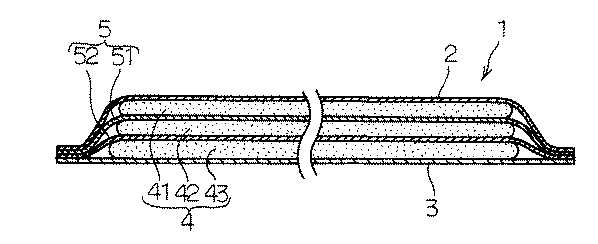
而して、本実施形態の加温具1において、図1及び2に示すように、前記発熱体4は、その厚み方向に積層された複数の発熱体層からなり、各発熱体層は、それぞれ通気性シート5を介して分離されている。
【0008】
更に詳述すると、本実施形態において発熱体層は、表面側に位置する第1発熱体層41と、中間に位置する第2発熱体層42と、裏面側に位置する第3発熱体層43との3層設けられている。
第1発熱体層41は、表面シート2と、表面シート2側に位置する第1通気性シート51とにより狭持されており、第2発熱体層42は、第1通気性シート51と裏面シート3側に位置する第2通気性シート52とにより狭持されており、第3発熱体層43は、第2通気性シート52と裏面シート3とにより狭持されている。
また、表面シート2、第1通気性シート51、第2通気性シート52及び裏面シート3は、それぞれ加温具1の外周縁において接合されている。
【0009】
そして、複数の発熱体層は、それぞれ異なる発熱性能を有するのが好ましい。尚、この好ましい実施形態に要求される発熱温度は、JIS S−4100の測定条件で40℃である。
具体的には、本実施形態においては、第1発熱体層41は、40℃に15分以内で到達し、最高到達温度が、55℃以下であり、40℃以上の温度を5〜60分間維持できる発熱性能を有する。
また、第2発熱体層42は、40℃に90分以内で到達し、最高到達温度が、50℃以下であり、40℃以上の温度を60分間以上維持できる発熱性能を有する。
また、第3発熱体層43は、40℃に60〜500分間で到達し、最高発熱温度が、45℃以下であり、40℃以上の温度を最大300分間維持できる発熱性能を有する。
これらの発熱性能は、複数ある発熱体層のうち、発熱特性を測定したい層以外の発熱体層から発熱体を取り除いた後、JIS S−4100により測定した値である。
【0010】
このように。各層の発熱性能を異ならせるためには、各層の充填量(面積当たり発熱体重量)を変更する手法、各層に用いる発熱剤の種類や配合割合を変更する手法、両者を組み合わせた手法等により異ならせることができる。
本実施形態においては、用いる発熱剤の種類や配合割合を変更せずに、充填量を変更することにより、各層の発熱性能を変更している。
また、発熱体層の充填量は、第1発熱体層41が、1〜15g/cm2 、第2発熱体層42が、5〜20g/cm2 、第3発熱体層43が、5〜20g/cm2 とするのが好ましく、発熱体4全体の厚さは、11〜30g/cm2 とするのが好ましい。
【0011】
また、表面シート2、第1通気性シート51、及び第2通気性シート52は、それぞれそれらの透湿度が異なる。
具体的には、本実施形態においては、表面シート2の透湿度は、200〜10000g/m2 ・dayとするのが好ましく、第1通気性シート51の透湿度は、50〜500g/m2 ・dayとするのが好ましく、第2通気性シート52の透湿度は、50〜2000g/m2 ・dayとするのが好ましい。
ここで、透湿度は、JIS Z−0208の透湿度測定方法により測定することができる。
【0012】
即ち、本発明の加温具においては、表面シート側に位置する発熱体層は、他の発熱体層に比して発熱性能が高く、且つ通気性シートよりも表面シートの方が透湿度が高いのが、好ましい。これにより、表面側に位置する発熱体層が加温具の使用開始後直ぐに所望の温度に達し、順次裏面シート側の発熱体層が所望の温度にまで昇温するので、使用者においては、使用開始後直ぐから所望の時間、所望の温度に発熱した状態で加温具を用いることができる。
【0013】
本発明に用いられる通気性シートとしては、特に制限はなく、不織布又は紙とフィルムとのラミネートフィルムや、フィルム、紙等必要な通気性能を持つ物であれば特に制限なく用いることができる。
フィルムの形成材料としては、ポリエチレン(PE)、ポリプロピレン(PP)、ナイロン等の熱可塑性高分子等が挙げられる。
また、不織布としては、PE、PP、ナイロン等の熱可塑性高分子単体からなる繊維、これらを用いた複合繊維又はこれらの混合繊維からなる不織布、さらにはセルロース繊維パルプ等を混合した物等が挙げられる。
また、紙としては、セルロース繊維パルプや熱可塑性高分子からなる合成パルプあるいはこれらの混合パルプを抄紙したもの等が挙げられる。
また、表面シートの形成材料も同じものを用いることができる。
また、これらの形成材料は、上述の透湿度に応じて、適宜選択される。
【0014】
前記発熱剤としては、空気の存在下で発熱するものであれば、特に限定されず、例えば鉄粉等の金属粉に、NaCl、KCl、MgCl2 、CaCl2 等の金属塩化物、K2 SO4 、Na2 SO4 、MgSO4 等の金属硫酸塩、または他の反応助剤となりうる化合物、水および水を良く吸収する保湿剤(例えば、活性炭、シリカゲル、木粉、吸水ポリマー等)並びに、必要に応じてバーミキュライト等の添加剤等を混合した混合物が用いられる。
また、各層に用いる発熱剤は、必要とされる発熱性能に応じて適宜選択される。
【0015】
また、裏面シートには、非通気シートが用いられる。
【0016】
本実施形態の加温具は、常法に準じて、表面シートと裏面シートと各通気性シートとを重ね合わせた後、それらの3辺をヒートシールなどして封止し、次いで、各シート間に発熱剤を注入し、最終に、残りの1辺を封止する等して得られる。
【0017】
本発明の加温具は、短時間で所望の温度に達するとともに、長時間の所望の温度を維持できるものであり、この性能は、各発熱体層の発熱性能を異なるものとした場合に顕著であり、この場合には、比較的短時間で発熱し高温に達するが短時間で発熱が終了うる層と、高温に達するには比較的時間を要するが長時間の発熱を維持する層が積層されているので、全体としては両方の発熱を合計した発熱性能が得られ、短時間で高温に達するとともに、長時間発熱を維持できる。
【0018】
本発明の加温具は、通常の使い捨てカイロ、各種の痛み緩和用発熱体、食品や薬品の加熱用具等に適用できる。
なお、本発明の加温具は、上述の実施形態のように長方形状でなく、円形や不定形状でも良い。
また、各発熱体層は、それぞれ同じ発熱性能としても良い。
【0019】
【実施例】
〔実施例1〕
鉄粉(同和産業製、商品名「RKH」)57wt%、5wt%食塩水29wt%、活性炭1.4wt%、バーミキュライト5.8wt%、吸水ポリマー(三菱化学製、商品名「アクアパール AIB」)4.2wt%、珪酸カルシウム2.6wt%を混合して発熱剤を得た。
また、表面シートとして、透湿シート(透湿度4300g/m2 ・day、三井化学(株)製、商品名「KTF−40」)を用い、裏面シートとして、PEシートを用い、第1通気性シートとして、透湿度120g/m2 ・dayの透湿シートを用い、第2通気性シートとして、透湿度1000g/m2 ・dayの透湿シートを用いた。
そして、得られた発熱剤を、表面シートと第1通気性シートとの間に、第1発熱体層が4gとなるように、また、第1通気性シートと第2通気性シートとの間に、第2発熱体層が11gとなるように、更に、第2通気性シートと裏面シートとの間に第3発熱体層が14gとなるように、それぞれ介在させて、図1に示す加温具を作製した(発熱体の大きさ:10cm×12cm×1.5mm、即ち、厚み1.5mm)。
得られた加温具を発熱させて、JIS S−4100の温度特性測定方法により裏面シート側の発熱評価を行った。この結果を〔表1〕に示す。
【0020】
〔比較例1及び2〕
発熱剤の量を28gとし、通気性シートを用いずに、発熱体層を1層のみとし、更に表面シートの透湿度を、比較例1においては、120g/m2 ・dayとし、比較例2においては、200g/m2 ・dayとした以外は、実施例1と同様にして加温具を得、得られた加温具を用いて、実施例1と同様に評価を行った。その結果を〔表1〕に示す。
【0021】
【表1】
〔表1〕に示す結果から明らかなように、実施例1の加温具は、比較例の加温具に比べて、短時間で高温(40℃)に達すると共に、40℃以上の温度を長時間保持していることが判る。
【0023】
【発明の効果】
本発明の加温具は、短時間で、温度が上がりすぎることなく所望の温度まで発熱し、しかもこの温度を長時間維持することができるものである。
【図面の簡単な説明】
【図1】図1は、本発明の加温具の1実施形態を示す斜視図である。
【図2】図2は、図1のX−X断面を模式的に示す断面図である。
【符号の説明】
1 加温具
2 通気シート
3 裏面シート
4 発熱体
41 第1発熱体層
42 第2発熱体層
43 第3発熱体層
5 通気性シート
51 第1通気性シート
52 第2通気性シート[0001]
BACKGROUND OF THE INVENTION
The present invention relates to a heating device such as a disposable body warmer that generates heat to an appropriate temperature in a short time and can maintain the appropriate temperature for a long time.
[0002]
[Prior art and problems to be solved by the invention]
In a heating device such as a conventional disposable warmer, the heating element is formed by sealing a heat generating agent that generates heat by reacting with oxygen in the air between the breathable sheet and the back sheet when it comes into contact with air.
As the performance required for this heating element, two important things are to reach the required temperature as quickly as possible after the start of use and to maintain the required temperature for as long as possible.
[0003]
For this reason, in order to generate heat to a desired temperature in a relatively short time, the filled exothermic agent is reacted with air at a high speed, specifically, a method for increasing the moisture permeability of the ventilation sheet, and more reaction as an exothermic agent. A high-speed exothermic agent, for example, a method using a material having a large specific surface area as a component such as iron powder that reacts with air to generate heat has been proposed.
However, these methods cannot be used in a relatively short time because the entire sealed exothermic agent does not react with air in a short time. In addition, the maximum temperature reached may be too high relative to the desired temperature.
In order to improve these problems, it may be possible to further increase the filling amount of the heat generating agent, but in this case, the heating element becomes thick and irritating, making it uncomfortable or difficult to carry, and extending the heat generation time. However, the maximum temperature is still too high.
[0004]
Accordingly, an object of the present invention is to provide a warming tool that generates heat to a desired temperature in a short time without excessively increasing the temperature and can maintain this temperature for a long time.
[0005]
[Means for Solving the Problems]
The present invention, between the breathable topsheet and the air-impermeable backsheet made by interposing a heating element which generates heat in contact with air, the heating element has a plurality of which are stacked in the thickness direction thereof Each heating element layer is composed of heating element layers, and each heating element layer achieves the above-mentioned object by providing a heating tool in which the heating element layers are separated from each other through a breathable sheet. Is.
[0006]
DETAILED DESCRIPTION OF THE INVENTION
Hereinafter, a preferred embodiment of the heating device of the present invention will be described.
As shown in FIGS. 1 and 2, the heating device 1 of the present embodiment includes a heating element 4 that generates heat in contact with air between a
The heating device 1 of this embodiment is formed by enclosing a heating element 4 described later between a rectangular back sheet 3 and a
[0007]
Thus, in the heating device 1 of the present embodiment, as shown in FIGS. 1 and 2, the heating element 4 is composed of a plurality of heating element layers stacked in the thickness direction, and each heating element layer includes: Each is separated via a
[0008]
More specifically, in the present embodiment, the heating element layer includes a first heating element layer 41 located on the front surface side, a second heating element layer 42 located in the middle, and a third heating element layer 43 located on the back side. And three layers are provided.
The first heating element layer 41 is sandwiched between the
Further, the
[0009]
The plurality of heating element layers preferably have different heat generation performances. The exothermic temperature required for this preferred embodiment is 40 ° C. under the measurement conditions of JIS S-4100.
Specifically, in the present embodiment, the first heating element layer 41 reaches 40 ° C. within 15 minutes, the maximum reached temperature is 55 ° C. or less, and the temperature of 40 ° C. or more is set for 5 to 60 minutes. It has heat generation performance that can be maintained.
Further, the second heating element layer 42 reaches 40 ° C. within 90 minutes, has a maximum temperature of 50 ° C. or less, and has a heat generation performance capable of maintaining a temperature of 40 ° C. or more for 60 minutes or more.
The third heating element layer 43 reaches 40 ° C. in 60 to 500 minutes, has a maximum heat generation temperature of 45 ° C. or less, and has a heat generation performance capable of maintaining a temperature of 40 ° C. or more for a maximum of 300 minutes.
These heat generation performances are values measured according to JIS S-4100 after removing the heat generation elements from the heat generation element layers other than the layer for which the heat generation characteristics are to be measured among the plurality of heat generation element layers.
[0010]
in this way. In order to vary the heat generation performance of each layer, it differs depending on the method of changing the filling amount (heater weight per area) of each layer, the method of changing the type and mixing ratio of the heat generating agent used in each layer, the method of combining both, etc. Can be made.
In the present embodiment, the heat generation performance of each layer is changed by changing the filling amount without changing the type and blending ratio of the heat generating agent to be used.
In addition, the filling amount of the heating element layer is such that the first heating element layer 41 is 1 to 15 g / cm 2 , the second heating element layer 42 is 5 to 20 g / cm 2 , and the third heating element layer 43 is 5 to 5 g / cm 2 . it is preferable to be 20 g / cm 2, the total thickness of the heating member 4 is preferably set to 11~30g / cm 2.
[0011]
Further, the
Specifically, in this embodiment, the moisture permeability of the
Here, the moisture permeability can be measured by a moisture permeability measuring method of JIS Z-0208.
[0012]
That is, in the heating device of the present invention, the heating element layer located on the top sheet side has higher heat generation performance than the other heating element layers, and the top sheet has a moisture permeability more than the breathable sheet. High is preferred. As a result, the heating element layer located on the surface side reaches a desired temperature immediately after the start of use of the heating tool, and the heating element layer on the back sheet side is sequentially heated to the desired temperature. The heating tool can be used in a state where heat is generated at a desired temperature for a desired time immediately after the start of use.
[0013]
There is no restriction | limiting in particular as an air permeable sheet used for this invention, If it is a thing with required air permeability, such as a nonwoven fabric or the laminated film of a paper and a film, a film, paper, it can use without a restriction | limiting in particular.
Examples of the film forming material include thermoplastic polymers such as polyethylene (PE), polypropylene (PP), and nylon.
In addition, examples of the nonwoven fabric include fibers made of a single thermoplastic polymer such as PE, PP, and nylon, composite fibers using these, nonwoven fabric made of a mixed fiber thereof, and a mixture of cellulose fiber pulp and the like. It is done.
Examples of the paper include cellulose fiber pulp, synthetic pulp made of a thermoplastic polymer, or paper made from a mixed pulp thereof.
Moreover, the same material can be used for the surface sheet.
Moreover, these forming materials are suitably selected according to the above-mentioned moisture permeability.
[0014]
The exothermic agent is not particularly limited as long as it generates heat in the presence of air, and for example, metal powder such as iron powder, metal chloride such as NaCl, KCl, MgCl 2 , CaCl 2 , K 2 SO 4 , metal sulfates such as Na 2 SO 4 , MgSO 4 , or other compounds that can serve as reaction aids, water and humectants that absorb water well (eg, activated carbon, silica gel, wood flour, water-absorbing polymers, etc.), and A mixture in which an additive such as vermiculite is mixed as necessary is used.
Moreover, the heat generating agent used for each layer is appropriately selected according to the required heat generation performance.
[0015]
Moreover, a non-breathable sheet is used for the back sheet.
[0016]
In the heating device of this embodiment, according to a conventional method, after superposing the top sheet, the back sheet and each breathable sheet, the three sides are sealed by heat sealing or the like, and then each sheet It is obtained by injecting an exothermic agent between them and finally sealing the remaining one side.
[0017]
The heating device of the present invention can reach a desired temperature in a short time and maintain the desired temperature for a long time, and this performance is remarkable when the heat generation performance of each heating element layer is different. In this case, a layer that generates heat in a relatively short time and reaches a high temperature but can finish heat generation in a short time and a layer that requires a relatively long time to reach a high temperature but maintains a long time heat generation are laminated. Therefore, as a whole, the heat generation performance obtained by adding both heat generations can be obtained, the temperature can be increased in a short time, and the heat generation can be maintained for a long time.
[0018]
The heating device of the present invention can be applied to ordinary disposable warmers, various pain relief heating elements, food and medicine heating tools, and the like.
In addition, the heating tool of this invention may be circular or indefinite shape instead of rectangular shape like the above-mentioned embodiment.
Further, each heating element layer may have the same heat generation performance.
[0019]
【Example】
[Example 1]
Iron powder (made by Dowa Sangyo Co., Ltd., trade name “RKH”) 57 wt%, 5 wt% saline solution 29 wt%, activated carbon 1.4 wt%, vermiculite 5.8 wt%, water-absorbing polymer (Made by Mitsubishi Chemical, trade name “Aqua Pearl AIB”) An exothermic agent was obtained by mixing 4.2 wt% and calcium silicate 2.6 wt%.
In addition, a moisture permeable sheet (moisture permeability of 4300 g / m 2 · day, manufactured by Mitsui Chemicals, Inc., trade name “KTF-40”) is used as the top sheet, and a PE sheet is used as the back sheet. A moisture permeable sheet having a moisture permeability of 120 g / m 2 · day was used as the sheet, and a moisture permeable sheet having a moisture permeability of 1000 g / m 2 · day was used as the second breathable sheet.
The obtained exothermic agent is placed between the top sheet and the first breathable sheet so that the first heating element layer is 4 g, and between the first breathable sheet and the second breathable sheet. In addition, the second heating element layer is 11 g, and the third heating element layer is 14 g between the second breathable sheet and the back sheet, respectively. A warming tool was produced (size of heating element: 10 cm × 12 cm × 1.5 mm, ie, thickness 1.5 mm).
The obtained heating tool was heated, and the heat generation on the back sheet side was evaluated by the temperature characteristic measurement method of JIS S-4100. The results are shown in [Table 1].
[0020]
[Comparative Examples 1 and 2]
The amount of the heat generating agent was 28 g, without using a breathable sheet, only one heating element layer, and the moisture permeability of the top sheet was 120 g / m 2 · day in Comparative Example 1, and Comparative Example 2 In Example 1, except that it was set to 200 g / m 2 · day, a heating device was obtained in the same manner as in Example 1, and evaluation was performed in the same manner as in Example 1 using the obtained heating device. The results are shown in [Table 1].
[0021]
[Table 1]
As is apparent from the results shown in [Table 1], the heating device of Example 1 reaches a high temperature (40 ° C.) in a short time and has a temperature of 40 ° C. or higher as compared with the heating device of the comparative example. It can be seen that it is held for a long time.
[0023]
【The invention's effect】
The heating device of the present invention generates heat up to a desired temperature in a short time without excessively increasing the temperature, and can maintain this temperature for a long time.
[Brief description of the drawings]
FIG. 1 is a perspective view showing one embodiment of a heating device of the present invention.
FIG. 2 is a cross-sectional view schematically showing an XX cross section of FIG. 1;
[Explanation of symbols]
DESCRIPTION OF SYMBOLS 1
Claims (3)
前記発熱体は、その厚み方向に積層された複数の発熱体層からなり、各発熱体層は、隣接する発熱体層との間が、それぞれ通気性シートを介して通気可能に分離されている加温具。Between the breathable top sheet and the non-breathable back sheet, there is a heating element that generates heat in contact with air ,
The heating element is composed of a plurality of heating element layers laminated in the thickness direction, and each heating element layer is separated from an adjacent heating element layer through a breathable sheet so as to allow ventilation. Heating tool.
Priority Applications (1)
| Application Number | Priority Date | Filing Date | Title |
|---|---|---|---|
| JP17222099A JP3628552B2 (en) | 1999-06-18 | 1999-06-18 | Heating equipment |
Applications Claiming Priority (1)
| Application Number | Priority Date | Filing Date | Title |
|---|---|---|---|
| JP17222099A JP3628552B2 (en) | 1999-06-18 | 1999-06-18 | Heating equipment |
Publications (2)
| Publication Number | Publication Date |
|---|---|
| JP2001000230A JP2001000230A (en) | 2001-01-09 |
| JP3628552B2 true JP3628552B2 (en) | 2005-03-16 |
Family
ID=15937831
Family Applications (1)
| Application Number | Title | Priority Date | Filing Date |
|---|---|---|---|
| JP17222099A Expired - Fee Related JP3628552B2 (en) | 1999-06-18 | 1999-06-18 | Heating equipment |
Country Status (1)
| Country | Link |
|---|---|
| JP (1) | JP3628552B2 (en) |
Cited By (1)
| Publication number | Priority date | Publication date | Assignee | Title |
|---|---|---|---|---|
| JP2009142558A (en) * | 2007-12-17 | 2009-07-02 | Kao Corp | Heating tool |
Families Citing this family (6)
| Publication number | Priority date | Publication date | Assignee | Title |
|---|---|---|---|---|
| JPWO2006006662A1 (en) | 2004-07-14 | 2008-05-01 | マイコール株式会社 | Heating element |
| JP2010057819A (en) * | 2008-09-05 | 2010-03-18 | Asahi Planning Co Ltd | Aromatic body warmer |
| US20120232621A1 (en) * | 2011-03-10 | 2012-09-13 | Kriksunov Leo B | Thermal treatment device with variable heat distribution |
| EP2911720B1 (en) * | 2012-10-29 | 2020-01-08 | Forever Young International, Inc. | Temperature changing intracorporeal fluid delivery devices |
| JP7433759B2 (en) * | 2018-11-27 | 2024-02-20 | 小林製薬株式会社 | heating equipment |
| JP2020192309A (en) * | 2019-05-24 | 2020-12-03 | 花王株式会社 | Steam generator and heater |
-
1999
- 1999-06-18 JP JP17222099A patent/JP3628552B2/en not_active Expired - Fee Related
Cited By (1)
| Publication number | Priority date | Publication date | Assignee | Title |
|---|---|---|---|---|
| JP2009142558A (en) * | 2007-12-17 | 2009-07-02 | Kao Corp | Heating tool |
Also Published As
| Publication number | Publication date |
|---|---|
| JP2001000230A (en) | 2001-01-09 |
Similar Documents
| Publication | Publication Date | Title |
|---|---|---|
| EP1655005A1 (en) | Warming tool in a sheet form | |
| CN100387207C (en) | Thermal Therapy Appliances | |
| CN111887521A (en) | Steam warm mask | |
| JPWO2006006662A1 (en) | Heating element | |
| JP2011136060A (en) | Nasal region heating implement for mask | |
| EP1121912A2 (en) | Heating packet | |
| CN108135735A (en) | Vapor generates body and warm utensil | |
| JP3628552B2 (en) | Heating equipment | |
| CN111836603B (en) | Warming appliance | |
| WO2018230651A1 (en) | Heating body and method for manufacturing same | |
| WO2020137692A1 (en) | Mask | |
| CN112996407A (en) | Foot warming plaster | |
| KR20220157460A (en) | heating bulb | |
| JP2006340928A (en) | Device to improve flesh color around eye | |
| JP2009142507A (en) | Steam generator | |
| JP2001137275A (en) | Skin-applicable exothermic sheet | |
| JP7328258B2 (en) | heating tool | |
| JP5404106B2 (en) | Hot water tool, hot water kit including the hot water tool, and hot water device | |
| JP4295410B2 (en) | Disposable body warmers | |
| JP7414846B2 (en) | heating equipment | |
| TWI871956B (en) | Warming utensils | |
| JP3695991B2 (en) | Heating equipment | |
| JP2022089420A (en) | Warmer | |
| JPH0614742Y2 (en) | Chemical fever | |
| KR20230121929A (en) | heating bulb |
Legal Events
| Date | Code | Title | Description |
|---|---|---|---|
| A977 | Report on retrieval |
Free format text: JAPANESE INTERMEDIATE CODE: A971007 Effective date: 20040122 |
|
| A131 | Notification of reasons for refusal |
Free format text: JAPANESE INTERMEDIATE CODE: A131 Effective date: 20040203 |
|
| A521 | Written amendment |
Free format text: JAPANESE INTERMEDIATE CODE: A523 Effective date: 20040401 |
|
| A521 | Written amendment |
Free format text: JAPANESE INTERMEDIATE CODE: A523 Effective date: 20040416 |
|
| A131 | Notification of reasons for refusal |
Free format text: JAPANESE INTERMEDIATE CODE: A131 Effective date: 20040706 |
|
| A521 | Written amendment |
Free format text: JAPANESE INTERMEDIATE CODE: A523 Effective date: 20040902 |
|
| TRDD | Decision of grant or rejection written | ||
| A01 | Written decision to grant a patent or to grant a registration (utility model) |
Free format text: JAPANESE INTERMEDIATE CODE: A01 Effective date: 20041207 |
|
| A61 | First payment of annual fees (during grant procedure) |
Free format text: JAPANESE INTERMEDIATE CODE: A61 Effective date: 20041208 |
|
| FPAY | Renewal fee payment (event date is renewal date of database) |
Free format text: PAYMENT UNTIL: 20071217 Year of fee payment: 3 |
|
| FPAY | Renewal fee payment (event date is renewal date of database) |
Free format text: PAYMENT UNTIL: 20081217 Year of fee payment: 4 |
|
| FPAY | Renewal fee payment (event date is renewal date of database) |
Free format text: PAYMENT UNTIL: 20081217 Year of fee payment: 4 |
|
| FPAY | Renewal fee payment (event date is renewal date of database) |
Free format text: PAYMENT UNTIL: 20091217 Year of fee payment: 5 |
|
| FPAY | Renewal fee payment (event date is renewal date of database) |
Free format text: PAYMENT UNTIL: 20091217 Year of fee payment: 5 |
|
| FPAY | Renewal fee payment (event date is renewal date of database) |
Free format text: PAYMENT UNTIL: 20101217 Year of fee payment: 6 |
|
| FPAY | Renewal fee payment (event date is renewal date of database) |
Free format text: PAYMENT UNTIL: 20101217 Year of fee payment: 6 |
|
| FPAY | Renewal fee payment (event date is renewal date of database) |
Free format text: PAYMENT UNTIL: 20111217 Year of fee payment: 7 |
|
| FPAY | Renewal fee payment (event date is renewal date of database) |
Free format text: PAYMENT UNTIL: 20111217 Year of fee payment: 7 |
|
| FPAY | Renewal fee payment (event date is renewal date of database) |
Free format text: PAYMENT UNTIL: 20121217 Year of fee payment: 8 |
|
| FPAY | Renewal fee payment (event date is renewal date of database) |
Free format text: PAYMENT UNTIL: 20121217 Year of fee payment: 8 |
|
| FPAY | Renewal fee payment (event date is renewal date of database) |
Free format text: PAYMENT UNTIL: 20131217 Year of fee payment: 9 |
|
| R250 | Receipt of annual fees |
Free format text: JAPANESE INTERMEDIATE CODE: R250 |
|
| R250 | Receipt of annual fees |
Free format text: JAPANESE INTERMEDIATE CODE: R250 |
|
| R250 | Receipt of annual fees |
Free format text: JAPANESE INTERMEDIATE CODE: R250 |
|
| LAPS | Cancellation because of no payment of annual fees |