JP5620161B2 - Manufacturing method of heating element - Google Patents
Manufacturing method of heating element Download PDFInfo
- Publication number
- JP5620161B2 JP5620161B2 JP2010140014A JP2010140014A JP5620161B2 JP 5620161 B2 JP5620161 B2 JP 5620161B2 JP 2010140014 A JP2010140014 A JP 2010140014A JP 2010140014 A JP2010140014 A JP 2010140014A JP 5620161 B2 JP5620161 B2 JP 5620161B2
- Authority
- JP
- Japan
- Prior art keywords
- heating element
- sheet
- coating
- electrolyte
- paint
- Prior art date
- Legal status (The legal status is an assumption and is not a legal conclusion. Google has not performed a legal analysis and makes no representation as to the accuracy of the status listed.)
- Active
Links
Images

Classifications
-
- A—HUMAN NECESSITIES
- A61—MEDICAL OR VETERINARY SCIENCE; HYGIENE
- A61F—FILTERS IMPLANTABLE INTO BLOOD VESSELS; PROSTHESES; DEVICES PROVIDING PATENCY TO, OR PREVENTING COLLAPSING OF, TUBULAR STRUCTURES OF THE BODY, e.g. STENTS; ORTHOPAEDIC, NURSING OR CONTRACEPTIVE DEVICES; FOMENTATION; TREATMENT OR PROTECTION OF EYES OR EARS; BANDAGES, DRESSINGS OR ABSORBENT PADS; FIRST-AID KITS
- A61F7/00—Heating or cooling appliances for medical or therapeutic treatment of the human body
- A61F7/08—Warming pads, pans or mats; Hot-water bottles
-
- B—PERFORMING OPERATIONS; TRANSPORTING
- B32—LAYERED PRODUCTS
- B32B—LAYERED PRODUCTS, i.e. PRODUCTS BUILT-UP OF STRATA OF FLAT OR NON-FLAT, e.g. CELLULAR OR HONEYCOMB, FORM
- B32B15/00—Layered products comprising a layer of metal
- B32B15/14—Layered products comprising a layer of metal next to a fibrous or filamentary layer
-
- B—PERFORMING OPERATIONS; TRANSPORTING
- B32—LAYERED PRODUCTS
- B32B—LAYERED PRODUCTS, i.e. PRODUCTS BUILT-UP OF STRATA OF FLAT OR NON-FLAT, e.g. CELLULAR OR HONEYCOMB, FORM
- B32B5/00—Layered products characterised by the non- homogeneity or physical structure, i.e. comprising a fibrous, filamentary, particulate or foam layer; Layered products characterised by having a layer differing constitutionally or physically in different parts
- B32B5/22—Layered products characterised by the non- homogeneity or physical structure, i.e. comprising a fibrous, filamentary, particulate or foam layer; Layered products characterised by having a layer differing constitutionally or physically in different parts characterised by the presence of two or more layers which are next to each other and are fibrous, filamentary, formed of particles or foamed
- B32B5/30—Layered products characterised by the non- homogeneity or physical structure, i.e. comprising a fibrous, filamentary, particulate or foam layer; Layered products characterised by having a layer differing constitutionally or physically in different parts characterised by the presence of two or more layers which are next to each other and are fibrous, filamentary, formed of particles or foamed one layer being formed of particles, e.g. chips, granules, powder
-
- C—CHEMISTRY; METALLURGY
- C09—DYES; PAINTS; POLISHES; NATURAL RESINS; ADHESIVES; COMPOSITIONS NOT OTHERWISE PROVIDED FOR; APPLICATIONS OF MATERIALS NOT OTHERWISE PROVIDED FOR
- C09K—MATERIALS FOR MISCELLANEOUS APPLICATIONS, NOT PROVIDED FOR ELSEWHERE
- C09K5/00—Heat-transfer, heat-exchange or heat-storage materials, e.g. refrigerants; Materials for the production of heat or cold by chemical reactions other than by combustion
Description
本発明は、発熱体の製造方法に関する。 The present invention relates to a method for manufacturing a heating element.
被酸化性金属を含む発熱組成物を、吸水性を有するシートと積層してなる発熱体の技術が知られている。例えば、インキ状ないしクリーム状の発熱組成物がシート状包材内に積層・封入されてなる発熱体において、該包材として一部が通気性及び吸水性を有するものを用い、かつインキ状ないしクリーム状の発熱組成物の水分の一部を該包材に吸収させた発熱体が提案されている(特許文献1参照)。この発熱組成物においては、過剰の水や、遊離水及び/又は含水ゲルが、空気に対するバリヤー層としての機能を発現し、該バリヤー層によって発熱反応が抑制されている。このバリヤー層は、過剰の水等が吸水性を有する前記の包材に吸収されることで消失し、それによって発熱が進行するようになる。 A heating element technology is known in which a heat generating composition containing an oxidizable metal is laminated with a sheet having water absorption. For example, in a heating element in which an ink-like or cream-like exothermic composition is laminated and enclosed in a sheet-like packaging material, a part of the packaging material having air permeability and water absorption is used, and A heating element has been proposed in which a part of the moisture of the creamy exothermic composition is absorbed by the packaging material (see Patent Document 1). In this exothermic composition, excess water, free water and / or a hydrogel exhibits a function as a barrier layer against air, and the exothermic reaction is suppressed by the barrier layer. The barrier layer disappears when excess water or the like is absorbed by the packaging material having water absorption, and heat generation proceeds accordingly.
また、本出願人は、先に、被酸化性金属粉末、繊維材料、水及び保水剤を含み且つ水の含有量が40〜75重量%である塗工液を支持体上に塗工して含水成形体を形成し、該含水成形体を所定の含水率まで脱水した後、脱水された該含水成形体を所定の含水率まで加熱乾燥させて中間成形体を得、然る後、該中間成形体に電解質水溶液を所定量付与して発熱成形体となす発熱成形体の製造方法を提案した(特許文献2)。 In addition, the applicant previously applied a coating liquid containing an oxidizable metal powder, a fiber material, water and a water retention agent and having a water content of 40 to 75% by weight on a support. After forming a water-containing molded body and dehydrating the water-containing molded body to a predetermined moisture content, the dehydrated water-containing molded body is heated and dried to a predetermined moisture content to obtain an intermediate molded body. A method for producing a heat generating molded body was proposed in which a predetermined amount of an aqueous electrolyte solution was applied to the molded body to form a heat generating molded body (Patent Document 2).
しかし、特許文献1に記載の技術においては、含水状態となっており粘性を有する発熱組成物を、通気性を有するシートと直接積層させたり、粘性を有する状態で通気性を有するシートを被覆しているので、該発熱組成物の粘性によって該シートの通気性が損なわれやすく、その結果、均一な発熱反応が起こりにくい。また、発熱組成物の層が形成されているシートは包材であり、使用者の動作が発熱組成物の層に直接伝達し、それによって発熱組成物の層の脱落が起こりやすい。
また、特許文献1に記載の技術においては、発熱組成物を攪拌混練して形成する際に、過剰水により発熱抑制効果はあるが、食塩(電解質)及び鉄粉を同時に攪拌混練するため、混練機のパドルやタンク壁面等に附着した塗料は水分を失うことで激しく酸化反応を起こすため、製造機器はチタンなどの耐食性の高い高価な材料を使用しなければならず、高額な設備投資が必要になる。
また、特許文献1に記載の発熱体の製造方法においては、食塩(電解質)及び鉄粉を同時に攪拌混練するため、得られた発熱組成物に成分の沈降や離水が生じ易く、発熱組成物中の成分の分散性を維持することが難しかった。
However, in the technique described in
Further, in the technique described in
Moreover, in the manufacturing method of the heat generating body described in
他方、特許文献2に記載の発熱成形体の製造方法によれば、塗工液中に電解質が含まれていないので、塗工液を塗工する際や、脱水・乾燥させて中間成形体を得る際に、被酸化性金属粉末の酸化が進行し難く、塗料中の成分が良好な分散性を維持することができる。 On the other hand, according to the method for producing the exothermic molded body described in Patent Document 2, since the electrolyte is not contained in the coating liquid, the intermediate molded body is formed by dehydrating and drying the coating liquid. When obtained, the oxidation of the oxidizable metal powder is difficult to proceed, and the components in the coating can maintain good dispersibility.
しかし、特許文献2の発熱成形体の製造方法は、脱水する工程や加熱乾燥する工程を有するため、製造工程が大きくなる傾向にある。他方、この脱水工程や加熱乾燥工程を省略した場合には、塗工液中の水分と電解質水溶液の水分とで、発熱体の表面がべたつき易くなり、製造設備のメンテナンスの負担が増大したり、通気性の包材で被覆した場合に該包材の目を塞いで所望の発熱性能を得にくくなる恐れがある。 However, since the manufacturing method of the exothermic molded object of patent document 2 has the process to spin-dry | dehydrate and the process to heat-dry, it exists in the tendency for a manufacturing process to become large. On the other hand, when this dehydration step and heat drying step are omitted, the surface of the heating element becomes easy to stick with the moisture in the coating liquid and the aqueous electrolyte solution, increasing the burden of maintenance on the production equipment, When covered with a breathable packaging material, the packaging material may be blocked, making it difficult to obtain desired heat generation performance.
したがって、本発明の課題は、前述した従来技術が有する欠点を解消し得る発熱体の製造方法を提供することにある。 Therefore , the subject of this invention is providing the manufacturing method of the heat generating body which can eliminate the fault which the prior art mentioned above has.
前記の課題を解決すべく本発明者らは鋭意検討した結果、高吸収性ポリマーを含む繊維シートを基材シートに用いるとともに、発熱組成物の層に含ませる被酸化性金属の粒子と電解質水溶液とを別工程で、被酸化性金属の粒子の先、電解質水溶液を後に添加することにより、塗料中の成分の分散性が維持され、また、製造工程における被酸化性金属の酸化を抑制して良好な発熱特性を有する発熱体を製造できるとともに、発熱体の発熱層の含水率もコントロールし易いことを知見した。 As a result of diligent investigations to solve the above problems, the present inventors have used a fiber sheet containing a superabsorbent polymer as a base sheet, and an oxidizable metal particle and an aqueous electrolyte solution to be contained in a layer of a heat generating composition. In a separate process, the dispersibility of the components in the coating is maintained by adding the tip of the oxidizable metal particles and the electrolyte aqueous solution later, and also suppresses the oxidation of the oxidizable metal in the manufacturing process. It has been found that a heating element having good heat generation characteristics can be produced, and that the moisture content of the heating layer of the heating element can be easily controlled.
本発明は前記の知見に基づきなされたものであり、被酸化性金属の粒子、電解質及び水を含む発熱組成物の層が、高吸収性ポリマーの粒子及び繊維材料を含む繊維シートからなる基材シートに設けられてなる発熱体の製造方法であって、前記基材シートの一面に、前記電解質を含まず前記被酸化性金属の粒子を含む塗料を塗工する塗工工程、及び前記塗料が塗工された前記基材シートに、前記電解質を含む電解質水溶液を添加する電解質添加工程を備える発熱体の製造方法を提供するものである。 The present invention has been made on the basis of the above-described knowledge, and the base material is composed of a fiber sheet in which a layer of a heat generating composition containing particles of an oxidizable metal, an electrolyte and water comprises particles of a superabsorbent polymer and a fiber material. A method of manufacturing a heating element provided on a sheet, wherein a coating step of applying a coating containing particles of the oxidizable metal not including the electrolyte on one surface of the base sheet, and the coating The manufacturing method of the heat generating body provided with the electrolyte addition process which adds the electrolyte aqueous solution containing the said electrolyte to the said base material sheet | seat coated is provided.
本発明の発熱体の製造方法によれば、塗料中の成分が良好な分散性を維持し、製造工程における被酸化性金属粉末の酸化を抑制して良好な発熱特性を有する発熱体を製造できるとともに、発熱体の発熱層の含水率をコントロールし易い。
本発明の発熱具の製造方法によれば、発熱体の包材に通気性シートを用いてもその通気性を阻害しにくく、または発熱組成物の層が脱落しにくく、発熱特性に優れた発熱具を製造することができる。
According to the method for producing a heating element of the present invention, it is possible to produce a heating element having good exothermic characteristics by maintaining good dispersibility of the components in the paint and suppressing oxidation of the oxidizable metal powder in the production process. At the same time, it is easy to control the moisture content of the heating layer of the heating element.
According to the method for producing a heating tool of the present invention, even when a breathable sheet is used as a packaging material for a heating element, the breathability is not hindered, or the layer of the heating composition is difficult to fall off, and the heat generation excellent in heat generation characteristics. Tools can be manufactured.
以下本発明を、その好ましい実施形態に基づき説明する。
本発明の発熱具の製造方法により製造される発熱具は、その構成部材として、発熱体と包材とを備える。本発明の発熱体の製造方法により製造される発熱体は、例えば、その発熱具の発熱体として好ましく用いられる。発熱具の構成部材としての発熱体は、その発熱具において熱を生じさせる部材である。他方、発熱具の包材は、発熱体の全体を包囲し、本発明の発熱具の外面をなす部材である。
Hereinafter, the present invention will be described based on preferred embodiments thereof.
The heating tool manufactured by the manufacturing method of the heating tool of the present invention includes a heating element and a packaging material as its constituent members. The heating element manufactured by the method for manufacturing a heating element of the present invention is preferably used as a heating element of the heating tool, for example. A heating element as a constituent member of a heating tool is a member that generates heat in the heating tool. On the other hand, the packaging material of the heating tool is a member that surrounds the entire heating element and forms the outer surface of the heating tool of the present invention.
先ず、本発明の発熱体の製造方法により製造される発熱体について説明する。
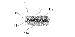
本発明の発熱体の製造方法により製造される発熱体は、基材シートと、該基材シートの一面に設けられた発熱組成物の層(以下、「発熱層」ともいう。)を備える。基材シートは、高吸収性ポリマーの粒子及び繊維材料を含む繊維シートから構成されている。発熱層は、被酸化性金属の粒子を含んで構成されている。
First, the heating element manufactured by the manufacturing method of the heating element of the present invention will be described.
A heating element manufactured by the method for manufacturing a heating element of the present invention includes a base sheet and a layer of a heat generating composition (hereinafter also referred to as “heating layer”) provided on one surface of the base sheet. The base sheet is composed of a fiber sheet containing superabsorbent polymer particles and a fiber material. The heat generating layer includes particles of an oxidizable metal.
繊維シートからなる基材シートは、(イ)高吸収性ポリマーの粒子と繊維材料とが均一に混合した状態の1枚のシートであり得る。また基材シートは、(ロ)高吸収性ポリマーの粒子が、該基材シートの厚み方向略中央域に主として存在しており、かつ該基材シートの表面には該粒子が実質的に存在していない構造を有するワンプライのものでもあり得る。更に基材シートは、(ハ)繊維材料を含む同一の又は異なる繊維シート間に、高吸収性ポリマーの粒子が配置された2枚の繊維シートの重ね合わせ体でもあり得る。これら種々の形態をとり得る基材シートのうち、発熱層の含水率のコントロールを容易に行い得る観点から、基材シートとして(ロ)の形態のものを用いることが好ましい。 The base sheet made of a fiber sheet may be (a) one sheet in a state where the particles of the superabsorbent polymer and the fiber material are uniformly mixed. In the base sheet, (b) the superabsorbent polymer particles are mainly present in a substantially central region in the thickness direction of the base sheet, and the particles are substantially present on the surface of the base sheet. It can also be one-ply with a structure that is not. Further, the base sheet may be (c) a laminate of two fiber sheets in which particles of a superabsorbent polymer are arranged between the same or different fiber sheets containing a fiber material. Of these base sheets that can take various forms, it is preferable to use the base sheet having the form (b) from the viewpoint of easily controlling the moisture content of the heat generating layer.
繊維シートからなる基材シートに含まれる繊維材料としては、親水性繊維及び疎水性繊維のいずれをも用いることができるが、親水性繊維を用いることが好ましい。親水性繊維としては、天然繊維及び合成繊維のいずれをも用いることができる。
基材シートの構成繊維として親水性繊維を用いることで、発熱層に含まれる被酸化性金属との間で水素結合が形成されやすくなり、発熱層の保形性が良好になるという利点がある。また、親水性繊維を用いることで、基材シートの吸水性ないし保水性が良好になり、発熱層の含水率をコントロールしやすくなるという利点もある。これらの観点から、親水性繊維としてはセルロース繊維を用いることが好ましい。セルロース繊維としては化学繊維(合成繊維)及び天然繊維を用いることができる。
As the fiber material contained in the base sheet made of a fiber sheet, both hydrophilic fibers and hydrophobic fibers can be used, but it is preferable to use hydrophilic fibers. As the hydrophilic fiber, any of natural fiber and synthetic fiber can be used.
By using hydrophilic fibers as the constituent fibers of the base sheet, there is an advantage that hydrogen bonds are easily formed with the oxidizable metal contained in the heat generating layer, and the shape retention of the heat generating layer is improved. . In addition, the use of hydrophilic fibers also has the advantage that the water absorption or water retention of the base sheet is improved and the water content of the heat generating layer can be easily controlled. From these viewpoints, cellulose fibers are preferably used as the hydrophilic fibers. Chemical fibers (synthetic fibers) and natural fibers can be used as the cellulose fibers.
セルロースの化学繊維としては、例えばレーヨン及びアセテートを用いることができる。一方、天然のセルロース繊維としては、各種の植物繊維、木材パルプ、非木材パルプ、木綿、麻、麦藁、ヘンプ、ジュート、カポック、やし、いぐさ等を用いることができる。これらのセルロース繊維のうち、太い繊維を容易に入手できる等の観点から、木材パルプを用いることが好ましい。セルロース繊維として太い繊維を用いることは、基材シートの吸水性ないし保水性や、発熱層の保持性等の観点から遊離である。 As chemical fibers of cellulose, for example, rayon and acetate can be used. On the other hand, as natural cellulose fiber, various plant fibers, wood pulp, non-wood pulp, cotton, hemp, wheat straw, hemp, jute, kapok, palm, rush, etc. can be used. Of these cellulose fibers, it is preferable to use wood pulp from the viewpoint that a thick fiber can be easily obtained. The use of thick fibers as the cellulose fibers is free from the viewpoints of water absorption or water retention of the base sheet, retention of the heat generating layer, and the like.
特に、セルロース天然繊維として、嵩高セルロース繊維を用いることが好ましい。嵩高セルロース繊維を用いることで、基材シートにおける構成繊維の繊維間距離を好適なものとすることが容易となる。嵩高セルロース繊維の具体例としては、(a)繊維形状が、捻れ構造、クリンプ構造、屈曲及び/若しくは分岐構造の立体構造をとるか、(b)繊維粗度が0.2mg/m以上であるか、又は(c)セルロース繊維の分子内及び分子間が架橋されたものが挙げられる。 In particular, it is preferable to use bulky cellulose fibers as the natural cellulose fibers. By using the bulky cellulose fiber, it becomes easy to make the inter-fiber distance of the constituent fibers in the base sheet suitable. As specific examples of the bulky cellulose fiber, (a) the fiber shape has a three-dimensional structure of a twisted structure, a crimped structure, a bent and / or branched structure, or (b) the fiber roughness is 0.2 mg / m or more. Or (c) those in which the intramolecular and intermolecular molecules of the cellulose fiber are crosslinked.
前記の(a)の捻れ構造、クリンプ構造、屈曲及び/又は分岐構造等の立体構造をとる繊維の具体例としては、木材パルプを化学的な反応で分解した化学パルプや、機械的な処理(叩解)で分解させたパルプや、化学的な反応と機械的な処理を組み合わせて得られたパルプを用いることができる。 Specific examples of the fiber having a three-dimensional structure such as a twisted structure, a crimped structure, a bent structure and / or a branched structure of (a) above include chemical pulp obtained by decomposing wood pulp by a chemical reaction, and mechanical treatment ( Pulp decomposed by beating) or pulp obtained by combining chemical reaction and mechanical treatment can be used.
前記の(b)の繊維は、嵩高な状態でセルロース繊維が集積し、それによって液体の移動抵抗が小さくなり、液体の透過速度が大きい。そのような繊維を用いると、後述する発熱体の製造の過程で、塗料を基材シートへ塗工した際に、該塗料中の水分が、基材シート中へ移動しやすくなるので、発熱層の含水率のコントロールが容易になる。また、発熱層を構成する固形分を保持し得る嵩高なネットワーク構造が形成され易い。これらの観点から、(b)の繊維の繊維粗度は、0.2〜2mg/m、特に0.3〜1mg/mであることが好ましい。 In the fiber (b), cellulose fibers are accumulated in a bulky state, whereby the movement resistance of the liquid is reduced, and the liquid permeation rate is high. When such a fiber is used, when the paint is applied to the base sheet in the process of manufacturing the heating element described later, moisture in the paint easily moves into the base sheet. It becomes easy to control the water content. In addition, a bulky network structure that can hold the solid content constituting the heat generating layer is easily formed. From these viewpoints, the fiber roughness of the fiber (b) is preferably 0.2 to 2 mg / m, particularly preferably 0.3 to 1 mg / m.
繊維粗度とは、木材パルプのように、繊維の太さが不均一な繊維において、繊維の太さを表す尺度として用いられるものであり、例えば、繊維粗度計(FS−200、KAJANNIELECTRONICSLTD.社製)を用いて測定される。繊維粗度が0.2mg/m以上のセルロース繊維の例としては、針葉樹クラフトパルプ〔Federal Paper Board Co.製の「ALBACEL」(商品名)、及びPT Inti Indorayon Utama製の「INDORAYON」(商品名)〕等が挙げられる。 The fiber roughness is used as a scale representing the fiber thickness in fibers having non-uniform fiber thickness, such as wood pulp. For example, a fiber roughness meter (FS-200, KAJANNIELECTRONICSLTD. ). Examples of cellulose fibers having a fiber roughness of 0.2 mg / m or more include softwood kraft pulp (“ALBACEL” (trade name) manufactured by Federal Paper Board Co. and “INDORAYON” (trade name) manufactured by PT Inti Indorayon Utama. )] And the like.
前記の(b)の繊維は、繊維断面の真円度が0.5〜1、特に0.55〜1であることが好ましい。このような真円度を有するセルロース繊維を用いることで、基材シートにおける液体の移動抵抗が一層小さくなり、液体の通過速度が一層大きくなる。真円度の測定方法は次の通りである。面積が変化しないように、繊維をその断面方向に垂直にスライスし、電子顕微鏡により断面写真をとる。断面写真を画像回析装置〔日本アビオニクス社製の「Avio EXCEL」(商品名)〕によって解析し、測定繊維の断面積及び周長を測定する。これらの値を用い、以下に示す式を用いて真円度を算出する。真円度は、任意の繊維断面を100点測定し、その平均値とする。
真円度=4π(測定繊維の断面積)/(測定繊維の断面の周長)2
The fiber (b) preferably has a roundness of the fiber cross section of 0.5 to 1, particularly 0.55 to 1. By using the cellulose fiber having such roundness, the movement resistance of the liquid in the base sheet is further reduced, and the passing speed of the liquid is further increased. The method for measuring roundness is as follows. The fiber is sliced perpendicular to the cross-sectional direction so that the area does not change, and a cross-sectional photograph is taken with an electron microscope. The cross-sectional photograph is analyzed by an image diffractometer [“Avio EXCEL” (trade name) manufactured by Nippon Avionics Co., Ltd.], and the cross-sectional area and circumference of the measurement fiber are measured. Using these values, the roundness is calculated using the following formula. The roundness is an average value obtained by measuring 100 arbitrary fiber cross sections.
Roundness = 4π (cross-sectional area of measurement fiber) / (peripheral length of cross-section of measurement fiber) 2
嵩高セルロース繊維として木材パルプを使用する場合、一般に木材パルプの断面は脱リグニン化処理によって偏平であり、その殆どの真円度は0.5未満であるところ、このような木材パルプの真円度を0.5以上にするためには、例えば、かかる木材パルプをマーセル化処理して木材パルプの断面を膨潤させればよい。市販のマーセル化パルプの例としては、ITT Rayonier Inc.製の「FILTRANIER」(商品名)や同社製の「POROSANIER」(商品名)等が挙げられる。 When wood pulp is used as the bulky cellulose fiber, the cross section of the wood pulp is generally flattened by delignification treatment, and most of the roundness is less than 0.5. In order to make it 0.5 or more, for example, the wood pulp may be mercerized to swell the cross section of the wood pulp. Examples of commercially available mercerized pulp include “FILTRANIER” (trade name) manufactured by ITT Rayonier Inc. and “POROSANIER” (trade name) manufactured by the same company.
前記の(c)の繊維である架橋セルロース繊維は、湿潤状態でも嵩高構造を維持し得るので好ましい。セルロース繊維を架橋するための方法としては、例えば、架橋剤を用いた架橋方法が挙げられる。かかる架橋剤の例としては、ジメチロールエチレン尿素及びジメチロールジヒドロキシエチレン尿素等のN−メチロール系化合物;クエン酸、トリカルバリル酸及びブタンテトラカルボン酸等のポリカルボン酸;ジメチルヒドロキシエチレン尿素等のポリオール;ポリグリシジルエーテル系化合物の架橋剤などが挙げられる。架橋剤の使用量は、セルロース繊維100重量部に対して、0.2〜20重量部とすることが好ましい。架橋セルロース繊維は、その繊維粗度が、0.1〜2mg/m、特に0.2〜1mg/mであることが好ましい。また架橋セルロース繊維は、繊維断面の真円度が0.5〜1、特に0.55〜1であることも好ましい。市販の架橋セルロース繊維としては、Weyerhaeuser Paper Co.製の「High Bulk Additive」等が挙げられる。 The crosslinked cellulose fiber as the fiber (c) is preferable because it can maintain a bulky structure even in a wet state. Examples of the method for crosslinking the cellulose fiber include a crosslinking method using a crosslinking agent. Examples of such crosslinking agents include N-methylol compounds such as dimethylolethyleneurea and dimethyloldihydroxyethyleneurea; polycarboxylic acids such as citric acid, tricarballylic acid and butanetetracarboxylic acid; polyols such as dimethylhydroxyethyleneurea A cross-linking agent for polyglycidyl ether compounds. The amount of the crosslinking agent used is preferably 0.2 to 20 parts by weight with respect to 100 parts by weight of the cellulose fiber. The crosslinked cellulose fiber has a fiber roughness of preferably 0.1 to 2 mg / m, particularly preferably 0.2 to 1 mg / m. The cross-linked cellulose fiber preferably has a roundness of the fiber cross section of 0.5 to 1, particularly 0.55 to 1. Examples of commercially available crosslinked cellulose fibers include “High Bulk Additive” manufactured by Weyerhaeuser Paper Co.
上述の(a)〜(c)の繊維のうち、特に(c)の繊維を用いると、基材シートと発熱層との一体性が高まり、該発熱層の脱落が起こりにくくなるという有利な効果が奏される。また発熱体が柔軟なものとなり、本発明の発熱具を取り付け対象物、例えば人体の皮膚や衣類に取り付けたときのフィット性が良好になるという有利な効果も奏される。意外なことに、発熱体の柔軟性は、発熱終了後においても維持されることは、特筆に値する。 Among the fibers (a) to (c) described above, particularly when the fiber (c) is used, the integrity of the base sheet and the heat generating layer is enhanced, and the advantageous effect that the heat generating layer is less likely to fall off. Is played. Further, the heating element becomes flexible, and there is an advantageous effect that the fitting property is improved when the heating tool of the present invention is attached to an object to be attached, for example, the skin or clothing of a human body. Surprisingly, it is worth noting that the flexibility of the heating element is maintained even after the end of heat generation.
上述の各種の親水性繊維は、その繊維長が0.5〜6mm、特に0.8〜4mmであることが、湿式法又は乾式法での基材シートの製造が容易である点から好ましい。 The above-mentioned various hydrophilic fibers preferably have a fiber length of 0.5 to 6 mm, particularly 0.8 to 4 mm, from the viewpoint of easy production of a substrate sheet by a wet method or a dry method.
基材シートには、上述の親水性繊維に加え、必要に応じて熱融着性繊維を配合してもよい。この繊維の配合によって、湿潤状態での基材シートの強度を高めることができる。熱融着性繊維の配合量は、基材シートにおける繊維の全量に対して0.1〜10質量%、特に0.5〜5質量%であることが好ましい。 In addition to the above-described hydrophilic fibers, heat-fusible fibers may be blended in the base sheet as necessary. By blending this fiber, the strength of the substrate sheet in a wet state can be increased. The compounding amount of the heat-fusible fiber is preferably 0.1 to 10% by mass, particularly 0.5 to 5% by mass, based on the total amount of fibers in the base sheet.
繊維シートからなる基材シートには、上述のとおり高吸収性ポリマーの粒子が含まれている。基材シートにおける高吸収性ポリマーの粒子の存在位置については先に述べたとおりである。高吸収性ポリマーとしては、自重の20倍以上の液体を吸収・保持でき且つゲル化し得るヒドロゲル材料を用いることが好ましい。粒子の形状は、球状、塊状、ブドウ房状、繊維状等であり得る。粒子の粒径は、1〜1000μm、特に10〜500μmであることが好ましい。高吸収性ポリマーの具体例としては、デンプン、架橋カルボキシルメチル化セルロース、アクリル酸又はアクリル酸アルカリ金属塩の重合体又は共重合体等、ポリアクリル酸及びその塩並びにポリアクリル酸塩グラフト重合体などが挙げられる。接合には、例えば高吸収性ポリマーの粒子を湿潤させることで生ずる粘性を利用することができる。また、繊維材料からなるウェブに対し、重合性モノマー及び/又は該モノマーの重合進行物を含有する液状体を付着させ、重合させて形成した高吸収性ポリマーの粒子を用いたものでもよい。この高吸収性ポリマーの粒子は、繊維材料に接合された状態になっている。
As described above, the base sheet made of the fiber sheet contains particles of the superabsorbent polymer. The location of the superabsorbent polymer particles in the base sheet is as described above. As the superabsorbent polymer, it is preferable to use a hydrogel material that can absorb and hold a liquid having a
基材シートに占める高吸収性ポリマーの割合は、10〜70質量%、特に20〜55質量%であることが、基材シートの吸水性ないし保水性を好適なものとする観点及び発熱層の含水率のコントロールの観点から好ましい。なお、この割合は、基材シート上に発熱層が形成される前の乾燥状態にある該基材シートについて測定された値である。 The ratio of the superabsorbent polymer in the base sheet is 10 to 70% by weight, particularly 20 to 55% by weight, and the viewpoint of making the water absorption or water retention of the base sheet suitable and the heat generating layer This is preferable from the viewpoint of controlling the water content. This ratio is a value measured for the base sheet in a dry state before the heat generation layer is formed on the base sheet.
基材シートは、その坪量が10〜200g/m2、特に35〜150g/m2であることが好ましい。基材シートの坪量をこの範囲内に設定することで、湿潤状態における基材シートの強度を十分に確保することができ、また基材シートの吸水性ないし保水性を好適なものとすることができる。一方、基材シートに含まれる高吸収性ポリマーの坪量は、5〜150g/m2、特に10〜100g/m2であることが好ましい。高吸収性ポリマーの坪量をこの範囲内に設定することで、基材シートの吸水性ないし保水性を一層好適なものとすることができる。また、発熱層の含水率を一層コントロールしやすくなる。これらの坪量は、基材シート上に発熱層が形成される前の乾燥状態にある該基材シートについて測定された値である。 The base sheet preferably has a basis weight of 10 to 200 g / m 2 , particularly 35 to 150 g / m 2 . By setting the basis weight of the base sheet within this range, sufficient strength of the base sheet in a wet state can be secured, and water absorption or water retention of the base sheet should be suitable. Can do. On the other hand, the basis weight of the superabsorbent polymer contained in the base sheet is preferably 5 to 150 g / m 2 , particularly 10 to 100 g / m 2 . By setting the basis weight of the superabsorbent polymer within this range, the water absorption or water retention of the base sheet can be further improved. Moreover, it becomes easier to control the moisture content of the heat generating layer. These basis weights are values measured for the base sheet in a dry state before the heat generation layer is formed on the base sheet.
基材シートは、それが前記の(イ)の形態のものである場合、例えばエアレイド法で製造することができる。(ロ)の形態のものである場合には、例えば本出願人の先の出願に係る特開平8−246395号公報に記載の湿式抄造法で製造することができる。(ハ)の形態のものであり場合には、エアレイド法又は湿式抄造法で製造することができる。 The substrate sheet can be produced by, for example, the airlaid method when it is in the form of (a). In the case of (b), it can be produced, for example, by the wet papermaking method described in JP-A-8-246395 related to the previous application of the present applicant. In the case of (c), it can be produced by the airlaid method or the wet papermaking method.
基材シートには、少なくともその一方の面に発熱層が設けられている。発熱層は、基材シートの一方の面にのみ設けられていてもよく、両面に設けられていてもよい。発熱層は、被酸化性金属の粒子、電解質及び水を含んでいる含水層である。発熱層は、更に反応促進剤を含んでいてもよい。発熱層は、基材シート上に存在していてもよく、あるいはその下部が基材シート中に埋没していてもよい。つまり、発熱層を構成する固形分の一部が、基材シートを構成する繊維シートに形成されている三次元状のネットワーク中に担持されていてもよい。発熱層の一部が基材シート中に埋没していることによって、発熱層と基材シートの一体性が増し、基材シートからの発熱層の脱落(使用前、使用中、使用後)が効果的に防止される。 The base sheet is provided with a heat generating layer on at least one surface thereof. The heat generating layer may be provided only on one side of the base sheet, or may be provided on both sides. The heat generating layer is a water-containing layer containing particles of an oxidizable metal, an electrolyte, and water. The heat generating layer may further contain a reaction accelerator. The heat generating layer may be present on the base sheet, or the lower part thereof may be buried in the base sheet. That is, a part of solid content constituting the heat generating layer may be carried in a three-dimensional network formed on the fiber sheet constituting the base sheet. Since part of the heat generation layer is embedded in the base sheet, the unity of the heat generation layer and the base sheet is increased, and the heat generation layer is removed from the base sheet (before, during, and after use). Effectively prevented.
発熱層に含まれる被酸化性金属としては、鉄、アルミニウム、亜鉛、マンガン、マグネシウム、カルシウム等が挙げられる。被酸化性金属の粒子の粒径は、例えば0.1〜300μm程度とすることができる。反応促進剤としては、水分保持剤として作用するほかに、被酸化性金属への酸素保持/供給剤としての機能も有しているものを用いることが好ましい。反応促進剤としては例えば活性炭(椰子殻炭、木炭粉、暦青炭、泥炭、亜炭)、カーボンブラック、アセチレンブラック、黒鉛、ゼオライト、パーライト、バーミキュライト、シリカ等が挙げられる。電解質としては、被酸化性金属の粒子の表面に形成された酸化物の溶解が可能なものが用いられる。その例としてはアルカリ金属、アルカリ土類金属又は遷移金属の硫酸塩、炭酸塩、塩化物又は水酸化物等が挙げられる。これらの中でも、導電性、化学的安定性、生産コストに優れる点からアルカリ金属、アルカリ土類金属又は遷移金属の塩化物が好ましく用いられ、特に塩化ナトリウム、塩化カリウム、塩化カルシウム、塩化マグネシウム、塩化第一鉄、塩化第二鉄が好ましく用いられる。 Examples of the oxidizable metal contained in the heat generating layer include iron, aluminum, zinc, manganese, magnesium, calcium and the like. The particle size of the oxidizable metal particles can be, for example, about 0.1 to 300 μm. As the reaction accelerator, it is preferable to use a reaction accelerator that has a function as an oxygen retention / supply agent for an oxidizable metal in addition to acting as a moisture retention agent. Examples of the reaction accelerator include activated carbon (coconut shell charcoal, charcoal powder, calendar bituminous coal, peat, lignite), carbon black, acetylene black, graphite, zeolite, perlite, vermiculite, silica and the like. As the electrolyte, an electrolyte capable of dissolving an oxide formed on the surface of the oxidizable metal particles is used. Examples thereof include alkali metal, alkaline earth metal or transition metal sulfates, carbonates, chlorides or hydroxides. Among these, chlorides of alkali metals, alkaline earth metals or transition metals are preferably used from the viewpoint of excellent conductivity, chemical stability and production cost, and particularly sodium chloride, potassium chloride, calcium chloride, magnesium chloride, chloride. Ferrous and ferric chloride are preferably used.
発熱体における被酸化性金属の量は、坪量で表して100〜3,000g/m2、特に200〜1,500g/m2であることが、十分な発熱量を確保する観点から好ましい。発熱体における反応促進剤の量は、4〜80g/m2、特に8〜50g/m2であることが、長時間にわたり安定な発熱を維持する観点から好ましい。同様の理由によって、発熱体における電解質の量は、4〜40g/m2、特に5〜30g/m2であることが好ましい。なお、これらの坪量は、基材シートに発熱層を片面に1層形成した場合での値である。したがって基材シートの両面に発熱層を形成した場合には、これらの坪量は上述の2倍の値となる。また、発熱体の具体的な用途に合わせ、坪量は適宜調整される。 The amount of oxidizable metal in the heating element, 100~3,000g / m 2 expressed as basis weight, to be particularly 200~1,500g / m 2, from the viewpoint of securing a sufficient heating value. The amount of the reaction accelerator in the heating element is preferably 4 to 80 g / m 2 , particularly 8 to 50 g / m 2 , from the viewpoint of maintaining stable heat generation for a long time. For the same reason, the amount of the electrolyte in the heating element is preferably 4 to 40 g / m 2 , particularly 5 to 30 g / m 2 . These basis weights are values in the case where one layer of heat generation layer is formed on one side of the base sheet. Therefore, when the heat generating layers are formed on both sides of the base sheet, these basis weights are double the above-mentioned values. Further, the basis weight is appropriately adjusted according to the specific application of the heating element.
上述したとおり発熱層は含水状態になっている。発熱層の含水率は、5〜50質量%、特に6〜40質量%であることが好ましい。発熱層の含水率をこの範囲内に設定することで、発熱層はその流動性が失われ、ひいては粘性が失われる。その結果、後述するように、発熱層の上側に通気性を有するシートを配置しても、該発熱層の貼り付きによって該シートの通気性が損なわれるという不都合が起こりにくくなる。発熱層の含水率は、基材シートの表面よりも上側に位置する部位を対象として測定される。したがって、発熱層のうち、基材シートに埋没している部位は、含水率の測定対象から除外される。発熱層の含水率の具体的な測定方法は次のとおりである。すなわち、基材シートの表面よりも上側に位置する部位の発熱層を窒素環境下で取り出し、その重量を測定する。その後、真空状態の105℃の温度の乾燥炉に2時間入れて水分を取り除き、再度、重量を測定し、含水量を測定する。
なお、上述の発熱層の含水率は、1つの発熱層あたりの値である。
As described above, the heat generating layer is in a water-containing state. The moisture content of the heat generating layer is preferably 5 to 50% by mass, particularly 6 to 40% by mass. By setting the moisture content of the heat generating layer within this range, the heat generating layer loses its fluidity and eventually loses its viscosity. As a result, as described later, even if a sheet having air permeability is arranged on the upper side of the heat generating layer, the inconvenience that the air permeability of the sheet is impaired by sticking of the heat generating layer is less likely to occur. The moisture content of the heat generating layer is measured with respect to a portion located above the surface of the base sheet. Therefore, the site | part embedded in the base material sheet among heat_generation | fever layers is excluded from the measuring object of a moisture content. A specific method for measuring the moisture content of the heat generating layer is as follows. That is, the exothermic layer at a portion located above the surface of the base sheet is taken out in a nitrogen environment, and its weight is measured. Then, it puts into a drying oven with a temperature of 105 ° C. in a vacuum state for 2 hours to remove moisture, measures the weight again, and measures the water content.
The moisture content of the heat generating layer is a value per heat generating layer.
発熱層の含水率を上述の範囲に設定することで、該発熱層がその上に配置される通気性シートへ貼り付くことが効果的に防止されるが、その分、発熱層に含まれる水の量が少なくなることに起因して発熱特性が低下するとの懸念が生じるかもしれない。しかし本発明においては、基材シートが水を含んでおり、発熱中に基材シートから発熱層へ水が供給されるので、発熱特性が低下することはない。特に、基材シートは高吸収性ポリマーを含んでおり、該高吸収性ポリマーからの水の放出は徐々に進行するので、発熱特性は長時間にわたって安定したものとなる。これらの観点から、発熱体における水が占める割合、つまり発熱体の含水率は、10〜60質量%、特に12〜50質量%であることが好ましい。発熱体の含水率の具体的な測定方法は次のとおりである。すなわち、窒素環境下で発熱体の重量を測定し、その後、真空状態の105℃の温度の乾燥炉に2時間入れて水分を取り除き、再度、重量を測定し、差分の重量を水分量として含水量を算出する。
なお、上述の発熱体の含水率は、基材シートに発熱層を1層形成した場合での値であるが、基材シートの各面に発熱層を形成した場合でも上述の範囲を満たすことが好ましい。
By setting the moisture content of the heat generating layer within the above range, the heat generating layer is effectively prevented from sticking to the breathable sheet disposed thereon. There may be a concern that the heat generation characteristics are reduced due to the decrease in the amount of the above. However, in the present invention, since the base sheet contains water and water is supplied from the base sheet to the heat generating layer during heat generation, the heat generation characteristics are not deteriorated. In particular, since the base sheet contains a superabsorbent polymer, and the release of water from the superabsorbent polymer proceeds gradually, the heat generation characteristics are stable over a long period of time. From these viewpoints, the proportion of water in the heating element, that is, the moisture content of the heating element is preferably 10 to 60% by mass, particularly 12 to 50% by mass. The specific method for measuring the moisture content of the heating element is as follows. In other words, the weight of the heating element was measured under a nitrogen environment, and then placed in a vacuum oven at a temperature of 105 ° C. for 2 hours to remove moisture, and the weight was measured again. The difference weight was included as the moisture content. Calculate the amount of water.
The moisture content of the above-mentioned heating element is a value when one heating layer is formed on the base sheet, but satisfies the above range even when a heating layer is formed on each surface of the base sheet. Is preferred.
発熱体においては、その全体(面方向の全域及び厚み方向の全域)にわたって水が均一に存在していることが、均一な発熱を達成する観点からは好ましいが、発熱体の面方向にわたり高含水率部位と低含水率部位とが混在していてもよい。例えば発熱体の面内方向に、一方向に延びるストライプ状の高含水率部位と低含水率部位とを交互に形成することができる。このような構成を採用することで、高含水率部位と低含水率部位とで発熱体の剛性を異ならせることができ、それによって発熱具を取り付け対象物、例えば人体の皮膚や衣類に取り付けたときのフィット性が一層良好になるという有利な効果が奏される。この観点から、本発明の発熱具における高含水率部位での含水率は20〜60質量%、特に25〜50質量%であることが好ましい。一方、低含水率部位での含水率は10〜40質量%、特に10〜30質量%であることが好ましい。 In the heating element, it is preferable from the viewpoint of achieving uniform heat generation that water is uniformly present throughout the entire surface (the entire area in the plane direction and the entire area in the thickness direction). The rate part and the low water content part may be mixed. For example, stripe-shaped high water content portions and low water content portions extending in one direction can be alternately formed in the in-plane direction of the heating element. By adopting such a configuration, the rigidity of the heating element can be made different between the high moisture content part and the low moisture content part, and thereby the heating tool is attached to an object to be attached, for example, human skin or clothing. There is an advantageous effect that the fit at the time becomes even better. From this viewpoint, it is preferable that the moisture content in the high moisture content site | part in the heating tool of this invention is 20-60 mass%, especially 25-50 mass%. On the other hand, the moisture content at the low moisture content region is preferably 10 to 40% by mass, particularly preferably 10 to 30% by mass.
発熱体の面方向に高含水率部位と低含水率部位とを形成する方法としては、後述する塗工工程においては、基材シートの面方向の広い範囲に塗料を塗工し、その後の電解質添加工程においては、該基材シートにおける塗料を塗工した領域中に電解質水溶液をパターン散布する方法が好ましい。パターン散布の散布パターンとしては、ストライプパターン(縞状パターン)、格子パターン、市松模様状のパターン、ドットパターン等が挙げられる。
ドットパターンの個々のドットの平面視形状としては、円形、菱形、楕円形、四角形、三角形等が上げられる。電解質水溶液をパターン散布して高含水率部位及び低含水率部位を形成することは、剛性が異なる部位が形成されることに加えて、発熱体の部位によって発熱温度が異なり、例えば温熱が必要な体の部位とマイルドな温度が好ましい敏感な体の部位に対して、1つの発熱体で両方の温度を寄与できるという有利な効果が奏される。剛性が異なる部位が形成される理由は、電解質を散布した部位では、発熱体が酸化反応を進行するに伴い、発熱体に硬さが生じてくるのに対して、電解質を散布しない部位は含水率が少なく、酸化反応が途中で止まり、発熱が継続して進行している部分と比較して、柔らかさを残した部位となるからである。
As a method of forming a high water content portion and a low water content portion in the surface direction of the heating element, in the coating process described later, a paint is applied over a wide range in the surface direction of the base sheet, and the subsequent electrolyte In the adding step, a method of patterning the aqueous electrolyte solution in the region of the base sheet coated with the paint is preferable. Examples of the pattern distribution pattern include a stripe pattern (striped pattern), a lattice pattern, a checkered pattern, and a dot pattern.
As a planar view shape of each dot of the dot pattern, a circle, a rhombus, an ellipse, a quadrangle, a triangle and the like can be given. In order to form a high water content part and a low water content part by spraying a pattern of an aqueous electrolyte solution, in addition to the formation of parts with different rigidity, the heat generation temperature varies depending on the part of the heating element, for example, heat is required. An advantageous effect is that a single heating element can contribute both temperatures to a sensitive body part, where a body part and a mild temperature are preferred. The reason why the parts with different rigidity are formed is that the part where the electrolyte is sprayed becomes hard as the heating element undergoes the oxidation reaction, whereas the part where the electrolyte is not sprayed contains water. This is because the rate is low, the oxidation reaction stops in the middle, and the portion remains soft as compared with the portion where heat generation continues.
また、発熱体の面方向に高含水率部位と低含水率部位とを形成する方法としては、後述する塗工工程において、基材シートの面方向に対し塗料を坪量や含水率の異なるようにパターン化して塗工し、その後の電解質添加工程においては、該基材シートにおける塗料を塗工した領域中に電解質水溶液を散布してもよい。
また、塗料の塗工のパターン化と電解質添加のパターン化を組み合わせてもよい。
Further, as a method of forming the high moisture content portion and the low moisture content portion in the surface direction of the heating element, in the coating process described later, the basis weight and moisture content of the paint are different from each other in the surface direction of the base sheet. In the subsequent electrolyte addition step, an aqueous electrolyte solution may be dispersed in the region of the base sheet where the paint is applied.
Moreover, you may combine patterning of coating of a coating material and patterning of electrolyte addition.
発熱体においては、基材シートの一方の面にのみ発熱層が形成されている場合、該基材シートの面のうち、発熱層が設けられていない側の含水率が、発熱層の含水率よりも低くなっていることが好ましい。このようになっていることで、発熱層が形成されている側では発熱のための発熱層への水分供給を行ない、一方、発熱層が設けられていない側では基材シートと被覆シートとの密着が防止され、発熱具内での空気の流れが阻害されにくいという有利な効果が奏される。このような含水率の関係を達成するためには、例えば基材シートとして上述の(ロ)又は(ハ)の構造を有するものを用いることが有利である。(ロ)又は(ハ)の構造を有する基材シートは、その厚み方向の中央域に高吸収性ポリマーの粒子が偏在しているので、基材シートの一方の面にのみ発熱層を形成すると、高吸収性ポリマーの粒子が偏在している部位において水の浸透が阻止されるので、基材シートの反対側での含水率を低くとどめることができるからである。 In the heating element, when the heating layer is formed only on one surface of the base sheet, the moisture content on the side of the base sheet where the heating layer is not provided is the moisture content of the heating layer. Is preferably lower. In this way, moisture is supplied to the heat generation layer for heat generation on the side where the heat generation layer is formed, while the substrate sheet and the covering sheet are provided on the side where the heat generation layer is not provided. Adhesiveness is prevented, and an advantageous effect is obtained that the air flow in the heating tool is hardly hindered. In order to achieve such a moisture content relationship, it is advantageous to use, for example, a substrate sheet having the above-described structure (b) or (c). In the base sheet having the structure of (b) or (c), since the superabsorbent polymer particles are unevenly distributed in the central region in the thickness direction, a heat generating layer is formed only on one surface of the base sheet. This is because water permeation is prevented at the site where the superabsorbent polymer particles are unevenly distributed, so that the water content on the opposite side of the base sheet can be kept low.
本発明の発熱具の製造方法で製造される発熱具においては、前述した発熱体が包材によって包囲されている。この包材は、好ましくは、第1の被覆シートと第2の被覆シートを備えている。第1の被覆シートは、発熱体における発熱層の側に配置されている。第2の被覆シートは、発熱体における発熱層が形成されていない側に配置されているか、発熱層の側に配置されている(例えば発熱層が両面に形成されている場合)。 In the heating tool manufactured by the heating tool manufacturing method of the present invention, the heating element described above is surrounded by the packaging material. This packaging material preferably includes a first cover sheet and a second cover sheet. The first cover sheet is disposed on the heat generating layer side of the heat generating element. The second cover sheet is disposed on the side of the heat generating element where the heat generating layer is not formed, or is disposed on the side of the heat generating layer (for example, when the heat generating layer is formed on both sides).
第1の被覆シートと第2の被覆シートとは、発熱体の周縁から外方に延出する延出域をそれぞれ有し、各延出域どうしが接合されていることが好ましい。この接合は環状の連続した気密の接合であることが好ましい。両被覆シートの接合によって形成された包材は、その内部に発熱体を収容するための空間を有している。この空間内に発熱体が収容されている。前記の延出域どうしの接合が環状の連続した気密の接合である場合には、包材内に収容されている発熱体からの固形分(例えば被酸化性金属の粒子)の脱落が確実に防止されるので好ましい。 It is preferable that the first cover sheet and the second cover sheet each have an extension region extending outward from the peripheral edge of the heating element, and the extension regions are joined to each other. This joining is preferably an annular continuous airtight joining. The packaging material formed by joining both covering sheets has a space for accommodating a heating element therein. A heating element is accommodated in this space. In the case where the joints between the extension regions are annular and continuous airtight joints, it is ensured that solids (for example, oxidizable metal particles) are removed from the heating element contained in the packaging material. Since it is prevented, it is preferable.
包材内に収容されている発熱体は、包材に対して非固定状態になっていることが好ましい。つまり発熱体は、その移動が包材によって拘束されておらず、包材とは別個独立に移動することが可能になっていることが好ましい。この場合、例えば包材における第2の被覆シートに粘着剤を塗布して粘着部を形成し、該粘着部を介して本発明の発熱具を使用者の肌等に貼付した場合、使用者の動作に起因して第2の被覆シートが引きつった状態になったとしても、その引きつった状態が発熱体に伝播しないので、発熱体からの固形分(例えば被酸化性金属の粒子)の脱落が効果的に防止される。
また、発熱体が拘束されていないことで、包材とは別個独立に移動することが可能となっており、被覆シートと密着しにくくなっていることから、被覆シートの通気性が阻害されず、また、包材内で基材シート周囲の空気の流れが阻害されず、良好な発熱反応を得ることができる。
It is preferable that the heating element accommodated in the packaging material is not fixed to the packaging material. That is, it is preferable that the heating element is not restrained by the packaging material and can be moved independently of the packaging material. In this case, for example, when a pressure-sensitive adhesive is applied to the second covering sheet in the packaging material to form a pressure-sensitive adhesive portion, and the heating tool of the present invention is attached to the user's skin or the like via the pressure-sensitive adhesive portion, Even if the second cover sheet is pulled due to the operation, the pulled state does not propagate to the heating element, so that the solid content (for example, oxidizable metal particles) from the heating element Dropout is effectively prevented.
Further, since the heating element is not constrained, it can move independently from the packaging material, and since it is difficult to adhere to the covering sheet, the air permeability of the covering sheet is not hindered. Moreover, the flow of air around the base sheet is not inhibited in the packaging material, and a good exothermic reaction can be obtained.
包材における第1の被覆シートは、その一部が通気性を有するものであるか、又はその全体が通気性を有している。先に述べたとおり、第1の被覆シートは発熱部における発熱層に対向して配置されているので、第1の被覆シートが通気性を有することで、発熱層への酸素の供給が円滑に行なわれ、安定した発熱が長時間にわたって維持される。この観点から、第1の被覆シートの通気度(JIS P8117 B型、以下、通気度というときにはこの方法の測定値をいう)は、1〜50,000秒/(100ml・6.42cm2)、特に10〜40,000秒/(100ml・6.42cm2)であることが好ましい。このような通気度を有する第1の被覆シートとしては、例えば透湿性は有するが透水性は有さない合成樹脂製の多孔性シートを用いることが好適である。かかる多孔性シートを用いる場合には、該多孔性シートの外面(第1の被覆シートにおける外方を向く面)にニードルパンチ不織布やエアスルー不織布等の不織布を始めとする各種の繊維シートをラミネートして、第1の被覆シートの風合いを高めてもよい。 A part of the first covering sheet in the packaging material has air permeability, or the whole has air permeability. As described above, since the first covering sheet is disposed to face the heat generating layer in the heat generating portion, the first covering sheet has air permeability, so that the supply of oxygen to the heat generating layer is smooth. Performed, and stable heat generation is maintained for a long time. From this point of view, the air permeability of the first covering sheet (JIS P8117 B type, hereinafter referred to as the measured value of this method when referred to as air permeability) is 1 to 50,000 seconds / (100 ml · 6.42 cm 2 ), In particular, it is preferably 10 to 40,000 seconds / (100 ml · 6.42 cm 2 ). As the first covering sheet having such air permeability, for example, a porous sheet made of a synthetic resin having moisture permeability but not water permeability is preferably used. When using such a porous sheet, various fiber sheets such as needle punched nonwoven fabric and air-through nonwoven fabric are laminated on the outer surface of the porous sheet (the surface facing outward in the first covering sheet). Thus, the texture of the first cover sheet may be enhanced.
包材における第2の被覆シートとしては、発熱体の構造に応じて適切なものが選択される。第2の被覆シートは、第1の被覆シートよりも通気性の低いシートであることが、第1の被覆シートを通じて水蒸気を安定して発生させる観点から好ましい。特に、基材シートの発熱層が、第2の被覆シート側に位置していない場合には、第2の被覆シートは、第1の被覆シートよりも通気性の低いシートであることが好ましい。ここで言う「通気性の低いシート」とは、一部に通気性を有するが、通気性の程度が第1の被覆シートよりも低い場合と、通気性を有さない非通気性シートである場合との双方を包含する。第2の被覆シートが非通気性シートである場合、該非通気性シートとしては、合成樹脂製のフィルムや、該フィルムの外面(第2の被覆シートにおける外方を向く面)にニードルパンチ不織布やエアスルー不織布等の不織布を始めとする各種の繊維シートをラミネートした複合シートを用いることができる。第2の被覆シートが通気性シートである場合には、該通気性シートしては、第1の被覆シートと同様のものを用いることができる。この場合、第2の被覆シートの通気性は、第1の被覆シートの通気性よりも低いことを条件として、200〜150,000秒/(100ml・6.42cm2)、特に300〜100,000秒/(100ml・6.42cm2)であることが好ましい。第2の被覆シートが通気性シートであると、第1の被覆シートの外面を、使用者の例えば肌や衣服に密着させた使用状態でも、安定した発熱を行なうことができる。 As the second covering sheet in the packaging material, an appropriate one is selected according to the structure of the heating element. The second cover sheet is preferably a sheet having a lower air permeability than the first cover sheet from the viewpoint of stably generating water vapor through the first cover sheet. In particular, when the heat generation layer of the base sheet is not located on the second covering sheet side, the second covering sheet is preferably a sheet having lower air permeability than the first covering sheet. The “sheet with low air permeability” as used herein refers to a non-breathable sheet that is partially breathable but has a lower degree of breathability than the first covering sheet and does not have breathability. Includes both cases. When the second cover sheet is a non-breathable sheet, examples of the non-breathable sheet include a synthetic resin film, a needle punched non-woven fabric on the outer surface of the film (the surface facing outward in the second cover sheet), A composite sheet obtained by laminating various fiber sheets including a nonwoven fabric such as an air-through nonwoven fabric can be used. When the second cover sheet is a breathable sheet, the same breathable sheet as the first cover sheet can be used. In this case, the air permeability of the second cover sheet is 200 to 150,000 seconds / (100 ml · 6.42 cm 2 ), particularly 300 to 100, provided that the air permeability of the second cover sheet is lower than that of the first cover sheet. It is preferably 000 seconds / (100 ml · 6.42 cm 2 ). When the second cover sheet is a breathable sheet, stable heat generation can be performed even in a use state in which the outer surface of the first cover sheet is in close contact with the user's skin or clothes, for example.
発熱体において、発熱層は1枚の基材シートの片面のみに形成されていてもよく、両面に形成されていてもよい。両面に形成する場合には、例えば後述の塗料の塗工を行なわれた基材シートをターンバーなどで上下面を反転させ、第2の塗料の塗工工程を経て形成することができる。
また、発熱具に収容されている発熱体は、1枚でもよく、複数枚を積層させた多層状態で収容してもよい。
In the heating element, the heating layer may be formed on only one side of one base sheet, or may be formed on both sides. In the case of forming on both surfaces, for example, a base material sheet to which a coating material described later is applied can be formed through a second coating material coating process by inverting the upper and lower surfaces with a turn bar or the like.
Moreover, the heating element accommodated in the heating tool may be one or may be accommodated in a multilayer state in which a plurality of heating elements are laminated.
本発明の製造方法により製造される発熱具は、第1の被覆シートが配置されている側から水蒸気の発生が可能になっている。水蒸気の発生を可能とするためには、(イ)発熱層が多量の水を含有していることを前提として、(ロ)発熱層を構成する各成分の割合を調節する方法、(ハ)発熱体を包囲する第1及び第2の被覆シートの通気度を調節する方法、(ニ)(ロ)と(ハ)を併用する方法等が挙げられる。本発明の発熱具においては、基材シートが親水性繊維を含むことによって、多量の水を保持することができる。このことに起因して、本発明の発熱具は、多量の水蒸気を発生させることができる。しかも発熱具においては、基材シートが親水性繊維を含むことに加えて高吸収性ポリマーも含有しているので、このことによっても該基材シートが多量の水を保持することができ、その結果、多量の水蒸気を発生させることができる。前記の(ロ)の発熱層を構成する各成分の割合に関しては、先に述べたとおりである。(ハ)の第1及び第2の被覆シートの通気度に関しても、先に述べたとおりである。第1の被覆シート4を通じて放出される水蒸気の量は、後述する測定方法に従い0.01〜0.8mg/(cm2・min)、特に0.03〜0.4mg/(cm2・min)であることが好ましい。 The heating tool manufactured by the manufacturing method of the present invention can generate water vapor from the side where the first cover sheet is disposed. In order to enable the generation of water vapor, (b) on the premise that the heat generating layer contains a large amount of water, (b) a method of adjusting the proportion of each component constituting the heat generating layer, (c) Examples thereof include a method of adjusting the air permeability of the first and second covering sheets surrounding the heating element, and a method of using (d) (b) and (c) in combination. In the heating tool of the present invention, a large amount of water can be retained when the base sheet contains hydrophilic fibers. Due to this, the heating tool of the present invention can generate a large amount of water vapor. Moreover, in the heating tool, since the base sheet contains a hydrophilic polymer in addition to containing the hydrophilic fiber, the base sheet can hold a large amount of water also by this, As a result, a large amount of water vapor can be generated. The ratio of each component constituting the heat generation layer (b) is as described above. The air permeability of the first and second covering sheets in (c) is also as described above. The amount of water vapor that is released through the first cover sheet 4, 0.01~0.8mg / (cm 2 · min ) in accordance with the measuring method described later, especially 0.03~0.4mg / (cm 2 · min) It is preferable that
第1の被覆シート及び第2の被覆シートがいずれも通気性を有する場合には、第1の被覆シートの通気度の値を第2の被覆シートの通気度の値よりも小さくして(すなわち通気性を高くして)、第1の被覆シートを通じて放出される水蒸気の量の方が、第2の被覆シートを通じて放出される水蒸気の量よりも多くなるようにすることが好ましい。第1の被覆シートを通じて放出される水蒸気の量の方が、第2の被覆シートを通じて放出される水蒸気の量よりも多くなる限りにおいて、第2の被覆シートを通じて水蒸気が放出されることは何ら妨げられない。 When both the first cover sheet and the second cover sheet have air permeability, the air permeability value of the first cover sheet is made smaller than the air permeability value of the second cover sheet (that is, It is preferable that the amount of water vapor released through the first cover sheet is greater than the amount of water vapor released through the second cover sheet by increasing air permeability. As long as the amount of water vapor released through the first cover sheet is greater than the amount of water vapor released through the second cover sheet, it is impeded that water vapor is released through the second cover sheet. I can't.
第1の被覆シートを通じて放出される水蒸気の量は、次のようにして測定される。すなわち、20℃・65%RH下で発熱具を空気と接触させ発熱を開始させる。1mgの単位まで測定可能な上皿天秤に、発熱具を直ちに載せ、その後15分間質量測定を行なう。測定開始時の質量をWt0(g)とし、15分後の質量をWt15(g)とし、発熱具の水蒸気発生面積をS(cm2)としたときに、以下の式から発生した蒸気の量を算出する。
水蒸気放出量〔mg/(cm2・min)〕={(Wt0−Wt15)×1000}/15S
The amount of water vapor released through the first cover sheet is measured as follows. That is, heating is started by bringing the heating tool into contact with air at 20 ° C. and 65% RH. Immediately place the heating tool on a pan balance capable of measuring 1 mg, and then measure the mass for 15 minutes. Steam generated from the following equation when the mass at the start of measurement is Wt 0 (g), the mass after 15 minutes is Wt 15 (g), and the steam generation area of the heating tool is S (cm 2 ) Calculate the amount of
Water vapor release [mg / (cm 2 · min)] = {(Wt 0 −Wt 15 ) × 1000} / 15S
包材における第1の被覆シートはその外面に、粘着剤が塗工されて形成された粘着層を有していてもよい。粘着層は、本発明の発熱具を人体の肌や衣類等に取り付けるために用いられる。粘着層を構成する粘着剤としては、ホットメルト粘着剤を始めとする当該技術分野においてこれまで用いられてきたものと同様のものを用いることができる。 通気性を阻害しない点からは、第1の被覆シートの縁部に粘着層を設けるのが好ましい。 The first covering sheet in the packaging material may have an adhesive layer formed by applying an adhesive on the outer surface thereof. The pressure-sensitive adhesive layer is used for attaching the heating tool of the present invention to human skin or clothing. As an adhesive which comprises an adhesion layer, the thing similar to what was used until now in the said technical field including a hot-melt adhesive can be used. From the point of not impairing the air permeability, it is preferable to provide an adhesive layer at the edge of the first cover sheet.
次に、上述した発熱体及び発熱具の製造方法、すなわち、本発明の発熱体の製造方法及び発熱具の製造方法の好ましい実施態様について説明する。
本発明の発熱体の製造方法の好ましい実施態様は、以下に説明する(1)塗工工程及び(2)電解質添加工程を備える。本実施態様の発熱具の製造方法の好ましい実施態様は、その発熱体の製造工程の次に(3)製造した発熱体を包材によって包囲して発熱具とする発熱体被覆封止工程(発熱具の製造方法における包囲工程)を具備する。
Next, preferred embodiments of the above-described heating element and heating tool manufacturing method, that is, the heating element manufacturing method and heating tool manufacturing method of the present invention will be described.
A preferred embodiment of the method for producing a heating element of the present invention includes (1) a coating step and (2) an electrolyte addition step which will be described below. In a preferred embodiment of the method for manufacturing a heating tool of this embodiment, a heating element covering and sealing step (heating) in which (3) the manufactured heating element is surrounded by a packaging material after the heating element manufacturing process is used. A surrounding step in the manufacturing method of the tool.
(1)塗工工程
発熱体の製造工程の一工程である塗工工程においては、基材シートに、電解質を含まず被酸化性金属の粒子を含む塗料を塗工する。ここでいう電解質は、被酸化性金属の粒子に形成された酸化物を溶解させる目的で添加される電解質を意味し、全ての電解質を一切含まないという意味ではない。後述する電解質添加工程で添加する電解質を実質的に含まないということであり、水道水を用いた場合に水分中に含まれる塩素成分などは、ここでいう電解質ではない。
塗料中には実質的に電解質が含まれていないので、電解質添加工程前には被酸化性金属粉末の酸化は進行しない。従って、塗工工程において、被酸化性金属粉末を空気と遮断するための特別の手当は必要ない。また、塗料の保管中の酸化反応の進行を抑えることができ、発熱ロスを低減できる。
また、塗料に電解質が含まれていないことによって、塗工前や塗工中の塗料の成分は良好な分散性を維持する。例えば、塗工前に塗料を静置しても、該塗料に被酸化性金属の粒子が凝集して凝集物が沈降したり離水するのが生じにくい。
本発明の発熱体の製造方法によれば、上述のように、塗料中に電解質が積極的に含まれていないので、タンク等の製造機器内で塗料を作成している間や、作成された塗料を塗工している間に、混練機のパドルやタンク等の壁面において酸化反応を起こし難く、その為、製造機器に耐食性の高い高価な材料を極力使用せずに済む。
(1) Coating process In the coating process which is one process of the manufacturing process of a heat generating body, the base material sheet is coated with a coating material not containing an electrolyte and containing particles of an oxidizable metal. The electrolyte here means an electrolyte added for the purpose of dissolving the oxide formed in the oxidizable metal particles, and does not mean that it does not contain all the electrolytes. This means that the electrolyte added in the electrolyte addition step to be described later is substantially not included, and the chlorine component contained in the water when tap water is used is not the electrolyte referred to here.
Since the coating material contains substantially no electrolyte, oxidation of the oxidizable metal powder does not proceed before the electrolyte addition step. Therefore, no special allowance is required in order to shield the oxidizable metal powder from the air in the coating process. In addition, the progress of the oxidation reaction during storage of the paint can be suppressed, and heat loss can be reduced.
Further, since the coating material contains no electrolyte, the components of the coating material before coating or during coating maintain good dispersibility. For example, even if the paint is allowed to stand before coating, it is difficult for the oxidizable metal particles to agglomerate in the paint to cause the aggregate to settle or separate.
According to the method for manufacturing a heating element of the present invention, as described above, since the electrolyte is not actively contained in the paint, it was created while the paint was being created in the manufacturing equipment such as a tank. While applying the paint, it is difficult for the oxidation reaction to occur on the wall surface of the paddle or tank of the kneading machine, and therefore, it is possible to minimize the use of expensive materials with high corrosion resistance in the manufacturing equipment.
塗料は、通常、被酸化性金属の粒子に加えて、反応促進剤及び水を含んでいる。また、塗料中での固形分の分散性を高める観点から、増粘剤や界面活性剤を配合してもよい。これらの成分を含む塗料を、例えば、連続長尺物からなる基材シートの一方の面上に連続的に塗工する。また、塗料の塗工方法としては、各種公知の塗工方法を特に制限無く用いることができる。例えばロール塗布、ダイコーティング、スクリーン印刷、ロールグラビア、ナイフコーティング、カーテンコーター等などが用いられる。塗布の簡易性、塗布量の制御のし易さ、塗料の均一塗工を実現できる点からダイコーティングが好ましい。 The paint usually contains a reaction accelerator and water in addition to the oxidizable metal particles. Moreover, you may mix | blend a thickener and surfactant from a viewpoint of improving the dispersibility of the solid content in a coating material. The coating material containing these components is continuously applied on one surface of a base sheet made of a continuous long material, for example. Moreover, as a coating method of a coating material, various well-known coating methods can be especially used without a restriction | limiting. For example, roll coating, die coating, screen printing, roll gravure, knife coating, curtain coater and the like are used. Die coating is preferable from the viewpoint of easy application, easy control of the application amount, and uniform coating of the paint.
発熱層の形成に用いられる塗料においては、被酸化性金属の粒子100部に対して、反応促進剤は、1〜20部、特に2〜14部含まれていることが好ましい。水は、25〜85部、特に35〜75部含まれていることが好ましい。増粘剤は、0.05〜10部、特に0.1〜5部含まれていることが好ましい。界面活性剤は、0.1〜15部、特に0.2〜10部含まれていることが好ましい。
また、水は、塗料の全体の質量を100%とすると、18〜48質量%、特に23〜43質量%含まれていることが好ましい。
塗料の粘度は23℃・50%RHにおいて500〜30,000mPa・s、特に1,000〜15,000mPa・sであることが好ましい。粘度の測定には、B型粘度計の4号ローターを用いた。
In the paint used for forming the heat generating layer, the reaction accelerator is preferably contained in an amount of 1 to 20 parts, particularly 2 to 14 parts with respect to 100 parts of the oxidizable metal particles. It is preferable that water is contained in 25 to 85 parts, particularly 35 to 75 parts. The thickener is preferably contained in an amount of 0.05 to 10 parts, particularly 0.1 to 5 parts. The surfactant is preferably contained in an amount of 0.1 to 15 parts, particularly 0.2 to 10 parts.
Further, water is preferably contained in an amount of 18 to 48 mass%, particularly 23 to 43 mass%, assuming that the total mass of the paint is 100%.
The viscosity of the paint is preferably 500 to 30,000 mPa · s, particularly 1,000 to 15,000 mPa · s at 23 ° C. and 50 % RH. For measurement of the viscosity, a No. 4 rotor of a B type viscometer was used.
前記の塗料の塗工によって、基材シートの一方の面上に連続した塗料層が形成される。この場合、基材シートは高吸収性ポリマーの粒子を含んでいるので、塗料中に含有されている水が適度に該高吸収性ポリマーに吸収保持され、塗料層の含水率は、塗料の含水率よりも低下する。その結果、塗料層の流動性が低下する。また、基材シートは、繊維材料を含んでいるので、このことによっても、塗料中に含有されている水が適度に基材シートに吸収保持され、塗料層の含水率が低減される。塗料層は、塗工面に後に電解質水溶液を添加することによって前記発熱層となる部分であり、該塗料層の含水率は、発熱層の含水率と同様に、基材シートの表面よりも上側に位置する部位を対象として測定される。したがって、塗料層のうち、基材シートに埋没している部位は、含水率の測定対象から除外される。塗料層の含水率は、発熱層の含水率の測定方法と同様である。 By applying the coating material, a continuous coating layer is formed on one surface of the base sheet. In this case, since the base sheet contains particles of the superabsorbent polymer, water contained in the paint is appropriately absorbed and held in the superabsorbent polymer, and the water content of the paint layer is determined by the water content of the paint. Decrease than rate. As a result, the fluidity of the paint layer decreases. Moreover, since the base material sheet contains the fiber material, the water contained in the paint is appropriately absorbed and held in the base material sheet, and the water content of the paint layer is reduced. The paint layer is a portion that becomes the heat generating layer by adding an aqueous electrolyte solution later to the coated surface, and the water content of the paint layer is higher than the surface of the base sheet, similarly to the water content of the heat generating layer. It is measured for the part that is located. Therefore, the part embedded in the base material sheet in the paint layer is excluded from the measurement target of the moisture content. The water content of the paint layer is the same as the method for measuring the water content of the heat generating layer.
また、塗料の塗工は、基材シート及び塗料層を含めたシート全体の含水率が、最終的に得られる発熱体の含水率の50〜95%、特に60〜90%となるように行うことが、塗料の基材への塗工性と、後に添加する電解質水溶液を含んだ発熱体が所望の発熱を発現させる点から好ましい。基材シート及び塗料層を含めたシート全体の含水率は、窒素環境下で、該シート全体の重量を測定し、その後、真空状態の105℃の温度の乾燥炉に2時間入れて水分を取り除き、再度、重量を測定し、差分の重量を水分量として含水量を算出する。
塗料の塗工坪量は150〜4,600g/m2、特に300〜2,200g/m2とすることが好ましい。
The coating is performed so that the moisture content of the entire sheet including the base sheet and the coating layer is 50 to 95%, particularly 60 to 90%, of the moisture content of the finally obtained heating element. It is preferable from the viewpoint of applying a coating material to a base material and a heating element including an electrolyte aqueous solution to be added later to produce desired heat generation. The moisture content of the entire sheet including the base sheet and the paint layer was measured by measuring the weight of the entire sheet in a nitrogen environment, and then placed in a vacuum oven at 105 ° C. for 2 hours to remove moisture. Again, the weight is measured, and the water content is calculated using the difference weight as the water content.
The coating basis weight of the paint is preferably 150 to 4,600 g / m 2 , particularly preferably 300 to 2,200 g / m 2 .
塗料の塗布は、基材シートにおける塗料を塗布する一面側とは反対側の面(他面,以下、非塗布面ともいう)側から吸引しつつ行うことが、塗料の一部とともに被酸化性金属の粒子を含む塗料中の固形分を基材シートの繊維材料間に取り込ませる観点から好ましい。被酸化性金属の粒子等を基材シート中に取り込ませることで、塗料層又は発熱層と基材シートの一体性が増し、基材シートからの発熱層の脱落(使用前、使用中、使用後)が効果的に防止される。
基材シートの非塗布面側からの吸引は、塗料の塗布と同時に行うのに代えて、塗料の塗布後、電解質水溶液の添加前に行っても良い。
吸引力は100〜10,000Pa、特に500〜5,000Paとすることが好ましい。吸引力は、サクションコンベア内のボックスにマノスターケージを取り付け測定できる。
The coating is applied while sucking from the side of the base sheet opposite to the side where the coating is applied (the other side, hereinafter also referred to as the non-coating side). This is preferable from the viewpoint of incorporating the solid content in the paint containing metal particles between the fiber materials of the base sheet. By incorporating particles of oxidizable metal into the base material sheet, the integrity of the paint layer or heat generating layer and the base material sheet is increased, and the heat generating layer is removed from the base material sheet (before, during, and before use). After) is effectively prevented.
The suction from the non-application surface side of the base sheet may be performed after the application of the paint and before the addition of the aqueous electrolyte solution, instead of being performed simultaneously with the application of the paint.
The suction force is preferably 100 to 10,000 Pa, particularly 500 to 5,000 Pa. The suction force can be measured by attaching a manostar cage to the box in the suction conveyor.
(2)電解質添加工程
発熱体の製造工程の一工程である電解質添加工程においては、塗料を塗工した後の基材シートの塗料を塗工した一面側に電解質水溶液を添加する。電解質水溶液の添加方法としては、ノズルによる滴下又は噴霧、ブラシによる塗布、ダイコーティング等が用いられるが、周囲への電解質水溶液の飛散や、電解質水溶液吐出口の詰まり防止、塗料との接触による製造設備の汚染防止の点からノズルによる滴下もしくは噴霧することが好ましい。
(2) Electrolyte addition process In the electrolyte addition process which is one process of the manufacturing process of a heat generating body, electrolyte aqueous solution is added to the one surface side which coated the coating material of the base material sheet after coating a coating material. The method of adding the electrolyte aqueous solution includes dripping or spraying with a nozzle, application with a brush, die coating, etc., but the production facility by preventing the electrolyte aqueous solution from scattering to the surroundings, blocking the electrolyte aqueous solution discharge port, and contacting with the paint From the viewpoint of preventing contamination, it is preferable to drop or spray using a nozzle.
この塗料の塗工によって、基材シートの一方の面上に形成されていた塗料層が電解質水溶液を含有して上述した発熱層となる。この場合、先に塗工した塗料中の水分は、基材シートが高吸収性ポリマーの粒子を含んでいることによって、高吸収性ポリマーに吸収保持され、塗料層の含水率は、塗料の含水率よりも低下している。そのため、本工程で電解質水溶液を添加してもそれによって形成される発熱層の流動性はあまり高くならない。そのため、得られた発熱体は、通気性シートを積層してもその通気性を阻害しにくいものとなる。
特に、前述のように、塗料の塗工中、及び/又は塗料の塗工後の電解質水溶液添加前に基材シートの非塗工面側からの吸引を行うと、電解質水溶液の濃度や添加量等の選択に自由度が増す。
By applying the paint, the paint layer formed on one surface of the substrate sheet contains the aqueous electrolyte solution and becomes the heat generation layer described above. In this case, the moisture in the previously applied paint is absorbed and retained by the superabsorbent polymer because the base sheet contains particles of the superabsorbent polymer, and the water content of the paint layer is determined by the water content of the paint. It is lower than the rate. Therefore, even if an aqueous electrolyte solution is added in this step, the fluidity of the heat generation layer formed thereby is not so high. Therefore, even if the obtained heat generating body is laminated | stacked on a breathable sheet, it becomes a thing which does not inhibit the breathability easily.
In particular, as described above, when the suction from the non-coated surface side of the base sheet is performed during coating and / or before the addition of the electrolyte aqueous solution after coating, the concentration and amount of the electrolyte aqueous solution, etc. The degree of freedom increases.
しかし、電解質水溶液の添加中にも、基材シートの非塗工面側からの強い吸引を行うと、発熱層に発熱に必要な含水率が維持されなくなる恐れがある、そのため、電解質水溶液の添加中には、基材シートの非塗工面(他面側)からの吸引を行わないか、又は、前記塗料の塗工中又は前記塗料の塗工後で且つ電解質水溶液の添加前の吸引よりも弱い条件での吸引を行うことが好ましい。但し、必要に応じて、電解質水溶液の添加中の吸引を、前記塗料の塗工中又は前記塗料の塗工後で且つ電解質水溶液の添加前の吸引よりも強い条件での吸引とすることもできる。 However, if the strong suction from the non-coated surface side of the base sheet is performed even during the addition of the electrolyte aqueous solution, the moisture content necessary for heat generation may not be maintained in the heat generation layer. Does not perform suction from the non-coated surface (other surface side) of the base sheet, or is weaker than the suction during or after the coating of the paint and before the addition of the aqueous electrolyte solution It is preferable to perform suction under conditions. However, if necessary, the suction during the addition of the aqueous electrolyte solution can be performed under a condition stronger than the suction during the application of the paint or after the application of the paint and before the addition of the aqueous electrolyte solution. .
また、基材シート中に残る塗料中の水分で、基材シートに添加した電解質の濃度が薄まることを考慮すると、電解質添加工程で添加する電解質水溶液は、該水溶液中の電解質の割合(通常濃度に同じ)が、発熱体中の電解質及び水の合計量に対する電解質の割合よりも高いものを用いることが、最終的に得られる発熱体に良好な発熱性能を得る観点から好ましい。
添加する電解質水溶液中においては、電解質が3〜35質量%、特に5〜30質量%含まれていることが好ましい。
電解質水溶液の塗工(散布)坪量は30〜400g/m2、特に50〜300g/m2とすることが好ましい。
電解質の添加量(固形分換算)は、前述した塗工工程における被酸化性金属の粒子の同一面積当たりの添加量100部に対して、0.5〜15部、特に1〜10部であることが好ましい。
Also, considering that the concentration of the electrolyte added to the base sheet is reduced by the moisture in the paint remaining in the base sheet, the electrolyte aqueous solution added in the electrolyte addition step is the ratio of the electrolyte in the aqueous solution (normal concentration) However, it is preferable to use an electrolyte that is higher than the ratio of the electrolyte and the total amount of water in the heating element from the viewpoint of obtaining good heating performance in the finally obtained heating element.
In the aqueous electrolyte solution to be added, the electrolyte is preferably contained in an amount of 3 to 35% by mass, particularly 5 to 30% by mass.
The coating (spreading) basis weight of the aqueous electrolyte solution is preferably 30 to 400 g / m 2 , particularly 50 to 300 g / m 2 .
The addition amount of electrolyte (in terms of solid content) is 0.5 to 15 parts, particularly 1 to 10 parts, with respect to 100 parts addition amount per same area of the oxidizable metal particles in the coating step described above. It is preferable.
(3)発熱体被覆封止工程(包囲工程)
以上の操作によって連続長尺物からなる発熱体が製造されたら、発熱体の製造工程に続く発熱体被覆封止工程において該発熱体を包材で被覆する。この操作に先立ち、連続長尺物からなる発熱体を、その幅方向にわたって裁断して毎葉の発熱体を製造することが好ましい。次いで毎葉の発熱体を所定の間隔をおいて一方向に走行させつつ、発熱層が形成された側に、連続長尺物からなる第1の被覆シートを配置するとともに、他方の側に、同じく連続長尺物からなる第2の被覆シートを配置する。次いで第1の被覆シート及び第2の被覆シートにおける発熱体からの延出域を所定の接合手段によって接合する。接合は、発熱体における左右の側縁の外方及び前後の端縁の外方において行なわれる。接合手段としては、熱融着、超音波接合、接着剤による接着等が挙げられる。
(3) Heating element covering sealing process (enclosing process)
When a heating element made of a continuous long object is manufactured by the above operation, the heating element is covered with a packaging material in a heating element covering and sealing process subsequent to the heating element manufacturing process. Prior to this operation, it is preferable to produce a heating element for each leaf by cutting a heating element made of a continuous long object in the width direction. Next, while running the heating element of each leaf in one direction at a predetermined interval, the first covering sheet made of a continuous long object is disposed on the side where the heating layer is formed, and on the other side, Similarly, a second covering sheet made of a continuous long object is disposed. Subsequently, the extension area | region from the heat generating body in a 1st coating sheet and a 2nd coating sheet is joined by a predetermined joining means. Joining is performed outside the left and right side edges and outside the front and rear edges of the heating element. Examples of the bonding means include heat fusion, ultrasonic bonding, and adhesion using an adhesive.
発熱層上への第1の被覆シートの配置に際しては、該発熱層の含水率が低下して流動性が低下しているので、該発熱層上に第1の被覆シートを配置しても、発熱層が第1の被覆シートに貼り付くという不都合が回避される。その結果、第1の被覆シートの通気性が首尾良く維持される。 In the arrangement of the first cover sheet on the heat generating layer, the water content of the heat generating layer is reduced and the fluidity is reduced, so even if the first cover sheet is disposed on the heat generating layer, The disadvantage that the heat generating layer sticks to the first cover sheet is avoided. As a result, the air permeability of the first cover sheet is successfully maintained.
このようにして、複数の発熱具が一方向に連結された状態の連続長尺物が得られる。この連続長尺物を、隣り合う発熱体間において幅方向にわたって裁断することで、目的とする発熱具が得られる。この発熱具は、次工程において、酸素バリア性を有する包装袋内に密封収容される。 In this manner, a continuous long object in which a plurality of heating tools are connected in one direction is obtained. By cutting this continuous long object across the width direction between adjacent heating elements, the intended heating tool is obtained. In the next step, the heating tool is hermetically housed in a packaging bag having oxygen barrier properties.
なお、上述の方法においては、製造過程、特に電解質添加工程後の工程での被酸化性金属の酸化を抑制するために、製造ラインを非酸化性雰囲気に保つことが好ましい。 In the above-described method, it is preferable to keep the production line in a non-oxidizing atmosphere in order to suppress oxidation of the oxidizable metal in the production process, particularly in the step after the electrolyte addition step.
また、(3)発熱体被覆封止工程に先立ち、連続長尺物からなる発熱体を、その幅方向にわたって裁断しているが、(2)電解質添加工程に先立って連続長尺物からなる発熱体を裁断し、毎葉となった塗料を塗工した後の基材シートに、(2)電解質添加工程の電解質添加を行ってもよい。 In addition, (3) the heating element made of a continuous long product is cut in the width direction prior to the heating element covering and sealing step, but (2) the heat generation made of a continuous long product prior to the electrolyte addition step. You may perform electrolyte addition of (2) electrolyte addition process to the base material sheet | seat after cutting a body and apply | coating the coating material which became every leaf.
このようにして製造された本発明の発熱具は、人体に直接適用されるか、又は衣類に適用されて、人体の加温に好適に用いられる。人体における適用部位としては例えば肩、首、目、腰、肘、膝、太腿、下腿、腹、下腹部、手、足裏などが挙げられる。また、人体のほかに、各種の物品に適用されてその加温や保温等にも好適に用いられる。
また、本発明により製造される発熱体は、本発明の発熱具の発熱部に用いられる他、他の構成の発熱具や、他の用途に用いることもできる。人体の加温に用いる場合には、水蒸気が発生する第1の被覆シートを肌側(人体側)に向けて適用する。
The heating tool of the present invention produced in this way is applied directly to the human body or applied to clothing and is suitably used for warming the human body. Examples of the application site in the human body include the shoulder, neck, eyes, waist, elbow, knee, thigh, lower leg, abdomen, lower abdomen, hands, and soles. Further, in addition to the human body, the present invention is applied to various articles and suitably used for heating and keeping warm.
Moreover, the heat generating body manufactured by this invention can also be used for the heat generating tool of another structure other than the heat generating part of the heat generating tool of this invention, and another use. When used for heating the human body, the first covering sheet that generates water vapor is applied toward the skin side (human body side).
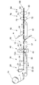
図2には、本発明の発熱体又は発熱具の製造に好ましく用いられる装置の一例が示されている。この装置は、塗料の塗工部20、電解質添加部30、第1裁断部40、リピッチ部50、被覆部60、封止部70及び第2裁断部80を備えている。
FIG. 2 shows an example of an apparatus preferably used for manufacturing the heating element or heating tool of the present invention. The apparatus includes a
塗工部20はダイコータ21を備えている。また、ダイコータ21のダイリップに対向し、かつ矢印方向に周回するワイヤメッシュの無端ベルト22も備えている。更に、無端ベルト23を挟んでダイコータ21のダイリップに対向してサクションボックス23も備えている。基材シートの原反ロール1Aから繰り出された連続長尺物からなる基材シート1は、無端ベルト22によって搬送され、その一方の面に、ダイコータ21によって、塗料が塗工され、該一面に塗料層が形成される。無端ベルト22による基材シート1の搬送に際してはサクションボックス23を作動させ、搬送を安定化させるとともに、塗料中の水を吸引して、基材シート1に吸収保持される水の量を調整することができる。塗料の塗工によって、塗料中の水が基材シート1に吸収されるので、塗料層の含水率は、塗料中の含水率よりも低下する。その結果、塗料層の流動性が低下する。
The
電解質添加部30は、電解質水溶液を滴下するノズル31を備えている。また、滴下ノズル31の開口部に対向し、かつ矢印方向に周回するワイヤメッシュの無端ベルト22も備えている。更に、無端ベルト22を挟んで滴下ノズル31の開口部に対向してサクションボックス33も備えている。塗工後の基材シートは、無端ベルト22によって、塗工部20から電解質添加部30に搬送され、その基材シートの塗工面に向かって、滴下ノズル31のノズル孔から電解質水溶液が滴下され、発熱層が形成される。電解質添加部30における基材シート1の搬送に際しては、サクションボックス33を作動させ、搬送を安定化させることもできる。塗工後の電解質水溶液の添加によって、発熱層中に発熱に好適な電解質の濃度を確保することができるとともに、電解質水溶液は、塗料層と基材シート1に含まれる水分によって、濃度が希釈されながら、基材シート1に吸収保持され、発熱層(塗料層)の水分率および電解質濃度が好適になる。また、電解質水溶液の散布時のサクションボックスの吸引により基材シート内部まで電解質水溶液の浸透が向上する。
The
このようにして連続長尺物からなる発熱体10Aが形成されたら、該発熱体10Aを第1裁断部40において、幅方向にわたって裁断する。第1裁断部40は、周面にカッター刃41を有するロータリーダイカッター42とアンビルロール43とを備えている。発熱体10Aが両部材間を通過することで裁断が行なわれ、それによって毎葉の発熱体10が得られる。
When the
連続長尺物からなる発熱体10Aの裁断は、発熱体10Aの幅方向に延びるように行なわれればよく、例えば発熱体10Aの幅方向にわたって直線的に行なうことができる。あるいは、裁断線が曲線を描くように裁断を行なうことができる。いずれの場合であっても、裁断によってトリムが発生しないような裁断パターンを採用することが好ましい。
The
毎葉となった発熱体10はリピッチ部50において搬送方向の前後におけるピッチが変更され、前後隣り合う発熱体10間が所定の距離を置いて再配置される。このようなリピッチの機構としては従来公知のものを特に制限なく用いることができる。
In the
リピッチされた発熱体10は、被覆部60に搬送され、連続長尺物からなる第1の被覆シート4と、同じく連続長尺物からなる第2の被覆シート5によってその全体が被覆される。第1の被覆シート4は、発熱体10における発熱層の形成されている側を被覆し、第2の被覆シート5は、発熱体10における発熱層が形成されていない側を被覆する。この被覆状態を保ちつつ、発熱体10は、被覆部60の備える無端ベルト61により封止部70に導入される。封止部70は、周面にシール凸部72を有する第1のロール71と、同じく周面にシール凸部72を有する第2のロール73とを備えている。両ロール71,73は、その軸方向が平行になるように、かつ各ロール71,73のシールバー72,72が互いに当接するか、又は両者間に所定のクリアランスが生じるような位置関係で配置されている。封止部70においては、発熱体10の前後左右から延出している第1及び第2の被覆シート4,5の延出部が、ヒートシールによって接合される。この接合は、発熱体10を取り囲む連続した気密の接合であるか、又は発熱体10を取り囲む不連続の接合である。
The
このようにして、複数の発熱具が一方向に連結された状態の連続長尺物が得られる。この連続長尺物を第2裁断部80において、その幅方向にわたって裁断する。第2裁断部80は、ロータリーダイカッター82とアンビルロール83とを備えている。連続長尺物が両部材間を通過することで裁断が行なわれ、それによって目的とする発熱具100が得られる。裁断においては、先に述べた第1裁断部40における発熱体10Aの裁断線が例えば直線状である場合には、本裁断部80における裁断線も直線とすることが好ましい。また、第1裁断部40における発熱体10Aの裁断線が曲線である場合には、本裁断部80における裁断線もそれに倣った曲線とすることが好ましい。
In this manner, a continuous long object in which a plurality of heating tools are connected in one direction is obtained. The continuous long object is cut in the width direction in the
図3には、本発明の発熱体又は発熱具の製造に好ましく用いられる装置の他の例が示されている。図3に示す装置は、リピッチ部50の配置位置が異なる点、及び電解質添加部30にサクションボックスが配置されていない点以外は、図2に示す装置と同様の構成を有している。すなわち、図2の装置は、電解質添加部30とリピッチ部50との間に第1裁断部40が配置されているのに対して、図3の装置は、塗工部20と電解質添加部30との間に第1裁断部40が配置されている。また、図3の装置においては、電解質添加部30には、基材シートの非塗工面側からの吸引を行うサクションボックス等の吸引手段が配置されていない。これら以外、図3の装置は、図2の装置と同様の構成を有している。
FIG. 3 shows another example of an apparatus preferably used for manufacturing the heating element or heating tool of the present invention. The apparatus shown in FIG. 3 has the same configuration as the apparatus shown in FIG. 2 except that the arrangement position of the
以下、実施例により本発明を更に詳細に説明する。しかしながら本発明の範囲は、かかる実施例に制限されない。特に断らない限り、「%」及び「部」はそれぞれ「質量%」及び「質量部」を意味する。 Hereinafter, the present invention will be described in more detail with reference to examples. However, the scope of the present invention is not limited to such examples. Unless otherwise specified, “%” and “part” mean “% by mass” and “part by mass”, respectively.
〔実施例1〕
(1)塗料及び電解質水溶液の調製
塗料としては、被酸化性金属(鉄粉 平均粒径45μm)100質量部、反応促進剤(活性炭 平均粒径42μm)8質量部、増粘剤(グアガム)0.2質量部、界面活性剤(ポリカルボン酸型高分子界面活性剤)0.2質量部、水60質量部が配合されているものを用いた。得られた塗料の粘度は6,500mPa・sであった。粘度の測定は、B型粘度計の4号ローターを使用し、23度50%RHの環境で行なった。
また、電解質水溶液として、濃度5%の塩化ナトリウム水溶液を調製した。
[Example 1]
(1) Preparation of paint and aqueous electrolyte solution As paint, 100 parts by mass of oxidizable metal (iron powder average particle size 45 μm), 8 parts by mass of reaction accelerator (activated carbon
A sodium chloride aqueous solution having a concentration of 5% was prepared as an aqueous electrolyte solution.
(2)基材シートの準備
基材シートとして図1に示すものを用いた。この基材シート1は、特開平8−246395号公報に記載の方法に従い製造した。この基材シート1は、ポリアクリル酸ナトリウム系の高吸収性ポリマーの粒子12が、基材シート1の厚み方向略中央域に主として存在しており、かつ基材シート1の表面には該粒子12が実質的に存在していない構造を有する1枚(ワンプライ)のものである。基材シート1は、高吸収性ポリマーの粒子12の存在部位を挟んで表裏に親水性の架橋嵩高セルロース繊維11aの層11,13を有している。架橋嵩高セルロース繊維11aは、その繊維粗度が0.22mg/mであり、繊維長さの平均値は2.5mmであった。架橋嵩高セルロース繊維11aの層11,13は、更に針葉樹晒クラフトパルプ、紙力増強剤(PVA)を含んでいる。また、高吸収性ポリマーは平均粒径340μmのものを使用した。層11の坪量は30g/m2であり、層13の坪量は20g/m2であった。高吸収性ポリマーの粒子12の坪量は30g/m2であった。したがって、基材シート1の坪量は80g/m2であった。
(2) Preparation of substrate sheet The substrate sheet shown in FIG. 1 was used. This
(3)発熱体及び発熱具の製造
前記の塗料を、連続長尺物からなる前記基材シートの一方の面に連続塗工した。塗料の塗工坪量は1,150g/m2とした。塗工の際には、基材シートの他方の面側から吸引を行った。但し、塗料中の水が、基材シートの非塗工面側から抜けるようなことはなかった。
次いで、連続長尺物からなる基材シートを幅方向に亘って裁断した後、切断された基材シートの塗料が塗工された面(塗工面)に向かって、滴下ノズルから電解質水溶液を滴下して発熱体10を得た。電解質水溶液を添加する際には、基材シートの非塗工面側からの吸引を行わなかった。また、電解質水溶液の散布坪量は80g/m2とした。
切断された基材シートは、50mm×50mmの矩形のものであった。
(3) Production of heating element and heating tool The coating material was continuously applied to one surface of the base sheet made of a continuous long article. The coating basis weight of the paint was 1,150 g / m 2 . During coating, suction was performed from the other side of the base sheet. However, water in the paint did not escape from the non-coated surface side of the base sheet.
Next, after cutting the substrate sheet made of continuous long material across the width direction, the electrolyte aqueous solution is dropped from the dropping nozzle toward the surface (coated surface) of the cut substrate sheet coated Thus, the
The cut base sheet was a 50 mm × 50 mm rectangle.
得られた発熱体10を、第1の被覆シート4と第2の被覆シート5によってその全体を被覆した。このとき、第1の被覆シート4によって、発熱体10における発熱層の形成されている側を被覆し、第2の被覆シート5によって、発熱体10における発熱層が形成されていない側を被覆した。次いで、発熱体10の前後左右から延出している第1及び第2の被覆シート4,5の延出部を、ヒートシールによって接合した。この接合は、発熱体10を取り囲む連続した気密の接合とした。シール幅は5mmとした。
The obtained
第1の被覆シート4としては、坪量が50g/m2、通気度が2,500s/(100ml・6.42cm2)であるポリエチレンの多孔性シートを用いた。第2の被覆シート5としては、坪量が30g/m2、ポリエチレンフィルムからなる非通気シートを用いた。また、各被覆シート4,5は、65mm×65mmの矩形のものであった。
As the
前述の方法より各含水率を測定した結果、塗工後、電解質水溶液添加前の塗料層を有するシート10A’の含水率は28%(塗料層含む)であり、電解質水溶液添加後、第1の被覆シート4による被覆前の発熱体10の含水率は32%であり、該発熱体10の発熱層の含水率は8%であった。
As a result of measuring each water content by the above-mentioned method, the water content of the
また、得られた発熱体10について、JIS S4100 使い捨てカイロ温度特性測定用温熱装置に準拠した試験法で温度測定を行った。得られた発熱具100を、坪量100g/m2のニードルパンチ不織布製の袋に挿入し、これを40℃の恒温槽の上に置き温度特性を評価した。この袋は、ニードルパンチ不織布の三方をシールすることで袋状に形成したものである。温度計は発熱具100と恒温槽表面との間に配置する。発熱具100は、発熱層が形成された側が上方(温度計とは逆の方向)を向くように載置した。その結果、測定開始から10分後に最高温度57℃となった。
Moreover, about the obtained
1 基材シート
10 発熱体
11 親水性繊維の層
12 高吸収性ポリマーの粒子
13 親水性繊維の層
100 発熱具
DESCRIPTION OF
Claims (5)
前記基材シートの一面に、前記電解質を含まず前記被酸化性金属の粒子を含む塗料を塗工する塗工工程、及び前記塗料が塗工された前記基材シートに、前記電解質を含む電解質水溶液を添加する電解質添加工程を備える発熱体の製造方法。 A method for producing a heating element, wherein a layer of a heat generating composition containing particles of an oxidizable metal, an electrolyte and water is provided on a base sheet made of a fiber sheet containing particles of a superabsorbent polymer and a fiber material. ,
An application step of applying a paint containing particles of the oxidizable metal not containing the electrolyte on one surface of the base material sheet, and an electrolyte containing the electrolyte on the base material sheet coated with the paint The manufacturing method of a heat generating body provided with the electrolyte addition process which adds aqueous solution.
前記発熱体製造工程では、前記発熱組成物の層が流動性を有しない発熱体を製造し、 前記包囲工程では、その状態の発熱体を、前記包材によって包囲して発熱具とする、発熱具の製造方法。 Includes an enclosure step of enclosing the heating element manufacturing process for manufacturing a heating element by the manufacturing method of the heating element according to any one of claims 1-4, and a whole of the resulting heating element packaging material,
In the heating element manufacturing step, a heating element in which the layer of the heating composition does not have fluidity is manufactured, and in the surrounding step, the heating element in that state is surrounded by the packaging material to form a heating tool. Manufacturing method of the tool.
Priority Applications (6)
| Application Number | Priority Date | Filing Date | Title |
|---|---|---|---|
| JP2010140014A JP5620161B2 (en) | 2010-06-18 | 2010-06-18 | Manufacturing method of heating element |
| CN201180030173.2A CN102946832B (en) | 2010-06-18 | 2011-06-16 | Heating element |
| US13/704,914 US9709260B2 (en) | 2010-06-18 | 2011-06-16 | Heat generating device |
| PCT/JP2011/063853 WO2011158919A1 (en) | 2010-06-18 | 2011-06-16 | Heating appliance |
| EP11795821.5A EP2583643B1 (en) | 2010-06-18 | 2011-06-16 | Heating appliance |
| CN201510414166.2A CN105105911B (en) | 2010-06-18 | 2011-06-16 | The manufacturing method of heater |
Applications Claiming Priority (1)
| Application Number | Priority Date | Filing Date | Title |
|---|---|---|---|
| JP2010140014A JP5620161B2 (en) | 2010-06-18 | 2010-06-18 | Manufacturing method of heating element |
Publications (3)
| Publication Number | Publication Date |
|---|---|
| JP2012000344A JP2012000344A (en) | 2012-01-05 |
| JP2012000344A5 JP2012000344A5 (en) | 2013-05-02 |
| JP5620161B2 true JP5620161B2 (en) | 2014-11-05 |
Family
ID=45533019
Family Applications (1)
| Application Number | Title | Priority Date | Filing Date |
|---|---|---|---|
| JP2010140014A Active JP5620161B2 (en) | 2010-06-18 | 2010-06-18 | Manufacturing method of heating element |
Country Status (1)
| Country | Link |
|---|---|
| JP (1) | JP5620161B2 (en) |
Families Citing this family (3)
| Publication number | Priority date | Publication date | Assignee | Title |
|---|---|---|---|---|
| JP6008587B2 (en) * | 2012-05-29 | 2016-10-19 | 花王株式会社 | Heating equipment |
| JP6120327B2 (en) * | 2013-08-26 | 2017-04-26 | 花王株式会社 | Manufacturing method of laminate |
| JP6653307B2 (en) | 2016-11-25 | 2020-02-26 | 花王株式会社 | Product manufacturing method and product manufacturing apparatus |
Family Cites Families (3)
| Publication number | Priority date | Publication date | Assignee | Title |
|---|---|---|---|---|
| CN1212814C (en) * | 1996-07-02 | 2005-08-03 | 日本巴伊欧尼克斯股份有限公司 | Sheet-shaped heating element and method for manufacturing same |
| JP4155791B2 (en) * | 2002-10-23 | 2008-09-24 | 花王株式会社 | Method for producing exothermic molded body |
| JP2007185396A (en) * | 2006-01-13 | 2007-07-26 | Mycoal Products Corp | Method for producing exothermic body, method for folding exothermic body, and manufacturing installation |
-
2010
- 2010-06-18 JP JP2010140014A patent/JP5620161B2/en active Active
Also Published As
| Publication number | Publication date |
|---|---|
| JP2012000344A (en) | 2012-01-05 |
Similar Documents
| Publication | Publication Date | Title |
|---|---|---|
| WO2011158919A1 (en) | Heating appliance | |
| TWI504388B (en) | Steam heating device | |
| TWI550079B (en) | Heat generation body and heat generation device | |
| RU2696129C1 (en) | Heating device and method of its production | |
| JP2014012829A (en) | Heating body, and warmer containing the same | |
| JP5620161B2 (en) | Manufacturing method of heating element | |
| JP5620162B2 (en) | Manufacturing method of heating element | |
| JP6715104B2 (en) | Heating equipment | |
| JP5894747B2 (en) | Heating tool | |
| JP5860279B2 (en) | Manufacturing method of heating tool | |
| CN108135735A (en) | Vapor generates body and warm utensil | |
| JP5894761B2 (en) | Manufacturing method of heating element and heating element | |
| JP5886028B2 (en) | Heating equipment | |
| JP4841363B2 (en) | Steam heating equipment | |
| WO2017014271A1 (en) | Heating tool | |
| JP6383235B2 (en) | Manufacturing method of heating tool | |
| JP5840554B2 (en) | Heating equipment | |
| JP5894783B2 (en) | Heating equipment | |
| JP5800589B2 (en) | Manufacturing method of heating element | |
| WO2020148966A1 (en) | Heating tool | |
| JP2023070553A (en) | Heating element production method | |
| KR101060632B1 (en) | Portable thermal sheet with thermal unit | |
| TW202114605A (en) | Heating instrument | |
| JP2016116806A (en) | Heating element |
Legal Events
| Date | Code | Title | Description |
|---|---|---|---|
| A521 | Request for written amendment filed |
Free format text: JAPANESE INTERMEDIATE CODE: A523 Effective date: 20130315 |
|
| A621 | Written request for application examination |
Free format text: JAPANESE INTERMEDIATE CODE: A621 Effective date: 20130315 |
|
| A131 | Notification of reasons for refusal |
Free format text: JAPANESE INTERMEDIATE CODE: A131 Effective date: 20140304 |
|
| A521 | Request for written amendment filed |
Free format text: JAPANESE INTERMEDIATE CODE: A523 Effective date: 20140425 |
|
| TRDD | Decision of grant or rejection written | ||
| A01 | Written decision to grant a patent or to grant a registration (utility model) |
Free format text: JAPANESE INTERMEDIATE CODE: A01 Effective date: 20140909 |
|
| A61 | First payment of annual fees (during grant procedure) |
Free format text: JAPANESE INTERMEDIATE CODE: A61 Effective date: 20140918 |
|
| R151 | Written notification of patent or utility model registration |
Ref document number: 5620161 Country of ref document: JP Free format text: JAPANESE INTERMEDIATE CODE: R151 |
|
| R250 | Receipt of annual fees |
Free format text: JAPANESE INTERMEDIATE CODE: R250 |
|
| R250 | Receipt of annual fees |
Free format text: JAPANESE INTERMEDIATE CODE: R250 |
|
| R250 | Receipt of annual fees |
Free format text: JAPANESE INTERMEDIATE CODE: R250 |
|
| R250 | Receipt of annual fees |
Free format text: JAPANESE INTERMEDIATE CODE: R250 |
|
| R250 | Receipt of annual fees |
Free format text: JAPANESE INTERMEDIATE CODE: R250 |
|
| R250 | Receipt of annual fees |
Free format text: JAPANESE INTERMEDIATE CODE: R250 |
|
| R250 | Receipt of annual fees |
Free format text: JAPANESE INTERMEDIATE CODE: R250 |