WO2020148851A1 - 送受電管理装置及びプログラム - Google Patents
送受電管理装置及びプログラム Download PDFInfo
- Publication number
- WO2020148851A1 WO2020148851A1 PCT/JP2019/001212 JP2019001212W WO2020148851A1 WO 2020148851 A1 WO2020148851 A1 WO 2020148851A1 JP 2019001212 W JP2019001212 W JP 2019001212W WO 2020148851 A1 WO2020148851 A1 WO 2020148851A1
- Authority
- WO
- WIPO (PCT)
- Prior art keywords
- vehicle
- user
- power transmission
- reception
- control unit
- Prior art date
- Legal status (The legal status is an assumption and is not a legal conclusion. Google has not performed a legal analysis and makes no representation as to the accuracy of the status listed.)
- Ceased
Links
Images




Classifications
-
- G—PHYSICS
- G06—COMPUTING OR CALCULATING; COUNTING
- G06Q—INFORMATION AND COMMUNICATION TECHNOLOGY [ICT] SPECIALLY ADAPTED FOR ADMINISTRATIVE, COMMERCIAL, FINANCIAL, MANAGERIAL OR SUPERVISORY PURPOSES; SYSTEMS OR METHODS SPECIALLY ADAPTED FOR ADMINISTRATIVE, COMMERCIAL, FINANCIAL, MANAGERIAL OR SUPERVISORY PURPOSES, NOT OTHERWISE PROVIDED FOR
- G06Q10/00—Administration; Management
- G06Q10/10—Office automation; Time management
- G06Q10/109—Time management, e.g. calendars, reminders, meetings or time accounting
- G06Q10/1093—Calendar-based scheduling for persons or groups
-
- B—PERFORMING OPERATIONS; TRANSPORTING
- B60—VEHICLES IN GENERAL
- B60L—PROPULSION OF ELECTRICALLY-PROPELLED VEHICLES; SUPPLYING ELECTRIC POWER FOR AUXILIARY EQUIPMENT OF ELECTRICALLY-PROPELLED VEHICLES; ELECTRODYNAMIC BRAKE SYSTEMS FOR VEHICLES IN GENERAL; MAGNETIC SUSPENSION OR LEVITATION FOR VEHICLES; MONITORING OPERATING VARIABLES OF ELECTRICALLY-PROPELLED VEHICLES; ELECTRIC SAFETY DEVICES FOR ELECTRICALLY-PROPELLED VEHICLES
- B60L53/00—Methods of charging batteries, specially adapted for electric vehicles; Charging stations or on-board charging equipment therefor; Exchange of energy storage elements in electric vehicles
- B60L53/10—Methods of charging batteries, specially adapted for electric vehicles; Charging stations or on-board charging equipment therefor; Exchange of energy storage elements in electric vehicles characterised by the energy transfer between the charging station and the vehicle
- B60L53/14—Conductive energy transfer
-
- B—PERFORMING OPERATIONS; TRANSPORTING
- B60—VEHICLES IN GENERAL
- B60L—PROPULSION OF ELECTRICALLY-PROPELLED VEHICLES; SUPPLYING ELECTRIC POWER FOR AUXILIARY EQUIPMENT OF ELECTRICALLY-PROPELLED VEHICLES; ELECTRODYNAMIC BRAKE SYSTEMS FOR VEHICLES IN GENERAL; MAGNETIC SUSPENSION OR LEVITATION FOR VEHICLES; MONITORING OPERATING VARIABLES OF ELECTRICALLY-PROPELLED VEHICLES; ELECTRIC SAFETY DEVICES FOR ELECTRICALLY-PROPELLED VEHICLES
- B60L53/00—Methods of charging batteries, specially adapted for electric vehicles; Charging stations or on-board charging equipment therefor; Exchange of energy storage elements in electric vehicles
- B60L53/10—Methods of charging batteries, specially adapted for electric vehicles; Charging stations or on-board charging equipment therefor; Exchange of energy storage elements in electric vehicles characterised by the energy transfer between the charging station and the vehicle
- B60L53/14—Conductive energy transfer
- B60L53/18—Cables specially adapted for charging electric vehicles
-
- B—PERFORMING OPERATIONS; TRANSPORTING
- B60—VEHICLES IN GENERAL
- B60L—PROPULSION OF ELECTRICALLY-PROPELLED VEHICLES; SUPPLYING ELECTRIC POWER FOR AUXILIARY EQUIPMENT OF ELECTRICALLY-PROPELLED VEHICLES; ELECTRODYNAMIC BRAKE SYSTEMS FOR VEHICLES IN GENERAL; MAGNETIC SUSPENSION OR LEVITATION FOR VEHICLES; MONITORING OPERATING VARIABLES OF ELECTRICALLY-PROPELLED VEHICLES; ELECTRIC SAFETY DEVICES FOR ELECTRICALLY-PROPELLED VEHICLES
- B60L53/00—Methods of charging batteries, specially adapted for electric vehicles; Charging stations or on-board charging equipment therefor; Exchange of energy storage elements in electric vehicles
- B60L53/60—Monitoring or controlling charging stations
- B60L53/62—Monitoring or controlling charging stations in response to charging parameters, e.g. current, voltage or electrical charge
-
- B—PERFORMING OPERATIONS; TRANSPORTING
- B60—VEHICLES IN GENERAL
- B60L—PROPULSION OF ELECTRICALLY-PROPELLED VEHICLES; SUPPLYING ELECTRIC POWER FOR AUXILIARY EQUIPMENT OF ELECTRICALLY-PROPELLED VEHICLES; ELECTRODYNAMIC BRAKE SYSTEMS FOR VEHICLES IN GENERAL; MAGNETIC SUSPENSION OR LEVITATION FOR VEHICLES; MONITORING OPERATING VARIABLES OF ELECTRICALLY-PROPELLED VEHICLES; ELECTRIC SAFETY DEVICES FOR ELECTRICALLY-PROPELLED VEHICLES
- B60L53/00—Methods of charging batteries, specially adapted for electric vehicles; Charging stations or on-board charging equipment therefor; Exchange of energy storage elements in electric vehicles
- B60L53/60—Monitoring or controlling charging stations
- B60L53/63—Monitoring or controlling charging stations in response to network capacity
-
- B—PERFORMING OPERATIONS; TRANSPORTING
- B60—VEHICLES IN GENERAL
- B60L—PROPULSION OF ELECTRICALLY-PROPELLED VEHICLES; SUPPLYING ELECTRIC POWER FOR AUXILIARY EQUIPMENT OF ELECTRICALLY-PROPELLED VEHICLES; ELECTRODYNAMIC BRAKE SYSTEMS FOR VEHICLES IN GENERAL; MAGNETIC SUSPENSION OR LEVITATION FOR VEHICLES; MONITORING OPERATING VARIABLES OF ELECTRICALLY-PROPELLED VEHICLES; ELECTRIC SAFETY DEVICES FOR ELECTRICALLY-PROPELLED VEHICLES
- B60L53/00—Methods of charging batteries, specially adapted for electric vehicles; Charging stations or on-board charging equipment therefor; Exchange of energy storage elements in electric vehicles
- B60L53/60—Monitoring or controlling charging stations
- B60L53/68—Off-site monitoring or control, e.g. remote control
-
- B—PERFORMING OPERATIONS; TRANSPORTING
- B60—VEHICLES IN GENERAL
- B60L—PROPULSION OF ELECTRICALLY-PROPELLED VEHICLES; SUPPLYING ELECTRIC POWER FOR AUXILIARY EQUIPMENT OF ELECTRICALLY-PROPELLED VEHICLES; ELECTRODYNAMIC BRAKE SYSTEMS FOR VEHICLES IN GENERAL; MAGNETIC SUSPENSION OR LEVITATION FOR VEHICLES; MONITORING OPERATING VARIABLES OF ELECTRICALLY-PROPELLED VEHICLES; ELECTRIC SAFETY DEVICES FOR ELECTRICALLY-PROPELLED VEHICLES
- B60L55/00—Arrangements for supplying energy stored within a vehicle to a power network, i.e. vehicle-to-grid [V2G] arrangements
-
- G—PHYSICS
- G01—MEASURING; TESTING
- G01C—MEASURING DISTANCES, LEVELS OR BEARINGS; SURVEYING; NAVIGATION; GYROSCOPIC INSTRUMENTS; PHOTOGRAMMETRY OR VIDEOGRAMMETRY
- G01C21/00—Navigation; Navigational instruments not provided for in groups G01C1/00 - G01C19/00
- G01C21/26—Navigation; Navigational instruments not provided for in groups G01C1/00 - G01C19/00 specially adapted for navigation in a road network
- G01C21/28—Navigation; Navigational instruments not provided for in groups G01C1/00 - G01C19/00 specially adapted for navigation in a road network with correlation of data from several navigational instruments
-
- G—PHYSICS
- G01—MEASURING; TESTING
- G01C—MEASURING DISTANCES, LEVELS OR BEARINGS; SURVEYING; NAVIGATION; GYROSCOPIC INSTRUMENTS; PHOTOGRAMMETRY OR VIDEOGRAMMETRY
- G01C21/00—Navigation; Navigational instruments not provided for in groups G01C1/00 - G01C19/00
- G01C21/26—Navigation; Navigational instruments not provided for in groups G01C1/00 - G01C19/00 specially adapted for navigation in a road network
- G01C21/34—Route searching; Route guidance
- G01C21/3453—Special cost functions, i.e. other than distance or default speed limit of road segments
- G01C21/3469—Fuel consumption; Energy use; Emission aspects
-
- G—PHYSICS
- G01—MEASURING; TESTING
- G01C—MEASURING DISTANCES, LEVELS OR BEARINGS; SURVEYING; NAVIGATION; GYROSCOPIC INSTRUMENTS; PHOTOGRAMMETRY OR VIDEOGRAMMETRY
- G01C21/00—Navigation; Navigational instruments not provided for in groups G01C1/00 - G01C19/00
- G01C21/26—Navigation; Navigational instruments not provided for in groups G01C1/00 - G01C19/00 specially adapted for navigation in a road network
- G01C21/34—Route searching; Route guidance
- G01C21/36—Input/output arrangements for on-board computers
- G01C21/3605—Destination input or retrieval
- G01C21/3617—Destination input or retrieval using user history, behaviour, conditions or preferences, e.g. predicted or inferred from previous use or current movement
-
- G—PHYSICS
- G01—MEASURING; TESTING
- G01C—MEASURING DISTANCES, LEVELS OR BEARINGS; SURVEYING; NAVIGATION; GYROSCOPIC INSTRUMENTS; PHOTOGRAMMETRY OR VIDEOGRAMMETRY
- G01C21/00—Navigation; Navigational instruments not provided for in groups G01C1/00 - G01C19/00
- G01C21/26—Navigation; Navigational instruments not provided for in groups G01C1/00 - G01C19/00 specially adapted for navigation in a road network
- G01C21/34—Route searching; Route guidance
- G01C21/36—Input/output arrangements for on-board computers
- G01C21/3697—Output of additional, non-guidance related information, e.g. low fuel level
-
- G—PHYSICS
- G06—COMPUTING OR CALCULATING; COUNTING
- G06Q—INFORMATION AND COMMUNICATION TECHNOLOGY [ICT] SPECIALLY ADAPTED FOR ADMINISTRATIVE, COMMERCIAL, FINANCIAL, MANAGERIAL OR SUPERVISORY PURPOSES; SYSTEMS OR METHODS SPECIALLY ADAPTED FOR ADMINISTRATIVE, COMMERCIAL, FINANCIAL, MANAGERIAL OR SUPERVISORY PURPOSES, NOT OTHERWISE PROVIDED FOR
- G06Q10/00—Administration; Management
- G06Q10/06—Resources, workflows, human or project management; Enterprise or organisation planning; Enterprise or organisation modelling
- G06Q10/063—Operations research, analysis or management
- G06Q10/0631—Resource planning, allocation, distributing or scheduling for enterprises or organisations
- G06Q10/06312—Adjustment or analysis of established resource schedule, e.g. resource or task levelling, or dynamic rescheduling
-
- G—PHYSICS
- G06—COMPUTING OR CALCULATING; COUNTING
- G06Q—INFORMATION AND COMMUNICATION TECHNOLOGY [ICT] SPECIALLY ADAPTED FOR ADMINISTRATIVE, COMMERCIAL, FINANCIAL, MANAGERIAL OR SUPERVISORY PURPOSES; SYSTEMS OR METHODS SPECIALLY ADAPTED FOR ADMINISTRATIVE, COMMERCIAL, FINANCIAL, MANAGERIAL OR SUPERVISORY PURPOSES, NOT OTHERWISE PROVIDED FOR
- G06Q50/00—Information and communication technology [ICT] specially adapted for implementation of business processes of specific business sectors, e.g. utilities or tourism
- G06Q50/10—Services
-
- H—ELECTRICITY
- H02—GENERATION; CONVERSION OR DISTRIBUTION OF ELECTRIC POWER
- H02J—ELECTRIC POWER NETWORKS; CIRCUIT ARRANGEMENTS OR SYSTEMS FOR SUPPLYING OR DISTRIBUTING ELECTRIC POWER; SYSTEMS FOR STORING ELECTRIC ENERGY
- H02J3/00—Circuit arrangements for AC mains or AC distribution networks
- H02J3/28—Arrangements for balancing of the load in networks by storage of energy
- H02J3/32—Arrangements for balancing of the load in networks by storage of energy using batteries or super capacitors with converting means
-
- H—ELECTRICITY
- H02—GENERATION; CONVERSION OR DISTRIBUTION OF ELECTRIC POWER
- H02J—ELECTRIC POWER NETWORKS; CIRCUIT ARRANGEMENTS OR SYSTEMS FOR SUPPLYING OR DISTRIBUTING ELECTRIC POWER; SYSTEMS FOR STORING ELECTRIC ENERGY
- H02J7/00—Circuit arrangements for charging or discharging batteries or for supplying loads from batteries
-
- B—PERFORMING OPERATIONS; TRANSPORTING
- B60—VEHICLES IN GENERAL
- B60L—PROPULSION OF ELECTRICALLY-PROPELLED VEHICLES; SUPPLYING ELECTRIC POWER FOR AUXILIARY EQUIPMENT OF ELECTRICALLY-PROPELLED VEHICLES; ELECTRODYNAMIC BRAKE SYSTEMS FOR VEHICLES IN GENERAL; MAGNETIC SUSPENSION OR LEVITATION FOR VEHICLES; MONITORING OPERATING VARIABLES OF ELECTRICALLY-PROPELLED VEHICLES; ELECTRIC SAFETY DEVICES FOR ELECTRICALLY-PROPELLED VEHICLES
- B60L2240/00—Control parameters of input or output; Target parameters
- B60L2240/60—Navigation input
- B60L2240/62—Vehicle position
-
- B—PERFORMING OPERATIONS; TRANSPORTING
- B60—VEHICLES IN GENERAL
- B60L—PROPULSION OF ELECTRICALLY-PROPELLED VEHICLES; SUPPLYING ELECTRIC POWER FOR AUXILIARY EQUIPMENT OF ELECTRICALLY-PROPELLED VEHICLES; ELECTRODYNAMIC BRAKE SYSTEMS FOR VEHICLES IN GENERAL; MAGNETIC SUSPENSION OR LEVITATION FOR VEHICLES; MONITORING OPERATING VARIABLES OF ELECTRICALLY-PROPELLED VEHICLES; ELECTRIC SAFETY DEVICES FOR ELECTRICALLY-PROPELLED VEHICLES
- B60L2240/00—Control parameters of input or output; Target parameters
- B60L2240/80—Time limits
-
- B—PERFORMING OPERATIONS; TRANSPORTING
- B60—VEHICLES IN GENERAL
- B60L—PROPULSION OF ELECTRICALLY-PROPELLED VEHICLES; SUPPLYING ELECTRIC POWER FOR AUXILIARY EQUIPMENT OF ELECTRICALLY-PROPELLED VEHICLES; ELECTRODYNAMIC BRAKE SYSTEMS FOR VEHICLES IN GENERAL; MAGNETIC SUSPENSION OR LEVITATION FOR VEHICLES; MONITORING OPERATING VARIABLES OF ELECTRICALLY-PROPELLED VEHICLES; ELECTRIC SAFETY DEVICES FOR ELECTRICALLY-PROPELLED VEHICLES
- B60L2250/00—Driver interactions
- B60L2250/16—Driver interactions by display
-
- B—PERFORMING OPERATIONS; TRANSPORTING
- B60—VEHICLES IN GENERAL
- B60L—PROPULSION OF ELECTRICALLY-PROPELLED VEHICLES; SUPPLYING ELECTRIC POWER FOR AUXILIARY EQUIPMENT OF ELECTRICALLY-PROPELLED VEHICLES; ELECTRODYNAMIC BRAKE SYSTEMS FOR VEHICLES IN GENERAL; MAGNETIC SUSPENSION OR LEVITATION FOR VEHICLES; MONITORING OPERATING VARIABLES OF ELECTRICALLY-PROPELLED VEHICLES; ELECTRIC SAFETY DEVICES FOR ELECTRICALLY-PROPELLED VEHICLES
- B60L2260/00—Operating Modes
- B60L2260/40—Control modes
- B60L2260/46—Control modes by self learning
-
- B—PERFORMING OPERATIONS; TRANSPORTING
- B60—VEHICLES IN GENERAL
- B60L—PROPULSION OF ELECTRICALLY-PROPELLED VEHICLES; SUPPLYING ELECTRIC POWER FOR AUXILIARY EQUIPMENT OF ELECTRICALLY-PROPELLED VEHICLES; ELECTRODYNAMIC BRAKE SYSTEMS FOR VEHICLES IN GENERAL; MAGNETIC SUSPENSION OR LEVITATION FOR VEHICLES; MONITORING OPERATING VARIABLES OF ELECTRICALLY-PROPELLED VEHICLES; ELECTRIC SAFETY DEVICES FOR ELECTRICALLY-PROPELLED VEHICLES
- B60L53/00—Methods of charging batteries, specially adapted for electric vehicles; Charging stations or on-board charging equipment therefor; Exchange of energy storage elements in electric vehicles
- B60L53/60—Monitoring or controlling charging stations
- B60L53/66—Data transfer between charging stations and vehicles
- B60L53/665—Methods related to measuring, billing or payment
-
- G—PHYSICS
- G06—COMPUTING OR CALCULATING; COUNTING
- G06Q—INFORMATION AND COMMUNICATION TECHNOLOGY [ICT] SPECIALLY ADAPTED FOR ADMINISTRATIVE, COMMERCIAL, FINANCIAL, MANAGERIAL OR SUPERVISORY PURPOSES; SYSTEMS OR METHODS SPECIALLY ADAPTED FOR ADMINISTRATIVE, COMMERCIAL, FINANCIAL, MANAGERIAL OR SUPERVISORY PURPOSES, NOT OTHERWISE PROVIDED FOR
- G06Q30/00—Commerce
- G06Q30/02—Marketing; Price estimation or determination; Fundraising
- G06Q30/0207—Discounts or incentives, e.g. coupons or rebates
- G06Q30/0226—Incentive systems for frequent usage, e.g. frequent flyer miles programs or point systems
-
- G—PHYSICS
- G06—COMPUTING OR CALCULATING; COUNTING
- G06Q—INFORMATION AND COMMUNICATION TECHNOLOGY [ICT] SPECIALLY ADAPTED FOR ADMINISTRATIVE, COMMERCIAL, FINANCIAL, MANAGERIAL OR SUPERVISORY PURPOSES; SYSTEMS OR METHODS SPECIALLY ADAPTED FOR ADMINISTRATIVE, COMMERCIAL, FINANCIAL, MANAGERIAL OR SUPERVISORY PURPOSES, NOT OTHERWISE PROVIDED FOR
- G06Q50/00—Information and communication technology [ICT] specially adapted for implementation of business processes of specific business sectors, e.g. utilities or tourism
- G06Q50/06—Energy or water supply
-
- Y—GENERAL TAGGING OF NEW TECHNOLOGICAL DEVELOPMENTS; GENERAL TAGGING OF CROSS-SECTIONAL TECHNOLOGIES SPANNING OVER SEVERAL SECTIONS OF THE IPC; TECHNICAL SUBJECTS COVERED BY FORMER USPC CROSS-REFERENCE ART COLLECTIONS [XRACs] AND DIGESTS
- Y02—TECHNOLOGIES OR APPLICATIONS FOR MITIGATION OR ADAPTATION AGAINST CLIMATE CHANGE
- Y02E—REDUCTION OF GREENHOUSE GAS [GHG] EMISSIONS, RELATED TO ENERGY GENERATION, TRANSMISSION OR DISTRIBUTION
- Y02E60/00—Enabling technologies; Technologies with a potential or indirect contribution to GHG emissions mitigation
-
- Y—GENERAL TAGGING OF NEW TECHNOLOGICAL DEVELOPMENTS; GENERAL TAGGING OF CROSS-SECTIONAL TECHNOLOGIES SPANNING OVER SEVERAL SECTIONS OF THE IPC; TECHNICAL SUBJECTS COVERED BY FORMER USPC CROSS-REFERENCE ART COLLECTIONS [XRACs] AND DIGESTS
- Y02—TECHNOLOGIES OR APPLICATIONS FOR MITIGATION OR ADAPTATION AGAINST CLIMATE CHANGE
- Y02T—CLIMATE CHANGE MITIGATION TECHNOLOGIES RELATED TO TRANSPORTATION
- Y02T10/00—Road transport of goods or passengers
- Y02T10/60—Other road transportation technologies with climate change mitigation effect
- Y02T10/70—Energy storage systems for electromobility, e.g. batteries
-
- Y—GENERAL TAGGING OF NEW TECHNOLOGICAL DEVELOPMENTS; GENERAL TAGGING OF CROSS-SECTIONAL TECHNOLOGIES SPANNING OVER SEVERAL SECTIONS OF THE IPC; TECHNICAL SUBJECTS COVERED BY FORMER USPC CROSS-REFERENCE ART COLLECTIONS [XRACs] AND DIGESTS
- Y02—TECHNOLOGIES OR APPLICATIONS FOR MITIGATION OR ADAPTATION AGAINST CLIMATE CHANGE
- Y02T—CLIMATE CHANGE MITIGATION TECHNOLOGIES RELATED TO TRANSPORTATION
- Y02T10/00—Road transport of goods or passengers
- Y02T10/60—Other road transportation technologies with climate change mitigation effect
- Y02T10/7072—Electromobility specific charging systems or methods for batteries, ultracapacitors, supercapacitors or double-layer capacitors
-
- Y—GENERAL TAGGING OF NEW TECHNOLOGICAL DEVELOPMENTS; GENERAL TAGGING OF CROSS-SECTIONAL TECHNOLOGIES SPANNING OVER SEVERAL SECTIONS OF THE IPC; TECHNICAL SUBJECTS COVERED BY FORMER USPC CROSS-REFERENCE ART COLLECTIONS [XRACs] AND DIGESTS
- Y02—TECHNOLOGIES OR APPLICATIONS FOR MITIGATION OR ADAPTATION AGAINST CLIMATE CHANGE
- Y02T—CLIMATE CHANGE MITIGATION TECHNOLOGIES RELATED TO TRANSPORTATION
- Y02T10/00—Road transport of goods or passengers
- Y02T10/60—Other road transportation technologies with climate change mitigation effect
- Y02T10/72—Electric energy management in electromobility
-
- Y—GENERAL TAGGING OF NEW TECHNOLOGICAL DEVELOPMENTS; GENERAL TAGGING OF CROSS-SECTIONAL TECHNOLOGIES SPANNING OVER SEVERAL SECTIONS OF THE IPC; TECHNICAL SUBJECTS COVERED BY FORMER USPC CROSS-REFERENCE ART COLLECTIONS [XRACs] AND DIGESTS
- Y02—TECHNOLOGIES OR APPLICATIONS FOR MITIGATION OR ADAPTATION AGAINST CLIMATE CHANGE
- Y02T—CLIMATE CHANGE MITIGATION TECHNOLOGIES RELATED TO TRANSPORTATION
- Y02T90/00—Enabling technologies or technologies with a potential or indirect contribution to GHG emissions mitigation
- Y02T90/10—Technologies relating to charging of electric vehicles
- Y02T90/12—Electric charging stations
-
- Y—GENERAL TAGGING OF NEW TECHNOLOGICAL DEVELOPMENTS; GENERAL TAGGING OF CROSS-SECTIONAL TECHNOLOGIES SPANNING OVER SEVERAL SECTIONS OF THE IPC; TECHNICAL SUBJECTS COVERED BY FORMER USPC CROSS-REFERENCE ART COLLECTIONS [XRACs] AND DIGESTS
- Y02—TECHNOLOGIES OR APPLICATIONS FOR MITIGATION OR ADAPTATION AGAINST CLIMATE CHANGE
- Y02T—CLIMATE CHANGE MITIGATION TECHNOLOGIES RELATED TO TRANSPORTATION
- Y02T90/00—Enabling technologies or technologies with a potential or indirect contribution to GHG emissions mitigation
- Y02T90/10—Technologies relating to charging of electric vehicles
- Y02T90/14—Plug-in electric vehicles
-
- Y—GENERAL TAGGING OF NEW TECHNOLOGICAL DEVELOPMENTS; GENERAL TAGGING OF CROSS-SECTIONAL TECHNOLOGIES SPANNING OVER SEVERAL SECTIONS OF THE IPC; TECHNICAL SUBJECTS COVERED BY FORMER USPC CROSS-REFERENCE ART COLLECTIONS [XRACs] AND DIGESTS
- Y02—TECHNOLOGIES OR APPLICATIONS FOR MITIGATION OR ADAPTATION AGAINST CLIMATE CHANGE
- Y02T—CLIMATE CHANGE MITIGATION TECHNOLOGIES RELATED TO TRANSPORTATION
- Y02T90/00—Enabling technologies or technologies with a potential or indirect contribution to GHG emissions mitigation
- Y02T90/10—Technologies relating to charging of electric vehicles
- Y02T90/16—Information or communication technologies improving the operation of electric vehicles
-
- Y—GENERAL TAGGING OF NEW TECHNOLOGICAL DEVELOPMENTS; GENERAL TAGGING OF CROSS-SECTIONAL TECHNOLOGIES SPANNING OVER SEVERAL SECTIONS OF THE IPC; TECHNICAL SUBJECTS COVERED BY FORMER USPC CROSS-REFERENCE ART COLLECTIONS [XRACs] AND DIGESTS
- Y04—INFORMATION OR COMMUNICATION TECHNOLOGIES HAVING AN IMPACT ON OTHER TECHNOLOGY AREAS
- Y04S—SYSTEMS INTEGRATING TECHNOLOGIES RELATED TO POWER NETWORK OPERATION, COMMUNICATION OR INFORMATION TECHNOLOGIES FOR IMPROVING THE ELECTRICAL POWER GENERATION, TRANSMISSION, DISTRIBUTION, MANAGEMENT OR USAGE, i.e. SMART GRIDS
- Y04S10/00—Systems supporting electrical power generation, transmission or distribution
- Y04S10/12—Monitoring or controlling equipment for energy generation units, e.g. distributed energy generation [DER] or load-side generation
- Y04S10/126—Monitoring or controlling equipment for energy generation units, e.g. distributed energy generation [DER] or load-side generation the energy generation units being or involving electric vehicles [EV] or hybrid vehicles [HEV], i.e. power aggregation of EV or HEV, vehicle to grid arrangements [V2G]
-
- Y—GENERAL TAGGING OF NEW TECHNOLOGICAL DEVELOPMENTS; GENERAL TAGGING OF CROSS-SECTIONAL TECHNOLOGIES SPANNING OVER SEVERAL SECTIONS OF THE IPC; TECHNICAL SUBJECTS COVERED BY FORMER USPC CROSS-REFERENCE ART COLLECTIONS [XRACs] AND DIGESTS
- Y04—INFORMATION OR COMMUNICATION TECHNOLOGIES HAVING AN IMPACT ON OTHER TECHNOLOGY AREAS
- Y04S—SYSTEMS INTEGRATING TECHNOLOGIES RELATED TO POWER NETWORK OPERATION, COMMUNICATION OR INFORMATION TECHNOLOGIES FOR IMPROVING THE ELECTRICAL POWER GENERATION, TRANSMISSION, DISTRIBUTION, MANAGEMENT OR USAGE, i.e. SMART GRIDS
- Y04S50/00—Market activities related to the operation of systems integrating technologies related to power network operation or related to communication or information technologies
- Y04S50/14—Marketing, i.e. market research and analysis, surveying, promotions, advertising, buyer profiling, customer management or rewards
Definitions
- the present invention relates to a power transmission/reception management device and a program.
- Patent Document 1 Japanese Patent No. 5432292
- Patent Document 2 Japanese Unexamined Patent Publication No. 2017-028787
- a power transmission and reception management device includes a storage unit that stores information indicating a correspondence relationship between a vehicle including a driving power supply and a power network and a scheduled period during which power transmission/reception is possible.
- the power transmission/reception management device includes a notification control unit configured to perform a notification to a user associated with the vehicle when the vehicle is not enabled to transmit and receive power to and from the power grid at a predetermined time point before the scheduled period.
- the notification control unit is associated with the vehicle when the vehicle is not connected to a power transmission and reception facility for transmitting and receiving electric power between the vehicle and the power grid at a predetermined time point before the scheduled period. The user may be notified.
- the notification control unit may determine the time at which the user is notified based on the current position of the vehicle, the position of the power transmission/reception facility, and the scheduled period.
- the notification control unit may determine the time point at which the user is notified based on the current position of the vehicle, the history of vehicle position information, the position of the power transmission/reception facility, and the scheduled period.
- the notification control unit determines, based on a plurality of reference movement patterns specified from the history of vehicle position information, the current movement pattern of the vehicle, the position of the power transmitting and receiving equipment, and the scheduled period, the time at which the user is notified. You may decide.
- the notification control unit notifies the user at an earlier time when there is no reference movement pattern that matches the current movement pattern of the vehicle among the plurality of reference movement patterns and has the power transmission and reception equipment at the destination. You can let me do it in.
- the notification control unit specifies the reference movement pattern that matches the current movement pattern of the vehicle and has the power transmission/reception facility at the destination among the plurality of reference movement patterns, and determines the scheduled period and the specified reference movement pattern.
- the user may be notified when the difference from the estimated arrival time is shorter than a predetermined time difference.
- the notification control unit may determine a time point at which the user is notified based on the current position of the user.
- the notification control unit may determine the time point at which the user is notified based on the current position of the user, the current position of the vehicle, and the scheduled period.
- the notification control unit may cause the user to be notified when the vehicle is not connected to the power transmission/reception facility at a time point that is predetermined by the user before the scheduled period.
- the notification control unit may prioritize notification to users who are closer to the vehicle and the power transmission/reception facility when multiple users are associated with the vehicle.
- the notification control unit specifies one or more reference positions from the history of the position information of the vehicle, and when the current position of the vehicle does not exist within a predetermined range from the specified reference position, notifies the user earlier. May be done at a point in time.
- the power transmission/reception management device transmits/receives the vehicle at a predetermined time point before the scheduled period when the vehicle is not connected to the power transmission/reception facility for transmitting/receiving the electric power between the vehicle and the power grid.
- a connection request control unit that requests a person other than the user who can connect to the facility to connect the vehicle to the power transmitting and receiving facility may be provided.
- the power transmission/reception management device may further include a cancellation information acquisition unit that acquires, from the user, cancellation information indicating cancellation of the power transmission/reception schedule between the vehicle and the power grid during the scheduled period.
- the notification control unit acquires the cancellation information, the notification control unit may notify a user of another vehicle to perform power transmission/reception with the power grid during the scheduled period.
- the notification control unit causes the user to be notified before the scheduled period when the vehicle has not been enabled to transmit and receive power to and from the power grid when a predetermined time has elapsed since the user got off the vehicle. You can
- a program functions as the power transmission/reception management device.
- FIG. 1 schematically shows the basic configuration of a power transmission/reception system 100.
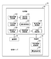
- 1 schematically shows the functional configuration of the management server 40.
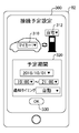
- An example of the screen 300 for setting the scheduled period for connecting the vehicle 30 to the charge/discharge equipment 20 is shown.
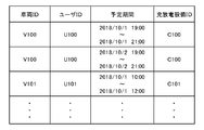
- An example of the schedule information is shown in a table format.
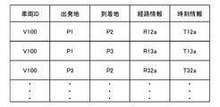
- An example of history information indicating the position history of the vehicle 30 is shown in a table format.
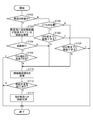
- FIG. 8 is a diagram for explaining a process of determining whether to transmit a connection confirmation notification based on history information. It is a flowchart which shows the process regarding transmission of a connection confirmation notification.
- the exchange when a user 80 other than the user of the vehicle 30 connects the vehicle 30 to the charge/discharge equipment 20 is schematically shown.
- 6 is a flowchart showing a process when a user 80 other than the user of the vehicle 30 connects the vehicle 30 to the charge/discharge equipment 20.
- 1 illustrates an example computer 2000 in which embodiments of the present invention may be implemented in
- FIG. 1 schematically shows the basic configuration of the power transmission/reception system 100.
- the power transmission/reception system 100 is, for example, a system in which a power aggregator performs V2G (Vehicle-to-Grid) in which electric power is exchanged between a vehicle and an electric power grid by using a battery included in the vehicle.
- Power transmission/reception system 100 has a function of promoting connection of a vehicle to the power grid.
- V2G means that the vehicle releases electric power to the electric power grid and/or that the vehicle receives electric power from the electric power grid.
- the power transmission/reception system 100 includes a plurality of vehicles including a vehicle 30a and a vehicle 30b, a stationary battery 14, a plurality of charging/discharging facilities 20, a management server 40, a power generation facility 12, a user terminal 82a, a user terminal 82b, and a user.
- a plurality of user terminals including the terminal 82c.
- the users 80a, 80b, and 80c are users of the power transmission/reception system 100.
- the user 80a is the user of the vehicle 30a
- the user 80b is the user of the vehicle 30b.
- the vehicle user may be any person who uses the vehicle, such as the vehicle owner or the owner's family.
- the user 80c is neither the user of the vehicle 30a nor the user of the vehicle 30b.
- the users 80a, 80b, and 80c may be collectively referred to as "user 80".
- the vehicle 30a includes a battery 32a.
- the vehicle 30b includes a battery 32b.
- the plurality of vehicles including the vehicle 30a and the vehicle 30b may be collectively referred to as "vehicle 30".
- a plurality of batteries including the battery 32a and the battery 32b may be collectively referred to as a "battery 32".
- the battery 32 is an example of a driving power source included in the vehicle 30.
- the driving power supply includes a power supply such as a fuel cell that consumes fuel to generate electric energy provided to the power source of the vehicle 30.
- the fuel may be hydrogen, hydrocarbon fuel such as gasoline, light oil and natural gas, alcohol fuel and the like.
- the driving power source may be any power source capable of producing electrical energy provided to the power source of vehicle 30.
- the vehicle 30 is an example of transportation equipment.
- the vehicle 30 is a vehicle including a power source driven by electric energy, such as an electric vehicle and a fuel cell vehicle (FCV).
- Electric vehicles include battery-powered electric vehicles (BEVs) and hybrid vehicles or plug-in hybrid electric vehicles (PHEVs) that include an internal combustion engine that provides at least some of the power.
- the vehicle 30 is an electric vehicle including a battery 32 as a driving power source.
- the battery is adopted as the driving power source
- discharging the battery corresponds to releasing energy from the driving power source
- charging the battery corresponds to storing energy in the driving power source.
- the remaining capacity of the battery corresponds to the amount of energy stored in the driving power source, such as the amount of electric power or the amount of electricity that can be supplied from the driving power source.
- the user terminal 82a is a communication terminal used by the user 80a.
- the user terminal 82b is a communication terminal used by the user 80b.
- the user terminal 82c is a communication terminal used by the user 80c.
- a plurality of user terminals including the user terminal 82a, the user terminal 82b, and the user terminal 82c may be collectively referred to as a "user terminal 82".
- the user terminal 82 may be, for example, a mobile terminal, a personal computer, a vehicle navigation device, or the like.
- Examples of the mobile terminal include mobile phones, smartphones, PDAs, tablets, notebook computers, laptop computers, wearable computers and the like.
- the management server 40 can communicate with the vehicle 30, the stationary battery 14, and the user terminal 82 through the communication network.
- the management server 40 can also communicate with the power trading server 50 via a communication network.
- the communication network may include a transmission path for wired communication or wireless communication.
- the communication network may include a communication network including the Internet, a P2P network, a dedicated line, a VPN, a power line communication line, a mobile phone line, and the like.
- the power grid 10 may include a power grid or a power grid, or a power grid grid.
- the vehicle 30, the stationary battery 14, the charging/discharging facility 20, and the power generation facility 12 are connected to the power grid 10.
- the charging/discharging facility 20, the stationary battery 14, and the power generation facility 12 can transfer power to and from the power grid 10.
- the power generation facility 12 is managed by a power company or the like.
- the charging/discharging facility 20 includes, for example, a charging/discharging device installed in a house, a charging/discharging stand installed in a parking lot of a housing complex, a building or a commercial facility 150, or a public space.
- the vehicle 30 is connected to the charging/discharging facility 20 through the charging/discharging cable 22. That is, the vehicle 30 is connected to the power network 10 through the charge/discharge cable 22 and the charge/discharge equipment 20.
- the vehicle 30 transmits/receives power between the battery 32 and the power grid 10 through the charge/discharge facility 20. For example, the vehicle 30 releases the electric power obtained by discharging the battery 32 to the electric power network 10 via the charging/discharging cable 22 and the charging/discharging facility 20. Further, the vehicle 30 charges the battery 32 with the electric power supplied from the electric power network 10 via the charging/discharging cable 22 and the charging/discharging facility 20.
- power transmission/reception with the power network 10 may be referred to as “power transmission/reception with the power network 10” or the like.
- the stationary battery 14 is managed by a power aggregator.
- the battery 32 of the vehicle 30 forms a virtual power plant with the stationary battery 14.
- the management server 40 is managed by a power aggregator.
- the management server 40 controls power transmission/reception between the battery 32 and the power grid 10, and between the stationary battery 14 and the power grid 10.
- the management server 40 makes a power trade by bidding in the wholesale power market.
- the power trading server 50 is managed by the operator of the wholesale power market.
- the management server 40 bids to the electric power transaction server 50 on a time-by-hour basis with 30 minutes as one frame.
- the management server 40 discharges the battery 32 and the stationary battery 14 in each frame based on the contract result, and supplies electric power to the power network 10.
- the management server 40 discharges the battery 32 and the stationary battery 14 and supplies the power released from the battery 32 and the stationary battery 14 to the power network 10 according to a bid amount of the power aggregator in the wholesale power market. Further, the management server 40 controls the charge/discharge of the battery 32 and the stationary battery 14 within the range of the adjustment power that is contracted for the bid of the power aggregator in the supply and demand adjustment market, and adjusts the power supply and demand in the power grid 10. .. For example, the management server 40 sets the battery 32 and the stationary device according to the raised demand response (raised DR), the lowered demand response (lowered DR), and the raised and lowered demand response (raised and lowered DR) from the power transmission and distribution company and the retail electric power company. The charge/discharge of the battery 14 is controlled.
- the management server 40 sets the battery 32 and the stationary device according to the raised demand response (raised DR), the lowered demand response (lowered DR), and the raised and lowered demand response (raised and lowered DR)
- the management server 40 controls at least one of the vehicle 30 and the charging/discharging facility 20 in accordance with the raised DR, so that the battery 32 of the vehicle 30 is powered by the power received from the power grid 10 through the charging/discharging facility 20. Charge it. Further, the management server 40 controls at least one of the vehicle 30 and the charging/discharging facility 20 according to the lowered DR to discharge the battery 32 of the vehicle 30 and charge/discharge the electric power obtained by discharging the battery 32. It is released toward the electric power network 10 through the facility 20.
- the management server 40 acquires the scheduled period for connecting the vehicle 30 to the charge/discharge equipment 20 from each user 80 of the vehicle 30.
- the management server 40 transmits a connection confirmation notification to the user 80 of the vehicle 30 when the vehicle 30 is not connected to the charging/discharging facility 20 at a predetermined time point before the scheduled period. For example, when the user 80 plans to connect the vehicle 30 to the charging/discharging facility 20 after returning home from the work place, and when he/she can usually return home from the work place in 30 minutes, the start time of the scheduled period is A connection confirmation notification is transmitted to the user 80 when the vehicle 30 is parked near the office 40 minutes ago. This can reduce the possibility that the user 80 cannot connect the vehicle 30 to the charge/discharge equipment 20. Therefore, the power aggregator can easily secure a capacity capable of transmitting and receiving power between the vehicle 30 and the power network 10.
- power transmission/reception means that power is transferred from at least one of the vehicle 30 and the power network 10 to the other.
- power transmission and reception may mean that electric power is emitted from the vehicle 30 to the electric power network 10.
- power transmission and reception may mean that power transmission from the power grid 10 to the vehicle 30 is performed.
- the vehicle 30 emits power through a charger/discharger installed in a power consumer such as a home
- the power consumer side and the power grid In some cases, no net electric power is supplied to the electric power grid 10 at the connection point with the connection point 10, and the amount of electric power supplied from the connection point to the electric power consumer simply decreases.
- FIG. 2 schematically shows the functional configuration of the management server 40.
- the management server 40 includes a processing unit 42, a storage unit 48, and a communication unit 46.
- the processing unit 42 is realized by a processing device including a processor.
- the storage unit 48 is realized by a non-volatile storage device.
- the processing unit 42 performs processing using the information stored in the storage unit 48.
- the communication unit 46 is responsible for communication with the vehicle 30, the stationary battery 14, the user terminal 82, and the power transaction server 50.
- the information received by the communication unit 46 from the vehicle 30, the stationary battery 14, the user terminal 82, and the power transaction server 50 is supplied to the processing unit 42. Further, the information transmitted to the vehicle 30, the stationary battery 14, the user terminal 82, and the power transaction server 50 is generated by the processing unit 42 and transmitted via the communication unit 46.
- the management server 40 functions as a power transmission/reception management device.
- the management server 40 may be a system realized by one information processing device or may be a system realized by a plurality of information processing devices.
- the processing unit 42 includes the schedule information acquisition unit 210, the notification control unit 200, the cancellation information acquisition unit 230, the connection permission acquisition unit 240, the connection request control unit 250, the price control unit 270, and the power transmission/reception control unit 280. And a demand information acquisition unit 290.
- the storage unit 48 includes a schedule information storage unit 282 and a history storage unit 284.
- the schedule information storage unit 282 stores information indicating a corresponding relationship between the vehicle 30 including the battery 32 and the scheduled period during which the vehicle 30 can transmit and receive power to and from the power network 10.
- the notification control unit 200 causes a notification to the user 80 associated with the vehicle 30 when the vehicle 30 is not capable of transmitting and receiving power to and from the power grid 10 at a predetermined time point before the scheduled period. For example, when the notification control unit 200 does not connect the vehicle 30 to the charging/discharging facility 20 for transmitting and receiving electric power between the vehicle 30 and the power grid 10 at a predetermined time point before the scheduled period. To notify the user 80 associated with the vehicle 30.
- the power transmission/reception control unit 280 transmits a connection confirmation notification to the user terminal 82 via the communication unit 46.
- the charging/discharging facility 20 is an example of a power transmitting/receiving facility.
- the notification control unit 200 may determine a time point at which the user 80 is notified based on the current position of the vehicle 30, the position of the charging/discharging facility 20, and the scheduled period. The notification control unit 200 may determine the time point at which the user 80 is notified based on the current position of the vehicle 30, the history of position information of the vehicle 30, the position of the charging/discharging facility 20, and the scheduled period.
- the notification control unit 200 notifies the user 80 based on the plurality of reference movement patterns specified from the history of the position information of the vehicle 30, the current movement pattern of the vehicle 30, the position of the charging/discharging facility 20, and the scheduled period. You may decide when to do.
- As the reference movement pattern a route along which the vehicle 30 moves between the work place of the user 80 and the home of the user 80 can be exemplified.
- the notification control unit 200 notifies the user 80 when there is no reference movement pattern that matches the current movement pattern of the vehicle 30 among the plurality of reference movement patterns and has the charging/discharging facility 20 at the destination. May be done earlier.
- the notification control unit 200 specifies a reference movement pattern that matches the current movement pattern of the vehicle 30 and has the charging/discharging facility 20 at the destination among the plurality of reference movement patterns, the scheduled period, and the specified reference.
- the user 80 may be notified when the difference from the estimated arrival time based on the movement pattern becomes shorter than a predetermined time difference.
- the notification control unit 200 specifies one or more reference positions based on the history of the position information of the vehicle 30, and when the current position of the vehicle 30 does not exist within a predetermined range from the specified reference position, the user 80 May be notified earlier.
- the notification control unit 200 may determine the time at which the user 80 is notified based on the current position of the user 80. For example, the notification control unit 200 may cause the notification to the user 80 at an earlier point in time as the distance between the user 80 and the vehicle 30 is longer. If the current position of the user 80 is not within the predetermined range from the current position of the vehicle 30, the notification control unit 200 determines that the current position of the user 80 is within the predetermined range from the current position of the vehicle 30. As compared with the case, the notification to the user 80 may be performed at an early point. In this way, the notification control unit 200 may determine the time point at which the user 80 is notified based on the current position of the user 80, the current position of the vehicle 30, the position of the charging/discharging facility 20, and the scheduled period. ..
- the notification control unit 200 may determine a time point at which the user 80 is notified based on the current position of the user 80, the current position of the vehicle 30, and the scheduled period. For example, when the current position of the vehicle 30 exists within a predetermined range from the position of the charging/discharging facility 20, the notification control unit 200 determines the current position of the user 80, the current position of the vehicle 30, and the scheduled period. Then, the time when the user 80 is notified may be determined. For example, the notification control unit 200 does not connect the vehicle 30 to the charging/discharging facility 20 at a time point before the scheduled period by a time corresponding to the distance between the current position of the user 80 and the current position of the vehicle 30. In this case, the user 80 may be notified.
- the notification control unit 200 may cause the user 80 to be notified when the vehicle 30 is not connected to the charging/discharging facility 20 at a time point that is predetermined by the user 80 before the scheduled period. For example, when “1 hour” is set as the “predetermined time” by the user 80, the notification control unit 200 causes the vehicle 30 to charge/discharge the equipment 20 at the time one hour before the start time of the scheduled period. The user 80 may be notified when not connected to the.
- the cancellation information acquisition unit 230 acquires, from the user 80, cancellation information indicating that the power transmission/reception schedule between the vehicle 30 and the power grid 10 in the scheduled period is cancelled.
- the notification control unit 200 acquires the cancellation information, the notification control unit 200 notifies the user 80 of the other vehicle 30 to perform power transmission/reception with the power network 10 during the scheduled period.
- the notification control unit 200 may cause the user 80 to notify when the vehicle 30 is not connected to the charging/discharging facility 20 when 5 minutes have passed since the user 80 got off the vehicle 30.
- the notification control unit 200 may preferentially perform the notification to the user 80 closer to the vehicle 30 and the charging/discharging facility 20. For example, in the case where the user 80 who uses the vehicle 30 for commuting is at work and the vehicle 30 that is normally used for commuting is exceptionally at home, when the family of the user 80 is at home, notification control is performed. The unit 200 may prioritize the notification to the family of the user 80 over the notification to the user 80.
- the connection request control unit 250 determines whether the vehicle 30 is connected to the charging/discharging facility 20.
- the user 80 other than the user who can connect the vehicle 30 to the charging/discharging facility 20 is requested to connect the vehicle 30 to the charging/discharging facility 20.
- the connection permission acquisition unit 240 acquires, from the user 80 of the vehicle 30, permission information that permits the user 80 other than the user of the vehicle 30 to connect the vehicle 30 to the charging/discharging facility 20.
- the connection request control unit 250 may request another user 80 to connect the vehicle 30 to the charging/discharging facility 20 on condition that the connection permission acquisition unit 240 has acquired the permission information.
- the consideration control unit 270 associates the consideration information with the user 80 when the vehicle 30 is connected to the charging/discharging facility 20 by the user 80 to which the connection request control unit 250 has requested the connection.
- the users 80 other than the user of the vehicle 30a may include the users 80b and 80c. Further, the users 80 other than the user of the vehicle 30b may include the users 80a and 80c.
- the demand information acquisition unit 290 acquires information indicating the power demand in the power network 10.
- the power transmission/reception control unit 280 causes the vehicle 30 to perform power transmission/reception with the power network 10 according to the power demand in the power network 10.
- the power transmission/reception control unit 280 communicates with the ECU of the vehicle 30 and sequentially acquires power transmission/reception availability information indicating whether the vehicle 30 is connected to the power network 10 and the charging/discharging facility 20 capable of power transmission/reception.
- the power transmission and reception control unit 280 causes the ECU of the vehicle 30 to receive the battery 32 according to the power demand acquired by the demand information acquisition unit 290. Instruct to charge and discharge.
- the ECU of the vehicle 30 communicates with the charging/discharging facility 20 according to the instruction of the power transmission/reception control unit 280 to control the power converter of the vehicle 30 to charge the battery 32 through the charging/discharging facility 20 or discharge the battery 32.
- the electric power obtained by is discharged.
- the power transmission/reception control unit 280 inputs the amount of input power from the charge/discharge equipment 20 to the power converter when the battery 32 is charged, the amount of output power from the power converter to the charge/discharge equipment 20 when the battery 32 is discharged, Information indicating the SOC (State of Charge) of the battery 32 may be sequentially acquired from the ECU of the vehicle 30.
- the power transmission/reception control unit 280 may control power transmission/reception between the vehicle 30 and the power grid 10 based on the information acquired from the ECU of the vehicle 30.
- the above-mentioned fixed amount in the power transaction is an example of information indicating the power demand.
- the information indicating the power demand may be a contract price in the power transaction or a contract type indicating whether the contract is a buy contract or a sell contract.
- the information indicating the power demand may be information indicating a real-time supply/demand imbalance amount in the power network 10 or information indicating a predicted value of the future supply/demand imbalance amount.
- the information indicating the power demand may be information indicating a real-time power consumption amount of a power consumer of the power grid 10 or a predicted value of the power consumption.
- As the information indicating the electric power demand not only the electric power amount itself but also various information directly or indirectly affecting the electric power demand such as temperature information, humidity information, weather information, and event information can be applied.
- the power trading market can be exemplified by a trading market such as a one-day market, a day market, and a market for adjusting demand and supply.
- a trading market such as a one-day market, a day market, and a market for adjusting demand and supply.
- Various transaction forms other than those in the power exchange market can be applied as the transaction form of the power exchange.
- the management server 40 can prompt the user 80 to connect the vehicle 30 to the charging/discharging facility 20 during the scheduled period. Therefore, the power aggregator can easily secure the power transmission/reception capacity between the vehicle 30 and the power grid 10. As a result, it contributes to the stabilization of the power network 10.
- the function of the power transmission and reception management device may be realized by the management server 40 alone, or may be realized by a combination of the management server 40 and the ECU of the vehicle 30.
- the ECU of the vehicle 30 may execute at least part of the processing executed by the management server 40.
- At least a part of the functions implemented by the storage unit 282 and the history storage unit 284 may be implemented by the ECU of the vehicle 30.
- FIG. 3 shows an example of a screen 300 for setting a scheduled period for connecting the vehicle 30 to the charge/discharge equipment 20.
- the screen 300 is displayed on the user terminal 82 under the control of the management server 40.
- the screen 300 includes a selection menu 310, a selection menu 312, a scheduled period input menu 320, and an enter button 330.
- the selection menu 310 is a menu for selecting the vehicle 30 to be connected to the charging/discharging facility 20.
- the input menu 320 is a menu for setting the planned connection date, the start time of the planned connection time on the planned connection date, the end time of the planned time, and the notification timing.
- the scheduled period is determined by the scheduled connection date, the start time, and the end time.
- the scheduled connection date may be set to a specific date itself, or may be set to one or more days according to information such as “weekdays”, “Saturdays and Sundays”, “Saturdays and holidays”, and “October”. ..
- the start time and end time of the scheduled connection time may be set in arbitrary units such as 30-minute frame units or 1-hour units.
- the notification timing indicates how many hours before the start time of the scheduled connection period to notify the user 80.
- the notification timing may be selectable from, for example, “automatic”, “10 minutes before”, “30 minutes before”, “1 hour before” and the like.
- the management server 40 dynamically determines the notification timing based on the current position of the vehicle 30, the position of the charging/discharging facility 20, the current position of the user 80, and the like.
- the selection menu 312 is a menu for selecting the charging/discharging facility 20 to which the vehicle 30 is to be connected.
- the options of the charging/discharging facility 20 to be connected may be registered in the user terminal 82 in advance. Further, the user terminal 82 acquires the history of the plurality of charging/discharging facilities 20 to which the vehicle 30 has been connected in the past from the management server 40, and selects one or more charging/discharging facilities 20 among the plurality of charging/discharging facilities 20. As an option of the charging/discharging facility 20 to be connected, the selection menu 312 may be presented.
- the user terminal 82 When the user 80 presses the decision button 330, the user terminal 82 causes the management server 40 to provide information indicating the identification information of the user 80, the identification information of the vehicle 30, the scheduled period, and the identification information of the charging/discharging facility 20 to be connected. Send.
- the schedule information acquisition unit 210 uses the identification information of the vehicle 30 transmitted from the user terminal 82, the information indicating the scheduled period, and the identification information of the charging/discharging facility 20 to be connected as the identification information of the user 80.
- the schedule information is stored in the schedule information storage unit 282 in association with each other.
- the user 80 may access the management server 40 with the user terminal 82 and set the scheduled period and the charge/discharge facility 20 to be connected by himself/herself.
- the schedule information acquisition unit 210 determines and determines the scheduled period and the charging/discharging facility 20 to be presented to the user 80 based on the power demand acquired by the demand information acquisition unit 290 and the movement history of the user 80 and the vehicle 30.
- the information indicating the scheduled period and the identification information of the charging/discharging facility 20 are transmitted to the user terminal 82 by push notification, and the user 80 is allowed to select whether or not to accept the connection of the vehicle 30 to the charging/discharging facility 20 during the presented scheduled period. By doing so, information on the charging/discharging facility 20 scheduled to be connected and scheduled to be connected may be acquired.
- FIG. 4 shows an example of schedule information in a table format.
- the schedule information is stored in the schedule information storage unit 282 in the storage unit 48.
- the schedule information associates a vehicle ID, a user ID, a scheduled period, and information indicating a charging/discharging facility ID.
- the vehicle ID stores the identification information of the vehicle 30.
- the vehicle ID may store the identification information of the vehicle 30 set by the user 80 through the screen 300 shown in FIG. Identification information of the user 80 is stored in the user ID.
- the scheduled period information indicating a scheduled period in which the vehicle 30 of the user 80 is connected to the charge/discharge equipment 20 is stored.
- the scheduled period may store information indicating the scheduled period set by the user 80 through the selection menu 310 of the screen 300 shown in FIG.
- the charge/discharge equipment ID stores the identification information of the charge/discharge equipment 20 to which the vehicle 30 is to be connected.
- the charging/discharging facility ID may store identification information of the charging/discharging facility 20 to be connected, which is selected by the user 80 through the selection menu 312 of the screen 300 shown in FIG.
- FIG. 5 shows an example of history information indicating the position history of the vehicle 30 in a table format.
- the history information is stored in the storage unit 48.
- the history information associates a vehicle ID, a departure place, an arrival place, route information, and time information.
- the vehicle ID stores the identification information of the vehicle 30.
- Information indicating the movement start position of the vehicle 30 is stored in the departure place.
- Information indicating the position where the vehicle 30 has finished moving is stored in the destination.
- the route information stores information indicating the movement route of the vehicle 30 from the departure place to the arrival place.
- the route information may store the node information on the moving route and the link information connecting the nodes.
- information indicating the time on the moving route of the vehicle 30 from the departure place to the arrival place is stored. For example, the time information stores the date and time of departure, the date and time when the vehicle 30 passed through a node on the moving route, and the date and time of arrival.
- the departure place, the arrival place, and the route information are examples of information indicating the movement pattern of the vehicle 30.
- the notification control unit 200 identifies a representative reference route of the vehicle 30 in each time zone of the day based on the departure place, the arrival place, the route information stored in the history storage unit 284, and the time information.
- the notification control unit 200 predicts the arrival time of the vehicle 30 at the charging/discharging facility 20, assuming that the vehicle 30 moves according to the reference route, and the difference between the scheduled period and the estimated arrival time is less than a predetermined time. When it becomes, a connection confirmation notification is sent.
- the history information shown in FIG. 5 is an example of information indicating the position history of the vehicle 30.
- the history storage unit 284 may store time series position data in which the geographical position of the vehicle 30 is associated with the date and time, instead of the route information.
- FIG. 6 is a diagram for explaining a process of determining whether to transmit a connection confirmation notification based on history information.
- P1 indicates the position of the user's 80 work place
- P2 indicates the position of the user 80's home. It is assumed that the user's 80 home is provided with the charging/discharging facility 20.
- the vehicle passes through the node N1, the node N2, and the node N3 in order from the departure point P1 in the evening time zone on weekdays. Then, it is assumed that a predetermined number or more of routes 700 reaching the destination P2 are stored. Further, in the history storage unit 284, as history information for the past half year associated with the identification information of the user 80, in the evening time zone on weekdays, the departure point P1 is passed through the nodes N1 and N4 in order and the arrival point is reached.
- the route 700, the route 710, and the route 720 are routes stored in a predetermined number or more in the history information, they can be regarded as reference routes that are typical routes for the movement of the vehicle 30.
- P1 and P3 are the starting points of the reference route or the starting points of the routes included in the reference route. Therefore, P1 and P3 can be regarded as reference positions that are typical positions of the vehicle 30.
- the notification control unit 200 when the current position of the vehicle 30 is in the parking lot near P1, the notification control unit 200 does not send the connection confirmation notification to the user 80 until 40 minutes before the start time of the scheduled period.
- the notification control unit 200 transmits a connection confirmation notification to the user terminal 82 when the start time of the scheduled period is less than 40 minutes.
- “40 minutes before” that determines the time when the connection confirmation notification is transmitted is a predetermined grace time at 30 minutes, which is the shortest average time required for the reference route 700 and the reference route 710 having P1 as the departure point. Determined from the value plus 10 minutes.
- the notification control unit 200 is a timing slightly before the start time of the scheduled period for connecting to the charging/discharging facility 20.
- a connection confirmation notice can be sent to the user 80. Therefore, the number of connection confirmation notifications transmitted to the user 80 can be reduced. Therefore, the user 80 can be prevented from feeling the connection confirmation notification bothersome.
- the notification control unit 200 calculates the time required to move from P4 to P2, and 30 minutes before the start time of the scheduled period.
- the connection confirmation notification is transmitted to the user terminal 82.
- the notification control unit 200 causes the node N2 to move from the node N2.
- a point 750 that is a predetermined distance away, it may be determined that the movement route of the vehicle 30 has deviated from the reference route 700, and a connection confirmation notification may be transmitted to the user terminal 82.
- the charging/discharging facility 20 is installed at the destination P4 of the route 720, and the vehicle 30 arrives at the destination P4 before the start time of the scheduled time.
- the notification control unit 200 confirms that the charge/discharge equipment 20 installed in P4 and the charge/discharge equipment 20 installed in P2 can transmit/receive power to/from the same power network 10.
- the connection confirmation notification need not be transmitted to the user terminal 82.
- the notification control unit 200 may transmit the connection confirmation notification to the user terminal 82 when the vehicle 30 arrives at P4.
- the notification control unit 200 transmits a connection confirmation notification to the user terminal 82 when a predetermined time elapses without the vehicle 30 being connected to the charging/discharging facility 20 after the vehicle 30 arrives at P4. You can For example, the notification control unit 200 may transmit the connection confirmation notification to the user terminal 82 when 5 minutes have passed without being connected to the charging/discharging facility 20 after the user 80 got off the vehicle 30.
- the notification control unit 200 transmits the connection confirmation notification to the user terminal 82
- the cancellation information acquisition unit 230 receives a notification to cancel the connection from the user 80 to the charging/discharging facility 20
- the notification control unit 200 A predetermined number of users 80 of other vehicles 30 may be notified to connect to the charging/discharging facility 20.
- the power aggregator can prevent the amount of power to be transmitted and received from the power network 10 from becoming insufficient.
- the connection confirmation notification can be transmitted early. This can prevent the user 80 from forgetting to connect the vehicle 30 to the charging/discharging facility 20.
- FIG. 7 is a flowchart showing a process regarding transmission of a connection confirmation notification.
- the flowchart of FIG. 7 is mainly executed by the processing unit 42 of the management server 40.
- the process of the flowchart of FIG. 7 is periodically executed in the management server 40, for example.
- the notification control unit 200 determines whether the vehicle 30 is moving.
- the history information is referred to, and the reference route associated with the time zone including the current time is searched for a route in which the charging/discharging facility 20 is installed at the destination. Then, it is determined whether or not the route is searched (S706).
- the route is searched, it is determined in S708 whether or not the vehicle can arrive at the destination 10 minutes before the start time of the scheduled period.
- the notification control unit 200 transmits a connection confirmation notification to the user terminal 82 in S710. For example, the notification control unit 200 transmits a connection confirmation notification including the start time of the scheduled period to the user terminal 82.
- the cancellation information acquisition unit 230 transmits an inquiry about whether or not to cancel the connection schedule to the user terminal 82, and when the cancellation notification is acquired from the user terminal 82 in response to the transmission of the inquiry, the charging/discharging facility in the scheduled period. It is determined to cancel the connection schedule of the vehicle 30 to the vehicle 20.
- the notification control unit 200 determines in S720 whether the current position of the vehicle 30 is within a predetermined range from the reference position. If the current position of the vehicle 30 is within the predetermined range from the reference position, in S722, it is determined whether the vehicle 30 can move to the charge/discharge facility 20 by 10 minutes before the start time of the scheduled period. For example, the notification control unit 200 can move the vehicle 30 to the charging/discharging facility 20 by 10 minutes before, based on the shortest required time of the required times of the reference route having the current position as the starting point, as described above. Determine whether or not.
- the process shifts to S710, and the notification control unit 200 sends a connection confirmation notification to the user terminal 82.
- the process of this flowchart is terminated without transmitting the connection confirmation notification.
- the vehicle 30 moves to the charging/discharging facility 20 by 30 minutes before the start time of the scheduled period in S724. Determine if you can.
- the processing shifts to S710, and the notification control unit 200 transmits the connection confirmation notification to the user terminal 82. If the vehicle 30 can move to the charging/discharging facility 20 by 30 minutes before the start time, the process of this flowchart ends without transmitting the connection confirmation notification.
- the grace time for transmitting the connection confirmation notification is shortened, and when the current position of the vehicle 30 is not near the reference position, the grace time is lengthened. As a result, it is possible to prevent the user 80 from failing to connect the vehicle 30 to the charging/discharging facility 20 while suppressing the unnecessary connection confirmation notification from being transmitted to the user 80.
- the current position of the user 80 and the current position of the vehicle 30 may be further considered to make the determination.
- the notification control unit 200 determines whether or not the vehicle 30 can move to the charging/discharging facility 20 by 10 minutes before the start time of the scheduled period and the time when the user 80 moves from the current position to the current position of the vehicle 30. The determination may be made based on the time required to move the vehicle 30 from the current position to the charging/discharging facility 20. In this way, the notification control unit 200 may determine the time point at which the connection confirmation notification is transmitted, based on the current position of the user 80, the current position of the vehicle 30, the position of the charging/discharging facility 20, and the scheduled period.
- FIG. 7 is a flow chart when “automatic” is selected as the notification timing through the selection menu 310 of FIG.
- the notification control unit 200 causes the vehicle 30 to move to the charging/discharging facility 20 at a time point earlier than the start time of the scheduled period by the time selected as the notification timing. If the connection is not established, a connection confirmation notice may be sent.
- FIG. 8 schematically shows an interaction when a user 80 other than the user of the vehicle 30 connects the vehicle 30 to the charge/discharge equipment 20.
- a case where the user 80c connects the vehicle 30a on behalf of the user 80a will be described with reference to FIG.
- FIG. 8 it is assumed that the vehicle 30a is parked in a parking lot or the like without being connected to the charging/discharging facility 20. It is also assumed that the user 80a is located far from the vehicle 30a and cannot immediately connect the vehicle 30a to the charging/discharging facility 20.
- the vehicle 30a is not connected to the charging/discharging facility 20 at a time point that is a predetermined time before the start time of the scheduled period for connecting the vehicle 30a to the charging/discharging facility 20, and the user 80a is previously notified from the vehicle 30a.
- the notification control unit 200 transmits inquiry information inquiring whether another user may connect the vehicle 30a to the charge/discharge equipment 20 to the user terminal 82a of the user 80a. ..
- the user terminal 82a transmits connection permission information to the management server 40.
- the connection request control unit 250 searches for the user 80c near the vehicle 30a, and the connection request including the token information for connecting the vehicle 30a to the charging/discharging facility 20. Is transmitted to the user terminal 82c.
- the token information is information for limiting the users 80 who are allowed to connect the vehicle 30a to the charge/discharge equipment 20. As described later, the same token information is also transmitted to the vehicle 30a, and the vehicle 30a determines whether or not the user 80c is permitted to connect the vehicle 30a to the charging/discharging facility 20 based on the token information.
- the connection request control unit 250 may include information for identifying the vehicle 30a in the connection request.
- Examples of the information for identifying the vehicle 30a include the number of the vehicle registration number mark of the vehicle 30a, the image of the vehicle 30a previously stored in the storage unit 48, the position information of the vehicle 30a, and the like.
- the connection request control unit 250 may cause the ECU of the vehicle 30a to cause the user 80c to recognize the vehicle 30a by causing a light emitting device such as a turn signal indicator or an emergency flashing indicator light to blink in a predetermined pattern.
- the connection request control unit 250 also transmits the same token information as the token information transmitted to the user terminal 82c to the vehicle 30a.
- the user terminal 82c When the user 80c brings the user terminal 82c closer to the vehicle 30a, the user terminal 82c transmits token information to the ECU of the vehicle 30a by short-range wireless communication.
- the ECU of the vehicle 30a allows the charge/discharge cable 22 to be connected to the vehicle 30a.
- the ECU of the vehicle 30a opens the lid of the charging/discharging cable mounting port of the vehicle 30a.
- the ECU of the vehicle 30a When the ECU of the vehicle 30a detects that the charging/discharging cable 22 is attached to the charging/discharging cable 22 of the vehicle 30a, the ECU returns the token information received from the management server 40 to the management server 40.
- the consideration control unit 270 Upon receipt of the token information from the vehicle 30a, the consideration control unit 270 generates consideration information indicating the consideration for connecting the vehicle 30a to the charging/discharging facility 20 to the user 80c who is the destination of the connection request including the token information. Then, the generated consideration information is associated with the user 80c. For example, the consideration control unit 270 gives points to the user 80c.
- the vehicle 30a is scheduled to be connected to the charge/discharge equipment 20.
- another user 80 may be allowed to connect the vehicle 30a to the charge/discharge equipment 20.
- the cancellation information acquisition unit 230 acquires cancellation information from the user 80b of the vehicle 30b
- the notification control unit 200 may send the inquiry information described above to the user 80a.
- the user 80c connects the vehicle 30a to the charge/discharge equipment 20
- the user 80b can also be another user who connects the vehicle 30a to the charge/discharge equipment 20
- the users 80a and 80c can be other users who connect the vehicle 30b to the charge/discharge equipment 20.
- the points given to the user 80 may be usable as a price for a product purchased at the commercial facility 150. Further, the points given to the user 80 may be usable for charging the vehicle 30 with the stationary battery 14 in an emergency or a disaster. For example, the processing unit 42 of the management server 40 determines that the remaining capacity of the battery 32 of the vehicle 30 of the user 80 is lower than the predetermined value when the user 80 is given points equal to or more than the predetermined value. As a condition, charging of the battery 32 by the stationary battery 14 may be permitted in exchange for subtracting a predetermined number of points from the current points provided to the user 80.
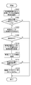
- FIG. 9 is a flowchart showing a process when a user 80 other than the user of the vehicle 30 connects the vehicle 30 to the charge/discharge equipment 20.
- the flowchart of FIG. 9 is mainly executed by the processing unit 42 of the management server 40.
- the process of the flowchart of FIG. 9 is executed, for example, at a time point before a predetermined time from the start time of the scheduled period in which the vehicle 30 transmits and receives power to and from the power network 10.
- the notification control unit 200 selects the vehicle 30 that is stopped near the charging/discharging facility 20 and is not connected to the charging/discharging facility 20. In S904, the notification control unit 200 determines whether or not there is another user 80 near the vehicle 30. For example, in the management server 40, a user 80 who can connect a vehicle 30 other than the own vehicle to the charge/discharge equipment 20 is registered in advance. The notification control unit 200 determines whether there is another user 80 near the vehicle 30 based on the position information acquired from the user terminal 82 of each user 80.
- the notification control unit 200 inquires the user terminal 82 of the user 80 of the vehicle 30 whether the vehicle 30 may be connected to the other user 80 in S906. Send information.
- the connection request control unit 250 determines whether the connection permission information is received from the user terminal 82 that is the destination of the inquiry information.
- the connection request control unit 250 transmits the connection request including the token information to the user terminal 82 of the user 80 near the vehicle 30.
- connection request control unit 250 transmits the token information to vehicle 30.
- the consideration control unit 270 determines whether the vehicle 30 is connected to the charging/discharging facility 20. For example, the consideration control unit 270 determines that the vehicle 30 is connected to the charging/discharging facility 20 when the token information matching the token information transmitted from the management server 40 to the vehicle 30 in S912 is returned from the vehicle 30. ..
- the consideration control unit 270 gives points to the user 80 of the user terminal 82 that is the destination of the connection request.
- the power transmission/reception system 100 it is possible to prevent the vehicle 30 from falling into a state in which it cannot be connected to the charge/discharge equipment 20 during the scheduled period. Therefore, it is possible to guide more vehicles 30 to be connected to the power grid 10. As a result, the power aggregator can easily secure a power transmission/reception capacity that can be exchanged between the vehicle 30 and the power grid 10. As a result, it contributes to the stabilization of the power network 10.
- FIG. 10 illustrates an example computer 2000 in which embodiments of the present invention may be embodied in whole or in part.
- the program installed in the computer 2000 causes the computer 2000 to function as a device such as the management server 40 according to the embodiment or each part of the device, perform an operation associated with the device or each part of the device, and/or
- the process according to the embodiment or the stage of the process can be executed.
- Such programs may be executed by CPU 2012 to cause computer 2000 to perform certain operations associated with some or all of the procedures and block diagrams described herein.
- the computer 2000 includes a CPU 2012 and a RAM 2014, which are mutually connected by a host controller 2010.
- Computer 2000 also includes ROM 2026, flash memory 2024, communication interface 2022, and input/output chip 2040.
- the ROM 2026, the flash memory 2024, the communication interface 2022, and the input/output chip 2040 are connected to the host controller 2010 via the input/output controller 2020.
- the CPU 2012 operates according to the programs stored in the ROM 2026 and the RAM 2014, and controls each unit.
- the communication interface 2022 communicates with other electronic devices via the network.
- the flash memory 2024 stores programs and data used by the CPU 2012 in the computer 2000.
- the ROM 2026 stores a boot program executed by the computer 2000 at the time of activation and/or a program depending on the hardware of the computer 2000.
- the input/output chip 2040 is also used to input/output various input/output units such as a keyboard, a mouse, and a monitor such as a serial port, a parallel port, a keyboard port, a mouse port, a monitor port, a USB port, and an HDMI (registered trademark) port. It may be connected to the input/output controller 2020 via an output port.
- the program is provided via a computer-readable medium such as a CD-ROM, a DVD-ROM, or a memory card, or a network.
- RAM 2014, ROM 2026, or flash memory 2024 are examples of computer readable media.
- the program is installed in the flash memory 2024, the RAM 2014, or the ROM 2026, and is executed by the CPU 2012.
- the information processing described in these programs is read by the computer 2000 and brings about the cooperation between the programs and the various types of hardware resources described above.
- An apparatus or method may be configured by implementing the operation or processing of information according to the use of the computer 2000.
- the CPU 2012 executes the communication program loaded in the RAM 2014, and based on the process described in the communication program, performs the communication process on the communication interface 2022. You may order.
- the communication interface 2022 reads the transmission data stored in the transmission buffer processing area provided in the recording medium such as the RAM 2014 and the flash memory 2024 under the control of the CPU 2012, transmits the read transmission data to the network, and transmits from the network.
- the received data received is written in a reception buffer processing area or the like provided on the recording medium.
- the CPU 2012 causes the RAM 2014 to read all or necessary portions of files or databases stored in a recording medium such as the flash memory 2024, and executes various types of processing on the data in the RAM 2014. Good. The CPU 2012 then writes back the processed data to the recording medium.
- the CPU 2012 performs various types of operations, information processing, conditional judgment, conditional branching, unconditional branching, and information retrieval described in this specification on the data read from the RAM 2014 and designated by the instruction sequence of the program. Various types of processing may be performed, including replacement, and the results written back to RAM 2014. Further, the CPU 2012 may search for information in files, databases, etc. in the recording medium. For example, when a plurality of entries each having the attribute value of the first attribute associated with the attribute value of the second attribute are stored in the recording medium, the CPU 2012 specifies the attribute value of the first attribute. , The entry that matches the condition is searched from the plurality of entries, the attribute value of the second attribute stored in the entry is read, and the first attribute satisfying the predetermined condition is thereby obtained. The attribute value of the associated second attribute may be obtained.
- the program or software module described above may be stored in the computer readable medium on or near the computer 2000.
- a recording medium such as a hard disk or a RAM provided in a server system connected to a dedicated communication network or the Internet can be used as the computer-readable medium.
- the program stored in the computer-readable medium may be provided to the computer 2000 via a network.
- a program installed in the computer 2000 and causing the computer 2000 to function as the management server 40 may work on the CPU 2012 or the like to cause the computer 2000 to function as each unit of the management server 40.
- the information processing described in these programs is read by the computer 2000 to be a specific means in which software and the various hardware resources described above cooperate with each other, the schedule information acquisition unit 210 and the notification control unit 200. , Cancellation information acquisition unit 230, connection permission acquisition unit 240, connection request control unit 250, consideration control unit 270, power transmission/reception control unit 280, demand information acquisition unit 290, schedule information storage unit 282, and history storage unit 284. Then, by implementing the calculation or processing of information according to the purpose of use of the computer 2000 in the present embodiment by these specific means, a specific management server 40 according to the purpose of use is constructed.
- each block may represent (1) a stage of a process in which an operation is performed or (2) each part of a device that is responsible for performing an operation.
- the particular steps and parts are implemented by dedicated circuitry, programmable circuitry provided with computer readable instructions stored on a computer readable medium, and/or a processor provided with computer readable instructions stored on a computer readable medium.
- Dedicated circuits may include digital and/or analog hardware circuits, and may include integrated circuits (ICs) and/or discrete circuits.
- Programmable circuits include memory elements such as logical AND, logical OR, logical XOR, logical NAND, logical NOR, and other logical operations, flip-flops, registers, field programmable gate arrays (FPGA), programmable logic arrays (PLA), and the like.
- Reconfigurable hardware circuitry may be included, including, among others.
- Computer-readable media may include any tangible device capable of storing instructions executed by a suitable device, such that computer-readable media having instructions stored thereon are designated by a procedure or block diagram. Forming at least a portion of a product that includes instructions that can be executed to provide a means for performing the performed operation. Examples of computer readable media may include electronic storage media, magnetic storage media, optical storage media, electromagnetic storage media, semiconductor storage media, and the like.
- the computer-readable medium include a floppy (registered trademark) disk, a diskette, a hard disk, a random access memory (RAM), a read only memory (ROM), an erasable programmable read only memory (EPROM or flash memory), Electrically Erasable Programmable Read Only Memory (EEPROM), Static Random Access Memory (SRAM), Compact Disc Read Only Memory (CD-ROM), Digital Versatile Disc (DVD), Blu-Ray (RTM) Disc, Memory Stick, Integrated Circuit cards and the like may be included.
- a floppy (registered trademark) disk a diskette, a hard disk, a random access memory (RAM), a read only memory (ROM), an erasable programmable read only memory (EPROM or flash memory), Electrically Erasable Programmable Read Only Memory (EEPROM), Static Random Access Memory (SRAM), Compact Disc Read Only Memory (CD-ROM), Digital Versatile Disc (DVD), Blu-Ray (RTM) Disc, Memory Stick, Integrated Circuit cards and the
- Computer readable instructions include assembler instructions, instruction set architecture (ISA) instructions, machine instructions, machine dependent instructions, microcode, firmware instructions, state set data, or object oriented programming such as Smalltalk, JAVA, C++, etc. Language, and any source or object code written in any combination of one or more programming languages, including conventional procedural programming languages such as the "C" programming language or similar programming languages. Good.
- Computer readable instructions are for a general purpose computer, a special purpose computer, or other programmable data processing device processor or programmable circuitry, either locally or in a wide area network (WAN) such as a local area network (LAN), the Internet, or the like. Computer readable instructions may be executed to provide a means for performing the operations specified in the procedures or block diagrams described above. Examples of processors include computer processors, processing units, microprocessors, digital signal processors, controllers, microcontrollers, and the like.
Landscapes
- Engineering & Computer Science (AREA)
- Business, Economics & Management (AREA)
- Human Resources & Organizations (AREA)
- Radar, Positioning & Navigation (AREA)
- Remote Sensing (AREA)
- Strategic Management (AREA)
- Physics & Mathematics (AREA)
- General Physics & Mathematics (AREA)
- Power Engineering (AREA)
- Entrepreneurship & Innovation (AREA)
- Economics (AREA)
- Tourism & Hospitality (AREA)
- Transportation (AREA)
- Mechanical Engineering (AREA)
- Theoretical Computer Science (AREA)
- General Business, Economics & Management (AREA)
- Marketing (AREA)
- Operations Research (AREA)
- Quality & Reliability (AREA)
- Automation & Control Theory (AREA)
- Data Mining & Analysis (AREA)
- Development Economics (AREA)
- Educational Administration (AREA)
- Game Theory and Decision Science (AREA)
- Health & Medical Sciences (AREA)
- General Health & Medical Sciences (AREA)
- Social Psychology (AREA)
- Primary Health Care (AREA)
- Electric Propulsion And Braking For Vehicles (AREA)
- Charge And Discharge Circuits For Batteries Or The Like (AREA)
- Management, Administration, Business Operations System, And Electronic Commerce (AREA)
Abstract
送受電管理装置は、駆動用電源を備える車両が電力網と送受電可能にされる予定期間と車両との対応関係を示す情報を格納する格納部と、予定期間より前の予め定められた時点で車両が電力網と送受電可能にされていない場合に、車両に関連づけられたユーザへの通知を行わせる制御部とを備える。
Description
本発明は、送受電管理装置及びプログラムに関する。
電気自動車の充電に関して、充電ステーションにおいて充電が行われなかったことを加入者に通知する技術が知られている(例えば、下記特許文献1等を参照)。
[先行技術文献]
[特許文献]
[特許文献1] 特許第5432292号公報
[特許文献2] 特開2017-028787号公報
[先行技術文献]
[特許文献]
[特許文献1] 特許第5432292号公報
[特許文献2] 特開2017-028787号公報
バッテリを備える車両と電力網との間で送受電するシステムにおいては、例えば連系可能な送受電設備に実際に接続されている車両のみが、電力網との間で送受電可能となる。したがって、より多くの車両が電力網に接続されていることが望まれる。
本発明の第1の態様においては、送受電管理装置が提供される。送受電管理装置は、駆動用電源を備える車両が電力網と送受電可能にされる予定期間と車両との対応関係を示す情報を格納する格納部を備える。送受電管理装置は、予定期間より前の予め定められた時点で車両が電力網と送受電可能にされていない場合に、車両に関連づけられたユーザへの通知を行わせる通知制御部を備える。
通知制御部は、予定期間より前の予め定められた時点で、車両と電力網との間で電力の送受電を行うための送受電設備に車両が接続されていない場合に、車両に関連づけられたユーザへの通知を行わせてよい。
通知制御部は、車両の現在位置、送受電設備の位置、及び予定期間に基づいて、ユーザへの通知を行わせる時点を決定してよい。
通知制御部は、車両の現在位置、車両の位置情報の履歴、送受電設備の位置、及び予定期間に基づいて、ユーザへの通知を行わせる時点を決定してよい。
通知制御部は、車両の位置情報の履歴から特定される複数の基準移動パターン、車両の現在の移動パターン、送受電設備の位置、及び予定期間に基づいて、ユーザへの通知を行わせる時点を決定してよい。
通知制御部は、複数の基準移動パターンのうち、車両の現在の移動パターンに適合し、かつ、到着先に送受電設備がある基準移動パターンが存在しない場合に、ユーザへの通知をより早い時点で行わせてよい。
通知制御部は、複数の基準移動パターンのうち、車両の現在の移動パターンに適合し、かつ、行先に送受電設備がある基準移動パターンを特定し、予定期間と、当該特定した基準移動パターンに基づく到達予測時刻との差が予め定められた時間差より短くなった時点で、ユーザへの通知を行わせてよい。
通知制御部は、ユーザの現在位置にさらに基づいて、ユーザへの通知を行わせる時点を決定してよい。
通知制御部は、ユーザの現在位置、車両の現在位置、及び予定期間に基づいて、ユーザへの通知を行わせる時点を決定してよい。
通知制御部は、予定期間よりユーザによって予め定められた時間だけ前の時点で、車両が送受電設備に接続されていない場合に、ユーザへの通知を行わせてよい。
通知制御部は、車両に複数のユーザが関連づけられている場合に、車両及び送受電設備により近いユーザへの通知を、より優先して行わせてよい。
通知制御部は、車両の位置情報の履歴から1以上の基準位置を特定し、特定した基準位置から予め定められた範囲内に車両の現在位置が存在しない場合に、ユーザへの通知をより早い時点で行わせてよい。
送受電管理装置は、予定期間より前の予め定められた時点で、車両と電力網との間で電力の送受電を行うための送受電設備に車両が接続されていない場合に、車両を送受電設備に接続することが可能なユーザ以外の人物に、車両を送受電設備に接続するよう依頼する接続依頼制御部を備えてよい。
送受電管理装置は、ユーザから、予定期間における車両と電力網との間の送受電の予定を取り消す旨の取消情報を取得する取消情報取得部をさらに備えてよい。通知制御部は、取消情報を取得した場合に、他の車両のユーザに、予定期間において電力網との間で送受電を行うよう通知してよい。
通知制御部は、予定期間より前において、ユーザが車両から降車してから予め定められた時間が経過した時点で車両が電力網と送受電可能にされていない場合に、ユーザへの通知を行わせてよい。
本発明の第2の態様においては、プログラムが提供される。プログラムは、上記の送受電管理装置として機能させる。
なお、上記の発明の概要は、本発明の必要な特徴の全てを列挙したものではない。また、これらの特徴群のサブコンビネーションもまた、発明となりうる。
以下、発明の実施の形態を通じて本発明を説明するが、以下の実施形態は請求の範囲にかかる発明を限定するものではない。また、実施形態の中で説明されている特徴の組み合わせの全てが発明の解決手段に必須であるとは限らない。なお、図面において、同一または類似の部分には同一の参照番号を付して、重複する説明を省く場合がある。
図1は、送受電システム100の基本構成を概略的に示す。送受電システム100は、例えば電力アグリゲータが、車両が備えるバッテリを用いて、車両と電力網との間の電力を融通するV2G(Vehicle-to-Grid)を行うためのシステムである。送受電システム100は、電力網に車両が接続されることを促進する機能を有する。なお、車両が電力網へ電力を放出すること、及び、車両が電力網から電力を受け取ることの少なくとも何れかを行うことをV2Gと呼ぶ。
送受電システム100は、車両30a及び車両30bを含む複数の車両と、定置バッテリ14と、複数の充放電設備20と、管理サーバ40と、発電設備12と、ユーザ端末82a、ユーザ端末82b及びユーザ端末82cを含む複数のユーザ端末とを備える。
ユーザ80a、ユーザ80b及びユーザ80cは、送受電システム100のユーザである。特に、ユーザ80aは車両30aのユーザであり、ユーザ80bは車両30bのユーザである。なお、車両のユーザとは、車両の所有者や所有者の家族等、車両を使用する任意の人物であってよい。ユーザ80cは、車両30aのユーザではなく、車両30bのユーザでもない。本実施形態において、ユーザ80a、ユーザ80b、ユーザ80cのそれぞれのユーザのことを「ユーザ80」と総称する場合がある。
車両30aは、バッテリ32aを備える。車両30bは、バッテリ32bを備える。本実施形態において、車両30a及び車両30bを含む複数の車両のことを、「車両30」と総称する場合がある。また、バッテリ32a及びバッテリ32bを含む複数のバッテリのことを、「バッテリ32」と総称する場合がある。
なお、バッテリ32は、車両30が備える駆動用電源の一例である。駆動用電源は、燃料電池等のように、燃料を消費して車両30の動力源に提供される電気エネルギーを生成する電源を含む。燃料は、水素や、ガソリン、軽油及び天然ガス等の炭化水素燃料や、アルコール燃料等であってよい。駆動用電源は、車両30の動力源に提供される電気エネルギーを生成することができる任意の電源であってよい。
車両30は、輸送機器の一例である。車両30は、例えば電気自動車、燃料電池自動車(FCV)等、電気エネルギーにより駆動される動力源を備える車両である。電気自動車は、バッテリ式電動輸送機器(BEV)や、動力の少なくとも一部を提供する内燃機関を備えるハイブリッド自動車又はプラグインハイブリッド電気自動車(PHEV)を含む。本実施形態において、車両30は、駆動用電源としてバッテリ32を備える電気自動車である。駆動用電源としてバッテリを採用する形態において、バッテリの放電は、駆動用電源からのエネルギーの放出に対応し、バッテリの充電は、駆動用電源へのエネルギーの蓄積に対応する。また、バッテリの残容量は、駆動用電源から供給可能な電力量又は電気量等、駆動用電源に蓄積されているエネルギー量に対応する。
ユーザ端末82aは、ユーザ80aが使用する通信端末である。ユーザ端末82bは、ユーザ80bが使用する通信端末である。ユーザ端末82cは、ユーザ80cが使用する通信端末である。ユーザ端末82a、ユーザ端末82b及びユーザ端末82cを含む複数のユーザ端末のことを、「ユーザ端末82」と総称する場合がある。
ユーザ端末82は、例えば携帯端末、パーソナルコンピュータ、車両ナビゲーション装置等であってよい。携帯端末としては、携帯電話、スマートフォン、PDA、タブレット、ノートブック・コンピュータ、ラップトップ・コンピュータ、ウエアラブル・コンピュータ等を例示することができる。
管理サーバ40は、通信ネットワークを通じて、車両30、定置バッテリ14、及びユーザ端末82と通信可能である。管理サーバ40はまた、通信ネットワークを通じて、電力取引サーバ50と通信可能である。通信ネットワークは、有線通信又は無線通信の伝送路を含み得る。通信ネットワークは、インターネット、P2Pネットワーク、専用回線、VPN、電力線通信回線、携帯電話回線等を含む通信網を含んでよい。
電力網10は、電力系統の送電系統又は配電系統や、電力グリッドの送電網を含み得る。車両30、定置バッテリ14、充放電設備20、及び発電設備12は、電力網10に接続される。充放電設備20、定置バッテリ14、発電設備12は、電力網10との間で電力の送受電が可能である。
発電設備12は、電力会社等によって管理される。充放電設備20は、例えば、住宅に設置された充放電器や、共同住宅、ビルや商業施設150の駐車場又は公共スペースに設置された充放電スタンド等を含む。
車両30は、充放電ケーブル22を通じて充放電設備20に接続される。すなわち、車両30は、充放電ケーブル22及び充放電設備20を通じて、電力網10に接続される。車両30は、充放電設備20を通じて、バッテリ32と電力網10との間で送受電を行う。例えば、車両30は、バッテリ32の放電により得られた電力を、充放電ケーブル22及び充放電設備20を介して、電力網10へ放出する。また、車両30は、充放電ケーブル22及び充放電設備20を介して電力網10から供給される電力でバッテリ32を充電する。なお、電力網10との間の電力の送受電のことを「電力網10との送受電」等と呼ぶ場合がある。
定置バッテリ14は、電力アグリゲータによって管理される。車両30のバッテリ32は、定置バッテリ14とともに仮想発電所を形成する。管理サーバ40は、電力アグリゲータによって管理される。管理サーバ40は、バッテリ32と電力網10との間、及び、定置バッテリ14と電力網10との間の送受電を制御する。
管理サーバ40は、卸電力市場において入札により電力取引を行う。電力取引サーバ50は、卸電力市場の運営者によって管理される。管理サーバ40は、電力取引サーバ50に対して、30分を1コマとする時間単位で入札する。管理サーバ40は、約定結果に基づいて各コマにおいてバッテリ32及び定置バッテリ14を放電させて、電力網10へ電力を供給する。
例えば、管理サーバ40は、卸電力市場における電力アグリゲータの入札に対する約定量に従って、バッテリ32及び定置バッテリ14を放電させて、バッテリ32及び定置バッテリ14から放出される電力を電力網10へ供給する。また、管理サーバ40は、需給調整市場における電力アグリゲータの入札に対して約定された調整力の範囲内で、バッテリ32及び定置バッテリ14の充放電を制御して、電力網10における電力需給を調整する。例えば、管理サーバ40は、送配電事業者や小売電気事業者からの上げディマンドレスポンス(上げDR)、下げディマンドレスポンス(下げDR)、及び上げ下げディマンドレスポンス(上げ下げDR)に応じて、バッテリ32及び定置バッテリ14の充放電を制御する。
具体的には、管理サーバ40は、上げDRに応じて、車両30及び充放電設備20の少なくとも一方を制御することにより、充放電設備20を通じて電力網10から受け取った電力で車両30のバッテリ32を充電させる。また、管理サーバ40は、下げDRに応じて、車両30及び充放電設備20の少なくとも一方を制御することにより、車両30のバッテリ32を放電させ、バッテリ32の放電によって得られた電力を充放電設備20を通じて電力網10へ向けて放出させる。
本実施形態において、管理サーバ40は、車両30を充放電設備20に接続する予定期間を、車両30のそれぞれのユーザ80から取得する。管理サーバ40は、予定期間より前の予め定められた時点で車両30が充放電設備20に接続されていない場合に、車両30のユーザ80に接続確認通知を送信する。例えば、ユーザ80は勤務先から帰宅後に車両30を充放電設備20に接続する行動を予定しており、勤務先から通常30分で自宅に帰ることができる場合には、予定期間の開始時刻の40分前に車両30が勤務先付近に駐車されているときに、ユーザ80に接続確認通知を送信する。これにより、ユーザ80が車両30を充放電設備20に接続できない状況になる可能性を低減することができる。したがって、電力アグリゲータは、車両30と電力網10との間で送受電可能な容量を確保し易くなる。
なお、本実施形態において、送受電とは、車両30及び電力網10の少なくとも一方から他方への電力の受け渡しが生じることを意味する。例えば、送受電とは、車両30から電力網10に向けた電力の放出が行われることを意味してよい。また、送受電とは、電力網10から車両30に向けた送電が行われることを意味してよい。なお、自宅等の電力需要家に設置した充放電器を通じて車両30が電力を放出する場合において、電力需要家側の消費電力が車両30から放出される電力より大きいときには、電力需要家側と電力網10との接続点において電力網10への正味の電力供給は生じず、接続点から電力需要家への電力供給量が単に減少するだけの場合がある。この場合でも、電力網10から見ると、電力網10外との間で電力の受け渡しが生じたとみなすことができる。したがって、本実施形態において、車両30が電力を放出する場合における電力網10との送受電において、電力網10が車両30との間の特定の接続点から正味の電力を受け取るか否かは問わない。
図2は、管理サーバ40の機能構成を概略的に示す。管理サーバ40は、処理部42と、格納部48と、通信部46とを備える。
処理部42は、プロセッサを含む処理装置により実現される。格納部48は、不揮発性の記憶装置により実現される。処理部42は、格納部48に格納された情報を用いて処理を行う。通信部46は、車両30、定置バッテリ14、ユーザ端末82、及び電力取引サーバ50との間の通信を担う。通信部46が車両30、定置バッテリ14、ユーザ端末82及び電力取引サーバ50から受信した情報は、処理部42に供給される。また、車両30、定置バッテリ14、ユーザ端末82及び電力取引サーバ50へ送信される情報は、処理部42により生成され、通信部46を介して送信される。
管理サーバ40は、送受電管理装置として機能する。管理サーバ40は、1つの情報処理装置で実現されるシステムであってよいし、複数の情報処理装置で実現されるシステムであってもよい。
処理部42は、予定情報取得部210と、通知制御部200と、取消情報取得部230と、接続許可取得部240と、接続依頼制御部250と、対価制御部270と、送受電制御部280と、需要情報取得部290とを備える。格納部48は、予定情報格納部282と、履歴格納部284とを備える。
予定情報格納部282は、バッテリ32を備える車両30が電力網10と送受電可能にされる予定期間と車両30との対応関係を示す情報を格納する。通知制御部200は、予定期間より前の予め定められた時点で車両30が電力網10と送受電可能にされていない場合に、車両30に関連づけられたユーザ80への通知を行わせる。例えば、通知制御部200は、予定期間より前の予め定められた時点で、車両30と電力網10との間で電力の送受電を行うための充放電設備20に車両30が接続されていない場合に、車両30に関連づけられたユーザ80への通知を行わせる。具体的には、送受電制御部280は、充放電設備20に車両30が接続されていない場合に、通信部46を通じて、接続確認通知をユーザ端末82に送信する。なお、充放電設備20は、送受電設備の一例である。
通知制御部200は、車両30の現在位置、記充放電設備20の位置、及び予定期間に基づいて、ユーザ80への通知を行わせる時点を決定してよい。通知制御部200は、車両30の現在位置、車両30の位置情報の履歴、充放電設備20の位置、及び予定期間に基づいて、ユーザ80への通知を行わせる時点を決定してよい。
通知制御部200は、車両30の位置情報の履歴から特定される複数の基準移動パターン、車両30の現在の移動パターン、充放電設備20の位置、及び予定期間に基づいて、ユーザ80への通知を行わせる時点を決定してよい。基準移動パターンとしては、ユーザ80の勤務先とユーザ80の自宅との間で車両30が移動する経路を例示することができる。通知制御部200は、複数の基準移動パターンのうち、車両30の現在の移動パターンに適合し、かつ、到着先に充放電設備20がある基準移動パターンが存在しない場合に、ユーザ80への通知をより早い時点で行わせてよい。
通知制御部200は、複数の基準移動パターンのうち、車両30の現在の移動パターンに適合し、かつ、行先に充放電設備20がある基準移動パターンを特定し、予定期間と、当該特定した基準移動パターンに基づく到達予測時刻との差が予め定められた時間差より短くなった時点で、ユーザ80への通知を行わせてよい。
通知制御部200は、車両30の位置情報の履歴に基づいて1以上の基準位置を特定し、特定した基準位置から予め定められた範囲内に車両30の現在位置が存在しない場合に、ユーザ80への通知をより早い時点で行わせてよい。
通知制御部200は、ユーザ80の現在位置にさらに基づいて、ユーザ80への通知を行わせる時点を決定してよい。例えば、通知制御部200は、ユーザ80と車両30との間の距離が長いほど、ユーザ80への通知をより早い時点で行わせてよい。通知制御部200は、ユーザ80の現在位置が車両30の現在位置から予め定められた範囲内に存在しない場合、ユーザ80の現在位置が車両30の現在位置から予め定められた範囲内に存在する場合に比べて、ユーザ80への通知を早い時点で行わせてよい。このように、通知制御部200は、ユーザ80の現在位置、車両30の現在位置、充放電設備20の位置、及び予定期間に基づいて、ユーザ80への通知を行わせる時点を決定してよい。
なお、通知制御部200は、ユーザ80の現在位置、車両30の現在位置、及び予定期間に基づいて、ユーザ80への通知を行わせる時点を決定してよい。例えば、車両30の現在位置が充放電設備20の位置から予め定められた範囲内に存在する場合に、通知制御部200は、ユーザ80の現在位置、車両30の現在位置、及び予定期間に基づいて、ユーザ80への通知を行わせる時点を決定してよい。例えば、通知制御部200は、予定期間より、ユーザ80の現在位置と車両30の現在位置との間の距離に応じた時間だけ前の時点で、車両30が充放電設備20に接続されていない場合に、ユーザ80への通知を行わせてよい。
通知制御部200は、予定期間よりユーザ80によって予め定められた時間だけ前の時点で、車両30が充放電設備20に接続されていない場合に、ユーザ80への通知を行わせてよい。例えば、ユーザ80によって「予め定められた時間」として「1時間」が設定されている場合、通知制御部200は、予定期間の開始時刻より1時間前の時点で、車両30が充放電設備20に接続されていない場合に、ユーザ80への通知を行わせてよい。
取消情報取得部230は、ユーザ80から、予定期間における車両30と電力網10との間の送受電の予定を取り消す旨の取消情報を取得する。通知制御部200は、取消情報を取得した場合に、他の車両30のユーザ80に、予定期間において電力網10との間で送受電を行うよう通知する。
なお、通知制御部200は、予定期間より前において、ユーザ80が車両30から降車してから予め定められた時間が経過した時点で車両30が電力網10と送受電可能にされていない場合に、ユーザ80への通知を行わせてよい。例えば、通知制御部200は、ユーザ80が車両30から降車して5分が経過した時点で車両30が充放電設備20に接続されていない場合に、ユーザ80に通知を行わせてよい。
また、通知制御部200は、車両30に複数のユーザ80が関連づけられている場合に、車両30及び充放電設備20により近いユーザ80への通知を、より優先して行わせてよい。例えば、車両30を通勤に利用するユーザ80が勤務先におり、通常は通勤に利用される車両30が例外的に自宅にあるような場合において、ユーザ80の家族が自宅にいるときには、通知制御部200はユーザ80の家族への通知を、ユーザ80への通知より優先させてよい。
接続依頼制御部250は、予定期間より前の予め定められた時点で、車両30と電力網10との間で電力の送受電を行うための充放電設備20に車両30が接続されていない場合に、車両30を充放電設備20に接続することが可能なユーザ以外のユーザ80に、車両30を充放電設備20に接続するよう依頼する。接続許可取得部240は、車両30のユーザ以外のユーザ80が車両30を充放電設備20に接続することを許可する許可情報を、車両30のユーザ80から取得する。接続依頼制御部250は、接続許可取得部240が許可情報を取得したことを条件として、車両30を充放電設備20に接続するよう他のユーザ80に依頼してよい。
対価制御部270は、接続依頼制御部250が接続を依頼したユーザ80によって車両30が充放電設備20に接続された場合に、そのユーザ80に対価情報を対応づける。なお、車両30aのユーザ以外のユーザ80は、ユーザ80b及びユーザ80cを含み得る。また、車両30bのユーザ以外のユーザ80は、ユーザ80a及びユーザ80cを含み得る。
需要情報取得部290は、電力網10における電力需要を示す情報を取得する。送受電制御部280は、電力網10における電力需要に応じて、車両30に電力網10との間で送受電を行わせる。
送受電制御部280は、車両30のECUと通信して、車両30が電力網10と送受電可能な充放電設備20に接続されているか否かを示す送受電可否情報を逐次取得する。送受電制御部280は、車両30が電力網10との間で送受電可能である場合に、需要情報取得部290が取得した電力需要に応じて、車両30が備えるECUに対して、バッテリ32の充放電を指示する。車両30のECUは、送受電制御部280の指示に従って、充放電設備20と通信し、車両30の電力変換器を制御して、充放電設備20を通じたバッテリ32の充電や、バッテリ32の放電により得られる電力の放出を行う。なお、送受電制御部280は、バッテリ32の充電時における充放電設備20から電力変換器への入力電力量、バッテリ32の放電時における当該電力変換器から充放電設備20への出力電力量、及びバッテリ32のSOC(State of Charge)を示す情報を、車両30のECUから逐次取得してよい。送受電制御部280は、車両30のECUから取得した情報に基づいて、車両30と電力網10との間の送受電を制御してよい。
なお、上述した電力取引における約定量は、電力需要を示す情報の一例である。電力需要を示す情報とは、電力取引における約定価格や、買い約定であるか売り約定であるかを示す約定種別であってよい。また、電力需要を示す情報とは、電力網10におけるリアルタイムの需給アンバランス量を示す情報であってもよいし、将来における需給アンバランス量の予測値を示す情報であってもよい。電力需要を示す情報とは、電力網10の電力需要家のリアルタイムの消費電力量又は当該消費電力の予測値を示す情報であってもよい。電力需要を示す情報として、電力量そのものに限らず、気温情報、湿度情報、気象情報、催事情報等、電力需要に直接的又は間接的に影響を与える様々な情報を適用できる。
なお、電力取引市場としては、一日前市場、当日市場、需給調整力市場等の取引市場を例示できる。電力取引の取引形態としては、これらの電力取引市場における取引形態以外の様々な取引形態を適用できる。
管理サーバ40によれば、ユーザ80が予定した期間に車両30を充放電設備20に接続できるように促すことができる。そのため、電力アグリゲータは、車両30と電力網10との間での送受電容量を確保し易くなる。ひいては、電力網10の安定化に寄与する。
なお、送受電管理装置の機能は、管理サーバ40単独で実現されてよいし、管理サーバ40と車両30のECUとの組み合わせによって実現されてよい。例えば、管理サーバ40が実行する処理の少なくとも一部を、車両30のECUが実行してよい。例えば、予定情報取得部210、通知制御部200、取消情報取得部230、接続許可取得部240、接続依頼制御部250、対価制御部270、送受電制御部280、需要情報取得部290、予定情報格納部282、履歴格納部284により実現される機能の少なくとも一部が、車両30のECUにより実現されてよい。
図3は、車両30を充放電設備20に接続する予定期間を設定するための画面300の一例を示す。画面300は、管理サーバ40の制御により、ユーザ端末82に表示される。画面300は、選択メニュー310と、選択メニュー312と、予定期間の入力メニュー320と、決定ボタン330とを含む。
選択メニュー310は、充放電設備20に接続する対象となる車両30を選択するためのメニューである。入力メニュー320は、接続予定日と、接続予定日における接続予定時間の開始時刻と、当該予定時間の終了時刻と、通知タイミングを設定するためのメニューである。予定期間は、接続予定日と、開始時刻と、終了時刻とにより定まる。なお、接続予定日には、特定の日付自体を設定する他、「平日」、「土日」、「土休日」、「10月」等の情報によって、1以上の日を設定可能であってよい。接続予定時間の開始時刻及び終了時刻は、30分のコマ単位や、1時間単位等、任意の単位で設定可能であってよい。通知タイミングは、接続予定期間の開始時刻から何時間前の時点でユーザ80に通知するかを示す。通知タイミングは、例えば、「自動」、「10分前」、「30分前」、「1時間前」等の中から選択可能であってよい。「自動」が選択された場合、管理サーバ40は、車両30の現在位置、充放電設備20の位置、及びユーザ80の現在位置等に基づいて、通知タイミングを動的に決定する。
選択メニュー312は、車両30を接続する予定の充放電設備20を選択するためのメニューである。接続予定となる充放電設備20の選択肢は、予めユーザ端末82に登録されていてよい。また、ユーザ端末82は、過去に車両30が接続された複数の充放電設備20の履歴を管理サーバ40から取得し、当該複数の充放電設備20の中の1つ以上の充放電設備20を、接続予定となる充放電設備20の選択肢として、選択メニュー312で提示してよい。
ユーザ80が決定ボタン330を押すと、ユーザ端末82は、ユーザ80の識別情報、車両30の識別情報、予定期間、及び接続予定の充放電設備20の識別情報を示す情報を、管理サーバ40に送信する。管理サーバ40において、予定情報取得部210は、ユーザ端末82から送信された車両30の識別情報、予定期間を示す情報、及び接続予定の充放電設備20の識別情報を、ユーザ80の識別情報に対応づけて、予定情報格納部282に格納する。
なお、ユーザ80は、ユーザ端末82で管理サーバ40にアクセスして、予定期間及び接続予定の充放電設備20を自ら設定してよい。また、予定情報取得部210は、需要情報取得部290が取得した電力需要や、ユーザ80や車両30の移動履歴に基づいて、ユーザ80に提示する予定期間及び充放電設備20を決定し、決定した予定期間を示す情報及び充放電設備20の識別情報をユーザ端末82にプッシュ通知で送信し、提示した予定期間に車両30を充放電設備20に接続することを受け入れる否かをユーザ80に選択させることによって、予定期間及び接続予定の充放電設備20の情報を取得してよい。
図4は、予定情報の一例をテーブル形式で示す。予定情報は、格納部48における予定情報格納部282に格納される。予定情報は、車両IDと、ユーザIDと、予定期間と、充放電設備IDとを示す情報とを対応づける。
車両IDには、車両30の識別情報が格納される。車両IDには、図3等に示す画面300を通じてユーザ80が設定した車両30の識別情報が格納されてよい。ユーザIDには、ユーザ80の識別情報が格納される。予定期間には、ユーザ80の車両30を充放電設備20に接続する予定期間を示す情報が格納される。予定期間には、図3等に示す画面300の選択メニュー310を通じてユーザ80が設定した予定期間を示す情報が格納されてよい。充放電設備IDには、車両30が接続される予定の充放電設備20の識別情報が格納される。充放電設備IDには、図3等に示す画面300の選択メニュー312を通じてユーザ80が選択した接続予定の充放電設備20の識別情報が格納されてよい。
図5は、車両30の位置履歴を示す履歴情報の一例をテーブル形式で示す。履歴情報は、格納部48に格納される。履歴情報は、車両IDと、出発地と、到着地と、経路情報と、時刻情報とを対応づける。
車両IDには、車両30の識別情報が格納される。出発地には、車両30の移動開始位置を示す情報が格納される。到着地には、車両30が移動を終了した位置を示す情報が格納される。経路情報には、出発地から到着地までの車両30の移動経路を示す情報が格納される。経路情報には、移動経路上のノード情報とノードを結ぶリンク情報とが格納されてよい。時刻情報は、出発地から到着地までの車両30の移動経路上における時刻を示す情報が格納される。例えば、時刻情報には、出発日時、車両30が移動経路上のノードを通過した日時、及び到着日時が格納される。
出発地、到着地及び経路情報は、車両30の移動パターンを示す情報の一例である。通知制御部200は、履歴格納部284に格納された出発地、到着地及び経路情報と、時刻情報とに基づいて、1日の各時間帯における車両30の代表的な基準経路を特定する。通知制御部200は、基準経路に従って車両30が移動すると仮定して、車両30が充放電設備20への到着時刻を予測して、予定期間と到着予測時刻との差が予め定められた時間未満になった時点で、接続確認通知を送信する。
なお、図5に示す履歴情報は、車両30の位置履歴を示す情報の一例である。例えば、履歴格納部284は、経路情報ではなく、車両30の地理的位置を日時に対応づけた時系列の位置データを格納してよい。
図6は、履歴情報に基づいて接続確認通知の送信可否を判断する処理を説明するための図である。図6において、P1はユーザ80の勤務先の位置を示し、P2はユーザ80の自宅の位置を示すとする。ユーザ80の自宅には充放電設備20が設けられているものとする。
例えば、履歴格納部284には、ユーザ80の識別情報に対応づけられた過去半年の履歴情報として、平日の夕方の時間帯において、出発地P1からノードN1、ノードN2、及びノードN3を順に通過して到着地P2に到る経路700が予め定められた数以上格納されているとする。また、履歴格納部284には、ユーザ80の識別情報に対応づけられた過去半年の履歴情報として、平日の夕方の時間帯において、出発地P1からノードN1及びノードN4を順に通過して到着地P3に到り、P3に到着して20分後に出発地P3からノードN4及びノードN3を順に通過して到着地P2に到る経路710が、予め定められた数以上格納されていたとする。また、履歴格納部284には、ユーザ80の識別情報に対応づけられた過去半年の履歴情報として、平日の夕方の時間帯において、出発地P1からノードN1、ノードN5、ノードN6、ノードN7を順に通過して到着地P4に到る経路720が、予め定められた数以上格納されていたとする。なお、経路700の平均所要時間は30分であり、経路710の平均所要時間が50分であったとする。
経路700、経路710及び経路720は、履歴情報に予め定められた数以上格納された経路であるため、車両30の移動経路として代表的な経路である基準経路とみなすことができる。また、P1及びP3は、基準経路における出発地又は基準経路に含まれる経路の出発地である。したがって、P1及びP3は、車両30の位置として代表的な位置である基準位置とみなすことができる。
ここで、車両30の現在位置がP1の近くの駐車場内にあるとき、通知制御部200は、予定期間の開始時刻の40分前の時点までは、ユーザ80に接続確認通知を送信しない。通知制御部200は、予定期間の開始時刻の40分未満になった時点で、ユーザ端末82に接続確認通知を送信する。接続確認通知を送信する時点を定める「40分前」は、P1を出発地とする基準経路700及び基準経路710の平均所要時間の最短値である30分に、予め定められた猶予時間である10分を加えた値から定められる。このように、車両30の現在位置が基準位置から予め定められた範囲内にあるときには、通知制御部200は、充放電設備20に接続する予定期間の開始時刻に間に合わなくなる少し前のタイミングで、ユーザ80に接続確認通知を送信することができる。そのため、ユーザ80に送信される接続確認通知の数を削減することができる。したがって、ユーザ80が接続確認通知を煩わしく感じることを抑制することができる。
一方、車両30の現在位置がP1から離れたP4にあるとき、通知制御部200は、P4からP2に移動するのに必要な時間を算出し、予定期間の開始時刻の30分前までに車両30がP2まで移動できないと判断された時点で、接続確認通知をユーザ端末82に送信する。このように、ユーザ80がいつもとは異なる位置にいる場合には、より早い時点でユーザ80に接続確認通知を送信することができる。そのため、ユーザ80がいつもどおりの行動パターンから外れた行動パターンをとっている場合でも、車両30を充放電設備20に接続することをユーザ80が忘れないようにすることができる。
また、車両30がP1を出発してノードN1及びノードN2を通過した後、ノードN2とノードN3とを結ぶリンクとは異なるリンク上を移動している場合、通知制御部200は、ノードN2から予め定められた距離だけ離れた地点750に車両30が到達した時点で、車両30の移動経路が基準経路700から乖離したと判断して、接続確認通知をユーザ端末82に送信してよい。
なお、車両30がP1を出発して経路720を移動中の場合、経路720の到着地P4に充放電設備20が設置されており、車両30が予定時間の開始時刻前までに到着地P4に到着できると予測されるときは、通知制御部200は、P4に設置された充放電設備20及びP2に設置された充放電設備20が同一の電力網10との間で送受電可能であることを条件として、接続確認通知をユーザ端末82に送信しなくてよい。このケースにおいて、通知制御部200は、車両30がP4に到着した場合に、接続確認通知をユーザ端末82に送信してよい。また、通知制御部200は、車両30がP4に到着した後、車両30が充放電設備20に接続されずに予め定められた時間が経過した場合に、接続確認通知をユーザ端末82に送信してよい。例えば、通知制御部200は、ユーザ80が車両30から降車した後、充放電設備20に接続されずに5分が経過した場合に、接続確認通知をユーザ端末82に送信してよい。
なお、通知制御部200が接続確認通知をユーザ端末82に送信した後において、取消情報取得部230がユーザ80から充放電設備20への接続を取り消す旨を受信した場合、通知制御部200は、予め定められた数の他の車両30のユーザ80に、充放電設備20に接続するよう通知してよい。これにより、電力アグリゲータは、電力網10との間で送受電するべき電力量が不足しないようにすることができる。
このように、管理サーバ40によれば、ユーザ80の行動がいつもどおりの行動から外れている場合は、早めに接続確認通知を送信することができる。これにより、ユーザ80が車両30を充放電設備20に接続し忘れることがないようにすることができる。
図7は、接続確認通知の送信に関する処理を示すフローチャートである。図7のフローチャートは、主として管理サーバ40の処理部42において実行される。図7のフローチャートの処理は、例えば、管理サーバ40において定期的に実行される。
S702において、通知制御部200は、車両30が移動中であるか否かを判断する。車両30が移動中である場合、S704において、履歴情報を参照して、現時刻を含む時間帯に対応づけられた基準経路のうち、到着地に充放電設備20が設置されている経路を検索して、経路が検索されたか否かを判断する(S706)。経路が検索された場合、S708において、予定期間の開始時刻の10分前までに到着地に到着できるか否かを判断する。
予定期間の開始時刻の10分前までに到着地に到着できない場合、S710において、通知制御部200は、接続確認通知をユーザ端末82に送信する。例えば、通知制御部200は、予定期間の開始時刻を含む接続確認通知をユーザ端末82に送信する。S712において、充放電設備20への車両30の接続予定を取り消すか否かを判断する。例えば、取消情報取得部230は、接続予定を取り消すか否かの問合せをユーザ端末82に送信し、問合せの送信に応じてユーザ端末82から取消通知を取得した場合に、予定期間における充放電設備20への車両30の接続予定を取り消すと判断する。
充放電設備20への車両30の接続予定を取り消す場合、S714において、他の車両30のユーザ80に、充放電設備20に接続するよう通知する。充放電設備20への車両30の接続予定を取り消さない場合、本フローチャートの処理を終了する。
また、S708の判断において、予定期間の開始時刻の10分前までに車両30が到着地に到着できると判断した場合、接続確認通知を送信せずに、本フローチャートの処理を終了する。また、S706において、到着地に充放電設備20が設置されている経路が検索されなかった場合、S710に処理を移行して、通知制御部200は接続確認通知をユーザ端末82に送信する。
S702の判断において、車両30が移動中でないと判断した場合、S720において、通知制御部200は、車両30の現在位置が基準位置から予め定められた範囲内にあるか否かを判断する。車両30の現在位置が基準位置から予め定められた範囲内にある場合、S722において、予定期間の開始時刻の10分前までに車両30が充放電設備20まで移動できるか否かを判断する。例えば、通知制御部200は、上述したように、現在位置を出発地とする基準経路の所要時間のうち最短の所要時間に基づいて、車両30が10分前までに充放電設備20に移動できるか否かを判断する。
予定期間の開始時刻の10分前までに充放電設備20に移動できないと判断した場合、S710に処理を移行して、通知制御部200は接続確認通知をユーザ端末82に送信する。予定期間の開始時刻の10分前まで移動できると判断した場合、接続確認通知を送信せずに、本フローチャートの処理を終了する。
S720の判断において、車両30の現在位置が基準位置から予め定められた範囲内にないと判断した場合、S724において、車両30が予定期間の開始時刻の30分前までに充放電設備20に移動できるか否かを判断する。車両30が開始時刻の30分前までに充放電設備20に移動できない場合、S710に処理を移行して、通知制御部200は接続確認通知をユーザ端末82に送信する。車両30が開始時刻の30分前までに充放電設備20に移動できる場合、接続確認通知を送信せずに、本フローチャートの処理を終了する。
このように、車両30の現在位置が基準位置の近傍にある場合は接続確認通知を送信する猶予時間を短くし、車両30の現在位置が基準位置の近傍にない場合は猶予時間を長くする。これにより、ユーザ80に不必要な接続確認通知が送信されることを抑制しつつ、ユーザ80が車両30を充放電設備20に接続し損ねることのないようにすることができる。
なお、S722において、ユーザ80の現在位置及び車両30の現在位置を更に考慮して判断してよい。例えば、通知制御部200は、予定期間の開始時刻の10分前までに車両30が充放電設備20まで移動できるか否かを、ユーザ80が現在位置から車両30の現在位置まで移動する時間と、車両30の現在位置から充放電設備20までの移動にかかる所要時間とに基づいて判断してよい。このように、通知制御部200は、ユーザ80の現在位置、車両30の現在位置、充放電設備20の位置、及び予定期間に基づいて、接続確認通知を送信する時点を決定してよい。
図7は、図3の選択メニュー310を通じて通知タイミングとして「自動」が選択された場合のフローチャートである。通知タイミングとして「自動」以外の時間が選択されている場合、通知制御部200は、予定期間の開始時刻より、通知タイミングとして選択された時間だけ前の時点で、車両30が充放電設備20に接続されていない場合に、接続確認通知を送信させてよい。
図8は、車両30のユーザ以外のユーザ80が車両30を充放電設備20に接続する場合のやりとりを概略的に示す。図8に関連して、ユーザ80cが、ユーザ80aに代わって車両30aを接続する場合を取り上げて説明する。
図8において、車両30aは、充放電設備20に接続されていない状態で、駐車場等に駐車されているものとする。また、ユーザ80aは、車両30aから離れた場所におり、車両30aを充放電設備20にすぐに接続することができないものとする。
車両30aを充放電設備20に接続する予定期間の開始時刻から予め定められた時間だけ前の時点において、車両30aが充放電設備20に接続されておらず、かつ、ユーザ80aが車両30aから予め定められた距離以上離れている場合、通知制御部200は、他のユーザが車両30aを充放電設備20に接続してよいか否かを問合せる問合せ情報を、ユーザ80aのユーザ端末82aに送信する。ユーザ80aが、他のユーザが車両30aを充放電設備20に接続することを許可する旨の操作をユーザ端末82aに対して行うと、ユーザ端末82aは管理サーバ40に接続許可情報を送信する。
ユーザ端末82からの接続許可情報を取得すると、接続依頼制御部250は、車両30aの近くにいるユーザ80cを検索して、車両30aを充放電設備20に接続するためのトークン情報を含む接続依頼を、ユーザ端末82cに送信する。トークン情報は、車両30aを充放電設備20に接続することが許可されたユーザ80を限定するための情報である。後述するように、車両30aにも同じトークン情報が送信され、車両30aは、ユーザ80cが車両30aを充放電設備20に接続する許可を受けているか否かを、トークン情報によって判断する。なお、接続依頼制御部250は、車両30aを特定する情報を接続依頼に含めてよい。車両30aを特定する情報としては、車両30aの自動車登録番号標の番号、格納部48に予め格納されている車両30aの画像、車両30aの位置情報等を例示することができる。接続依頼制御部250は、車両30aのECUに、方向指示器や非常点滅表示灯等の発光装置を予め定められたパターンで点滅させることによって、ユーザ80cに車両30aを認知させてよい。なお、接続依頼制御部250は、ユーザ端末82cに送信したトークン情報と同じトークン情報を車両30aにも送信する。
ユーザ80cがユーザ端末82cを車両30aに近づけると、ユーザ端末82cは、近距離無線通信によって車両30aのECUにトークン情報を送信する。車両30aのECUは、管理サーバ40から受信したトークン情報とユーザ端末82cから受信したトークン情報が一致すると、車両30aに充放電ケーブル22が接続されることを許容する。例えば、車両30aのECUは、車両30aの充放電ケーブル装着口の蓋を開く。
車両30aのECUは、充放電ケーブル22が車両30aの充放電ケーブル装着口に充放電ケーブル22が装着されたことを検出すると、管理サーバ40から受信したトークン情報を管理サーバ40に返送する。対価制御部270は、車両30aからトークン情報を受信すると、当該トークン情報を含む接続依頼の宛先のユーザ80cに対して、車両30aを充放電設備20に接続したことに対する対価を示す対価情報を生成して、生成した対価情報をユーザ80cに対応づける。例えば、対価制御部270は、ユーザ80cにポイントを付与する。
これにより、車両30が予定期間に充放電設備20に接続されずに放置されている場合でも、他のユーザ80に接続してもらうことができる。そのため、車両30が電力網10に接続される確率を高めることができる。
なお、図8に関連する説明では、車両30aを充放電設備20に接続することが予定されているものとした。しかし、車両30aを充放電設備20に接続する予定がない場合であっても、他のユーザ80に車両30aを充放電設備20に接続してもらえるようにしてよい。例えば、取消情報取得部230が車両30bのユーザ80bから取消情報を取得した場合において、車両30bの予定時間に車両30aを充放電設備20に接続するようユーザ80aに通知するときに、通知制御部200は、上述した問合せ情報をユーザ80aに送信してよい。
図8の例では、ユーザ80cが車両30aを充放電設備20に接続するケースを取り上げて説明したが、ユーザ80bも、車両30aを充放電設備20に接続する他のユーザとなり得る。また、ユーザ80a及びユーザ80cは、車両30bを充放電設備20に接続する他のユーザとなり得る。
ユーザ80に付与されたポイントは、商業施設150で購入する商品の代価として使用可能であってよい。また、ユーザ80に付与されたポイントは、緊急時や災害時に車両30を定置バッテリ14で充電するために使用可能であってよい。例えば、管理サーバ40の処理部42は、ユーザ80に予め定められた値以上のポイントが付与されている場合、ユーザ80の車両30のバッテリ32の残容量が予め定められた値より低いことを条件として、ユーザ80に提供されている現在ポイントから予め定められた数のポイントを減算することと引き換えに、定置バッテリ14によるバッテリ32の充電を許可してよい。
図9は、車両30のユーザ以外のユーザ80が車両30を充放電設備20に接続する場合の処理を示すフローチャートである。図9のフローチャートは、主として管理サーバ40の処理部42において実行される。図9のフローチャートの処理は、例えば、車両30が電力網10との間で送受電を行う予定期間の開始時刻から予め定められた前の時点で実行される。
S902において、通知制御部200は、充放電設備20の近くに停車しており、かつ、充放電設備20に接続されていない車両30を選択する。S904において、通知制御部200は、車両30の近くに他のユーザ80がいるか否かを判断する。例えば、管理サーバ40には、自車以外の車両30を充放電設備20に接続することができるユーザ80が予め登録されている。通知制御部200は、各ユーザ80のユーザ端末82から取得した位置情報に基づいて、車両30の近くに他のユーザ80がいるか否かを判断する。
車両30の近くに他のユーザ80がいる場合、S906において、通知制御部200は、車両30のユーザ80のユーザ端末82に、他のユーザ80に車両30を接続してよいか否かの問合せ情報を送信する。S908において、接続依頼制御部250は、問合せ情報の宛先のユーザ端末82から接続許可情報を受信したか否かを判断する。接続許可情報受信した場合、S910において、接続依頼制御部250は、車両30の近くのユーザ80のユーザ端末82に、トークン情報を含む接続依頼を送信する。S912において、接続依頼制御部250は、当該トークン情報を、車両30に送信する。
S914において、対価制御部270は、車両30が充放電設備20に接続されたか否かを判断する。例えば、対価制御部270は、S912において管理サーバ40から車両30に送信されたトークン情報に一致するトークン情報が車両30から返送された場合に、車両30が充放電設備20に接続されたと判断する。
S914の判断において車両30が充放電設備20に接続されたと判断した場合、対価制御部270は、接続依頼の宛先のユーザ端末82のユーザ80にポイントを付与する。
なお、S904において車両30の近くに他のユーザ80がいないと判断した場合、本フローチャートの処理を終了する。また、S908において、問合せ情報の宛先のユーザ端末82から接続許可情報を受信しなかった場合や、S914において車両30が充放電設備20に接続されなかった場合も、本フローチャートの処理を終了する。
以上に説明した送受電システム100によれば、車両30が予定期間に充放電設備20に接続できない状態に陥ることを抑制することができる。そのため、より多くの車両30が電力網10に接続されるように誘導することができる。これにより、電力アグリゲータは、車両30と電力網10との間でやりとり可能な送受電容量を確保し易くなる。ひいては電力網10の安定化に寄与する。
図10は、本発明の複数の実施形態が全体的又は部分的に具現化され得るコンピュータ2000の例を示す。コンピュータ2000にインストールされたプログラムは、コンピュータ2000に、実施形態に係る管理サーバ40等の装置又は当該装置の各部として機能させる、当該装置又は当該装置の各部に関連付けられるオペレーションを実行させる、及び/又は、実施形態に係るプロセス又は当該プロセスの段階を実行させることができる。そのようなプログラムは、コンピュータ2000に、本明細書に記載の処理手順及びブロック図のブロックのうちのいくつか又はすべてに関連付けられた特定のオペレーションを実行させるべく、CPU2012によって実行されてよい。
本実施形態によるコンピュータ2000は、CPU2012、及びRAM2014を含み、それらはホストコントローラ2010によって相互に接続されている。コンピュータ2000はまた、ROM2026、フラッシュメモリ2024、通信インタフェース2022、及び入力/出力チップ2040を含む。ROM2026、フラッシュメモリ2024、通信インタフェース2022、及び入力/出力チップ2040は、入力/出力コントローラ2020を介してホストコントローラ2010に接続されている。
CPU2012は、ROM2026及びRAM2014内に格納されたプログラムに従い動作し、それにより各ユニットを制御する。
通信インタフェース2022は、ネットワークを介して他の電子デバイスと通信する。フラッシュメモリ2024は、コンピュータ2000内のCPU2012によって使用されるプログラム及びデータを格納する。ROM2026は、アクティブ化時にコンピュータ2000によって実行されるブートプログラム等、及び/又はコンピュータ2000のハードウエアに依存するプログラムを格納する。入力/出力チップ2040はまた、キーボード、マウス及びモニタ等の様々な入力/出力ユニットをシリアルポート、パラレルポート、キーボードポート、マウスポート、モニタポート、USBポート、HDMI(登録商標)ポート等の入力/出力ポートを介して、入力/出力コントローラ2020に接続してよい。
プログラムは、CD-ROM、DVD-ROM、又はメモリカードのようなコンピュータ可読媒体又はネットワークを介して提供される。RAM2014、ROM2026、又はフラッシュメモリ2024は、コンピュータ可読媒体の例である。プログラムは、フラッシュメモリ2024、RAM2014、又はROM2026にインストールされ、CPU2012によって実行される。これらのプログラム内に記述される情報処理は、コンピュータ2000に読み取られ、プログラムと上記様々なタイプのハードウエアリソースとの間の連携をもたらす。装置又は方法が、コンピュータ2000の使用に従い情報のオペレーション又は処理を実現することによって構成されてよい。
例えば、コンピュータ2000及び外部デバイス間で通信が実行される場合、CPU2012は、RAM2014にロードされた通信プログラムを実行し、通信プログラムに記述された処理に基づいて、通信インタフェース2022に対し、通信処理を命令してよい。通信インタフェース2022は、CPU2012の制御下、RAM2014及びフラッシュメモリ2024のような記録媒体内に提供される送信バッファ処理領域に格納された送信データを読み取り、読み取った送信データをネットワークに送信し、ネットワークから受信された受信データを、記録媒体上に提供される受信バッファ処理領域等に書き込む。
また、CPU2012は、フラッシュメモリ2024等のような記録媒体に格納されたファイル又はデータベースの全部又は必要な部分がRAM2014に読み取られるようにし、RAM2014上のデータに対し様々な種類の処理を実行してよい。CPU2012は次に、処理されたデータを記録媒体にライトバックする。
様々なタイプのプログラム、データ、テーブル、及びデータベースのような様々なタイプの情報が記録媒体に格納され、情報処理にかけられてよい。CPU2012は、RAM2014から読み取られたデータに対し、本明細書に記載され、プログラムの命令シーケンスによって指定される様々な種類のオペレーション、情報処理、条件判断、条件分岐、無条件分岐、情報の検索/置換等を含む、様々な種類の処理を実行してよく、結果をRAM2014にライトバックする。また、CPU2012は、記録媒体内のファイル、データベース等における情報を検索してよい。例えば、各々が第2の属性の属性値に関連付けられた第1の属性の属性値を有する複数のエントリが記録媒体内に格納される場合、CPU2012は、第1の属性の属性値が指定されている、条件に一致するエントリを当該複数のエントリの中から検索し、当該エントリ内に格納された第2の属性の属性値を読み取り、それにより予め定められた条件を満たす第1の属性に関連付けられた第2の属性の属性値を取得してよい。
上で説明したプログラム又はソフトウェアモジュールは、コンピュータ2000上又はコンピュータ2000近傍のコンピュータ可読媒体に格納されてよい。専用通信ネットワーク又はインターネットに接続されたサーバーシステム内に提供されるハードディスク又はRAMのような記録媒体が、コンピュータ可読媒体として使用可能である。コンピュータ可読媒体に格納されたプログラムを、ネットワークを介してコンピュータ2000に提供してよい。
コンピュータ2000にインストールされ、コンピュータ2000を管理サーバ40として機能させるプログラムは、CPU2012等に働きかけて、コンピュータ2000を、管理サーバ40の各部としてそれぞれ機能させてよい。これらのプログラムに記述された情報処理は、コンピュータ2000に読込まれることにより、ソフトウエアと上述した各種のハードウエア資源とが協働した具体的手段である予定情報取得部210、通知制御部200、取消情報取得部230、接続許可取得部240、接続依頼制御部250、対価制御部270、送受電制御部280、需要情報取得部290、予定情報格納部282及び履歴格納部284として機能する。そして、これらの具体的手段によって、本実施形態におけるコンピュータ2000の使用目的に応じた情報の演算又は加工を実現することにより、使用目的に応じた特有の管理サーバ40が構築される。
様々な実施形態が、ブロック図等を参照して説明された。ブロック図において各ブロックは、(1)オペレーションが実行されるプロセスの段階又は(2)オペレーションを実行する役割を持つ装置の各部を表わしてよい。特定の段階及び各部が、専用回路、コンピュータ可読媒体上に格納されるコンピュータ可読命令と共に供給されるプログラマブル回路、及び/又はコンピュータ可読媒体上に格納されるコンピュータ可読命令と共に供給されるプロセッサによって実装されてよい。専用回路は、デジタル及び/又はアナログハードウエア回路を含んでよく、集積回路(IC)及び/又はディスクリート回路を含んでよい。プログラマブル回路は、論理AND、論理OR、論理XOR、論理NAND、論理NOR、及び他の論理オペレーション、フリップフロップ、レジスタ、フィールドプログラマブルゲートアレイ(FPGA)、プログラマブルロジックアレイ(PLA)等のようなメモリ要素等を含む、再構成可能なハードウエア回路を含んでよい。
コンピュータ可読媒体は、適切なデバイスによって実行される命令を格納可能な任意の有形なデバイスを含んでよく、その結果、そこに格納される命令を有するコンピュータ可読媒体は、処理手順又はブロック図で指定されたオペレーションを実行するための手段をもたらすべく実行され得る命令を含む製品の少なくとも一部を構成する。コンピュータ可読媒体の例としては、電子記憶媒体、磁気記憶媒体、光記憶媒体、電磁記憶媒体、半導体記憶媒体等が含まれてよい。コンピュータ可読媒体のより具体的な例としては、フロッピー(登録商標)ディスク、ディスケット、ハードディスク、ランダムアクセスメモリ(RAM)、リードオンリメモリ(ROM)、消去可能プログラマブルリードオンリメモリ(EPROM又はフラッシュメモリ)、電気的消去可能プログラマブルリードオンリメモリ(EEPROM)、静的ランダムアクセスメモリ(SRAM)、コンパクトディスクリードオンリメモリ(CD-ROM)、デジタル多用途ディスク(DVD)、ブルーレイ(RTM)ディスク、メモリスティック、集積回路カード等が含まれてよい。
コンピュータ可読命令は、アセンブラ命令、命令セットアーキテクチャ(ISA)命令、マシン命令、マシン依存命令、マイクロコード、ファームウェア命令、状態設定データ、又はSmalltalk、JAVA(登録商標)、C++等のようなオブジェクト指向プログラミング言語、及び「C」プログラミング言語又は同様のプログラミング言語のような従来の手続型プログラミング言語を含む、1又は複数のプログラミング言語の任意の組み合わせで記述されたソースコード又はオブジェクトコードのいずれかを含んでよい。
コンピュータ可読命令は、汎用コンピュータ、特殊目的のコンピュータ、若しくは他のプログラム可能なデータ処理装置のプロセッサ又はプログラマブル回路に対し、ローカルに又はローカルエリアネットワーク(LAN)、インターネット等のようなワイドエリアネットワーク(WAN)を介して提供され、説明された処理手順又はブロック図で指定されたオペレーションを実行するための手段をもたらすべく、コンピュータ可読命令を実行してよい。プロセッサの例としては、コンピュータプロセッサ、処理ユニット、マイクロプロセッサ、デジタル信号プロセッサ、コントローラ、マイクロコントローラ等を含む。
以上、本発明を実施の形態を用いて説明したが、本発明の技術的範囲は上記実施の形態に記載の範囲には限定されない。上記実施の形態に、多様な変更または改良を加えることが可能であることが当業者に明らかである。また、技術的に矛盾しない範囲において、特定の実施形態について説明した事項を、他の実施形態に適用することができる。その様な変更または改良を加えた形態も本発明の技術的範囲に含まれ得ることが、請求の範囲の記載から明らかである。
請求の範囲、明細書、および図面中において示した装置、システム、プログラム、および方法における動作、手順、ステップ、および段階等の各処理の実行順序は、特段「より前に」、「先立って」等と明示しておらず、また、前の処理の出力を後の処理で用いるのでない限り、任意の順序で実現しうることに留意すべきである。請求の範囲、明細書、および図面中の動作フローに関して、便宜上「まず、」、「次に、」等を用いて説明したとしても、この順で実施することが必須であることを意味するものではない。
10 電力網
12 発電設備
14 定置バッテリ
20 充放電設備
22 充放電ケーブル
30 車両
32 バッテリ
40 管理サーバ
42 処理部
46 通信部
48 格納部
50 電力取引サーバ
80 ユーザ
82 ユーザ端末
100 送受電システム
150 商業施設
200 通知制御部
210 予定情報取得部
230 取消情報取得部
240 接続許可取得部
250 接続依頼制御部
270 対価制御部
280 送受電制御部
282 予定情報格納部
284 履歴格納部
290 需要情報取得部
300 画面
310 選択メニュー
312 選択メニュー
320 入力メニュー
330 決定ボタン
700 経路
710 経路
720 経路
750 地点
2000 コンピュータ
2010 ホストコントローラ
2012 CPU
2014 RAM
2020 入力/出力コントローラ
2022 通信インタフェース
2024 フラッシュメモリ
2026 ROM
2040 入力/出力チップ
12 発電設備
14 定置バッテリ
20 充放電設備
22 充放電ケーブル
30 車両
32 バッテリ
40 管理サーバ
42 処理部
46 通信部
48 格納部
50 電力取引サーバ
80 ユーザ
82 ユーザ端末
100 送受電システム
150 商業施設
200 通知制御部
210 予定情報取得部
230 取消情報取得部
240 接続許可取得部
250 接続依頼制御部
270 対価制御部
280 送受電制御部
282 予定情報格納部
284 履歴格納部
290 需要情報取得部
300 画面
310 選択メニュー
312 選択メニュー
320 入力メニュー
330 決定ボタン
700 経路
710 経路
720 経路
750 地点
2000 コンピュータ
2010 ホストコントローラ
2012 CPU
2014 RAM
2020 入力/出力コントローラ
2022 通信インタフェース
2024 フラッシュメモリ
2026 ROM
2040 入力/出力チップ
Claims (16)
- 駆動用電源を備える車両が電力網と送受電可能にされる予定期間と前記車両との対応関係を示す情報を格納する格納部と、
前記予定期間より前の予め定められた時点で前記車両が前記電力網と送受電可能にされていない場合に、前記車両に関連づけられたユーザへの通知を行わせる通知制御部と
を備える送受電管理装置。 - 前記通知制御部は、前記予定期間より前の予め定められた時点で、前記車両と前記電力網との間で電力の送受電を行うための送受電設備に前記車両が接続されていない場合に、前記車両に関連づけられたユーザへの通知を行わせる
請求項1に記載の送受電管理装置。 - 前記通知制御部は、前記車両の現在位置、前記送受電設備の位置、及び前記予定期間に基づいて、前記ユーザへの前記通知を行わせる時点を決定する
請求項2に記載の送受電管理装置。 - 前記通知制御部は、前記車両の現在位置、前記車両の位置情報の履歴、前記送受電設備の位置、及び前記予定期間に基づいて、前記ユーザへの通知を行わせる時点を決定する
請求項2又は3に記載の送受電管理装置。 - 前記通知制御部は、前記車両の位置情報の履歴から特定される複数の基準移動パターン、前記車両の現在の移動パターン、前記送受電設備の位置、及び前記予定期間に基づいて、前記ユーザへの通知を行わせる時点を決定する
請求項2から4のいずれか一項に記載の送受電管理装置。 - 前記通知制御部は、前記複数の基準移動パターンのうち、前記車両の現在の移動パターンに適合し、かつ、到着先に前記送受電設備がある基準移動パターンが存在しない場合に、前記ユーザへの通知をより早い時点で行わせる
請求項5に記載の送受電管理装置。 - 前記通知制御部は、前記複数の基準移動パターンのうち、前記車両の現在の移動パターンに適合し、かつ、行先に前記送受電設備がある基準移動パターンを特定し、前記予定期間と、当該特定した基準移動パターンに基づく到達予測時刻との差が予め定められた時間差より短くなった時点で、前記ユーザへの通知を行わせる
請求項5又は6に記載の送受電管理装置。 - 前記通知制御部は、前記車両の位置情報の履歴から1以上の基準位置を特定し、特定した基準位置から予め定められた範囲内に前記車両の現在位置が存在しない場合に、前記ユーザへの通知をより早い時点で行わせる
請求項4から7のいずれか一項に記載の送受電管理装置。 - 前記通知制御部は、前記ユーザの現在位置にさらに基づいて、前記ユーザへの前記通知を行わせる時点を決定する
請求項3から8のいずれか一項に記載の送受電管理装置。 - 前記通知制御部は、前記ユーザの現在位置、前記車両の現在位置、及び前記予定期間に基づいて、前記ユーザへの前記通知を行わせる時点を決定する
請求項2に記載の送受電管理装置。 - 前記通知制御部は、前記予定期間より前記ユーザによって予め定められた時間だけ前の時点で、前記車両が前記送受電設備に接続されていない場合に、前記ユーザへの通知を行わせる
請求項2に記載の送受電管理装置。 - 前記通知制御部は、前記車両に複数のユーザが関連づけられている場合に、前記車両及び前記送受電設備により近いユーザへの通知を、より優先して行わせる
請求項2から11のいずれか一項に記載の送受電管理装置。 - 前記予定期間より前の予め定められた時点で、前記車両と前記電力網との間で電力の送受電を行うための送受電設備に前記車両が接続されていない場合に、前記車両を前記送受電設備に接続することが可能な前記ユーザ以外の人物に、前記車両を前記送受電設備に接続するよう依頼する接続依頼制御部
をさらに備える請求項1から12のいずれか一項に記載の送受電管理装置。 - 前記ユーザから、前記予定期間における前記車両と前記電力網との間の送受電の予定を取り消す旨の取消情報を取得する取消情報取得部
をさらに備え、
前記通知制御部は、前記取消情報を取得した場合に、他の車両のユーザに、前記予定期間において前記電力網との間で送受電を行うよう通知する
請求項1から13のいずれか一項に記載の送受電管理装置。 - 前記通知制御部は、前記予定期間より前において、前記ユーザが前記車両から降車してから予め定められた時間が経過した時点で前記車両が前記電力網と送受電可能にされていない場合に、前記ユーザへの通知を行わせる
請求項1から14のいずれか一項に記載の送受電管理装置。 - コンピュータに請求項1から15のいずれか一項に記載の送受電管理装置として機能させるためのプログラム。
Priority Applications (4)
| Application Number | Priority Date | Filing Date | Title |
|---|---|---|---|
| JP2020566036A JP7065212B2 (ja) | 2019-01-17 | 2019-01-17 | 送受電管理装置及びプログラム |
| PCT/JP2019/001212 WO2020148851A1 (ja) | 2019-01-17 | 2019-01-17 | 送受電管理装置及びプログラム |
| CN201980080463.4A CN113169567B (zh) | 2019-01-17 | 2019-01-17 | 送受电管理装置和计算机可读存储介质 |
| US17/371,120 US20210334719A1 (en) | 2019-01-17 | 2021-07-09 | Power transmission/reception management apparatus and computer-readable storage medium |
Applications Claiming Priority (1)
| Application Number | Priority Date | Filing Date | Title |
|---|---|---|---|
| PCT/JP2019/001212 WO2020148851A1 (ja) | 2019-01-17 | 2019-01-17 | 送受電管理装置及びプログラム |
Related Child Applications (1)
| Application Number | Title | Priority Date | Filing Date |
|---|---|---|---|
| US17/371,120 Continuation US20210334719A1 (en) | 2019-01-17 | 2021-07-09 | Power transmission/reception management apparatus and computer-readable storage medium |
Publications (1)
| Publication Number | Publication Date |
|---|---|
| WO2020148851A1 true WO2020148851A1 (ja) | 2020-07-23 |
Family
ID=71613224
Family Applications (1)
| Application Number | Title | Priority Date | Filing Date |
|---|---|---|---|
| PCT/JP2019/001212 Ceased WO2020148851A1 (ja) | 2019-01-17 | 2019-01-17 | 送受電管理装置及びプログラム |
Country Status (4)
| Country | Link |
|---|---|
| US (1) | US20210334719A1 (ja) |
| JP (1) | JP7065212B2 (ja) |
| CN (1) | CN113169567B (ja) |
| WO (1) | WO2020148851A1 (ja) |
Cited By (2)
| Publication number | Priority date | Publication date | Assignee | Title |
|---|---|---|---|---|
| JP2022145087A (ja) * | 2021-03-19 | 2022-10-03 | シャープ株式会社 | 電気自動車の充電装置、充電システムおよび予約充電方法 |
| JP2023037781A (ja) * | 2021-09-06 | 2023-03-16 | トヨタ自動車株式会社 | サーバ装置および電力取引システム |
Families Citing this family (8)
| Publication number | Priority date | Publication date | Assignee | Title |
|---|---|---|---|---|
| JP6918032B2 (ja) * | 2019-01-17 | 2021-08-11 | 本田技研工業株式会社 | 送受電管理装置及びプログラム |
| EP4050547A4 (en) * | 2019-10-25 | 2023-11-15 | Kyocera Corporation | TENDER ASSISTANCE SYSTEM AND TENDER ASSISTANCE PROCESS |
| JP7544084B2 (ja) * | 2022-02-09 | 2024-09-03 | トヨタ自動車株式会社 | 車両 |
| US12397671B2 (en) * | 2022-05-09 | 2025-08-26 | Toyota Motor North America, Inc. | Mobile energy delivery management |
| JP7694493B2 (ja) * | 2022-07-22 | 2025-06-18 | トヨタ自動車株式会社 | サーバおよび電力需給の調整方法 |
| JP7683562B2 (ja) * | 2022-08-01 | 2025-05-27 | トヨタ自動車株式会社 | サーバおよびシステム |
| JP7666465B2 (ja) * | 2022-09-13 | 2025-04-22 | トヨタ自動車株式会社 | バッテリ管理システム |
| NO20230327A1 (en) * | 2023-03-24 | 2024-09-25 | Hanne Moen | Device for controlling a delivery of electrical power from a fixed installation to an electrical appliance |
Citations (4)
| Publication number | Priority date | Publication date | Assignee | Title |
|---|---|---|---|---|
| JP2010267110A (ja) * | 2009-05-15 | 2010-11-25 | Tokyo Electric Power Co Inc:The | 電動車両充電システムおよび充電支援サービス提供方法 |
| JP2011188596A (ja) * | 2010-03-05 | 2011-09-22 | Fujitsu Ten Ltd | 充電管理装置及び方法 |
| JP2013221927A (ja) * | 2012-04-19 | 2013-10-28 | Navitime Japan Co Ltd | 分析評価システム、分析評価装置、分析評価方法、および、プログラム |
| JP2017093246A (ja) * | 2015-11-16 | 2017-05-25 | トヨタ自動車株式会社 | 充電制御装置 |
Family Cites Families (8)
| Publication number | Priority date | Publication date | Assignee | Title |
|---|---|---|---|---|
| US8781809B2 (en) * | 2009-03-31 | 2014-07-15 | Gridpoint, Inc. | Software modeling systems for metering and translating measurements |
| JP5299494B2 (ja) * | 2011-02-09 | 2013-09-25 | 株式会社デンソー | 情報通信システム、車載装置、及びセンタ装置 |
| JP2014054091A (ja) * | 2012-09-07 | 2014-03-20 | Mitsubishi Heavy Ind Ltd | 充放電スケジュール管理装置および方法ならびにプログラム |
| WO2015019184A2 (en) * | 2013-08-06 | 2015-02-12 | Systemex-Energies International Inc. | Method and apparatus for controlling the power supply from an electric vehicle to a dwelling or to an ac power distribution network |
| US9789779B2 (en) * | 2014-08-25 | 2017-10-17 | Toyota Jidosha Kabushiki Kaisha | Regional charging control service |
| JP6384339B2 (ja) * | 2015-01-28 | 2018-09-05 | 株式会社デンソー | 車両用電池の充電情報報知システム及び充電情報報知プログラム |
| CN206224571U (zh) * | 2016-10-12 | 2017-06-06 | 中邮电子商务有限公司 | 一种电动汽车快速充电预约装置 |
| US11685281B2 (en) * | 2020-11-10 | 2023-06-27 | FlexCharging, Inc. | Demand flexibility optimizing scheduler for EV charging and controlling appliances |
-
2019
- 2019-01-17 CN CN201980080463.4A patent/CN113169567B/zh active Active
- 2019-01-17 WO PCT/JP2019/001212 patent/WO2020148851A1/ja not_active Ceased
- 2019-01-17 JP JP2020566036A patent/JP7065212B2/ja not_active Expired - Fee Related
-
2021
- 2021-07-09 US US17/371,120 patent/US20210334719A1/en not_active Abandoned
Patent Citations (4)
| Publication number | Priority date | Publication date | Assignee | Title |
|---|---|---|---|---|
| JP2010267110A (ja) * | 2009-05-15 | 2010-11-25 | Tokyo Electric Power Co Inc:The | 電動車両充電システムおよび充電支援サービス提供方法 |
| JP2011188596A (ja) * | 2010-03-05 | 2011-09-22 | Fujitsu Ten Ltd | 充電管理装置及び方法 |
| JP2013221927A (ja) * | 2012-04-19 | 2013-10-28 | Navitime Japan Co Ltd | 分析評価システム、分析評価装置、分析評価方法、および、プログラム |
| JP2017093246A (ja) * | 2015-11-16 | 2017-05-25 | トヨタ自動車株式会社 | 充電制御装置 |
Cited By (4)
| Publication number | Priority date | Publication date | Assignee | Title |
|---|---|---|---|---|
| JP2022145087A (ja) * | 2021-03-19 | 2022-10-03 | シャープ株式会社 | 電気自動車の充電装置、充電システムおよび予約充電方法 |
| JP7611034B2 (ja) | 2021-03-19 | 2025-01-09 | シャープ株式会社 | 電気自動車の充電装置、充電システムおよび予約充電方法 |
| JP2023037781A (ja) * | 2021-09-06 | 2023-03-16 | トヨタ自動車株式会社 | サーバ装置および電力取引システム |
| JP7582133B2 (ja) | 2021-09-06 | 2024-11-13 | トヨタ自動車株式会社 | サーバ装置および電力取引システム |
Also Published As
| Publication number | Publication date |
|---|---|
| CN113169567B (zh) | 2024-06-11 |
| JPWO2020148851A1 (ja) | 2021-11-11 |
| US20210334719A1 (en) | 2021-10-28 |
| CN113169567A (zh) | 2021-07-23 |
| JP7065212B2 (ja) | 2022-05-11 |
Similar Documents
| Publication | Publication Date | Title |
|---|---|---|
| JP7065212B2 (ja) | 送受電管理装置及びプログラム | |
| CN111439163B (zh) | 控制装置以及计算机可读存储介质 | |
| JP6892881B2 (ja) | 制御装置及びプログラム | |
| CN113228447B (zh) | 送受电管理装置和计算机可读存储介质 | |
| US12024048B2 (en) | Power transmission and reception management device and computer-readable storage medium | |
| US11393335B2 (en) | Power transfer managing apparatus, and computer-readable storage medium | |
| JP7179088B2 (ja) | システム及びプログラム | |
| US20200231057A1 (en) | Power transfer unit, and power transfer system | |
| CN111439136B (zh) | 控制装置以及计算机可读存储介质 | |
| JP2020156194A (ja) | 制御装置及びプログラム | |
| JP2023054820A (ja) | 統合制御装置、制御方法、サーバ、プログラム、記憶媒体 |
Legal Events
| Date | Code | Title | Description |
|---|---|---|---|
| 121 | Ep: the epo has been informed by wipo that ep was designated in this application |
Ref document number: 19910271 Country of ref document: EP Kind code of ref document: A1 |
|
| ENP | Entry into the national phase |
Ref document number: 2020566036 Country of ref document: JP Kind code of ref document: A |
|
| NENP | Non-entry into the national phase |
Ref country code: DE |
|
| 122 | Ep: pct application non-entry in european phase |
Ref document number: 19910271 Country of ref document: EP Kind code of ref document: A1 |