WO2020148836A1 - 格子体基材、電極及び鉛蓄電池 - Google Patents
格子体基材、電極及び鉛蓄電池 Download PDFInfo
- Publication number
- WO2020148836A1 WO2020148836A1 PCT/JP2019/001123 JP2019001123W WO2020148836A1 WO 2020148836 A1 WO2020148836 A1 WO 2020148836A1 JP 2019001123 W JP2019001123 W JP 2019001123W WO 2020148836 A1 WO2020148836 A1 WO 2020148836A1
- Authority
- WO
- WIPO (PCT)
- Prior art keywords
- lattice
- bone
- frame
- base material
- opening
- Prior art date
- Legal status (The legal status is an assumption and is not a legal conclusion. Google has not performed a legal analysis and makes no representation as to the accuracy of the status listed.)
- Ceased
Links
Images




Classifications
-
- H—ELECTRICITY
- H01—ELECTRIC ELEMENTS
- H01M—PROCESSES OR MEANS, e.g. BATTERIES, FOR THE DIRECT CONVERSION OF CHEMICAL ENERGY INTO ELECTRICAL ENERGY
- H01M4/00—Electrodes
- H01M4/02—Electrodes composed of, or comprising, active material
- H01M4/64—Carriers or collectors
- H01M4/70—Carriers or collectors characterised by shape or form
- H01M4/72—Grids
-
- Y—GENERAL TAGGING OF NEW TECHNOLOGICAL DEVELOPMENTS; GENERAL TAGGING OF CROSS-SECTIONAL TECHNOLOGIES SPANNING OVER SEVERAL SECTIONS OF THE IPC; TECHNICAL SUBJECTS COVERED BY FORMER USPC CROSS-REFERENCE ART COLLECTIONS [XRACs] AND DIGESTS
- Y02—TECHNOLOGIES OR APPLICATIONS FOR MITIGATION OR ADAPTATION AGAINST CLIMATE CHANGE
- Y02E—REDUCTION OF GREENHOUSE GAS [GHG] EMISSIONS, RELATED TO ENERGY GENERATION, TRANSMISSION OR DISTRIBUTION
- Y02E60/00—Enabling technologies; Technologies with a potential or indirect contribution to GHG emissions mitigation
- Y02E60/10—Energy storage using batteries
Definitions
- the present invention relates to a lattice base material, an electrode and a lead storage battery.
- the lattice base material includes a frame portion formed of four frame bones, a lattice portion arranged in the frame portion, and a pair of protrusions (ears) provided in the frame portion. (For example, see Patent Document 1).
- the electrode is formed by filling a lattice with an active material.
- a grid-like base material is filled with a paste-like electrode material paste.
- the grid material base material is filled with the electrode material paste in a state where the grid material base material is horizontally arranged.
- the pair of protrusions of the lattice base material are supported and the lattice base material is conveyed in a suspended state.
- the lattice base material shifts from the horizontal state to the suspended state, the lattice body base material swings around the protrusion.
- the electrode material paste with which the grid base material is filled may fall off due to the rocking.
- the moment of inertia becomes large and the electrode material paste is likely to fall off at a position away from the projecting portion serving as the fulcrum of swing. If the electrode material paste falls off, the reliability of the current collector, and thus the reliability of the electrodes and the lead storage battery, may deteriorate.
- One aspect of the present invention is to provide a grid base material, an electrode, and a lead storage battery that can improve reliability.
- a lattice base material is a pair of first frame bones that are arranged to face each other in a first direction, and a pair of first frame bones that are arranged to face each other in a second direction intersecting the first direction.
- a frame portion having two frame bones, a lattice portion arranged in the frame portion and having a plurality of openings, and provided in each of the pair of first frame bones, A pair of protrusions arranged on one end side in the extending direction of the one frame bone; and, in the lattice part, a first region on the other end side with respect to the central portion in the extending direction of the first frame bone.
- the opening area of at least a part of the openings formed in is smaller than the opening area of the openings mainly formed in the second region on the one end side with respect to the central part in the extending direction of the first frame bone. ..
- the opening area of at least part of the openings formed in the first region is smaller than the opening area of the openings mainly formed in the second region.
- the first region is a portion of the lattice portion that is distant from the position where the pair of protrusions are provided.
- the grid body base material when the opening area of the opening is small, the holding force of the electrode material paste held in the opening is improved. Therefore, in the grid base material, when the electrode material paste is filled, the electrode material paste can be held in the first region, that is, the region away from the position where the pair of protrusions are provided. Therefore, the grid body base material can suppress the electrode material paste from falling off when the grid body base material is swung while being filled with the electrode material paste. Therefore, the lattice base material can be improved in reliability.
- the opening area of the opening formed including the one second frame bone disposed on the other end side is larger than the opening area of the opening mainly formed in the second region. small.
- the opening formed to include one of the second frame bones, that is, the region where the opening formed farthest from the pair of protrusions is formed is The moment is the largest.
- the opening area of the opening formed including one of the second frame bones is small, so that the electrode material paste can be more reliably prevented from falling off.
- the lattice portion extends along the first direction and a plurality of first lattice bones arranged at a predetermined interval in the second direction, and along the second direction. It has a plurality of second lattice bones that are extended and arranged at a predetermined interval in the first direction, and one or a plurality of third lattice bones, and the third lattice bones, At least a part of the openings formed in the first region may be formed.
- the third lattice bone is disposed between the one second frame bone arranged on the other end side and the first lattice bone arranged at the position closest to the second frame bone. It is arranged and may extend along the first direction.
- the opening area of the opening formed at a position apart from the pair of protrusions is formed small between the pair of first frame bones. Therefore, in the grid body base material, the electrode material paste can be more reliably prevented from falling off.
- the opening area of the opening of the other portion is secured, it is possible to secure the holding amount of the electrode material paste. Therefore, it is possible to suppress deterioration of the characteristics of the electrode formed of the lattice base material.
- the cross section of the one or more third lattice bones along the second direction may have a triangular shape.
- the third lattice bone may be thinner than the first lattice bone and the second lattice bone. With this configuration, it is possible to secure the amount of electrode material paste with which the openings including the third lattice bones are filled.
- An electrode according to one aspect of the present invention includes a grid body formed of the above-mentioned grid body base material, and an electrode material held by the grid body.
- An electrode according to one aspect of the present invention includes the above-mentioned lattice base material. Therefore, in the manufacturing process of the electrode, it is possible to prevent the electrode material paste from falling off from the grid body base material. Therefore, the electrode can be improved in reliability.
- a lead storage battery is a positive electrode having a grid body formed from the above-mentioned grid body base material, a positive electrode material held by the grid body, the grid body, and a grid body held by the grid body. And a separator disposed between the positive electrode and the negative electrode.
- a lead storage battery according to one aspect of the present invention includes an electrode having the above-mentioned lattice base material. Therefore, it is possible to prevent the electrode material paste from falling off from the grid base material in the electrode manufacturing process. Therefore, the lead storage battery can improve reliability.
- FIG. 1 is a perspective view showing a storage battery partially broken away.
- FIG. 2 is a diagram showing a positive electrode (negative electrode).
- FIG. 3 is a diagram showing a lattice base material.
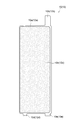
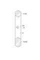
- FIG. 4 is a sectional view taken along the line IV-IV in FIG.
- FIG. 5 is a diagram showing the manufacturing process of the electrode.
- FIG. 6A, FIG. 6B, FIG. 6C and FIG. 6D are views showing a part of a lattice base material according to another embodiment.
- the lead storage battery 1 is, for example, a control valve type lead storage battery.
- the lead storage battery 1 includes an electrode group 3 and a case 5 that houses the electrode group 3.
- the electrode group 3 includes a plurality of positive electrodes 10, a plurality of negative electrodes 12, and a plurality of separators 13.
- the separator 13 is interposed between the positive electrode 10 and the negative electrode 12, and the positive electrode 10 and the negative electrode 12 are arranged alternately.
- the negative electrode 12 is arranged at the end of the positive electrode 10, the negative electrode 12, and the separator 13 in the arrangement direction (hereinafter, also simply referred to as “arrangement direction”).
- the positive electrode 10 has a positive electrode grid 10a.
- the positive electrode grid body 10a has a positive electrode current collector tab 10b.
- a positive electrode material 10c is provided on the positive electrode grid 10a.
- the positive electrode material 10c may include a positive electrode active material and an additive.
- the positive electrode active material is, for example, lead powder or the like.
- Examples of the additive include a carbon material, reinforcing short fibers and the like.
- the positive electrode grid body 10a is provided with convex portions 10d and 10e. The convex portions 10d and 10e are arranged at a predetermined interval and project outward from the positive electrode grid 10a.
- the negative electrode 12 has a negative electrode grid 12a.
- the negative electrode grid body 12a has a negative electrode current collecting tab 12b.
- a negative electrode material 12c is provided on the negative electrode grid 12a.
- the negative electrode material may include a negative electrode active material and an additive.
- the negative electrode active material is, for example, spongy lead. Examples of the additive include barium sulfate, a carbon material, and reinforcing short fibers.
- the negative electrode grid 12a is provided with projections 12d and 12e. The convex portions 12d and 12e are arranged at a predetermined interval and project outward from the negative electrode grid 12a.
- the separator 13 electronically insulates between the positive electrode 10 and the negative electrode 12 while allowing ions to pass therethrough, and has resistance to oxidizing property on the positive electrode 10 side and reducing property on the negative electrode 12 side.
- the material (material) of the separator 13 include glass fiber, resin, and inorganic material.
- Each of the positive electrodes 10 is electrically connected to the positive electrode terminal 14. Each positive electrode 10 and positive electrode terminal 14 are electrically connected by a positive electrode strap 17. Each of the negative electrodes 12 is electrically connected to the negative electrode terminal 16. Each negative electrode 12 and the negative electrode terminal 16 are electrically connected by a negative electrode strap 18.
- the case 5 has a main body 20 and a lid 22.
- the main body 20 is a box-shaped battery case.
- the main body 20 is made of a material such as polypropylene.
- the main body 20 is composed of four side surface portions 20a and a bottom portion (not shown).
- the lid 22 covers the opening of the main body 20.
- the lid 22 is provided with a first terminal portion 24 where the positive electrode terminal 14 is arranged, a second terminal portion 26 where the negative electrode terminal 16 is arranged, and a control valve 28.
- the grid body base material 30 forming the positive electrode grid body 10a and the negative electrode grid body 12a will be described.
- the positive electrode grid body 10a and the negative electrode grid body 12a are manufactured.
- the lattice base material 30 includes a frame portion 32, a lattice portion 34, and protruding portions 36a and 36b.
- the directions (X direction, Y direction) defined in FIG. 3 are used for description.
- the X direction corresponds to the first direction described in the claims.
- the Y direction corresponds to the second direction intersecting the first direction described in the claims.
- the frame portion 32 defines an internal space for holding the electrode material (the positive electrode material 10c and the negative electrode material 12c).
- the frame portion 32 is a rectangular frame. It has a pair of first frame bones 40a and 40b and a pair of second frame bones 42a and 42b. In the present embodiment, each of the pair of first frame bones 40a, 40b is shorter than each of the pair of second frame bones 42a, 42b.
- Each of the pair of first frame bones 40a, 40b faces each other in the X direction.
- Each of the pair of first frame bones 40a and 40b extends along the Y direction.
- Each of the pair of first frame bones 40a and 40b has a hexagonal prism shape. That is, the cross-sectional shape of the first frame bones 40a and 40b that intersects the Y direction is hexagonal.
- the first frame bone 40a and the first frame bone 40b may have the same thickness (cross-sectional area along the Y direction) or may have different thicknesses.
- Each of the pair of second frame bones 42a and 42b faces each other in the Y direction.
- Each of the pair of second frame bones 42a and 42b extends along the X direction.
- Each of the pair of second frame bones 42a and 42b has a hexagonal prism shape. That is, the cross-sectional shape of the second frame bones 42a and 42b that intersects the X direction is hexagonal (see FIG. 3).
- the second frame bone 42a is thicker than the second frame bone 42b.
- the first frame bones 40a, 40b and the second frame bones 42a, 42b are connected to each other at their ends.
- the lattice portion 34 is provided in the frame portion 32 and holds the electrode material (the positive electrode material 10c and the negative electrode material 12c).
- the lattice part 34 has a plurality of first lattice bones 44, a plurality of second lattice bones 46, and a third lattice bone 48.
- Each of the plurality of first lattice bones 44 extends along the X direction. That is, one end of the first lattice bone 44 is connected to the first frame bone 40a, and the other end of the first lattice bone 44 is connected to the first frame bone 40b.
- the plurality of first lattice bones 44 are arranged at predetermined intervals in the Y direction.
- Each of the plurality of first lattice bones 44 has a hexagonal prism shape. That is, the cross-sectional shape of the first lattice bones 44 that intersects each X direction is hexagonal.
- Each of the plurality of second lattice bones 46 extends along the Y direction. That is, one end of the second lattice bone 46 is connected to the second frame bone 42a, and the other end of the second lattice bone 46 is connected to the second frame bone 42b.
- the plurality of second lattice bones 46 are arranged at predetermined intervals in the X direction.
- Each of the plurality of second lattice bones 46 has a hexagonal prism shape. That is, the cross-sectional shape of each of the second lattice bones 46 that intersects the Y direction is hexagonal (see FIG. 4 ).
- the first lattice bone 44 and the second lattice bone 46 may have the same thickness or different thicknesses.
- the third lattice bone 48 extends along the X direction. That is, one end of the third lattice bone 48 is connected to the first frame bone 40a, and the other end of the third lattice bone 48 is connected to the first frame bone 40b. As shown in FIG. 4, the third lattice bone 48 has a triangular shape. That is, the cross-sectional shape of the third lattice bone 48 intersecting the Y direction has a triangular shape. As shown in FIG. 3, the third lattice bone 48 is arranged between the second frame bone 42b and the first lattice bone 44 arranged at the position closest to the second frame bone 42b in the Y direction. Has been done.
- the third lattice bone 48 is arranged in the central portion between the second frame bone 42b and the first lattice bone 44. That is, the distance between the third lattice bone 48 and the second frame bone 42b is equal to the distance between the third lattice bone 48 and the first lattice bone 44. As shown in FIG. 4, the third lattice bone 48 is arranged such that the one surface 48s is along the Y direction.
- the third lattice bone 48 is thinner than the first lattice bone 44 and the second lattice bone 46. That is, the cross-sectional area of the cross section of the third lattice bone 48 crossing the X direction is smaller than the cross-sectional area of the cross section of the first lattice bone 44 and the second lattice bone 46 along the X direction.
- the lattice portion 34 at least a part formed in the first region A1 on the other end side (the second frame bone 42b side) of the central portion in the extending direction (Y direction) of the first frame bones 40a, 40b.
- the opening areas of the openings O2, O3 of the openings are mainly formed in the second region A2 on the one end side (the second frame 42a side) with respect to the central portion in the extending direction of the first frame bones 40a, 40b. It is smaller than the opening area of the portion O1.
- the opening O1 is formed by the second frame bone 42a, the first lattice bone 44, and the second lattice bone 46.
- the opening O1 is formed by the first lattice bone 44 and the second lattice bone 46.
- the opening O1 has a rectangular shape.
- the opening O1 mainly formed in the second region A2 is formed by the second frame bone 42a, the first lattice bone 44 and the second lattice bone 46, or the first lattice bone 44 and the second lattice bone 46.
- the opening O2 is formed by the second frame bone 42b, the second lattice bone 46, and the third lattice bone 48.
- the opening O3 is formed by the first lattice bone 44, the second lattice bone 46, and the third lattice bone 48.
- the opening O2 and the opening O3 have a rectangular shape.
- the opening O2 and the opening O3 are continuously formed between the pair of first frame bones 40a and 40b.
- the opening area of the opening O2 is equal to the opening area of the opening O3.
- At least a part of the openings O2 and O3 formed in the first area A1 may broadly include that one opening O2 or opening O3 is formed in the first area A1. However, from the viewpoint of the action and effect obtained by forming the opening O2 or the opening O3, it is preferable that a plurality of the opening O2 or the opening O3 be formed.
- the opening area of the opening O2 and the opening area of the opening O3 are smaller than the opening area of the opening O1.
- the opening area of the opening O2 and the opening area of the opening O3 are, for example, 1/2 of the opening area of the opening O1.
- the opening area of the opening O4 formed by the second lattice bone 46 and the third lattice bone 48 is equal to the opening area of the opening O1.
- the protrusions 36a and 36b are provided on the pair of first frame bones 40a and 40b of the frame 32, respectively.
- the protrusions 36a and 36b are arranged at positions facing each other.
- the protruding portion 36a is provided on the first frame bone 40a.
- the protruding portion 36a is arranged on one end side in the extending direction of the first frame bone 40a. That is, the protruding portion 36a is arranged closer to the second frame bone 42a side of the frame portion 32 than the central portion in the extending direction of the first frame bone 40a.
- the projecting portion 36a projects outward from the first frame bone 40a along the X direction.
- the protruding portion 36b is provided on the first frame bone 40b.
- the protruding portion 36b is arranged on one end side in the extending direction of the first frame bone 40b. That is, the projecting portion 36b is arranged closer to the second frame bone 42a of the frame portion 32 than the central portion in the extending direction of the first frame bone 40a. The projecting portion 36b projects outward from the first frame bone 40b along the X direction.
- the protrusion 36b constitutes the protrusion 10e of the positive electrode 10 or the protrusion 12e of the negative electrode 12.
- a convex portion 50 is provided on the frame portion 32.
- the convex portion 50 is provided on the first frame bone 40b.
- the convex portion 50 is arranged on the other end side in the extending direction of the first frame bone 40b.
- the convex portion 50 is arranged in the Y direction with a predetermined distance from the protruding portion 36b.
- the convex portion 50 projects outward from the first frame bone 40b along the X direction.
- the convex portion 50 constitutes the convex portion 10d of the positive electrode 10 and the convex portion 12d of the negative electrode 12.
- the manufacturing method of the lead storage battery 1 includes an electrode manufacturing process and an assembly process.
- the electrode manufacturing process is a process of obtaining the electrodes (the positive electrode 10 and the negative electrode 12), and includes, for example, a preparation process, a filling process, a pressing process, a carrying process, an aging process, a drying process, and a cutting process.
- the number of grid base materials 30 to be prepared is determined according to the number of electrodes to be manufactured.
- the lattice base material 30 is produced by casting, for example.
- a filling step of filling the grid material base material 30 with the electrode material paste P is performed.
- the electrode material paste P is filled into the grid body base material 30 placed horizontally on a conveyor (not shown) by a filling machine (not shown).
- the lattice base material 30 is placed on the conveyor so that one surface 48s (see FIG. 4) of the third lattice bone 48 of the lattice portion 34 faces the filling machine (the supply port side of the electrode material paste P).
- a pressing step of pressing the electrode material paste P with which the grid base material 30 is filled is performed.
- pressure is applied to the electrode material paste P by sandwiching the grid body base material 30 in the vertical direction with a press roll (not shown).
- the electrode material paste P is filled from the filling side where the electrode material paste P is filled to the side opposite to the filling side in the grid portion 34 of the grid body base material 30, and the filling property of the electrode material paste P is enhanced. ..
- the electrode material paste P filled from the one surface 48 s side wraps around to the other surface and is filled. Further, the thickness of the electrode material paste P filled in the grid base material 30 is made uniform, and the electrode material paste P is physically adhered to the grid portion 34.
- the transport device 100 includes a pair of drive pulleys 102a and 102b, a pair of transport belts 104a and 104b, and a guide unit 106.
- the conveyor belt 104a is stretched around the drive pulley 102a.
- the conveyor belt 104b is stretched around the drive pulley 102b.
- the pair of conveyor belts 104a and 104b are arranged at a predetermined interval. Specifically, the pair of conveyor belts 104a and 104b are arranged below the pair of protrusions 36a and 36b of the lattice base material 30.
- the guide unit 106 is arranged on the upstream side in the carrying direction of the carrying apparatus 100.
- the guide portion 106 has an inclined surface 106a that is inclined downward from the upstream side to the downstream side in the transport direction.
- the grid base material 30 is carried while being supported by the pair of carrying belts 104a and 104b. Specifically, the protrusions 36a of the lattice base material 30 are supported by the conveyor belt 104a, and the protrusions 36b are supported by the conveyor belt 104b.
- the grid body base material 30 shifts from the horizontal state to the suspended state, and then is transported in the suspended state.
- the grid body base material 30 filled with the electrode material paste P is loaded into the transport device 100 in a horizontally placed horizontal state.
- the second frame bones 42b of the lattice base material 30 carried into the transport device 100 abut the inclined surface 106a of the guide portion 106.
- the lattice base material 30 slides on the guide portion 106 as it is conveyed by the conveyor belts 104a and 104b.
- the lattice base material 30 is gradually moved from the horizontal state to the suspended state by the guide of the inclined surface 106a of the guide portion 106.
- an aging step of aging the grid body base material 30 filled with the electrode material paste P is performed.
- a drying step of drying the grid body base material 30 filled with the electrode material paste P is performed.
- the lattice base material 30 is aged and dried in a suspended state in which the pair of protrusions 36a and 36b are supported by a support member (not shown).
- a cutting process for cutting the lattice base material 30 is performed.
- the protrusions 36b of the lattice base material 30 are cut to form the protrusions 10e and 12e.
- a rotary cutter for example, is used to cut the lattice base material 30.
- polishing for removing the electrode material paste P deposited on the frame 32 may be performed.
- the assembly process of obtaining the lead storage battery 1 by assembling the components including the electrode plate is performed.
- unformed positive electrodes and unformed negative electrodes are alternately laminated with the separators 13 interposed therebetween, and the positive electrode current collector tabs 10b of the positive electrode grid body 10a are connected (welded) together by the positive electrode straps 17 and the negative electrode grids are formed.
- the electrode group 3 is obtained by connecting (welding) the negative electrode current collecting tabs 12b of the body 12a to each other with the negative electrode strap 18. Then, by accommodating the electrode group 3 in the main body 20 of the case 5, an unformed battery is manufactured.
- a direct current is passed to perform battery case formation, and the specific gravity of the formed electrolytic solution is adjusted to an appropriate specific gravity. From the above, the lead storage battery 1 is obtained.
- the opening areas of at least some of the openings O2 and O3 formed in the first area A1 are mainly formed in the second area A2. It is smaller than the opening area of the opening O1.
- the first region A1 is a portion of the lattice portion 34 that is distant from the position where the pair of protrusions 36a and 36b are provided.
- the holding force of the electrode material paste P held in the opening is improved. Therefore, in the grid base material 30, when the electrode material paste P is filled, the electrode material paste P is retained in the first area A1, that is, the area away from the position where the pair of protrusions 36a and 36b are provided. it can.
- the opening area of the opening O2 formed including the one second frame bone 42b is smaller than the opening area of the opening O1 mainly formed in the second region A2. Is also small.
- the lattice base material 30 shakes. When moving, the moment of inertia becomes the largest.
- the electrode material paste P can be more reliably prevented from falling off.
- the lattice portion 34 has a plurality of first lattice bones 44, a plurality of second lattice bones 46, and a third lattice bone 48.
- the third lattice bone 48 forms at least part of the openings O2 and O3 formed in the first region A1.
- the openings O2, O3 having a small opening area can be formed.
- the third lattice bone 48 is arranged between the second frame bone 42b and the first lattice bone 44 arranged at the position closest to the second frame bone 42b. And extends along the X direction.
- the opening areas of the openings O2 and O3 formed at positions apart from the pair of protrusions 36a and 36b are formed small between the pair of first frame bones 40a and 40b. Therefore, in the grid body base material 30, the electrode material paste P can be more reliably prevented from falling off. Further, since the opening areas of the openings (openings O1 and O4) of other portions are secured, the amount of the electrode material paste P held can also be secured. Therefore, it is possible to suppress the deterioration of the characteristics of the electrode formed by the lattice base material 30.
- the cross section of the third lattice bone 48 has a triangular shape.
- the electrode material paste P is filled from the one surface 48s side of the third lattice bone 48 to the other surface side of the third lattice bone 48. You can also get around. Therefore, the electrode material paste P can be filled with high density in the openings O2, O3 formed including the third lattice bones 48. Therefore, the grid body base material 30 can suppress the electrode material paste P from falling off.
- the third lattice bone 48 is thinner than the first lattice bone 44 and the second lattice bone 46.
- the pair of first frame bones 40a and 40b is shorter than the pair of second frame bones 42a and 42b, respectively. did.
- each of the pair of first frame bones 40a and 40b may be longer than each of the pair of second frame bones 42a and 42b, or may have the same length.
- the form in which the openings O2 and O3 each having a smaller opening area than the other openings O1 and O4 are formed in the first region A1 of the lattice portion 34 has been described as an example.
- an opening having an opening area equivalent to that of the openings O2 and O3 may be further formed.
- the area of all the openings of the first region A1 may be smaller than the area of the openings of the second region A2.
- the opening O2 and O3 are described as an example in which the openings O2 and O3 are continuously formed between the pair of first frame bones 40a and 40.
- the openings O2 and O3 may be intermittently formed between the pair of first frame bones 40a and 40.
- first frame bones 40a, 40b and the second frame bones 42a, 42b of the frame portion 32, and the first lattice bones 44 and the second lattice bones 46 of the lattice portion 34 are hexagonal columns.
- first frame bones 40a and 40b and the second frame bones 42a and 42b of the frame portion 32, and the first lattice bones 44 and the second lattice bones 46 of the lattice portion 34 have other shapes (columns, polygonal columns, etc.). ).
- the third lattice bone 48 of the lattice portion 34 has a triangular prism shape as an example.
- the third lattice bone 48 may have other shapes.
- the openings O2 and O3 having a rectangular shape are formed in the first region A1 by one third lattice bone 48 .
- the shape of the openings (corresponding to the openings O2 and O3) and the size of the opening area formed in the first area A1 are not limited to this.
- the opening may be formed by the third lattice bones 48a and 48b which are arranged at a predetermined angle with respect to the X direction and the Y direction and which are arranged to intersect each other. Good.
- the opening area of each opening is, for example, about 1/4 of the opening area of the opening O1.
- the opening may be formed by the third lattice bone 48c arranged at a predetermined angle with respect to the X direction and the Y direction.
- the opening area of each opening is, for example, about 1/2 of the opening area of the opening O1.
- the opening may be formed by the third lattice bone 48d extending along the Y direction.
- each opening is, for example, about 1/2 of the opening area of the opening O1.
- the opening may be formed by the third lattice bone 48e extending along the X direction and the third lattice bone 48f extending along the Y direction.
- the opening area of each opening is, for example, about 1/4 of the opening area of the opening O1.
- the present invention may appropriately combine the contents described as the above-mentioned embodiment and other modifications.
Landscapes
- Chemical & Material Sciences (AREA)
- Chemical Kinetics & Catalysis (AREA)
- Electrochemistry (AREA)
- General Chemical & Material Sciences (AREA)
- Cell Electrode Carriers And Collectors (AREA)
Abstract
Description
図1に示されるように、鉛蓄電池1は、例えば、制御弁式鉛蓄電池である。鉛蓄電池1は、電極群3と、電極群3を収容するケース5と、を備えている。
続いて、正極格子体10a及び負極格子体12aを構成する格子体基材30について説明する。格子体基材30を加工することにより、正極格子体10a及び負極格子体12aが製造される。図3に示されるように、格子体基材30は、枠部32と、格子部34と、突出部36a,36bと、を備えている。以下の説明においては、図3で規定する方向(X方向、Y方向)を説明に用いる。X方向は、請求の範囲に記載の、第一方向に対応する。Y方向は、請求項の範囲に記載の、第一方向に交差する第二方向に対応する。
次に、鉛蓄電池1の製造方法について説明する。鉛蓄電池1の製造方法は、電極製造工程と、組立工程と、を備えている。電極製造工程は、電極(正極10及び負極12)を得る工程であって、例えば、準備工程、充填工程、プレス工程、搬送工程、熟成工程、乾燥工程、及び切断工程を含む。
Claims (8)
- 第一方向に対向して配置される一対の第一枠骨と、前記第一方向と交差する第二方向に対向して配置される一対の第二枠骨と、を有している枠部と、
前記枠部内に配置されており、複数の開口部が形成されている格子部と、
一対の前記第一枠骨のそれぞれに設けられており、前記第一枠骨の延在方向の一端部側に配置されている一対の突出部と、を備え、
前記格子部において、前記第一枠骨の前記延在方向の中央部よりも他端部側の第一領域に形成されている少なくとも一部の前記開口部の開口面積は、前記第一枠骨の前記延在方向の前記中央部よりも前記一端部側の第二領域に主として形成されている前記開口部の開口面積よりも小さい、格子体基材。 - 前記他端部側に配置されている一方の前記第二枠骨を含んで形成さている前記開口部の開口面積は、前記第二領域に主として形成されている前記開口部の開口面積よりも小さい、請求項1に記載の格子体基材。
- 前記格子部は、
前記第一方向に沿って延在していると共に前記第二方向において所定の間隔をあけて配置されている複数の第一格子骨と、
前記第二方向に沿って延在していると共に前記第一方向において所定の間隔をあけて配置されている複数の第二格子骨と、
一又は複数の第三格子骨と、を有しており、
前記第三格子骨は、前記第一領域に形成されている少なくとも一部の前記開口部を形成している、請求項1又は2に記載の格子体基材。 - 前記第三格子骨は、前記他端部側に配置されている一方の前記第二枠骨と当該第二枠骨に最も近い位置に配置されている前記第一格子骨との間に配置されており、前記第一方向に沿って延在している、請求項3に記載の格子体基材。
- 一又は複数の前記第三格子骨の前記第二方向に沿った断面は、三角形状を呈している、請求項3又は4に記載の格子体基材。
- 前記第三格子骨は、前記第一格子骨及び前記第二格子骨よりも細い、請求項3~5のいずれか一項に記載の格子体基材。
- 請求項1~6の何れか一項記載の格子体基材から形成される格子体と、
前記格子体に保持されている電極材と、を備える、電極。 - 請求項1~6の何れか一項記載の格子体基材から形成される格子体と、前記格子体に保持されている正極材とを有する正極と、
前記格子体と、前記格子体に保持されている負極材とを有する負極と、
前記正極と前記負極との間に配置されたセパレータと、を備える、鉛蓄電池。
Priority Applications (3)
| Application Number | Priority Date | Filing Date | Title |
|---|---|---|---|
| CN201980093861.XA CN113544883A (zh) | 2019-01-16 | 2019-01-16 | 格子体基材、电极及铅蓄电池 |
| PCT/JP2019/001123 WO2020148836A1 (ja) | 2019-01-16 | 2019-01-16 | 格子体基材、電極及び鉛蓄電池 |
| JP2020566023A JPWO2020148836A1 (ja) | 2019-01-16 | 2019-01-16 | 格子体基材、電極及び鉛蓄電池 |
Applications Claiming Priority (1)
| Application Number | Priority Date | Filing Date | Title |
|---|---|---|---|
| PCT/JP2019/001123 WO2020148836A1 (ja) | 2019-01-16 | 2019-01-16 | 格子体基材、電極及び鉛蓄電池 |
Publications (1)
| Publication Number | Publication Date |
|---|---|
| WO2020148836A1 true WO2020148836A1 (ja) | 2020-07-23 |
Family
ID=71613195
Family Applications (1)
| Application Number | Title | Priority Date | Filing Date |
|---|---|---|---|
| PCT/JP2019/001123 Ceased WO2020148836A1 (ja) | 2019-01-16 | 2019-01-16 | 格子体基材、電極及び鉛蓄電池 |
Country Status (3)
| Country | Link |
|---|---|
| JP (1) | JPWO2020148836A1 (ja) |
| CN (1) | CN113544883A (ja) |
| WO (1) | WO2020148836A1 (ja) |
Citations (7)
| Publication number | Priority date | Publication date | Assignee | Title |
|---|---|---|---|---|
| JPS5116415Y1 (ja) * | 1970-12-16 | 1976-04-30 | ||
| JPH09134727A (ja) * | 1995-11-09 | 1997-05-20 | Matsushita Electric Ind Co Ltd | 鉛蓄電池用極板の格子体製造法 |
| JP2010218992A (ja) * | 2009-03-19 | 2010-09-30 | Furukawa Battery Co Ltd:The | 鉛蓄電池用格子基板 |
| JP2012089511A (ja) * | 2011-12-15 | 2012-05-10 | Shin Kobe Electric Mach Co Ltd | 鉛蓄電池 |
| JP2013176776A (ja) * | 2012-02-28 | 2013-09-09 | Shin Kobe Electric Mach Co Ltd | 鉛蓄電池極板の格子基板鋳造用金型 |
| JP2017016943A (ja) * | 2015-07-03 | 2017-01-19 | 日立化成株式会社 | 鉛蓄電池用複合集電体 |
| JP2018073789A (ja) * | 2016-11-04 | 2018-05-10 | 株式会社Gsユアサ | 鉛蓄電池 |
Family Cites Families (5)
| Publication number | Priority date | Publication date | Assignee | Title |
|---|---|---|---|---|
| JP2001185207A (ja) * | 1999-12-27 | 2001-07-06 | Yuasa Corp | 制御弁式鉛蓄電池 |
| JP2004220927A (ja) * | 2003-01-15 | 2004-08-05 | Matsushita Electric Ind Co Ltd | 鉛蓄電池 |
| JP4884748B2 (ja) * | 2005-10-31 | 2012-02-29 | 古河電池株式会社 | 鉛蓄電池用格子基板 |
| CN102640334B (zh) * | 2010-10-18 | 2014-09-17 | 新神户电机株式会社 | 铅蓄电池 |
| JP7005945B2 (ja) * | 2017-06-06 | 2022-01-24 | 株式会社Gsユアサ | 鉛蓄電池用電極格子 |
-
2019
- 2019-01-16 WO PCT/JP2019/001123 patent/WO2020148836A1/ja not_active Ceased
- 2019-01-16 CN CN201980093861.XA patent/CN113544883A/zh active Pending
- 2019-01-16 JP JP2020566023A patent/JPWO2020148836A1/ja active Pending
Patent Citations (7)
| Publication number | Priority date | Publication date | Assignee | Title |
|---|---|---|---|---|
| JPS5116415Y1 (ja) * | 1970-12-16 | 1976-04-30 | ||
| JPH09134727A (ja) * | 1995-11-09 | 1997-05-20 | Matsushita Electric Ind Co Ltd | 鉛蓄電池用極板の格子体製造法 |
| JP2010218992A (ja) * | 2009-03-19 | 2010-09-30 | Furukawa Battery Co Ltd:The | 鉛蓄電池用格子基板 |
| JP2012089511A (ja) * | 2011-12-15 | 2012-05-10 | Shin Kobe Electric Mach Co Ltd | 鉛蓄電池 |
| JP2013176776A (ja) * | 2012-02-28 | 2013-09-09 | Shin Kobe Electric Mach Co Ltd | 鉛蓄電池極板の格子基板鋳造用金型 |
| JP2017016943A (ja) * | 2015-07-03 | 2017-01-19 | 日立化成株式会社 | 鉛蓄電池用複合集電体 |
| JP2018073789A (ja) * | 2016-11-04 | 2018-05-10 | 株式会社Gsユアサ | 鉛蓄電池 |
Also Published As
| Publication number | Publication date |
|---|---|
| JPWO2020148836A1 (ja) | 2021-10-28 |
| CN113544883A (zh) | 2021-10-22 |
Similar Documents
| Publication | Publication Date | Title |
|---|---|---|
| JP6638795B2 (ja) | 鉛蓄電池及びその製造方法 | |
| CN108352576B (zh) | 电极组装体以及电极组装体的制造方法 | |
| US5512065A (en) | Methods for assembling lead-acid batteries | |
| US4215186A (en) | Battery plate separator and battery containing the same | |
| KR20180129115A (ko) | 원통형 셀 연결 분리형 버스바와 이를 이용한 배터리 모듈 및 제조 방법 | |
| KR102689862B1 (ko) | 이차 전지 | |
| WO2014103594A1 (ja) | 電気デバイス、電気デバイスのセパレータ接合装置およびその接合方法 | |
| US9722215B2 (en) | Cylindrical battery | |
| JP2012009210A (ja) | 電池 | |
| CN104412415A (zh) | 制造扁平型非水二次电池的方法 | |
| WO2020148836A1 (ja) | 格子体基材、電極及び鉛蓄電池 | |
| EP2811546B1 (en) | Lead-acid storage battery | |
| JP2021026983A (ja) | 蓄電装置 | |
| JP2019057445A (ja) | 蓄電装置 | |
| JPH031455A (ja) | 密閉角型アルカリ蓄電池 | |
| JP7241054B2 (ja) | 二次電池 | |
| WO2020162152A1 (ja) | 格子体基材、電極及び鉛蓄電池 | |
| JP2019133845A (ja) | 鉛蓄電池 | |
| JP3032216B2 (ja) | 鉛蓄電池用複合極板 | |
| CN117397076A (zh) | 电极组件及其制造设备和方法、包括电极组件的圆柱形电池和包括其的电池组和车辆 | |
| JP2007018833A (ja) | 蓄電池の製造方法 | |
| JP2015185478A (ja) | 密閉型鉛蓄電池 | |
| JP7731884B2 (ja) | 電池用セパレータ、蓄電池、組電池及び電動車 | |
| JPH0763012B2 (ja) | 金属被覆を備えた平板電極及びその製造方法 | |
| JP2014002858A (ja) | 電極収納セパレータ及び蓄電装置 |
Legal Events
| Date | Code | Title | Description |
|---|---|---|---|
| 121 | Ep: the epo has been informed by wipo that ep was designated in this application |
Ref document number: 19910029 Country of ref document: EP Kind code of ref document: A1 |
|
| ENP | Entry into the national phase |
Ref document number: 2020566023 Country of ref document: JP Kind code of ref document: A |
|
| NENP | Non-entry into the national phase |
Ref country code: DE |
|
| 32PN | Ep: public notification in the ep bulletin as address of the adressee cannot be established |
Free format text: NOTING OF LOSS OF RIGHTS PURSUANT TO RULE 112(1) EPC (EPO FORM 1205A DATED 12-10-2021) |
|
| 122 | Ep: pct application non-entry in european phase |
Ref document number: 19910029 Country of ref document: EP Kind code of ref document: A1 |