WO2020145390A1 - 線材コイル製造ラインにおけるリフォーミングタブの制御方法及び装置 - Google Patents
線材コイル製造ラインにおけるリフォーミングタブの制御方法及び装置 Download PDFInfo
- Publication number
- WO2020145390A1 WO2020145390A1 PCT/JP2020/000691 JP2020000691W WO2020145390A1 WO 2020145390 A1 WO2020145390 A1 WO 2020145390A1 JP 2020000691 W JP2020000691 W JP 2020000691W WO 2020145390 A1 WO2020145390 A1 WO 2020145390A1
- Authority
- WO
- WIPO (PCT)
- Prior art keywords
- coil
- wire rod
- rear end
- nose cone
- iris
- Prior art date
- Legal status (The legal status is an assumption and is not a legal conclusion. Google has not performed a legal analysis and makes no representation as to the accuracy of the status listed.)
- Ceased
Links
Images



Classifications
-
- B—PERFORMING OPERATIONS; TRANSPORTING
- B21—MECHANICAL METAL-WORKING WITHOUT ESSENTIALLY REMOVING MATERIAL; PUNCHING METAL
- B21C—MANUFACTURE OF METAL SHEETS, WIRE, RODS, TUBES, PROFILES OR LIKE SEMI-MANUFACTURED PRODUCTS OTHERWISE THAN BY ROLLING; AUXILIARY OPERATIONS USED IN CONNECTION WITH METAL-WORKING WITHOUT ESSENTIALLY REMOVING MATERIAL
- B21C47/00—Winding-up, coiling or winding-off metal wire, metal band or other flexible metal material characterised by features relevant to metal processing only
- B21C47/02—Winding-up or coiling
- B21C47/10—Winding-up or coiling by means of a moving guide
- B21C47/14—Winding-up or coiling by means of a moving guide by means of a rotating guide, e.g. laying the material around a stationary reel or drum
-
- B—PERFORMING OPERATIONS; TRANSPORTING
- B21—MECHANICAL METAL-WORKING WITHOUT ESSENTIALLY REMOVING MATERIAL; PUNCHING METAL
- B21C—MANUFACTURE OF METAL SHEETS, WIRE, RODS, TUBES, PROFILES OR LIKE SEMI-MANUFACTURED PRODUCTS OTHERWISE THAN BY ROLLING; AUXILIARY OPERATIONS USED IN CONNECTION WITH METAL-WORKING WITHOUT ESSENTIALLY REMOVING MATERIAL
- B21C47/00—Winding-up, coiling or winding-off metal wire, metal band or other flexible metal material characterised by features relevant to metal processing only
- B21C47/26—Special arrangements with regard to simultaneous or subsequent treatment of the material
-
- B—PERFORMING OPERATIONS; TRANSPORTING
- B65—CONVEYING; PACKING; STORING; HANDLING THIN OR FILAMENTARY MATERIAL
- B65H—HANDLING THIN OR FILAMENTARY MATERIAL, e.g. SHEETS, WEBS, CABLES
- B65H54/00—Winding, coiling, or depositing filamentary material
- B65H54/76—Depositing materials in cans or receptacles
Definitions
- the present invention relates to a method and an apparatus for controlling a reforming tab in a wire rod coil production line, and more particularly to a method and an apparatus for controlling a timing when a coil plate in which wire rod coils of a reforming tab are integrated descends.
- a wire rod rolled by a wire rod rolling mill is formed into a continuous ring shape by a laying head to form a wire rod coil, which is unrolled and conveyed on a conveyor.
- the wire rod coils conveyed by the conveyor are accumulated by a coil focusing device (hereinafter referred to as reforming tab) arranged at the end of the conveyor.
- reforming tab is a nose cone for positioning the wire rod coil by passing the wire rod coil conveyed from the conveyor, and is arranged so that it can be moved forward and backward toward the lower outer circumference of the nose cone to temporarily store the wire rod coil.
- An apparatus that includes an iris and a coil plate that is vertically movable to a position below the iris and that accumulates wire rod coils (see, for example, Patent Document 2).
- the iris of the reforming tab is composed of a plurality of iris arms arranged at a predetermined interval in the circumferential direction surrounding the lower outer circumference of the nose cone, and the plurality of iris arms advance toward the lower outer circumference of the nose cone. Then, the tip of the iris arm enters into the nose cone hole provided on the lower outer circumference of the nose cone.
- the iris is closed, and the wire rod coil passing through the nose cone is temporarily stored by the iris.
- the tip comes out of the nose cone hole and the iris arm retracts from the nose cone the iris opening operation is performed, and the coil plate that has risen to the position below the iris, the wire coil temporarily stored in the iris. Are transferred.
- the wire rod coil is accumulated on the coil plate up to the rear end of the coil, and when the work of assembling the wire rod coil is completed, the lowering operation of the coil plate is performed to move the wire rod coil downward to carry it out of the line. To go.
- Patent Document 1 is a technique for setting the timing when cutting the ends of the wire rod coils integrated by a cutting machine provided in the reforming tab
- Patent Document 2 is applicable to wire rod coils having a plurality of outer diameters.
- Patent Documents 1 and 2 cannot prevent the rear end of the coil from being caught in the nose cone hole when the coil plate collects the wire rod coils.
- An object of the present invention is to provide a method and apparatus for controlling a reforming tab in a wire rod coil production line that can be manufactured.
- a method of controlling a reforming tab in a wire rod coil production line is a method of controlling a reforming tab in which wire rod coils conveyed from upstream equipment of a wire rod coil production line are integrated.
- the reforming tab consists of a nose cone that positions the wire rod coil that has been conveyed from above to position the wire rod coil, an iris that can be moved forward and backward toward the outer periphery of the lower side of the nose cone, and a lower portion of the iris.
- a coil plate that is arranged to be movable up and down to a position and that accumulates wire rod coils.
- the iris temporarily stores the wire rod coil by performing the closing operation to enter the nose cone hole provided in the nose cone, and transfers the wire rod coil storage to the coil plate by performing the opening operation to leave the nose cone hole. ..
- the method of the present invention continues to be integrated on the coil plate, and the coil rear end position calculating step for calculating the coil rear end position of the wire rod coil manufactured in the upstream equipment, and the coil rear end position is the reforming tab.
- An arrival time calculation step for calculating the arrival time at which the arrival time reaches the coil plate, and a coil plate lowering control step for lowering the coil plate when the arrival time is reached.
- the control device of the reforming tab in the wire rod coil production line is the control device of the reforming tab that integrates the wire rod coils transferred from the upstream equipment of the wire rod coil production line.
- the reforming tab consists of a nose cone that positions the wire rod coil that has been conveyed from above to position the wire rod coil, an iris that can be moved forward and backward toward the outer periphery of the lower side of the nose cone, and a lower portion of the iris.
- a coil plate that is arranged to be movable up and down to a position and that accumulates wire rod coils.
- the iris temporarily stores the wire rod coil by performing a closing operation to enter the nose cone hole provided in the nose cone, and transfers the wire rod coil reserve to the coil plate by performing an opening operation to leave the nose cone hole. ing.
- the device of the present invention continues to be integrated on the coil plate, and the coil rear end position calculation unit that calculates the coil rear end position of the wire rod coil manufactured in the upstream equipment and the coil rear end position is the reforming tab.
- An arrival time calculation unit that calculates the arrival time at which the arrival time reaches the coil plate, and a coil plate lowering control unit that lowers the coil plate when the arrival time is reached.
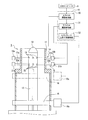
- the wire rod coil production line 1 of the present embodiment includes a wire rod rolling machine 2 that rolls a wire rod W, a raying head 3 that forms the wire rod W rolled by the wire rod rolling machine 2 into a ring shape, and forms a wire rod coil C W.
- the conveyor 4 that expands and conveys the wire rod coil C W formed by the laying head 3, the reforming tab 5 that is arranged at the end of the conveyor 4 and accumulates the wire rod coil C W , and the wire rod rolling mill 2
- a host computer 6 for controlling the drive of the conveyor 4 and the reforming tab 5, and a reforming tab controller 10 for controlling the drive of the reforming tab 5 by inputting data from the host computer 6.
- C W1 the wire rod coil manufactured in the preceding step
- C W2 the wire rod coil manufactured in the next step
- the wire rod rolling machine 2 is provided with a heat lump detector 7 (referred to as Hot Metal Detector: HMD7).
- HMD7 Hot Metal Detector
- the change in the detected value of the HMD 7 is output to the host computer 6.
- the host computer 6 calculates the tail end position of the wire W based on the change in the detection value of the HMD 7, and outputs information on the tail end position of the wire W to the forming tab controller 10.
- a pulse oscillator 9 is connected to a motor 8 that drives the conveyor 4, and output pulses generated by the pulse oscillator 9 based on the drive of the motor 8 are output to the host computer 6.
- the host computer 6 calculates the transport speed of the conveyor 4 based on the output pulse generated by the pulse transmitter 9, and outputs the information of the transport speed of the conveyor 4 to the reforming tab controller 10.
- FIG. 2 shows the reforming tab 5 of this embodiment and a reforming tab controller 10 that is connected to the host computer 6 to control the drive of the reforming tab 5.
- the reforming tab 5 is supported by the chamber 11 having a cylindrical shape with an open top, a mandrel 12 standing upright in the chamber 11, a nose cone 13 coaxially connected to the upper end of the mandrel, and the chamber 11. It is provided with an upper iris 14 and a lower iris 15 which are moved forward and backward toward the nose cone 13 and a coil plate 16 which is supported by the chamber 11 and moves vertically.
- the upper iris 14 is arranged at a predetermined interval in the circumferential direction of the chamber 11, and is arranged so as to be capable of advancing and retracting toward the lower outer circumference of the nose cone 13, and each upper iris arm 17a. , 17b..., and a plurality of upper iris drive units 18a, 18b.
- the upper iris 14 By performing the closing operation, temporarily stores the wire rod coil C W2 which will be manufactured in the next process and then integrated in the coil plate 16.
- the lower iris 15 is also arranged below the chamber 11 in the circumferential direction at a predetermined interval with respect to the upper iris 14. , 20b, and a plurality of lower iris drive units 21a, 21b,... For moving forward and backward the respective lower iris arms 20a, 20b. Further, a lower nose cone hole 22 into which the tips of the lower iris arms 20 a, 20 b, etc. enter when the plurality of lower iris arms 20 a, 20 b... By performing the closing operation, the lower iris 15 temporarily stores the wire rod coil C W1 accumulated in the preceding step until the coil plate 16 moves up to a position below the lower iris 15.
- the coil plate 16 is a device that is guided by the chamber 11 so as to be vertically movable and is moved up and down by driving the coil plate drive unit 16a in the forward and reverse directions.
- the coil plate drive unit 16a is a device capable of moving the coil plate 16 in the vertical direction with high speed/low speed specifications.
- the reforming tab control unit 10 includes an upper iris opening/closing control unit 30, a lower iris opening/closing control unit 31, and a coil plate raising/lowering control unit 32.
- the upper iris opening/closing control unit 30 outputs a closing operation signal to the plurality of upper iris driving units 18a, 18b..., By driving the plurality of upper iris driving units 18a, 18b. Are advanced toward the nose cone 13 and their tips are inserted into the upper nose cone hole 19. Further, by outputting an opening operation signal to the plurality of upper iris driving portions 18a, 18b... By driving the plurality of upper iris driving portions 18a, 18b... In the opposite direction, the plurality of upper iris arms 17a, 17b. Move back from 13.
- the lower iris opening/closing control unit 31 outputs a closing operation signal to the plurality of lower iris driving units 21a, 21b..., By driving the plurality of lower iris driving units 21a, 21b. Are advanced toward the nose cone 13 and their tips are inserted into the lower nose cone hole 22. Further, by outputting an opening operation signal to the plurality of lower iris driving units 21a, 21b..., The plurality of lower iris arms 20a, 20b. Move back from 13.
- the coil plate raising/lowering control unit 32 performs a coil plate raising control process by outputting a driving signal for raising movement to the coil plate driving unit 16a to raise the coil plate 16.
- a downward drive signal is output to the coil plate drive unit 16a to lower the coil plate 16, thereby lowering the coil plate 16 to the carry-out position.
- step ST1 information on the tail end position of the wire rod W that has passed through the wire rod rolling machine 2 stored in the host computer 6 is obtained.
- step ST2 information on the transport speed of the conveyor 4 stored in the host computer 6 is obtained.
- step ST3 the coil rear end Cb side of the wire rod coil CW 1 accumulated in the coil plate 16 in the current step is reformed based on the information on the tail end position of the wire rod W and the transport speed of the conveyor 4.
- a time (arrival time) Hb at which the tab 5 is reached is predicted and calculated.
- step ST4 it is determined whether or not the current time reaches the arrival time Hb. If the current time reaches the arrival time Hb, the process proceeds to step ST5, and the current time still reaches the arrival time Hb. If not, the coil plate lowering control process ends. In step ST5, a downward drive signal is output to the coil plate drive unit 16a at a high speed so that the coil plate 16 is rapidly lowered to the carry-out position.
- the coil plate lowering control process performed by the coil plate raising/lowering control unit 32 shown in the flowchart S of FIG. 3 is repeatedly executed until the current time reaches the arrival time Hb.
- the coil rear end position calculation step described in the present invention corresponds to step ST1, step ST2, and step ST3 in FIG. 3, and the arrival time calculation step described in the present invention corresponds to step ST3 in FIG.
- the coil plate lowering control step described in the present invention corresponds to step ST4 and step ST5 in FIG.
- the coil rear end position calculation unit described in the invention of the present application corresponds to step ST1, step ST2, step ST3 and the coil plate raising/lowering control unit 31 of FIG. 3, and the arrival time described in the invention of the present application.
- the calculation unit corresponds to the step ST3 and the coil plate raising/lowering control unit 31 of FIG. 3, and the coil plate lowering control unit described in the present invention is the step ST4, the step ST5 and the coil plate raising/lowering of FIG. It corresponds to the control unit 31.
- the iris described in the present invention corresponds to the upper iris 15 and the lower iris 16, and the nose cone hole described in the present invention corresponds to the upper nose cone hole 19 and the lower nose cone hole 22. There is.
- the upper iris 14 is opened by the control of the upper iris opening/closing control unit 30 until the coil plate 16 rises to the position where the wire rod coil C W1 is integrated, and the lower iris opening/closing control is performed.
- the wire coil C W1 is transferred from the upper iris 14 to the lower iris 15 by performing the closing operation of the lower iris 15 under the control of the unit 31.
- the lower iris 15 is opened by the control of the lower iris opening/closing control unit 31, and is stored in the lower iris 15.
- the wire rod coil C W1 is transferred to the coil plate 16, and the wire rod coil C W1 is accumulated on the coil plate 16.
- the coil plate raising/lowering control unit 32 resets the coil rear end Cb side of the wire rod coil CW 1.
- the arrival time Hb to reach the forming tab 5 is calculated (step ST3 in FIG. 3).
- the coil plate up/down control unit 32 outputs a downward drive signal to the coil plate drive unit 16a with high speed specifications (step ST5 in FIG. 3). ..
- the coil plate 16 in which the wire rod coils C W1 are integrated performs a rapid descent operation as shown in FIG. 7.
- the speed of the coil plate 16 is in the range of 50 mm/sec to 700 mm/sec, and the descending distance is about 3 m.
- the coil rear end Cb of the wire rod coil C W1 reaches the reforming tab 5 at a position above the nose cone 13.
- the coil rear end Cb passes through the upper nose cone hole 19 and the lower nose cone hole 22 formed in the nose cone 13 while increasing the speed by the coil plate 16 performing a rapid descent operation. Therefore, there is no possibility that the coil rear end Cb enters the upper nose cone hole 19 and the lower nose cone hole 22 and is caught. Then, the coil plate 16 that has performed the descent operation descends to the carry-out position, and the wire rod coil CW on the coil plate 16 that has completed the integration is carried out to the outside.
- the coil plate 16 since the coil rear end Cb of the wire rod coil C W1 reaches the reforming tab 5 at a position above the nose cone 13, the coil plate 16 performs the descent operation.
- the end Cb passes through the upper nose cone hole 19 while increasing the speed with respect to the upper nose cone hole 19 and the lower nose cone hole 22 formed in the nose cone 13 by the coil plate 16 performing the descent operation. Also, there is no danger of getting caught in the lower nose cone hole 22. Therefore, it becomes unnecessary monitoring of workers upon completion of accumulation of the wire coil C W1 to the coil plate 16 of the reforming tab 5, it is possible to improve the efficiency of the integrated work of the wire coil C W1 in reforming tab 5 it can.
- the time when the coil rear end Cb of the wire rod coil C W1 is located above the nose cone 13 is the time when the reforming tab 5 is reached, but the coil rear end side of the wire rod coil C W1 remains 5%.
- the time of reaching to the reforming tab 5 may be the time of winding up to 6 turns.
- the time when the rear end side of the wire rod coil C W1 has 3 to 4 turns remaining may be the time when the reforming tab 5 is reached.
Landscapes
- Engineering & Computer Science (AREA)
- Mechanical Engineering (AREA)
- Winding, Rewinding, Material Storage Devices (AREA)
- Coiling Of Filamentary Materials In General (AREA)
Abstract
コイルプレート(16)に集積され続けており、上流設備で製造されている線材コイル(CW1)のコイル後端(Cb)の位置を演算するコイル後端位置演算ステップ(SR1、ST2、ST3)と、コイル後端位置がリフォーミングタブ(5)に到達する到達時刻(Hb)を演算する到達時刻演算ステップ(ST3)と、到達時刻に達した時点でコイルプレートを降下させるコイルプレート降下制御ステップ(ST4、ST5)とを備えている。
Description
本発明は、線材コイル製造ラインにおけるリフォーミングタブの制御方法及び装置に係り、詳細には、リフォーミングタブの線材コイルを集積したコイルプレートが下降するタイミングを制御する方法及び装置に関する。
線材コイル製造ラインは、線材圧延機で圧延された線材が、レイングヘッドで連続したリング状に成形することで線材コイルとされ、コンベア上で展開されて搬送されていく。コンベアで搬送された線材コイルは、コンベアの終端に配置されたコイル集束装置(以下、リフォーミングタブと云う)で集積される。そして、リフォーミングタブで集積された線材コイルは、ライン外に搬出される(例えば、特許文献1参照)。
リフォーミングタブは、コンベアから搬送されてきた線材コイルを通すことで線材コイルの位置決めするノーズコーンと、ノーズコーンの下側外周に向けて前進・後退自在に配置されて線材コイルを一時的に貯えるアイリスと、アイリスの下方位置まで上下方向に移動自在に配置され、線材コイルを集積するコイルプレートと、を備えた装置である(例えば、特許文献2参照)。
リフォーミングタブは、コンベアから搬送されてきた線材コイルを通すことで線材コイルの位置決めするノーズコーンと、ノーズコーンの下側外周に向けて前進・後退自在に配置されて線材コイルを一時的に貯えるアイリスと、アイリスの下方位置まで上下方向に移動自在に配置され、線材コイルを集積するコイルプレートと、を備えた装置である(例えば、特許文献2参照)。
ここで、リフォーミングタブのアイリスは、ノーズコーンの下側外周を囲む周方向に所定間隔をあけて配置した複数のアイリスアームで構成され、複数のアイリスアームがノーズコーンの下外周に向けて前進すると、アイリスアームの先端がノーズコーンの下側外周に設けたノーズコーン穴に入り込む。このリフォーミングタブは、アイリスアームが前進して先端がノーズコーン穴に入り込むとアイリスの閉動作が行われ、ノーズコーンを通過した線材コイルがアイリスで一時的に貯えられる。また、先端がノーズコーン穴から出てアイリスアームがノーズコーンから後退していくとアイリスの開動作が行われ、アイリスの下方位置まで上昇してきたコイルプレートに、アイリスに一時的に貯えた線材コイルが移し替えられる。
また、線材コイルがコイル後端までコイルプレートに集積され、線材コイルの集積作業が完了した時点で、コイルプレートの下降動作を行うことで、線材コイルをライン外に搬出するために下方に移動していく。
ところで、コイルプレートが線材コイルを集積しているときには、アイリスの開動作によってノーズコーン穴が開口している。このため、線材コイルの後端側がノーズコーンを通過する際に、線材コイルのコイル後端がノーズコーン穴に入り込んで引っ掛かるおそれがある。そこで、リフォーミングタブのコイルプレートに線材コイルを集積する際には、作業員が、コイル後端のノーズコーン穴への引っ掛かりを監視しているのが現状である。
前述した特許文献1は、リフォーミングタブに設けた切断機で集積した線材コイルの端部を切断するときのタイミングを設定する技術であり、特許文献2は、複数種類の外径の線材コイルに対応するために、コイルプレートに所定の外径の線材コイルの集積が完了したときに、コイルプレートを下降させるタイミングを設定する技術である。これら、特許文献1、2は、コイルプレートが線材コイルを集積する際に、コイル後端がノーズコーン穴に引っ掛かるのを防止することはできない。
前述した特許文献1は、リフォーミングタブに設けた切断機で集積した線材コイルの端部を切断するときのタイミングを設定する技術であり、特許文献2は、複数種類の外径の線材コイルに対応するために、コイルプレートに所定の外径の線材コイルの集積が完了したときに、コイルプレートを下降させるタイミングを設定する技術である。これら、特許文献1、2は、コイルプレートが線材コイルを集積する際に、コイル後端がノーズコーン穴に引っ掛かるのを防止することはできない。
そこで、本発明は、上記従来例の未解決の課題に着目してなされたものであり、コイルプレートが線材コイルを集積する際に、線材コイルのコイル後端がノーズコーン穴に引っ掛かるのを防止することができる線材コイル製造ラインにおけるリフォーミングタブの制御方法及び装置を提供することを目的としている。
上記目的を達成するために、本発明の一態様に係る線材コイル製造ラインにおけるリフォーミングタブの制御方法は、線材コイル製造ラインの上流設備から搬送されてきた線材コイルを集積するリフォーミングタブの制御方法である。リフォーミングタブは、搬送されてきた線材コイルを上部から通すことで線材コイルの位置決めをするノーズコーンと、ノーズコーンの下側外周に向けて前進・後退自在に配置されたアイリスと、アイリスの下方位置まで昇降自在に配置され、線材コイルを集積するコイルプレートと、を備えている。アイリスは、ノーズコーンに設けたノーズコーン穴に入り込む閉動作を行うことで線材コイルを一時的に貯え、ノーズコーン穴から離れる開動作を行うことで線材コイルの貯えをコイルプレートに移し替えている。そして、本発明の方法は、コイルプレートに集積され続けており、上流設備で製造されている線材コイルのコイル後端位置を演算するコイル後端位置演算ステップと、コイル後端位置がリフォーミングタブに到達する到達時刻を演算する到達時刻演算ステップと、到達時刻に達した時点でコイルプレートを降下させるコイルプレート降下制御ステップと、を備えている。
一方、線材コイル製造ラインにおけるリフォーミングタブの制御装置は、線材コイル製造ラインの上流設備から搬送されてきた線材コイルを集積するリフォーミングタブの制御装置である。リフォーミングタブは、搬送されてきた線材コイルを上部から通すことで線材コイルの位置決めをするノーズコーンと、ノーズコーンの下側外周に向けて前進・後退自在に配置されたアイリスと、アイリスの下方位置まで昇降自在に配置され、線材コイルを集積するコイルプレートと、を備えている。アイリスは、ノーズコーンに設けたノーズコーン穴に入り込む閉動作を行うことで線材コイルを一時的に貯え、ノーズコーン穴から離れる開動作を行うことで前記線材コイルの貯えを前記コイルプレートに移し替えている。そして、本発明の装置は、コイルプレートに集積され続けており、上流設備で製造されている線材コイルのコイル後端位置を演算するコイル後端位置演算部と、コイル後端位置がリフォーミングタブに到達する到達時刻を演算する到達時刻演算部と、到達時刻に達した時点でコイルプレートを降下させるコイルプレート降下制御部と、を備えている。
本発明に係る線材コイル製造ラインにおけるリフォーミングタブの制御方法及び装置によれば、コイルプレートが線材コイルを集積する際に、線材コイルのコイル後端がノーズコーン穴に引っ掛かるのを防止することができる。
次に、図面を参照して、本発明に係る一実施形態を説明する。以下の図面の記載において、同一又は類似の部分には同一又は類似の符号を付している。ただし、図面は模式的なものであり、厚みと平面寸法との関係、各層の厚みの比率、圧延機のスタンド数等は現実のものとは異なることに留意すべきである。したがって、具体的な厚みや寸法は以下の説明を参酌して判断すべきものである。また、図面相互間においても互いの寸法の関係や比率が異なる部分が含まれていることはもちろんである。
また、以下に示す一実施形態は、本発明の技術的思想を具体化するための装置や方法を例示するものであって、本発明の技術的思想は、構成部品の材質、形状、構造、配置等を下記のものに特定するものでない。本発明の技術的思想は、特許請求の範囲に記載された請求項が規定する技術的範囲内において、種々の変更を加えることができる。
また、以下に示す一実施形態は、本発明の技術的思想を具体化するための装置や方法を例示するものであって、本発明の技術的思想は、構成部品の材質、形状、構造、配置等を下記のものに特定するものでない。本発明の技術的思想は、特許請求の範囲に記載された請求項が規定する技術的範囲内において、種々の変更を加えることができる。
〔線材コイル製造ラインの構成〕
図1を参照して本発明に係る線材コイル製造ラインの一実施形態について説明する。
本実施形態の線材コイル製造ライン1は、線材Wを圧延する線材圧延機2と、線材圧延機2で圧延された線材Wをリング状に成形して線材コイルCWとするレイングヘッド3と、レイングヘッド3で成形された線材コイルCWを展開して搬送していくコンベア4と、コンベア4の終端に配置され、線材コイルCWを集積していくリフォーミングタブ5と、線材圧延機2、コンベア4、リフォーミングタブ5の駆動を制御する上位コンピュータ6及び上位コンピュータ6からデータが入力してリフォーミングタブ5の駆動制御を行うリフォーミングタブ制御部10と、を備えている。なお、先行する工程で製造されている線材コイルを符号CW1とし、次回の工程で製造される線材コイルを符号CW2とする。
図1を参照して本発明に係る線材コイル製造ラインの一実施形態について説明する。
本実施形態の線材コイル製造ライン1は、線材Wを圧延する線材圧延機2と、線材圧延機2で圧延された線材Wをリング状に成形して線材コイルCWとするレイングヘッド3と、レイングヘッド3で成形された線材コイルCWを展開して搬送していくコンベア4と、コンベア4の終端に配置され、線材コイルCWを集積していくリフォーミングタブ5と、線材圧延機2、コンベア4、リフォーミングタブ5の駆動を制御する上位コンピュータ6及び上位コンピュータ6からデータが入力してリフォーミングタブ5の駆動制御を行うリフォーミングタブ制御部10と、を備えている。なお、先行する工程で製造されている線材コイルを符号CW1とし、次回の工程で製造される線材コイルを符号CW2とする。
ここで、線材圧延機2には、熱塊検出器7(Hot Metal Detecter:HMD7と称する)が配置されている。このHMD7の検出値の変化は上位コンピュータ6に出力されている。上位コンピュータ6は、HMD7の検出値の変化に基づいて線材Wの尾端位置を演算し、この線材Wの尾端位置の情報をフォーミングタブ制御部10に出力する。
コンベア4を駆動するモータ8にはパルス発信器9が接続されており、モータ8の駆動に基づいてパスル発信器9で発生する出力パルスが上位コンピュータ6に出力されている。上位コンピュータ6は、パスル発信器9で発生する出力パルスに基づいてコンベア4の搬送速度を演算し、このコンベア4の搬送速度の情報をリフォーミングタブ制御部10に出力する。
コンベア4を駆動するモータ8にはパルス発信器9が接続されており、モータ8の駆動に基づいてパスル発信器9で発生する出力パルスが上位コンピュータ6に出力されている。上位コンピュータ6は、パスル発信器9で発生する出力パルスに基づいてコンベア4の搬送速度を演算し、このコンベア4の搬送速度の情報をリフォーミングタブ制御部10に出力する。
〔リフォーミングタブ及びリフォーミングタブ制御部の構成〕
図2は、本実施形態のリフォーミングタブ5と、上位コンピュータ6に接続してリフォーミングタブ5の駆動制御を行うリフォーミングタブ制御部10と、を示すものである。
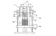
リフォーミングタブ5は、上部が開口している円筒形状のチャンバー11と、チャンバー11内で立設しているマンドレル12と、マンドレルの上端で同軸に連結されたノーズコーン13と、チャンバー11に支持されてノーズコーン13に向けて前進・後退する上アイリス14及び下アイリス15と、チャンバー11に支持されながら上下方向に移動するコイルプレート16と、を備えている。
図2は、本実施形態のリフォーミングタブ5と、上位コンピュータ6に接続してリフォーミングタブ5の駆動制御を行うリフォーミングタブ制御部10と、を示すものである。
リフォーミングタブ5は、上部が開口している円筒形状のチャンバー11と、チャンバー11内で立設しているマンドレル12と、マンドレルの上端で同軸に連結されたノーズコーン13と、チャンバー11に支持されてノーズコーン13に向けて前進・後退する上アイリス14及び下アイリス15と、チャンバー11に支持されながら上下方向に移動するコイルプレート16と、を備えている。
上アイリス14は、チャンバー11の周方向に所定間隔をあけて配置され、ノーズコーン13の下外周に向けて進退自在に配置された複数の上アイリスアーム17a,17b…と、各上アイリスアーム17a,17b…を前進・後退させる複数の上アイリス駆動部18a,18b…と、を備えている。そして、ノーズコーン13の下外周には、複数の上アイリスアーム17a,17b…がノーズコーン13に向けて前進したときに、それらの先端が入り込む上ノーズコーン穴19が形成されている。この上アイリス14は、閉動作を行うことで、次回の工程で製造され、これからコイルプレート16に集積される線材コイルCW2を一時的に貯える。
下アイリス15も、上アイリス14に対してチャンバー11の下に周方向に所定間隔をあけて配置されており、ノーズコーン13の下外周に向けて進退自在に配置された複数の下アイリスアーム20a,20b…と、各下アイリスアーム20a,20b…を前進・後退させる複数の下アイリス駆動部21a,21b…と、を備えている。そして、ノーズコーン13の下外周には、複数の下アイリスアーム20a,20b…がノーズコーン13に向けて前進したときに、それらの先端が入り込む下ノーズコーン穴22が形成されている。この下アイリス15は、閉動作を行うことで、この下アイリス15の下方位置にコイルプレート16が上昇してくるまで、先行する工程で集積している線材コイルCW1を一時的に貯える。
コイルプレート16は、上下方向に移動自在となるようにチャンバー11にガイドされ、コイルプレート駆動部16aの正逆方向の駆動により上昇、或いは下降する装置である。ここで、コイルプレート駆動部16aは、コイルプレート16を高速・低速仕様で上下方向に移動させることが可能な装置である。
また、図2に示すように、リフォーミングタブ制御部10は、上アイリス開閉制御部30と、下アイリス開閉制御部31と、コイルプレート上昇・下降制御部32と、を備えている。
また、図2に示すように、リフォーミングタブ制御部10は、上アイリス開閉制御部30と、下アイリス開閉制御部31と、コイルプレート上昇・下降制御部32と、を備えている。
上アイリス開閉制御部30は、複数の上アイリス駆動部18a,18b…に閉動作信号を出力することで、複数の上アイリス駆動部18a,18b…の駆動により複数の上アイリスアーム17a,17b…をノーズコーン13に向けて前進させ、それらの先端を上ノーズコーン穴19に入り込ませる。また、複数の上アイリス駆動部18a,18b…に開動作信号を出力することで、複数の上アイリス駆動部18a,18b…の逆方向の駆動により複数の上アイリスアーム17a,17b…をノーズコーン13から後退させていく。
下アイリス開閉制御部31は、複数の下アイリス駆動部21a,21b…に閉動作信号を出力することで、複数の下アイリス駆動部21a,21b…の駆動により複数の下アイリスアーム20a,20b…をノーズコーン13に向けて前進させ、それらの先端を下ノーズコーン穴22に入り込ませる。また、複数の下アイリス駆動部21a,21b…に開動作信号を出力することで、複数の下アイリス駆動部21a,21b…の逆方向の駆動により複数の下アイリスアーム20a,20b…をノーズコーン13から後退させていく。
また、コイルプレート上昇・下降制御部32は、コイルプレート駆動部16aに上昇移動の駆動信号を出力してコイルプレート16を上昇させことで、コイルプレート上昇制御処理を行う。また、コイルプレート駆動部16aに下方移動の駆動信号を出力してコイルプレート16を下降させことで、コイルプレート16を搬出位置まで下降させる。
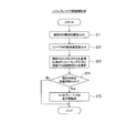
ここで、図3のフローチャートを参照して、コイルプレート上昇・下降制御部32が行うコイルプレート下降制御処理について説明する。
先ず、ステップST1において、上位コンピュータ6で記憶している線材圧延機2を通過した線材Wの尾端位置の情報を得る。
次に、ステップST2において、上位コンピュータ6で記憶しているコンベア4の搬送速度の情報を得る。
次に、ステップST3において、線材Wの尾端位置及びコンベア4の搬送速度の情報に基づいて、現在の工程でコイルプレート16に集積されている線材コイルCW1のコイル後端Cb側が、リフォーミングタブ5に到達する時刻(到達時刻)Hbを予測演算する。
先ず、ステップST1において、上位コンピュータ6で記憶している線材圧延機2を通過した線材Wの尾端位置の情報を得る。
次に、ステップST2において、上位コンピュータ6で記憶しているコンベア4の搬送速度の情報を得る。
次に、ステップST3において、線材Wの尾端位置及びコンベア4の搬送速度の情報に基づいて、現在の工程でコイルプレート16に集積されている線材コイルCW1のコイル後端Cb側が、リフォーミングタブ5に到達する時刻(到達時刻)Hbを予測演算する。
次に、ステップST4において、現在時刻が到達時刻Hbに達しているか否かを判定し、現在時刻が到達時刻Hbに達した場合にはステップST5に移行し、現在時刻がまだ到達時刻Hbに達していない場合には、コイルプレート下降制御処理を終了する。
ステップST5においては、コイルプレート駆動部16aに対して高速仕様で下方移動の駆動信号を出力することで、コイルプレート16を急下降させながら搬出位置まで下方移動させる。
この図3のフローチャートSで示したコイルプレート上昇・下降制御部32が行うコイルプレート下降制御処理は、現在時刻が到達時刻Hbに達するまで繰り返し実行される。
ステップST5においては、コイルプレート駆動部16aに対して高速仕様で下方移動の駆動信号を出力することで、コイルプレート16を急下降させながら搬出位置まで下方移動させる。
この図3のフローチャートSで示したコイルプレート上昇・下降制御部32が行うコイルプレート下降制御処理は、現在時刻が到達時刻Hbに達するまで繰り返し実行される。
なお、本願発明に記載されているコイル後端位置演算ステップが、図3のステップST1、ステップST2、ステップST3に対応し、本願発明に記載されている到達時刻演算ステップが図3のステップST3に対応し、本願発明に記載されているコイルプレート降下制御ステップが図3のステップST4、ステップST5に対応している。また、本願発明に記載されているコイル後端位置演算部が、図3のステップST1、ステップST2、ステップST3及びコイルプレート上昇・下降制御部31に対応し、本願発明に記載されている到達時刻演算部が、図3のステップST3及びコイルプレート上昇・下降制御部31に対応し、本願発明に記載されているコイルプレート降下制御部が、図3のステップST4、ステップST5及びコイルプレート上昇・下降制御部31に対応している。
さらに、本願発明に記載されているアイリスが、上アイリス15及び下アイリス16に対応し、本願発明に記載されているノーズコーン穴が、上ノーズコーン穴19及び下ノーズコーン穴22に対応している。
さらに、本願発明に記載されているアイリスが、上アイリス15及び下アイリス16に対応し、本願発明に記載されているノーズコーン穴が、上ノーズコーン穴19及び下ノーズコーン穴22に対応している。
〔リフォーミングタブの動作及び作用効果について〕
次に、本実施形態のリフォーミングタブ5の動作及び作用効果について、図4から図7を参照しながら説明する。
図4に示すように、搬出位置まで下降したコイルプレート16には線材コイルCWが集積されていたが、既に外部に搬出されたものとする。そして、上アイリス開閉制御部30の制御で、上アイリス14の複数の上アイリスアーム17a,17b…の先端をノーズコーン13の複数の上ノーズコーン穴19に入り込ませて上アイリス14の閉動作を行い、コンベア4から搬送されてきた線材コイルCW1は、ノーズコーン13を通過することで位置決めされながら一時的に上アイリス14に貯えられていく。
次に、本実施形態のリフォーミングタブ5の動作及び作用効果について、図4から図7を参照しながら説明する。
図4に示すように、搬出位置まで下降したコイルプレート16には線材コイルCWが集積されていたが、既に外部に搬出されたものとする。そして、上アイリス開閉制御部30の制御で、上アイリス14の複数の上アイリスアーム17a,17b…の先端をノーズコーン13の複数の上ノーズコーン穴19に入り込ませて上アイリス14の閉動作を行い、コンベア4から搬送されてきた線材コイルCW1は、ノーズコーン13を通過することで位置決めされながら一時的に上アイリス14に貯えられていく。
次に、図5に示すように、線材コイルCW1の集積位置にコイルプレート16が上昇してくるまで、上アイリス開閉制御部30の制御で上アイリス14の開動作を行い、下アイリス開閉制御部31の制御で下アイリス15の閉動作を行うことで、線材コイルCW1を上アイリス14から下アイリス15に移し替える。
次に、図6に示すように、コイルプレート16の集積位置への上昇が完了した後、下アイリス開閉制御部31の制御で下アイリス15の開動作を行うことで、下アイリス15に貯えていた線材コイルCW1をコイルプレート16に移し替え、コイルプレート16で線材コイルCW1が集積されていく。
次に、図6に示すように、コイルプレート16の集積位置への上昇が完了した後、下アイリス開閉制御部31の制御で下アイリス15の開動作を行うことで、下アイリス15に貯えていた線材コイルCW1をコイルプレート16に移し替え、コイルプレート16で線材コイルCW1が集積されていく。
ここで、コイルプレート上昇・下降制御部32は、上位コンピュータ6で記憶している線材Wの尾端位置と、コンベア4の搬送速度とに基づいて、線材コイルCW1のコイル後端Cb側がリフォーミングタブ5に到達する到達時刻Hbを演算する(図3のステップST3)。そして、現在時刻が到達時刻Hbに達した時点で、コイルプレート上昇・下降制御部32は、コイルプレート駆動部16aに対して高速仕様で下方移動の駆動信号を出力する(図3のステップST5)。
コイルプレート駆動部16aが高速仕様で下方移動を行うことで、図7に示すように、線材コイルCW1を集積したコイルプレート16が急降下動作を行う。このコイルプレート16の速度は50mm/sec~700mm/secの範囲であり、下降距離は3m程度である。
コイルプレート駆動部16aが高速仕様で下方移動を行うことで、図7に示すように、線材コイルCW1を集積したコイルプレート16が急降下動作を行う。このコイルプレート16の速度は50mm/sec~700mm/secの範囲であり、下降距離は3m程度である。
このとき、線材コイルCW1のコイル後端Cbは、ノーズコーン13の上方位置でリフォーミングタブ5に到達している。このコイル後端Cbは、コイルプレート16が急降下動作を行うことで、ノーズコーン13に形成されている上ノーズコーン穴19及び下ノーズコーン穴22に対して速度を高めながら通過していく。このため、コイル後端Cbが、上ノーズコーン穴19及び下ノーズコーン穴22に入り込み、引っ掛かるおそれがない。
そして、急降下動作を行ったコイルプレート16は搬出位置まで下降していき、コイルプレート16上の集積が完了した線材コイルCWは外部に搬出される。
そして、急降下動作を行ったコイルプレート16は搬出位置まで下降していき、コイルプレート16上の集積が完了した線材コイルCWは外部に搬出される。
したがって、本実施形態は、線材コイルCW1のコイル後端Cbがノーズコーン13の上方位置でリフォーミングタブ5に到達した時点で、コイルプレート16の急降下動作を行っていることから、このコイル後端Cbは、コイルプレート16が急降下動作を行うことで、ノーズコーン13に形成されている上ノーズコーン穴19及び下ノーズコーン穴22に対して速度を高めながら通過するので、上ノーズコーン穴19及び下ノーズコーン穴22に引っ掛かるおそれがない。したがって、リフォーミングタブ5のコイルプレート16に線材コイルCW1の集積が完了した際には作業員の監視が不要となり、リフォーミングタブ5における線材コイルCW1の集積作業の効率化を図ることができる。
なお、本実施形態では、線材コイルCW1のコイル後端Cbがノーズコーン13の上方に位置したときをリフォーミングタブ5に到達した時点としたが、線材コイルCW1のコイル後端側が残り5~6巻きのときをリフォーミングタブ5に到達した時点としてもよい。好ましくは、線材コイルCW1のコイル後端側が残り3~4巻きのときをリフォーミングタブ5に到達した時点としてもよい。
1 線材コイル製造ライン
2 線材圧延機
3 レイングヘッド
4 コンベア
5 リフォーミングタブ
6 上位コンピュータ
7 HMD
8 モータ
9 パルス発信器
10 フォーミングタブ制御部
11 チャンバー
12 マンドレル
13 ノーズコーン
14 上アイリス
15 下アイリス
16 コイルプレート
16a コイルプレート駆動部
17a,17b 上アイリスアーム
18a,18b 上アイリス駆動部
19 上ノーズコーン穴
20a,20b 下アイリスアーム
21a,21b 下アイリス駆動部
22 下ノーズコーン穴
30 上アイリス開閉制御部
31 下アイリス開閉制御部
32 コイルプレート上昇・下降制御部
W 線材
CW 線材コイル
CW1 現在の工程の線材コイル
CW2 次回の工程の線材コイル
Cb 線材コイルのコイル後端
Hb 到達時刻
2 線材圧延機
3 レイングヘッド
4 コンベア
5 リフォーミングタブ
6 上位コンピュータ
7 HMD
8 モータ
9 パルス発信器
10 フォーミングタブ制御部
11 チャンバー
12 マンドレル
13 ノーズコーン
14 上アイリス
15 下アイリス
16 コイルプレート
16a コイルプレート駆動部
17a,17b 上アイリスアーム
18a,18b 上アイリス駆動部
19 上ノーズコーン穴
20a,20b 下アイリスアーム
21a,21b 下アイリス駆動部
22 下ノーズコーン穴
30 上アイリス開閉制御部
31 下アイリス開閉制御部
32 コイルプレート上昇・下降制御部
W 線材
CW 線材コイル
CW1 現在の工程の線材コイル
CW2 次回の工程の線材コイル
Cb 線材コイルのコイル後端
Hb 到達時刻
Claims (6)
- 線材コイル製造ラインの上流設備から搬送されてきた線材コイルを集積するリフォーミングタブの制御方法であって、
前記リフォーミングタブは、搬送されてきた前記線材コイルを上部から通すことで前記線材コイルの位置決めをするノーズコーンと、前記ノーズコーンの下側外周に向けて前進・後退自在に配置されたアイリスと、前記アイリスの下方位置まで昇降自在に配置され、線材コイルを集積するコイルプレートと、を備え、前記アイリスは、前記ノーズコーンに設けたノーズコーン穴に入り込む閉動作を行うことで前記線材コイルを一時的に貯え、前記ノーズコーン穴から離れる開動作を行うことで前記線材コイルの貯えを前記コイルプレートに移し替えており、
前記コイルプレートに集積され続けており、前記上流設備で製造されている前記線材コイルのコイル後端位置を演算するコイル後端位置演算ステップと、
前記コイル後端位置が前記リフォーミングタブに到達する到達時刻を演算する到達時刻演算ステップと、
前記到達時刻に達した時点で前記コイルプレートを降下させるコイルプレート降下制御ステップと、
を備えていることを特徴とする線材コイル製造ラインにおけるリフォーミングタブの制御方法。 - 前記線材コイル製造ラインの上流設備は、線材を圧延する線材圧延機と、前記線材圧延機で圧延された前記線材をリング状に成形して線材コイルとするレイングヘッドと、前記レイングヘッドで成形された前記線材コイルを展開して搬送していき、終端の前記リフォーミングタブに前記線材コイルを供給するコンベアと、を備えており、
前記コイル後端位置演算ステップは、前記線材圧延機に配置した熱塊検出器の温度検出値の変化に基づいて、前記線材コイルのコイル後端位置を演算することを特徴とする請求項1記載の線材コイル製造ラインにおけるリフォーミングタブの制御方法。 - 前記コイル後端位置演算ステップは、前記線材圧延機に配置した熱塊検出器の温度検出値の変化とともに、前記コンベアの搬送速度に基づいて前記線材コイルのコイル後端位置を演算することを特徴とする請求項2記載の線材コイル製造ラインにおけるリフォーミングタブの制御方法。
- 線材コイル製造ラインの上流設備から搬送されてきた線材コイルを集積するリフォーミングタブの制御装置であって、
前記リフォーミングタブは、搬送されてきた前記線材コイルを上部から通すことで前記線材コイルの位置決めをするノーズコーンと、前記ノーズコーンの下側外周に向けて前進・後退自在に配置されたアイリスと、前記アイリスの下方位置まで昇降自在に配置され、線材コイルを集積するコイルプレートと、を備え、前記アイリスは、前記ノーズコーンに設けたノーズコーン穴に入り込む閉動作を行うことで前記線材コイルを一時的に貯え、前記ノーズコーン穴から離れる開動作を行うことで前記線材コイルの貯えを前記コイルプレートに移し替えており、
前記コイルプレートに集積され続けており、前記上流設備で製造されている前記線材コイルのコイル後端位置を演算するコイル後端位置演算部と、
前記コイル後端位置が前記リフォーミングタブに到達する到達時刻を演算する到達時刻演算部と、
前記到達時刻に達した時点で前記コイルプレートを降下させるコイルプレート降下制御部と、
を備えていることを特徴とする線材コイル製造ラインにおけるリフォーミングタブの制御装置。 - 前記線材コイル製造ラインの上流設備は、線材を圧延する線材圧延機と、前記線材圧延機で圧延された前記線材をリング状に成形して線材コイルとするレイングヘッドと、前記レイングヘッドで成形された前記線材コイルを展開して搬送していき、終端の前記リフォーミングタブに前記線材コイルを供給するコンベアと、を備えており、
前記コイル後端位置演算部は、前記線材圧延機に配置した熱塊検出器の温度検出値の変化に基づいて、前記線材コイルのコイル後端位置を演算することを特徴とする請求項4記載の線材コイル製造ラインにおけるリフォーミングタブの制御装置。 - 前記コイル後端位置演算部は、前記線材圧延機に配置した熱塊検出器の温度検出値の変化とともに、前記コンベアの搬送速度に基づいて前記線材コイルのコイル後端位置を演算することを特徴とする請求項5記載の線材コイル製造ラインにおけるリフォーミングタブの制御装置。
Priority Applications (1)
| Application Number | Priority Date | Filing Date | Title |
|---|---|---|---|
| CN202080008635.XA CN113286671B (zh) | 2019-01-10 | 2020-01-10 | 线材线圈生产线中重整槽的控制方法和装置 |
Applications Claiming Priority (2)
| Application Number | Priority Date | Filing Date | Title |
|---|---|---|---|
| JP2019-002768 | 2019-01-10 | ||
| JP2019002768A JP6984618B2 (ja) | 2019-01-10 | 2019-01-10 | 線材コイル製造ラインにおけるリフォーミングタブの制御方法及び装置 |
Publications (1)
| Publication Number | Publication Date |
|---|---|
| WO2020145390A1 true WO2020145390A1 (ja) | 2020-07-16 |
Family
ID=71520266
Family Applications (1)
| Application Number | Title | Priority Date | Filing Date |
|---|---|---|---|
| PCT/JP2020/000691 Ceased WO2020145390A1 (ja) | 2019-01-10 | 2020-01-10 | 線材コイル製造ラインにおけるリフォーミングタブの制御方法及び装置 |
Country Status (3)
| Country | Link |
|---|---|
| JP (1) | JP6984618B2 (ja) |
| CN (1) | CN113286671B (ja) |
| WO (1) | WO2020145390A1 (ja) |
Cited By (1)
| Publication number | Priority date | Publication date | Assignee | Title |
|---|---|---|---|---|
| TWI853674B (zh) * | 2023-08-17 | 2024-08-21 | 聚亨企業股份有限公司 | 線材除鏽設備之出料裝置 |
Citations (4)
| Publication number | Priority date | Publication date | Assignee | Title |
|---|---|---|---|---|
| JPS5358933U (ja) * | 1976-10-21 | 1978-05-19 | ||
| JPH0323015A (ja) * | 1989-06-20 | 1991-01-31 | Sumitomo Metal Ind Ltd | 線材の集束装置 |
| JP2011173162A (ja) * | 2010-02-25 | 2011-09-08 | Jfe Steel Corp | 熱間長尺材の長さ測定方法および装置 |
| JP2015515928A (ja) * | 2012-05-04 | 2015-06-04 | シーメンス・ファオアーイー・メタルズ・テクノロジーズ・ゲーエムベーハー | コイル形成装置 |
Family Cites Families (5)
| Publication number | Priority date | Publication date | Assignee | Title |
|---|---|---|---|---|
| GB1339334A (en) * | 1971-11-19 | 1973-12-05 | Essex International Inc | Method and apparatus for winding dynamoelectric machine field coils |
| JP2007021515A (ja) * | 2005-07-13 | 2007-02-01 | Sumitomo Metal Ind Ltd | 線材コイル製造装置及びそれを用いた線材コイルの製造方法 |
| CN107983783A (zh) * | 2016-10-27 | 2018-05-04 | 张宇 | 高速线材轧线的自动化集卷装置及方法 |
| CN106623490A (zh) * | 2016-12-23 | 2017-05-10 | 四川省达州钢铁集团有限责任公司 | 一种高线线圈盘卷系统 |
| CN207358560U (zh) * | 2017-09-01 | 2018-05-15 | 广州市金钟汽车零件股份有限公司 | 一种卧式大盘卡簧一体机 |
-
2019
- 2019-01-10 JP JP2019002768A patent/JP6984618B2/ja active Active
-
2020
- 2020-01-10 WO PCT/JP2020/000691 patent/WO2020145390A1/ja not_active Ceased
- 2020-01-10 CN CN202080008635.XA patent/CN113286671B/zh active Active
Patent Citations (4)
| Publication number | Priority date | Publication date | Assignee | Title |
|---|---|---|---|---|
| JPS5358933U (ja) * | 1976-10-21 | 1978-05-19 | ||
| JPH0323015A (ja) * | 1989-06-20 | 1991-01-31 | Sumitomo Metal Ind Ltd | 線材の集束装置 |
| JP2011173162A (ja) * | 2010-02-25 | 2011-09-08 | Jfe Steel Corp | 熱間長尺材の長さ測定方法および装置 |
| JP2015515928A (ja) * | 2012-05-04 | 2015-06-04 | シーメンス・ファオアーイー・メタルズ・テクノロジーズ・ゲーエムベーハー | コイル形成装置 |
Cited By (1)
| Publication number | Priority date | Publication date | Assignee | Title |
|---|---|---|---|---|
| TWI853674B (zh) * | 2023-08-17 | 2024-08-21 | 聚亨企業股份有限公司 | 線材除鏽設備之出料裝置 |
Also Published As
| Publication number | Publication date |
|---|---|
| CN113286671A (zh) | 2021-08-20 |
| JP2020110816A (ja) | 2020-07-27 |
| JP6984618B2 (ja) | 2021-12-22 |
| CN113286671B (zh) | 2023-12-08 |
Similar Documents
| Publication | Publication Date | Title |
|---|---|---|
| CN104249091B (zh) | 一种取向硅钢连退机组卷取张力的控制方法 | |
| US20250269413A1 (en) | Automated rod coil cutting station | |
| JP6377265B2 (ja) | 金属ストリップを酸洗および圧延するための複合型酸洗−圧延プラント | |
| JP2014087830A (ja) | 扁平チューブ用フィンの製造装置 | |
| JP6181157B2 (ja) | コイル形成装置 | |
| JP2020110816A (ja) | 線材コイル製造ラインにおけるリフォーミングタブの制御方法及び装置 | |
| CN117943645A (zh) | 一种线切割设备的自动接丝穿丝拆丝方法 | |
| CN111438536A (zh) | 一种钢材加工设备及加工方法 | |
| US2135913A (en) | Reeling device | |
| CN112872099B (zh) | 一种钢卷卸卷的方法及装置 | |
| CN213678585U (zh) | 一种线材盘卷输送及切尾移卷装置 | |
| EP2812133B1 (en) | Entry section of a pickling line, of a continuous tandem cold mill (tcm) or of a pickling line coupled to tandem cold mill (pl/tcm) installation | |
| CN111570527A (zh) | 全连续热轧薄带线卷取机切换过程中导板的控制方法 | |
| EP3208005B1 (en) | Combined welding and rolling plant for metallic strips | |
| CN116435088A (zh) | 一种具有激光喷码、视觉纠偏的绕线设备及其工作流程 | |
| JP2000271643A (ja) | 条材巻取設備 | |
| JPH0436766B2 (ja) | ||
| TWI714002B (zh) | 用於220℃以上漆包線的電感加工設備 | |
| EP1126936B1 (en) | Device to remove coils of rolled stock from a corresponding coiling machine | |
| JP2022149465A (ja) | 線材集積コイルの分割方法及び線材コイルの製造方法 | |
| JP2858365B2 (ja) | 帯状材料のアキュームレータ | |
| JP2007152354A (ja) | 線材圧延設備の線材搬送コンベヤおよびその線材搬送コンベヤにおける線材切断方法 | |
| JP2017148822A (ja) | 熱延鋼板の巻取方法および巻取装置 | |
| JP2014200814A (ja) | バーインコイルの尾端処理装置 | |
| CN103521552A (zh) | 镁合金板轧制开卷机组 |
Legal Events
| Date | Code | Title | Description |
|---|---|---|---|
| 121 | Ep: the epo has been informed by wipo that ep was designated in this application |
Ref document number: 20738805 Country of ref document: EP Kind code of ref document: A1 |
|
| NENP | Non-entry into the national phase |
Ref country code: DE |
|
| 122 | Ep: pct application non-entry in european phase |
Ref document number: 20738805 Country of ref document: EP Kind code of ref document: A1 |