WO2020145333A1 - 印刷装置及び印刷方法 - Google Patents
印刷装置及び印刷方法 Download PDFInfo
- Publication number
- WO2020145333A1 WO2020145333A1 PCT/JP2020/000406 JP2020000406W WO2020145333A1 WO 2020145333 A1 WO2020145333 A1 WO 2020145333A1 JP 2020000406 W JP2020000406 W JP 2020000406W WO 2020145333 A1 WO2020145333 A1 WO 2020145333A1
- Authority
- WO
- WIPO (PCT)
- Prior art keywords
- pattern
- main scanning
- printing
- ejection position
- ink
- Prior art date
- Legal status (The legal status is an assumption and is not a legal conclusion. Google has not performed a legal analysis and makes no representation as to the accuracy of the status listed.)
- Ceased
Links
Images



Classifications
-
- B—PERFORMING OPERATIONS; TRANSPORTING
- B41—PRINTING; LINING MACHINES; TYPEWRITERS; STAMPS
- B41J—TYPEWRITERS; SELECTIVE PRINTING MECHANISMS, i.e. MECHANISMS PRINTING OTHERWISE THAN FROM A FORME; CORRECTION OF TYPOGRAPHICAL ERRORS
- B41J2/00—Typewriters or selective printing mechanisms characterised by the printing or marking process for which they are designed
- B41J2/005—Typewriters or selective printing mechanisms characterised by the printing or marking process for which they are designed characterised by bringing liquid or particles selectively into contact with a printing material
- B41J2/01—Ink jet
- B41J2/135—Nozzles
- B41J2/165—Prevention or detection of nozzle clogging, e.g. cleaning, capping or moistening for nozzles
Definitions
- the present invention relates to a printing device and a printing method.
- inkjet printers which are printing devices that perform inkjet printing, have been widely used. Further, conventionally, a configuration is known in which flushing is performed with respect to a maintenance operation for an inkjet head used in an inkjet printer (for example, see Patent Document 1). Flushing is, for example, a method of performing maintenance of the inkjet head by ejecting ink from the nozzles of the inkjet head. By performing the flushing regularly, for example, it is possible to prevent the ink from drying or thickening in the vicinity of the nozzle.
- a maintenance station that is configured to perform maintenance on the inkjet head, move the inkjet head to the position of the maintenance station, and eject the ink to the inkjet head. Further, when printing with high quality, it is desirable to perform flushing regularly even during printing operation, for example. Then, in this case, for example, it is conceivable to move the maintenance station to a position in the middle of the movement path of the inkjet head in the main scanning operation (scan operation) performed by the inkjet head, and perform flushing during the main scanning operation.
- a configuration for example, a flushing box
- the flushing can be performed regularly during the printing operation.
- an object of the present invention is to provide a printing apparatus and a printing method that can solve the above problems.
- the inventor of the present application has earnestly conducted research on a method for flushing an inkjet head. Then, first, it was considered to perform flushing on a medium to be printed by a method of ejecting ink from an inkjet head. In this case, for example, it may be possible to cause the inkjet head to perform flushing by controlling the operation of the inkjet head so as to further print a predetermined pattern in addition to the print image that is the image to be printed. According to this structure, for example, the inkjet head can be made to perform flushing without using a maintenance station, a flushing box, or the like.
- various processing such as image processing according to the printing conditions is performed on the data (print image data) showing the print image as it is. More specifically, in this case, for example, RIP (Raster Image Processor) processing or the like may be performed according to the number of colors of ink used in the printing apparatus, the resolution of printing, and the like.
- RIP Raster Image Processor
- the part of the pattern added to perform the flushing is also the target of the process, which may cause an unintended change. Further, as a result, there is a possibility that flushing cannot be performed under desired conditions.
- the inventor of the present application has conducted further diligent research to print data generated by the RIP process or the like, rather than adding a predetermined pattern to the image before the RIP process or the like. It was considered to make a correction (change) to add a predetermined pattern in the device. With this configuration, for example, flushing under desired conditions can be performed more appropriately. Further, the method of adding a pattern in this manner can be similarly used in the case of adding a pattern for a purpose other than flushing, for example.
- the present invention is a printing apparatus that performs printing on a medium by an inkjet method, the inkjet head ejecting ink to the medium by the inkjet method, and ejecting ink by the inkjet head.
- a control unit that controls the operation of the inkjet head based on ejection position designation data indicating a print image that is an image to be printed by designating the ejection position.
- correction is performed to add the ejection position so that a preset pattern is further printed in addition to the print image, and ink is ejected to the inkjet head based on the corrected ejection position designation data.
- the inkjet head can be made to perform flushing or the like. Further, in this case, by correcting the data designating the ejection position, it is possible to more reliably and properly designate the position where the ink is ejected for flushing or the like.
- ejecting ink to the inkjet head is, for example, ejecting ink to each nozzle in the inkjet head.
- a pattern for causing the inkjet head to perform flushing it is possible to use a pattern for causing the inkjet head to perform flushing.
- the pattern for example, it is conceivable to use a pattern in which the inkjet head ejects ink to an ejection position that does not overlap the print image on the medium. With this configuration, for example, the inkjet head can be appropriately flushed.
- ejection position designation data for example, data generated by performing RIP processing on the data indicating the print image can be preferably used. With this configuration, for example, it is possible to appropriately prevent the condition for performing flushing from changing due to the RIP process.
- the printing apparatus performs printing on the medium by a multi-pass method in which the main scanning operation is performed a plurality of times for each position of the area where the print image is printed on the medium.
- the printing apparatus performs printing on the medium by a multi-pass method in which the number of passes is N (N is an integer of 2 or more).
- the main scanning operation is, for example, an operation of ejecting ink while moving relatively to the medium in a preset main scanning direction.
- the printing apparatus further includes, for example, a main-scanning drive unit that causes the inkjet head to perform the main-scanning operation, and a sub-scanning drive unit that causes the inkjet head to perform the sub-scanning operation.
- the sub-scanning operation is, for example, an operation of moving relative to the medium in the sub-scanning direction orthogonal to the main scanning direction.
- the portion corresponding to the pattern is also printed by the multi-pass method. It will be.
- the amount of ink ejected to the position corresponding to the pattern in each main scanning operation decreases according to the number of passes. Therefore, when the pattern is added in this way, it may be difficult to perform flushing or the like under desired conditions.
- the ejection position designating data may be, for example, a print image. It is conceivable to use data including main scanning data corresponding to each main scanning operation performed for printing. Then, in this case, the control unit performs correction for adding the ejection position corresponding to the pattern to the main scanning data corresponding to at least one of the main scanning operations. With this configuration, for example, flushing under desired conditions can be performed more appropriately.
- flushing may be performed in all main scanning operations.
- the control unit performs, for example, the correction for adding the ejection position corresponding to the pattern to the main scanning data corresponding to all the main scanning operations.
- appropriate printing may be performed without necessarily performing flushing in every main scanning operation.
- the control unit may perform correction for adding the ejection position corresponding to the pattern to the main scanning data corresponding to the main scanning operation only for some times.
- the discharge corresponding to the pattern is performed.
- the main scanning data before the correction for adding the position can be considered as data in which the printing density is lower than the total ejection density Md according to the number of passes.
- the ejection position is specified so that the printing density is equal to or lower than Md/N, which is the number obtained by dividing the total ejection density Md by the number N of passes. It can be considered as data.
- the control unit determines, for example, for the main scanning data corresponding to at least one of the main scanning operations, the density of printing by the ink ejected to the position corresponding to the pattern in one main scanning operation.
- the correction for adding the ejection position corresponding to the pattern is performed so as to be larger than Md/N. According to this structure, for example, even when the print image is printed by the multi-pass method, the ink can be ejected from the inkjet head at a higher printing density to the portion corresponding to the pattern.
- the printing apparatus further includes, for example, an image information storage unit that stores a raster image indicated by the main scanning data corresponding to at least the next main scanning operation.
- the image information storage unit for example, a known image storage memory (image information memory) can be preferably used.
- the control unit performs correction, for example, on the raster image stored in the image information storage unit to change the value of the pixel at the position corresponding to the pattern. According to this structure, for example, the correction for adding the ejection position corresponding to the pattern can be appropriately performed on the main scanning data.
- the area for adding the ejection position is secured, and then the ejection position corresponding to the pattern is added. It is also possible to do it. Further, as a method of securing such an area, for example, changing the position where the print image is printed, processing of deleting a part of the print image, and the like are considered. More specifically, in the correction for adding the ejection position corresponding to the pattern to the main scanning data, the control unit changes the position at which the print image is printed on the medium and then prints on the medium, for example. The ejection position corresponding to the pattern is added so as not to overlap the image.
- the control unit deletes a part of the print image and then, for example, within a range corresponding to the part deleted from the print image.
- an ejection position corresponding to the pattern may be added. With such a configuration, for example, the ejection position designation data can be corrected more appropriately.
- the control unit receives, for example, ejection position designation data from a device outside the printing device.
- the device outside the printing device is, for example, a computer or the like that controls the operation of the printing device.
- the control unit for example, in the printing apparatus, performs correction for adding the ejection position to the ejection position designation data so that the pattern is further printed.
- the process of adding a pattern can be appropriately performed after the data indicating the print image is provided to the printing apparatus.
- the printing apparatus further includes, for example, a firmware storage unit that stores firmware that is a program that controls the operation of the printing apparatus.
- the control unit corrects the ejection position designation data according to the firmware stored in the firmware storage unit, for example.
- the ejection position designation data can be appropriately corrected in the printing apparatus.
- the control unit may decide, for example, what kind of pattern to add in accordance with a user's instruction.
- the control unit receives from the user, for example, the width of the pattern and the designation of the density of the print that ejects ink when the pattern is formed. Then, based on the user's designation, the ejection position designation data is corrected to add the ejection position so that the pattern is further printed.
- the pattern to be added can be variously changed according to the user's instruction. Further, as a result, for example, the flushing condition and the like can be variously changed as necessary.
- FIG. 1A shows an example of the configuration of the printing system 10.
- FIG. 1B shows an example of the configuration of the printing device 12.
- FIG. 1C shows an example of the configuration of the head unit 102 in the printing device 12.
- FIG. 7 is a diagram for explaining in more detail the correction for adding a predetermined pattern performed by the control unit 120.
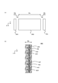
- FIG. 2A shows an example of processing for adding a pattern.
- FIG. 2B shows an example of the configuration of the pattern unit 304. It is a figure which explains the characteristic of the area
- FIG. 3A shows an example of a detailed configuration of one area 402 in the pattern unit 304.
- FIG. 3A shows an example of a detailed configuration of one area 402 in the pattern unit 304.
- FIG. 3B is an enlarged view showing the positional relationship of a plurality of dots 502 formed close to each other in one region 402. It is a figure which explains in more detail about the correction etc. which add a pattern.
- FIG. 4A is a diagram for explaining the data processing and the like performed in the printing system 10 in more detail.
- FIG. 4B shows a modification of the operation of the printing device 12.
- FIG. 9 is a diagram illustrating a method of ejecting ink when the pattern printing density is reduced and the pattern width is increased.
- FIG. 1 is a diagram illustrating a printing system 10 according to an embodiment of the present invention.
- FIG. 1A shows an example of the configuration of the printing system 10. It should be noted that the printing system 10 of this example may have the same or similar characteristics as a known printing system, except for the points described below.
- the printing system 10 is a system that prints on a medium to be printed by an inkjet method, and includes a printing device 12 and a host PC.
- the printing device 12 is an inkjet printer that prints on a medium by an inkjet method, and executes a printing operation based on print input data received from the host PC 14.
- the print input data is, for example, input data indicating a print image that is an image to be printed.
- the print input data is an example of ejection position designation data.
- the ejection position designation data is, for example, data indicating a print image by designating the ejection position at which ink is ejected by the inkjet head of the printing device 12.
- the host PC 14 is a computer that controls the operation of the printing device 12.
- the host PC 14 generates print input data outside the printing device 12 and supplies the generated print input data to the printing device 12, thereby operating the printing device 12.
- the host PC 14 generates print input data by performing RIP (Raster Image Processor) processing.
- the RIP process is, for example, a process of generating an image in a raster format that matches the number of colors of ink used in the printing device 12, the resolution of printing, and the like.
- RIP Raster Image Processor
- the RIP process is, for example, a process of generating an image in a raster format that matches the number of colors of ink used in the printing device 12, the resolution of printing, and the like.
- print input data supplied from the host PC 14 to the printing device 12 data generated by performing a known RIP process or the like can be preferably used.
- the process of generating print input data in the host PC 14 can be the same as or similar to the known process, for example. The process of
- FIG. 1B shows an example of the configuration of the printing device 12.
- FIG. 1C shows an example of the configuration of the head unit 102 in the printing device 12.
- the printing device 12 includes a head unit 102, a platen 104, a main scanning drive unit 106, a sub-scanning drive unit 108, an image information memory 110, a firmware storage unit 112, and a control unit 120.
- the printing device 12 may have the same or similar characteristics as those of a known inkjet printer except for the points described above and below.
- the printing device 12 may further have various configurations necessary for printing operation and the like.
- the printing device 12 may further include a fixing unit or the like for fixing the ink on the medium 50, depending on the type of ink used.
- the head portion 102 is a portion that ejects ink onto the medium 50.
- the head unit 102 has a plurality of heads, as shown in FIG. 1C as an inkjet head 202y, an inkjet head 202m, an inkjet head 202c, and an inkjet head 202k (hereinafter referred to as inkjet heads 202y to 202k). It has an inkjet head.
- each of the inkjet heads 202y to 202k is an inkjet head that ejects inks of different colors onto the medium 50 by an inkjet method, and has a preset sub-scanning direction (X direction in the drawing) in the printer 12.
- Ink is ejected toward the medium 50 from each of the nozzles having a plurality of nozzles that are arranged at different positions.
- the inkjet heads 202y to 202k are arranged side by side in the main scanning direction (Y direction in the drawing) orthogonal to the sub scanning direction with their positions aligned in the sub scanning direction.
- the ink of each color ejected from the inkjet heads 202y to 202k is the ink of each basic color (process color) used for color printing (for example, full-color printing). More specifically, the inkjet head 202y ejects yellow (Y) ink. The inkjet head 202m ejects magenta (M) color ink. The inkjet head 202c ejects cyan (C) ink. The inkjet head 202k ejects black (K) ink.
- the platen 104 is a trapezoidal member that holds the medium 50 at a position facing the head unit 102.
- the main scanning driving unit 106 is a driving unit that causes the inkjet heads 202y to 202k in the head unit 102 to perform a main scanning operation.
- the main scanning operation is an operation of ejecting ink while moving relatively to the medium 50 in the main scanning direction.
- the main scanning drive unit 106 moves the inkjet heads 202y to 202k in the main scanning direction with respect to the medium 50 whose position in the main scanning direction is fixed, thereby causing the inkjet heads 202y to 202k to perform main scanning.
- the scanning operation is performed.
- the sub-scanning drive unit 108 is a drive unit that causes the inkjet heads 202y to 202k to perform a sub-scanning operation.
- the sub-scanning operation is an operation of moving relative to the medium 50 in the sub-scanning direction.
- the sub-scanning drive unit 108 moves the medium 50 side by, for example, using a roller (not shown) or the like to convey the medium 50 in the conveyance direction parallel to the sub-scanning direction, The inkjet heads 202y to 202k are caused to perform a sub-scanning operation.
- the image information memory 110 is a memory for image storage that functions as an example of an image information storage unit, and stores a raster image indicating the position where ink is ejected in the main scanning operation.
- the firmware storage unit 112 is a storage unit that stores firmware that is a program that controls the operation of the printing apparatus 12.
- the control unit 120 is configured to include the CPU of the printing device 12, for example, and controls the operation of each unit of the printing device 12 by operating according to the firmware stored in the firmware storage unit 112. More specifically, the control unit 120 controls the operation of the inkjet heads 202y to 202k based on the print input data received from the host PC 14. Further, in this case, the control unit 120, for example, based on the print input data, at least before each main scanning operation is performed, a raster image indicating a position where ink is ejected in the main scanning operation at that time is stored in the image information memory. It is stored in 110.
- the control unit 120 controls the ejection position for ejecting ink to the inkjet heads 202y to 202k based on the raster image stored in the image information memory 110. According to this example, for example, it is possible to appropriately print the print image indicated by the print input data.
- the printing device 12 performs printing on the medium 50 by the multi-pass method.
- the multi-pass method is a method in which the main scanning operation is performed a plurality of times for each position in the area where the print image is printed on the medium 50.
- Performing the main scanning operation a plurality of times for each position means performing the main scanning operation such that the number of times the inkjet heads 202y to 202k pass the position facing each position a plurality of times.
- the sub-scanning drive unit 108 performs the sub-scanning operation with the feed amount determined according to the number of passes, which is the number of main scanning operations performed for each position. 202y-k.
- the feed amount in the sub-scanning operation may be set to a distance corresponding to a value (L/N) obtained by dividing the nozzle length by N, for example.
- the host PC 14 generates print input data indicating the ejection position at which the ink is ejected in each main scanning operation in accordance with the operation of the printing apparatus 12 in the multi-pass method. More specifically, for example, when the data designating the ejection positions at which the inkjet heads 202y to 202k eject ink in one main scanning operation is defined as the main scanning data, the host PC 14 prints a print image.
- the print input data including the main scanning data corresponding to each main scanning operation to be performed is generated.
- the main scanning data can be considered as, for example, data indicating an ejection position at which ink is ejected by one ink jet head in one main scanning operation.
- the print input data including such main scanning data can be considered as, for example, data indicating an ejection position at which ink is ejected in each main scanning operation for each color of ink used for printing.
- the main scanning data can be considered as a raster image showing an image corresponding to the ejection position by designating the ejection position, for example.
- the image information memory 110 stores, for example, a raster image corresponding to each main scanning operation. In this case, the image information memory 110 stores at least the raster image indicated by the main scanning data corresponding to the next main scanning operation.
- control unit 120 performs correction for adding a predetermined pattern to the raster image stored in the image information memory 110.
- the correction for adding the predetermined pattern is, for example, a correction performed so that the ink is further ejected to the ejection position corresponding to the predetermined pattern in each main scanning operation.
- a pattern for causing the inkjet heads 202y to 202k to perform flushing is used as a pattern to be added in this way.
- the flushing will be described in more detail later.
- the control unit 120 performs, for example, correction for adding the ejection position corresponding to the pattern to the main scanning data corresponding to at least one of the main scanning operations.
- the control unit 120 performs correction for adding the ejection position to the print input data so that the preset pattern is further printed in addition to the print image.
- the inkjet heads 202y to 202k are caused to eject ink based on the corrected print input data.
- ejecting ink to the inkjet heads 202y to 202k means, for example, ejecting ink to each nozzle in each of the inkjet heads 202y to 202k.
- the corrected print input data is, for example, the corrected main scan in which the main scan data included in the print input data at the time of input to the printing device 12 is corrected as described above or below. It is the data that has been replaced with the work data. Further, “based on the corrected print input data” may be based on, for example, the corrected main scanning data. Further, the correction for adding the predetermined pattern will be described in more detail below.
- FIG. 2 is a diagram for explaining in more detail the correction for adding a predetermined pattern performed by the control unit 120 (see FIG. 1).
- the printing device 12 receives the print input data from the host PC 14 (see FIG. 1) which is a device outside the printing device 12. Then, the correction operation is executed by the control unit 120 in accordance with the firmware stored in the firmware storage unit 112 (see FIG. 1) to indicate the ink ejection position for printing the print image in the printing device 12.
- the print input data is corrected by adding an ejection position so that a predetermined pattern is further printed.
- the process of adding a pattern or the like can be appropriately performed.
- FIG. 2A is a diagram showing an example of a process of adding a pattern, and shows an example of an image drawn on the medium 50 by one main scanning operation by the inkjet heads 202y to 202k (see FIG. 1).
- 2A for example, based on the raster image stored in the image information memory 110, the range of the image drawn by the ink jet heads 202y to 202k ejecting ink in one main scanning operation. Can be considered to indicate.
- the raster image stored in the image information memory 110 is a raster image after correction for adding a pattern.
- the printing apparatus 12 receives the print input data including the main scanning data corresponding to each main scanning operation for printing the print image from the host PC 14. ..
- the main scanning data corresponding to each main scanning operation can be considered to indicate a raster image corresponding to a part of the print image.
- such main scanning data can be considered as, for example, raster image data in which ejection positions for ejecting ink in the corresponding main scanning operation are associated with pixels.
- this raster image can be considered as, for example, an image showing the ejection position at which ink is ejected in the main scanning operation at that time.
- the control unit 120 for example, based on the print input data, before the main scanning operation of each time is performed, the control unit 120 indicates the raster where the ink is ejected in the main scanning operation of the time.
- the image is stored in the image information memory 110.
- the control unit 120 further adds a predetermined pattern by correcting the raster image stored in the image information memory 110.
- adding a predetermined pattern by correcting the raster image means correcting the raster image so that the ink is ejected to the ejection position corresponding to the predetermined pattern in the main scanning operation at that time.
- control unit 120 performs correction for changing the value of the pixel at the position corresponding to the pattern, for example, for the raster image stored in the image information memory 110.
- the pixel value may be changed to a value indicating that ink is ejected.
- the correction for adding the ejection position corresponding to the pattern can be appropriately performed on the main scanning data.
- the image information memory 110 stores, for example, a raster image including areas corresponding to the print image corresponding portion 302 and the pattern portion 304 shown in the drawing. Further, more specifically, in the present example, the image information memory 110 stores, for example, a raster image that is color-separated for each color of ink. Then, in this case, the image information memory 110 stores the image corresponding to the ejection position of the ink for one color in the area corresponding to the print image corresponding portion 302 and the pattern portion 304 in the raster image corresponding to each color.
- the print image corresponding portion 302 is a portion corresponding to the print image, and shows a portion of the print image that ejects ink in the main scanning operation at that time.
- the print image corresponding portion 302 can be considered as, for example, a portion corresponding to the raster image before correction.
- the width of the print image corresponding portion 302 in the main scanning direction (Y direction) is Wa.
- the width Wa is set according to the width of the print image, for example.
- the width in the sub-scanning direction (X direction) is the width corresponding to the nozzle length of the inkjet head.
- the pattern portion 304 is a portion corresponding to the pattern added by the correction.
- the pattern portions 304 are added to both sides of the print image corresponding portion 302 in the main scanning direction with a blank portion sandwiched between the pattern portion 304 and the print image corresponding portion 302.
- the width of the pattern portion 304 in the main scanning direction is Wb.
- the width in the sub-scanning direction corresponds to the nozzle length of the inkjet head.
- the width (width in the main scanning direction) of the blank portion between the print image corresponding portion 302 and the pattern portion 304 is Wc.
- the width Wb of the pattern portion 304 and the width Wc of the blank portion may be set according to, for example, a user's instruction to specify a pattern to be added.
- FIG. 2B shows an example of the configuration of the pattern unit 304.
- the printing device 12 performs correction for adding a pattern to the print input data received from the host PC 14. Further, as a result, the pattern is printed on the medium 50 in addition to the print image.
- flushing is a method of performing maintenance of the inkjet head by periodically ejecting ink from the nozzles of the inkjet head.
- the pattern for performing flushing can also be considered as, for example, a discarding pattern or the like for ejecting ink to the inkjet head for purposes other than printing of a print image.
- a pattern for performing flushing for example, a ladder pattern drawn by all the nozzles of each of the inkjet heads 202y to 202k can be preferably used.
- the control unit 120 of the printing apparatus 12 adds a pattern unit 304 at a position that does not overlap the print image corresponding unit 302, as shown in FIG. 2A, for example. Then, flushing is performed by using the operation of ejecting ink to draw the pattern portion 304. Therefore, the pattern added in this example can be considered as, for example, a pattern in which ink is ejected to the inkjet heads 202y to 202k to an ejection position that does not overlap the print image on the medium 50.
- the pattern formed in the pattern portion 304 for example, as shown in FIG.
- a color bar-shaped pattern including a plurality of regions 402 of mutually different colors is formed.
- the plurality of regions 402 are regions that form a part of the pattern unit 304 in the main scanning direction. Therefore, the width of each area 402 in the sub-scanning direction corresponds to the nozzle length of the inkjet head. According to this structure, in each main scanning operation, for example, ink can be ejected to the region 402 from all the nozzles of the inkjet head.
- the control unit 120 causes the ink jet heads 202y to 202k to eject ink from all nozzles a plurality of times, for example.
- flushing can be appropriately performed on each of the inkjet heads 202y to 202k.
- ink is ejected from all the nozzles of one inkjet head a plurality of times to at least one of the regions 402.
- the inkjet heads 202y to 202k can be appropriately flushed by adding a predetermined pattern to the print image, for example. Further, in this case, by correcting the data designating the ejection position, it is possible to more reliably and appropriately designate the position where the ink is ejected for flushing or the like. Further, in this case, by ejecting the ink onto the medium 50, the inkjet heads 202y to 202k can be appropriately flushed without using, for example, a maintenance station or a flushing box.
- FIG. 3 is a diagram for explaining the features of the region 402 in more detail.
- FIG. 3A is a diagram showing an example of a detailed configuration of one area 402 in the pattern unit 304. For one area 402 filled with the same color (one color), ink of the area 402 is formed. An example of how the dots 502 are arranged is shown.
- FIG. 3B is an enlarged view showing the positional relationship of a plurality of dots 502 formed close to each other in one region 402.
- the ink dots 502 are formed side by side in the main scanning direction and the sub scanning direction.
- the width of one region 402 in the main scanning direction is Wd.
- the plurality of dots 502 in the area 402 are arranged with a constant interval in the main scanning direction and the sub scanning direction. More specifically, the plurality of dots 502 are arranged at regular intervals, with an interval in the main scanning direction being dy and an interval in the sub scanning direction being dx, as shown in FIG. 3B, for example.
- the interval dy in the main scanning direction is determined according to the interval (time interval) at which ink is ejected from one nozzle during the main scanning operation and the moving speed of the inkjet head during the main scanning operation. Further, the spacing dx in the sub-scanning direction is determined according to the spacing (distance spacing) between the nozzles in one inkjet head in the sub-scanning direction.
- flushing is performed by ejecting ink to the inkjet heads 202y to 202k on the medium 50, generally, the more the ink is ejected, the greater the effect of flushing.
- the density of the ink dots 502 forming the respective regions 402 in the pattern portion 304 it is possible to adjust the ink ejection amount during flushing.
- the width Wd of one region 402 in the main scanning direction or the interval dy of the dots 502 in the region 402 in the main scanning direction during flushing. It is possible to change the ink ejection amount.
- the printing apparatus 12 adjusts the ejection amount of ink during flushing by setting these parameters according to the user's instruction. More specifically, in this case, the control unit 120 in the printing device 12 receives, from the user, the designation of the width of the pattern, the density of printing for ejecting ink when forming the pattern, and the like.
- the pattern width is the width Wb of the pattern unit 304 in the sub-scanning direction.
- control of the ink ejection amount during flushing control of flushing
- the control unit 120 may receive, as a parameter indicating the width of the pattern, a designation of the width Wd of one region 402 from the user, for example.
- the user receives a designation of a level (hereinafter referred to as a refresh level) that is associated in advance with the ink ejection amount during flushing.
- a refresh level a designation of a level
- the user can receive the designation of the print density by causing the user to select any one of a plurality of refresh levels associated with different ejection amounts.
- the flushing amount and continuity can be controlled.
- the control unit 120 for example, according to the user's instruction, the ejection position so that the pattern according to the specified condition is further printed on the main scanning data forming the print input data.
- Make a correction to add for example, the ejection position to be added is determined by adjusting the width of each region 402, the distance dy between the dots 502 in the main scanning direction, and the like according to the width of the designated pattern and the refresh level. It is possible. With this configuration, for example, what kind of pattern to add can be appropriately determined according to the user's instruction. Further, by changing the pattern to be added variously, for example, the flushing condition and the like can be variously changed as necessary. Therefore, according to this example, for example, flushing under desired conditions can be performed more appropriately.
- FIG. 4 is a diagram for explaining the correction and the like for adding a pattern in more detail.
- FIG. 4A is a diagram for explaining the data processing and the like performed in the printing system 10 in more detail.
- the host PC 14 performs the RIP process to generate the print input data. More specifically, in this example, the host PC 14 generates print input data by performing RIP processing or the like on print image data that is data indicating a print image.
- the print image data for example, it is conceivable to use color image data in a format that does not depend on the printing device 12 (for example, a general-purpose image format).
- the print image data may be multi-tone color image data.
- the host PC 14 performs RIP processing on the print image data. Further, in this process, more specifically, the host PC 14 performs, for example, a color conversion process and a color separation process matching the color of the ink used in the printing device 12, and a resolution conversion process matching the printing resolution in the printing device 12. , And quantization processing. Further, the host PC 14 further converts the image after performing these processes into a command that can be processed by the printing device 12, and generates print input data. Further, in this case, a process of dividing the data according to the number of printing passes by using a mask set in accordance with the number of printing passes at any stage of the above processing (for example, at the time of command processing). I do. Further, by this, the print input data including the main scanning data designating the ink ejection position in each main scanning operation is generated.
- the printing device 12 performs correction for adding a pattern to the print input data generated in this way, as described above. Further, as a result, the corrected print input data is generated as indicated by the pattern addition data in the figure. Then, by performing the printing operation according to the corrected print input data, the flushing is performed in the main scanning operation performed for drawing the print image.
- the printing device 12 does not process the data after the RIP process but, for example, a step before performing the RIP process or the like. It seems that you should add a pattern with. However, when a pattern is added in this way, the subsequent processing is performed on the pattern portion in the same way as on the printed image portion, so that the portion corresponding to the pattern can also be printed using the multi-pass method. Will be done. More specifically, in this case, the mask set according to the number of printing passes is applied to the portion corresponding to the pattern. Further, as a result, the amount of ink ejected to the position corresponding to the pattern in each main scanning operation also decreases according to the number of passes. Therefore, when the pattern is added in this way, it may be difficult to perform flushing or the like under desired conditions.
- the print density when ink is discharged to all discharge positions set according to the print resolution is defined as the total discharge density Md.
- the main scanning data before the correction for adding the ejection position corresponding to the pattern for example, it is considered that the printing density is lower than the total ejection density Md according to the number of passes. be able to.
- the ejection position is set so that the printing density is equal to or lower than Md/N, which is the total ejection density Md divided by the number N of passes. Will be specified.
- the control unit 120 (see FIG. 1) of the printing apparatus 12 corresponds to a pattern in one main scanning operation for main scanning data corresponding to at least one main scanning operation. It is conceivable to make a correction to add the ejection position corresponding to the pattern so that the printing density of the ink ejected to the desired position becomes higher than Md/N. According to this structure, for example, even when the print image is printed by the multi-pass method, the ink can be ejected from the inkjet head at a higher printing density to the portion corresponding to the pattern.
- the ink can be appropriately ejected to the inkjet head at a high printing density with respect to the portion corresponding to the pattern.
- the printing density is too high, it may be considered that the allowable amount of ink, which is determined according to the characteristics of the medium, is exceeded. More specifically, for example, in the case of a printing condition that requires printing a print image with a large number of passes, the print density is too high compared to the above density Md/N, and the position corresponding to the pattern is reached.
- the ink is ejected, the ink on the medium becomes excessive, which may cause various problems (for example, cockling).
- the pattern for causing the inkjet heads 202y to 202k (see FIG. 1) to perform flushing by correcting the print input data by the control unit 120 of the printing device 12 is used. To add. Then, at the time of this correction, it is possible to add an ejection position corresponding to the pattern after securing an area for adding the ejection position, rather than simply adding the ejection position corresponding to the pattern. To be Further, as a method of securing such an area, for example, changing the position where the print image is printed, processing of deleting a part of the print image, or the like can be considered.
- the control unit 120 changes the position where the print image is printed on the medium, for example. Then, the ejection position corresponding to the pattern is added so as not to overlap the printed image on the medium.
- the printing device 12 for example, it is conceivable to use a system capable of moving a print image to an arbitrary position. According to this structure, for example, the pattern can be added to an arbitrary position in the main scanning data corresponding to each main scanning operation. Further, thereby, for example, it is possible to appropriately correct the print input data and appropriately apply the pattern to each main scanning operation.
- the control unit 120 deletes a part of the print image and then, for example, within a range corresponding to the part deleted from the print image.
- an ejection position corresponding to the pattern may be added. Even in the case of such a configuration, for example, it is possible to appropriately correct the print input data and appropriately apply the pattern to each main scanning operation.
- the pattern unit 304 is provided only on one side of the print image corresponding unit 302 (on the right side or the left side of the print image corresponding unit 302). You may add.
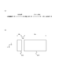
- FIG. 4B shows a modification of the operation of the printing device 12.
- the pattern portion 304 when the pattern portion 304 is added to the left side of the print image corresponding portion 302, a part of the print image should be deleted by that amount or the print image should be moved to the right side. Is possible. Contrary to the illustrated case, when the pattern portion 304 is added to the right side of the print image corresponding portion 302, it is conceivable to delete a part of the print image or move the print image to the left side by that amount. ..
- the inkjet heads 202y to 202k are caused to perform flushing by ejecting ink to the inkjet heads 202y to 202k according to the added pattern.
- the printing device 12 can be considered as a system or the like that can realize a refresh function and a running flash function, for example, by discarding the medium 50.
- the inkjet heads 202y to 202k can be appropriately flushed without using, for example, a maintenance station or a flushing box. Therefore, as the configuration of the printing device 12, for example, a configuration in which flushing performed using the maintenance station or the flushing box during the main scanning operation cannot be performed can be considered. As such a configuration, for example, a configuration in which a maintenance station receives ink (for example, a cap station) cannot move to a position (for example, height) where flushing can be performed during main scanning operation, or a flushing box is installed. It is conceivable to use a configuration that does not exist.
- the pattern width may be increased while reducing the print density of the pattern. Therefore, it is possible to reduce the amount of ink ejected per unit area. Then, in this case, it is conceivable to eject the ink to the portion corresponding to the pattern, for example, as shown by adding reference numerals B to D in FIG.
- FIG. 5 is a diagram for explaining a method of ejecting ink in the case of increasing the width of a pattern while reducing the density of printing the pattern, and shows examples of various patterns formed by dots of the same number of inks. ..
- FIG. 5 for convenience of illustration, examples of various patterns drawn by 16 nozzles corresponding to numbers 1 to 16 circled in the drawing are shown side by side.
- the pattern indicated by reference numeral A is an example in which the print density of the pattern is not reduced.
- the dot spacing dy in the main scanning direction and the dot spacing dx in the sub-scanning direction are minimized to form the pattern with the highest printing density. It can be considered as an example of drawing.
- Minimizing the interval dy and the interval dx means, for example, setting the minimum interval that can be set in one main scanning operation.
- the patterns indicated by reference numerals B to D are examples in which the print density is lower than that of the pattern indicated by reference numeral A.
- the interval dy or the interval dx is made larger than in the case indicated by reference numeral A, and the printing density is lowered.
- the width of the pattern in accordance with the decrease in the print density the same number of ink dots as in the case of attaching the symbol A is formed. According to this structure, it is possible to appropriately perform the flushing while suppressing the density of the pattern to be low.
- the example indicated by the reference numeral B is an example in which the printing density is lowered in the main scanning direction by increasing the dot spacing dy in the main scanning direction.
- the example indicated by the reference numeral C is an example in which the printing density is lowered in the sub-scanning direction by increasing the dot spacing dx in the sub-scanning direction.
- the nozzles that eject ink at the same timing not all nozzles but nozzles at regular intervals (for example, every other nozzle as shown in the drawing) are selected.
- the example indicated by adding the reference symbol D is an example in which the print density is reduced in both the main scanning direction and the sub scanning direction.
- ink is ejected to only some of the nozzles at each timing using a mask or the like that specifies the nozzles that eject ink at each timing, thereby dispersing the dots of the ink forming the pattern. Even in the case of such a configuration, it is possible to appropriately perform the flushing while suppressing the density of the pattern to be low.
- the control unit 120 performs, for example, correction for adding the ejection position corresponding to the pattern to the main scanning data corresponding to all the main scanning operations. Further, depending on the quality required for printing, the characteristics of the ink used, and the like, appropriate printing may be performed without necessarily performing flushing in every main scanning operation. In this case, the control unit 120 may perform, for example, a correction for adding the ejection position corresponding to the pattern to the main scanning data corresponding to the main scanning operation only for some times.
- the inkjet heads 202y to 202k are made to perform flushing only during a specific number of main scanning operations (specific scan times), and thus intermittently. May be flushed. In this case, for example, it is conceivable to cause the inkjet heads 202y to 202k to perform flushing by one main scanning operation every time a predetermined plurality of main scanning operations are performed.
- how to perform flushing may be different for each ink color, for example.
- nozzle missing or the like is likely to occur in some colors of ink
- the pattern to be added in the printing device 12 the case of mainly using the pattern for causing the inkjet heads 202y to 202k to perform the flushing has been described.
- the feature of adding a pattern is generalized, it is also possible to add a pattern used for other purposes in the printing device 12. In this case as well, by adding the pattern to the data after the RIP processing or the like, the ejection position corresponding to the pattern can be more surely specified.
- the printing device 12 can be considered as an inkjet printer or the like that draws a two-dimensional image on the medium 50.
- the printing device 12 a 3D printer (3D printing device) that forms a three-dimensional object.
- an ink layer may be laminated around the modeled object. Further, in this case, if the print density of the pattern is high, it is conceivable that the ink layer is laminated at a higher speed in the pattern portion than in the portion constituting the modeled object. Further, as a result, for example, the ink layer laminated on the pattern portion may contact (interfere) with the inkjet head to affect the operation of modeling.
- a three-dimensional object is formed by the printing device 12, it is preferable to reduce the pattern printing density as described above with reference to FIG. 5, for example.
- flushing and the like can be more appropriately performed while preventing the occurrence of the above-described problems that occur during modeling of a three-dimensional object.
- flushing or the like can be performed more appropriately by lowering the density of printing the pattern.
- the present invention can be suitably used in, for example, a printing system.
Landscapes
- Ink Jet (AREA)
Abstract
インクジェット方式で印刷を行う印刷装置において、メンテナンスの動作等をより適切に行う。 インクジェット方式で印刷を行う印刷装置であって、インクジェットヘッドと、インクジェットヘッドによりインクを吐出する吐出位置を指定することで印刷すべき画像である印刷画像を示す吐出位置指定データに基づいてインクジェットヘッドの動作を制御する制御部とを備え、制御部は、吐出位置指定データに対し、印刷画像に加えて予め設定されたパターンが更に印刷されるように、吐出位置を追加する補正を行い、補正後の吐出位置指定データに基づいて、インクジェットヘッドにインクを吐出させる。
Description
本発明は、印刷装置及び印刷方法に関する。
近年、インクジェット方式で印刷を行う印刷装置であるインクジェットプリンタが広く用いられている。また、従来、インクジェットプリンタにおいて用いるインクジェットヘッドに対するメンテナンスの動作に関し、フラッシングを行う構成が知られている(例えば、特許文献1参照)。フラッシングとは、例えば、インクジェットヘッドのノズルからインクを吐出することでインクジェットヘッドのメンテナンスを行う方法のことである。フラッシングを定期的に行うことにより、例えば、ノズルの近辺でのインクの乾燥や増粘等を防ぐことができる。
インクジェットプリンタにおいてフラッシングを行う場合、例えばインクジェットヘッドに対するメンテナンスを行う構成であるメンテナンスステーションを用い、メンテナンスステーションの位置へインクジェットヘッドを移動させて、インクジェットヘッドにインクを吐出させることが考えられる。また、高い品質での印刷を行おうとする場合、例えば、印刷の動作中にも定期的にフラッシングを行うことが望ましい。そして、この場合、例えば、インクジェットヘッドが行う主走査動作(スキャン動作)でのインクジェットヘッドの移動経路の途中の位置へメンテナンスステーションを移動させて、主走査動作中にフラッシングを行うことが考えられる。また、主走査動作でのインクジェットヘッドの移動経路の途中の位置に、フラッシング時にインクを受けるための構成(例えば、フラッシングボックス)を配設すること等も考えられる。これらのように構成すれば、例えば、所定の位置をインクジェットヘッドが通過するタイミングでフラッシングを行うことで、印刷の動作中に定期的にフラッシングを行うことが可能になる。
しかし、印刷装置の構成によっては、主走査動作でのインクジェットヘッドの移動経路の途中の位置にメンテナンスステーション等を移動することや、このような位置にフラッシングボックス等を配設すること等が難しい場合がある。また、これらが可能な場合にも、印刷に求められる品質等によっては、様々な位置でフラッシングを行うことが望ましい場合がある。そのため、従来、インクジェットプリンタにおいて、フラッシング等のメンテナンスの動作等をより適切に行うことが望まれていた。そこで、本発明は、上記の課題を解決できる印刷装置及び印刷方法を提供することを目的とする。
本願の発明者は、インクジェットヘッドにフラッシングを行わせる方法について、鋭意研究を行った。そして、先ず、印刷対象の媒体(メディア)に対してインクジェットヘッドにインクを吐出させる方法でフラッシングを行うことを考えた。この場合、例えば、印刷すべき画像である印刷画像に加えて所定のパターンを更に印刷するようにインクジェットヘッドの動作を制御することで、インクジェットヘッドにフラッシングを行わせることが考えられる。このように構成すれば、例えば、メンテナンスステーションやフラッシングボックス等を用いることなく、インクジェットヘッドにフラッシングを行わせることができる。
ここで、印刷画像に加えて所定のパターンを印刷する場合、通常、印刷装置に供給するデータとして、印刷画像及び所定のパターンを示すデータを用いることが考えられる。また、この場合、印刷装置の外部のコンピュータ等でこのデータの元になる画像の編集を行うことで、印刷画像及び所定のパターンを示すデータを作成することが考えられる。
しかし、印刷装置において用いるデータの作成時には、通常、印刷画像をそのまま示すデータ(印刷画像データ)に対し、印刷の条件に合わせた画像処理等の様々な処理を行う。より具体的に、この場合、例えば、印刷装置において使用するインクの色数や印刷の解像度等に合わせて、RIP(Raster Image Processor)処理等を行うことが考えられる。そして、このような処理を行った場合、フラッシングを行うために追加したパターンの部分も処理の対象になることで、意図しない変更が行われる場合がある。また、その結果、所望の条件でのフラッシングを行えなくなるおそれがある。
これに対し、本願の発明者は、更なる鋭意研究により、RIP処理等を行う前の画像に対して所定のパターンを追加するのではなく、RIP処理等により生成されるデータに対して、印刷装置において所定のパターンを追加する補正(変更)を行うことを考えた。このように構成すれば、例えば、所望の条件でのフラッシング等をより適切に行うことができる。また、このようにしてパターンを追加する方法については、例えば、フラッシング以外の目的でパターンを追加する場合にも、同様に用いることが可能である。
また、本願の発明者は、更なる鋭意研究により、このような効果を得るために必要な特徴を見出し、本発明に至った。上記の課題を解決するために、本発明は、媒体に対してインクジェット方式で印刷を行う印刷装置であって、インクジェット方式で前記媒体へインクを吐出するインクジェットヘッドと、前記インクジェットヘッドによりインクを吐出する吐出位置を指定することで印刷すべき画像である印刷画像を示す吐出位置指定データに基づいて前記インクジェットヘッドの動作を制御する制御部とを備え、前記制御部は、前記吐出位置指定データに対し、前記印刷画像に加えて予め設定されたパターンが更に印刷されるように、前記吐出位置を追加する補正を行い、補正後の前記吐出位置指定データに基づいて、前記インクジェットヘッドにインクを吐出させる。
このように構成した場合、例えば、印刷画像に対して所定のパターンを追加することにより、インクジェットヘッドにフラッシング等を行わせることができる。また、この場合において、吐出位置を指定するデータに対して補正を行うことにより、例えば、フラッシング等のためにインクを吐出する位置をより確実かつ適切に指定することができる。
また、この場合、媒体へインクを吐出することで、例えばメンテナンスステーションやフラッシングボックス等を用いることなく、インクジェットヘッドにフラッシング等を行わせることができる。そのため、このように構成すれば、例えば、インクジェット方式で印刷を行う印刷装置(インクジェットプリンタ)において、フラッシング等のメンテナンスの動作等をより適切に行うことができる。
また、より具体的に、この構成において、インクジェットヘッドにインクを吐出させるとは、例えば、インクジェットヘッドにおける各ノズルにインクを吐出させることである。また、上記のパターンとしては、インクジェットヘッドにフラッシングを行わせるためのパターンを用いることが考えられる。この場合、パターンとして、例えば、媒体において印刷画像と重ならない吐出位置へインクジェットヘッドにインクを吐出させるパターンを用いることが考えられる。このように構成すれば、例えば、インクジェットヘッドにフラッシングを適切に行わせることができる。
また、吐出位置指定データとしては、例えば、印刷画像を示すデータに対してRIP処理を行うことで生成されたデータ等を好適に用いることができる。このように構成すれば、例えば、フラッシングを行う条件がRIP処理によって変化すること等を適切に防ぐことができる。
また、この構成において、印刷装置は、例えば、媒体において印刷画像が印刷される領域の各位置に対して複数回の主走査動作を行うマルチパス方式で媒体への印刷を行う。この場合、印刷装置は、例えば、パス数をN(Nは、2以上の整数)とするマルチパス方式で媒体への印刷を行う。また、主走査動作とは、例えば、予め設定された主走査方向へ媒体に対して相対的に移動しつつインクを吐出する動作のことである。また、この場合、印刷装置は、例えば、主走査動作をインクジェットヘッドに行わせる主走査駆動部と、副走査動作をインクジェットヘッドに行わせる副走査駆動部とを更に備える。副走査動作とは、例えば、主走査方向と直交する副走査方向へ媒体に対して相対的に移動する動作のことである。
また、マルチパス方式で印刷を行う場合、例えばRIP処理を行う前のデータに対して所定のパターンを追加すると、その後に行う処理により、パターンに対応する部分についても、マルチパス方式で印刷を行うことになる。そして、この場合、各回の主走査動作でパターンに対応する位置へ吐出するインクの量は、パス数に応じて減少することになる。そのため、このようにしてパターンを追加した場合、所望の条件でのフラッシング等を行うことが難しくなる場合がある。
これに対し、吐出位置指定データの補正によりパターンを追加する場合、各回の主走査動作でインクを吐出する吐出位置を直接的に指定することができる。また、より具体的に、例えば、1回の主走査動作においてインクジェットヘッドによりインクを吐出する吐出位置を指定するデータを主走査用データと定義した場合、吐出位置指定データとしては、例えば、印刷画像を印刷するために行うそれぞれの回の主走査動作に対応する主走査用データを含むデータを用いることが考えられる。そして、この場合、制御部は、例えば、少なくともいずれかの回の主走査動作に対応する主走査用データに対し、パターンに対応する吐出位置を追加する補正を行う。このように構成すれば、例えば、所望の条件でのフラッシング等をより適切に行うことができる。
ここで、パターンの追加によりインクジェットヘッドにフラッシングを行わせる場合、例えば、全ての回の主走査動作においてフラッシングを行わせることが考えられる。この場合、制御部は、例えば、全ての回の主走査動作に対応する主走査用データに対し、パターンに対応する吐出位置を追加する補正を行う。また、印刷に求められる品質や、使用するインク等の特性によっては、必ずしも全ての回の主走査動作でフラッシングを行わなくても、適切に印刷を行える場合もある。この場合、制御部は、例えば、一部の回のみの主走査動作に対応する主走査用データに対し、パターンに対応する吐出位置を追加する補正を行ってもよい。
また、マルチパス方式での動作に関し、印刷の解像度に応じて設定される全ての吐出位置に対してインクを吐出する場合の印刷の濃度を全吐出濃度Mdと定義した場合、パターンに対応する吐出位置を追加する補正を行う前の主走査用データについては、パス数に応じて印刷の濃度が全吐出濃度Mdよりも低くなっているデータ等と考えることができる。また、より具体的に、補正前の主走査用データについては、例えば、全吐出濃度Mdをパス数Nで除した数であるMd/N以下に印刷の濃度がなるように吐出位置を指定するデータ等と考えることができる。
これに対し、補正により追加したパターンに対応する部分では、このような印刷の濃度よりも印刷の濃度が高くなるようにインクを吐出することが考えられる。この場合、制御部は、例えば、少なくともいずれかの回の主走査動作に対応する主走査用データに対し、1回の主走査動作においてパターンに対応する位置へ吐出されるインクによる印刷の濃度がMd/Nよりも大きくなるように、パターンに対応する吐出位置を追加する補正を行う。このように構成すれば、例えば、マルチパス方式で印刷画像の印刷を行う場合にも、パターンに対応する部分に対し、より高い印刷の濃度でインクジェットヘッドにインクを吐出させることができる。
また、この構成において、主走査用データとしては、例えば、対応する主走査動作においてインクを吐出する吐出位置が画素と対応付けられたラスタ画像のデータを用いることが考えられる。また、この場合、印刷装置は、例えば、少なくとも次に行う主走査動作に対応する主走査用データが示すラスタ画像を記憶する画情報記憶部を更に備える。画情報記憶部としては、例えば、公知の画像記憶用のメモリ(画情報メモリ)等を好適に用いることができる。また、この場合、制御部は、例えば、画情報記憶部に記憶されているラスタ画像に対し、パターンに対応する位置の画素の値を変更する補正を行う。このように構成すれば、例えば、主走査用データに対して、パターンに対応する吐出位置を追加する補正を適切に行うことができる。
また、吐出位置指定データの補正時には、単にパターンに対応する吐出位置の追加を行うのではなく、吐出位置を追加するための領域の確保を行った上で、パターンに対応する吐出位置の追加を行うことも考えられる。また、このような領域の確保の方法としては、例えば、印刷画像が印刷される位置の変更や、印刷画像の一部を削除する処理等を行うことが考えられる。より具体的に、主走査用データに対してパターンに対応する吐出位置を追加する補正において、制御部は、例えば、媒体において印刷画像が印刷される位置の変更を行った上で、媒体において印刷画像と重ならないように、パターンに対応する吐出位置を追加する。また、主走査用データに対してパターンに対応する吐出位置を追加する補正において、制御部は、例えば、印刷画像の一部を削除した上で、印刷画像から削除した一部に対応する範囲内に、パターンに対応する吐出位置を追加してもよい。これらのように構成すれば、例えば、吐出位置指定データの補正をより適切に行うことができる。
また、この構成において、制御部は、例えば、印刷装置の外部にある装置から吐出位置指定データを受け取る。この場合、印刷装置の外部にある装置とは、例えば、印刷装置の動作を制御するコンピュータ等のことである。そして、この場合、制御部は、例えば、印刷装置内で、吐出位置指定データに対し、パターンが更に印刷されるように吐出位置を追加する補正を行う。このように構成すれば、例えば、印刷画像を示すデータを印刷装置に提供した後に、パターンを追加する処理等を適切に行うことができる。
また、この構成において、印刷装置は、例えば、印刷装置の動作を制御するプログラムであるファームウェアを記憶するファームウェア記憶部を更に備える。この場合、制御部は、例えば、ファームウェア記憶部に記憶されているファームウェアに従って、吐出位置指定データに対する補正を行う。このように構成すれば、例えば、印刷装置内において、吐出位置指定データの補正を適切に行うことができる。
また、この構成において、制御部では、例えば、どのようなパターンを追加するかについて、ユーザの指示に応じて決定することが考えられる。この場合、制御部は、例えば、パターンの幅、及びパターンの形成時にインクを吐出する印刷の濃度の指定をユーザから受け取る。そして、ユーザの指定に基づき、吐出位置指定データに対し、パターンが更に印刷されるように吐出位置を追加する補正を行う。このように構成すれば、例えば、ユーザの指示に応じて、追加するパターンを様々に変化させることができる。また、これにより、例えば、必要に応じて、フラッシングの条件等を様々に変化させることができる。
また、本発明の構成として、上記と同様の特徴を有する印刷方法等を用いることも考えられる。この場合も、例えば、上記と同様の効果を得ることができる。
本発明によれば、例えば、インクジェット方式で印刷を行う印刷装置において、メンテナンスの動作等をより適切に行うことができる。
以下、本発明に係る実施形態を、図面を参照しながら説明する。図1は、本発明の一実施形態に係る印刷システム10について説明をする図である。図1(a)は、印刷システム10の構成の一例を示す。尚、以下において説明をする点を除き、本例の印刷システム10は、公知の印刷システムと同一又は同様の特徴を有してよい。
本例において、印刷システム10は、印刷対象の媒体(メディア)に対してインクジェット方式で印刷を行うシステムであり、印刷装置12及びホストPCを備える。印刷装置12は、インクジェット方式で媒体に対して印刷を行うインクジェットプリンタであり、ホストPC14から受け取る印刷入力データに基づき、印刷の動作を実行する。この場合、印刷入力データとは、例えば、印刷すべき画像である印刷画像を示す入力データのことである。また、本例において、印刷入力データは、吐出位置指定データの一例である。この場合、吐出位置指定データとは、例えば、印刷装置12におけるインクジェットヘッドによりインクを吐出する吐出位置を指定することで印刷画像を示すデータのことである。
ホストPC14は、印刷装置12の動作を制御するコンピュータであり、印刷装置12の外部において印刷入力データを生成して、生成した印刷入力データを印刷装置12へ供給することにより、印刷装置12の動作を制御する。また、より具体的に、本例において、ホストPC14は、RIP(Raster Image Processor)処理を行うことで、印刷入力データを生成する。この場合、RIP処理とは、例えば、印刷装置12において使用するインクの色数や印刷の解像度等に合わせたラスタ形式の画像を生成する処理のことである。ホストPC14から印刷装置12へ供給する印刷入力データとしては、公知のRIP処理等を行って生成するデータを好適に用いることができる。この場合、ホストPC14において印刷入力データを生成する処理については、例えば、公知の処理と同一又は同様に行うことができる。また、印刷入力データを生成する処理等については、後に更に詳しく説明をする。
続いて、印刷システム10における印刷装置12について、更に詳しく説明をする。図1(b)は、印刷装置12の構成の一例を示す。図1(c)は、印刷装置12におけるヘッド部102の構成の一例を示す。本例において、印刷装置12は、ヘッド部102、プラテン104、主走査駆動部106、副走査駆動部108、画情報メモリ110、ファームウェア記憶部112、及び制御部120を有する。
尚、上記及び以下に説明をする点を除き、印刷装置12は、公知のインクジェットプリンタと同一又は同様の特徴を有してよい。また、印刷装置12は、図示した構成以外に、印刷の動作等に必要な各種の構成を更に有してもよい。例えば、印刷装置12は、使用するインクの種類に応じて、インクを媒体50に定着させるための定着手段等を更に有してよい。
ヘッド部102は、媒体50に対してインクを吐出する部分である。また、本例において、ヘッド部102は、図1(c)にインクジェットヘッド202y、インクジェットヘッド202m、インクジェットヘッド202c、及びインクジェットヘッド202k(以下、インクジェットヘッド202y~kという)として示すように、複数のインクジェットヘッドを有する。この場合、インクジェットヘッド202y~kのそれぞれは、互いに異なる色のインクをインクジェット方式で媒体50へ吐出するインクジェットヘッドであり、印刷装置12において予め設定された副走査方向(図中のX方向)の位置をずらして並ぶ複数のノズルを有し、それぞれのノズルから、媒体50へ向けて、インクを吐出する。また、本例において、インクジェットヘッド202y~kは、副走査方向の位置を揃えて、副走査方向と直交する主走査方向(図中のY方向)へ並べて配設される。
また、インクジェットヘッド202y~kから吐出する各色のインクは、カラー印刷(例えば、フルカラー印刷)に用いる基本色(プロセスカラー)の各色のインクである。より具体的に、インクジェットヘッド202yは、イエロー色(Y色)のインクを吐出する。インクジェットヘッド202mは、マゼンタ色(M色)のインクを吐出する。インクジェットヘッド202cは、シアン色(C色)のインクを吐出する。また、インクジェットヘッド202kは、ブラック色(K色)のインクを吐出する。
プラテン104は、ヘッド部102と対向する位置において媒体50を保持する台状部材である。主走査駆動部106は、ヘッド部102におけるインクジェットヘッド202y~kに主走査動作を行わせる駆動部である。この場合、主走査動作とは、主走査方向へ媒体50に対して相対的に移動しつつインクを吐出する動作のことである。本例において、主走査駆動部106は、例えば、主走査方向における位置を固定した媒体50に対してインクジェットヘッド202y~kの側を主走査方向へ移動させることにより、インクジェットヘッド202y~kに主走査動作を行わせる。
副走査駆動部108は、インクジェットヘッド202y~kに副走査動作を行わせる駆動部である。この場合、副走査動作とは、副走査方向へ媒体50に対して相対的に移動する動作のことである。また、本例において、副走査駆動部108は、例えば、図示を省略したローラ等を用いて副走査方向と平行な搬送方向へ媒体50を搬送することにより、媒体50の側を移動させて、インクジェットヘッド202y~kに副走査動作を行わせる。
画情報メモリ110は、画情報記憶部の一例として機能する画像記憶用のメモリであり、主走査動作においてインクを吐出する位置を示すラスタ画像を記憶する。また、ファームウェア記憶部112は、印刷装置12の動作を制御するプログラムであるファームウェアを記憶する記憶部である。
制御部120は、例えば印刷装置12のCPUを含む構成であり、ファームウェア記憶部112に記憶されているファームウェアに従って動作をすることにより、印刷装置12の各部の動作を制御する。より具体的に、制御部120は、ホストPC14から受け取る印刷入力データに基づき、インクジェットヘッド202y~kの動作を制御する。また、この場合、制御部120は、例えば、印刷入力データに基づき、少なくとも各回の主走査動作が行われる前に、その回の主走査動作においてインクを吐出する位置を示すラスタ画像を画情報メモリ110に記憶させる。また、更に具体的に、複数回の主走査動作を繰り返して行う印刷の動作中において、制御部120は、例えば、ホストPC14から受け取る印刷入力データに基づき、少なくとも、次の回の主走査動作においてインクを吐出する位置を示すラスタ画像を画情報メモリ110に記憶させる。これにより、各回の主走査動作において、制御部120は、画情報メモリ110に記憶されているラスタ画像に基づき、インクジェットヘッド202y~kに対し、インクを吐出する吐出位置の制御を行う。本例によれば、例えば、印刷入力データが示す印刷画像の印刷を適切に行うことができる。
ここで、本例において、印刷装置12は、マルチパス方式により、媒体50への印刷を行う。この場合、マルチパス方式とは、媒体50において印刷画像が印刷される領域の各位置に対して複数回の主走査動作を行う方式のことである。各位置に対して複数回の主走査動作を行うとは、各位置と対向する位置をインクジェットヘッド202y~kが通過する回数が複数回になるように主走査動作を行うことである。また、この場合、各回の主走査動作の合間において、副走査駆動部108は、各位置に対して行う主走査動作の回数であるパス数に応じて決まる送り量での副走査動作をインクジェットヘッド202y~kに行わせる。より具体的に、インクジェットヘッド202y~kのそれぞれにおいてノズルが存在する範囲の副走査方向における幅をノズル長Lと定義して、パス数をN(Nは、2以上の整数)とした場合、副走査動作での送り量については、例えば、ノズル長をNで除した値(L/N)に対応する距離に設定することが考えられる。
また、本例において、ホストPC14は、印刷装置12において行うマルチパス方式での動作に合わせて、各回の主走査動作でインクを吐出する吐出位置を示す印刷入力データを生成する。より具体的に、例えば、1回の主走査動作においてインクジェットヘッド202y~kのそれぞれによりインクを吐出する吐出位置を指定するデータを主走査用データと定義した場合、ホストPC14は、印刷画像を印刷するために行うそれぞれの回の主走査動作に対応する主走査用データを含む印刷入力データを生成する。この場合、主走査用データについては、例えば、一つのインクジェットヘッドにより1回の主走査動作でインクを吐出する吐出位置を示すデータ等と考えることができる。
また、このような主走査用データを含む印刷入力データについては、例えば、印刷に使用するインクの色毎に各回の主走査動作でインクを吐出する吐出位置を示すデータ等と考えることができる。そして、この場合、主走査用データについては、例えば、吐出位置を指定することで吐出位置に対応する画像を示すラスタ画像と考えることもできる。また、この場合、画情報メモリ110については、例えば、各回の主走査動作に対応するラスタ画像を記憶すると考えることができる。この場合、画情報メモリ110は、少なくとも、次に行う主走査動作に対応する主走査用データが示すラスタ画像を記憶する。
また、本例において、制御部120は、画情報メモリ110に記憶されているラスタ画像に対し、所定のパターンを追加する補正を行う。この場合、所定のパターンを追加する補正とは、例えば、各回の主走査動作において所定のパターンに対応する吐出位置に更にインクが吐出されるように行う補正のことである。
また、より具体的に、本例においては、このように追加するパターンとして、インクジェットヘッド202y~kにフラッシングを行わせるためのパターンを用いる。フラッシングについては、後に更に詳しく説明をする。また、この場合、制御部120は、例えば、少なくともいずれかの回の主走査動作に対応する主走査用データに対し、パターンに対応する吐出位置を追加する補正を行う。これにより、制御部120は、印刷入力データに対し、印刷画像に加えて予め設定されたパターンが更に印刷されるように、吐出位置を追加する補正を行う。そして、補正後の印刷入力データに基づいて、インクジェットヘッド202y~kにインクを吐出させる。この場合、インクジェットヘッド202y~kにインクを吐出させるとは、例えば、インクジェットヘッド202y~kのそれぞれにおける各ノズルにインクを吐出させることである。また、補正後の印刷入力データとは、例えば、印刷装置12への入力時の印刷入力データが含む主走査用データを上記又は以下において説明をするようにして補正を行った補正後の主走査用データに置き換えたデータのことである。また、補正後の印刷入力データに基づくとは、例えば、補正後の主走査用データに基づくことであってよい。また、所定のパターンを追加する補正については、以下において、更に詳しく説明をする。
図2は、制御部120(図1参照)により行う所定のパターンを追加する補正について更に詳しく説明をする図である。上記においても説明をしたように、本例において、印刷装置12(図1参照)は、印刷装置12の外部にある装置であるホストPC14(図1参照)から印刷入力データを受け取る。そして、ファームウェア記憶部112(図1参照)に記憶されているファームウェアに従って制御部120により補正の動作を実行することで、印刷装置12内において、印刷画像を印刷するためのインクの吐出位置を示す印刷入力データに対し、所定のパターンが更に印刷されるように吐出位置を追加する補正を行う。このように構成すれば、例えば、印刷画像を示す印刷入力データを印刷装置12に提供した後に、パターンを追加する処理等を適切に行うことができる。
図2(a)は、パターンを追加する処理の一例を示す図であり、インクジェットヘッド202y~k(図1参照)により1回の主走査動作で媒体50上に描く画像の一例を示す。また、図2(a)については、例えば、画情報メモリ110に記憶されているラスタ画像に基づいてインクジェットヘッド202y~kが1回の主走査動作でインクを吐出することで描く画像の範囲等を示していると考えることができる。この場合、画情報メモリ110に記憶されているラスタ画像とは、パターンを追加する補正を行った後のラスタ画像のことである。
上記においても説明をしたように、本例において、印刷装置12は、印刷画像を印刷するために行うそれぞれの回の主走査動作に対応する主走査用データを含む印刷入力データをホストPC14から受け取る。この場合、各回の主走査動作に対応する主走査用データについて、印刷画像の一部に対応するラスタ画像を示すと考えることができる。また、このような主走査用データについては、例えば、対応する主走査動作においてインクを吐出する吐出位置が画素と対応付けられたラスタ画像のデータ等と考えることができる。また、このラスタ画像については、例えば、その回の主走査動作においてインクを吐出する吐出位置を示す画像等と考えることもできる。
また、上記においても説明をしたように、制御部120は、例えば、印刷入力データに基づき、各回の主走査動作が行われる前に、その回の主走査動作においてインクを吐出する位置を示すラスタ画像を画情報メモリ110に記憶させる。また、本例において、制御部120は、更に、画情報メモリ110に記憶されているラスタ画像を補正することで、所定のパターンを追加する。この場合、ラスタ画像の補正により所定のパターンを追加するとは、その回の主走査動作で所定のパターンに対応する吐出位置にインクが吐出されるようにラスタ画像を補正することである。また、より具体的に、本例において、制御部120は、例えば、画情報メモリ110に記憶されているラスタ画像に対し、パターンに対応する位置の画素の値を変更する補正を行う。また、より具体的に、この場合、画素の値について、インクを吐出することを示す値に変更することが考えられる。このように構成すれば、例えば、主走査用データに対して、パターンに対応する吐出位置を追加する補正を適切に行うことができる。
そして、このような補正を行った後において、画情報メモリ110は、例えば、図中に示す印刷画像対応部302及びパターン部304に対応する領域を含むラスタ画像を記憶する。また、より具体的に、本例において、画情報メモリ110は、例えば、インクの色毎に分版されたラスタ画像を記憶する。そして、この場合、画情報メモリ110は、各色に対応するラスタ画像における印刷画像対応部302及びパターン部304に対応する領域に、1色分のインクの吐出位置に対応する画像を記憶する。
また、この場合、印刷画像対応部302は、印刷画像に対応する部分であり、印刷画像のうち、その回の主走査動作においてインクを吐出する部分を示す。印刷画像対応部302については、例えば、補正前のラスタ画像に対応する部分等と考えることもできる。また、図中に示す場合において、印刷画像対応部302の主走査方向(Y方向)における幅は、Waである。幅Waは、例えば、印刷画像の幅に応じて設定される。また、副走査方向(X方向)における幅は、インクジェットヘッドのノズル長に対応する幅になっている。
また、パターン部304は、補正により追加するパターンに対応する部分である。図中に示す場合において、パターン部304は、印刷画像対応部302との間に空白部を挟んで、主走査方向における印刷画像対応部302の両側に追加される。図中に示す場合において、パターン部304の主走査方向における幅は、Wbである。また、副走査方向における幅は、インクジェットヘッドのノズル長に対応する幅になっている。また、印刷画像対応部302とパターン部304と間の空白部の幅(主走査方向における幅)は、Wcである。パターン部304の幅Wbや、空白部の幅Wcについては、例えば、追加するパターンを指定するユーザの指示等に応じて設定することが考えられる。
尚、パターン部304を追加する補正を行った場合、各回の主走査動作においてインクジェットヘッド202y~kを移動させる範囲(主走査方向における幅)についても、補正の結果に応じて広げることが考えられる。このように構成すれば、パターンを追加した結果に合わせて、適切に印刷を行うことができる。
続いて、本例において補正により追加するパターンについて、更に詳しく説明をする。図2(b)は、パターン部304の構成の一例を示す。上記においても説明をしたように、本例において、印刷装置12は、ホストPC14から受け取る印刷入力データに対し、パターンを追加する補正を行う。また、これにより、媒体50に対し、印刷画像に加えて、パターンを印刷する。
そして、本例においては、このように追加するパターンとして、上記においても説明をしたように、インクジェットヘッド202y~kにフラッシングを行わせるためのパターンを用いる。この場合、フラッシングとは、インクジェットヘッドのノズルから定期的にインクを吐出することでインクジェットヘッドのメンテナンスを行う方法のことである。フラッシングを定期的に行うことにより、例えば、インクジェットヘッドにおけるノズルの近辺でのインクの乾燥や増粘等を適切に防ぐことができる。また、フラッシングを行わせるためのパターンについては、例えば、印刷画像の印刷以外の目的でインクをインクジェットヘッドに吐出させるための捨て打ちパターン等と考えることもできる。フラッシングを行わせるためのパターンとしては、例えば、インクジェットヘッド202y~kのそれぞれにおける全てのノズルで描くはしご状のパターン等を好適に用いることができる。
また、より具体的に、本例において、印刷装置12の制御部120は、例えば図2(a)に示すように、印刷画像対応部302と重ならない位置にパターン部304を追加する。そして、パターン部304を描くためにインクを吐出する動作を利用して、フラッシングを行う。そのため、本例において追加するパターンについては、例えば、媒体50において印刷画像と重ならない吐出位置へインクジェットヘッド202y~kにインクを吐出させるパターン等と考えることができる。また、更に具体的に、本例において、パターン部304に形成するパターンとしては、例えば図2(b)に示すように、互いに異なる色の複数の領域402により構成されるカラーバー状のパターンを用いる。図2(b)においては、図示の便宜上、異なる色について、異なる網掛け模様で示している。また、本例において、複数の領域402は、パターン部304の中で主走査方向における一部を構成する領域である。そのため、それぞれの領域402の副走査方向における幅は、インクジェットヘッドのノズル長に対応する幅になっている。このように構成すれば、各回の主走査動作において、領域402に対し、例えば、インクジェットヘッドの全てのノズルからインクを吐出することが可能になる。
また、各回の主走査動作において、制御部120は、例えば、インクジェットヘッド202y~kのそれぞれについて、全てのノズルから複数回インクを吐出させる。このように構成すれば、例えば、各回の主走査動作において、インクジェットヘッド202y~kのそれぞれに対してフラッシングを適切に行わせることができる。また、この場合、例えば、少なくともいずれかの一つの領域402に対し、一つのインクジェットヘッドの全てのノズルから複数回インクを吐出させることが考えられる。
本例によれば、例えば、印刷画像に対して所定のパターンを追加することにより、インクジェットヘッド202y~kにフラッシングを適切に行わせることができる。また、この場合において、吐出位置を指定するデータに対して補正を行うことにより、例えば、フラッシング等のためにインクを吐出する位置をより確実かつ適切に指定することができる。また、この場合、媒体50へインクを吐出することで、例えばメンテナンスステーションやフラッシングボックス等を用いることなく、インクジェットヘッド202y~kにフラッシングを適切に行わせることができる。
続いて、パターン部304(図2参照)に含まれる領域402の特徴について更に詳しく説明をする。図3は、領域402の特徴について更に詳しく説明をする図である。図3(a)は、パターン部304における一つの領域402の詳細な構成の一例を示す図であり、同じ色(1カラー)で塗りつぶされる一つの領域402について、その領域402を構成するインクのドット502の並び方の例を示す。図3(b)は、一つの領域402内において近接して形成される複数のドット502の位置関係を拡大して示す。
図中に示すように、領域402において、インクのドット502は、主走査方向及び副走査方向へ並べて形成される。また、図3(a)に図示した場合において、一つの領域402の主走査方向における幅は、Wdである。また、本例において、領域402内の複数のドット502は、主走査方向及び副走査方向における間隔を一定にして並ぶ。より具体的に、複数のドット502は、例えば図3(b)に示すように、主走査方向における間隔をdyとし、副走査方向における間隔をdxとして、一定の間隔で並ぶ。この場合、主走査方向における間隔dyは、主走査動作時に一つノズルからインクを吐出する間隔(時間の間隔)と、主走査動作時におけるインクジェットヘッドの移動速度とに応じて決まる。また、副走査方向における間隔dxは、一つのインクジェットヘッドの中での副走査方向におけるノズル間の間隔(距離の間隔)に応じて決まる。
ここで、媒体50上にインクジェットヘッド202y~kにインクを吐出させることでフラッシングを行わせる場合、通常、より多くのインクを吐出させる程、フラッシングの効果が大きくなる。また、この場合、例えば、パターン部304におけるそれぞれの領域402を構成するインクのドット502の密度を調整することで、フラッシング時のインクの吐出量を調整することができる。また、より具体的に、本例においては、例えば、一つの領域402の主走査方向における幅Wdや、領域402内での主走査方向におけるドット502の間隔dyを変化させることで、フラッシング時のインクの吐出量を変化させることが可能である。
そのため、本例において、印刷装置12(図1参照)は、ユーザの指示に応じてこれらのパラメータを設定することで、フラッシング時のインクの吐出量を調整する。より具体的に、この場合、印刷装置12における制御部120は、例えば、パターンの幅、及びパターンの形成時にインクを吐出する印刷の濃度等の指定をユーザから受け取る。この場合、パターンの幅とは、パターン部304の副走査方向における幅Wbのことである。パターンの幅を指定することで、例えば、フラッシング時のインクの吐出量等の制御(フラッシングの制御)を行うことができる。また、制御部120は、パターンの幅を示すパラメータとして、例えば、一つの領域402の幅Wdの指定をユーザから受け取ってもよい。
また、印刷の濃度については、例えば、フラッシング時のインクの吐出量と予め対応付けられたレベル(以下、リフレッシュレベルという)の指定をユーザから受け取ることが考えられる。この場合、例えば、互いに異なる吐出量と対応付けられた複数段階のリフレッシュレベルからいずれかをユーザに選択させることで、印刷の濃度の指定をユーザから受け取ることが考えられる。また、この場合、パターンの印刷の濃度(パターンの濃度)を指定することにより、例えば、フラッシングの量及び連続性の制御を行うことができる。
また、この場合、制御部120は、例えば、ユーザの指示に応じて、印刷入力データを構成する主走査用データに対し、指定された条件に合わせたパターンが更に印刷されるように、吐出位置を追加する補正を行う。この場合、例えば、指定されたパターンの幅及びリフレッシュレベルに応じて、それぞれの領域402の幅や主走査方向におけるドット502間の距離dy等を調整することで、追加すべき吐出位置を決定することが考えられる。このように構成すれば、例えば、どのようなパターンを追加するかについて、ユーザの指示に応じて適切に決定することができる。また、追加するパターンを様々に変化させることで、例えば、必要に応じて、フラッシングの条件等を様々に変化させることができる。そのため、本例によれば、例えば、所望の条件でのフラッシングをより適切に行うことができる。
続いて、パターンを追加する補正等について更に詳しく説明をする。図4は、パターンを追加する補正等について更に詳しく説明をする図である。図4(a)は、印刷システム10において行うデータ処理等について更に詳しく説明をする図である。
上記においても説明をしたように、本例の印刷システム10では、ホストPC14において、RIP処理を行うことで、印刷入力データを生成する。より具体的に、本例において、ホストPC14は、印刷画像を示すデータである印刷画像データに対し、RIP処理等を行うことで、印刷入力データを生成する。この場合、印刷画像データとしては、例えば、印刷装置12に依存しない形式(例えば汎用の画像形式)のカラー画像のデータ等を用いることが考えられる。また、印刷画像データは、多階調のカラー画像のデータであってよい。
そして、ホストPC14は、印刷画像データに対し、RIP処理を行う。また、この処理において、より具体的に、ホストPC14は、例えば、印刷装置12において使用するインクの色に合わせた色変換処理及び分版処理、印刷装置12における印刷の解像度に合わせた解像度変換処理、及び量子化処理等を行う。また、ホストPC14は、更に、これらの処理を行った後の画像を印刷装置12で処理可能な形式に変換するコマンド化を行って、印刷入力データを生成する。また、この場合、上記の処理におけるいずれかの段階(例えば、コマンド化の処理時)において、印刷のパス数に応じて設定されるマスクを用いて、印刷のパス数に合わせてデータを分ける処理を行う。また、これにより、各回の主走査動作時のインクの吐出位置を指定する主走査用データを含む印刷入力データを生成する。
また、このようにして生成された印刷入力データに対し、印刷装置12では、上記においても説明をしたように、パターンを追加する補正を行う。また、これにより、図中にパターン追加データと示すように、補正後の印刷入力データを生成する。そして、補正後の印刷入力データに従って印刷の動作を実行することで、印刷画像を描くために行う主走査動作の中で、フラッシングを行う。
ここで、印刷に用いるデータに対して所定のパターンを追加することを考えた場合、印刷装置12においてRIP処理後のデータに対して処理をするのではなく、例えばRIP処理等を行う前の段階でパターンを追加すればよいようにも思われる。しかし、このようにしてパターンを追加した場合、パターンの部分に対しても印刷画像の部分と同じようにその後の処理が行われることで、パターンに対応する部分についても、マルチパス方式で印刷を行うことになる。より具体的に、この場合、パターンに対応する部分に対しても、印刷のパス数に応じて設定されるマスクが適用されることになる。また、その結果、各回の主走査動作でパターンに対応する位置へ吐出するインクの量についても、パス数に応じて減少することになる。そのため、このようにしてパターンを追加した場合、所望の条件でのフラッシング等を行うことが難しくなる場合がある。
これに対し、本例においては、印刷入力データに対する補正によりパターンを追加することで、パターンに対応する位置について、各回の主走査動作時でインクを吐出する吐出位置を直接的に指定することができる。また、これにより、例えば、フラッシングを行う条件がRIP処理によって変化すること等を適切に防ぎ、所望の条件でのフラッシングをより適切に実行することができる。
また、より具体的に、マルチパス方式に関連する事項に関し、印刷の解像度に応じて設定される全ての吐出位置に対してインクを吐出する場合の印刷の濃度を全吐出濃度Mdと定義した場合、パターンに対応する吐出位置を追加する補正を行う前の主走査用データについては、例えば、パス数に応じて印刷の濃度が全吐出濃度Mdよりも低くなっているデータになっていると考えることができる。例えば、印刷のパス数をNとした場合、補正前の主走査用データでは、全吐出濃度Mdをパス数Nで除した数であるMd/N以下に印刷の濃度がなるように吐出位置が指定されることになる。
これに対し、補正により追加したパターンに対応する部分では、パス数と無関係に吐出位置を指定することが可能であるため、このような印刷の濃度よりも印刷の濃度が高くなるようにインクの吐出位置を指定することができる。より具体的に、例えば、印刷装置12の制御部120(図1参照)では、少なくともいずれかの回の主走査動作に対応する主走査用データに対し、1回の主走査動作においてパターンに対応する位置へ吐出されるインクによる印刷の濃度がMd/Nよりも大きくなるように、パターンに対応する吐出位置を追加する補正を行うことが考えられる。このように構成すれば、例えば、マルチパス方式で印刷画像の印刷を行う場合にも、パターンに対応する部分に対し、より高い印刷の濃度でインクジェットヘッドにインクを吐出させることができる。
尚、上記のように、本例においては、パターンに対応する部分に対し、高い印刷の濃度で適切にインクジェットヘッドにインクを吐出させることができる。しかし、この場合において、印刷の濃度を高くしすぎると、媒体の特性等に応じて決まるインクの許容量を超えること等も考えられる。より具体的に、例えば、印刷画像の印刷を多くのパス数で行うことが必要になる印刷の条件の場合、上記の濃度Md/Nと比べて高すぎる印刷の濃度でパターンに対応する位置へインクを吐出すると、媒体上のインクが過剰になることで、様々な問題(例えば、コックリング等)が生じること等も考えられる。そのため、このような場合には、例えば、パターンの印刷の濃度を下げつつパターンの幅を大きくすること等が考えられる。このように構成すれば、例えば、フラッシングを行うために必要な吐出量を確保しつつ、このような問題の発生を適切に防ぐことができる。
続いて、パターンを追加する位置等について、更に詳しく説明をする。上記においても説明をしたように、本例においては、印刷装置12の制御部120により印刷入力データの補正を行うことにより、インクジェットヘッド202y~k(図1参照)にフラッシングを行わせるためのパターンを追加する。そして、この補正時には、単にパターンに対応する吐出位置の追加を行うのではなく、吐出位置を追加するための領域の確保を行った上で、パターンに対応する吐出位置の追加を行うことも考えられる。また、このような領域の確保の方法としては、例えば、印刷画像が印刷される位置の変更や、印刷画像の一部を削除する処理等を行うことが考えられる。
より具体的に、印刷入力データを構成する主走査用データに対してパターンに対応する吐出位置を追加する補正において、制御部120は、例えば、媒体において印刷画像が印刷される位置の変更を行った上で、媒体において印刷画像と重ならないように、パターンに対応する吐出位置を追加する。また、この場合、印刷装置12としては、例えば、印刷画像を任意の位置に移動可能なシステムを用いることが考えられる。このように構成すれば、例えば、各回の主走査動作に対応する主走査用データに対し、パターンを任意の位置に追加することができる。また、これにより、例えば、印刷入力データの補正を適切に行い、各回の主走査動作に対するパターンの付与を適切に行うことができる。
また、主走査用データに対してパターンに対応する吐出位置を追加する補正において、制御部120は、例えば、印刷画像の一部を削除した上で、印刷画像から削除した部分に対応する範囲内に、パターンに対応する吐出位置を追加してもよい。このように構成した場合も、例えば、印刷入力データの補正を適切に行い、各回の主走査動作に対するパターンの付与を適切に行うことができる。
また、上記においては、パターンを追加する位置について、図2等を用いて、印刷画像対応部302に対する主走査方向の両側にパターン部304を追加する例を説明した。しかし、印刷装置12の動作の変形例においては、例えば図4(b)に示すように、印刷画像対応部302の片側(印刷画像対応部302の右側又は左側の片方)のみにパターン部304を追加してもよい。図4(b)は、印刷装置12の動作の変形例を示す。
より具体的に、例えば図中に示すように、印刷画像対応部302の左側にパターン部304を追加する場合、その分だけ印刷画像の一部を削除するか、印刷画像を右側へ移動することが考えられる。また、図示した場合とは反対に、印刷画像対応部302の右側にパターン部304を追加する場合、その分だけ印刷画像の一部を削除するか、印刷画像を左側へ移動することが考えられる。
続いて、上記において説明をした各構成に関する補足説明や、更なる変形例の説明等を行う。上記においても説明をしたように、本例においては、追加したパターンに従ってインクジェットヘッド202y~kにインクを吐出させることで、インクジェットヘッド202y~kにフラッシングを行わせる。そして、この場合、印刷装置12については、例えば、媒体50上に捨て打ちを行うことでリフレッシュ機能やランニングフラッシュ機能を実現できるシステム等と考えることができる。
また、この場合、上記においても説明をしたように、例えばメンテナンスステーションやフラッシングボックス等を用いることなく、インクジェットヘッド202y~kにフラッシングを適切に行わせることができる。そのため、印刷装置12の構成としては、例えば、主走査動作時にメンテナンスステーション又はフラッシングボックスを用いて行うフラッシングが実行できない構成を用いることが考えられる。このような構成としては、例えば、メンテナンスステーションにおいてインクを受ける構成(例えば、キャップステーション)が主走査動作中にフラッシングを実行できる位置(例えば高さ)に移動できない構成や、フラッシングボックスが設置されていない構成等を用いることが考えられる。このような構成の印刷装置12を用いる場合にも、本例によれば、例えば、主走査動作中に適切にフラッシングを行うことができる。また、これにより、例えば、インクジェットヘッド202y~kにおけるノズルの乾燥等を適切に防ぎつつ、適切に印刷を行うことができる。
また、上記においても説明をしたように、パターンに対応する部分に対して高い印刷の濃度でインクを吐出すると問題が生じる場合には、パターンの印刷の濃度を下げつつパターンの幅を大きくすることで、単位面積に対して吐出するインクの量を少なくすること等が考えられる。そして、この場合、例えば図5において符号B~Dを付して示すようにして、パターンに対応する部分にインクを吐出することが考えられる。
図5は、パターンの印刷の濃度を下げつつパターンの幅を大きくする場合のインクの吐出の仕方について説明をする図であり、同じ数のインクのドットにより構成される様々なパターンの例を示す。図5においては、図示の便宜上、図中に丸で囲んで示す数字1~16に対応する16個のノズルにより描く様々なパターンの例を並べて示している。また、図中において、符号Aを付して示すパターンは、パターンの印刷の濃度を下げない場合の例である。この例については、例えば、図3を用いて説明をしたパターンにおいて、主走査方向でのドットの間隔dy及び副走査方向でのドットの間隔dxを最小にして、最も高い印刷の濃度でパターンを描く場合の例と考えることができる。間隔dy及び間隔dxを最小にするとは、例えば、1回の主走査動作で設定可能な最小の間隔にすることである。
また、符号B~Dを付して示すパターンは、符号Aを付して示すパターンよりも印刷の濃度を低くした場合の例である。これらのパターンにおいては、各ノズルからインクを吐出するタイミングを変化させることで、間隔dy又は間隔dxについて、符号Aを付して示す場合よりも大きくして、印刷の濃度を低くしている。また、この場合、印刷の濃度を下げた分に合わせてパターンの幅を大きくすることで、符号Aを付した場合と同じ数のインクのドットを形成している。このように構成すれば、パターンの濃度を低く抑えつつ、適切にフラッシングを実行することができる。
また、より具体的に、符号Bを付して示す例は、主走査方向におけるドットの間隔dyを大きくすることで、主走査方向において印刷の濃度を下げる例である。また、符号Cを付して示す例は、副走査方向におけるドットの間隔dxを大きくすることで、副走査方向において印刷の濃度を下げる例である。この場合、同じタイミングでインクを吐出するノズルとして、全てのノズルではなく、一定の間隔毎のノズル(例えば、図中に示すように、一つおきのノズル)を選択する。また、この場合、図中に示すように、他のタイミングで他のノズルにインクを吐出させることで、パターンの全体の中で、全てのノズルについて、インクを吐出する回数を、符号Aの場合と同じにする。このように構成した場合も、パターンの濃度を低く抑えつつ、適切にフラッシングを実行することができる。
また、符号Dを付して示す例は、主走査方向及び副走査方向の両方において印刷の濃度を下げる例である。この場合、例えば、各タイミングでインクを吐出するノズルを指定するマスク等を用いて各タイミングで一部のノズルのみにインクを吐出させることで、パターンを構成するインクのドットを分散させる。このように構成した場合も、パターンの濃度を低く抑えつつ、適切にフラッシングを実行することができる。
また、上記のようにパターンを追加することで主走査動作中にインクジェットヘッド202y~kにフラッシングを行わせる場合、例えば、全ての回の主走査動作においてフラッシングを行わせることが考えられる。この場合、制御部120は、例えば、全ての回の主走査動作に対応する主走査用データに対し、パターンに対応する吐出位置を追加する補正を行う。また、印刷に求められる品質や、使用するインク等の特性によっては、必ずしも全ての回の主走査動作でフラッシングを行わなくても、適切に印刷を行える場合もある。この場合、制御部120は、例えば、一部の回のみの主走査動作に対応する主走査用データに対し、パターンに対応する吐出位置を追加する補正を行ってもよい。より具体的に、例えば、ノズル抜け等が生じにくいインク等を用いる場合、特定の回の主走査動作時(特定のスキャン回)でのみインクジェットヘッド202y~kにフラッシングを行わせることで、間欠的にフラッシングを行わせてもよい。この場合、例えば、一定の複数回数の主走査動作を行う毎に1回の主走査動作でインクジェットヘッド202y~kにフラッシングを行わせること等が考えられる。
また、フラッシングの行わせ方については、例えば、インクの色毎に異ならせてもよい。例えば、一部の色のインクにおいてノズル抜け等が生じやすい場合、その色について、より多くのインクを吐出してフラッシングを行うようなパターンを用いることが考えられる。より具体的に、この場合、パターン部304においてこの色のインクに対応する領域402(図2参照)の主走査方向における幅について、他の色のインクに対応する領域402の幅よりも大きくすること等が考えられる。
また、上記においては、印刷装置12において追加するパターンについて、主に、インクジェットヘッド202y~kにフラッシングを行わせるためのパターンを用いる場合について、説明をした。しかし、パターンを追加するという特徴についてより一般化して考えた場合、印刷装置12において、その他の目的に用いるパターンを追加すること等も考えられる。この場合も、RIP処理等を行った後のデータに対してパターンを追加することで、パターンに対応する吐出位置をより確実に指定することができる。
また、上記においては、印刷装置12について、主に、媒体50に対してインクを吐出する場合の構成を説明した。この場合、印刷装置12について、媒体50上に2次元の画像を描くインクジェットプリンタ等と考えることができる。しかし、印刷装置12の変形例においては、印刷装置12として、立体的な造形物を造形する3Dプリンタ(3D印刷装置)等を用いることも考えられる。印刷装置12において捨て打ち用のパターンを追加することで、インクジェットヘッドにフラッシング等を適切に行わせることができる。
尚、印刷装置12により立体的な造形物を造形する場合、捨て打ちパターンにより造形物の周囲にインクを吐出すると、造形物の周囲においても、インクの層が積層されることが考えられる。また、この場合において、パターンの印刷の濃度が高いと、パターンの部分において、造形物を構成する部分よりも高速にインクの層が積層されること等も考えられる。また、その結果、例えば、パターンの部分に積層されたインクの層がインクジェットヘッドに接触(干渉)して、造形の動作に影響を及ぼすこと等も考えられる。
そのため、印刷装置12により立体的な造形物を造形する場合には、例えば図5を用いて上記において説明をしたようにして、パターンの印刷の濃度を低くすることが好ましい。このように構成すれば、例えば、立体物の造形時に生じる上記のような問題の発生を防ぎつつ、フラッシング等をより適切に実行することができる。また、パターンの部分においてインクの層が過度に積層されることを防ぐためには、例えば、インクの層の高さを調整する平坦化ローラ等を用いつつ、造形物の造形を行うこと等も考えられる。また、この場合も、パターンの印刷の濃度を低くすることで、フラッシング等をより適切に実行できる。
本発明は、例えば印刷システムに好適に用いることができる。
10・・・印刷システム、12・・・印刷装置、14・・・ホストPC、50・・・媒体、102・・・ヘッド部、104・・・プラテン、106・・・主走査駆動部、108・・・副走査駆動部、110・・・画情報メモリ、112・・・ファームウェア記憶部、120・・・制御部、202・・・インクジェットヘッド、302・・・印刷画像対応部、304・・・パターン部、402・・・領域、502・・・ドット
Claims (12)
- 媒体に対してインクジェット方式で印刷を行う印刷装置であって、
インクジェット方式で前記媒体へインクを吐出するインクジェットヘッドと、
前記インクジェットヘッドによりインクを吐出する吐出位置を指定することで印刷すべき画像である印刷画像を示す吐出位置指定データに基づいて前記インクジェットヘッドの動作を制御する制御部と
を備え、
前記制御部は、前記吐出位置指定データに対し、前記印刷画像に加えて予め設定されたパターンが更に印刷されるように、前記吐出位置を追加する補正を行い、補正後の前記吐出位置指定データに基づいて、前記インクジェットヘッドにインクを吐出させることを特徴とする印刷装置。 - 前記パターンは、前記媒体において前記印刷画像と重ならない前記吐出位置へ前記インクジェットヘッドにインクを吐出させることで前記インクジェットヘッドにフラッシングを行わせるためのパターンであることを特徴とする請求項1に記載の印刷装置。
- 予め設定された主走査方向へ前記媒体に対して相対的に移動しつつインクを吐出する主走査動作を前記インクジェットヘッドに行わせる主走査駆動部と、
前記主走査方向と直交する副走査方向へ前記媒体に対して相対的に移動する副走査動作を前記インクジェットヘッドに行わせる副走査駆動部と
を更に備え、
前記印刷装置は、前記媒体において前記印刷画像が印刷される領域の各位置に対して複数回の前記主走査動作を行うマルチパス方式で前記媒体への印刷を行い、
1回の前記主走査動作において前記インクジェットヘッドによりインクを吐出する前記吐出位置を指定するデータを主走査用データと定義した場合、前記吐出位置指定データは、前記印刷画像を印刷するために行うそれぞれの回の前記主走査動作に対応する前記主走査用データを含み、
前記制御部は、少なくともいずれかの回の前記主走査動作に対応する前記主走査用データに対し、前記パターンに対応する前記吐出位置を追加する補正を行うことを特徴とする請求項1に記載の印刷装置。 - 前記印刷装置は、パス数をN(Nは、2以上の整数)とするマルチパス方式で前記媒体への印刷を行い、
印刷の解像度に応じて設定される全ての吐出位置に対してインクを吐出する場合の印刷の濃度を全吐出濃度Mdと定義した場合、前記パターンに対応する前記吐出位置を追加する補正を行う前の前記主走査用データは、印刷の濃度が前記全吐出濃度Mdをパス数Nで除した数であるMd/N以下になるように前記吐出位置を指定するデータであり、
前記制御部は、少なくともいずれかの回の前記主走査動作に対応する前記主走査用データに対し、1回の前記主走査動作において前記パターンに対応する位置へ吐出されるインクによる印刷の濃度がMd/Nよりも大きくなるように、前記パターンに対応する前記吐出位置を追加する補正を行うことを特徴とする請求項3に記載の印刷装置。 - 前記主走査用データは、対応する前記主走査動作においてインクを吐出する前記吐出位置が画素と対応付けられたラスタ画像のデータであり、
前記印刷装置は、少なくとも次に行う前記主走査動作に対応する前記主走査用データが示すラスタ画像を記憶する画情報記憶部を更に備え、
前記制御部は、前記画情報記憶部に記憶されているラスタ画像に対し、前記パターンに対応する位置の画素の値を変更する補正を行うことにより、前記主走査用データに対して前記パターンに対応する前記吐出位置を追加する補正を行うことを特徴とする請求項3に記載の印刷装置。 - 前記主走査用データに対して前記パターンに対応する前記吐出位置を追加する補正において、前記制御部は、前記媒体において前記印刷画像が印刷される位置の変更を行った上で、前記媒体において前記印刷画像と重ならないように、前記パターンに対応する前記吐出位置を追加することを特徴とする請求項3に記載の印刷装置。
- 前記主走査用データに対して前記パターンに対応する前記吐出位置を追加する補正において、前記制御部は、前記印刷画像の一部を削除した上で、前記印刷画像から削除した前記一部に対応する範囲内に、前記パターンに対応する前記吐出位置を追加することを特徴とする請求項3に記載の印刷装置。
- 前記吐出位置指定データは、前記印刷画像を示すデータに対してRIP(Raster Image Processor)処理を行うことで生成されたデータであることを特徴とする請求項1に記載の印刷装置。
- 前記制御部は、前記印刷装置の外部にある装置から前記吐出位置指定データを受け取り、前記印刷装置内で、前記吐出位置指定データに対し、前記パターンが更に印刷されるように前記吐出位置を追加する補正を行うことを特徴とする請求項1に記載の印刷装置。
- 前記印刷装置の動作を制御するプログラムであるファームウェアを記憶するファームウェア記憶部を更に備え、
前記制御部は、前記ファームウェア記憶部に記憶されているファームウェアに従って、前記吐出位置指定データに対する補正を行うことを特徴とする請求項9に記載の印刷装置。 - 前記制御部は、前記パターンの幅、及び前記パターンの形成時にインクを吐出する印刷の濃度の指定をユーザから受け取り、ユーザの指定に基づき、前記吐出位置指定データに対し、前記パターンが更に印刷されるように前記吐出位置を追加する補正を行うことを特徴とする請求項1に記載の印刷装置。
- 媒体に対してインクジェット方式で印刷を行う印刷方法であって、
インクジェット方式で前記媒体へインクを吐出するインクジェットヘッドの動作について、
前記インクジェットヘッドによりインクを吐出する吐出位置を指定することで印刷すべき画像である印刷画像を示す吐出位置指定データに基づいて制御し、
かつ、前記吐出位置指定データに対し、前記印刷画像に加えて予め設定されたパターンが更に印刷されるように、前記吐出位置を追加する補正を行い、補正後の前記吐出位置指定データに基づいて、前記インクジェットヘッドにインクを吐出させることを特徴とする印刷方法。
Applications Claiming Priority (2)
| Application Number | Priority Date | Filing Date | Title |
|---|---|---|---|
| JP2019003738A JP7136707B2 (ja) | 2019-01-11 | 2019-01-11 | 印刷装置及び印刷方法 |
| JP2019-003738 | 2019-01-11 |
Publications (1)
| Publication Number | Publication Date |
|---|---|
| WO2020145333A1 true WO2020145333A1 (ja) | 2020-07-16 |
Family
ID=71520949
Family Applications (1)
| Application Number | Title | Priority Date | Filing Date |
|---|---|---|---|
| PCT/JP2020/000406 Ceased WO2020145333A1 (ja) | 2019-01-11 | 2020-01-09 | 印刷装置及び印刷方法 |
Country Status (2)
| Country | Link |
|---|---|
| JP (1) | JP7136707B2 (ja) |
| WO (1) | WO2020145333A1 (ja) |
Cited By (1)
| Publication number | Priority date | Publication date | Assignee | Title |
|---|---|---|---|---|
| WO2024209976A1 (ja) * | 2023-04-03 | 2024-10-10 | 株式会社ミマキエンジニアリング | 印刷装置及び印刷方法 |
Families Citing this family (2)
| Publication number | Priority date | Publication date | Assignee | Title |
|---|---|---|---|---|
| JP7509665B2 (ja) | 2020-11-20 | 2024-07-02 | 株式会社ミマキエンジニアリング | 吐出位置データの生成方法、吐出位置データ生成装置、及びプログラム |
| WO2026029031A1 (ja) * | 2024-07-31 | 2026-02-05 | 株式会社ミマキエンジニアリング | 媒体処理装置、インクジェットプリンタ、媒体処理装置の制御方法およびインクジェットプリンタの制御方法 |
Citations (6)
| Publication number | Priority date | Publication date | Assignee | Title |
|---|---|---|---|---|
| JP2003127429A (ja) * | 2001-10-23 | 2003-05-08 | Noritsu Koki Co Ltd | インクジェット式プリンタ |
| JP2013091200A (ja) * | 2011-10-25 | 2013-05-16 | Seiko Epson Corp | 印刷装置、印刷方法及び印刷物 |
| JP2015212031A (ja) * | 2014-05-01 | 2015-11-26 | キヤノン株式会社 | 記録方法、記録装置、画像処理装置及び画像処理方法 |
| JP2016172417A (ja) * | 2015-03-18 | 2016-09-29 | セイコーエプソン株式会社 | 液滴吐出装置および液滴吐出方法 |
| JP2018001765A (ja) * | 2017-10-16 | 2018-01-11 | セイコーエプソン株式会社 | 印刷方法および印刷装置 |
| US20180056650A1 (en) * | 2016-08-31 | 2018-03-01 | Océ Holding B.V. | Method for controlling actuators of an ink printing system |
-
2019
- 2019-01-11 JP JP2019003738A patent/JP7136707B2/ja active Active
-
2020
- 2020-01-09 WO PCT/JP2020/000406 patent/WO2020145333A1/ja not_active Ceased
Patent Citations (6)
| Publication number | Priority date | Publication date | Assignee | Title |
|---|---|---|---|---|
| JP2003127429A (ja) * | 2001-10-23 | 2003-05-08 | Noritsu Koki Co Ltd | インクジェット式プリンタ |
| JP2013091200A (ja) * | 2011-10-25 | 2013-05-16 | Seiko Epson Corp | 印刷装置、印刷方法及び印刷物 |
| JP2015212031A (ja) * | 2014-05-01 | 2015-11-26 | キヤノン株式会社 | 記録方法、記録装置、画像処理装置及び画像処理方法 |
| JP2016172417A (ja) * | 2015-03-18 | 2016-09-29 | セイコーエプソン株式会社 | 液滴吐出装置および液滴吐出方法 |
| US20180056650A1 (en) * | 2016-08-31 | 2018-03-01 | Océ Holding B.V. | Method for controlling actuators of an ink printing system |
| JP2018001765A (ja) * | 2017-10-16 | 2018-01-11 | セイコーエプソン株式会社 | 印刷方法および印刷装置 |
Cited By (1)
| Publication number | Priority date | Publication date | Assignee | Title |
|---|---|---|---|---|
| WO2024209976A1 (ja) * | 2023-04-03 | 2024-10-10 | 株式会社ミマキエンジニアリング | 印刷装置及び印刷方法 |
Also Published As
| Publication number | Publication date |
|---|---|
| JP2020110989A (ja) | 2020-07-27 |
| JP7136707B2 (ja) | 2022-09-13 |
Similar Documents
| Publication | Publication Date | Title |
|---|---|---|
| JP6347116B2 (ja) | 印刷装置および印刷方法 | |
| US9561667B2 (en) | Printer and computer-readable storage medium for executing partial multi-pass printing | |
| US11267265B2 (en) | Control device, non-transitory computer-readable medium, control method | |
| WO2020145333A1 (ja) | 印刷装置及び印刷方法 | |
| CN110126473B (zh) | 印刷装置、印刷方法 | |
| JP4513346B2 (ja) | 印刷装置、印刷方法、及び印刷システム | |
| JP2012254615A (ja) | 画像形成装置及び画像形成方法 | |
| JP5787474B2 (ja) | 画像処理装置、画像処理方法およびプログラム | |
| JP2015066744A (ja) | ライン型インクジェット記録装置 | |
| JP5969236B2 (ja) | インク吐出量制御装置 | |
| US8926039B2 (en) | Printing device and printing method | |
| JP2012161945A (ja) | 印刷データ生成装置、印刷データ生成方法および印刷データ生成プログラム | |
| JP2010208121A (ja) | 液体噴射ヘッドおよび液体噴射装置 | |
| JP2009018487A (ja) | 液体吐出方法 | |
| JP5783948B2 (ja) | カラー画像形成装置 | |
| JP6458421B2 (ja) | 画像形成装置および画像処理装置 | |
| JP7451038B2 (ja) | 印刷システム及び印刷方法 | |
| JP4604615B2 (ja) | 印刷システム、印刷方法及びプログラム | |
| JP2013180564A (ja) | 画像形成方法及び画像形成装置 | |
| JP6237195B2 (ja) | 印刷方法および印刷装置 | |
| JP2020072283A (ja) | 色データ補正方法、記録方法、画像処理装置、記録装置 | |
| JP2018114760A (ja) | 液体吐出装置、液体吐出方法、および印刷用プログラム | |
| JP2005178145A (ja) | 印刷装置、印刷方法、及び、プログラム | |
| JP5423918B2 (ja) | ドット記録システム、ドット記録方法、及び、コンピュータープログラム | |
| JP2025148960A (ja) | 印刷装置、印刷方法、および画像処理装置 |
Legal Events
| Date | Code | Title | Description |
|---|---|---|---|
| 121 | Ep: the epo has been informed by wipo that ep was designated in this application |
Ref document number: 20738050 Country of ref document: EP Kind code of ref document: A1 |
|
| NENP | Non-entry into the national phase |
Ref country code: DE |
|
| 122 | Ep: pct application non-entry in european phase |
Ref document number: 20738050 Country of ref document: EP Kind code of ref document: A1 |