WO2020145309A1 - 設置候補提示方法、設置候補提示装置及びプログラム - Google Patents
設置候補提示方法、設置候補提示装置及びプログラム Download PDFInfo
- Publication number
- WO2020145309A1 WO2020145309A1 PCT/JP2020/000317 JP2020000317W WO2020145309A1 WO 2020145309 A1 WO2020145309 A1 WO 2020145309A1 JP 2020000317 W JP2020000317 W JP 2020000317W WO 2020145309 A1 WO2020145309 A1 WO 2020145309A1
- Authority
- WO
- WIPO (PCT)
- Prior art keywords
- base station
- installation
- area
- candidates
- sight
- Prior art date
- Legal status (The legal status is an assumption and is not a legal conclusion. Google has not performed a legal analysis and makes no representation as to the accuracy of the status listed.)
- Ceased
Links
Images








Classifications
-
- H—ELECTRICITY
- H04—ELECTRIC COMMUNICATION TECHNIQUE
- H04W—WIRELESS COMMUNICATION NETWORKS
- H04W16/00—Network planning, e.g. coverage or traffic planning tools; Network deployment, e.g. resource partitioning or cells structures
- H04W16/18—Network planning tools
-
- H—ELECTRICITY
- H04—ELECTRIC COMMUNICATION TECHNIQUE
- H04B—TRANSMISSION
- H04B17/00—Monitoring; Testing
- H04B17/30—Monitoring; Testing of propagation channels
- H04B17/391—Modelling the propagation channel
- H04B17/3912—Simulation models, e.g. distribution of spectral power density or received signal strength indicator [RSSI] for a given geographic region
-
- H—ELECTRICITY
- H04—ELECTRIC COMMUNICATION TECHNIQUE
- H04B—TRANSMISSION
- H04B17/00—Monitoring; Testing
- H04B17/30—Monitoring; Testing of propagation channels
- H04B17/391—Modelling the propagation channel
- H04B17/3913—Predictive models, e.g. based on neural network models
Definitions
- the present invention relates to an installation candidate presentation method, an installation candidate presentation device, and a program.
- Patent Document 1 describes a method for accommodating a home base station compatible with a mobile communication system.
- the home base station is a base station installed in a small area such as a home, and a plurality of home base stations are accommodated in the wireless control device.
- the radio controller prepares parameters for each group area and selects the parameters according to the group area in which the home base station is accommodated.
- the operation of the home base station can be started using an appropriate parameter value that is determined based on the installation position of the home base station, without making major modifications to the home base station.
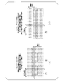
- FIG. 16 is a diagram showing the station placement design technique described in Non-Patent Document 1.
- Non-Patent Document 1 designs a station to eliminate a dead area by using as few base stations as possible.
- the grouping technique of (a) terminal stations shown in FIG. 16 occupies an important part, and suppresses the transmission power of the base station. The amount of interference to the group can be reduced.
- FIG. 17 is a diagram showing a design technique for base station arrangement described in Non-Patent Document 2.
- the allocation rate of users is correctly calculated in consideration of coordinated transmission between base stations.
- FIG. 17A when the macro base station and the small base station independently calculate the user allocation, the small base station is intended to cover the increased number of users in the cell of the macro base station. Even with the additional installation, interference occurs in the area where the cells overlap between the macro base station and the small base station, and the quality deteriorates.
- the base station arrangement using the design technique shown in FIG. 17(b) is compatible with coordinated transmission between base stations, by installing a small base station so that the macro base station and the cell overlap, The quality of the area where a lot of people gather will be improved.
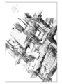
- FIG. 18 is a diagram showing a state in which point cloud data modeling a house shape is displayed in Revit (registered trademark) (Non-Patent Document 3).
- Revit® is a three-dimensional CAD software application for building design. Point cloud data obtained from an actual house as shown in FIG. 18 is processed to model the shape of the house.
- Non-Patent Document 4 point cloud data acquired by MMS (Mobile Mapping System) is used for road surfaces in urban areas and surrounding objects that cannot be accurately acquired by measurement results from aerial photographs.
- the aerial photograph mesh is subjected to fitting processing to embed the point cloud mesh converted from the MMS point cloud data to build high quality measurement data.
- the base station is fixedly installed in an outdoor communication facility such as a telephone pole and the terminal station that wirelessly communicates with the base station is fixedly installed in each building, the actual conditions (environment and surrounding conditions) of the urban area and residential area are taken into consideration. Therefore, it is difficult to properly select and present a strong candidate for installing a base station from a plurality of outdoor communication facilities.
- the amount of data for aerial photogrammetry and MMS point cloud data which deals with environmental conditions such as urban areas and residential areas, is enormous, and if these data are treated as they are in addition to the calculation conditions of the base station station design, This is because it will be difficult to apply because the cost of required calculation resources and calculation time will increase enormously.
- the present invention provides an installation candidate presentation method capable of presenting a candidate position for installing a base station when a base station fixedly installed outdoors wirelessly communicates with a terminal station fixedly installed in a building.
- An installation candidate presentation device and a program are provided.
- One aspect of the present invention is a building in which one or more installation candidates that are candidates for the installation location of the first wireless device and one or more second wireless devices that wirelessly communicate with the first wireless device are installed.
- plan map data showing the plan map of the area including and, for each of the installation candidates, a line-of-sight extraction process of extracting the range of the outline of the building with a line-of-sight from the installation candidates, and measuring the area.
- the area in front of the installation candidate on the wall surface corresponding to the range of the contour extracted by the line-of-sight extraction process is determined.
- One aspect of the present invention is the installation candidate presentation method described above, wherein, in the calculation process, the range of the contour extracted by the line-of-sight extraction process using the three-dimensional map data for each installation candidate. Calculate the number of windows or balconies on the wall surface corresponding to, in the total calculation process, for each of the installation candidates, the number of windows or balconies calculated in the calculation process for the buildings included in the area Calculate the total number.
- One aspect of the present invention is the installation candidate presentation method described above, wherein the installation candidate is an outdoor communication facility in the area, or the communication facility and the first wireless device are attached to the communication facility. And a position separated from the communication equipment by a length corresponding to an instrument sometimes used.
- One aspect of the present invention is a building in which one or more installation candidates that are candidates for the installation location of the first wireless device and one or more second wireless devices that wirelessly communicate with the first wireless device are installed. And a storage unit for storing three-dimensional map data showing a three-dimensional map obtained by measuring the area, and a plane map data showing a plane map of an area including The line-of-sight map data is used to extract the range of the outline of the building with a line-of-sight from the installation candidates, and the line-of-sight extraction unit uses the three-dimensional map data for each of the installation candidates.
- the installation candidate presenting apparatus includes: a total calculating unit for calculating; and a presenting unit for presenting installation candidates selected from the installation candidates based on the total calculated by the total calculating unit.
- One aspect of the present invention is a program for causing a computer to function as the installation candidate presentation device described above.
- a base station fixedly installed outdoors communicates wirelessly with a terminal station fixedly installed in a building, it is possible to present a candidate position for installing the base station.
- the present embodiment relates to a design of a wireless communication system in which a first wireless device installed outdoors and one or more second wireless devices installed in a building wirelessly communicate with each other.
- a case where the first wireless device is a base station and the second wireless device is a terminal station will be described.
- the base station installation candidate presenting apparatus of the present embodiment uses the information of the building handled in the flat map used for communication work, and when the base station is fixed to the communication equipment such as a telephone pole, a plurality of fixed locations are displayed. A range with a line of sight to the contour of the building (hereinafter, also referred to as “plan view wall surface range”) is extracted. Next, the base station installation candidate presentation device uses the separately acquired point cloud data, and with respect to the plan view wall surface range extracted using the plan map, the range of the wall surface of the building that is three-dimensionally viewed from the base station. (Hereinafter, also referred to as “three-dimensional line-of-sight wall range”) is detected, and the area of the detected three-dimensional line-of-sight wall range is obtained.
- the base station installation candidate presentation device similarly obtains the area of the three-dimensional wall surface range from the base station when the base station is installed in another communication facility such as a telephone pole.
- the base station installation candidate presentation device compares the areas of the three-dimensional line-of-sight wall surfaces obtained for each of the candidate communication equipments for installing the base station, and selects the communication equipment having the largest area.
- the base station installation candidate presentation device presents the position of the selected communication facility as the final result of the candidates for installing the base station.
- the base station installation candidate presentation device of this embodiment selects and presents a final candidate for installing a base station by the following solutions 1 to 3.
- the base station installation candidate presentation device uses the point cloud data to calculate the area of the three-dimensional line-of-sight wall surface range, which is the range of the wall surface that can be seen from the base station installation candidate, and calculates all the target buildings in the target area. The total area of the three-dimensional line-of-sight wall area is calculated, and the total, that is, the total area is recorded. (Processing procedure 3) The base station installation candidate presentation device performs the processing procedure 1 and the processing procedure 2 for all base station installation candidates such as another outdoor communication facility in which the base station can be installed.
- the base station installation candidate presentation device compares the total areas of the three-dimensional line-of-sight wall surfaces, and the base station installation candidate with the largest area is obtained. To present.
- the base station installation candidate presentation device presents which of the plurality of outdoor communication facilities is the finally selected base station installation candidate.
- the base station installation candidate is not limited to the position of the outdoor communication equipment, and may be the position where an extension device attached to the outdoor communication equipment is attached. Therefore, the processing procedure 3′ is added to the processing procedure 3 of the base station installation candidate presentation method shown in Solution 1 as follows. That is, the base station installation candidate presentation device expands/diversifies the base station installation candidate from the position of the outdoor communication facility, and performs the processing procedure 1 and the processing procedure 2 for the expanded/diversified base station installation candidate ( Processing procedure 3').
- the base station installation candidate presentation device selects a base station installation candidate to be presented based on the total area of the three-dimensional line-of-sight wall range.
- the base station installation candidate to be presented is selected based on the total number of windows and balconies in the three-dimensional line-of-sight wall range. Therefore, the base station installation candidate presentation device performs the following processing procedure 2′ and processing procedure 2′′ in place of the processing procedure 2 of solution 1 and solution 2. That is, the base station installation candidate presentation device is a point cloud.
- the 3D line-of-sight wall range is detected from the base station installation candidate (processing procedure 2′), and the windows and balconies on the wall including the 3D line-of-sight wall range are detected, and these are detected from the base station installation candidate. Detecting the outlook to the windows and balconies (processing procedure 2"). Further, the base station installation candidate presentation device performs a processing procedure 4′ instead of the processing procedure 4. That is, the base station installation candidate presentation device compares the total number of windows and balconies with prospects calculated for each base station installation candidate, selects the base station installation candidate with the maximum number, and presents it (processing procedure 4′. ).
- FIG. 1 is a functional block diagram showing the configuration of the base station installation candidate presentation device 10.
- the base station installation candidate presentation device 10 is realized by, for example, one or more computer devices.
- the base station installation candidate presentation device 10 includes a candidate selection unit 101, a position acquisition unit 102, a line-of-sight extraction unit 103, a first line-of-sight determination unit 104, an area calculation unit 105, a second line-of-sight determination unit 106, a total area calculation unit 107, and a record.
- the unit 108, the selection unit 109, the presentation unit 110, and the storage unit 121 are provided.
- the storage unit 121 stores map data.
- the map data is, for example, data of a planar (two-dimensional) map of GeoSpace used for Optos (Outside plant Provisioning and in Telligent Operating Systems). Optos is an existing tool for managing outdoor communication equipment, and GeoSpace is an existing map information system.
- the map data includes information on division boundaries, site boundaries, and building contours of each building. Further, additional information such as communication facility information and building information is added to the map data.
- the communication equipment information includes identification information of the communication equipment and information of the position of the communication equipment.
- the communication facility is, for example, a telephone pole.
- the building information includes information such as the name, address and telephone number of the owner or resident of each building.
- the storage unit 121 further stores the point cloud data acquired by the MMS.
- the point cloud data is used as three-dimensional map data. In the following, when simply described as map data, plane (two-dimensional) map data is shown.
- the candidate selection unit 101 refers to the map data and the additional information and selects the communication equipment in the area under consideration as a base station installation candidate.
- the position acquisition unit 102 acquires information on the position of the base station installation candidate selected by the candidate selection unit 101 from the additional information.
- the line-of-sight extraction unit 103 extracts the plane line-of-sight wall range of the considered building from the base station installation candidates using the map data.
- the first prospect judging unit 104 judges whether or not the prospect can be ensured for all the buildings under consideration on the map data (whether there is a plane prospect wall surface range), and when it is judged that the prospect cannot be ensured, the candidate selecting unit Instruct 101 to select a new base station installation candidate.
- the area calculation unit 105 uses the point cloud data to determine the area of the three-dimensional wall surface range from the installation candidate position for each of the plurality of wall surfaces of the target building.
- the second line-of-sight determining unit 106 determines whether or not all the buildings under consideration have a solid line-of-sight wall range. When the second view determining unit 106 determines that all the target buildings have a three-dimensional view wall surface range, the second view determining unit 106 instructs the total area calculation unit 107 to perform the process. When the second line-of-sight determination unit 106 determines that there is a building under consideration that does not have a three-dimensional line-of-sight wall range, it instructs the candidate selection unit 101 to select a new base station installation candidate.
- the total area calculation unit 107 calculates the total area by adding the areas of the three-dimensional perspective wall surface range for all the examination target buildings in the examination target area.
- the recording unit 108 records the total area calculated by the total area calculation unit 107, the identification information of the base station installation candidate, and the installation candidate position in the storage unit 121 in association with each other.
- the selecting unit 109 refers to the total area of the wall surface stored in the storage unit 121, and selects a base station installation candidate that has the maximum total area in the area under consideration.
- the presentation unit 110 presents information on the base station installation candidates selected by the selection unit 109.
- the presentation is, for example, a display on a display.
- the presentation may be printing using a printer, recording on a computer-readable/writable recording medium, or transmission to a computer device connected to the base station installation candidate presentation device 10 via a network.
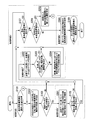
- FIG. 2 is a diagram showing an operation flow of the base station installation candidate presentation processing by the base station installation candidate presentation device 10.
- the operation flow of FIG. 2 shows a specific processing flow of presenting a strong base station installation candidate using the map data and the point cloud data.
- the base station installation candidate presenting apparatus 10 when a base station is installed on an outdoor communication facility (for example, a utility pole) on a planar map, the outline of the target building to be seen through the base station (for example, , Wall), which is the range of the plane perspective wall surface.
- the base station installation candidate presentation device 10 uses the point cloud data to calculate the area of the three-dimensional line-of-sight wall surface range, which is the range of the wall surface that can be seen from the base station for each of the buildings under consideration, and the sum of these areas is calculated. Is recorded in the storage unit 121.
- the base station installation candidate presentation device 10 controls to perform the processing procedure 1 and the processing procedure 2 for all the base station installation candidates such as another power pole on which the base station can be installed.
- the base station installation candidate presentation device 10 compares the total wall surface areas calculated for each base station installation candidate and presents the base station installation candidate having the largest area.
- the examination target area and the examination target building are input to the base station installation candidate presentation device 10 by an input unit (not shown) or registered in the storage unit 121 in advance.
- the base station installation candidate presentation device 10 performs the processing of steps S101 to S103 described below.
- the candidate selecting unit 101 selects any one communication facility in the examination target area as an initial value, and the base station to be processed. It is set as an installation candidate (step S101). It is assumed that there are multiple base station installation candidates in the target area.
- the position acquisition unit 102 acquires information on the position of the selected base station installation candidate from the additional information of the map data stored in the storage unit 121 and sets it as the installation candidate position.
- the candidate selection unit 101 returns to the process of step S101 again after the operation flow of FIG. 2 is started, the candidate base station installation candidate different from the previously selected base station installation candidate is processed. Then, the position acquisition unit 102 sets the position of the processing target base station installation candidate as the installation candidate position.
- the line-of-sight extraction unit 103 simply uses the map data of the plane map to easily extract the line-of-sight from the base station installation candidate to the building contour (step S102).
- the line-of-sight extraction unit 103 draws a straight line that connects the installation candidate position acquired by the position acquisition unit 102 in step S101 described above and the building contour of the study target building included in the study target area on the two-dimensional map. If the drawn straight line does not overlap other building contours, the building contour can be regarded as having visibility.
- the line-of-sight extraction unit 103 performs this confirmation process for all the building contours of all the examination target buildings within the examination target area, and extracts the plane-view wall surface range that is the building contour with the sight.
- the first prospect judging unit 104 judges whether or not the prospect can be secured for all the buildings under consideration on the map data (step S103). As a result of extracting the plane view wall surface range by the building contour in the process of step S102, even a part of the contour of one or more study buildings in the study area from the candidate installation location It may be confirmed that there is no. Therefore, in the determination processing of step S103, the first line-of-sight determining unit 104 determines whether all of the buildings under consideration in the area under consideration have a perspective from the base station installation candidate in the building contour (plan view wall surface range is Yes) or not.
- step S103 When determining that all the target buildings are in view (step S103: YES), the first line-of-sight determining unit 104 hands over the process to the area calculating unit 105, and proceeds to step S104 of the next processing procedure 2.
- step S103: NO When the first view determining unit 104 determines that there are some of the buildings under consideration that do not have a view (step S103: NO), the process is passed to the candidate selecting unit 101, and the process proceeds to step S107 of process procedure 3 described later. The operation of the processing procedure 1 described above will be described later with reference to FIG.
- the base station installation candidate presentation device 10 performs the processes of steps S104 to S106.
- the area calculation unit 105 uses the point cloud data to obtain a prospective area from each installation candidate position for each wall surface of each target building (step S104).
- the area calculation unit 105 uses the point cloud data acquired by the MMS that actually travels in the study area instead of the plane (two-dimensional) map, and examines the study area from the base station installation candidates.
- the area calculation unit 105 performs this confirmation for each of all the target buildings in the target area and for each of the plurality of wall surfaces of the target building, and each wall has a prospect.
- the area of the three-dimensional line-of-sight wall range which is the range, is calculated.
- the second line-of-sight determining unit 106 determines whether or not there is a line-of-sight on the walls of all the examination target buildings (step S105). As described above, after the building contour (corresponding to the wall) is considered to have a line of sight in the processing procedure 1, in step S105, the area to be examined is determined using the result of the line-of-sight confirmation using the point cloud data. Determine whether all the buildings under consideration have a three-dimensional perspective. The reason for determining the perspective based on the point cloud data is that, even if there is a perspective on a two-dimensional map, in reality, there are fences at the boundary of the site and roadside trees.
- step S105 determines NO in step S105, transfers the process to the candidate selection unit 101, and proceeds to step S107 of processing procedure 3 described later. move on.
- the second perspective determining unit 106 determines YES in step S105 and transfers the processing to the area calculating unit 105. To step S106.
- the recording unit 108 records the area of the three-dimensional line-of-sight wall range of the study target building whose line-of-sight confirmation has been completed by the area calculation unit 105 (step S106). Therefore, the total area calculation unit 107 determines the area of the three-dimensional line-of-sight wall range obtained by the area calculation unit 105 in step S104 as described above for all the target buildings in the study area If so, the total area is calculated by adding up for these multiple three-dimensional line-of-sight wall ranges.
- the recording unit 108 records the calculated total area in the storage unit 121. When the recording unit 108 performs this recording, the identification information of the base station installation candidate and the installation candidate position that have become the reference of visibility are stored in the storage unit 121 in association with each other.
- the base station installation candidate presenting apparatus 10 reads and uses the recorded information when comparing all the base station installation candidates in the subsequent processing procedure 4. Note that the details of the operation meant by the processing procedure 2 described above will be described later with reference to FIGS. 4 and 6.
- the base station installation candidate presenting apparatus 10 performs the following step S107. That is, the candidate selection unit 101 determines whether there are any remaining base station installation candidates (step S107). In this step S107, when it is determined in the processing procedure 1 that there is a study target building in which the view cannot be secured in the study target area by the map data (step S103: NO), the point cloud data is used to view the study target area in the processing procedure 2. When it is determined that there is an examination target building that does not have any (step S105: NO), and when the processing for recording the total area of the three-dimensional perspective wall surface range of all the examination target buildings in the examination target area in processing procedure 2 is completed ( This is executed in step S106).
- the candidate selection unit 101 causes the candidate base station installation candidates other than the base station installation candidates that have been selected so far, and the remaining base station installation candidates (communication equipment different from the communication equipment that has been selected as the study object so far) ) Is still present to make a judgment.
- the candidate selection unit 101 determines that there is another base station installation candidate (step S107: YES)
- the candidate selection unit 101 returns to step S101 of the processing procedure 1 again, and a base station different from the already selected base station installation candidate.
- the installation candidate is selected, and the base station installation candidate presentation device 10 repeats the subsequent processing in order.
- the candidate selection unit 101 determines that there is no other base station installation candidate (step S107: NO) it transfers the process to the selection unit 109 and proceeds to step S108.
- the base station installation candidate presentation device 10 performs the following steps S108 and S109.
- the selecting unit 109 selects a base station installation candidate that has the largest total area out of the total areas of the wall surfaces (three-dimensional wall surface range) recorded in the storage unit 121 (step S108). That is, the selection unit 109 compares all the total areas of the three-dimensional line-of-sight wall surface range for each base station installation candidate recorded in step S106 of the above processing procedure 2. Based on the result of this comparison, the selection unit 109 selects the base with the largest total area of the wall surface with prospect from all the base station installation candidates for which all the target buildings in the target area have been confirmed to be in perspective. Select a station installation candidate.
- the presenting unit 110 displays the results of the base station installation candidates selected by the above processing (step S109). That is, the presentation unit 110 presents the information of the base station installation candidate selected by the selection unit 109 in the immediately preceding step S108 to the user through the above processing. For example, the presentation unit 110 displays information such as the name and identification information of the base station installation candidate selected by the selection unit 109 and the position on the map on the display. The details of the operation that the processing procedure 4 means will be described later with reference to FIG. 7.
- the selection unit 109 may assign ranks in descending order of total area and select base station installation candidates with a predetermined rank or higher, or select all base station installation candidates for which the total area has been calculated. May be.
- the presentation unit 110 displays, on the display, information on the ranking and total area in addition to the information such as the name and identification information of the base station installation candidate selected by the selection unit 109 and the position on the map. To do. Further, the presentation unit 110 may display the information of the base station installation candidate determined to be NO in step S103 or step S105 and the fact that there is no prospect.
- step S103 when the base station installation candidate presenting apparatus 10 determines in step S103 that there is a prospect in a part of the examination target area or a predetermined proportion or more of the examination target buildings, as in the case of determining YES in the above, You may make it perform the process of step S104. Further, when the base station installation candidate presenting apparatus 10 determines that there is a prospect in a part of the processing target area or a predetermined proportion or more of the target buildings in Step S105, as in the case of determining YES in the above, You may make it perform the process of step S106. In this case, the presentation unit 110 could secure the view only in some of the buildings under consideration, the proportion of the buildings under consideration in the area under consideration, and the perspective. Information on the building under consideration that could not be obtained may be presented.
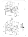
- FIG. 3 is a diagram showing an operation of processing procedure 1 of the base station installation candidate presentation device 10.
- the outline (wall) of the building that can be seen from the base station installation candidate (electric pole) is extracted based on the map data.
- FIG. 3A is an example of map data, and is an excerpt of a portion of the residential area selected as the examination target area.
- FIG. 3B is a view showing a contour (wall) of a building in a residential area with respect to a building in a residential area by utilizing information added to the map data (plan view wall surface range). The following shows how to extract.
- the division boundary is indicated by the thick solid line L1, and the road in the residential area under consideration can be confirmed.
- a site boundary is indicated by a broken line L2
- (a contour of, a wall surface of) the examination target building is indicated by a solid line L3.
- the building (the contour and the wall surface) to be excluded from the examination target after this is shown by a broken line L4.
- the reference signs D1 to D4 on the roads and section boundaries indicate utility poles.
- a utility pole is one of the outdoor communication facilities.
- the line-of-sight extraction unit 103 assumes that one base station, which is one of the wireless stations that communicate with each other, is installed on a telephone pole, and that the other wireless station, the terminal station, is installed in a plurality of buildings in the housing area under consideration.
- the map data shown in FIG. 3 is used to obtain the plane line-of-sight wall range that is the contour (wall) of the building under consideration from each of the utility poles D1 to D4. This process corresponds to the process of step S102 of FIG. 2 described above.
- a thick dashed line L 5 indicates a plane view wall surface range from the electric pole D 1 among the four electric poles D 1 to D 4.
- the line-of-sight extraction unit 103 may determine that a place with a narrow space between buildings is out of line-of-sight from the utility pole and exclude it from the line-of-sight confirmation target.
- a certain threshold value is set for a place where the space between buildings is small. For example, when the threshold value is 40 cm, when the distance between buildings is 40 cm or less, only the range of the wall surface from 1 m to 2 m from the road side is treated as the plane view wall surface range even if there is a view.
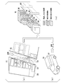
- FIG. 4 is a diagram showing an operation of processing procedure 2 of the base station installation candidate presentation device 10.
- the area calculation unit 105 matches the point cloud data with the map data shown in FIG.
- FIG. 4A shows information on the plane line-of-sight wall surface range L5 from the electric pole D1 extracted as shown in FIG. 3B described above.
- FIG. 4B shows a vehicle 32 equipped with the MMS 31.
- the vehicle 32 acquires point cloud data by the MMS 31 while traveling on a road around the residential area under consideration.
- the road on which the vehicle 32 equipped with the MMS 31 has traveled is indicated by an arrow in FIG.
- the area calculation unit 105 uses the point cloud data acquired by the MMS 31 in addition to the above-described information of the plane-view wall surface range L5.
- FIG.4(c) shows the solid line-of-sight wall range W1 which is the wall surface of the building under consideration which can be seen from the telephone pole D1 and which was calculated
- FIG. 4C shows the operation of the processing procedure 2 described in FIG. 2, in which the area calculation unit 105 matches the point cloud data with the map data, and from the telephone pole D1 of the building under consideration in the three-dimensional space.
- the three-dimensional perspective wall surface range W1 of That is, by using the position (latitude/longitude) of the plane-view wall surface range L5 from the telephone pole D1 obtained in the map data, it is possible to narrow down the wall information of the building in the point cloud data acquired for the residential area under consideration. Further, since the positions of the electric poles D1 to D4 can be similarly confirmed from the map data, the electric pole information in the point cloud data can be narrowed down.
- the area calculation unit 105 determines both the point cloud data corresponding to the plane-view wall surface range L5 on the map and the point cloud data corresponding to the telephone pole on the map, and other three-dimensional points around them. Using the group data, it is possible to confirm how much visibility is actually on the wall surface of the considered building from the utility pole. Even if there is a line of sight on the map, there may be a fence fence at the boundary of the site, or the branches and leaves of the roadside trees may obstruct the area of the wall that has a line of sight with the utility pole. The area calculation unit 105 can carry out such an actual line-of-sight confirmation with the shield using the three-dimensional point cloud data.
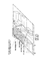
- FIG. 5 is a diagram showing narrowing down of the point cloud data acquired by the MMS 31.
- the area calculation unit 105 utilizes part of the point cloud data narrowed down as shown in FIG. 5 for the process of line-of-sight confirmation.
- the range A1 is a range of the point cloud data acquired by the MMS 31 when the vehicle 32 travels on the road on the map shown in FIG.
- the data capacity of the point cloud data acquired by the MMS 31 is enormous. Therefore, as shown in FIG.
- all the point cloud data in the range A1 is used when performing the processing procedure 2 for confirming the three-dimensional line-of-sight wall surface range W1 in each target building from the telephone pole based on the point cloud data. This is not practical in terms of cost such as calculation resources and calculation time.
- the area calculation unit 105 narrows down the processing target to the range A2 that includes the building under consideration within the range of the residential area under consideration and the telephone pole that is the candidate for base station installation, and the point cloud data of the narrowed range A2. Use to confirm whether there is a line of sight.
- the area calculation unit 105 also utilizes the map data and the additional information to narrow down the range of the point cloud data, obtains the positions (latitude/longitude) of each of the target building and the utility pole from the map data and the additional information, and calculates these latitudes. -Limit the point cloud data to the range A2 based on the longitude. Also, each point in the point cloud data has no size.
- the area calculation unit 105 regards each point of the point cloud data as a sphere having a diameter of about 10 cm. The area calculation unit 105 determines whether or not the sphere-shaped point cloud intercepts the straight line M connecting the utility pole and the wall surface of the building under consideration to determine whether or not there is a line of sight.
- FIG. 6 is a diagram showing the operation of processing procedure 2 (x) in the base station installation candidate presentation device 10.
- Process procedure 2 (x) is a process procedure 2 to be performed for the installation candidate position of the x-th base station installation candidate.
- Processing procedure 2 shown in FIG. 4 corresponds to processing procedure 2 (1) .
- the area calculation unit 105 determines the area of the three-dimensional wall surface range of the building under consideration from the installation candidate position different from that in FIG. Ask.
- FIG. 6A shows information of the plane line-of-sight wall range L6, which is the contour (wall) of the building with the line of sight from the telephone pole D2, acquired in the same manner as in FIG.
- FIG. 6B shows a vehicle 32 equipped with the MMS 31, which is driven on a road corresponding to the vicinity of the same residential area as in FIG.
- the area calculation unit 105 uses the point cloud data acquired by the MMS 31 in addition to the information of the plane-view wall surface range L6 of the building under consideration with consideration.
- FIG. 6C shows the result of the area calculation unit 105 using the point cloud data to obtain the three-dimensional line-of-sight wall area W2 that is the wall surface of the building under consideration that can be seen from the telephone pole D2.
- FIG. 6 shows an operation similar to or similar to the processing procedure 2 shown in FIG. The difference is that a utility pole different from that in FIG. 4 is used as a candidate for the installation position of the base station.
- a utility pole different from that in FIG. 4 is used as a candidate for the installation position of the base station.
- FIG. 6(a) of the four utility poles D1 to D4 on the map, another utility pole D2 different from the utility pole D1 used in FIG. 4 is selected, and in FIG. 6(c), From the utility pole D2, it is confirmed to what extent the wall surface of the building under consideration has visibility.
- processing procedure 2 corresponding to processing procedure 2 (1)
- processing procedure 2 processing procedure 2 (processing procedure 2 (x) ) shown in FIG.
- the processing procedure 2 is performed only for the base station installation candidates whose visibility can be secured on the map.
- the area calculation unit 105 performs processing procedure 2 (1) ,..., Processing procedure 2 (x) ,. Perform Step 2 (n) to determine whether there is visibility on the wall surface of the building under consideration and determine the area of the three-dimensional wall surface area.
- FIG. 7 is a diagram showing the operation of processing procedure 4 in the base station installation candidate presentation device 10.
- the selection unit 109 compares the total areas of the three-dimensional line-of-sight wall surfaces obtained for each of the plurality of base station installation candidates.
- a case will be described as an example in which there are two base station installation candidates that have visibility on the wall surfaces of all the buildings under consideration, namely, utility poles D1 and D2.
- FIG. 7A shows the three-dimensional wall surface range W1 of the building under consideration from the telephone pole D1 obtained by the area calculation unit 105 in FIG.
- FIG. 7B shows the three-dimensional wall surface range W2 of the building under consideration from another utility pole D2, which is obtained by the area calculation unit 105 in FIG.
- FIG. 7C is a diagram showing a comparison of the total areas of the three-dimensional line-of-sight wall surfaces W1 and W2.
- FIG. 7A is a bird's-eye view of a building (target of installing a wireless terminal station) and a utility pole (candidate of installing a base station) in a residential area under consideration based on the point cloud data.
- FIG. 7A shows a wall surface of a building under consideration that has a prospect from the utility pole D1 by utilizing the point cloud data among the two utility poles D1 and D2 standing on the road. The confirmed result (FIG.4(c)) is shown.
- the three-dimensional line-of-sight wall surface range W1 is a portion that is in line of sight from the telephone pole D1.
- FIG. 7(b) shows a bird's eye view of the buildings and telephone poles in the residential area under consideration based on the point cloud data.
- the electric pole D2 is a target for consideration, and the wall surface of the target building that is prospective from the electric pole D2 is utilized by utilizing the point cloud data.
- the confirmed result (FIG.6(c)) is shown.
- the three-dimensional line-of-sight wall surface range W2 is a part that is in line of sight from the telephone pole D2.
- Reference symbol B1 in FIG. 7C indicates only the three-dimensional perspective wall surface range W1 of the study target building that is visible from the above-described utility pole D1
- reference symbol B2 is the three-dimensional perspective wall surface range of the study target building that is prospective from the above-described utility pole D2. Only W2 is extracted. It should be noted that one building to be examined may have a plurality of wall surfaces including the three-dimensional line-of-sight wall range. Further, as shown in FIG. 7C, since the three-dimensional line-of-sight wall range is for a plurality of buildings, the total area calculation unit 107 determines the area of the three-dimensional line-of-sight wall range of the plurality of buildings within the housing area under consideration. Sum up.
- the selection unit 109 compares the total area of the three-dimensional line-of-sight wall surface range W1 from the telephone pole D1 with the total area of the three-dimensional line-of-sight wall surface range W2 from the telephone pole D2. In the example of FIG. 7C, the total area calculated for the telephone pole D2 is larger.
- the base station installation candidate presentation device 10 similarly obtains the total area of the three-dimensional wall surface range of the building under consideration for another electric pole in the same manner, and the selection unit 109 compares the totals. That is, the base station installation candidate presentation device 10 determines whether there is a prospect on the wall surface of the building under consideration from the positions (installation candidate positions) of all the utility poles in the residential area to be considered, and when which utility pole is selected Compare if the total of the three-dimensional line-of-sight wall area is large. Then, the presentation unit 110 compares all the electric poles and determines the electric pole having the largest total area as the base station installation candidate to be presented (process procedure 4 shown in FIG. 2).
- Solution 2 presents a base station installation candidate.
- the communication equipment is the base station installation candidate.
- the base station installation candidates are diversified by setting the base station installation candidates also around the communication equipment. Below, it demonstrates centering around the difference with 1st Embodiment.
- FIG. 8 is a functional block diagram showing the configuration of the base station installation candidate presentation device 11. 8, the same parts as those of the base station installation candidate presenting apparatus 10 according to the first exemplary embodiment shown in FIG. 1 are designated by the same reference numerals, and the description thereof will be omitted.
- the base station installation candidate presentation device 11 shown in the figure is different from the base station installation candidate presentation device 10 of the first embodiment in that the candidate selection unit 101 and the position acquisition unit 102 are replaced by a candidate selection unit 131 and a position. This is a point including the acquisition unit 132.
- the candidate selection unit 131 selects a diversified base station installation candidate.
- the position acquisition unit 132 acquires the position of each base station installation candidate including the diversified base station installation candidates.
- FIG. 9 is a diagram showing an operation flow of base station installation candidate presentation processing by the base station installation candidate presentation device 11.
- the same processes as those in the operation flow of the first embodiment shown in FIG. 2 are designated by the reference numerals in the figure, and detailed description thereof will be omitted.
- the operation flow of the base station installation candidate presenting apparatus 11 of the present embodiment illustrated in FIG. 9 also includes four processing procedures (processes). That is, in the first processing procedure 1, the base station installation candidate presentation device 11 has a plane view wall surface that is the range of the contour (wall) of the building that is visible from the base station installed on the outdoor facility (electric pole) on the map. Extract the range.
- the base station installation candidate presentation device 11 calculates the area of the three-dimensional line-of-sight wall surface range, which is the range of the wall surface that can be seen from the base station for each building under consideration, using the point cloud data, and the sum of these areas is calculated. Is recorded in the storage unit 121.
- the base station installation candidate presentation device 11 performs a processing procedure 3'instead of the processing procedure 3 of FIG.
- the base station installation candidate presenting apparatus 10 of the first exemplary embodiment processes the processing procedure 1 and the processing procedure with respect to all the base station installation candidates such as another utility pole in which the base station can be installed. I was controlling to do 2.
- the base station installation candidate presenting device 11 sets the base station installation candidate to the outdoor communication equipment not limited to the outdoor communication equipment (such as a utility pole) targeted for management on the map. Expand and diversify the base station by installing attached expansion equipment.
- the operation flow of FIG. 9 includes the processing of the processing procedure 3'considering the diversified installation candidate positions.
- the base station installation candidate presenting apparatus 11 compares the total wall surface areas calculated for the respective base station installation candidates, and presents the base station installation candidate having the largest total area. In the following, each of these four processing procedures will be described one by one.
- the candidate selecting unit 131 selects any one of the communication equipments in the examination target area, and the position acquiring unit 132 acquires the information on the position of the selected base station installation candidate from the map data. It is acquired from the additional information (step S101).
- the line-of-sight extraction unit 103 uses the map data of the two-dimensional map to easily extract the line of sight from the base station installation candidate to the building contour (step S102).
- the first line-of-sight determining unit 104 determines whether or not the line-of-sight can be secured for all the buildings under consideration on the map data (step S103).
- step S103 determines that the visibility can be ensured for all the examination target buildings
- step S103: NO the first line-of-sight determining unit 104 determines that there are some of the target buildings for which the line-of-sight cannot be secured
- step S103: NO the process is passed to the candidate selecting unit 131, and step S107 of the processing procedure 3′. Go to.
- the area calculation unit 105 uses the point cloud data to obtain a prospective area from each installation candidate position for each wall surface of each target building (step S104).
- the second line-of-sight determining unit 106 determines whether or not the walls of all the buildings under consideration have a line-of-sight (step S105).
- the candidate selection unit 101 performs the process of step S107 of the process procedure 3'.
- the total area calculation unit 107 determines the area of the three-dimensional view wall surface range for all the examination objects buildings within the examination target area. Calculate the total area added.
- the recording unit 108 records the calculated total area in the storage unit 121 in association with the identification information of the base station installation candidate and the installation candidate position (step S106).
- the processing procedure 1 and the processing procedure 2 so far shown in FIG. 9 are the same as those in the first embodiment shown in FIG.
- the base station installation candidate presentation device 11 performs the processes of the following steps S107 and S201 to S202.
- the candidate selection unit 131 determines whether there are any remaining base station installation candidates (step S107).
- step S107 when it is determined in the processing procedure 1 that there is a study target building in which the view cannot be secured in the study target area by the map data (step S103: NO), the point cloud data is used to view the study target area in the processing procedure 2.
- step S105: NO when it is determined that there is an examination target building that does not have any (step S105: NO), and when the processing for recording the total area of the three-dimensional perspective wall surface range of all the examination target buildings in the examination target area in processing procedure 2 is completed ( This is executed in step S106).
- the candidate selection unit 131 confirms and determines whether or not there are still other base station installation candidates in the area under consideration other than the base station installation candidates selected so far (step S107). ..
- the candidate selection unit 131 determines that there is another base station installation candidate (step S107: YES)
- the candidate selection unit 131 returns to step S101 of the processing procedure 1 again, and a base station different from the already selected base station installation candidate.
- the installation candidate is selected, and the base station installation candidate presentation device 11 repeats the subsequent processing in order.
- the candidate selecting unit 131 determines that there is no other base station installation candidate (step S107: NO)
- the process proceeds to step S201.
- the candidate selection unit 131 determines whether there are diversified base station installation candidates (step S201).
- the outdoor communication facility such as a power pole to be managed in the map data
- the present embodiment is not limited to such outdoor communication equipment.
- a traffic signal is attached to a utility pole (post) so that it can be easily seen from a moving vehicle entering the intersection.
- the base station installation candidates will be expanded and diversified within a few meters around the utility pole by installing expansion equipment.
- the candidate selection unit 131 confirms whether there are any remaining base station installation candidates including the diversified base station installation candidates.
- the diversified distance from the utility pole of the base station installation candidate may be the distance stored in the storage unit 121 in advance, and information on the type of base station to be installed stored in the storage unit 121 in advance or The distance may be set according to the type of expansion device used.
- the direction from the diversified base station installation candidate utility pole is 0 degree in a predetermined direction (for example, the east direction, the direction parallel to the road, etc.), and the range from 0 degree to 360 degrees is incremented by a predetermined angle. (For example, 0 degrees, 90 degrees, 180 degrees, and 270 degrees divided by 90 degrees).
- the candidate selection unit 131 performs the process of step S202.
- step S201 if the candidate selection unit 131 has already considered the diversified base station installation candidates and determines that there are no remaining base station installation candidates (step S201: NO), it transfers the processing to the selection unit 109, and the processing procedure. 4 proceeds to step S108.
- the candidate selecting unit 131 selects one position from the diversified base station installation candidates, and the position acquisition unit 132 sets the position of the selected base station installation candidate as the calculation condition (step S202). Since it has been confirmed in the previous step S201 that the diversified base station installation candidates still remain (step S201: YES), the operation of this step S202 is performed. Therefore, in this step S202, the position acquisition unit 132 acquires the position of the base station installation candidate selected from the remaining diversified base station installation candidates, and then the line-of-sight extraction unit 103 again executes step S102 of the processing procedure 1. Perform processing. Details of the diversification of base station installation candidates related to this processing procedure 3'will be described later with reference to FIG.
- the selection unit 109 selects a base station installation candidate that has obtained the maximum total area out of the total areas of the wall surfaces (stereoscopic wall surface range) recorded in the storage unit 121 (step S108). ..
- the presentation unit 110 presents the results of the base station installation candidates selected in step S108 in the same manner as in the first embodiment (step S109).
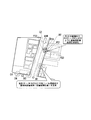
- FIG. 10 shows an example of a mounting form of a base station on a telephone pole.
- 10(a) and 10(b) show different mounting modes of base stations.
- reference numeral 51 is a telephone pole
- reference numeral 52 is an accessory
- reference numeral 53 is a communication cable.
- Reference numeral 54 is a base station, specifically, a WiMAX R2.1 AE base station.
- reference numeral 61 is a telephone pole
- reference numeral 62 is an accessory
- reference numeral 63 is a communication cable.
- Reference numeral 64 is a base station, and more specifically, it is an NTT Docomo optical device (MOF).
- MOF NTT Docomo optical device
- FIGS. 10(a) and 10(b) there may be various forms of attaching a wireless station or the like to a telephone pole.
- a horizontal rod-shaped mounting jig is installed as an accessory for attachment in the middle of the ground and the upper end of the utility pole, and equipment such as a base station is installed at a certain distance from the utility pole. It is a point. It can also be seen that the middle of the utility pole to which the accessory is attached is slightly below the height of the communication cable.
- FIG. 11 is a diagram showing an example of diversification of base station installation candidates.
- FIG. 11 shows a map range (installation candidate positions) that base station installation candidates diversified according to the installation form of base stations on telephone poles can be.
- the utility pole D2 is described within the range of the circle C2, for example, in the north, south, east, and west directions centering on the utility pole D2.
- the circles P21 to P24 are installed horizontally by an accessory for attaching the base station to the telephone pole D2 as shown in FIG. It is conceivable to extend/extend the rod-shaped portion to a desired length.
- the circles P21 to P24 shown on the map can be the position candidates for installing the diversified base stations.
- diversified base station installation candidates can be considered in the operation flow of the base station installation candidate presentation device 11 shown in FIG. As described above, by changing the base station installation candidates (installation candidate positions) within a radius of 1 to 2 m around the telephone pole, it is possible to diversify the base station installation candidates and to easily obtain a perspective of the wall surface of the building. Become.
- the present embodiment presents base station installation candidates by Solution 3.
- the base station installation candidate to be presented is selected based on the total area of the three-dimensional line-of-sight wall area.
- base station installation candidates to be presented are selected based on the number of windows and balconies on the wall in the three-dimensional line-of-sight wall range of the building under consideration.
- the present embodiment may be applied to the case where the terminal station is installed on a window or a veranda. Below, it demonstrates centering around the difference with 1st and 2nd embodiment.
- FIG. 12 is a block diagram showing the configuration of the base station installation candidate presentation device 12 according to the present embodiment. 12, the same parts as those of the base station installation candidate presenting apparatus 11 according to the second exemplary embodiment shown in FIG. 8 are designated by the same reference numerals, and the description thereof will be omitted.
- the base station installation candidate presenting device 12 shown in the figure is different from the base station installation candidate presenting device 11 of the second embodiment in that an area calculation unit 105, a second line-of-sight determination unit 106, a total area calculation unit 107, and a record.
- an area calculation unit 141 a second line-of-sight determination unit 142, a detection unit 143, a third line-of-sight determination unit 144, a total number calculation unit 145, a recording unit 146, and a selection unit 147 are provided. ..
- the area calculation unit 141 obtains the area of the three-dimensional wall surface area with a line of sight from the base station installation candidate for each of the plurality of wall surfaces of the target building by using the point cloud data, and when the area is larger than a predetermined reference, Judge that there is a prospect.
- the second line-of-sight determining unit 142 determines whether or not all the walls of the target building have a line-of-sight.
- the detection unit 143 uses the point cloud data to detect windows and balconies from the wall surface with the prospect of each building under consideration.
- the third line-of-sight determining unit 144 determines whether or not there is a study target building in the study target area that has no prospective window or veranda.
- the total number calculation unit 145 calculates the total number of windows and balconies that are prospective from the base station installation candidates for all the target buildings in the target area.
- the recording unit 146 writes the total number of windows and balconies calculated by the total number calculation unit 145 in the storage unit 121.
- the selection unit 147 selects a base station installation candidate to be presented based on the total number of windows and balconies.
- FIG. 13 is a diagram showing an operation flow of the base station installation candidate presentation processing by the base station installation candidate presentation device 12.
- the same processes as those in the operation flow of the second embodiment shown in FIG. 9 are designated by the reference numerals in the figure, and detailed description thereof will be omitted.
- the first processing procedure 1 when the base station installation candidate presentation device 12 installs the base station on the outdoor communication facility on the map, the base station installation candidate presentation device 12 can see through the base station, as in the first and second embodiments. Extract the contour of the building under consideration.
- the base station installation candidate presentation device 12 performs processing procedure 2′ and processing procedure 2′′ in the operation flow of FIG. 13 instead of the processing procedure 2 of the first and second embodiments.
- the base station installation candidate presenting device 12 detects the windows and balconies from the wall that can be seen from the base station by using the point cloud data, and if all the target buildings have visible windows or balconies, Record the total number of windows and balconies.
- the processing procedure 3′ is similar to that of the second embodiment, and the base station installation candidate presentation device 12 expands/diversifies the base station installation candidates.
- the base station installation candidate presentation device 12 performs a processing procedure 4′ in the operation flow of FIG. 13, instead of the processing procedure 4 of the first and second embodiments.
- the base station installation candidate presentation device 12 compares the total number of windows and balconies with prospects detected for each of the base station installation candidates in the processing procedure 2′′ described above, and selects and presents the maximum number of base station installation candidates.
- the base station installation candidate presenting apparatus 12 of the present exemplary embodiment performs the processing procedure 2′ and the processing procedure 2′′ in place of the processing procedure 2 of FIGS. 2 and 9, and the processing procedures of FIGS.
- the procedure 4' is performed instead of the procedure 4.
- the base station installation candidate presenting apparatus 12 performs the procedure 3'in Fig. 9, but the procedure 3'instead of the procedure 3 in Fig. 2.
- the base station installation candidate presentation device 12 does not look from the base station to the wall surface but detects windows and balconies on the wall surface and looks into these windows and balconies.
- the base station installation candidate presentation device 12 does not compare the total area of the wall surfaces with the line of sight in the processing procedure 4, but compares the total number of windows and balconies with the line of sight.
- each processing will be described in detail in order.
- the candidate selecting unit 131 selects any one of the communication equipments in the examination target area, and the position acquiring unit 132 acquires the information on the position of the selected base station installation candidate from the map data. It is acquired from the additional information (step S101).
- the line-of-sight extraction unit 103 uses the map data of the two-dimensional map to easily extract the line of sight from the base station installation candidate to the building contour (step S102).
- the first line-of-sight determining unit 104 determines whether or not the line-of-sight can be secured for all the buildings under consideration on the map data (step S103).
- step S103 determines that the visibility can be secured for all the buildings under consideration
- step S103: NO the first line-of-sight determining unit 104 determines that there are some of the target buildings for which the line-of-sight cannot be secured
- step S103: NO the process is passed to the candidate selecting unit 131, and step S107 of the processing procedure 3′. Go to.
- the base station installation candidate presentation device 12 performs the following steps S301 and S105.
- the area calculation unit 141 confirms the prospect from the base station installation candidate for each of the plurality of wall surfaces of each target building using the point cloud data (step S301).
- the area calculation unit 141 uses the point cloud data to form the line-of-sight on the wall surface of the building in step S301.
- the confirmation at this time is a preliminary check to see if windows and balconies can be detected on the wall surface in the subsequent processing procedure 2′′. Therefore, a part of the wall surface that is in sight has a certain reference area (at least a small window exists).
- the area calculation unit 141 obtains a prospective area from the base station installation candidate for each of the plurality of wall surfaces of each building under consideration using the point cloud data, and the area is determined to be a predetermined value. If it is larger than the standard, the line of sight is present, and if it does not meet the predetermined standard, it is determined that the line of sight is not present. The result of the confirmation in step S301 is used for the determination of the subsequent step S105.
- the second line-of-sight determining unit 142 determines whether or not there is a line-of-sight on the wall surfaces of all the buildings under consideration (step S105).
- the second line-of-sight determining unit 142 receives the line-of-sight confirmation result of the wall surface of the examination target building in step S301, and determines that all the wall surfaces of the examination target building in the examination target area have the line of sight (step S105: YES)
- the process is passed to the detection unit 143, and the process proceeds to step S302 of the processing procedure 2′′.
- the detection unit 143 detects the windows and balconies on each wall surface. If it is determined that there is also a part of the building under consideration that has no line of sight (step S105: NO), the process is passed to the candidate selection unit 131, and the process proceeds to step S107 of the process procedure 3′.
- the base station installation candidate presentation device 12 performs the following steps S302 to S304.
- the detection unit 143 uses the point cloud data to detect windows and balconies from the respective wall surfaces (step S302).
- step S302 When it is determined in step S105 of the processing procedure 2′ described above that the walls of all the target buildings are in sight (YES), the process of step S302 is performed.
- the detection unit 143 extracts the point cloud data of the plane portion corresponding to each wall surface with the line of sight, by collating the point cloud data with the latitude and longitude of the building contour on the map data.
- the detection unit 143 performs window and veranda detection processing on each piece of point cloud data on one plane that corresponds to the wall surface.
- step S302 of detecting a window or a veranda from the point cloud data of one plane that hits the wall surface will be described later with reference to FIGS. 14 and 15.
- the third visibility determining unit 144 determines whether or not there is a building under consideration without any windows or balconies with visibility (step S303).
- the third line-of-sight determination unit 144 confirms whether or not the windows and balconies of those wall faces have a line-of-sight from base station installation candidates.
- the third outlook determination unit 144 determines YES when there is at least one building under consideration that has no windows or balconies with prospects from the base station installation candidates in the area under consideration, and determines all of the objects under consideration within the area under consideration. If the building has one or more windows or balconies with a view, it is judged as NO.
- step S303 If the third view determination unit 144 determines YES in step S303, it transfers the process to the candidate selection unit 131, and proceeds to step S107 of the processing procedure 3'. When the third view determination unit 144 determines NO in step S303, the process is passed to the total number calculation unit 145, and the process proceeds to step S304.
- the recording unit 146 records, in the storage unit 121, the total number of windows and balconies of all the examination target buildings whose visibility has been confirmed (step S304).
- the process of step S304 is performed when it is confirmed (NO) that there is a window or a balcony with a line-of-sight in all the target buildings in step S303 immediately before. Therefore, the total number calculation unit 145 calculates the total number by adding the number of windows or balconies detected by the detection unit 143 in step S303 described above for all the examination target buildings in the examination target area.
- the recording unit 146 records the calculated total number in association with the identification information of the base station installation candidates and the installation candidate position in the storage unit 121.
- the base station installation candidate presentation device 12 proceeds to step S107 of the processing procedure 3'.
- the candidate selection unit 131 determines whether there are any remaining base station installation candidates (step S107).
- step S107 when it is determined in the processing procedure 1 that there is a study target building whose view cannot be secured in the study target area with the map data (step S103: NO), the point cloud data is used to determine the study target area in the processing procedure 2′.
- step S105: NO when it is determined that there is a study target building that does not have a line of sight (step S105: NO), when it is determined that there is a study target building that does not have a window or a balcony with a view in the study target area in processing procedure 2′′ (step S303).
- step S304 when the process of recording the total number of windows and balconies of all the target buildings in the target area in the procedure 2" is finished (step S304).
- the candidate selection unit 131 confirms and determines whether or not there are still other base station installation candidates in the area under consideration in addition to the base station installation candidates selected so far (step S107). .. If the candidate selection unit 131 determines that there is another base station installation candidate (step S107: YES), the candidate selection unit 131 returns to step S101 of the processing procedure 1 again, and a base station different from the already selected base station installation candidate. The installation candidate is selected, and the base station installation candidate presentation device 12 repeats the subsequent processing in order. On the other hand, when the candidate selection unit 131 determines that there is no other base station installation candidate (step S107: NO), the process proceeds to step S201.
- the candidate selection unit 131 determines whether there are diversified base station installation candidates as in the second embodiment (step S201). That is, the candidate selecting unit 131 is not limited to outdoor communication equipment, and for example, when an accessory for installing a base station can be attached to a telephone pole, the candidate base station installation is set within a range of several meters around the telephone pole. Expand and diversify. The candidate selection unit 131 confirms whether there are any remaining base station installation candidates including the diversified base station installation candidates. When determining that there is a diversified base station installation candidate (step S201: YES), the candidate selection unit 131 performs the process of step S202.
- step S201 if the candidate selection unit 131 has already considered the diversified base station installation candidates and determines that there are no remaining base station installation candidates (step S201: NO), it transfers the process to the selection unit 147, and the processing procedure. 4'go to step S305.
- the candidate selecting unit 131 selects one position from the diversified base station installation candidates, and the position acquisition unit 132 sets the position of the selected base station installation candidate as the calculation condition (step S202).
- the position acquisition unit 132 acquires the position of the base station installation candidate selected from the remaining diversified base station installation candidates, and then the line-of-sight extraction unit 103 performs the process of step S102 of the processing procedure 1 again. ..
- the base station installation candidate presentation device 12 performs the processes of the following steps S305 and S109.
- the selection unit 147 compares the total number of windows and balconies recorded in the storage unit 121 for each base station installation candidate (step S305). Step S305 is performed when it is determined that there is no diversified base station installation candidate left in the processing procedure 3'described above. As a result of this comparison, the selection unit 147 selects the base station installation candidate for which the maximum total number is obtained.
- the presenting unit 110 displays the results of the base station installation candidates selected by the above processing (step S109). That is, the presenting unit 110 presents to the user the information of the base station installation candidate selected by the selecting unit 147 in the immediately preceding step S305 through the above processing. For example, the presentation unit 110 displays information such as the name and identification information of the selected base station installation candidate and the position on the map on the display.
- the selection unit 147 may assign a rank in descending order of the total number of windows and balconies and select base station installation candidates that have a predetermined rank or higher, and all bases that have calculated the total number of windows and balconies. Station installation candidates may be selected.
- the presentation unit 110 provides information such as the ranking information and the total number of windows and balconies in addition to the information such as the names and identification information of the base station installation candidates selected by the selection unit 147 and the position on the map. Display on the display.
- the presentation unit 110 may display information on the base station installation candidate determined to be NO in step S103 or step S105, the base station installation candidate determined to be YES in step S303, and the fact that there is no prospect.
- step S103 when the base station installation candidate presenting device 12 determines in step S103 that the outlook can be secured in a part of the study area or a predetermined proportion or more of the study buildings, it is the same as when the above determination is YES.
- the process of step S104 may be performed.
- the base station installation candidate presentation device 12 determines in step S105 that part of the processing target area or a predetermined proportion or more of the target buildings to be examined has a prospect, as in the case of determining YES in the above, You may make it perform the process of step S106.
- step S303 when the base station installation candidate presenting device 12 determines in the above step S303 that the number of buildings under consideration without windows or balconies with a view is equal to or less than a predetermined number or a predetermined ratio, the determination result is NO.
- the process of step S304 may be performed.
- the presentation unit 110 has been able to secure the view only in some of the buildings under consideration, the ratio of the buildings under consideration with windows or balconies in the area under consideration, and the windows with views.
- information on a building under consideration with a veranda or information on a building under consideration without a window or a balcony with a view may be displayed.
- FIG. 14 is a diagram showing a detection process of window frames and balconies from the wall surface using the point cloud data.
- FIG. 14A is a typical wall surface of the building under consideration, which is obtained from the processing shown in FIG. 4 or 6 of the first embodiment and has a perspective from the base station (base station installation candidate) installed on the telephone pole.
- the detection unit 143 extracts a line-of-sight wall surface range W1 which is a line-of-sight range for one wall surface as a processing target.
- FIG. 14( b) is an example in which there are two windows in the line-of-sight wall area W1.
- the detection unit 143 performs scanning in two directions, a vertical direction and a horizontal direction, with respect to the plane of the line-of-sight wall surface range W1.
- the detection unit 143 scans the plane of the line-of-sight wall surface range W1 of FIG. 14B in two directions, the vertical direction and the horizontal direction, to check the unevenness, and as a result, detects the unevenness on the square. Shows the situation where the window on the building wall is specified.
- FIG. 14D is an example in which there is one veranda in the line-of-sight wall area W1.
- the detection unit 143 performs scanning in two directions, a vertical direction and a horizontal direction, with respect to the plane of the line-of-sight wall surface range W1.
- the detection unit 143 scans the plane of the line-of-sight wall surface range W1 of FIG. 14D in two directions, the vertical direction and the horizontal direction, to check the unevenness.
- the situation in which a feature on the front of the building is estimated by detecting a feature 5 to 1 m in front is shown.
- Scanning in the vertical direction has the following features.
- (1-1) The upper part (above the window) has no irregularities and is aligned in a straight line.
- 1-2 There are two irregularities in the center (window portion).
- two uneven portions When scanning in the vertical direction, two uneven portions (corresponding to two windows) are located at the same position.
- 1-3 There is no unevenness on the lower part (below the window) and they are aligned in a straight line.
- the horizontal scanning has the following features.
- (2-1) There is no unevenness in the part near the left edge (left side of the two windows) and they are aligned in a straight line.
- (2-2) There is one unevenness on the left side part (the left side window part). When scanning in the horizontal direction, one uneven portion is at the same position.
- (2-3) There is no unevenness in the center (the part between the two windows) and they are aligned in a straight line.
- (2-4) There is one unevenness on the right side (the window on the right side). When scanning in the horizontal direction, one uneven portion is at the same position. Furthermore, the uneven portion on the left side portion (the left side window portion) described above is at the same position.
- (2-5) There is no unevenness in the part near the right side edge (right side of the two windows) and they are aligned in a straight line.
- the vertical scanning has the following features. (3-1) The upper part (above the veranda) has no irregularities and is aligned in a straight line. (3-2) The lower part (balcony part) has no irregularities and is aligned in a straight line.
- the horizontal scanning has the following features. (4-1) There is a large step on the left side (left side of the veranda) (upper and lower boundaries of the veranda). As for the step, the lower side is convex toward the front and the upper side is concave toward the back. (4-2) In the central part (the center of the veranda), there is one large step at the same position as the above-mentioned left part (the upper and lower boundary parts of the veranda). There is a recess in the back. (4-3) The right side portion (balcony portion) is in the same situation as the left side portion and the center portion described above.
- FIG. 15 is a diagram illustrating a process of detecting the features of the uneven distribution obtained by vertical scanning and horizontal scanning of the wall surface.
- FIG. 15A is point cloud data obtained by scanning the plane of the line-of-sight wall area W1 having two windows in FIG. 14B.
- FIG. 15B is point cloud data obtained by scanning the plane of the line-of-sight wall area W1 with the veranda of FIG. 14D.
- the detection unit 143 uses these point cloud data to detect windows and balconies.
- FIGS. 14(b) and 14(c) In the situation where there is a window on the wall surface shown in FIG. 15(a) and the situation where there is a veranda on the wall surface shown in FIG. 15(b), there are the windows shown in FIGS. 14(b) and 14(c) described above, respectively.
- the example is matched with the example in which a veranda is provided on the lower side of FIGS. 14D and 14E.
- FIG. 14D and 14E The case of handling point cloud data for each example will be described with reference to FIG.
- the detection unit 143 scans (scans) the portion of the point cloud data corresponding to the wall surface in two directions, the vertical direction and the horizontal direction, on the wall surface having two windows.
- some of the rectangles P1 and P2 have different characteristics from the surroundings with respect to the entire point cloud data. That is, the point cloud data corresponding to the wall surface around the window and the point cloud data of the rectangles P1 and P2 corresponding to the window are not precisely on the same plane and are regarded as uneven. In this way, it is possible to detect that there are two windows on the wall surface because the characteristics of the area of a part of the rectangle (two areas P1 and P2 in FIG. 15A) differ from the surroundings.
- the detection unit 143 scans the point cloud data portion corresponding to the wall surface in two directions, a vertical direction and a horizontal direction, as in the case of the previous window. To do.
- a perspective difference step
- the perspective difference between the upper and lower parts indicated by the point cloud data is caused by the lower side being in front (convex) and the upper side being recessed inward (concave).
- point cloud data that hits one wall surface, it can be detected as a veranda by confirming a feature that has a large perspective difference in the upper and lower parts.
- the base station installation candidate presentation device extracts, for a plurality of candidates for the installation position of the outdoor base station, the line-of-sight contour of the target building on the map, and extracts the extracted contours.
- the area of the wall that can be seen is obtained using the point cloud data.
- the base station installation candidate presentation device selects an installation position having the largest total area among the installation positions where all the target wall surfaces are in sight.
- the base station installation candidate presenting device extracts, for a plurality of candidates for the installation position of the outdoor base station, the line-of-sight contour of the target building on the map, and uses the extracted contour and point cloud data. Detect visible wall windows and balconies.
- the base station installation candidate presentation device selects the installation position with the largest total number of windows and balconies from among the installation positions where all the target windows and balconies are in sight.
- the base station installation candidate presenting device when performing wireless communication between the base station fixedly installed in the outdoor communication facility and the terminal station fixedly installed in the building, the urban area where the base station and the wireless terminal are installed or In consideration of the environmental conditions around the residential area, it is possible to select and present communication equipment which is a strong candidate for installing a base station from a plurality of outdoor communication equipment.
- the functions of the base station installation candidate presentation devices 10, 11, and 12 in the above-described embodiments may be realized by a computer.
- the program for realizing this function may be recorded in a computer-readable recording medium, and the program recorded in this recording medium may be read by a computer system and executed.
- the “computer system” mentioned here includes an OS and hardware such as peripheral devices.
- the “computer-readable recording medium” refers to a portable medium such as a flexible disk, a magneto-optical disk, a ROM, a CD-ROM, or a storage device such as a hard disk built in a computer system.
- the "computer-readable recording medium” means to hold a program dynamically for a short time like a communication line when transmitting the program through a network such as the Internet or a communication line such as a telephone line.
- a volatile memory inside a computer system that serves as a server or a client in that case may hold a program for a certain period of time.
- the program may be for realizing a part of the above-described functions, and may be a program for realizing the above-mentioned functions in combination with a program already recorded in the computer system.
- the base station installation candidate presentation devices 10, 11, 12 may be realized by a plurality of computer devices connected to the network.
- which of the plurality of computer devices implements each functional unit of the base station installation candidate presentation devices 10, 11, and 12 can be arbitrarily determined.
- the same functional unit may be realized by a plurality of computer devices.
- the installation candidate presentation device includes a storage unit, a line-of-sight extraction unit, a calculation unit, a total calculation unit, and a presentation unit.
- the installation candidate presentation devices are the base station installation candidate presentation devices 10, 11, and 12.
- the storage unit includes one or more installation candidates that are candidates for the installation location of the first wireless device, and a target building in which each of the one or more second wireless devices that wirelessly communicates with the first wireless device is installed.
- the plane map data indicating the plane map of the area is stored.
- the plan map data is, for example, map data used in Optos.
- the storage unit stores three-dimensional map data indicating a three-dimensional map obtained by measuring the same area as the plane map data.
- the three-dimensional map data is, for example, point cloud data measured by the MMS31.
- the line-of-sight extraction unit extracts, for each installation candidate, the range of the contour of the building with the line-of-sight from the installation candidate using the plan map data.
- the calculation unit calculates, for each installation candidate, the area of the wall surface corresponding to the range of the contour extracted by the line-of-sight extraction unit from the installation candidate, using the three-dimensional map data.
- the calculation unit is the area calculation unit 105.
- the total calculation unit calculates the total area calculated by the area calculation unit for each building in the area for each installation candidate.
- the total calculation calculation unit is the total area calculation unit 107.
- the presentation unit presents the installation candidates selected from the installation candidates based on the total calculated by the total calculation unit.
- the calculation unit may calculate the number of windows or balconies on the wall surface corresponding to the range of the contour extracted by the line-of-sight extraction unit, using the three-dimensional map data for each installation candidate.
- the total calculation unit calculates the total number of windows or balconies calculated for each building in the area for each installation candidate.
- the calculating unit is the detecting unit 143 and the total calculating unit is the total number calculating unit 145.
- the candidate for installation of the first wireless device is outdoor communication equipment in the area.
- the installation candidate of the first wireless device may include, in addition to the outdoor communication equipment in the area, a position distant from the communication equipment by a length corresponding to an instrument used when the first wireless device is attached to the communication equipment. Good.
- It can be used to select the installation location of a wireless device that wirelessly communicates with multiple other wireless devices.
- Base station installation candidate presentation device 31... MMS 32... Vehicles 51, 61... Utility poles 52, 62... Accessories 53, 63... Communication cables 54, 64... Base stations 101, 131... Candidate selection parts 102, 132... Position acquisition part 103... Extraction part 104... First line of sight judgment Units 105, 141... Area calculation units 106, 142... Second line-of-sight determination unit 107... Total area calculation unit 108, 146... Recording unit 109, 147... Selection unit 110... Presentation unit 121... Storage unit 143... Detection unit 144... Three-viewer judgment unit 145... Total number calculation unit
Landscapes
- Engineering & Computer Science (AREA)
- Computer Networks & Wireless Communication (AREA)
- Signal Processing (AREA)
- Physics & Mathematics (AREA)
- Electromagnetism (AREA)
- Artificial Intelligence (AREA)
- Evolutionary Computation (AREA)
- Spectroscopy & Molecular Physics (AREA)
- Mobile Radio Communication Systems (AREA)
Abstract
設置候補提示装置は、第一無線装置の設置場所の候補である1ヶ所以上の設置候補と、第二無線装置それぞれを設置する対象の建物とが含まれるエリアの平面の地図を示す平面地図データを用いて、設置候補毎に、設置候補から見通しのある建物の輪郭の範囲を抽出する。設置候補提示装置は、平面地図データと同じエリアを計測して得られた3次元の地図を示す3次元地図データを用いて、設置候補毎に、抽出された輪郭の範囲に対応した壁面において設置候補から見通しがある面積を算出し、エリア内の建物について算出された面積の総計を算出する。設置候補提示装置は、算出された総計に基づいて選択した設置候補を提示する。
Description
本発明は、設置候補提示方法、設置候補提示装置及びプログラムに関する。
住宅や市街エリアでは、屋外の通信設備から屋内のユーザに対しても十分な無線通信の環境を提供することが求められている。そのためには、従来の携帯電話やスマートフォンの基地局に加えてきめ細かく新たな基地局を適切に設置する方法(新たな置局設計などの手法)が必要である。ここでは無線通信の基地局の置局について幾つかの事例を挙げる。
特許文献1には、移動通信システムに対応するホーム基地局の収容方法が記載されている。ホーム基地局は、家庭等の小規模なエリアに設置される基地局であり、複数のホーム基地局が無線制御装置に収容される。無線制御装置はグループエリアごとにパラメータを用意しておき、ホーム基地局が収容されるグループエリアに応じてパラメータを選択する。この収容方法により、ホーム基地局に対して大きな改修を行うことなく、ホーム基地局の設置位置に基づいて決定される適切なパラメータ値を用いて、ホーム基地局の運用を開始できる。
図16は、非特許文献1に記載の置局設計技術を示す図である。非特許文献1は、できるだけ少ない基地局によって不感地をなくすよう置局設計を行う。このような置局設計を行うツールに適用されている技術の中でも特に、図16に示す(a)端末局のグルーピング技術が重要な部分を占めており、基地局の送信電力を抑制して他グループへの干渉量を低減できるようにしている。
図17は、非特許文献2に記載の基地局配置の設計技術を示す図である。この設計技術では、基地局間協調伝送を考慮してユーザの割当率を正しく計算する。図17(a)に示すように、マクロ基地局と小型基地局が独立してユーザの割り当てを計算する場合、マクロ基地局のセルにおいて増加したユーザをカバーすることを意図して小型基地局を追加設置しても、マクロ基地局と小型基地局とでセルが重なるエリアでは干渉が発生して品質が低下してしまう。一方、図17(b)に示す設計技術を用いた基地局配置は基地局間協調伝送に対応しているため、マクロ基地局とセルが重なるように小型基地局を追加設置することにより、ユーザが多く集まるエリアの品質が良くなる。
他方、市街地や住宅エリアの状況を正確に計測する分野では点群データを使用する試みがなされており、ここでは2つの事例を挙げる。
図18は、住宅の形状をモデル化した点群データをRevit(登録商標)で表示した状態を示す図である(非特許文献3)。Revit(登録商標)は、建物設計用の3次元CADソフトウェアアプリケーションである。図18に示すような、実際の住宅から取得した点群データを処理し、住宅の形状をモデル化する。
また、非特許文献4では、航空写真による計測結果では正確に取得できない市街地の道路面やその周辺物体に対して、MMS(Mobile Mapping System)により取得した点群データを活用する。航空写真メッシュにフィッティング処理を施してMMSの点群データから変換処理した点群メッシュを埋め込んで高い品質の計測データを構築する。
徳安 朋浩、立田 努、中村 宏之、"災害対策用無線システムの運用をサポートする置局設計ツールの開発"、[online]、NTT技術ジャーナル、日本電信電話株式会社、[平成30年12月4日検索]、2017年11月、p.54-57、インターネット〈URL:http://www.ntt.co.jp/journal/1711/files/JN20171154.pdf〉
"携帯基地局を3割減 富士通研が新設計技術"、[online]、2014年11月13日、日本経済新聞、[平成30年12月4日検索]、インターネット〈URL:https://www.nikkei.com/article/DGXMZO79643160T11C14A1000000/〉
"第3章 既存住宅等の設計情報の整備・管理手法の開発"、国土技術政策総合研究所プロジェクト研究報告、国土交通省 国土技術政策総合研究所、第60号、図3.6、2018年2月、[online]、[平成30年12月4日検索]、インターネット〈URL:http://www.nilim.go.jp/lab/bcg/siryou/kpr/prn0060pdf/kp006008.pdf〉
吉村 玲二、伊達 宏昭、金井 理、本間 亮平、織田 和夫、池田 辰也,"航空写真計測メッシュとMMS計測点群を用いた高品質市街地モデル生成 -MMS計測点群による航空写真計測メッシュの改善-"、[online]、公益社団法人精密工学会、2016年度精密工学会春季大会学術講演会講演論文集、p.793-794、[平成30年12月4日検索]、インターネット〈URL:https://www.jstage.jst.go.jp/article/pscjspe/2016S/0/2016S_793/_pdf〉
上述の例に挙げるように、一方の無線通信に関しては、マクロセル基地局を補完する形態で小型基地局にどうユーザを割り当てるかの方法や災害時に避難所と通信施設間の無線通信を設置する置局設計などがある。他方、市街地や住宅エリアの環境状況の計測に関しては既存住宅の情報をMMSの点群データでモデル化したり、航空写真の測量点群データを加え品質を向上させたりしている。
しかしながら、基地局を電柱など屋外の通信設備に固定設置し、基地局と無線通信する端末局を各建物に固定設置する場合に、市街地や住宅エリアの実情(環境や周辺の状況)を加味して、基地局を設置する有力な候補を複数ある屋外の通信設備から適切に選択して提示することは、困難である。これは、市街地や住宅エリアなどの環境状況を扱う航空写真測量やMMS点群データなどはデータ量が膨大であり、それらのデータをそのまま基地局の置局設計の計算条件に加えて扱うと、必要な計算リソースや計算時間などのコストの増加が膨大となってしまうことから、適用が難しいためである。
上記事情に鑑み、本発明は、屋外に固定設置される基地局が建物に固定設置される端末局と無線通信する場合に、基地局を設置する候補位置を提示することができる設置候補提示方法、設置候補提示装置及びプログラムを提供することを目的としている。
本発明の一態様は、第一無線装置の設置場所の候補である1ヶ所以上の設置候補と、前記第一無線装置と無線通信する1台以上の第二無線装置それぞれを設置する対象の建物とが含まれるエリアの平面の地図を示す平面地図データを用いて、前記設置候補毎に、前記設置候補から見通しのある前記建物の輪郭の範囲を抽出する見通し抽出過程と、前記エリアを計測して得られた3次元の地図を示す3次元地図データを用いて、前記設置候補毎に、前記見通し抽出過程により抽出された前記輪郭の範囲に対応した壁面において前記設置候補から見通しがある面積を算出する算出過程と、前記設置候補ごとに、前記エリアに含まれる前記建物について前記算出過程により算出された前記面積の総計を算出する総計算出過程と、前記総計算出過程により算出された前記総計に基づいて前記設置候補の中から選択した設置候補を提示する提示過程と、を有する設置候補提示方法である。
本発明の一態様は、上述の設置候補提示方法であって、前記算出過程においては、前記設置候補毎に、前記3次元地図データを用いて、前記見通し抽出過程により抽出された前記輪郭の範囲に対応した壁面における窓又はベランダの数を算出し、前記総計算出過程においては、前記設置候補ごとに、前記エリアに含まれる前記建物について前記算出過程において算出された前記窓又は前記ベランダの数の総数を算出する。
本発明の一態様は、上述の設置候補提示方法であって、前記設置候補は、前記エリアにおける屋外の通信設備である、又は、前記通信設備と、前記第一無線装置を前記通信設備に取り付けるときに用いられる器具に応じた長さだけ前記通信設備から離れた位置とを含む。
本発明の一態様は、第一無線装置の設置場所の候補である1ヶ所以上の設置候補と、前記第一無線装置と無線通信する1台以上の第二無線装置それぞれを設置する対象の建物とが含まれるエリアの平面の地図を示す平面地図データ、及び、前記エリアを計測して得られた3次元の地図を示す3次元地図データを記憶する記憶部と、前記設置候補毎に、前記平面地図データを用いて、前記設置候補から見通しのある前記建物の輪郭の範囲を抽出する見通し抽出部と、前記設置候補毎に、前記3次元地図データを用いて、前記見通し抽出部により抽出された前記輪郭の範囲に対応した壁面において前記設置候補から見通しがある面積を算出する算出部と、前記設置候補ごとに、前記エリアに含まれる前記建物について前記算出部が算出した前記面積の総計を算出する総計算出部と、前記総計算出部が算出した前記総計に基づいて前記設置候補の中から選択した設置候補を提示する提示部と、を備える設置候補提示装置である。
本発明の一態様は、コンピュータを、上述の設置候補提示装置として機能させるためのプログラムである。
本発明により、屋外に固定設置される基地局が建物に固定設置される端末局と無線通信する場合に、基地局を設置する候補位置を提示することが可能となる。
以下、図面を参照しながら本発明の実施形態を詳細に説明する。本実施形態は、屋外に設置される第一無線装置と建物に設置される1台以上の第二無線装置とが無線により通信する無線通信システムの設計に関する。以下では、第一無線装置が基地局であり、第二無線装置が端末局である場合を説明する。
本実施形態の基地局設置候補提示装置は、通信業務に用いる平面の地図において扱われる建物の情報を利用して、基地局を電柱等の通信設備に固定した場合に、その固定場所から複数の建物の輪郭に対して見通しのある範囲(以下、「平面見通し壁面範囲」とも記載する)を抽出する。続いて、基地局設置候補提示装置は、別に取得した点群データを活用し、平面の地図を利用して抽出した平面見通し壁面範囲について、立体的に基地局から見通しのある建物の壁面の範囲(以下、「立体見通し壁面範囲」とも記載)を検出し、検出した立体見通し壁面範囲の面積を求める。基地局設置候補提示装置は、さらに別の電柱等の通信設備に基地局を設置した場合について、同様に基地局からの立体見通し壁面範囲の面積を求める。基地局設置候補提示装置は、基地局を設置する候補の通信設備のそれぞれについて求めた立体見通し壁面範囲の面積を比較し、最も面積が大きい通信設備を選択する。基地局設置候補提示装置は、選択した通信設備の位置を、基地局を設置する候補の最終的な結果として提示する。
本実施形態の基地局設置候補提示装置は、以下の解決策1~3により基地局を設置する最終的な候補を選択し、提示する。
[解決策1]
(処理手順1)検討対象とするエリア(範囲)の複数の建物に端末局を、屋外の通信設備にそれら端末局と無線通信する基地局を設置すると仮定する。以下では、基地局設置の検討対象とするエリアを「検討対象エリア」と記載し、検討対象エリアにおいて端末局を設置済み又は将来的に端末局を設置する可能性がある建物を「検討対象建物」と記載する。
また、基地局を設置すると仮定した場所を、基地局設置候補と記載する。基地局設置候補提示装置は、地図上において、屋外の基地局設置候補から見通せる建物の輪郭である平面見通し壁面範囲を抽出する。
(処理手順2)基地局設置候補提示装置は、点群データを用いて基地局設置候補から見通せる壁面の範囲である立体見通し壁面範囲の面積を算出し、検討対象エリア内の検討対象建物全ての立体見通し壁面範囲の面積の総和を求め、その総和、すなわち、総面積を記録する。
(処理手順3)基地局設置候補提示装置は、処理手順1及び処理手順2を、基地局を設置することが可能な別の屋外の通信設備などの全ての基地局設置候補について行う。
(処理手順4)基地局設置候補提示装置は、全ての設置候補について処理手順1及び処理手順2を終えると、各立体見通し壁面範囲の総面積を比較し、最大の面積となる基地局設置候補を提示する。
(処理手順1)検討対象とするエリア(範囲)の複数の建物に端末局を、屋外の通信設備にそれら端末局と無線通信する基地局を設置すると仮定する。以下では、基地局設置の検討対象とするエリアを「検討対象エリア」と記載し、検討対象エリアにおいて端末局を設置済み又は将来的に端末局を設置する可能性がある建物を「検討対象建物」と記載する。
また、基地局を設置すると仮定した場所を、基地局設置候補と記載する。基地局設置候補提示装置は、地図上において、屋外の基地局設置候補から見通せる建物の輪郭である平面見通し壁面範囲を抽出する。
(処理手順2)基地局設置候補提示装置は、点群データを用いて基地局設置候補から見通せる壁面の範囲である立体見通し壁面範囲の面積を算出し、検討対象エリア内の検討対象建物全ての立体見通し壁面範囲の面積の総和を求め、その総和、すなわち、総面積を記録する。
(処理手順3)基地局設置候補提示装置は、処理手順1及び処理手順2を、基地局を設置することが可能な別の屋外の通信設備などの全ての基地局設置候補について行う。
(処理手順4)基地局設置候補提示装置は、全ての設置候補について処理手順1及び処理手順2を終えると、各立体見通し壁面範囲の総面積を比較し、最大の面積となる基地局設置候補を提示する。
基地局設置候補提示装置は、以上の手順に従って、複数の屋外の通信設備のうちいずれが最終的に選択された基地局設置候補であるかを提示する。
[解決策2]
基地局設置候補は、屋外の通信設備の位置に限定されることなく、屋外の通信設備に付属的な拡張器具を取り付けた位置とすることができる。そこで、解決策1に示した基地局設置候補提示方法の処理手順3に対して、以下の変更を加えた処理手順3’を行う。すなわち、基地局設置候補提示装置は、基地局設置候補を、屋外の通信設備の位置から拡張・多様化させ、それら拡張・多様化した基地局設置候補について処理手順1及び処理手順2を行う(処理手順3’)。
基地局設置候補は、屋外の通信設備の位置に限定されることなく、屋外の通信設備に付属的な拡張器具を取り付けた位置とすることができる。そこで、解決策1に示した基地局設置候補提示方法の処理手順3に対して、以下の変更を加えた処理手順3’を行う。すなわち、基地局設置候補提示装置は、基地局設置候補を、屋外の通信設備の位置から拡張・多様化させ、それら拡張・多様化した基地局設置候補について処理手順1及び処理手順2を行う(処理手順3’)。
[解決策3]
解決策1及び解決策2において、基地局設置候補提示装置は、立体見通し壁面範囲の総面積に基づいて提示する基地局設置候補を選択していた。本実施形態では、立体見通し壁面範囲にある窓やベランダの総数に基づいて、提示する基地局設置候補を選択する。そこで、基地局設置候補提示装置は、解決策1及び解決策2の処理手順2に代えて以下の処理手順2’及び処理手順2”を行う。すなわち、基地局設置候補提示装置は、点群データを用いた基地局設置候補からの立体見通し壁面範囲の検出を行い(処理手順2’)、さらに、立体見通し壁面範囲を含む壁にある窓やベランダの検出と、基地局設置候補からのこれらの窓やベランダへの見通の検出とを行う(処理手順2”)。また、基地局設置候補提示装置は、処理手順4に代えて、処理手順4’を行う。すなわち、基地局設置候補提示装置は、各基地局設置候補について算出した見通しのある窓やベランダの総数を比較して、最大数となる基地局設置候補を選択し、提示する(処理手順4’)。
解決策1及び解決策2において、基地局設置候補提示装置は、立体見通し壁面範囲の総面積に基づいて提示する基地局設置候補を選択していた。本実施形態では、立体見通し壁面範囲にある窓やベランダの総数に基づいて、提示する基地局設置候補を選択する。そこで、基地局設置候補提示装置は、解決策1及び解決策2の処理手順2に代えて以下の処理手順2’及び処理手順2”を行う。すなわち、基地局設置候補提示装置は、点群データを用いた基地局設置候補からの立体見通し壁面範囲の検出を行い(処理手順2’)、さらに、立体見通し壁面範囲を含む壁にある窓やベランダの検出と、基地局設置候補からのこれらの窓やベランダへの見通の検出とを行う(処理手順2”)。また、基地局設置候補提示装置は、処理手順4に代えて、処理手順4’を行う。すなわち、基地局設置候補提示装置は、各基地局設置候補について算出した見通しのある窓やベランダの総数を比較して、最大数となる基地局設置候補を選択し、提示する(処理手順4’)。
以下に、解決策1~3の詳細な実施形態を説明する。
[第1の実施形態]
本実施形態では、上述した解決策1により基地局設置候補を提示する。
図1は、基地局設置候補提示装置10の構成を示す機能ブロック図である。基地局設置候補提示装置10は、例えば、1台以上のコンピュータ装置により実現される。基地局設置候補提示装置10は、候補選択部101、位置取得部102、見通し抽出部103、第一見通し判断部104、面積算出部105、第二見通し判断部106、総面積算出部107、記録部108、選択部109、提示部110及び記憶部121を備える。
本実施形態では、上述した解決策1により基地局設置候補を提示する。
図1は、基地局設置候補提示装置10の構成を示す機能ブロック図である。基地局設置候補提示装置10は、例えば、1台以上のコンピュータ装置により実現される。基地局設置候補提示装置10は、候補選択部101、位置取得部102、見通し抽出部103、第一見通し判断部104、面積算出部105、第二見通し判断部106、総面積算出部107、記録部108、選択部109、提示部110及び記憶部121を備える。
記憶部121は、地図データを記憶する。地図データは、例えば、Optos(Outside plant Provisioning and inTelligent Operating Systems)に用いられるGeoSpaceの平面(二次元)の地図のデータである。Optosは、屋外の通信設備を管理する既存のツールであり、GeoSpaceは、既存の地図情報システムである。地図データは、区画境界、敷地境界、各建物の建物輪郭の情報を含む。さらに、地図データには、通信設備情報や建物情報などの付加情報が付加される。通信設備情報は、通信設備の識別情報と、通信設備の位置の情報を含む。通信設備は、例えば、電柱である。建物情報は、各建物の所有者又は居住者の名前、住所、電話番号等の情報を含む。記憶部121は、さらに、MMSにより取得した点群データを記憶する。点群データは、3次元の地図のデータとして用いられる。以下では、単に地図データと記載した場合は、平面(二次元)の地図のデータを示す。
候補選択部101は、地図データ及び付加情報を参照して、検討対象エリア内の通信設備を基地局設置候補として選択する。位置取得部102は、候補選択部101が選択した基地局設置候補の位置の情報を付加情報から取得する。見通し抽出部103は、地図データを用いて、基地局設置候補から検討対象建物の平面見通し壁面範囲を抽出する。第一見通し判断部104は、地図データ上で検討対象建物全てに見通しの確保ができるか(平面見通し壁面範囲があるか)否かを判断し、確保できないと判断した場合には、候補選択部101に新たな基地局設置候補の選択を指示する。
面積算出部105は、点群データを用いて各検討対象建物の複数の壁面それぞれについて設置候補位置からの立体見通し壁面範囲の面積を求める。第二見通し判断部106は、全ての検討対象建物に立体見通し壁面範囲があるか否かを判断する。第二見通し判断部106は、全ての検討対象建物に立体見通し壁面範囲があると判断した場合、総面積算出部107に処理を指示する。第二見通し判断部106は、立体見通し壁面範囲がない検討対象建物があると判断した場合、候補選択部101に、新たな基地局設置候補の選択を指示する。総面積算出部107は、立体見通し壁面範囲の面積を検討対象エリア内の全ての検討対象建物について足し合わせた総面積を算出する。記録部108は、総面積算出部107が算出した総面積と、基地局設置候補の識別情報及び設置候補位置とを対応付けて記憶部121に記録する。
選択部109は、記憶部121に記憶された壁面の総面積を参照し、検討対象エリア内において最大の総面積が得られた基地局設置候補を選択する。提示部110は、選択部109が選択した基地局設置候補の情報を提示する。提示は、例えば、ディスプレイへの表示である。また、提示は、プリンタを用いた印刷でもよく、コンピュータが読み書き可能な記録媒体への記録でもよく、基地局設置候補提示装置10とネットワークを介して接続されるコンピュータ装置への送信でもよい。
図2は、基地局設置候補提示装置10による基地局設置候補提示処理の動作フローを示す図である。図2の動作フローは、地図データ及び点群データを利用して有力な基地局設置候補を提示する具体的な処理の流れを示している。図2における詳細な1つ1つの処理を説明する前に、大まかな流れとなる4つの処理手順(過程)について述べる。
(処理手順1)基地局設置候補提示装置10は、平面の地図上で、屋外の通信設備(例えば、電柱)に基地局を設置した場合に、その基地局から見通せる検討対象建物の輪郭(例えば、壁)の範囲である平面見通し壁面範囲を抽出する。
(処理手順2)基地局設置候補提示装置10は、点群データを用いて、検討対象建物のそれぞれについて基地局から見通せる壁面の範囲である立体見通し壁面範囲の面積を算出し、それら面積の総和を求めて記憶部121に記録する。
(処理手順3)基地局設置候補提示装置10は、基地局を設置することが可能な別の電柱などの全ての基地局設置候補について処理手順1及び処理手順2を行うよう制御する。
(処理手順4)基地局設置候補提示装置10は、各基地局設置候補について算出した壁面の総面積を比較し、最大の面積となる基地局設置候補を提示する。
(処理手順2)基地局設置候補提示装置10は、点群データを用いて、検討対象建物のそれぞれについて基地局から見通せる壁面の範囲である立体見通し壁面範囲の面積を算出し、それら面積の総和を求めて記憶部121に記録する。
(処理手順3)基地局設置候補提示装置10は、基地局を設置することが可能な別の電柱などの全ての基地局設置候補について処理手順1及び処理手順2を行うよう制御する。
(処理手順4)基地局設置候補提示装置10は、各基地局設置候補について算出した壁面の総面積を比較し、最大の面積となる基地局設置候補を提示する。
以下に、これら4つの処理手順それぞれについて、各処理手順内の1つ1つの処理を順に詳細に説明する。なお、検討対象エリア及び検討対象建物は、図示しない入力手段により基地局設置候補提示装置10に入力するか、記憶部121に予め登録しておく。
最初の処理手順1において、基地局設置候補提示装置10は、次に挙げるステップS101~ステップS103の処理を行う。
基地局設置候補提示装置10が図2に示す動作フローを始める際、まず、候補選択部101は、初期値として検討対象エリア内のいずれか1台の通信設備を選択し、処理対象の基地局設置候補とする(ステップS101)。基地局設置候補は、対象エリア内に複数あると想定する。位置取得部102は、選択された基地局設置候補の位置の情報を記憶部121に記憶されている地図データの付加情報から取得し、設置候補位置とする。候補選択部101は、図2の動作フローが開始された後で、再度このステップS101の処理に戻った際には、先に選択した基地局設置候補とは別の基地局設置候補を処理対象として選択し、位置取得部102は、その処理対象の基地局設置候補の位置を設置候補位置とする。
見通し抽出部103は、平面地図の地図データを活用し、簡易に基地局設置候補から建物輪郭への見通しを抽出する(ステップS102)。見通し抽出部103は、先のステップS101において位置取得部102が取得した設置候補位置と、2次元地図上の検討対象エリア内に含まれる検討対象建物の建物輪郭とを結ぶ直線を描く。この描いた直線が、他の建物輪郭に重ならなければ、その建物輪郭は見通しがあるとみなすことができる。見通し抽出部103は、この確認処理を検討対象エリア内の全ての検討対象建物の全ての建物輪郭について行い、見通しがある建物輪郭である平面見通し壁面範囲を抽出する。
第一見通し判断部104は、地図データ上で検討対象建物全てについて見通しの確保ができるか否かを判断する(ステップS103)。先のステップS102の処理において建物輪郭によって平面見通し壁面範囲を抽出した結果、検討対象エリア内の検討対象建物の中で、ある1棟以上の検討対象建物の輪郭に一部分でも設置候補位置からの見通しがないと確認されることもあり得る。そこで、ステップS103の判断処理において、第一見通し判断部104は、検討対象エリア内の全ての検討対象建物に一部でも建物輪郭に基地局設置候補からの見通しがあるか(平面見通し壁面範囲があるか)否かを判断する。第一見通し判断部104は、全ての検討対象建物に見通しありと判断すると(ステップS103:YES)、面積算出部105に処理を受け渡し、次の処理手順2のステップS104へ進む。第一見通し判断部104は、見通しのない検討対象建物が一部でもあると判断すると(ステップS103:NO)、候補選択部101に処理を受け渡し、後述する処理手順3のステップS107へ進む。なお、ここまで述べた処理手順1が意味する動作については、後述する図3で説明する。
処理手順2において、基地局設置候補提示装置10は、ステップS104~ステップS106の処理を行う。
面積算出部105は、点群データを用いて各検討対象建物の壁面それぞれについて設置候補位置から見通しのある面積を求める(ステップS104)。先の処理手順1において、2次元の地図上では全ての検討対象建物の建物輪郭(壁に相当)に見通しが確保できると分かっている。そこで、このステップS104において、面積算出部105は、平面(2次元)の地図ではなく、検討対象エリアを実際に走行したMMSにより取得した点群データを用いて、基地局設置候補から検討対象エリア内の検討対象建物の壁面に対して3次元的にどの程度見通しがあるか確認する。面積算出部105は、この確認を、検討対象エリア内の検討対象建物全てについて一軒毎に、また一軒の検討対象建物が有する複数の壁面の一枚毎に行い、それぞれ壁面において見通しのある範囲である立体見通し壁面範囲の面積を求める。
第二見通し判断部106は、全ての検討対象建物の壁に見通しがあるか否かを判断する(ステップS105)。上述したように、処理手順1において建物輪郭(壁に相当)に見通しありと見做された後で、このステップS105においては、点群データを用いた見通し確認の結果を用いて、検討対象エリア内の全ての検討対象建物に3次元での見通しがあるかを判断する。点群データによる見通しを判断する理由としては、2次元の地図では見通しがあっても、現実には、敷地境界の塀や道路の街路樹などがあるために、基地局設置候補となる電柱などの位置から端末局を設置する検討対象建物の壁面が見通せない状況も存在するためである。見通しがない壁面だけの検討対象建物が一部でもある場合、第二見通し判断部106は、ステップS105においてNOと判断して候補選択部101に処理を受け渡し、後述する処理手順3のステップS107へ進む。一方、検討対象エリア内の全ての検討対象建物の壁面に3次元での見通しがある場合、第二見通し判断部106は、ステップS105においてYESと判断して面積算出部105に処理を受け渡し、次のステップS106へ進む。
記録部108は、面積算出部105が見通し確認を終えた検討対象建物の立体見通し壁面範囲の面積を記録する(ステップS106)。そこで、総面積算出部107は、上記のステップS104において面積算出部105が求めた立体見通し壁面範囲の面積を、検討対象エリア内の全ての検討対象建物(もし、複数の壁面に立体見通し壁面範囲があれば、それら複数の立体見通し壁面範囲の分も含む)について足し合わせた総面積を算出する。
記録部108は、算出された総面積を記憶部121に記録する。記録部108がこの記録を行う際には、見通しの基準となった基地局設置候補の識別情報及び設置候補位置を対応付けて記憶部121に保存する。基地局設置候補提示装置10は、この記録された情報を、この後の処理手順4において、全ての基地局設置候補を比較する際に読み出して使用する。なお、ここまで述べた処理手順2が意味する動作の詳細については、後述する図4及び図6で説明する。
記録部108は、算出された総面積を記憶部121に記録する。記録部108がこの記録を行う際には、見通しの基準となった基地局設置候補の識別情報及び設置候補位置を対応付けて記憶部121に保存する。基地局設置候補提示装置10は、この記録された情報を、この後の処理手順4において、全ての基地局設置候補を比較する際に読み出して使用する。なお、ここまで述べた処理手順2が意味する動作の詳細については、後述する図4及び図6で説明する。
処理手順3において、基地局設置候補提示装置10は、以下のステップS107の処理を行う。すなわち、候補選択部101は、残る基地局設置候補があるか否かを判断する(ステップS107)。このステップS107は、処理手順1において地図データでは検討対象エリアに見通しが確保できない検討対象建物があると判断されたとき(ステップS103:NO)、処理手順2において点群データにより検討対象エリアに見通しがない検討対象建物があると判断されたとき(ステップS105:NO)、及び、処理手順2において検討対象エリアの全検討対象建物の立体見通し壁面範囲の総面積を記録する処理を終えたとき(ステップS106)に実行される。これらのときに、候補選択部101は、これまでに選択した基地局設置候補以外に、検討対象エリアにさらに残りの基地局設置候補(これまでに検討対象として選択した通信設備とは異なる通信設備)がまだあるか否かを確認して判断する。候補選択部101は、基地局設置候補が他にあると判断した場合(ステップS107:YES)、再び、処理手順1のステップS101に戻って既に選択済みの基地局設置候補とは別の基地局設置候補を選択し、基地局設置候補提示装置10は以降の処理を順に繰り返す。一方、候補選択部101は、他の基地局設置候補がないと判断した場合(ステップS107:NO)、選択部109に処理を受け渡し、ステップS108へ進む。
処理手順4において、基地局設置候補提示装置10は、以下のステップS108及びステップS109を行う。
選択部109は、記憶部121に記録した壁面(立体見通し壁面範囲)の総面積のうち、最大の総面積が得られたきの基地局設置候補を選択する(ステップS108)。すなわち、選択部109は、先の処理手順2のステップS106において記録された基地局設置候補毎の立体見通し壁面範囲の総面積を全て比較する。選択部109は、この比較した結果により、検討対象エリア内の全検討対象建物に対して壁面への見通しが確認できた全基地局設置候補のうち、見通しがある壁面の総面積が最大の基地局設置候補を選択する。
提示部110は、これまでの処理によって選択した基地局設置候補の結果を表示する(ステップS109)。すなわち、提示部110は、これまでの処理を通して直前のステップS108において選択部109が選択した基地局設置候補の情報を、利用者へ提示する。例えば、提示部110は、選択部109が選択した基地局設置候補の名称や識別情報、地図上の位置などの情報をディスプレイに表示する。なお、処理手順4が意味する動作の詳細については、後述する図7で説明する。
上記のステップS108において、選択部109は、総面積が大きい順に順位を付与し、所定順位以上の基地局設置候補を選択してもよく、総面積を算出した全ての基地局設置候補を選択してもよい。この場合、ステップS109において、提示部110は、選択部109が選択した基地局設置候補の名称や識別情報、地図上の位置などの情報に加え、順位の情報や総面積の情報をディスプレイに表示する。また、提示部110は、ステップS103又はステップS105においてNOと判断された基地局設置候補の情報と、見通しがない旨を表示してもよい。
また、基地局設置候補提示装置10は、ステップS103において検討対象エリア内の一部又は所定割合以上の検討対象建物に見通しがあると判断した場合に、上記でYESと判断したときと同様に、ステップS104の処理を行うようにしてもよい。また、基地局設置候補提示装置10は、ステップS105において処理対象エリア内の一部又は所定割合以上の検討対象建物に見通しがあると判断した場合に、上記でYESと判断したときと同様に、ステップS106の処理を行うようにしてもよい。この場合、提示部110は、一部の検討対象建物でしか見通しの確保ができなかったことや、検討対象エリア内で見通しの確保ができた検討対象建物の割合、見通しの確保ができた又はできなかった検討対象建物の情報を提示してもよい。
図3は、基地局設置候補提示装置10の処理手順1の動作を示す図である。図3に示す処理手順1の動作では、地図データを基に、基地局設置候補(電柱)から見通せる建物の輪郭(壁)を抽出する。図3(a)は、地図データの例であり、検討対象エリアとして選択された住宅エリアの部分の抜粋である。また、図3(b)は、地図データに付加されている情報を活用して、住宅エリアの建物に対して、ある電柱から見通しのある建物の輪郭(壁)の部分(平面見通し壁面範囲)を抽出した様子を示す。
図3(a)に示す地図データには、太い実線L1により区画境界が示されており、検討対象としている住宅エリア内における道路を確認できる。また、破線L2により敷地境界が示され、実線L3により検討対象建物(の輪郭、壁面)が示されている。ただし、この後の検討対象から外す建物(の輪郭、壁面)は破線L4で示している。また、道路や区画境界の符号D1~D4は、電柱を示している。電柱は、屋外の通信設備の一つである。
見通し抽出部103は、相互に通信する無線局の一方である基地局を電柱に設置し、他方の無線局である端末局を検討対象の住宅エリアの複数の建物に設置する事を想定して、図3に示す地図データを用いて、各電柱D1~D4から見通しのある検討対象建物の輪郭(壁)である平面見通し壁面範囲を求める。この処理は説明で先に述べた図2のステップS102の処理に相当する。
図3(b)には、4つの電柱D1~D4の内の電柱D1からの平面見通し壁面範囲を太い破線L5で示した。なお、建物が互いに隣接して林立する場合、見通し抽出部103は、建物の間隔が狭い箇所については、電柱から見通しがないと判断し、見通し確認の対象から排除するようにしてもよい。建物の間隔が狭い箇所とは、ある閾値を決めて行う。例えば、閾値を40cmとすれば、建物の間隔が40cm以下である場合、見通しがあっても道路側から1~2mまでの壁面の範囲のみを平面見通し壁面範囲として扱う。
図4は、基地局設置候補提示装置10の処理手順2の動作を示す図である。同図に示す処理手順2において、面積算出部105は、点群データを図3(b)に示す地図データと突き合せて立体見通し壁面範囲の面積を求める。
図4(a)は、上述した図3(b)に示すように抽出した、電柱D1からの平面見通し壁面範囲L5の情報を示す。また、図4(b)は、MMS31を搭載した車両32を示す。車両32は、検討対象の住宅エリア周辺の道路を走行しながら、MMS31により点群データを取得する。MMS31を搭載した車両32が走行した道路を、図4(a)に矢印で示している。面積算出部105は、MMS31が取得した点群データを、前述した平面見通し壁面範囲L5の情報に加えて活用する。図4(c)は、点群データに基づいて求められた、電柱D1から見通せる検討対象建物の壁面である立体見通し壁面範囲W1を示す。
図4(c)は、図2で説明した処理手順2の動作を示しており、面積算出部105は、点群データを地図データに突き合せ、3次元の空間において検討対象建物の電柱D1からの立体見通し壁面範囲W1を求めている。つまり、地図データにおいて求められた、電柱D1からの平面見通し壁面範囲L5の位置(緯度・経度)を用いて、検討対象の住宅エリアについて取得した点群データにおける建物の壁面情報を絞り込める。また、地図データにより電柱D1~D4の位置も同様に確認できているため、点群データにおける電柱情報も絞られる。このように、面積算出部105は、地図上の平面見通し壁面範囲L5に対応する点群データ及び地図上の電柱に対応する点群データの双方と、これらの周囲にあるその他の3次元の点群データとを用いて、実際に電柱からどの検討対象建物の壁面にどれだけ見通しがあるのかを確認できる。地図上では見通しがあっても、実際には敷地境界に塀の囲いがあったり、街路樹の枝葉が遮ったりして、電柱との見通しがある壁面の面積が少なくなることもある。面積算出部105は、このような実際の遮蔽物による見通し確認を3次元の点群データを活用して実施できる。
ここで、MMS31により取得した点群データと見通し確認に活用する点群データについて説明を加える。図5は、MMS31により取得した点群データの絞込みを示す図である。面積算出部105は、この図5に示すように絞り込んだ一部の点群データを見通し確認の処理に活用する。範囲A1は、図3に示す地図上の道路を車両32が走行した際にMMS31が取得した点群データの範囲である。MMS31により取得される点群データのデータ容量は膨大である。そのため、図4(c)に示すように点群データに基づいて電柱から各検討対象建物における立体見通し壁面範囲W1を確認する処理手順2を行う際に、範囲A1の点群データを全て利用することは、計算リソースや計算時間などコスト面から現実的ではない。
そこで、面積算出部105は、検討対象の住宅エリアの範囲内にある検討対象建物と基地局設置候補である電柱とを含んだ範囲A2に処理対象を絞り、この絞った範囲A2の点群データを用いて、見通しの有無を確認する。なお、面積算出部105は、点群データの範囲の絞込みにも地図データ及び付加情報を活用し、検討対象建物及び電柱それぞれの位置(緯度・経度)を地図データ及び付加情報から求め、これら緯度・経度に基づいて点群データを範囲A2に絞る。また、点群データにおける個々の点には大きさがない。そこで、面積算出部105は、点群データを使って見通し判定を行う際に、例えば点群データの各点を直径10cm程度の球体とみなす。面積算出部105は、この球体となった点群が、電柱と検討対象建物の壁面とを結ぶ直線Mを遮るか否かを確認して見通しの有無を判定する。
図6は、基地局設置候補提示装置10における処理手順2(x)の動作を示す図である。処理手順2(x)は、x番目の基地局設置候補の設置候補位置について行う処理手順2である。図4に示す処理手順2は、処理手順2(1)に相当する。図6に示す処理手順2(x)において(ここではxは2以上の整数)、面積算出部105は、図5とは別の設置候補位置からの検討対象建物の立体見通し壁面範囲の面積を求める。
図6(a)は、図3と同様に取得した、電柱D2から見通しのある建物の輪郭(壁)である平面見通し壁面範囲L6の情報を示す。また、図6(b)は、図3と同じ住宅エリア周辺に当たる道路を走行させた、MMS31を搭載した車両32を示している。面積算出部105は、図4と同様に、このMMS31により取得した点群データを、見通しのある検討対象建物の平面見通し壁面範囲L6の情報に加えて活用する。図6(c)は、面積算出部105が点群データを用いて、電柱D2から見通せる検討対象建物の壁面である立体見通し壁面範囲W2を求めた結果を示す。
このように、図6は、先の図4に示した処理手順2と同様のあるいは類似の動作を示している。異なる点は、基地局の設置位置候補として図4とは別の電柱を扱うことである。
図6(a)では、地図上にある4本の電柱D1~D4のうち、図4で用いた電柱D1とは異なる別の1本の電柱D2が選ばれ、図6(c)では、その電柱D2からどの程度検討対象建物の壁面に見通しがある確認している。面積算出部105は、図4に示す処理手順2(処理手順2(1)に相当)及び図6に示す処理手順2(処理手順2(x))に加え、他の電柱等の基地局設置候補のうち、地図上で見通しが確保できる基地局設置候補がある分だけ処理手順2を行う。面積算出部105は、検討対象エリア内の全ての検討対象建物への見通しがある基地局設置候補がn個の場合、処理手順2(1)、…、処理手順2(x)、…、処理手順2(n)を行い、検討対象建物の壁面への見通しの有無の判断と、立体見通し壁面範囲の面積を求める。
図6(a)では、地図上にある4本の電柱D1~D4のうち、図4で用いた電柱D1とは異なる別の1本の電柱D2が選ばれ、図6(c)では、その電柱D2からどの程度検討対象建物の壁面に見通しがある確認している。面積算出部105は、図4に示す処理手順2(処理手順2(1)に相当)及び図6に示す処理手順2(処理手順2(x))に加え、他の電柱等の基地局設置候補のうち、地図上で見通しが確保できる基地局設置候補がある分だけ処理手順2を行う。面積算出部105は、検討対象エリア内の全ての検討対象建物への見通しがある基地局設置候補がn個の場合、処理手順2(1)、…、処理手順2(x)、…、処理手順2(n)を行い、検討対象建物の壁面への見通しの有無の判断と、立体見通し壁面範囲の面積を求める。
図7は、基地局設置候補提示装置10における処理手順4の動作を示す図である。図7に示す処理手順4において、選択部109は、複数の基地局設置候補それぞれについて求めた立体見通し壁面範囲の総面積を比較する。ここでは、全ての検討対象建物の壁面に見通しがある基地局設置候補が、電柱D1、D2の二つである場合を例に説明する。
図7(a)は、図4において面積算出部105が求めた、電柱D1からの検討対象建物の立体見通し壁面範囲W1を示している。また、図7(b)には、図6において面積算出部105が求めた、別の電柱D2からの検討対象建物の立体見通し壁面範囲W2を示している。図7(c)は、立体見通し壁面範囲W1、W2の総面積の比較を示す図である。
図7(a)は、点群データに基づいて、検討対象の住宅エリア内における(無線の端末局を設置する対象の)建物と(基地局を設置する候補の)電柱とを鳥瞰図で見た状況である。図7(a)は、道路上に立っている2本の電柱D1、D2のうち、電柱D1が検討対象であり、点群データを活用して電柱D1から見通しがある検討対象建物の壁面を確認した結果(図4(c))を示す。立体見通し壁面範囲W1は、電柱D1から見通しがある部分である。
同様に、図7(b)は、点群データに基づいて、検討対象の住宅エリア内における建物と電柱とを鳥瞰図で見た状況である。図7(b)は、道路上に立っている2本の電柱D1、D2の内、電柱D2が検討対象であり、点群データを活用して電柱D2から見通しがある検討対象建物の壁面を確認した結果(図6(c))を示す。立体見通し壁面範囲W2は、電柱D2から見通しがある部分である。
図7(c)の符号B1は、上述した電柱D1から見通しがある検討対象建物の立体見通し壁面範囲W1のみを、符号B2は、上述した電柱D2から見通しがある検討対象建物の立体見通し壁面範囲W2のみを抜き出したものである。なお、1棟の検討対象建物に、立体見通し壁面範囲が含まれる壁面が複数あり得る。また、図7(c)に示すように、立体見通し壁面範囲は複数の建物分あるため、総面積算出部107は、それら複数の建物の立体見通し壁面範囲の面積を検討対象の住宅エリア内で総計する。選択部109は、電柱D1からの立体見通し壁面範囲W1の総面積と、電柱D2からの立体見通し壁面範囲W2の総面積とを比較する。この図7(c)の例では、電柱D2について算出された総面積のほうが大きい。
基地局設置候補提示装置10は、他にも別の電柱について同様に検討対象建物の立体見通し壁面範囲の面積の総計を求め、選択部109は、それらの総計を比較する。すなわち、基地局設置候補提示装置10は、検討対象となる住宅エリアの全ての電柱の位置(設置候補位置)から検討対象建物の壁面に見通しがあるかを判断し、どの電柱を選んだ場合に立体見通し壁面範囲の総計が大きいかを比較する。そして、提示部110は、全ての電柱を比較して、最大の総面積となる電柱を、提示する基地局設置候補として決定する(図2に示す処理手順4)。
[第2の実施形態]
本実施形態は、解決策2により基地局設置候補を提示する。第1の実施形態では、通信設備を基地局設置候補としていた。本実施形態では、通信設備の周辺も基地局設置候補とすることにより、基地局設置候補を多様化させる。以下では、第1の実施形態との差分を中心に説明する。
本実施形態は、解決策2により基地局設置候補を提示する。第1の実施形態では、通信設備を基地局設置候補としていた。本実施形態では、通信設備の周辺も基地局設置候補とすることにより、基地局設置候補を多様化させる。以下では、第1の実施形態との差分を中心に説明する。
図8は、基地局設置候補提示装置11の構成を示す機能ブロック図である。図8において、図1に示す第1の実施形態による基地局設置候補提示装置10と同一の部分には同一の符号を付し、その説明を省略する。同図に示す基地局設置候補提示装置11が、第1の実施形態の基地局設置候補提示装置10と異なる点は、候補選択部101及び位置取得部102に代えて、候補選択部131及び位置取得部132を備える点である。候補選択部131は、多様化させた基地局設置候補を選択する。具体的には、検討対象エリア内の通信設備と、基地局の設置形態に応じた距離だけ通信設備から離れた位置とを基地局設置候補とする。位置取得部132は、多様化させた基地局設置候補も含め、各基地局設置候補の位置を取得する。
図9は、基地局設置候補提示装置11による基地局設置候補提示処理の動作フローを示す図である。同図において、図2に示す第1の実施形態の動作フローと同じ処理には、同図の符号を付し、その詳細な説明を省略する。図2に示す第1の実施形態の動作フローと同様に、図9に示す本実施形態の基地局設置候補提示装置11の動作フローにも大きく4つの処理手順(過程)がある。つまり、最初の処理手順1において、基地局設置候補提示装置11は、地図上で、屋外の設備(電柱)に設置する基地局から見通しのある建物の輪郭(壁)の範囲である平面見通し壁面範囲を抽出する。次の処理手順2において、基地局設置候補提示装置11は、点群データを用いて検討対象建物それぞれについて基地局から見通せる壁面の範囲である立体見通し壁面範囲の面積を算出し、それら面積の総和を求めて記憶部121に記録する。
図9の動作フローにおいて、基地局設置候補提示装置11は、図2の処理手順3に代えて、処理手順3’を行う。図2の処理手順3において、第1の実施形態の基地局設置候補提示装置10は、基地局を設置することが可能な別の電柱などの全ての基地局設置候補について処理手順1及び処理手順2を行うよう制御していた。一方、基地局設置候補提示装置11は、処理手順3’において、基地局設置候補を、地図上で管理対象とした屋外の通信設備(例えば電柱など)に限らずに、その屋外の通信設備に付属的な拡張器具を取り付けるなどして基地局を設置可能な位置に拡張・多様化する。図9の動作フローは、この多様化させた設置候補位置を考慮する処理手順3’の処理を含む。処理手順4において、基地局設置候補提示装置11は、各基地局設置候補について算出した壁面の総面積を比較し、最大の総面積となる基地局設置候補を提示する。以下では、これら4つの処理手順それぞれについて、1つ1つの処理を順に説明する。
まず、処理手順1において、候補選択部131は、検討対象エリア内のいずれか1台の通信設備を選択し、位置取得部132は、選択された基地局設置候補の位置の情報を地図データの付加情報から取得する(ステップS101)。見通し抽出部103は、2次元地図の地図データを活用し、簡易に基地局設置候補から建物輪郭への見通しを抽出する(ステップS102)。第一見通し判断部104は、地図データ上で検討対象建物全てについて見通しの確保ができるか否かを判断する(ステップS103)。第一見通し判断部104は、全ての検討対象建物に対して見通しの確保ができると判断した場合(ステップS103:YES)、面積算出部105に処理を受け渡し、処理手順2のステップS104へ進む。一方、第一見通し判断部104は、見通しの確保ができない検討対象建物が一部でもあると判断した場合(ステップS103:NO)、候補選択部131に処理を受け渡し、処理手順3’のステップS107へ進む。
処理手順2において、面積算出部105は、点群データを用いて各検討対象建物の壁面それぞれについて設置候補位置から見通しのある面積を求める(ステップS104)。第二見通し判断部106は、全ての検討対象建物の壁に見通しがあるか否かを判断する(ステップS105)。見通しがない検討対象建物があると判断された場合(ステップS105:NO)、候補選択部101は、処理手順3’のステップS107の処理を行う。一方、全ての検討対象建物の壁に見通しがあると判断された場合(ステップS105:YES)、総面積算出部107は、立体見通し壁面範囲の面積を検討対象エリア内の全ての検討対象建物について足し合わせた総面積を算出する。記録部108は、算出された総面積と、基地局設置候補の識別情報及び設置候補位置とを対応付けて記憶部121に記録する(ステップS106)。
図9に示すここまでの処理手順1及び処理手順2は、図2に示す第1の実施形態と同じである。処理手順3’において、基地局設置候補提示装置11は、以下のステップS107、ステップS201~ステップS202の処理を行う。
候補選択部131は、残る基地局設置候補があるか否かを判断する(ステップS107)。このステップS107は、処理手順1において地図データでは検討対象エリアに見通しが確保できない検討対象建物があると判断されたとき(ステップS103:NO)、処理手順2において点群データにより検討対象エリアに見通しがない検討対象建物があると判断されたとき(ステップS105:NO)、及び、処理手順2において検討対象エリアの全検討対象建物の立体見通し壁面範囲の総面積を記録する処理を終えたとき(ステップS106)に実行される。これらのときに、候補選択部131は、これまでに選択した基地局設置候補以外に、検討対象エリアにさらに残りの基地局設置候補がまだあるか否かを確認して判断する(ステップS107)。候補選択部131は、基地局設置候補が他にあると判断した場合(ステップS107:YES)、再び、処理手順1のステップS101に戻って既に選択済みの基地局設置候補とは別の基地局設置候補を選択し、基地局設置候補提示装置11は以降の処理を順に繰り返す。一方、候補選択部131は、他の基地局設置候補がないと判断した場合(ステップS107:NO)、ステップS201へ進む。
候補選択部131は、多様化した基地局設置候補があるか否かを判断する(ステップS201)。先のステップS107における基地局設置候補の確認では、地図データにおいて管理対象とする電柱などの屋外の通信設備を対象としていた(第1の実施形態と同じ)。しかし、本実施形態においては、そのような屋外の通信設備に限らず、例えば、交差点において、交差点へ進入する走行する自動車から見易い位置となるように電柱(支柱)に信号機を取り付けるように、付属的に拡張器具を取り付けるなどして基地局設置候補を電柱の周囲数mの範囲に拡張・多様化する。候補選択部131は、この多様化させた基地局設置候補も含めて、残る基地局設置候補があるか否かを確認する。
多様化させた基地局設置候補の電柱からの距離は、予め記憶部121に記憶しておいた距離としてもよく、予め記憶部121に記憶しておいた設置予定の基地局の種類の情報や使用する拡張器具の種類等に応じた距離としてもよい。また、多様化させた基地局設置候補の電柱からの方向は、予め決められた方向(例えば、東、道路と平行な方向など)を0度として、0度から360度の範囲を所定角度ずつに分割した角度(例えば、90度ずつに分割した0度、90度、180度、270度)とする。候補選択部131は、多様化した基地局設置候補があると判断した場合(ステップS201:YES)、ステップS202の処理を行う。一方、候補選択部131は、多様化した基地局設置候補もすでに検討済みであり、残る基地局設置候補がないと判断した場合(ステップS201:NO)、選択部109に処理を受け渡し、処理手順4のステップS108に進む。
候補選択部131は、多様化した基地局設置候補から1ヶ所を選択し、位置取得部132は、選択された基地局設置候補の位置を算出条件に設定する(ステップS202)。先のステップS201において、多様化した基地局設置候補がまだ残っていると確認されたため(ステップS201:YES)、このステップS202の動作が行われる。従って、このステップS202において、位置取得部132が、残る多様化した基地局設置候補から選択された基地局設置候補の位置を取得した後、見通し抽出部103は、再び処理手順1のステップS102の処理を行う。なお、この処理手順3’に関係する基地局設置候補の多様化の詳細については、後述する図10にて説明する。
最後の処理手順4において、選択部109は、記憶部121に記録した壁面(立体見通し壁面範囲)の総面積のうち、最大の総面積が得られたきの基地局設置候補を選択する(ステップS108)。提示部110は、ステップS108において選択された基地局設置候補の結果を第1の実施形態と同様に提示する(ステップS109)。
図10及び図11を用いて、電柱への様々な形態の取り付けにより、基地局を設置可能な候補(基地局設置候補)が多様化されることを説明する。
図10は、電柱への基地局の取り付け形態の例を示す。図10(a)、及び、図10(b)は、異なる基地局の取り付け形態を示している。図10(a)において、符号51は電柱であり、符号52は付属器具であり、符号53は通信ケーブルである。符号54は基地局であり、具体的には、WiMAX R2.1 AE基地局である。図10(b)において、符号61は電柱であり、符号62は付属器具であり、符号63は通信ケーブルである。符号64は基地局であり、具体的には、NTTドコモ光張り出し装置(MOF)である。図10(a)、(b)に例を示すように、無線局などを電柱に取付ける形態には様々なものがあり得る。この様々な設置状況から分かる点は、電柱の地面と上端の途中に取付けの付属器具として水平方向に棒状の取付け冶具を設け、電柱とある間隔を離して基地局などの装置が設置されている点である。また、付属器具が取り付けられた電柱の途中とは、通信ケーブルの高さの少し下側になっていることも分かる。
図10は、電柱への基地局の取り付け形態の例を示す。図10(a)、及び、図10(b)は、異なる基地局の取り付け形態を示している。図10(a)において、符号51は電柱であり、符号52は付属器具であり、符号53は通信ケーブルである。符号54は基地局であり、具体的には、WiMAX R2.1 AE基地局である。図10(b)において、符号61は電柱であり、符号62は付属器具であり、符号63は通信ケーブルである。符号64は基地局であり、具体的には、NTTドコモ光張り出し装置(MOF)である。図10(a)、(b)に例を示すように、無線局などを電柱に取付ける形態には様々なものがあり得る。この様々な設置状況から分かる点は、電柱の地面と上端の途中に取付けの付属器具として水平方向に棒状の取付け冶具を設け、電柱とある間隔を離して基地局などの装置が設置されている点である。また、付属器具が取り付けられた電柱の途中とは、通信ケーブルの高さの少し下側になっていることも分かる。
図11は、基地局設置候補の多様化の例を示す図である。図11は、電柱への基地局の設置形態により多様化された基地局設置候補がとり得る地図上の範囲(設置候補位置)を示す。図11では、電柱に取付ける基地局の基地局設置候補の多様化として、地図上で基地局設置候補のとり得る範囲が、電柱Di(同図ではi=1,2,3,4)を中心とした半径1~2m範囲内の円Ciであることを示す。特に、4つの電柱D1~D4のうち、電柱D2については、円C2の範囲内に、例として電柱D2を中心とした東西南北の方向に円P21~P24を記載した。この円C2の範囲内の円P21~P24の位置を基地局設置候補として実現するためには、図10に示したように電柱D2に基地局の取り付けを行うための付属器具によって、水平に設置する棒状の部分を、所望の長さに拡張・延長することが考えられる。何れにせよ、地図上に示す円P21~P24を多様化された基地局を設置する位置候補にできる。この処理により、先の図9に示す基地局設置候補提示装置11の動作フローにおいて、多様化した基地局設置候補も考慮できる。上記のように、電柱を中心に半径1~2m範囲内で基地局設置候補(設置候補位置)を変更することによって、基地局設置候補の多様化が図れ、建物の壁面との見通しが得易くなる。
[第3の実施形態]
本実施形態は、解決策3により基地局設置候補を提示する。第1及び第2の実施形態では、立体見通し壁面範囲の総面積に基づいて提示する基地局設置候補を選択していた。本実施形態では、検討対象建物の立体見通し壁面範囲における壁面の窓やベランダの数に基づいて提示する基地局設置候補を選択する。例えば、本実施形態は、端末局を窓やベランダに設置する場合に適用されることが考えられる。以下では、第1及び第2の実施形態との差分を中心に説明する。
本実施形態は、解決策3により基地局設置候補を提示する。第1及び第2の実施形態では、立体見通し壁面範囲の総面積に基づいて提示する基地局設置候補を選択していた。本実施形態では、検討対象建物の立体見通し壁面範囲における壁面の窓やベランダの数に基づいて提示する基地局設置候補を選択する。例えば、本実施形態は、端末局を窓やベランダに設置する場合に適用されることが考えられる。以下では、第1及び第2の実施形態との差分を中心に説明する。
図12は、本実施形態による基地局設置候補提示装置12の構成を示すブロック図である。図12において、図8に示す第2の実施形態による基地局設置候補提示装置11と同一の部分には同一の符号を付し、その説明を省略する。同図に示す基地局設置候補提示装置12が、第2の実施形態の基地局設置候補提示装置11と異なる点は、面積算出部105、第二見通し判断部106、総面積算出部107、記録部108及び選択部109に代えて、面積算出部141、第二見通し判断部142、検出部143、第三見通し判断部144、総数算出部145、記録部146及び選択部147を備える点である。
面積算出部141は、点群データを用いて各検討対象建物の複数の壁面それぞれについて基地局設置候補から見通しのある立体見通し壁面範囲の面積を求め、その面積が所定の基準よりも大きい場合に見通しありと判断する。第二見通し判断部142は、検討対象建物全ての壁面に見通しがあるか否かを判断する。検出部143は、点群データを用いて、検討対象建物それぞれの見通しがある壁面から窓やベランダを検出する。第三見通し判断部144は、検討対象エリア内に見通しのある窓やベランダが1つも無い検討対象建物があるか否かを判断する。総数算出部145は、検討対象エリア内の全検討対象建物について基地局設置候補から見通しがある窓及びベランダの総数を算出する。記録部146は、総数算出部145が算出した窓及びベランダの総数を記憶部121に書き込む。選択部147は、窓及びベランダの総数に基づいて提示する基地局設置候補を選択する。
図13は、基地局設置候補提示装置12による基地局設置候補提示処理の動作フローを示す図である。同図において、図9に示す第2の実施形態の動作フローと同じ処理には、同図の符号を付し、その詳細な説明を省略する。
先の第1の実施形態(図2)と第2の実施形態(図9)同様に、図13に示す第3の実施形態の基地局設置候補提示装置12の動作にも大きく4つの処理手順(過程)がある。
最初の処理手順1において、基地局設置候補提示装置12は、第1及び第2の実施形態と同様に、地図上で、屋外の通信設備に基地局を設置した場合に、その基地局から見通せる検討対象建物の輪郭を抽出する。基地局設置候補提示装置12は、第1及び第2の実施形態の処理手順2に代えて、図13の動作フローでは処理手順2’及び処理手順2”を行う。処理手順2’及び処理手順2”において、基地局設置候補提示装置12は、点群データを用いて、基地局から見通せる壁面から窓やベランダを検出し、対象とする建物全てに見通しのある窓やベランダがある場合はそれら窓やベランダの総数を記録する。処理手順3’は、第2の実施形態と同様であり、基地局設置候補提示装置12は、基地局設置候補を、拡張・多様化する。基地局設置候補提示装置12は、第1及び第2の実施形態の処理手順4に代えて、図13の動作フローでは処理手順4’を行う。基地局設置候補提示装置12は、前述した処理手順2”において基地局設置候補それぞれについて検出した見通しのある窓やベランダの総数を比較し、最大数の基地局設置候補を選択して提示する。
最初の処理手順1において、基地局設置候補提示装置12は、第1及び第2の実施形態と同様に、地図上で、屋外の通信設備に基地局を設置した場合に、その基地局から見通せる検討対象建物の輪郭を抽出する。基地局設置候補提示装置12は、第1及び第2の実施形態の処理手順2に代えて、図13の動作フローでは処理手順2’及び処理手順2”を行う。処理手順2’及び処理手順2”において、基地局設置候補提示装置12は、点群データを用いて、基地局から見通せる壁面から窓やベランダを検出し、対象とする建物全てに見通しのある窓やベランダがある場合はそれら窓やベランダの総数を記録する。処理手順3’は、第2の実施形態と同様であり、基地局設置候補提示装置12は、基地局設置候補を、拡張・多様化する。基地局設置候補提示装置12は、第1及び第2の実施形態の処理手順4に代えて、図13の動作フローでは処理手順4’を行う。基地局設置候補提示装置12は、前述した処理手順2”において基地局設置候補それぞれについて検出した見通しのある窓やベランダの総数を比較し、最大数の基地局設置候補を選択して提示する。
上記のように、本実施形態の基地局設置候補提示装置12は、図2及び図9の処理手順2に代えて処理手順2’及び処理手順2”を行い、図2及び図9の処理手順4に代えて処理手順4’を行う。図13では、基地局設置候補提示装置12は、図9の処理手順3’を行っているが、処理手順3’に代えて、図2の処理手順3を行ってもよい。このように、基地局設置候補提示装置12は、基地局から壁面への見通しではなく、壁面にある窓やベランダの検出とこれらの窓やベランダの見通しを行う。そして、基地局設置候補提示装置12は、処理手順4において見通しのある壁面の総面積の比較ではなく、見通しのある窓やベランダの総数を比較する。以下では、これら4つの処理手順のうち、特に処理手順2’及び処理手順2”については、それぞれ1つ1つの処理を順により詳しく説明する。
まず、処理手順1において、候補選択部131は、検討対象エリア内のいずれか1台の通信設備を選択し、位置取得部132は、選択された基地局設置候補の位置の情報を地図データの付加情報から取得する(ステップS101)。見通し抽出部103は、2次元地図の地図データを活用し、簡易に基地局設置候補から建物輪郭への見通しを抽出する(ステップS102)。第一見通し判断部104は、地図データ上で検討対象建物全てについて見通しの確保ができるか否かを判断する(ステップS103)。第一見通し判断部104は、全ての検討対象建物に対して見通しの確保ができると判断した場合(ステップS103:YES)、面積算出部105に処理を受け渡し、処理手順2’のステップS104へ進む。一方、第一見通し判断部104は、見通しの確保ができない検討対象建物が一部でもあると判断した場合(ステップS103:NO)、候補選択部131に処理を受け渡し、処理手順3’のステップS107へ進む。
処理手順2’において、基地局設置候補提示装置12は、以下のステップS301及びステップS105を行う。
面積算出部141は、点群データを用いて各検討対象建物の複数の壁面それぞれについて基地局設置候補からの見通しを確認する(ステップS301)。処理手順1のステップS103において地図データで見通しの確認ができていると判断された(YES)場合、このステップS301において、面積算出部141は、点群データを活用して建物の壁面に見通しがあるかどうかの確認を実施する。この時点の確認は、後に続く処理手順2”において壁面に窓やベランダを検出できるかの下調べに当たる。このため、1枚の壁面において見通しがある部分が、ある程度の基準面積(少なくとも小窓がある大きさ)より広い必要がある。そこで、面積算出部141は、点群データを用いて各検討対象建物の複数の壁面それぞれについて基地局設置候補から見通しのある面積を求め、その面積が所定の基準よりも大きい場合に見通しあり、その所定の基準に満たない場合に見通しなしと判断する。このステップS301における確認の結果は、続くステップS105の判断に用いられる。
第二見通し判断部142は、全ての検討対象建物の壁面に見通しがあるか否かを判断する(ステップS105)。第二見通し判断部142は、ステップS301における検討対象建物の壁面の見通し確認結果を受けて、検討対象エリア内の全て検討対象建物の壁面に見通しがあると判断した場合(ステップS105:YES)、検出部143に処理を受け渡し、処理手順2”のステップS302に進む。検出部143は、各壁面の窓やベランダを検出する。一方、第二見通し判断部142は、検討対象エリア内に壁面に見通しが無い検討対象建物が一部でもあると判断した場合(ステップS105:NO)、候補選択部131に処理を受け渡し、処理手順3’のステップS107に進む。
処理手順2”において、基地局設置候補提示装置12は、以下のステップS302~ステップS304を行う。
検出部143は、点群データを用いて、それぞれの壁面から窓やベランダを検出する(ステップS302)。先の処理手順2’のステップS105において全ての検討対象建物の壁面に見通しがあると判断された(YES)場合に、このステップS302の処理が行われる。検出部143は、記憶部121に記憶される点群データから、見通しがある各壁面に相当する平面の部分の点群データを、地図データ上の建物輪郭の緯度経度と照合して取り出す。検出部143は、壁面にあたる1枚の平面の点群データそれぞれに対して、窓及びベランダの検出処理を行う。この検出処理において、窓もベランダも検出されない壁面が当然存在し得る(実際に、建物のある方向については唯の壁面のみの場合もある)。
壁面に当たる1枚の平面の点群データから窓やベランダを検出するこのステップS302の処理の詳細については、後述する図14及び図15で説明する。
壁面に当たる1枚の平面の点群データから窓やベランダを検出するこのステップS302の処理の詳細については、後述する図14及び図15で説明する。
第三見通し判断部144は、見通しのある窓やベランダが1つも無い検討対象建物があるか否かを判断する(ステップS303)。検出部143がステップS302の各壁面に対する窓やベランダの検出処理を終えると、第三見通し判断部144は、それら壁面の窓やベランダに基地局設置候補から見通しがあるか否かを確認する。第三見通し判断部144は、検討対象エリア内に基地局設置候補から見通しのある窓もベランダも無い検討対象建物が1棟以上ある場合はYESと判断し、検討対象エリア内の全ての検討対象建物に見通しのある窓又はベランダが1つ以上ある場合はNOと判断する。第三見通し判断部144は、ステップS303においてYESと判断した場合、候補選択部131に処理を受け渡し、処理手順3’のステップS107に進む。第三見通し判断部144は、ステップS303においてNOと判断した場合、総数算出部145に処理を受け渡し、ステップS304に進む。
記録部146は、見通し確認を終えた全ての検討対象建物の窓及びベランダの総数を記憶部121に記録する(ステップS304)。このステップS304の処理は、直前のステップS303において、全ての検討対象建物に見通しのある窓又はベランダがあることが確認された(NOの)場合に行われる。そこで、総数算出部145は、上記のステップS303において検出部143が検出した窓又はベランダの数を、検討対象エリア内の全ての検討対象建物について足し合わせた総数を算出する。記録部146は、算出された総数と、基地局設置候補の識別情報及び設置候補位置を対応付けて記憶部121に記録する。基地局設置候補提示装置12は、処理手順3’のステップS107に進む。
処理手順3’において、候補選択部131は、残る基地局設置候補があるか否かを判断する(ステップS107)。このステップS107は、処理手順1において地図データでは検討対象エリアに見通しが確保できない検討対象建物があると判断されたとき(ステップS103:NO)、処理手順2’において点群データにより検討対象エリアに見通しがない検討対象建物があると判断されたとき(ステップS105:NO)、処理手順2”において検討対象エリアに見通しのある窓もベランダもない検討対象建物があると判断されたとき(ステップS303:YES)、及び、処理手順2”において検討対象エリアの全検討対象建物の窓及びベランダの総数を記録する処理を終えたとき(ステップS304)に実行される。これらのときに、候補選択部131は、これまでに選択した基地局設置候補以外に、検討対象エリアにさらに残りの基地局設置候補がまだあるか否かを確認して判断する(ステップS107)。候補選択部131は、基地局設置候補が他にあると判断した場合(ステップS107:YES)、再び、処理手順1のステップS101に戻って既に選択済みの基地局設置候補とは別の基地局設置候補を選択し、基地局設置候補提示装置12は以降の処理を順に繰り返す。一方、候補選択部131は、他の基地局設置候補がないと判断した場合(ステップS107:NO)、ステップS201へ進む。
候補選択部131は、第2の実施形態と同様に多様化した基地局設置候補があるか否かを判断する(ステップS201)。すなわち、候補選択部131は、屋外の通信設備に限らず、例えば、電柱に基地局を設置するための付属器具を取り付けることが可能な場合は基地局設置候補を電柱の周囲数mの範囲に拡張・多様化する。候補選択部131は、この多様化させた基地局設置候補も含めて、残る基地局設置候補があるか否かを確認する。候補選択部131は、多様化した基地局設置候補があると判断した場合(ステップS201:YES)、ステップS202の処理を行う。一方、候補選択部131は、多様化した基地局設置候補もすでに検討済みであり、残る基地局設置候補がないと判断した場合(ステップS201:NO)、選択部147に処理を受け渡し、処理手順4’のステップS305に進む。
候補選択部131は、多様化した基地局設置候補から1ヶ所を選択し、位置取得部132は、選択された基地局設置候補の位置を算出条件に設定する(ステップS202)。ステップS202において、位置取得部132が、残る多様化した基地局設置候補から選択された基地局設置候補の位置を取得した後、見通し抽出部103は、再び処理手順1のステップS102の処理を行う。
最後の処理手順4’において、基地局設置候補提示装置12は、以下のステップS305及びステップS109の処理を行う。
選択部147は、記憶部121に記録された窓とベランダの総数を基地局設置候補毎に比較する(ステップS305)。ステップS305は、前述の処理手順3’において多様化された基地局設置候補も残っていないと判断された場合に行われる。選択部147は、この比較の結果、最大の総数が得られた基地局設置候補を選択する。
提示部110は、これまでの処理によって選択した基地局設置候補の結果を表示する(ステップS109)。すなわち、提示部110は、これまでの処理を通して直前のステップS305において選択部147が選択した基地局設置候補の情報を、利用者へ提示する。例えば、提示部110は、選択した基地局設置候補の名称や識別情報、地図上の位置などの情報をディスプレイに表示する。
上記のステップS305において、選択部147は、窓とベランダの総数が大きい順に順位を付与し、所定順位以上の基地局設置候補を選択してもよく、窓とベランダの総数を算出した全ての基地局設置候補を選択してもよい。この場合、ステップS109において、提示部110は、選択部147が選択した基地局設置候補の名称や識別情報、地図上の位置などの情報に加え、順位の情報や窓とベランダの総数の情報をディスプレイに表示する。また、提示部110は、ステップS103又はステップS105においてNOと判断した基地局設置候補や、ステップS303でYESと判断した基地局設置候補の情報と、見通しがない旨を表示してもよい。
また、基地局設置候補提示装置12は、ステップS103において検討対象エリア内の一部又は所定割合以上の検討対象建物に見通しの確保ができると判断した場合に、上記でYESと判断したときと同様に、ステップS104の処理を行うようにしてもよい。また、基地局設置候補提示装置12は、ステップS105において処理対象エリア内の一部又は所定割合以上の検討対象建物に見通しがあると判断した場合に、上記でYESと判断したときと同様に、ステップS106の処理を行うようにしてもよい。また、基地局設置候補提示装置12は、ステップS303において見通しのある窓もベランダもない検討対象建物が、例えば所定数以下又は所定割合以下であると判断した場合に、上記でNOと判断したときと同様に、ステップS304の処理を行うようにしてもよい。この場合、提示部110は、一部の検討対象建物でしか見通しの確保ができなかったことや、検討対象エリア内で見通しのある窓又はベランダがある検討対象建物の割合や、見通しのある窓又はベランダがある検討対象建物の情報、見通しのある窓もベランダもない検討対象建物の情報を表示してもよい。
図14は、点群データを用いた壁面からの窓枠及びベランダの検出処理を示す図である。図14(a)は、先の第1の実施形態の図4または図6に示す処理により求めた、電柱に設置した基地局(基地局設置候補)から見通しのある検討対象建物の壁面の典型的な例を示す。図14(a)の例では、検出部143は、1枚の壁面について見通しのある範囲である見通し壁面範囲W1を処理対象として取り出す。
図14(b)は、見通し壁面範囲W1に窓が2つある例である。図14(b)に示すように、検出部143は、見通し壁面範囲W1の平面に対して垂直方向及び水平方向の2方向に走査を行う。図14(c)は、検出部143が、図14(b)の見通し壁面範囲W1の平面を垂直方向及び水平方向の2方向に走査して凹凸を調べた結果、方形上の凹凸を検出して建物壁面の窓を特定した状況を示す。
図14(d)は、見通し壁面範囲W1にベランダが1つある例である。図14(d)に示すように、検出部143が、見通し壁面範囲W1の平面に対して垂直方向及び水平方向の2方向に走査を行う。図14(e)は、検出部143が、図14(d)の見通し壁面範囲W1の平面を垂直方向及び水平方向の2方向に走査して凹凸を調べた結果、上部に比べ下部が0.5~1m手前である特徴を検知し、建物壁面にあるベランダを推定した状況を示す。
図14(b)及び図14(c)に示すように見通し壁面範囲W1から2つの窓を検出する例では、垂直方向及び水平方向の2方向の走査において、次の(1)及び(2)に列挙する特徴が把握できる。
(1)垂直方向の走査(垂直走査)では以下の特徴がある。
(1-1)上部(窓よりも上側)に凹凸はなく直線で揃っている。
(1-2)中央(窓の部分)に凹凸が2ヶ所ある。垂直方向の走査で2ヶ所の(2つの窓に当たる)凹凸部分は同じ位置にある。
(1-3)下部(窓よりも下側)に凹凸はなく直線で揃っている。
(1-1)上部(窓よりも上側)に凹凸はなく直線で揃っている。
(1-2)中央(窓の部分)に凹凸が2ヶ所ある。垂直方向の走査で2ヶ所の(2つの窓に当たる)凹凸部分は同じ位置にある。
(1-3)下部(窓よりも下側)に凹凸はなく直線で揃っている。
(2)水平方向の走査(水平走査)では以下の特徴がある。
(2-1)左側の端に近い部分(2つの窓の左側)に凹凸はなく直線で揃っている。
(2-2)左側の部分(左側の窓の部分)に凹凸は1ヶ所ある。水平方向の走査で1ヶ所の凹凸部分は同じ位置にある。
(2-3)中央(2つの窓の間の部分)に凹凸はなく直線で揃っている。
(2-4)右側の部分(右側の窓の部分)に凹凸は1ヶ所ある。水平方向の走査で1ヶ所の凹凸部分は同じ位置にある。さらには、上述した左側の部分(左側の窓の部分)にある凹凸部分は同じ位置である。
(2-5)右側の端に近い部分(2つの窓の右側)に凹凸はなく直線で揃っている。
(2-1)左側の端に近い部分(2つの窓の左側)に凹凸はなく直線で揃っている。
(2-2)左側の部分(左側の窓の部分)に凹凸は1ヶ所ある。水平方向の走査で1ヶ所の凹凸部分は同じ位置にある。
(2-3)中央(2つの窓の間の部分)に凹凸はなく直線で揃っている。
(2-4)右側の部分(右側の窓の部分)に凹凸は1ヶ所ある。水平方向の走査で1ヶ所の凹凸部分は同じ位置にある。さらには、上述した左側の部分(左側の窓の部分)にある凹凸部分は同じ位置である。
(2-5)右側の端に近い部分(2つの窓の右側)に凹凸はなく直線で揃っている。
他方、図14(d)及び図14(e)に示す見通し壁面範囲W1からベランダを検出する例では、垂直方向及び水平方向の2方向の走査において、上述した窓の検出とは違って以下の(3)及び(4)に列挙する特徴が把握できる。
(3)垂直走査では、以下の特徴がある。
(3-1)上部(ベランダよりも上側)に凹凸はなく直線で揃っている。
(3-2)下部(ベランダ部分)に凹凸はなく直線で揃っている。
(3-1)上部(ベランダよりも上側)に凹凸はなく直線で揃っている。
(3-2)下部(ベランダ部分)に凹凸はなく直線で揃っている。
(4)水平走査では、以下の特徴がある。
(4-1)左側の部分(ベランダの左側)に1ヶ所(ベランダ上下境界部分)大きな段差がある。段差は、下側が手前に凸、上側が奥に凹である。
(4-2)中央の部分(ベランダの中央)にも、上述した左側の部分と同じ位置(ベランダの上下境界部分)に大きな段差が1ヶ所あり、その段差は下側が手前に凸、上側が奥で凹ある。
(4-3)右側の部分(ベランダの部分)も、上述した左側の部分及び中央の部分と同じ状況である。
(4-1)左側の部分(ベランダの左側)に1ヶ所(ベランダ上下境界部分)大きな段差がある。段差は、下側が手前に凸、上側が奥に凹である。
(4-2)中央の部分(ベランダの中央)にも、上述した左側の部分と同じ位置(ベランダの上下境界部分)に大きな段差が1ヶ所あり、その段差は下側が手前に凸、上側が奥で凹ある。
(4-3)右側の部分(ベランダの部分)も、上述した左側の部分及び中央の部分と同じ状況である。
図15には、壁面の垂直走査及び水平走査により得られた凹凸分布の特徴を検出する処理を説明する図である。図15(a)は、図14(b)の窓が2つある見通し壁面範囲W1の平面を走査して得られた点群データである。図15(b)は、図14(d)のベランダがある見通し壁面範囲W1の平面を走査して得られた点群データである。検出部143は、これらの点群データを活用して、窓やベランダを検出する。
図15(a)に示す壁面に窓がある状況や、図15(b)に示す壁面にベランダがある状況はそれぞれ、先に述べた図14(b)及び図14(c)の窓がある例と、図14(d)及び図14(e)の下側にベランダがある例に一致させている。それぞれの例について点群データを扱う場合を、図15を用いて説明する。
図15(a)に示すように窓が2つある壁面に対して、検出部143は、壁面に当たる点群データの部分を垂直方向と水平方向の2方向からスキャン(走査)する。このようなスキャンを行った場合に、全体の点群データに対して、一部の矩形P1及び矩形P2は、周囲と特徴が異なる。すなわち、窓の周囲の壁面に当たる点群データと、窓に相当する矩形P1、P2の部分の点群データが精密に同一平面にはなく、凹凸があるとして捉えられる。このように一部の矩形(図15(a)では矩形P1、P2の2ヶ所)の範囲が周囲と特徴に差があることで、壁面に窓が2つあることを検知できる。
図15(b)に示すようにベランダがある壁面に対しても、検出部143は、先の窓の例と同じように壁面に当たる点群データの部分を垂直方向と水平方向の2方向からスキャンする。このようなスキャンを行った場合に、壁面の上下部分で0.5~1m前後の遠近差(段差)があると分かる。この点群データが示す上下部分の遠近差は、下側が手前に出て(凸になって)おり、上側が奥に引っ込んで(凹になって)いることによって生じる。
このような1枚の壁面に当たる点群データに対し、上下部分で大きな遠近差となる特徴を確認することでベランダと検知できる。
このような1枚の壁面に当たる点群データに対し、上下部分で大きな遠近差となる特徴を確認することでベランダと検知できる。
以上説明した実施形態によれば、基地局設置候補提示装置は、屋外基地局の設置位置の複数の候補について、対象とする建物の見通し可能な輪郭を地図上で抽出し、抽出された輪郭と点群データとを用いて見通可能な壁面の面積を求める。基地局設置候補提示装置は、対象とする全ての壁面に見通しがある設置位置の中で該面積の総和が最大である設置位置を選択する。
あるいは、基地局設置候補提示装置は、屋外基地局の設置位置の複数の候補について、対象とする建物の見通し可能な輪郭を地図上で抽出し、抽出された輪郭と点群データとを用いて見通可能な壁面の窓及びベランダを検出する。基地局設置候補提示装置は、対象とする全ての窓及びベランダに見通しがある設置位置の中で窓及びベランダの総数が最大である設置位置を選択する。
上記により、基地局設置候補提示装置は、屋外の通信設備に固定設置する基地局と建物に固定設置する端末局との間の無線通信を行う場合に、基地局及び無線端末を設置する市街地や住宅エリアの周囲の環境状況を考慮して、複数ある屋外の通信設備の中から基地局を設置する有力な候補となる通信設備を選択して提示することができる。
上述した実施形態における基地局設置候補提示装置10、11、12の機能をコンピュータで実現するようにしてもよい。その場合、この機能を実現するためのプログラムをコンピュータ読み取り可能な記録媒体に記録して、この記録媒体に記録されたプログラムをコンピュータシステムに読み込ませ、実行することによって実現してもよい。なお、ここでいう「コンピュータシステム」とは、OSや周辺機器等のハードウェアを含むものとする。また、「コンピュータ読み取り可能な記録媒体」とは、フレキシブルディスク、光磁気ディスク、ROM、CD-ROM等の可搬媒体、コンピュータシステムに内蔵されるハードディスク等の記憶装置のことをいう。さらに「コンピュータ読み取り可能な記録媒体」とは、インターネット等のネットワークや電話回線等の通信回線を介してプログラムを送信する場合の通信線のように、短時間の間、動的にプログラムを保持するもの、その場合のサーバやクライアントとなるコンピュータシステム内部の揮発性メモリのように、一定時間プログラムを保持しているものも含んでもよい。また上記プログラムは、前述した機能の一部を実現するためのものであってもよく、さらに前述した機能をコンピュータシステムにすでに記録されているプログラムとの組み合わせで実現できるものであってもよい。
また、基地局設置候補提示装置10、11、12をネットワークに接続される複数のコンピュータ装置により実現してもよい。この場合、基地局設置候補提示装置10、11、12の各機能部を、これら複数のコンピュータ装置のいずれにより実現するかは任意とするこができる。また、同一の機能部を複数のコンピュータ装置により実現してもよい。
以上説明した実施形態によれば、設置候補提示装置は、記憶部と、見通し抽出部と、算出部と、総計算出部と、提示部とを備える。例えば、設置候補提示装置は、基地局設置候補提示装置10、11、12である。記憶部は、第一無線装置の設置場所の候補である1ヶ所以上の設置候補と、第一無線装置と無線通信する1台以上の第二無線装置それぞれを設置する対象の建物とが含まれるエリアの平面の地図を示す平面地図データを記憶する。
平面地図データは、例えば、Optosで用いられる地図データである。さらに、記憶部は、平面地図データと同じエリアを計測して得られた3次元の地図を示す3次元地図データを記憶する。3次元地図データは、例えば、MMS31により計測された点群データである。見通し抽出部は、設置候補毎に、平面地図データを用いて、設置候補から見通しのある建物の輪郭の範囲を抽出する。算出部は、設置候補毎に、3次元地図データを用いて、見通し抽出部により抽出された輪郭の範囲に対応した壁面において設置候補から見通しがある面積を算出する。例えば、算出部は、面積算出部105である。総計算出部は、設置候補ごとに、エリア内の各建物について面積算出部が算出した面積の総計を算出する。例えば、総計算出部は、総面積算出部107である。提示部は、総計算出部が算出した総計に基づいて設置候補の中から選択した設置候補を提示する。
平面地図データは、例えば、Optosで用いられる地図データである。さらに、記憶部は、平面地図データと同じエリアを計測して得られた3次元の地図を示す3次元地図データを記憶する。3次元地図データは、例えば、MMS31により計測された点群データである。見通し抽出部は、設置候補毎に、平面地図データを用いて、設置候補から見通しのある建物の輪郭の範囲を抽出する。算出部は、設置候補毎に、3次元地図データを用いて、見通し抽出部により抽出された輪郭の範囲に対応した壁面において設置候補から見通しがある面積を算出する。例えば、算出部は、面積算出部105である。総計算出部は、設置候補ごとに、エリア内の各建物について面積算出部が算出した面積の総計を算出する。例えば、総計算出部は、総面積算出部107である。提示部は、総計算出部が算出した総計に基づいて設置候補の中から選択した設置候補を提示する。
なお、算出部は、設置候補毎に、3次元地図データを用いて、見通し抽出部により抽出された輪郭の範囲に対応した壁面における窓又はベランダの数を算出してもよい。総計算出部は、設置候補ごとに、エリア内の各建物について算出された窓又はベランダの数の総数を算出する。この場合、例えば、算出部は検出部143であり、総計算出部は総数算出部145である。
第一無線装置の設置候補は、エリア内の屋外の通信設備である。あるいは、第一無線装置の設置候補は、エリア内の屋外の通信設備に加え、第一無線装置を通信設備に取り付けるときに用いられる器具に応じた長さだけ通信設備から離れた位置を含んでもよい。
以上、この発明の実施形態について図面を参照して詳述してきたが、具体的な構成はこの実施形態に限られるものではなく、この発明の要旨を逸脱しない範囲の設計等も含まれる。
複数の他の無線装置と無線通信する無線装置の設置場所の選択に利用可能である。
10、11、12…基地局設置候補提示装置
31…MMS
32…車両
51、61…電柱
52、62…付属器具
53、63…通信ケーブル
54、64…基地局
101、131…候補選択部
102、132…位置取得部
103…抽出部
104…第一見通し判断部
105、141…面積算出部
106、142…第二見通し判断部
107…総面積算出部
108、146…記録部
109、147…選択部
110…提示部
121…記憶部
143…検出部
144…第三見通し判断部
145…総数算出部
31…MMS
32…車両
51、61…電柱
52、62…付属器具
53、63…通信ケーブル
54、64…基地局
101、131…候補選択部
102、132…位置取得部
103…抽出部
104…第一見通し判断部
105、141…面積算出部
106、142…第二見通し判断部
107…総面積算出部
108、146…記録部
109、147…選択部
110…提示部
121…記憶部
143…検出部
144…第三見通し判断部
145…総数算出部
Claims (5)
- 第一無線装置の設置場所の候補である1ヶ所以上の設置候補と、前記第一無線装置と無線通信する1台以上の第二無線装置それぞれを設置する対象の建物とが含まれるエリアの平面の地図を示す平面地図データを用いて、前記設置候補毎に、前記設置候補から見通しのある前記建物の輪郭の範囲を抽出する見通し抽出過程と、
前記エリアを計測して得られた3次元の地図を示す3次元地図データを用いて、前記設置候補毎に、前記見通し抽出過程により抽出された前記輪郭の範囲に対応した壁面において前記設置候補から見通しがある面積を算出する算出過程と、
前記設置候補ごとに、前記エリアに含まれる前記建物について前記算出過程により算出された前記面積の総計を算出する総計算出過程と、
前記総計算出過程により算出された前記総計に基づいて前記設置候補の中から選択した設置候補を提示する提示過程と、
を有する設置候補提示方法。 - 前記算出過程においては、前記設置候補毎に、前記3次元地図データを用いて、前記見通し抽出過程により抽出された前記輪郭の範囲に対応した壁面における窓又はベランダの数を算出し、
前記総計算出過程においては、前記設置候補ごとに、前記エリアに含まれる前記建物について前記算出過程において算出された前記窓又は前記ベランダの数の総数を算出する、
請求項1に記載の設置候補提示方法。 - 前記設置候補は、前記エリアにおける屋外の通信設備である、又は、前記通信設備と、前記第一無線装置を前記通信設備に取り付けるときに用いられる器具に応じた長さだけ前記通信設備から離れた位置とを含む、
請求項1又は請求項2に記載の設置候補提示方法。 - 第一無線装置の設置場所の候補である1ヶ所以上の設置候補と、前記第一無線装置と無線通信する1台以上の第二無線装置それぞれを設置する対象の建物とが含まれるエリアの平面の地図を示す平面地図データ、及び、前記エリアを計測して得られた3次元の地図を示す3次元地図データを記憶する記憶部と、
前記設置候補毎に、前記平面地図データを用いて、前記設置候補から見通しのある前記建物の輪郭の範囲を抽出する見通し抽出部と、
前記設置候補毎に、前記3次元地図データを用いて、前記見通し抽出部により抽出された前記輪郭の範囲に対応した壁面において前記設置候補から見通しがある面積を算出する算出部と、
前記設置候補ごとに、前記エリアに含まれる前記建物について前記算出部が算出した前記面積の総計を算出する総計算出部と、
前記総計算出部が算出した前記総計に基づいて前記設置候補の中から選択した設置候補を提示する提示部と、
を備える設置候補提示装置。 - コンピュータを、
請求項4に記載の設置候補提示装置として機能させるためのプログラム。
Priority Applications (1)
| Application Number | Priority Date | Filing Date | Title |
|---|---|---|---|
| US17/420,902 US12185120B2 (en) | 2019-01-08 | 2020-01-08 | Installation candidate presentation method, installation candidate presentation apparatus and program |
Applications Claiming Priority (2)
| Application Number | Priority Date | Filing Date | Title |
|---|---|---|---|
| JP2019-001401 | 2019-01-08 | ||
| JP2019001401A JP7223226B2 (ja) | 2019-01-08 | 2019-01-08 | 設置候補提示方法、設置候補提示装置及びプログラム |
Publications (1)
| Publication Number | Publication Date |
|---|---|
| WO2020145309A1 true WO2020145309A1 (ja) | 2020-07-16 |
Family
ID=71520476
Family Applications (1)
| Application Number | Title | Priority Date | Filing Date |
|---|---|---|---|
| PCT/JP2020/000317 Ceased WO2020145309A1 (ja) | 2019-01-08 | 2020-01-08 | 設置候補提示方法、設置候補提示装置及びプログラム |
Country Status (3)
| Country | Link |
|---|---|
| US (1) | US12185120B2 (ja) |
| JP (1) | JP7223226B2 (ja) |
| WO (1) | WO2020145309A1 (ja) |
Cited By (1)
| Publication number | Priority date | Publication date | Assignee | Title |
|---|---|---|---|---|
| JP2025524473A (ja) * | 2022-11-17 | 2025-07-30 | 楽天シンフォニー株式会社 | サイトコロケーションを実装するための方法、システム、およびコンピュータプログラム製品 |
Families Citing this family (10)
| Publication number | Priority date | Publication date | Assignee | Title |
|---|---|---|---|---|
| WO2022038787A1 (ja) * | 2020-08-21 | 2022-02-24 | 日本電信電話株式会社 | 制御システム、制御装置、制御方法及び制御プログラム |
| WO2022101972A1 (ja) * | 2020-11-10 | 2022-05-19 | 三菱電機株式会社 | 情報管理システムおよび情報管理方法 |
| JP7647877B2 (ja) * | 2021-04-05 | 2025-03-18 | 日本電信電話株式会社 | 情報処理システム、伝搬環境データの処理方法、及びプログラム |
| JP7663821B2 (ja) * | 2021-05-14 | 2025-04-17 | 日本電信電話株式会社 | 置局設計支援方法及び置局設計支援装置 |
| WO2023275922A1 (ja) * | 2021-06-28 | 2023-01-05 | 日本電信電話株式会社 | エリア設計補助方法、エリア設計補助装置及びプログラム |
| WO2023275928A1 (ja) * | 2021-06-28 | 2023-01-05 | 日本電信電話株式会社 | エリア設計補助方法、エリア設計補助装置及びプログラム |
| WO2023032223A1 (ja) * | 2021-09-06 | 2023-03-09 | 日本電信電話株式会社 | 置局設計支援方法及び置局設計支援装置 |
| JP7322237B1 (ja) | 2022-04-27 | 2023-08-07 | 大和ハウス工業株式会社 | 仮設住宅団地設計システム |
| EP4391622B1 (en) * | 2022-07-06 | 2025-09-03 | Rakuten Group, Inc. | Information processing device, information processing method, and program |
| US12495309B2 (en) * | 2022-07-25 | 2025-12-09 | Rakuten Symphony, Inc. | Pole management for installation of network elements based on latitude and longitude |
Citations (3)
| Publication number | Priority date | Publication date | Assignee | Title |
|---|---|---|---|---|
| JP2006352551A (ja) * | 2005-06-16 | 2006-12-28 | Nippon Telegr & Teleph Corp <Ntt> | 無線局間の見通し判定方法及び装置、見通し判定プログラム及びそのプログラムを記録した記録媒体 |
| JP2011234091A (ja) * | 2010-04-27 | 2011-11-17 | Nippon Telegr & Teleph Corp <Ntt> | 置局設計方法、置局設計装置、及び置局設計プログラム |
| US20180209802A1 (en) * | 2017-01-26 | 2018-07-26 | Samsung Electronics Co., Ltd. | Vehicle path guiding apparatus and method |
Family Cites Families (3)
| Publication number | Priority date | Publication date | Assignee | Title |
|---|---|---|---|---|
| KR100560389B1 (ko) * | 2004-07-05 | 2006-03-13 | 한국전자통신연구원 | 무선망 기지국 설계 방법 |
| CN102047715B (zh) | 2008-05-27 | 2014-01-15 | 株式会社Ntt都科摩 | 无线基站收纳方法以及网络装置 |
| KR102371016B1 (ko) * | 2017-09-27 | 2022-03-07 | 삼성전자 주식회사 | 무선 통신 시스템에서 망 설계를 위한 분석 방법 및 장치 |
-
2019
- 2019-01-08 JP JP2019001401A patent/JP7223226B2/ja active Active
-
2020
- 2020-01-08 US US17/420,902 patent/US12185120B2/en active Active
- 2020-01-08 WO PCT/JP2020/000317 patent/WO2020145309A1/ja not_active Ceased
Patent Citations (3)
| Publication number | Priority date | Publication date | Assignee | Title |
|---|---|---|---|---|
| JP2006352551A (ja) * | 2005-06-16 | 2006-12-28 | Nippon Telegr & Teleph Corp <Ntt> | 無線局間の見通し判定方法及び装置、見通し判定プログラム及びそのプログラムを記録した記録媒体 |
| JP2011234091A (ja) * | 2010-04-27 | 2011-11-17 | Nippon Telegr & Teleph Corp <Ntt> | 置局設計方法、置局設計装置、及び置局設計プログラム |
| US20180209802A1 (en) * | 2017-01-26 | 2018-07-26 | Samsung Electronics Co., Ltd. | Vehicle path guiding apparatus and method |
Cited By (2)
| Publication number | Priority date | Publication date | Assignee | Title |
|---|---|---|---|---|
| JP2025524473A (ja) * | 2022-11-17 | 2025-07-30 | 楽天シンフォニー株式会社 | サイトコロケーションを実装するための方法、システム、およびコンピュータプログラム製品 |
| JP7745788B2 (ja) | 2022-11-17 | 2025-09-29 | 楽天シンフォニー株式会社 | サイトコロケーションを実装するための方法、システム、およびコンピュータプログラム製品 |
Also Published As
| Publication number | Publication date |
|---|---|
| US20220070683A1 (en) | 2022-03-03 |
| JP2020113826A (ja) | 2020-07-27 |
| JP7223226B2 (ja) | 2023-02-16 |
| US12185120B2 (en) | 2024-12-31 |
Similar Documents
| Publication | Publication Date | Title |
|---|---|---|
| JP7223226B2 (ja) | 設置候補提示方法、設置候補提示装置及びプログラム | |
| US8983477B2 (en) | Generation and use of coverage area models | |
| KR101569183B1 (ko) | 실내 위치 결정 시스템 및 실내 위치 결정 방법 | |
| JP5522054B2 (ja) | 電波環境データ補正システム、方法およびプログラム | |
| KR101405894B1 (ko) | 기압 정보를 이용한 측위 방법과 그를 위한 측위 장치 | |
| US10925029B2 (en) | Wi-Fi access point-based positioning method and device | |
| KR20190058230A (ko) | 감시카메라 배치 모델링 시스템 및 방법 | |
| DE202011110911U1 (de) | Automatische Ortserkennung | |
| DE112012002346T5 (de) | Überwachen eines geofence-ausgangs | |
| CN103384358A (zh) | 一种基于虚拟现实和wifi空间场强的室内定位方法 | |
| JPWO2010090115A1 (ja) | 電波伝搬特性推定システム及び電波伝搬特性推定方法,電波伝搬特性推定用プログラム | |
| CN110798804B (zh) | 一种室内定位方法和装置 | |
| KR101435663B1 (ko) | 위치 측정을 위한 액세스 포인트 정보 수집 방법 및 이를 위한 장치와 액세스 포인트를 이용한 위치 측정 장치 및 방법 | |
| CN114641015A (zh) | 网络评估方法、装置、电子设备及存储介质 | |
| CN104333906A (zh) | 一种基于室内无线信号的定位系统和方法 | |
| CN116164730A (zh) | 光伏设备定位导航方法及相关设备 | |
| CN105101089B (zh) | 一种实现定位的方法、相关装置及系统 | |
| KR101417920B1 (ko) | 가중치를 이용한 측위 방법과 그를 위한 측위 장치 | |
| CN110049498A (zh) | 基于虚拟现实的网络优化方法、装置、设备及介质 | |
| JP7572656B2 (ja) | 置局設計支援方法及び置局設計支援装置 | |
| KR101318369B1 (ko) | 액세스 포인트를 이용한 실내 위치 측정을 위한 액세스 포인트 정보 수집 장치 및 방법 | |
| WO2023132030A1 (ja) | 通信可否判定方法、通信可否判定装置、及び通信エリア設計支援システム | |
| KR101292690B1 (ko) | 실내 위치 측정을 위해 실내를 섹터 분할하는 섹터 분할 방법 및 섹터 분할 장치 | |
| US20230421465A1 (en) | Systems and methods for integrated facility connectivity assessments | |
| CN114091612A (zh) | 一种基于无线宽带wifi的室内定位方法及系统 |
Legal Events
| Date | Code | Title | Description |
|---|---|---|---|
| 121 | Ep: the epo has been informed by wipo that ep was designated in this application |
Ref document number: 20738470 Country of ref document: EP Kind code of ref document: A1 |
|
| NENP | Non-entry into the national phase |
Ref country code: DE |
|
| 122 | Ep: pct application non-entry in european phase |
Ref document number: 20738470 Country of ref document: EP Kind code of ref document: A1 |