WO2020145200A1 - 自動車フード - Google Patents
自動車フード Download PDFInfo
- Publication number
- WO2020145200A1 WO2020145200A1 PCT/JP2019/051437 JP2019051437W WO2020145200A1 WO 2020145200 A1 WO2020145200 A1 WO 2020145200A1 JP 2019051437 W JP2019051437 W JP 2019051437W WO 2020145200 A1 WO2020145200 A1 WO 2020145200A1
- Authority
- WO
- WIPO (PCT)
- Prior art keywords
- panel
- unit
- joint
- reinforcing member
- joint portion
- Prior art date
- Legal status (The legal status is an assumption and is not a legal conclusion. Google has not performed a legal analysis and makes no representation as to the accuracy of the status listed.)
- Ceased
Links
Images










Classifications
-
- B—PERFORMING OPERATIONS; TRANSPORTING
- B62—LAND VEHICLES FOR TRAVELLING OTHERWISE THAN ON RAILS
- B62D—MOTOR VEHICLES; TRAILERS
- B62D25/00—Superstructure or monocoque structure sub-units; Parts or details thereof not otherwise provided for
- B62D25/08—Front or rear portions
- B62D25/10—Bonnets or lids, e.g. for trucks, tractors, busses, work vehicles
Definitions
- the present disclosure relates to a car hood.
- Automotive hoods are known (for example, see Patent Documents 1 and 2).
- Patent Document 1 discloses a vehicle hood panel structure. This hood panel structure aims to reduce the injury value given to the pedestrian when the pedestrian collides with the hood panel.
- Patent Document 2 discloses an automobile hood as an exterior component for automobiles.
- the main purpose of this automobile hood is to absorb the energy of contact when a pedestrian comes into contact with the automobile hood by only deforming a small amount inward of the automobile.
- Automotive hoods are required to be further lightweight and have improved tensile rigidity.
- the steel hood panel made of steel plate is made thinner than 0.6 mm for the purpose of reducing the weight, the tensile rigidity is lowered to a nonnegligible level.
- Patent Document 1 discloses that an inner panel and an outer panel are joined with an adhesive in the paragraph [0029]. However, there is no viewpoint that determines the position of the adhesive from the viewpoint of tensile rigidity. As described above, Patent Document 1 does not consider the influence of the arrangement of the adhesive on the tensile rigidity.
- One of the purposes of the present disclosure is to ensure sufficient tension rigidity of a panel while achieving weight reduction in an automobile hood.
- the main points of this disclosure are the following car hoods.
- the reinforcing member includes a structure in which a plurality of hexagonal annular units are densely arranged, The joint portion is provided on at least two sides parallel to each other among the six sides of the annular unit. Car hood.
- the side where the joint is provided is in contact with the joint over a range of 20% or more of the side in the extending direction of the side.
- the automobile hood according to any one of (1) to (3) above.
- the panel is a steel plate, The automobile hood according to any one of (1) to (4) above, wherein the panel has a plate thickness of 0.35 mm to 0.60 mm.
- the panel is an aluminum alloy plate, The automobile hood according to any one of (1) to (4) above, wherein the panel has a plate thickness of 0.50 mm to 1.00 mm.
- the unit has a floor, a vertical wall, and a top plate, The floor is adjacent to the panel, The top plate and the panel are separated from each other, The automobile hood according to any one of (1) to (6), wherein the vertical wall is arranged between the floor and the top plate.
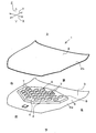
- FIG. 1 is a schematic exploded perspective view of an automobile hood according to the first embodiment of the present disclosure.
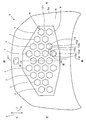
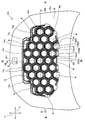
- FIG. 2 is a plan view of the reinforcing member of the automobile hood.
- FIG. 3 is a schematic cross-sectional view taken along the line III-III in FIG.
- FIG. 4 is an enlarged view of a part of FIG.
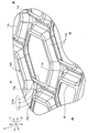
- FIG. 5 is an enlarged plan view of the periphery of one unit of the automobile hood.
- FIG. 6 is a diagram for explaining an example of the arrangement of the joints in the automobile hood.
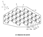
- FIG. 7A is a conceptual plan view showing a main part of a first modified example of the first embodiment, and shows a portion where a joint part is provided.
- 7B is a schematic plan view conceptually showing a part of the configuration of FIG.
- FIG. 8A is a conceptual plan view showing a main part of a second modified example of the first embodiment, and shows a portion where a joint part is provided.
- FIG. 8B is a schematic plan view conceptually showing a part of the configuration of FIG. 8A.
- FIG. 9A is a conceptual plan view showing a main part of a third modification example of the first embodiment, and shows a portion where a joint part is provided.
- FIG. 9B is a schematic plan view conceptually showing a part of the configuration of FIG. 9A.
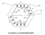
- FIG. 9C is a plan view of a main portion showing a modified example of the arrangement of the joint portion in the first embodiment, and shows a portion where the joint portion is provided.
- FIG. 9C is a plan view of a main portion showing a modified example of the arrangement of the joint portion in the first embodiment, and shows a portion where the joint portion is provided.
- FIG. 10 is a schematic exploded perspective view of an automobile hood according to the second embodiment of the present disclosure.
- FIG. 11 is a plan view of the reinforcing member of the automobile hood.
- FIG. 12 is a schematic cross-sectional view taken along the line XII-XII in FIG.
- FIG. 13 is a sectional view taken along the line XIII-XIII in FIG. 11, and the illustration of the portion appearing behind the section is omitted.
- FIG. 14 is an enlarged view of a part of FIG.
- FIG. 15 is an enlarged plan view of the periphery of one unit of the automobile hood.
- FIG. 16 is an enlarged perspective view of the periphery of one unit of the automobile hood.
- FIG. 17 is a diagram for explaining an example of the arrangement of the joints in the automobile hood.
- FIG. 18 is a conceptual plan view showing the main parts of the first modification of the second embodiment, showing the locations where the joints are provided.
- FIG. 19 is a conceptual plan view showing the main parts of the second modification of the second embodiment, and shows the location where the joint is provided.
- FIG. 20 is a conceptual plan view showing the main parts of the third modification of the second embodiment, showing the location where the joint is provided.
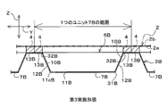
- FIG. 21A is a schematic plan view showing a main part of the third embodiment of the present disclosure.
- 21B is a sectional view taken along line XXIB-XXIB in FIG. 21A.
- FIG. 22A is a conceptual plan view showing a main part of Comparative Example 1, and shows a portion where a bonding part is provided.
- FIG. 22B is a conceptual plan view showing a main part of Comparative Example 2, and shows a portion where a bonding part is provided.
- the tensile rigidity is a press-formed product having a relatively gentle curved surface and a very large surface area with respect to the plate thickness, for example, when an external force is applied to an outer panel of an automobile hood, The rigidity of the panel.
- Tensile rigidity corresponds to the feeling of elastic resistance and flexural deformation when the panel is pushed by hand. This characteristic is usually represented by the amount of deflection when a load is applied, and the smaller the amount of deflection when a constant load is applied, the higher the tension rigidity.
- the dent resistance means the difficulty of leaving a dent after the load is removed when a local load is applied to the panel for some reason.
- the outer panel such as a door is strongly pressed with a finger or a palm, or when a stepping stone is hit during traveling.
- Dent is generated by plastically deforming a portion of the panel to which a load is applied. Therefore, when the strain of the panel reaches a certain level when the panel is loaded, the strain remains even after the unloading and a dent occurs.
- the minimum value of the load that causes a certain residual strain in the panel is called the dent load. The larger the dent load, the better the dent resistance.
- the definition of tensile rigidity is as described above. That is, the tenacity is the degree of flexibility of the panel. For example, when a panel of an automobile hood is pushed by hand, the panel is less likely to bend if the tension rigidity is high.
- the definition of dent resistance is as described above. That is, the dent resistance is the resistance to the formation of dents and flaws. For example, when pebbles hit the panel, if the dent resistance is low, the panel is easily dented or flawed.
- the occurrence of flexure which reflects the above-mentioned tensile rigidity of the outer panel of the automobile hood, mainly depends on the elastic modulus and the plate thickness of the panel.
- the low-strength material In the steel sheet, there is no difference in Young's modulus value between the low strength material and the high strength material. Therefore, simply replacing the low-strength material with the high-strength material does not improve the tensile rigidity.
- the low-strength material is replaced with the high-strength material, the dent resistance, which is a kind of resistance to plastic deformation, is improved.
- the influence of the steel material strength on the dent resistance is much smaller than the influence of the panel thickness on the dent resistance. Therefore, even if the low-strength material is simply replaced with the high-strength material, improvement in dent resistance cannot be expected so much.
- the tension rigidity and dent resistance of the panel the relationship between the panel thickness and the thickness of the panel will be further described.
- the limit thickness of the panel is about 0.65 mm in the case of steel plate.
- the thickness of the panel has not been made thinner than 0.65 mm so far. This is because the thinner the thickness of the panel, the greater the amount of bending of the panel when the panel is touched by hand for waxing or the like. In other words, it is because the car does not feel high-class.
- a reinforcing member has been attached to the vehicle inner surface side of the panel.
- the reinforcing member In order to improve the panel rigidity using a reinforcing member, it is preferable to increase the rigidity of the reinforcing member. However, if the plate thickness of the reinforcing member is increased to increase the rigidity of the reinforcing member, the reinforcing member becomes heavy, which is not preferable for reducing the weight of the automobile hood. Further, the dent resistance is not always improved even if the rigidity of the reinforcing member is increased. Due to such a problem, it is difficult to secure both the tension rigidity and the dent resistance while reducing the weight of the automobile hood even by simply using the reinforcing member.
- the inventor of the present application came to pay attention to the above-mentioned problems, and conducted further earnest research. Then, the idea of adopting a honeycomb structure as a reinforcing member of an automobile hood in consideration of the balance between strength and weight was obtained. The inventor of the present application continued to earnestly study even after arriving at forming the reinforcing member with a honeycomb structure, and first came up with a configuration satisfying both conditions of weight reduction and securing of tensile rigidity. As a result of further earnest research, the inventors have come up with a structure that satisfies all of weight reduction, ensuring tensile rigidity, and ensuring dent resistance.
- the present disclosure realizes an automobile hood that satisfies both the requirements for weight reduction and ensuring of tension rigidity. Then, in a more preferable form, an automobile hood that satisfies all of weight reduction, ensuring tensile rigidity, and ensuring dent resistance is realized. That is, the present disclosure, an example of which is shown below, has been conceived.
- FIG. 1 is a schematic exploded perspective view of an automobile hood 1 according to the first embodiment of the present disclosure.
- FIG. 2 is a plan view of the reinforcing member 3 of the automobile hood 1.
- FIG. 3 is a schematic cross-sectional view taken along the line III-III in FIG.
- the panel 2 which does not appear in FIG. 2 is shown by a two-dot chain line which is an imaginary line.
- FIG. 4 is an enlarged view of a part of FIG.
- FIG. 5 is an enlarged plan view of the periphery of one unit 7 of the automobile hood 1.
- FIG. 6 is a diagram for explaining an example of the arrangement of the joint portions 4 in the automobile hood 1.
- description will be given with reference to FIGS. 1 to 6 as appropriate.
- Automobile hood 1 is a front hood provided in the front part of the automobile and is also called a hood.
- the automobile provided with the automobile hood 1 is, for example, a passenger car.
- passenger vehicle examples include a sedan type passenger vehicle, a coupe type passenger vehicle, a hatchback type passenger vehicle, a minivan type passenger vehicle, an SUV (Sport Utility Vehicle) type passenger vehicle, and the like.
- the front, back, left, right, and top and bottom are referred to when the vehicle hood 1 is attached to the vehicle and the vehicle hood 1 is closed.
- the front is the direction in which the car moves forward.
- Rear is the direction in which the car moves backward.
- the right is the turning direction of the vehicle when the vehicle that is moving forward turns right.
- the left is the turning direction of the vehicle when the vehicle that is moving forward turns left.
- the vehicle width direction of the vehicle on which the vehicle hood 1 is mounted is referred to as the vehicle width direction X.
- the vehicle length direction of the vehicle on which the vehicle hood 1 is mounted is referred to as a vehicle length direction Y.
- the vehicle height direction of the vehicle on which the vehicle hood 1 is mounted is referred to as a vehicle height direction Z.
- the automobile hood 1 has a panel 2, a reinforcing member 3, and a joint portion 4 that joins the panel 2 and the reinforcing member 3.
- the panel 2 is a part of the outer surface of the automobile in the automobile hood 1.
- the panel 2 is made of, for example, a metal material such as a mild steel plate or a high-tensile steel plate.
- the high-tensile steel plate include a steel plate having a tensile strength of 340 MPa or more, and preferably a steel plate having a tensile strength of 440 MPa to 590 MPa.
- the panel 2 is formed, for example, by pressing one steel plate.
- the plate thickness t1 (plate thickness of the steel plate) of the panel 2 is set to 0.60 mm or less, preferably 0.50 mm or less, and more preferably 0.4 m0 m or less. ..
- the lower limit of the plate thickness t1 of the panel 2 is preferably 0.35 mm.
- the plate thickness t1 of the panel 2 is, for example, 0.35 mm to 0.60 mm. As described above, the thinner the plate thickness t1 of the panel 2, the lighter the automobile hood 1 can be made.
- the panel 2 may be an aluminum alloy plate.
- the plate thickness of the panel 2 is set to an equivalent value to the plate thickness of the panel 2 made of a steel plate from the viewpoints of tensile rigidity and dent resistance. More specifically, the tensile rigidity depends on the Young's modulus of the material and the plate thickness. Further, the dent resistance depends on the yield stress of the material and the plate thickness. Therefore, if the plate thickness of the aluminum alloy plate panel 2 is approximately 1.5 to 1.6 times the plate thickness of the steel plate panel 2, the aluminum alloy panel 2 will have a satisfactory tensile rigidity and dent resistance. It can be said that and the steel plate panel 2 are equivalent.
- the plate thickness t1 of the panel 2 (the plate thickness of the aluminum alloy plate) is set to 1.00 mm or less, preferably 0.80 mm or less, and more preferably 0.64 mm or less. Is set to.
- the lower limit of the plate thickness t1 of the panel 2 is preferably 0.50 mm.
- the plate thickness t1 of the panel 2 is, for example, 0.50 mm to 1.00 mm.
- the panel 2 has a central portion that is convex upward in the vehicle height direction Z.
- the reinforcing member 3 is joined to the lower surface 2a of the panel 2 to reinforce the panel 2.
- the reinforcing member 3 enhances both the tensile rigidity and the dent resistance of the panel 2. That is, in the present embodiment, the tensile rigidity and the dent resistance of the panel 2 are ensured by the reinforcing member 3 rather than by increasing the plate thickness t1 of the panel 2.
- the reinforcing member 3 is formed of, for example, a metal material such as a steel plate.
- the reinforcing member 3 is formed, for example, by pressing one steel plate.
- the reinforcing member 3 may be an integrally molded product, or may be formed by joining a plurality of members.
- the reinforcing member 3 is an integrally molded product.
- the plate thickness t2 (plate thickness of the steel plate) of the reinforcing member 3 is preferably 0.3 mm to 0.8 mm.
- the upper limit of the plate thickness t2 of the reinforcing member 3 is preferably 0.6 mm.
- the plate thickness t2 of the reinforcing member 3 may be smaller than the plate thickness t1 of the panel 2, may be the same as the plate thickness t1 of the panel 2, or may be larger than the plate thickness t1 of the panel 2.
- the reinforcing member 3 may be an aluminum alloy plate.
- the plate thickness of the reinforcing member 3 is set to an equivalent value with respect to the plate thickness of the reinforcing member 3 of the steel plate from the viewpoints of tensile rigidity and dent resistance. Therefore, as in the case of the panel 2, if the plate thickness of the reinforcing member 3 made of an aluminum alloy is approximately 1.5 to 1.6 times the plate thickness of the reinforcing member 3 made of a steel plate, the tensile rigidity and the durability are increased. It can be said that the reinforcing member 3 made of an aluminum alloy and the reinforcing member 3 made of a steel plate are equivalent from the viewpoint of dent property.
- the plate thickness t1 of the reinforcing member 3 (the plate thickness of the aluminum alloy plate) is 0.4 to 1.3 mm.
- the upper limit of the plate thickness t2 of the reinforcing member 3 is preferably 1.0 mm.
- the reinforcing member 3 has an outer peripheral portion 5, an inner peripheral portion 9 arranged so as to be surrounded by the outer peripheral portion 5, and a honeycomb structure 6 formed on the inner peripheral portion 9.
- the outer peripheral portion 5 is a portion arranged along the outer peripheral portion of the panel 2.
- the outer peripheral edge portion 5a of the panel 5 is received by the vehicle body (not shown) together with the outer peripheral portion of the panel 2.
- the load acting on the upper surface 2b of the panel 2 is received by the vehicle body via the reinforcing member 3.
- the inner peripheral portion 9 is formed in a shape protruding upward from the outer peripheral portion 5.
- the honeycomb structure 6 has a plurality of units 7.
- Each unit 7 is formed in a hexagonal ring shape in a plan view in the vehicle height direction Z.
- each unit 7 when simply expressed as a plan view, it means a plan view in the vehicle height direction Z.
- each unit 7 is formed into a substantially regular hexagon.
- a regular hexagon is a hexagon in which each side has the same length and the interior angle is 120 degrees.
- the term “substantially regular hexagon” means a hexagon that can be treated as a regular hexagon from the viewpoint of the tensile rigidity of the panel 2 and the viewpoint of dent resistance.
- the shape of each unit 7 is substantially the same. Note that in this case, “substantially the same” indicates that the configuration is the same except that the shape of each unit 7 is matched with the curved shape of the panel 2.
- Each unit 7 may be formed in a hexagon other than the regular hexagon.
- the hexagon other than the regular hexagon include a hexagon in which the length of each side is not uniform, and a hexagon in which the interior angles are not unified at 120 degrees.
- the length of the front end side and the length of the rear end side are set to a predetermined first length, and a predetermined second length different from the first length.
- a hexagon having four sides set respectively can be illustrated.
- the honeycomb structure 6 has a structure in which a plurality of hexagonal annular units 7 are densely arranged.
- “closest” means that when each side portion 10 of the unit 7 has another unit 7 adjacent thereto, the side portion 10 is arranged without a gap with one side portion 10 of the other unit 7.
- the tip 7a of the unit 7 forms the boundary of the unit 7 including the tip 7a. This boundary is formed in a hexagonal shape in a plan view. With such a close-packed hexagonal arrangement, the honeycomb structure 6 can withstand loads in all directions including the vehicle height direction Z in substantially the entire area in plan view.
- the plurality of units 7 are formed symmetrically in the vehicle width direction X as a whole. Specifically, in the present embodiment, three units 7 are arranged in the front and rear in the center in the vehicle width direction X. Then, in a plan view, the plurality of units 7 are arranged symmetrically in the vehicle width direction X with reference to an imaginary line A1 that extends forward and backward through the center of the three units 7 in the vehicle width direction X. Not limited to this, since the tension rigidity, the dent resistance, and the mass do not depend on the direction of the unit 7, there is no restriction on the direction of the unit 7.
- four units 7 arranged in the vehicle length direction Y are arranged in order from the three units 7 arranged at the center position in the vehicle width direction X toward the right side, and further in the vehicle length direction Y.
- Three units 7 lined up are arranged, two units 7 lined up in the vehicle length direction Y are arranged, and two units 7 lined up in the vehicle length direction Y are arranged.
- four units 7 arranged in the vehicle length direction Y are sequentially arranged from the three units 7 arranged at the center position in the vehicle width direction X toward the left side, and further, the vehicle length.
- Three units 7 arranged in the direction Y are arranged, two units 7 arranged in the vehicle length direction Y are arranged, and two units 7 arranged in the vehicle length direction Y are arranged.
- a maximum of four units 7 are arranged in the vehicle length direction Y, and nine units 7 are arranged in the vehicle width direction X.
- the units 7 are arranged in three or more rows in the vehicle length direction Y from the viewpoint of arranging the units 7 in the closest arrangement. For the same reason, it is preferable that the units 7 are arranged in five or more rows in the vehicle width direction X.
- Each unit 7 is adjacent to the lower surface 2a of the panel 2.
- Each unit 7 has six side portions 10 (10a to 10f).
- the front side portion 10a and the rear side portion 10d respectively extend along the vehicle width direction X.
- the remaining four side portions 10 extend in a direction inclined with respect to the vehicle length direction Y in a plan view.
- the six sides 10 form a hexagonal flange. Then, the inner ends of the six side parts 10 form an annular end as a whole.
- each unit 7 at least a part of the side portion 10 is adhered to the joint portion 4 on the upper surface 101 of the side portion 10, and is adhered to the panel 2 via the joint portion 4.
- first ridgeline 31 as a ridgeline formed at the outer peripheral end (tip 7a) of each of the six sides 10.
- the first ridgeline 31 is a hexagonal annular ridgeline.
- the first ridgeline 31 is an example of a “hexagonal ring-shaped ridgeline”.
- the length L1 of one side of the first ridgeline 31 is set to 40 mm or more and 75 mm or less in the present embodiment.
- the span in which one unit 7 supports the panel 2 is short, and the tension rigidity can be increased.
- the tolerance of the deflection of the panel 2 becomes small, and the dent resistance decreases.
- the reinforcing member 3 becomes heavy.
- the length L1 of one side of the first ridgeline 31 exceeds the above upper limit, the span in which one unit 7 supports the panel 2 becomes too long, and as a result, it is difficult to secure sufficient tensile rigidity. Then, by setting the length L1 of one side of the first ridgeline 31 within the above range, it is possible to secure sufficient tension rigidity and sufficient dent resistance while making the reinforcing member 3 lighter. Therefore, in the automobile hood 1, it is possible to secure sufficient tension rigidity and dent resistance for the panel 2 while achieving weight reduction of the panel 2.
- the joining portion 4 is an adhesive in the present embodiment.
- this adhesive include a mastic sealer (mastic adhesive).
- An example of this mastic sealer is a resin adhesive.
- the adhesive may have a property of being cured at room temperature (for example, 20 degrees Celsius), or may have a property of being cured by a heating process or a drying process.
- the joint part 4 is provided so as to secure both the rigidity and the dent resistance while achieving the weight reduction of the automobile hood 1.
- the joint portion 4 is provided on at least two side portions 10 of the six side portions 10 that are parallel to each other. Then, in the present embodiment, in each unit 7, the joint portion 4 is provided on all of the six side portions 10.
- the joint portion 4 is provided on the upper surface 101 of each side portion 10, the joint portion 4 is provided over the entire area of the side portion 10 in the longitudinal direction, and the joint portions 4 provided on the adjacent side portions 10 are integrated. ing.
- the joint portion 4 has a hexagonal shape.
- the thickness t3 of the joint portion 4 is, for example, about several mm, which is an extremely large value with respect to both the plate thickness t1 of the panel 2 and the plate thickness t2 of the reinforcing member 3. Therefore, the joint portion 4 cannot be ignored in terms of material cost and weight in the automobile hood 1. Therefore, from the viewpoint of material cost and weight reduction of the automobile hood 1, it is preferable that the amount of the joint portion 4 used be as small as possible.
- the joint portion 4 is also a load transmission portion provided for transmitting the load from the panel 2 to the unit 7. Therefore, from the viewpoint of achieving all of weight reduction, improvement in tensile rigidity, and improvement in dent resistance, it is possible to define a more preferable use mode of the joint portion 4 in each unit 7.
- FIG. 7A is a conceptual plan view showing a main part of a first modified example of the first embodiment of the present disclosure, and shows a location where the joint part 4 is provided.
- 7B is a schematic plan view conceptually showing a part of the configuration of FIG. 7A.
- the contents shown in FIG. 7A and the contents shown in FIG. 7B are the same.
- the joint portion 4 is provided on a part of the side portions 10 of the six side portions 10 (10a to 10f) of each annular unit 7.
- the joining portion 4 is provided on at least two side portions 10 of the six side portions 10 that face each other in parallel, and the two side portions 10 are separated from each other. ing.
- the joint portion 4 extends in a linear streak shape along the longitudinal direction of the side portion 10.
- the length W2 of the joint portion 4 is set to be equal to or more than the above lower limit, it is possible to sufficiently secure the bonding strength between the side portion 10 where the joint portion 4 is provided and the panel 2.
- the step of adhering the joint portion 4 to the panel 2 and the side portion 10 by heating is adopted, thermal distortion occurs in the panel 2 and the reinforcing member 3 due to the heating in the heating step of the joint portion 4.
- the joint portion 4 only on a part of the six side portions 10 of the unit 7, the thermal strain can be reduced.
- each unit 7 the joint portion 4 is provided on a part of the six side portions 10 and the remaining side portions 10 are connected to each other. Is not provided. The rest of the side portion 10 directly faces the panel 2 vertically.
- the joining portion 4 includes, among the six side portions 10, a front side portion 10a and a rear side portion 10d extending in parallel with each other, a right rear side portion 10c and a left front side portion 10f extending in parallel with each other, It is provided in. That is, the joint portions 4 are provided on the four side portions 10 of the unit 7 excluding the right front side portion 10b and the left rear side portion 10e.
- the joint-unset region 14 is provided from the left rear side to the front right side (toward the diagonally right front side).
- the honeycomb structure 6 is provided with a plurality of aggregates 15 of zigzag streak-shaped joint portions 4 extending from the left rear to the right front. With such a configuration of the honeycomb structure 6, it is possible to satisfy the three requirements of weight reduction, ensuring tensile rigidity, and ensuring dent resistance at a high level.
- the overall arrangement of the plurality of joint portions 4 in the first modification shown in FIGS. 7A and 7B may be symmetrically replaced in the vehicle width direction X.
- the joint portion 4 may be arranged in the mode shown in the second modified example of FIGS. 8A and 8B.
- the joint portion 4 includes, for example, a right front side portion 10b and a left rear side portion 10e, which are two sides of the six side portions 10 of the unit 7 and extend in parallel to each other, and these two side portions. It is provided on the two side portions 10 that are in contact with either end of any one of the portions 10. That is, the joint portions 4 are provided on the four side portions 10 of the unit 7.
- the first unit 21 as an assembly of the units 7 in which the joint portion 4 is not provided on the rear side portion 10d and the left front side portion 10f is joined to the front side portion 10a and the right rear side portion 10c.
- the second unit 22 as an aggregate of the units 7 in which the section 4 is not provided is provided.
- the first unit 21 the units 7 are connected from the rear left toward the front right.
- the second unit 22 the units 7 are connected from the left rear to the front right.
- the 1st unit 21 and the 2nd unit 22 are arranged by turns.
- the overall arrangement of the plurality of joint portions 4 in the second modification shown in FIGS. 8A and 8B may be symmetrically replaced in the vehicle width direction X.
- the joining portions 4 are provided on the four side portions 10 of each unit 7 and the joining portions 4 are not provided on the two side portions 10.
- the joint portion 4 may be provided on two of the six side portions 10. That is, a pair of two side portions 10, 10 facing each other in parallel in a plan view is provided as the joint portion 4. The remaining four side portions 10 are directly adjacent to the panel 2 because the joint portion 4 is not provided.
- the joint portion 4 is provided, for example, only on the right rear side portion 10c and the left front side portion 10f of the six side portions 10 of the unit 7 which extend parallel to each other. There is. Therefore, in each unit 7, the joint portions 4 are not provided on the four side portions 10. As described above, in each unit 7, if the joint portion 4 is provided on the two side portions 10 (10c, 10f) that are part of the six side portions 10 and are parallel to each other, the weight is reduced, In addition, it is possible to satisfy the three requirements of ensuring the tensile rigidity and the dent resistance at a high level.
- the joining portions 4 are provided only on the front side 10a and the rear side 10d which are parallel to each other among the six sides 10.
- a modified example in which the joint portion 4 is provided only on the right front side portion 10b and the left rear side portion 10e which are parallel to each other.
- the bonding portion 4 may be provided on the other side portion 10. In this case, of the six side portions 10, The joint portion 4 is provided on the three side portions 10.
- FIG. 9C is a plan view of a main portion showing a modified example of the arrangement of the joint portion 4 in the first embodiment, and shows a portion where the joint portion 4 is provided.
- the joint portions 4 may be intermittently arranged in a dot shape.
- FIG. 9C shows, as an example, an example in which the dot-shaped joint portions 4 are arranged on the front side portion 10a, the right front side portion 10b, the rear side portion 10d, and the left rear side portion 10e, respectively.
- the joint portion 4 is composed of a plurality of joint portion pieces 4a.
- the joining piece 4a is arranged intermittently along the extending direction of the side portion 10.
- the front side part 10a and the rear side part 10d are two parallel sides
- the right front side part 10b and the left rear side part 10e are two parallel sides.
- the front side portion 10a and the rear side portion 10d which are parallel to each other are arranged such that the joint pieces 4a are arranged in the direction parallel to the side portions 10a and 10d (left and right direction in FIG. 9C).
- the center of one joint piece 4a be disposed at the longitudinal center CP of each of the side portions 10a and 10d.
- the right front side part 10b and the left rear side part 10e which are parallel to each other are arranged in the direction parallel to the side parts 10b and 10e (the left oblique front direction in FIG. 9C), and the arrangement position of the joint piece 4a is It is preferable that they are aligned.
- the center of one joint piece 4a is disposed at the center of each of the sides 10b and 10e in the longitudinal direction.
- the side portion 10 provided with the joint 4 is 20% or more of the side portion 10 in the extending direction of the side portion 10. Is in contact with the joint portion 4 over the range.
- both the tensile rigidity and the dent resistance of the panel 2 can be further improved.
- the joint portion 4 has a linear shape that continuously extends on the side portion 10, when the joint portion 4 is provided in a dot shape at the corner portion of the hexagon, or the joint portion 4 is formed in a dot shape at the center of the side portion 10. Both the tensile rigidity and the dent resistance of the panel 2 can be further increased as compared with the case where the panel 2 is provided.
- the plate thickness t1 of the steel plate panel 2 is 0.6 mm or less.
- the tension rigidity and the dent resistance obtained from the rigidity of the panel 2 itself drops extremely. More specifically, the tensile rigidity of the panel 2 depends on the Young's modulus and the plate thickness of the panel 2, and particularly changes with the square of the plate thickness.
- the tensile rigidity that can be secured by the panel 2 alone is extremely reduced. This decrease in rigidity is particularly noticeable when the panel 2 is pressed by a human hand, which causes deterioration of the commercialability of the automobile.
- the tensile rigidity of the steel panel 2 there is a critical significance between the plate thickness t1 of 0.6 mm and 0.65 mm. Even when the thin panel 2 having the plate thickness t1 of 0.6 mm or less is used as in the present embodiment, the reinforcing member 3 for reinforcement and stiffening and the panel 2 are combined to form the automobile hood 1.
- the tensile rigidity and dent resistance that are substantially the same as when the plate thickness t1 of the panel 2 is 0.65 mm can be secured. Moreover, since the panel thickness t1 of the panel 2 is reduced, the weight of the vehicle hood 1 can be reduced by reducing the weight of the panel 2.
- the steel panel 2 and the reinforcing member 3 are superior in material cost to the aluminum alloy panel and the reinforcing member. Further, in the case of an automobile hood made of an aluminum alloy, the idea that the reinforcing member below the panel secures the tensile rigidity has not existed in the first place. Moreover, since the Young's modulus of aluminum alloy is lower than that of steel, the rigidity of aluminum alloy is lower than that of steel. Therefore, in order to secure the rigidity equivalent to that of the steel automobile hood 1 in the aluminum alloy automobile hood, it is necessary to further increase the plate thickness of the member. Therefore, in order to satisfy both the tensile rigidity and the dent resistance in the aluminum alloy panel, the plate thickness increases.
- the viewpoint of improving both the tensile rigidity and the dent resistance while reducing the plate thicknesses of the panel 2 and the reinforcing member 3 as in the present embodiment does not exist in the aluminum alloy automobile hood.
- the thickness of the panel and the reinforcing member of the steel plate and the panel and the reinforcing member of the aluminum alloy plate can be set so that the performance becomes equivalent. Therefore, in this embodiment, the panel 2 and the reinforcing member 3 may be steel plates or aluminum alloy plates.
- FIG. 10 is a schematic exploded perspective view of the automobile hood 1 according to the second embodiment of the present disclosure.
- FIG. 11 is a plan view of the reinforcing member 3A of the automobile hood 1.
- FIG. 12 is a schematic cross-sectional view taken along the line XII-XII in FIG.
- FIG. 13 is a sectional view taken along the line XIII-XIII in FIG. 11, and the illustration of the portion appearing behind the section is omitted. Note that, in FIGS. 12 and 13, the panel 2 that does not appear in FIG. 11 is indicated by a two-dot chain line that is an imaginary line.
- FIG. 14 is an enlarged view of a part of FIG.
- FIG. 15 is an enlarged plan view of the periphery of one unit 7A of the automobile hood 1.
- the other units 7A other than the one unit 7A in the center are shown by a thinner line than the unit 7A in the center so as to be easily distinguished from the unit 7A in the center.
- FIG. 16 is an enlarged perspective view of the periphery of one unit 7A of the automobile hood 1.
- FIG. 17 is a diagram for explaining an example of the arrangement of the joint portions 4 in the automobile hood 1.
- description will be given with reference to FIGS. 10 to 17 as appropriate.
- the reinforcing member 3A has an outer peripheral portion 5 and a honeycomb structure 6A arranged so as to be surrounded by the outer peripheral portion 5.
- the inner peripheral edge portion 5b of the outer peripheral portion 5 is a portion that is arranged so as to surround the honeycomb structure 6A and is joined to the honeycomb structure 6A.
- the honeycomb structure 6A has a three-dimensional structure provided to receive a load acting on the upper surface 2b of the panel 2.
- the honeycomb structure 6A of the second embodiment is formed by combining members having a V-shaped cross section (hat-shaped cross section).
- the honeycomb structure 6A has a plurality of units 7A and a plurality of partial units 8 that are adjacent to the inner peripheral edge portion 5b of the outer peripheral portion 5 and continuous with the outer peripheral portion 5.
- the unit 7A adjacent to the outer peripheral portion 5 of the reinforcing member 3 is connected to the outer peripheral portion 5 directly or through the partial unit 8.
- the partial unit 8 has a configuration corresponding to a configuration in which a part of the unit 7A is cut out along the circumferential direction of the hexagonal unit 7A.
- the partial unit 8 has a side portion similar to the side portion 10A of the unit 7A. The side portion is continuous with the inner peripheral edge portion 5b of the outer peripheral portion 5.
- Each unit 7A is formed in a hexagonal ring shape in a plan view in the vehicle height direction Z.
- each unit 7A is substantially formed in a regular hexagon.
- the shape of each unit 7A is substantially the same.
- Each unit 7A may be formed in a hexagon other than the regular hexagon.
- the honeycomb structure 6A has a structure in which a plurality of hexagonal annular units 7A are densely arranged. Specifically, the unit 7A is partitioned from other units 7A in a top plate 13 described later. As shown in FIG. 15, the tip 13b of the top plate 13 forms a boundary of the top plate 13 including the tip 13b. This boundary is formed in a hexagonal shape in a plan view.
- the plurality of units 7A are formed symmetrically in the vehicle width direction X as a whole. Specifically, the number and the arrangement of the units 7A are the same as the number and the arrangement of the units 7A in the first embodiment.
- Each unit 7A has six sides 10A (10aA to 10fA).
- Each side portion 10A (10aA to 10fA) has a floor 11, a vertical wall 12, and a top plate 13.
- Floor 11 is adjacent to panel 2 and is the portion of side portion 10A that is arranged closest to panel 2.
- the floor 11 is a strip-shaped portion.
- the floor 11 is a flange portion of the side portion 10A, and the floor 11 of the six side portions 10A forms a hexagonal flange.
- the inner ends 11a of the six floors 11 form an annular end centered on the center of the annular unit 7 as a whole, and form the end located on the center side of the unit 7. There is.
- the outer end portion 11c of the floor 11 has an imaginary line V1 including the upper surface 11b (straight portion) of the floor 11 and the upper surface of the vertical wall 12.
- the intersection of the virtual lines V1 and V2 is not only the outer end 11c but also the first ridge line 31.
- the outer end portion 11c is a virtual end portion. That is, in the present embodiment, the first ridgeline 31 is a virtual line.
- the outer end 11c serves as a connection point between them. In this case, the first ridgeline 31 is a solid line.
- the first ridge line 31 is a hexagonal ring-shaped ridge line.
- the first ridgeline 31 is also a part of the floor 11 and a part of the vertical wall 12.
- the first ridgeline 31 is adjacent to the panel 2.
- Both ends in the longitudinal direction of the floor 11 are formed in a curved shape in a plan view, and are smoothly continuous with the floor 11 of the adjacent side portion 10A.
- the floor 11 of at least a part of the side portion 10A is adhered to the joint portion 4 on the upper surface 11b, and is adhered to the panel 2 via the joint portion 4.
- a vertical wall 12 extends downward from the floor 11.
- the vertical wall 12 is arranged between the floor 11 and the top plate 13, and connects the floor 11 and the top plate 13.
- the vertical wall 12 is provided over the entire area in the longitudinal direction of the side portion 10A where the vertical wall 12 is provided.
- the angle ⁇ 1 formed by the vertical wall 12 with respect to the floor 11, for example, the angle ⁇ 1 formed by the upper side surface 12a of the vertical wall 12 and the upper surface 11b of the floor 11 is preferably set within a range of 40 degrees to 90 degrees. ..
- the vertical wall 12 can sufficiently function as a pillar, and thus the load transmitted from the panel 2 to the floor 11 can be received by the vertical wall 12 with a small deformation amount. it can.
- the unit 7 can have a shape that widens toward the bottom (a shape in which the distance between the vertical walls 12 facing each other toward the lower side in the vehicle height direction Z becomes wider). Therefore, it is easy to mold.
- the length of the vertical wall 12 in the vehicle height direction Z is a component in the vehicle height direction Z of the distance between the first ridgeline 31 and the second ridgeline 32, and is about 16 mm in this embodiment.
- the second ridgeline 32 is the intersection of the virtual line V3, which is the tangent to the top of the lower side surface 13c of the top plate 13, and the virtual line V2.
- the intersection of the virtual lines V2 and V3 is not only the second ridgeline 32 but also the inner end portion 13d of the top plate 13.
- the second ridgeline 32 is a virtual ridgeline.
- the second ridgeline 32 is a solid line.
- the second ridgeline 32 can be said to be a part of the vertical wall 12 and also a part of the top plate 13.
- the second ridgeline 32 is a hexagonal ring-shaped ridgeline like the first ridgeline 31.
- the second ridgeline 32 is located on the outer periphery of the lower end of the vertical wall 12 and is separated from the panel 2.
- the first ridgeline 31 is an example of “a hexagonal ring-shaped ridgeline between the vertical wall and the floor”, and is a ridgeline at the end of the vertical wall 12 on the floor 11 side.
- the first ridgeline 31 and the second ridgeline 32 are similar to each other in a plan view. In plan view, the total length of the second ridgeline 32 is longer than the total length of the first ridgeline 31.
- the distance from the panel 2 to the second ridgeline 32 is longer than the distance from the panel 2 to the first ridgeline 31.
- the thickness of the unit 7A (the length in the vehicle height direction Z) can be set.
- the floor 11 is continuous with the upper end of the vertical wall 12.
- a top plate 13 is continuous with the lower end of the vertical wall 12.
- the top plate 13 is the portion of the unit 7A that is most distant from the panel 2.
- the top plate 13 is formed in a curved shape that is convex downward, or in a shape that extends substantially horizontally.
- the top plate 13 is provided over the entire area in the longitudinal direction of the side portion 10 on which the vertical wall 12 is provided.
- the floor 11, the vertical wall 12, and the top plate 13 are arranged in this order from the inner side to the outer side of the unit 7A in the radial direction.
- the tip 13b of the top plate 13 in one unit 7A is integral with the tip 13b of the top plate 13 in the adjacent unit 7.
- the arrangement of the joint portions 4 in the second embodiment is the same as the arrangement of the joint portions 4 in the first embodiment. That is, the joint portion 4 is provided on the six side portions 10A and at least the two side portions 10A parallel to each other. And in this embodiment, the junction part 4 is provided in all the six side parts 10A in each unit 7A. In the present embodiment, on the upper surface 11b of the floor 11 of each side portion 10A, the joint portion 4 is provided over the entire area of the side portion 10A in the longitudinal direction, and the joint portions 4 provided on the adjacent side portions 10A are adjacent to each other. Are integrated. Thus, in this embodiment, the joint portion 4 in each unit 7A has a hexagonal shape. However, the joint portion 4 of each unit 7A is separated from the joint portion 4 of another unit 7A, which is different from the arrangement of the joint portions 4 in the first embodiment.
- the floor 11 of the hat-shaped reinforcing member 3A functions as a flange.
- the joint portion 4 With the floor 11 as a joint portion, a closed cross section is formed by the six floors 11 and the panel 2 forming the hexagonal shape.
- the rigidity becomes higher than the structure in which the joining portion 4 is provided on the top plate 13 to join the panel 2 and the top plate 13 (the configuration in which the reinforcing member 3A and the panel 2 form an open cross section), and the tension rigidity and Both dent resistance can be increased.
- the same arrangement as that of the joint portion 4 in the first modified example of the first embodiment shown in FIGS. 7A and 7B may be adopted.
- An example of such an arrangement is shown in FIG.
- the same arrangement as that of the joint portion 4 in the second modified example of the first embodiment shown in FIGS. 8A and 8B may be adopted.
- An example of such an arrangement is shown in FIG.
- the same arrangement as that of the joint portion 4 in the third modified example of the first embodiment shown in FIGS. 9A and 9B may be adopted.
- An example of such an arrangement is shown in FIG.
- FIG. 21A is a schematic plan view showing a main part of the third embodiment of the present disclosure.
- 21B is a sectional view taken along line XXIB-XXIB in FIG. 21A.
- the configuration not shown in FIG. 21A is shown by an alternate long and two short dashes line.
- the third embodiment is a modification of the second embodiment.
- the difference of the third embodiment from the second embodiment is that the top plate 13B of the third embodiment is joined to the panel 2 by the joining portion 4.
- the reinforcing member 3B has an outer peripheral portion 5 (not shown in FIGS. 21A and 21B) and a honeycomb structure 6B arranged so as to be surrounded by the outer peripheral portion 5.
- the honeycomb structure 6B of the third embodiment is formed by combining members having a V-shaped cross section (hat-shaped cross section).
- the honeycomb structure 6B has a plurality of units 7B.
- Each unit 7B is formed in a hexagonal ring shape in a plan view in the vehicle height direction Z.
- each unit 7B is formed into a substantially regular hexagon.
- the shape of each unit 7B is substantially the same.
- the honeycomb structure 6B has a structure in which a plurality of hexagonal annular units 7B are densely arranged. Specifically, the unit 7B is partitioned from the other units 7B in the top plate 13B.
- the tip 13bB of the top plate 13B forms a boundary of the top plate 13B including the tip 13bB. This boundary is formed in a hexagonal shape in a plan view.
- the number and arrangement of the plurality of units 7B are the same as the number and arrangement of the units 7B in the second embodiment.
- Each unit 7B has six sides 10B (10aB to 10fB).
- Each side portion 10B (10aB to 10fB) has a floor 11B, a vertical wall 12B, and a top plate 13B.
- the vertical wall 12B is connected to the floor 11B and the top plate 13B in an angular shape.
- the boundary between the vertical wall 12B and the floor 11B is defined by this angular portion.
- the boundary between the vertical wall 12B and the top plate 13B is defined by this angular portion.
- the vertical wall 12B may be connected to each of the floor 11B and the top plate 13B in a curved shape.
- the floor 11B is separated from the panel 2 and is a part of the side portion 10B which is arranged most distant from the panel 2.
- the outer ends 11cB of the six floors 11B form an annular end as a whole.
- the line connecting the edges of the outer end portion 11cB is the first ridgeline 31B.
- the first ridgeline 31B is a hexagonal annular ridgeline in plan view.
- the first ridgeline 31B is also a part of the floor 11B and a part of the vertical wall 12B.
- a vertical wall 12B extends upward from the floor 11B.
- the vertical wall 12B is arranged between the floor 11B and the top plate 13B, and connects the floor 11B and the top plate 13B.
- the vertical wall 12B is provided over the entire region in the longitudinal direction of the side portion 10B where the vertical wall 12B is provided.
- the vertical wall 12B is formed in a shape that widens toward the end as it goes upward (a shape in which the distance between the vertical walls 12B and 12B facing each other increases toward the upper side in the vehicle height direction Z).
- the second ridgeline 32B is a ridgeline at the boundary between the lower side surfaces of the top plate 13B and the vertical wall 12B.
- the second ridgeline 32B can be said to be a part of the vertical wall 12B and also a part of the top plate 13B.
- the second ridgeline 32B is a hexagonal annular ridgeline, like the first ridgeline 31B.
- the floor 11B is continuous with the lower end of the vertical wall 12B.
- a top plate 13B is continuous with the upper end of the vertical wall 12B.
- the top plate 13B is the portion of the unit 7B closest to the panel 2.
- the top plate 13B is formed in a flat plate shape.
- the top plate 13B is provided over the entire area in the longitudinal direction of the side portion 10B where the vertical wall 12B is provided.
- the top plate 13B is a flange portion of the side portion 10B, and the top plates 133B of the six side portions 10B form a hexagonal flange.
- the top plate 13B of at least a part of the side portion 10B is adhered to the joint portion 4 on the upper surface of the top plate 13B, and is adhered to the panel 2 via the joint portion 4. ..
- the arrangement of the joint portions 4 in the third embodiment is the same as that in the second embodiment and its modification, and therefore the description thereof is omitted.
- the top plate 13B of the unit 7B is used as the joining portion where the joining portion 4 is provided.
- the shape of the portion where the joint portion 4 (adhesive) is placed is simpler than the configuration in which the joint portion 4 is provided on the floor 11B using the floor 11B as a flange.
- the joining portion 4 can be easily installed on the top plate 13B.
- the shape model of the automobile hood 1 of the second embodiment shown in FIG. 17 was created on a computer using CAD (Computer Aided Design) software. That is, the automobile hood 1 including the panel 2, the reinforcing member 3A, and the joint portion 4 was created on a computer, and the present disclosure example 1 was obtained. Then, by performing CAE (Computer Aided Engineering) analysis on the shape model of the automobile hood 1, that is, by performing computer simulation, the tensile rigidity and the dent resistance were evaluated. The characteristics of each part are as follows.
- Panel 2 and reinforcing member 3A Steel plate.
- Present Disclosure Example 1 Sequence A. The arrangement shown in the second embodiment of FIG. The joint portion 4 is arranged on all of the six side portions 10A of the unit 7A.
- Present Disclosure Example 2 Sequence B. The arrangement shown in the first modification of the second embodiment of FIG. The joint portion 4 is arranged on the four side portions 10A of the unit 7A.
- Present Disclosure Example 3 Sequence C. The arrangement shown in the second modification of the second embodiment of FIG. The joint portion 4 is arranged on the four side portions 10A of the unit 7A.
- Present Disclosure Example 4 Sequence D. The arrangement shown in the third modification of the second embodiment of FIG. The joint portion 4 is arranged on two parallel side portions 10A of the unit 7A.
- Comparative Example 1 Sequence E. The arrangement shown in Comparative Example 1 of FIG.
- Comparative Example 2 Sequence F. The arrangement shown in Comparative Example 2 of FIG. 22B.
- the joint portion 4 is arranged on only one side portion 10A of the unit 7A.
- the joint portion 4 has the right front side portion as the two sides (1) extending out of the six side portions 10A (10aA to 10fA) in the unit 7A that are not parallel to each other. 10bA and the left front side portion 10fA, or (2) the right rear side portion 10cA and the left rear side portion 10eA, which are two sides extending in a manner not parallel to each other.
- the first unit 51A as an assembly of the units 7A in which the joint portion 4 is provided on the right front side portion 10bA and the left front side portion 10fA described in (1) above and (2) above.
- the second unit 52A which is the assembly of the units 7A in which the joint portion 4 is provided on the right rear side portion 10cA and the left rear side portion 10eA, described above.
- the units 7A are continuous from the left rear to the front right.
- the units 7A are continuous from the left rear to the right front.
- the 1st unit 51A and the 2nd unit 52A are arranged by turns.
- Comparative Example 2 will be described in more detail.
- the joint portion 4 is provided only on the right front side portion 10bA or only the left rear side portion 10eA of the six side portions 10A (10aA to 10fA) of the unit 7A.
- the joint portion 4 is provided only on one side portion 10A in the unit 7A.
- the first unit 61A as an assembly of the units 7A in which the joining portion 4 is provided only in the right front side portion 10bA and the unit in which the joining portion 4 is provided only in the left rear side portion 10eA.
- the second unit 62A which is an assembly of 7A, is provided.
- the units 7A are continuous from the left rear to the front right. Similarly, in the second unit 62A, the units 7A are connected from the left rear to the front right. And the 1st unit 61A and the 2nd unit 62A are arranged by turns.
- Table 1 shows the evaluation results of the tensile rigidity, the dent resistance, and the amount of the joint 4 used.
- Comparative Examples 1 and 2 use a small amount of the joint portion 4 and are preferable in terms of weight reduction, but it can be said that the reinforcing member 3A fulfills the function of reinforcing the panel 2. Absent. Therefore, both tensile rigidity and dent resistance were evaluated as poor.
- the steel plate panel 2 and the steel plate reinforcing member 3A and the aluminum alloy plate panel 2 and the aluminum alloy plate reinforcing member 3A have different plate thicknesses from the viewpoint of tensile rigidity and dent resistance.
- By setting an equivalent thickness it is possible to secure the same tensile rigidity and dent resistance. Therefore, it is clear that similar results can be obtained by applying the present invention to an aluminum alloy plate.
- the present disclosure can be widely applied as an automobile hood.
Landscapes
- Engineering & Computer Science (AREA)
- Chemical & Material Sciences (AREA)
- Combustion & Propulsion (AREA)
- Transportation (AREA)
- Mechanical Engineering (AREA)
- Superstructure Of Vehicle (AREA)
Abstract
自動車フードにおいて軽量化を達成しつつ、十分な張り剛性を確保する。自動車フード1は、パネル2と、補強部材3と、パネル2と補強部材3とを接合している接合部4とを有する。補強部材3は、六角形の環状の複数のユニット7が最密に配置された構造を含む。接合部4は、環状のユニット7の6つの辺部10のうち少なくとも互いに平行な2つの辺部10に設けられる。
Description
本開示は、自動車フードに関する。
自動車フードが知られている(例えば、特許文献1,2参照)。
特許文献1には、車両のフードパネル構造が開示されている。このフードパネル構造は、歩行者がフードパネルに衝突したときに歩行者に与える傷害値を低減することを主眼としている。
特許文献2には、自動車用外装品としての自動車用フードが開示されている。この自動車用フードは、歩行者が自動車用フードに接触したときに、自動車の内方へ少ない量変形するだけで接触のエネルギーを吸収することを主眼としている。
自動車フードは、更なる軽量化、および、張り剛性の向上を要求されている。しかしながら、軽量化のために鋼板製の自動車フードのパネルを0.6mmより薄くすると、張り剛性が無視できないほどに低下する。
特許文献1,2の何れにおいても、軽量化を達成しつつ十分な張り剛性を確保する観点での課題および構成は、何ら開示されていない。例えば、特許文献1では、[0029]段落において、インナーパネルとアウターパネルが接着剤で接合されることが開示されている。しかしながら、張り剛性の観点で接着剤の位置を決める観点は何ら存在していない。このように、特許文献1では、接着剤の配置が張り剛性に与える影響は考慮されていない。
本開示の目的の一つは、自動車フードにおいて軽量化を達成しつつ、パネルの十分な張り剛性を確保することにある。
本開示は、下記の自動車フードを要旨とする。
(1)パネルと、
補強部材と、
前記パネルと前記補強部材とを接合している接合部と、を備え、
前記補強部材は、六角形の環状の複数のユニットが最密に配置された構造を含み、
接合部は、前記環状のユニットの6辺のうち少なくとも互いに平行な2つの辺に設けられる、
自動車フード。
補強部材と、
前記パネルと前記補強部材とを接合している接合部と、を備え、
前記補強部材は、六角形の環状の複数のユニットが最密に配置された構造を含み、
接合部は、前記環状のユニットの6辺のうち少なくとも互いに平行な2つの辺に設けられる、
自動車フード。
(2)前記接合部は、前記環状のユニットの6辺における一部の辺に設けられている、前記(1)に記載の自動車フード。
(3)一つの前記六角形の環状のユニットにおいて、4つの辺は前記接合部に接合され、2つの互いに離れた辺は直接前記パネルに隣接する、前記(2)に記載の自動車フード。
(4)前記六角形の環状のユニットにおいて、前記接合部が設けられている前記辺は、前記辺の延びる方向に関して、前記辺の20%以上の範囲に亘って前記接合部と接している、前記(1)~(3)の何れか1項に記載の自動車フード。
(5)前記パネルは、鋼板であり、
前記パネルの板厚が0.35mm~0.60mmである、前記(1)~(4)の何れか1項に記載の自動車フード。
前記パネルの板厚が0.35mm~0.60mmである、前記(1)~(4)の何れか1項に記載の自動車フード。
(6)前記パネルは、アルミ合金板であり、
前記パネルの板厚が0.50mm~1.00mmである、前記(1)~(4)の何れか1項に記載の自動車フード。
前記パネルの板厚が0.50mm~1.00mmである、前記(1)~(4)の何れか1項に記載の自動車フード。
(7)前記ユニットは、床と、縦壁と、天板と、を有し、
前記床は、前記パネルに隣接し、
前記天板と前記パネルとは離隔しており、
前記縦壁は、前記床と前記天板の間に配置されている、前記(1)~(6)の何れか1項に記載の自動車フード。
前記床は、前記パネルに隣接し、
前記天板と前記パネルとは離隔しており、
前記縦壁は、前記床と前記天板の間に配置されている、前記(1)~(6)の何れか1項に記載の自動車フード。
本開示によれば、自動車フードにおいて軽量化を達成しつつ、十分な張り剛性を確保できる。
以下では、まず、本開示を想到するに至った経緯を説明し、次に、実施形態を詳細に説明する。
[本開示を想到するに至った経緯]
本明細書では、張り剛性は、比較的ゆるやかな曲面を持つとともに板厚に対して表面積が非常に大きなプレス成形品、例えば、自動車フードの外側のパネルに、外部から力が作用した場合の、当該パネルの剛性をいう。張り剛性は、パネルを手で押したときの、弾力的な抵抗感やたわみ変形の感覚に対応する。この特性は通常、荷重をかけた際のたわみ量で表され、一定の荷重をかけた際のたわみ量が小さいほど、張り剛性が高い。
本明細書では、張り剛性は、比較的ゆるやかな曲面を持つとともに板厚に対して表面積が非常に大きなプレス成形品、例えば、自動車フードの外側のパネルに、外部から力が作用した場合の、当該パネルの剛性をいう。張り剛性は、パネルを手で押したときの、弾力的な抵抗感やたわみ変形の感覚に対応する。この特性は通常、荷重をかけた際のたわみ量で表され、一定の荷重をかけた際のたわみ量が小さいほど、張り剛性が高い。
本明細書では、耐デント性は、何らかの原因でパネルに局所的な荷重が加わった場合、この荷重を除去した後におけるくぼみ(デント)の残留のし難さをいう。実際の自動車のボディでは、ドアなどの外側パネルを指や手のひらで強く押した場合、あるいは走行中に飛び石が当たった場合などに発生する。デントは、パネルにおいて荷重が付加された箇所が塑性変形することで発生する。したがって、パネルへの負荷時におけるパネルのひずみが一定の大きさに達すると、除荷後にもひずみが残留し、デントが発生する。パネルに一定の残留ひずみを発生させる荷重の最小値をデント荷重と言い、デント荷重が大きい方が耐デント性に優れる。
自動車フードにおいては、パネルの板厚を薄くすればするほど、張り剛性と耐デント性の双方が低下する。そして、従来、自動車フードに関して、軽量化を達成しつつ張り剛性と耐デント性の双方を十分に確保するという観点を主眼とした改良が行われているとはいえない。
軽量化、張り剛性、および、耐デント性について、より具体的に説明する。まず、張り剛性の定義は、前述した通りである。すなわち、張り剛性とはパネルのたわみにくさである。例えば、自動車フードのパネルを手で押したとき、張り剛性が高いとパネルがたわみにくい。また、耐デント性の定義は前述した通りである。すなわち、耐デント性とは凹み疵のつきにくさである。例えば、小石がパネルに当たったとき、耐デント性が低いとパネルに容易に凹み疵がつく。
近年、自動車の軽量化のため、自動車を構成する部材の高強度化が進んでいる。一般に、部材の強度(引張強さ)を高めれば、部材の薄肉化ができる。その結果、部材を軽量化できると考えられている。しかし、自動車のパネル等の外装材には、このような、高強度化による軽量化が単純に成り立つわけではない。なぜなら、自動車の外装材に要求される張り剛性と耐デント性は、外装材の強度だけで決まるわけではないからである。
上述した、自動車フードの外側のパネルにおける張り剛性が反映される、たわみの発生は、主にパネルの弾性率と板厚に依存する。そして、鋼板において、低強度材も高強度材もヤング率の値に差が無い。故に、単に低強度材を高強度材に置き換えても張り剛性は改善しない。一方で、低強度材を高強度材に置き換えると、塑性変形に対する耐性の一種である耐デント性は、向上する。しかしながら、耐デント性に対する鋼材強度の影響は、耐デント性に対するパネルの板厚の影響と比べて格段に小さい。よって、単に低強度材を高強度材に置き換えても、耐デント性の向上は、さほど期待できない。
また、パネルの張り剛性と耐デント性について、パネルの板厚との関係をさらに述べると、パネルを薄くすると、前述したように、張り剛性と耐デント性の双方が低下する。故に、張り剛性と耐デント性を確保しつつ軽量化するには限界がある。その限界とされるパネルの厚さは鋼板製の場合で0.65mm程度である。しかし、軽量化のために自動車のパネルが0.65mmより薄くなることが望まれている。
しかし、パネルの板厚を0.65mmよりも薄くすることは、現在のところなされていない。なぜなら、パネルの板厚を薄くするほど、ワックス掛け等のために手でパネルに触れた際のパネルのたわみ量が大きくなるからである。換言すると、自動車に高級感を感じられなくなるためである。一方で、このようなたわみを抑制したり、衝突時に歩行者に対する傷害を軽減するために、パネルのうち車両内面側に補強部材を取り付けることが、これまでなされている。
補強部材を用いてパネルの張り剛性を向上するためには、補強部材の剛性を高くすることが好ましい。しかしながら、補強部材の剛性を高くするために補強部材の板厚を大きくすると、補強部材が重くなり、自動車フードの軽量化にとって好ましくない。また、耐デント性は補強部材の剛性を高めても向上するとは限らない。このような課題があるため、単に補強部材を用いても、自動車フードを軽量化しつつ、張り剛性および耐デント性の双方を確保することは、困難である。
本願発明者は、鋭意研究の結果、上記の問題点に着目するに至り、更なる鋭意研究を行った。そして、自動車フードの補強部材として、強度と重量のバランスを考慮してハニカム構造を採用するという着想を得た。本願発明者は、補強部材をハニカム構造で形成することを想到した後も、鋭意研究を続け、まずは、軽量化、および、張り剛性の確保の双方の条件を満たす構成を想到するに至った。そして、更なる鋭意研究の結果、軽量化、張り剛性の確保、および、耐デント性の確保の全てを満たす構成を想到するに至った。このように、本開示は、軽量化、および、張り剛性の確保の双方の条件を満たす自動車フードを実現している。そして、より好ましい形態において、軽量化、張り剛性の確保、および、耐デント性の確保の全てを満たす自動車フードを実現している。すなわち、以下に一例が示される本開示を想到した。
[実施形態の説明]
以下、本開示の実施形態について図面を参照しつつ説明する。
以下、本開示の実施形態について図面を参照しつつ説明する。
[第1実施形態]
図1は、本開示の第1実施形態に係る自動車フード1の模式的な分解斜視図である。図2は、自動車フード1の補強部材3の平面図である。図3は、図2のIII-III線に沿う模式的な断面図である。なお、図3では、図2では現れていないパネル2を想像線である2点鎖線で示している。
図1は、本開示の第1実施形態に係る自動車フード1の模式的な分解斜視図である。図2は、自動車フード1の補強部材3の平面図である。図3は、図2のIII-III線に沿う模式的な断面図である。なお、図3では、図2では現れていないパネル2を想像線である2点鎖線で示している。
図4は、図3の一部を拡大した図である。図5は、自動車フード1の一つのユニット7の周辺を拡大した平面図である。図6は、自動車フード1における接合部4の配置の一例を説明するための図である。以下では、特記なき場合、図1~図6を適宜参照して説明する。
自動車フード1は、自動車の前部に設けられるフロントフードであり、ボンネットとも称される。自動車フード1が設けられる自動車は、例えば、乗用車である。上記乗用車の一例として、セダン型乗用車、クーペ型乗用車、ハッチバック型乗用車、ミニバン型乗用車、SUV(Sport Utility Vehicle)型乗用車等を挙げることができる。
なお、本明細書では、自動車フード1が自動車に装着され且つ自動車フード1が閉じられているときを基準として、前後、左右、および、上下をいう。前とは、自動車が前進する方向である。後とは、自動車が後進する方向である。右とは、前進中の自動車が右折するときの当該自動車の転回方向である。左とは、前進中の自動車が左折するときの当該自動車の転回方向である。また、本実施形態では、自動車フード1が装着される自動車の車幅方向を車幅方向Xという。また、自動車フード1が装着される自動車の車長方向を車長方向Yという。また、自動車フード1が装着される自動車の車高方向を車高方向Zという。
自動車フード1は、パネル2と、補強部材3と、パネル2と補強部材3とを接合している接合部4と、を有している。
パネル2は、自動車フード1において自動車の外面の一部を構成する部分である。パネル2は、例えば、軟鋼板または高張力鋼板等の金属材料で形成されている。高張力鋼板として、引張強さ340MPa以上の鋼板を例示でき、好ましくは、440MPa~590MPaの鋼板を例示できる。パネル2は、例えば、一枚の鋼板をプレス加工すること等により形成されている。パネル2の板厚t1(鋼板の板厚)は、0.60mm以下に設定されており、好ましくは、0.50mm以下に設定されており、より好ましくは、0.4m0m以下に設定されている。パネル2の板厚t1の下限は、好ましくは、0.35mmである。パネル2の板厚t1は、例えば、0.35mm~0.60mmである。このように、パネル2の板厚t1を薄くするほど、自動車フード1をより軽くできる。
パネル2は、アルミニウム合金板であってもよい。この場合、パネル2の板厚は、鋼板製のパネル2の板厚に対して張り剛性および耐デント性の観点から等価な値に設定される。より具体的には、張り剛性は、材料のヤング率と板厚とに依存する。また、耐デント性は、材料の降伏応力と板厚とに依存する。よって、アルミニウム合金板のパネル2の板厚が、鋼板製のパネル2の板厚の略1.5~1.6倍であれば、張り剛性および耐デント性の観点からアルミニウム合金製のパネル2と鋼板製のパネル2とが等価であるといえる。
パネル2がアルミニウム合金板である場合、引張強さ250MPa以上のアルミニウム合金板を例示でき、好ましくは、300MPa~350MPaのアルミニウム合金板を例示できる。この場合のパネル2の板厚t1(アルミニウム合金板の板厚)は、1.00mm以下に設定されており、好ましくは、0.80mm以下に設定されており、より好ましくは、0.64mm以下に設定されている。パネル2の板厚t1の下限は、好ましくは、0.50mmである。パネル2の板厚t1は、例えば、0.50mm~1.00mmである。
パネル2の形状には特に制約は無い。なお、本実施形態では、パネル2は、中央部が車高方向Zの上方に凸の形状である。
補強部材3は、パネル2の下面2aに接合されることでこのパネル2を補強している。これにより、補強部材3は、パネル2の張り剛性および耐デント性の双方を高めている。すなわち、本実施形態では、パネル2の張り剛性および耐デント性は、パネル2の板厚t1を大きくすることで確保するのではなく、補強部材3により確保されている。補強部材3は、例えば、鋼板等の金属材料で形成されている。補強部材3は、例えば、一枚の鋼板をプレス加工することにより形成されている。補強部材3は、一体成形品であってもよいし、複数の部材同士を接合することで形成されていてもよい。本実施形態では、補強部材3は、一体成形品である。補強部材3の板厚t2(鋼板の板厚)は、好ましくは、0.3mm~0.8mmである。補強部材3の板厚t2の上限は、好ましくは0.6mmである。補強部材3の板厚t2は、パネル2の板厚t1未満であってもよいし、パネル2の板厚t1と同じであってもよいし、パネル2の板厚t1より大きくてもよい。
補強部材3は、アルミニウム合金板であってもよい。この場合、補強部材3の板厚は、鋼板の補強部材3の板厚に対して張り剛性および耐デント性の観点から等価な値に設定される。このため、パネル2の場合と同様に、アルミニウム合金製の補強部材3の板厚が、鋼板製の補強部材3の板厚の略1.5~1.6倍であれば、張り剛性および耐デント性の観点からアルミニウム合金製の補強部材3と鋼板製の補強部材3とが等価であるといえる。補強部材3がアルミニウム合金製の場合、補強部材3の板厚t1(アルミニウム合金板の板厚)は、0.4~1.3mmである。補強部材3の板厚t2の上限は、好ましくは1.0mmである。
補強部材3は、外周部5と、この外周部5に取り囲まれるように配置された内周部9と、内周部9に形成されたハニカム構造体6と、を有している。
外周部5は、パネル2の外周部に沿って配置された部分である。パネル2がエンジンルームを閉じているとき、パネル5の外周縁部5aは、パネル2の外周部とともに車体(図示せず)に受けられている。これにより、パネル2の上面2bに作用する荷重は、補強部材3を介して車体に受けられる。内周部9は、外周部5から上方に盛り上がった形状に形成されている。
ハニカム構造体6は、複数のユニット7を有している。
各ユニット7は、車高方向Zの平面視で六角形の環状に形成されている。これ以降、単に平面視と表現する場合、車高方向Zの平面視を意味する。本実施形態では、各ユニット7は、実質的に正六角形に形成されている。正六角形とは、各辺の長さがすべて等しく、内角も120度と一定な六角形である。また、「実質的に正六角形」とは、本明細書では、パネル2の張り剛性の観点および耐デント性の観点において、正六角形として扱うことができる六角形をいう。各ユニット7の形状は、実質的に同じに形成されている。なお、この場合の「実質的に同じ」とは、パネル2の湾曲形状に合わせた形状に各ユニット7の形状が合わせられている点以外の構成が同じであることを示している。
各ユニット7は、正六角形以外の六角形に形成されていてもよい。正六角形以外の六角形として、各辺の長さが不均一な六角形、および、内角が120度で統一されていない六角形を例示できる。各辺の長さが不均一な六角形として、前端辺の長さおよび後端辺の長さが所定の第1長さに設定され、且つ、第1長さとは異なる所定の第2長さにそれぞれ設定された四辺を有する六角形を例示できる。
ハニカム構造体6は、六角形の環状のユニット7が複数最密に配置された構造を有している。この場合の「最密」とは、ユニット7の各辺部10が隣接する他のユニット7を有している場合に、当該他のユニット7の1つの辺部10と隙間無く配置されていることをいう。具体的には、図5の一点鎖線で示されているように、ユニット7の先端7aが、当該先端7aを含むユニット7の境界を形成している。この境界は、平面視で六角形状に形成されている。このような最密六角形配置がされていることにより、ハニカム構造体6は、平面視における全領域において車高方向Zを含む、あらゆる方向の荷重に略同様に抗することができる。
複数のユニット7は、本実施形態では、全体として車幅方向Xに対称に形成されている。具体的には、ユニット7は、本実施形態では、車幅方向Xの中央において、前後に3つ並んでいる。そして、平面視において、この3つのユニット7における車幅方向Xの中央を通り前後に延びる仮想線A1を基準として、複数のユニット7が車幅方向Xに対称に配置されている。これに限らず、張り剛性と耐デント性と質量はユニット7の方向に依存しないため、ユニット7の方向に制約は無い。
本実施形態では、車幅方向Xの中央位置に配置された上記3つのユニット7から右側へ向けて、順に、車長方向Yに並ぶ4つのユニット7が配置され、さらに、車長方向Yに並ぶ3つのユニット7が配置され、さらに、車長方向Yに並ぶ2つのユニット7が配置され、さらに、車長方向Yに並ぶ2つのユニット7が配置されている。また、上記と同様にして、車幅方向Xの中央位置に配置された上記3つのユニット7から左側へ向けて、順に、車長方向Yに並ぶ4つのユニット7が配置され、さらに、車長方向Yに並ぶ3つのユニット7が配置され、さらに、車長方向Yに並ぶ2つのユニット7が配置され、さらに、車長方向Yに並ぶ2つのユニット7が配置されている。このような配置とされている結果、ユニット7は、車長方向Yに最大で4つ並んでおり、車幅方向Xに9つ並んでいる。なお、ユニット7を最密配置する観点から、ユニット7は、車長方向Yに3行以上並んでいることが好ましい。同様の理由により、ユニット7は、車幅方向Xに5列以上並んでいることが好ましい。
各ユニット7は、パネル2の下面2aに隣接している。各ユニット7は、6つの辺部10(10a~10f)を有している。本実施形態では、各ユニット7において、前辺部10aと後辺部10dがそれぞれ、車幅方向Xに沿って延びている。そして、各ユニット7において、残りの4つの辺部10が、平面視において車長方向Yに対して傾斜する方向に延びている。
6つの辺部10は六角形状のフランジを形成している。そして、6つの辺部10の内側端部が、全体として環状の端部を構成している。
各ユニット7において、少なくとも一部の辺部10は、辺部10の上面101において接合部4に接着されており、この接合部4を介してパネル2に接着されている。
本実施形態では、6つの辺部10のそれぞれの外周端部(先端7a)に形成されている稜線としての第1稜線31が存在している。第1稜線31は、六角形の環状の稜線である。第1稜線31は、「六角形の環状の稜線」の一例である。
第1稜線31の1辺の長さL1は、本実施形態では、40mm以上75mm以下に設定されている。第1稜線31の1辺の長さL1が上記の下限未満であると、一つのユニット7がパネル2を支持するスパンが短く、張り剛性は高くできる。しかしながら、パネル2のたわみの許容値が小さくなり、耐デント性は低下する。さらに、最密に配置される六角形の環状のユニット7の数が多くなり過ぎる結果、補強部材3が重くなる。一方、第1稜線31の1辺の長さL1が上記の上限を超えると、一つのユニット7がパネル2を支持するスパンが長くなり過ぎる結果、十分な張り剛性を確保し難い。そして、第1稜線31の1辺の長さL1を上記の範囲に設定することで、補強部材3を軽くしつつ、十分な張り剛性および十分な耐デント性を確保できる。よって、自動車フード1において、パネル2の軽量化を達成しつつ、パネル2に十分な張り剛性および耐デント性を確保できる。
次に、接合部4について、主に図2、図5および図6を参照しながら、より具体的に説明する。図6では、接合部4は、切断面であるハッチングで示されている。接合部4は、本実施形態では、接着剤である。この接着剤として、マスチックシーラー(マスチック接着剤)を例示できる。このマスチックシーラーとして、樹脂系接着剤を例示できる。接着剤は、常温(例えば摂氏20度)で硬化する性質であってもよいし、加熱工程または乾燥工程を経ることにより硬化する性質であってもよい。
接合部4は、自動車フード1の軽量化を達成しつつ張り剛性および耐デント性の双方を十分に確保するように設けられている。具体的には、接合部4は、6つの辺部10の少なくとも互いに平行な2つの辺部10に設けられている。そして、本実施形態では、各ユニット7において、6つの辺部10の全てに接合部4が設けられている。本実施形態では、各辺部10の上面101において、辺部10の長手方向の全域に亘って接合部4が設けられており、隣接する辺部10に設けられた接合部4同士が一体化している。これにより、本実施形態では、各ユニット7において、接合部4は、六角形形状である。
接合部4の厚みt3は、例えば、数mm程度であり、パネル2の板厚t1および補強部材3の板厚t2の何れに対しても極めて大きな値となる。よって、接合部4は、自動車フード1において材料コストおよび重量の面で占める割合を無視できない。このため、接合部4は、材料コスト、および、自動車フード1の軽量化の観点から、可及的に少ない使用量であることが好ましい。一方で、接合部4は、パネル2からの荷重をユニット7に伝達するために設けられる荷重伝達部でもある。このため、軽量化と張り剛性向上と耐デント性向上の全てを達成する観点から、各ユニット7における接合部4のより好ましい使用態様を規定することができる。
図7Aは、本開示における第1実施形態の第1変形例の主要部を示す概念的な平面図であり、接合部4が設けられる箇所を示している。図7Bは、図7Aの構成の一部を概念的に示す模式的な平面図である。図7Aが示している内容と図7Bが示している内容とは同じである。上記本第1実施形態の第1変形例として、図7Aおよび図7Bに示す以下の構成を挙げることができる。すなわち、接合部4は、環状の各ユニット7の6つの辺部10(10a~10f)における一部の辺部10に設けられている。そして、本開示の変形例では、接合部4は、6つの辺部10のうちの、少なくとも互いに平行に向かい合う2つの辺部10であって、互いに離隔している2つの辺部10に設けられている。接合部4が設けられている辺部10において、接合部4は、辺部10の長手方向に沿って直線の筋状に延びている。
平面視における接合部4の長さW2は、辺部10の長手方向における辺部10の全長W3の20%~100%の範囲に設定されており、好ましくは、50%~100%の範囲に設定されている。図7Aおよび図7Bでは、長さW2=全長W3の例が示されている。接合部4の長さW2を上記の下限以上とすることで、接合部4が設けられている辺部10とパネル2との結合強度を十分に確保できる。さらに、接合部4を加熱によってパネル2および辺部10に接着する工程が採用される場合、接合部4の加熱工程における加熱に起因して、パネル2および補強部材3に熱歪みが生じる。しかしながら、接合部4をユニット7における6つの辺部10の一部にのみ設けることにより、上記の熱歪みを少なくできる。
このように、第1変形例においては、各ユニット7において、6つの辺部10のうちの一部の辺部10に接合部4が設けられているとともに、残りの辺部10は接合部4を設けられてない。この残りの辺部10の全体は、パネル2と直接上下に向かい合っている。
この第1変形例では、6つの辺部10のうちの4つの辺部10が、接合部4に接合されており、当該接合部4によってパネル2に結合されている。すなわち、平面視において互いに平行に向かい合う一対の辺部10が二組、接合部4を与えられている。そして、残りの2つの互いに離れた辺部10(隣接していない2つの辺部10)は、接合部4を設けられておらず、直接(空気のみを介して)パネル2に隣接している。
より具体的には、接合部4は、6つの辺部10のうち、互いに平行に延びる前辺部10aおよび後辺部10dと、互いに平行に延びる右後辺部10cおよび左前辺部10fと、に設けられている。すなわち、接合部4は、ユニット7において、右前辺部10bおよび左後辺部10eを除く4つの辺部10に設けられている。これにより、ハニカム構造体6において矢印B1に示すように、左後から右前に向けて(右斜め前方に向けて)、接合部未設定領域14が設けられている。
このような構成により、ハニカム構造体6において、左後から右前に延びるジグザグの筋状の接合部4の集合体15が、複数設けられている。このようなハニカム構造体6の構成であれば、軽量化、張り剛性の確保および耐デント性の確保の3つの要求を高次元で満たすことができる。
なお、図7Aおよび図7Bに示す接合部4の相対的な位置関係を満たす限り、接合部4の配列を変更しても同等の効果が得られる。例えば、図7Aおよび図7Bに示す第1変形例での複数の接合部4の全体としての配列を車幅方向Xに対称に置き換えてもよい。
また、図7Aおよび図7Bに示す第1変形例に代えて、図8Aおよび図8Bの第2変形例に示す態様で接合部4が配置されていてもよい。図8Aおよび図8Bでは、接合部4は、例えば、ユニット7における6つの辺部10のうち、互いに平行に延びる2辺としての右前辺部10bおよび左後辺部10eと、これらの2辺部10の何れかの両端に接する2つの辺部10と、に設けられている。すなわち、接合部4は、ユニット7において、4つの辺部10に設けられている。この第2変形例では、後辺部10dおよび左前辺部10fに接合部4が設けられていないユニット7の集合体としての第1ユニット21と、前辺部10aおよび右後辺部10cに接合部4が設けられていないユニット7の集合体としての第2ユニット22と、が設けられている。第1ユニット21では、左後方から右前方に向けてユニット7が連なっている。同様に、第2ユニット22は、左後方から右前方に向けてユニット7が連なっている。そして、第1ユニット21と第2ユニット22とが、交互に配置されている。
なお、図8Aおよび図8Bに示す接合部4の相対的な位置関係を満たす限り、接合部4の配列を変更しても同等の効果が得られる。例えば、図8Aおよび図8Bに示す第2変形例での複数の接合部4の全体としての配列を車幅方向Xに対称に置き換えてもよい。
上述の第1変形例および第2変形例では、各ユニット7において4つの辺部10に接合部4を設け、2つの辺部10には接合部4を設けない形態を例に説明した。しかしながら、この通りでなくてもよい。例えば、図9Aおよび図9Bの第3変形例に示すように、各ユニット7において、6つの辺部10のうちの2つの辺部10に接合部4が設けられていてもよい。すなわち、平面視において互いに平行に向かい合う2つの辺部10,10が一組、接合部4を与えられている。そして、残りの4つの辺部10は、接合部4を設けられていないことにより、直接パネル2に隣接している。
図9Aおよび図9Bに示す第3変形例では、接合部4は、例えば、ユニット7における6つの辺部10のうち、互いに平行に延びる右後辺部10cおよび左前辺部10fのみに設けられている。これにより、各ユニット7において、4つの辺部10には接合部4が設けられていない。このように、各ユニット7において、6つの辺部10の一部であって互いに平行な2つの辺部10(10c,10f)に接合部4が設けられている構成であれば、軽量化、および、張り剛性の確保および耐デント性の確保の3つの要求を高次元で満たすことができる。
なお、図9Aおよび図9Bに示す第3変形例に代えて、6つの辺部10のうち、互いに平行な前辺部10aおよび後辺部10dにのみ接合部4を設ける変形例(図示せず)と、互いに平行な右前辺部10bおよび左後辺部10eにのみ接合部4を設ける変形例(図示せず)と、を例示できる。さらに、6つの辺部10のうち、互いに平行な2つの辺部10に加えて、もう1つの辺部10に接合部4が設けられていてもよく、この場合、6つの辺部10のうち3つの辺部10に接合部4が設けられることとなる。
接合部4についての上述の実施形態および各変形例の何れかの構成が採用されることで、パネル2の性能向上(少なくとも張り剛性の向上、さらには耐デント性の向上)と軽量化とを実現できる。
なお、上述の実施形態および各変形例において、接合部4が設けられている辺部10において、接合部4は、連続した直線状に形成された場合に限定されず、間欠的に点状に配置されていてもよい。図9Cは、第1実施形態における接合部4の配置の変形例を示す主要部の平面図であり、接合部4が設けられる箇所を示している。例えば、図9Cに示すように、接合部4が設けられている辺部10において、接合部4は、間欠的に点状に配置されてもよい。図9Cでは、一例として、前辺部10a、右前辺部10b、後辺部10d、および、左後辺部10eのそれぞれに点状の接合部4が配置された例を示している。各辺部10a,10b,10d,10eにおいて、接合部4は、複数の接合部片4aで構成されている。接合部片4aは、辺部10の延びる方向に沿って間欠的に配置されている。この例では、前辺部10aと後辺部10dが互いに平行な2つの辺であり、また、右前辺部10bと左後辺部10eが互いに平行な2つの辺である。そして、互いに平行な前辺部10aと後辺部10dとは、当該辺部10a,10dと平行な方向(図9Cでは左右方向)における接合部片4aの配置箇所が、揃えられていることが好ましい。また、辺部10a,10dのそれぞれの長手方向中央CPに一の接合部片4aの中心が配置されていることが好ましい。上記と同様に、互いに平行な右前辺部10bと左後辺部10eとは、当該辺部10b,10eと平行な方向(図9Cでは左斜前方向)における接合部片4aの配置箇所が、揃えられていることが好ましい。また、辺部10b,10eのそれぞれの長手方向中央に一の接合部片4aの中心が配置されていることが好ましい。
本実施形態の自動車フード1によれば、ユニット7の6つの辺部10のうち、接合部4が設けられている辺部10は、辺部10の延びる方向に関して、辺部10の20%以上の範囲に亘って接合部4と接している。この構成によれば、パネル2の張り剛性および耐デント性の双方をより高くできる。特に、接合部4が辺部10で連続して延びる直線状であれば、六角形のコーナー部において接合部4を点状に設けた場合や、接合部4を辺部10の中央に点状に設けた場合と比べて、パネル2の張り剛性および耐デント性の双方をより高くできる。
また、本実施形態の自動車フード1によれば、鋼板パネル2の板厚t1が0.6mm以下である。このように、パネル2の板厚t1が0.6mm以下である場合、パネル2の板厚t1が0.65mm以上の場合と比べて、パネル2自体の剛性から得られる張り剛性と耐デント性とが、極端に低下する。より具体的には、パネル2の張り剛性は、パネル2のヤング率と板厚に依存し、特に、板厚の二乗で変化する。そして、鋼板で形成されたパネル2の設計板厚が0.65mmから0.6mmに変更されると、パネル2が単体で確保できる張り剛性は、極端に低下する。この剛性低下は、特に人間の手でパネル2を押したときにおける感触の面で顕著であり、自動車の商品性低下の原因となる。このように、鋼製のパネル2の張り剛性について、板厚t1が0.6mmと0.65mmとの間に臨界的意義が存在する。そして、本実施形態のように、板厚t1が0.6mm以下という薄いパネル2が用いられる場合でも、補強および補剛のための補強部材3とパネル2とを組み合わせることで、自動車フード1として、パネル2の板厚t1が0.65mmの場合と略同等の張り剛性および耐デント性を確保できる。その上、パネル2の板厚t1が小さくされているので、パネル2の軽量化を通じて自動車フード1の軽量化も達成できる。
さらに、鋼製のパネル2および補強部材3であれば、アルミニウム合金製のパネルおよび補強部材と比べて、材料コストの点で優位性がある。さらに、アルミニウム合金製の自動車フードでは、そもそも、パネルの下方の補強部材で張り剛性を確保するという着想が従来存在していない。また、アルミニウム合金は鋼に比べヤング率が低いため、アルミニウム合金の剛性は鋼の剛性より低い。このため、アルミニウム合金製の自動車フードにおいて鋼製の自動車フード1と同等の剛性を確保するためには、部材の板厚をより大きくする必要がある。よって、アルミニウム合金製のパネルにおいて張り剛性および耐デント性の双方を満たすためには、板厚が増してしまう。よって、本実施形態のように、パネル2および補強部材3の板厚を小さくしつつ、張り剛性および耐デント性の双方を向上する観点は、アルミニウム合金製の自動車フードには存在しない。但し、上述したように、張り剛性および耐デント性の観点から、鋼板のパネルおよび補強部材と、アルミニウム合金板のパネルおよび補強部材とは、性能が等価となる厚みを設定できる。よって、本実施形態では、パネル2および補強部材3は、鋼板であってもよいし、アルミニウム合金板であってもよい。
以上、本開示の実施形態および変形例について説明した。しかしながら、本開示は、上述の実施形態および変形例に限定されない。本開示は、請求の範囲に記載の範囲において種々の変更が可能である。なお、以下では、第1実施形態と異なる構成について主に説明し、第1実施形態と同様の構成には図に同様の符号を付して詳細な説明を省略する場合がある。
[第2実施形態]
図10は、本開示の第2実施形態に係る自動車フード1の模式的な分解斜視図である。図11は、自動車フード1の補強部材3Aの平面図である。図12は、図11のXII-XII線に沿う模式的な断面図である。図13は、図11のXIII-XIII線に沿う断面図であり、断面の背後に現れる部分の図示を省略している。なお、図12および図13では、図11では現れていないパネル2を想像線である2点鎖線で示している。
図10は、本開示の第2実施形態に係る自動車フード1の模式的な分解斜視図である。図11は、自動車フード1の補強部材3Aの平面図である。図12は、図11のXII-XII線に沿う模式的な断面図である。図13は、図11のXIII-XIII線に沿う断面図であり、断面の背後に現れる部分の図示を省略している。なお、図12および図13では、図11では現れていないパネル2を想像線である2点鎖線で示している。
図14は、図12の一部を拡大した図である。図15は、自動車フード1の一つのユニット7Aの周辺を拡大した平面図である。図15では、中央の一つのユニット7A以外の他のユニット7Aは、中央のユニット7Aと識別し易いように、中央のユニット7Aよりも細い線で図示している。図16は、自動車フード1の一つのユニット7Aの周辺を拡大した斜視図である。図17は、自動車フード1における接合部4の配置の一例を説明するための図である。以下では、特記なき場合、図10~図17を適宜参照して説明する。
補強部材3Aは、外周部5と、この外周部5に取り囲まれるように配置されたハニカム構造体6Aと、を有している。
外周部5の内周縁部5bは、ハニカム構造体6Aを取り囲むように配置されハニカム構造体6Aと結合されている部分である。
ハニカム構造体6Aは、パネル2の上面2bに作用する荷重を受けるために設けられた立体構造を有している。第2実施形態のハニカム構造体6Aは、断面V字形状(断面ハット形状)の部材を組み合わせることで形成されている。
ハニカム構造体6Aは、複数のユニット7Aと、外周部5の内周縁部5bに隣接し当該外周部5に連続する複数の部分ユニット8と、を有している。
補強部材3の外周部5に隣接するユニット7Aは、直接、または、部分ユニット8を介して外周部5に接続されている。
部分ユニット8は、六角形のユニット7Aの円周方向に沿ってユニット7Aの一部分を切り取った構成に相当する構成を有している。部分ユニット8は、ユニット7Aの辺部10Aと同様の辺部を有している。そして、この辺部が外周部5の内周縁部5bに連続している。
各ユニット7Aは、車高方向Zの平面視で六角形の環状に形成されている。本第2実施形態では、各ユニット7Aは、実質的に正六角形に形成されている。各ユニット7Aの形状は、実質的に同じに形成されている。なお、各ユニット7Aは、正六角形以外の六角形に形成されていてもよい。
ハニカム構造体6Aは、六角形の環状のユニット7Aが複数最密に配置された構造を有している。具体的にはユニット7Aは他のユニット7Aと後述する天板13の中で区画されている。図15に示されているように、天板13の先端13bが、当該先端13bを含む天板13の境界を形成している。この境界は、平面視で六角形状に形成されている。
複数のユニット7Aは、本実施形態では、全体として車幅方向Xに対称に形成されている。具体的には、ユニット7Aの数および配列は、第1実施形態におけるユニット7Aの数および配列と同じである。
各ユニット7Aは、6つの辺部10A(10aA~10fA)を有している。
各辺部10A(10aA~10fA)は、床11と、縦壁12と、天板13と、を有している。
床11は、パネル2に隣接しており、辺部10Aにおいてパネル2に最も隣接配置されている部分である。床11は、帯板状部分である。床11は、辺部10Aにおけるフランジ部分であり、6つの辺部10Aの床11は六角形状のフランジを形成している。そして、6つの床11の内側端部11aは、全体として環状のユニット7の中央を中心とする環状の端部を構成しており、ユニット7の中央側に配置された端部を構成している。辺部10Aの長手方向と直交する断面(図14に示す断面)において、床11の外側端部11cは、床11の上面11b(直線部分)を含む仮想線V1と、縦壁12の上側面12aの中間部(直線部分)を含む仮想線V2と、の交点である。仮想線V1,V2の交点は、外側端部11cであるとともに、第1稜線31でもある。本実施形態のように、床11と縦壁12とが湾曲状に接続されている場合、外側端部11cは、仮想の端部となる。すなわち、本実施形態では、第1稜線31は、仮想線となる。一方、床11と縦壁12とが直線状に尖った形状で接続されている場合、外側端部11cは、これらの接続点となる。この場合、第1稜線31は、実線となる。
本実施形態では、第1稜線31は、六角形の環状の稜線である。第1稜線31は、床11の一部でもあり、縦壁12の一部でもある。第1稜線31は、パネル2に隣接している。
床11の長手方向の両端部は、それぞれ、平面視で湾曲した形状に形成されており、隣接する辺部10Aの床11と滑らかに連続している。各ユニット7Aにおいて、少なくとも一部の辺部10Aの床11は、上面11bにおいて接合部4に接着されており、この接合部4を介してパネル2に接着されている。
図14に示す通り、床11から縦壁12が下方に向けて延びている。
縦壁12は、床11と天板13の間に配置されており、床11と天板13とを接続している。縦壁12は、当該縦壁12が設けられている辺部10Aの長手方向の全域に亘って設けられている。縦壁12が床11に対してなす角度θ1、例えば、縦壁12の上側面12aと床11の上面11bとがなす角度θ1は、40度~90度の範囲に設定されていることが好ましい。上記角度θ1が上記の下限以上であることにより、縦壁12を柱として十分に機能させることができるので、パネル2から床11に伝達された荷重を縦壁12が少ない変形量で受けることができる。また、上記角度θ1が上記の上限以下であることにより、ユニット7を、下方に進むに従い末広がりの形状(車高方向Zの下側ほど向かい合う縦壁12,12の間隔が広くなる形状)にできるため、成形し易い。
車高方向Zにおける縦壁12の長さは、第1稜線31と第2稜線32との間の距離のうち車高方向Zの成分であり、本実施形態では、約16mmである。辺部10の長手方向と直交する断面において、第2稜線32は、天板13の下側面13cの頂部の接線である仮想線V3と、仮想線V2との交点である。仮想線V2,V3の交点は、第2稜線32であるとともに、天板13の内側端部13dでもある。本実施形態のように、縦壁12と天板13とが湾曲状に接続されている場合、第2稜線32は、仮想の稜線となる。一方、縦壁12と天板13とが直線状に尖った形状で接続されている場合、第2稜線32は、実線である。第2稜線32は、縦壁12の一部といえるし、天板13の一部ともいえる。
本実施形態では、第2稜線32は、第1稜線31と同様に六角形の環状の稜線である。第2稜線32は、縦壁12の下端の外周に位置しており、パネル2とは離隔している。第1稜線31は、「縦壁と床の間における六角形の環状の稜線」の一例であり、縦壁12における床11側の端部の稜線である。第1稜線31と第2稜線32は、本実施形態では、平面視で互いに相似である。平面視において、第2稜線32の全長は、第1稜線31の全長よりも長い。車高方向Zにおいて、パネル2から第2稜線32までの距離は、パネル2から第1稜線31までの距離よりも長い。なお、縦壁12の傾斜角θ1が小さいほど、第1稜線31の1辺の長さL1に対する第2稜線32の1辺の長さの比は、大きくなる。よって、第2稜線32の1辺の長さは、40mm以上95mm以下に設定されていることが好ましい。
縦壁12の長さおよび角度θ1を設定することで、ユニット7Aの厚み(車高方向Zの長さ)を設定することができる。縦壁12の上端に、床11が連続している。縦壁12の下端に、天板13が連続している。
天板13は、ユニット7Aにおいてパネル2から最も離隔した部分である。天板13は、下方に向けて凸となる湾曲形状か、または、略水平に延びる形状に形成されている。天板13は、当該縦壁12が設けられている辺部10の長手方向の全域に亘って設けられている。辺部10Aの長手方向と直交する断面において、ユニット7Aの半径方向の内側から外側に向かって、床11、縦壁12、天板13の順に並んでいる。一のユニット7Aにおける天板13の先端13bは、隣接するユニット7における天板13の先端13bと一体である。
次に、第2実施形態における接合部4の配列について、主に図14および図17を参照しながら、より具体的に説明する。
第2実施形態における接合部4の配列は、第1実施形態における接合部4の配列と同じである。すなわち、接合部4は、6つの辺部10A少なくとも互いに平行な2つの辺部10Aに設けられている。そして、本実施形態では、各ユニット7Aにおいて、6つの辺部10Aの全てに接合部4が設けられている。本実施形態では、各辺部10Aの床11の上面11bにおいて、辺部10Aの長手方向の全域に亘って接合部4が設けられており、隣接する辺部10Aに設けられた接合部4同士が一体化している。これにより、本実施形態では、各ユニット7Aにおいて、接合部4は、六角形形状である。但し、各ユニット7Aの接合部4は、別のユニット7Aの接合部4とは離隔しており、この点が第1実施形態における接合部4の配列と異なっている。
このような第2実施形態によれば、ハット形状の補強部材3Aの床11がフランジとして機能する。そして、この床11を接合箇所として接合部4が設けられることにより、六角形状を構成する6つの床11とパネル2とで閉断面が形成される。これにより、例えば天板13に接合部4を設けてパネル2と天板13を接合する構成(補強部材3Aとパネル2とが開断面を形成する構成)に比べ剛性が高くなり、張り剛性および耐デント性の双方を高くできる。
なお、第2実施形態において、図7Aおよび図7Bで示した第1実施形態の第1変形例における接合部4と同様の配列が採用されてもよい。このような配列の例示が、図18に示されている。同様に、第2実施形態において、図8Aおよび図8Bで示した第1実施形態の第2変形例における接合部4と同様の配列が採用されてもよい。このような配列の例示が、図19に示されている。また、第2実施形態において、図9Aおよび図9Bで示した第1実施形態の第3変形例における接合部4と同様の配列が採用されてもよい。このような配列の例示が、図20に示されている。
[第3実施形態]
図21Aは、本開示の第3実施形態の主要部を示す模式的な平面図である。図21Bは、図21AのXXIB-XXIB線に沿う断面図である。図21Bにおいて、図21Aに示されていない構成については、想像線である二点鎖線で示している。第3実施形態は、第2実施形態の一変形例であるともいえる。第3実施形態で第2実施形態と異なっている点は、第3実施形態の天板13Bが接合部4によってパネル2に接合されている点にある。なお、第3実施形態については、第2実施形態の構成と異なる構成を主に説明し、第2実施形態と同様の構成には図に同様の符号を付して詳細な説明を省略する場合がある。
図21Aは、本開示の第3実施形態の主要部を示す模式的な平面図である。図21Bは、図21AのXXIB-XXIB線に沿う断面図である。図21Bにおいて、図21Aに示されていない構成については、想像線である二点鎖線で示している。第3実施形態は、第2実施形態の一変形例であるともいえる。第3実施形態で第2実施形態と異なっている点は、第3実施形態の天板13Bが接合部4によってパネル2に接合されている点にある。なお、第3実施形態については、第2実施形態の構成と異なる構成を主に説明し、第2実施形態と同様の構成には図に同様の符号を付して詳細な説明を省略する場合がある。
補強部材3Bは、外周部5(図21A、図21Bでは図示せず)と、この外周部5に取り囲まれるように配置されたハニカム構造体6Bと、を有している。
第3実施形態のハニカム構造体6Bは、断面V字形状(断面ハット形状)の部材を組み合わせることで形成されている。
ハニカム構造体6Bは、複数のユニット7Bを有している。
各ユニット7Bは、車高方向Zの平面視で六角形の環状に形成されている。本第3実施形態では、各ユニット7Bは、実質的に正六角形に形成されている。各ユニット7Bの形状は、実質的に同じ形状に形成されている。
ハニカム構造体6Bは、六角形の環状のユニット7Bが複数最密に配置された構造を有している。具体的にはユニット7Bは他のユニット7Bと天板13Bの中で区画されている。天板13Bの先端13bBが、当該先端13bBを含む天板13Bの境界を形成している。この境界は、平面視で六角形状に形成されている。
複数のユニット7Bの数および配列は、第2実施形態におけるユニット7Bの数および配列と同じである。
各ユニット7Bは、6つの辺部10B(10aB~10fB)を有している。
各辺部10B(10aB~10fB)は、床11Bと、縦壁12Bと、天板13Bと、を有している。そして、本第3実施形態では、縦壁12Bは、床11Bおよび天板13Bのそれぞれと角張った形状で接続されている。これにより、縦壁12Bと床11Bとの境界がこの角張った部分で規定されている。また、縦壁12Bと天板13Bとの境界がこの角張った部分で規定されている。なお、縦壁12Bは、床11Bおよび天板13Bのそれぞれと湾曲形状に接続されていてもよい。
床11Bは、パネル2から離隔しており、辺部10Bにおいてパネル2から最も離隔して配置されている部分である。6つの床11Bの外側端部11cBが、全体として環状の端部を構成している。この外側端部11cBの端縁をつないだ線が、第1稜線31Bである。本実施形態では、第1稜線31Bは、平面視で六角形の環状の稜線である。第1稜線31Bは、床11Bの一部でもあり、縦壁12Bの一部でもある。
床11Bから縦壁12Bが上方に向けて延びている。
縦壁12Bは、床11Bと天板13Bの間に配置されており、床11Bと天板13Bとを接続している。縦壁12Bは、当該縦壁12Bが設けられている辺部10Bの長手方向の全域に亘って設けられている。縦壁12Bは、上方に進むに従い末広がりの形状(車高方向Zの上側ほど向かい合う縦壁12B,12Bの間隔が広くなる形状)に形成されている。
辺部10Bの長手方向と直交する断面において、第2稜線32Bは、天板13Bと縦壁12Bのそれぞれの下側面の境界部の稜線である。第2稜線32Bは、縦壁12Bの一部といえるし、天板13Bの一部ともいえる。本第3実施形態では、第2稜線32Bは、第1稜線31Bと同様に六角形の環状の稜線である。
縦壁12Bの下端に、床11Bが連続している。縦壁12Bの上端に、天板13Bが連続している。
天板13Bは、ユニット7Bにおいてパネル2に最も近接している部分である。天板13Bは、平板状に形成されている。天板13Bは、当該縦壁12Bが設けられている辺部10Bの長手方向の全域に亘って設けられている。
天板13Bは、辺部10Bにおけるフランジ部分であり、6つの辺部10Bの天板133Bが六角形状のフランジを形成している。床各ユニット7Bにおいて、少なくとも一部の辺部10Bの天板13Bは、当該天板13Bの上面おいて接合部4に接着されており、この接合部4を介してパネル2に接着されている。
第3実施形態における接合部4の配列については、第2実施形態およびその変形例と同様であるので、説明を省略する。
このような、第3実施形態の構成によると、ユニット7Bにおいて天板13Bを接合部4が設けられる接合箇所としている。この構成であれば、床11Bをフランジとして当該床11Bに接合部4を設ける構成に比べて、接合部4(接着剤)を盛る箇所の形状が単純である。その結果、接合部4を天板13Bに施工し易くできる。
図17に示す第2実施形態の自動車フード1の形状モデルをCAD(Computer Aided Design)ソフトを用いてコンピュータ上で作成した。すなわち、パネル2と補強部材3Aと接合部4とを有する自動車フード1をコンピュータ上で作成し、本開示例1とした。そして、自動車フード1の形状モデルについてCAE(Computer Aided Engineering)解析することで、すなわち、コンピュータシュミュレーションを行うことで、張り剛性、および耐デント性を評価した。なお、各部の特性は以下の通りとした。
パネル2と補強部材3Aの材料:鋼板。
パネル2:引張強さ=590MPa、板厚t1=0.4mm。
補強部材3A:引張強さ=270MPa、板厚t2=0.3mm。
パネル2:引張強さ=590MPa、板厚t1=0.4mm。
補強部材3A:引張強さ=270MPa、板厚t2=0.3mm。
[本開示例と比較例の構成]
本開示例1以外に、本開示例2~4、および、比較例1,2を、本開示例1と同様に作製および解析した。本開示例1~4と比較例1,2の違いは、接合部4の配置であり、接合部4の配置以外の条件は同一とした。接合部4の配置は、以下に示す通りである。
本開示例1以外に、本開示例2~4、および、比較例1,2を、本開示例1と同様に作製および解析した。本開示例1~4と比較例1,2の違いは、接合部4の配置であり、接合部4の配置以外の条件は同一とした。接合部4の配置は、以下に示す通りである。
本開示例1:配列A。図17の第2実施形態に示す配置。ユニット7Aの6つの辺部10Aの全部に接合部4を配置。
本開示例2:配列B。図18の第2実施形態の第1変形例に示す配置。ユニット7Aの4つの辺部10Aに接合部4を配置。
本開示例3:配列C。図19の第2実施形態の第2変形例に示す配置。ユニット7Aの4つの辺部10Aに接合部4を配置。
本開示例4:配列D。図20の第2実施形態の第3変形例に示す配置。ユニット7Aの互いに平行な2つの辺部10Aに接合部4を配置。
比較例1:配列E。図22Aの比較例1に示す配置。ユニット7Aの互いに平行でない2つの辺部10Aに接合部4を配置。
比較例2:配列F。図22Bの比較例2に示す配置。ユニット7Aの1つのみの辺部10Aに接合部4を配置。
本開示例2:配列B。図18の第2実施形態の第1変形例に示す配置。ユニット7Aの4つの辺部10Aに接合部4を配置。
本開示例3:配列C。図19の第2実施形態の第2変形例に示す配置。ユニット7Aの4つの辺部10Aに接合部4を配置。
本開示例4:配列D。図20の第2実施形態の第3変形例に示す配置。ユニット7Aの互いに平行な2つの辺部10Aに接合部4を配置。
比較例1:配列E。図22Aの比較例1に示す配置。ユニット7Aの互いに平行でない2つの辺部10Aに接合部4を配置。
比較例2:配列F。図22Bの比較例2に示す配置。ユニット7Aの1つのみの辺部10Aに接合部4を配置。
比較例1について、より詳細に説明する。図22Aに示すように、比較例1において、接合部4は、ユニット7Aにおける6つの辺部10A(10aA~10fA)のうち、(1)互いに平行ではない態様で延びる2辺としての右前辺部10bAおよび左前辺部10fA、または、(2)互いに平行ではない態様で延びる2辺としての右後辺部10cAおよび左後辺部10eA、に設けられている。この第1比較例では、上記(1)で説明した、右前辺部10bAおよび左前辺部10fAに接合部4が設けられているユニット7Aの集合体としての第1ユニット51Aと、上記(2)で説明した、右後辺部10cAおよび左後辺部10eAに接合部4が設けられているユニット7Aの集合体としての第2ユニット52Aと、が設けられている。第1ユニット51Aでは、左後方から右前方に向けてユニット7Aが連なっている。同様に、第2ユニット52Aでは、左後方から右前方に向けてユニット7Aが連なっている。そして、第1ユニット51Aと第2ユニット52Aとが、交互に配置されている。
比較例2について、より詳細に説明する。図22Bに示すように、比較例2において、接合部4は、ユニット7Aにおける6つの辺部10A(10aA~10fA)のうち、右前辺部10bAのみ、または、左後辺部10eAのみ、に設けられている。すなわち、比較例2では、接合部4は、ユニット7Aにおいて、1つの辺部10Aのみに設けられている。この第2比較例では、右前辺部10bAにのみ接合部4が設けられているユニット7Aの集合体としての第1ユニット61Aと、左後辺部10eAのみに接合部4が設けられているユニット7Aの集合体としての第2ユニット62Aと、が設けられている。第1ユニット61Aでは、左後方から右前方に向けてユニット7Aが連なっている。同様に、第2ユニット62Aでは、左後方から右前方に向けてユニット7Aが連なっている。そして、第1ユニット61Aと第2ユニット62Aとが、交互に配置されている。
CAE解析では、パネル2のうち最弱部となる、ユニット7Aの中心位置上の点C1(図12参照)を荷重点に設定し、この荷重点に所定の荷重Pを付与した。その結果を、張り剛性と耐デント性の評価として用いた。
[張り剛性の評価条件]
張り剛性の評価に際しては、荷重Pを49Nとした。そして、49Nを付与した時のパネル2のたわみ量の最大値が1.8mm未満の場合をexcellent、2.0mm未満の場合をgood、2.0mm以上の場合をpoorの評価とした。
張り剛性の評価に際しては、荷重Pを49Nとした。そして、49Nを付与した時のパネル2のたわみ量の最大値が1.8mm未満の場合をexcellent、2.0mm未満の場合をgood、2.0mm以上の場合をpoorの評価とした。
[耐デント性の評価条件]
耐デント性の評価に際しては、荷重Pを245Nとした。そして、245Nを付与した時のパネル2の塑性変形量の最大値が0.23mm未満の場合をexcellent、0.35mm未満の場合をgood、0.35mm以上の場合をpoorの評価とした。
耐デント性の評価に際しては、荷重Pを245Nとした。そして、245Nを付与した時のパネル2の塑性変形量の最大値が0.23mm未満の場合をexcellent、0.35mm未満の場合をgood、0.35mm以上の場合をpoorの評価とした。
張り剛性および耐デント性、および、接合部4の使用量のそれぞれの評価結果を表1に示す。

表1に示されているように、比較例1,2は、接合部4の使用量が少なく、軽量化の面では好ましいものの、補強部材3Aがパネル2を補強する機能を果たしているとはいえない。このため、張り剛性および耐デント性の双方がpoorの評価となった。
一方、本開示例1~4は、何れも、パネル2と補強部材3Aとは、接合部4によって、高過ぎず且つ低過ぎない強度で互いに連結されている。これにより、パネル2の張りを十分に維持できるとともにパネル2の適度なたわみを許容している。その結果、張り剛性および耐デント性の双方について、良好な結果を得られた。とくに、本開示例1~4の何れにおいても、張り剛性および耐デント性の双方について、良好な結果(good以上)を得られた。特に、本開示例2~4は、接合部4の使用量が少なく、軽量化、張り剛性の向上、および、耐デント性の向上の何れの要求も極めて高い次元で満たしていることが実証された。
なお、前述したように、鋼板のパネル2および鋼板の補強部材3Aと、アルミニウム合金板のパネル2およびアルミニウム合金板の補強部材3Aとは、張り剛性および耐デント性の観点から板厚を性能が等価な厚みとすることで、同様の張り剛性および耐デント性を確保できる。よって、アルミニウム合金板に本発明を適用しても同様の結果を得られることは明らかである。
本開示は、自動車フードとして広く適用することができる。
1 自動車フード
2 パネル
3,3A,3B 補強部材
4 接合部
7,7A,7B ユニット
10,10A,10B 辺部
11 床
12 縦壁
13 天板
t1 パネルの板厚
2 パネル
3,3A,3B 補強部材
4 接合部
7,7A,7B ユニット
10,10A,10B 辺部
11 床
12 縦壁
13 天板
t1 パネルの板厚
Claims (7)
- パネルと、
補強部材と、
前記パネルと前記補強部材とを接合している接合部と、を備え、
前記補強部材は、六角形の環状の複数のユニットが最密に配置された構造を含み、
接合部は、前記環状のユニットの6辺のうち少なくとも互いに平行な2つの辺に設けられる、
自動車フード。 - 前記接合部は、前記環状のユニットの6辺における一部の辺に設けられている、請求項1に記載の自動車フード。
- 一つの前記六角形の環状のユニットにおいて、4つの辺は前記接合部に接合され、2つの互いに離れた辺は直接前記パネルに隣接する、請求項2に記載の自動車フード。
- 前記六角形の環状のユニットにおいて、前記接合部が設けられている前記辺は、前記辺の延びる方向に関して、前記辺の20%以上の範囲に亘って前記接合部と接している、請求項1~請求項3の何れか1項に記載の自動車フード。
- 前記パネルは、鋼板であり、
前記パネルの板厚が0.35mm~0.60mmである、請求項1~請求項4の何れか1項に記載の自動車フード。 - 前記パネルは、アルミ合金板であり、
前記パネルの板厚が0.50mm~1.00mmである、請求項1~請求項4の何れか1項に記載の自動車フード。 - 前記ユニットは、床と、縦壁と、天板と、を有し、
前記床は、前記パネルに隣接し、
前記天板と前記パネルとは離隔しており、
前記縦壁は、前記床と前記天板の間に配置されている、
請求項1~請求項6の何れか1項に記載の自動車フード。
Priority Applications (1)
| Application Number | Priority Date | Filing Date | Title |
|---|---|---|---|
| JP2020565723A JP7127704B2 (ja) | 2019-01-10 | 2019-12-27 | 自動車フード |
Applications Claiming Priority (2)
| Application Number | Priority Date | Filing Date | Title |
|---|---|---|---|
| JP2019002994 | 2019-01-10 | ||
| JP2019-002994 | 2019-01-10 |
Publications (1)
| Publication Number | Publication Date |
|---|---|
| WO2020145200A1 true WO2020145200A1 (ja) | 2020-07-16 |
Family
ID=71521282
Family Applications (1)
| Application Number | Title | Priority Date | Filing Date |
|---|---|---|---|
| PCT/JP2019/051437 Ceased WO2020145200A1 (ja) | 2019-01-10 | 2019-12-27 | 自動車フード |
Country Status (2)
| Country | Link |
|---|---|
| JP (1) | JP7127704B2 (ja) |
| WO (1) | WO2020145200A1 (ja) |
Cited By (2)
| Publication number | Priority date | Publication date | Assignee | Title |
|---|---|---|---|---|
| CN117460661A (zh) * | 2021-06-04 | 2024-01-26 | 日本制铁株式会社 | 汽车盖板及其制造方法 |
| EP4296145A4 (en) * | 2021-06-04 | 2024-07-17 | Nippon Steel Corporation | Automobile exterior component |
Citations (2)
| Publication number | Priority date | Publication date | Assignee | Title |
|---|---|---|---|---|
| US20040182616A1 (en) * | 2003-03-18 | 2004-09-23 | Ford Global Technologies Llc | Motor vehicle hood with pedestrian protection |
| JP2012210909A (ja) * | 2011-03-31 | 2012-11-01 | Kobe Steel Ltd | 車輌用フードパネル |
Family Cites Families (1)
| Publication number | Priority date | Publication date | Assignee | Title |
|---|---|---|---|---|
| US9283923B2 (en) * | 2011-04-26 | 2016-03-15 | Mahindra And Mahindra Limited | Ladder honeycomb hood structure for a motor vehicle for pedestrian protection |
-
2019
- 2019-12-27 WO PCT/JP2019/051437 patent/WO2020145200A1/ja not_active Ceased
- 2019-12-27 JP JP2020565723A patent/JP7127704B2/ja active Active
Patent Citations (2)
| Publication number | Priority date | Publication date | Assignee | Title |
|---|---|---|---|---|
| US20040182616A1 (en) * | 2003-03-18 | 2004-09-23 | Ford Global Technologies Llc | Motor vehicle hood with pedestrian protection |
| JP2012210909A (ja) * | 2011-03-31 | 2012-11-01 | Kobe Steel Ltd | 車輌用フードパネル |
Cited By (3)
| Publication number | Priority date | Publication date | Assignee | Title |
|---|---|---|---|---|
| CN117460661A (zh) * | 2021-06-04 | 2024-01-26 | 日本制铁株式会社 | 汽车盖板及其制造方法 |
| EP4296145A4 (en) * | 2021-06-04 | 2024-07-17 | Nippon Steel Corporation | Automobile exterior component |
| EP4316953A4 (en) * | 2021-06-04 | 2024-07-17 | Nippon Steel Corporation | AUTOMOTIVE PANEL AND METHOD FOR MANUFACTURING SAME |
Also Published As
| Publication number | Publication date |
|---|---|
| JP7127704B2 (ja) | 2022-08-30 |
| JPWO2020145200A1 (ja) | 2021-09-30 |
Similar Documents
| Publication | Publication Date | Title |
|---|---|---|
| JP6705579B1 (ja) | 自動車フード | |
| JP7634368B2 (ja) | 自動車フード | |
| JP7738592B2 (ja) | 車体部材 | |
| CN109496183B (zh) | 汽车的外装板 | |
| JP5942973B2 (ja) | 車両用部材の接着構造及びバックドアの接着構造 | |
| WO2020145198A1 (ja) | 自動車インナーパネルおよび自動車パネル | |
| WO2014054099A1 (ja) | 車輌用フードパネル | |
| JP7127704B2 (ja) | 自動車フード | |
| WO2022025098A1 (ja) | 自動車車体の構造部材 | |
| JP5478313B2 (ja) | 車体側部構造 | |
| JP6844487B2 (ja) | 車両の車体側部の上部アーチ構造 | |
| JP2011195110A (ja) | 車体側部構造 | |
| CN110884567B (zh) | 车辆的前部车身结构 | |
| WO2023189029A1 (ja) | 車体構造、および、車体構造の設計方法 | |
| JP4728899B2 (ja) | 自動車用フード | |
| JP6107238B2 (ja) | 車体外板用補強部材および該車体外板用補強部材を備えた車両用ドア | |
| CN111565999A (zh) | 前柱外板 | |
| WO2022255497A1 (ja) | 自動車外装部品 | |
| JP7810931B1 (ja) | 自動車フードパネル、および自動車フード | |
| JP7842340B2 (ja) | 構造部材 | |
| JP2020172164A (ja) | 車両用フード | |
| CN116157318A (zh) | 汽车车身的结构构件 | |
| CN115837937A (zh) | 一种汽车前地板中央通道结构 |
Legal Events
| Date | Code | Title | Description |
|---|---|---|---|
| 121 | Ep: the epo has been informed by wipo that ep was designated in this application |
Ref document number: 19909338 Country of ref document: EP Kind code of ref document: A1 |
|
| ENP | Entry into the national phase |
Ref document number: 2020565723 Country of ref document: JP Kind code of ref document: A |
|
| NENP | Non-entry into the national phase |
Ref country code: DE |
|
| 122 | Ep: pct application non-entry in european phase |
Ref document number: 19909338 Country of ref document: EP Kind code of ref document: A1 |