WO2020145006A1 - Système d'entraînement hydraulique - Google Patents
Système d'entraînement hydraulique Download PDFInfo
- Publication number
- WO2020145006A1 WO2020145006A1 PCT/JP2019/048358 JP2019048358W WO2020145006A1 WO 2020145006 A1 WO2020145006 A1 WO 2020145006A1 JP 2019048358 W JP2019048358 W JP 2019048358W WO 2020145006 A1 WO2020145006 A1 WO 2020145006A1
- Authority
- WO
- WIPO (PCT)
- Prior art keywords
- control valve
- hydraulic
- port
- pressure
- pilot pressure
- Prior art date
Links
Images
Classifications
-
- F—MECHANICAL ENGINEERING; LIGHTING; HEATING; WEAPONS; BLASTING
- F15—FLUID-PRESSURE ACTUATORS; HYDRAULICS OR PNEUMATICS IN GENERAL
- F15B—SYSTEMS ACTING BY MEANS OF FLUIDS IN GENERAL; FLUID-PRESSURE ACTUATORS, e.g. SERVOMOTORS; DETAILS OF FLUID-PRESSURE SYSTEMS, NOT OTHERWISE PROVIDED FOR
- F15B11/00—Servomotor systems without provision for follow-up action; Circuits therefor
- F15B11/02—Systems essentially incorporating special features for controlling the speed or actuating force of an output member
-
- F—MECHANICAL ENGINEERING; LIGHTING; HEATING; WEAPONS; BLASTING
- F15—FLUID-PRESSURE ACTUATORS; HYDRAULICS OR PNEUMATICS IN GENERAL
- F15B—SYSTEMS ACTING BY MEANS OF FLUIDS IN GENERAL; FLUID-PRESSURE ACTUATORS, e.g. SERVOMOTORS; DETAILS OF FLUID-PRESSURE SYSTEMS, NOT OTHERWISE PROVIDED FOR
- F15B15/00—Fluid-actuated devices for displacing a member from one position to another; Gearing associated therewith
- F15B15/20—Other details, e.g. assembly with regulating devices
- F15B15/202—Externally-operated valves mounted in or on the actuator
-
- F—MECHANICAL ENGINEERING; LIGHTING; HEATING; WEAPONS; BLASTING
- F15—FLUID-PRESSURE ACTUATORS; HYDRAULICS OR PNEUMATICS IN GENERAL
- F15B—SYSTEMS ACTING BY MEANS OF FLUIDS IN GENERAL; FLUID-PRESSURE ACTUATORS, e.g. SERVOMOTORS; DETAILS OF FLUID-PRESSURE SYSTEMS, NOT OTHERWISE PROVIDED FOR
- F15B20/00—Safety arrangements for fluid actuator systems; Applications of safety devices in fluid actuator systems; Emergency measures for fluid actuator systems
- F15B20/008—Valve failure
-
- E—FIXED CONSTRUCTIONS
- E02—HYDRAULIC ENGINEERING; FOUNDATIONS; SOIL SHIFTING
- E02F—DREDGING; SOIL-SHIFTING
- E02F9/00—Component parts of dredgers or soil-shifting machines, not restricted to one of the kinds covered by groups E02F3/00 - E02F7/00
- E02F9/20—Drives; Control devices
- E02F9/22—Hydraulic or pneumatic drives
- E02F9/2221—Control of flow rate; Load sensing arrangements
- E02F9/2225—Control of flow rate; Load sensing arrangements using pressure-compensating valves
- E02F9/2228—Control of flow rate; Load sensing arrangements using pressure-compensating valves including an electronic controller
-
- E—FIXED CONSTRUCTIONS
- E02—HYDRAULIC ENGINEERING; FOUNDATIONS; SOIL SHIFTING
- E02F—DREDGING; SOIL-SHIFTING
- E02F9/00—Component parts of dredgers or soil-shifting machines, not restricted to one of the kinds covered by groups E02F3/00 - E02F7/00
- E02F9/20—Drives; Control devices
- E02F9/22—Hydraulic or pneumatic drives
- E02F9/2221—Control of flow rate; Load sensing arrangements
- E02F9/2232—Control of flow rate; Load sensing arrangements using one or more variable displacement pumps
- E02F9/2235—Control of flow rate; Load sensing arrangements using one or more variable displacement pumps including an electronic controller
-
- E—FIXED CONSTRUCTIONS
- E02—HYDRAULIC ENGINEERING; FOUNDATIONS; SOIL SHIFTING
- E02F—DREDGING; SOIL-SHIFTING
- E02F9/00—Component parts of dredgers or soil-shifting machines, not restricted to one of the kinds covered by groups E02F3/00 - E02F7/00
- E02F9/20—Drives; Control devices
- E02F9/22—Hydraulic or pneumatic drives
- E02F9/2221—Control of flow rate; Load sensing arrangements
- E02F9/2239—Control of flow rate; Load sensing arrangements using two or more pumps with cross-assistance
- E02F9/2242—Control of flow rate; Load sensing arrangements using two or more pumps with cross-assistance including an electronic controller
-
- E—FIXED CONSTRUCTIONS
- E02—HYDRAULIC ENGINEERING; FOUNDATIONS; SOIL SHIFTING
- E02F—DREDGING; SOIL-SHIFTING
- E02F9/00—Component parts of dredgers or soil-shifting machines, not restricted to one of the kinds covered by groups E02F3/00 - E02F7/00
- E02F9/20—Drives; Control devices
- E02F9/22—Hydraulic or pneumatic drives
- E02F9/2278—Hydraulic circuits
- E02F9/2285—Pilot-operated systems
-
- E—FIXED CONSTRUCTIONS
- E02—HYDRAULIC ENGINEERING; FOUNDATIONS; SOIL SHIFTING
- E02F—DREDGING; SOIL-SHIFTING
- E02F9/00—Component parts of dredgers or soil-shifting machines, not restricted to one of the kinds covered by groups E02F3/00 - E02F7/00
- E02F9/24—Safety devices, e.g. for preventing overload
-
- F—MECHANICAL ENGINEERING; LIGHTING; HEATING; WEAPONS; BLASTING
- F15—FLUID-PRESSURE ACTUATORS; HYDRAULICS OR PNEUMATICS IN GENERAL
- F15B—SYSTEMS ACTING BY MEANS OF FLUIDS IN GENERAL; FLUID-PRESSURE ACTUATORS, e.g. SERVOMOTORS; DETAILS OF FLUID-PRESSURE SYSTEMS, NOT OTHERWISE PROVIDED FOR
- F15B11/00—Servomotor systems without provision for follow-up action; Circuits therefor
- F15B11/08—Servomotor systems without provision for follow-up action; Circuits therefor with only one servomotor
-
- F—MECHANICAL ENGINEERING; LIGHTING; HEATING; WEAPONS; BLASTING
- F15—FLUID-PRESSURE ACTUATORS; HYDRAULICS OR PNEUMATICS IN GENERAL
- F15B—SYSTEMS ACTING BY MEANS OF FLUIDS IN GENERAL; FLUID-PRESSURE ACTUATORS, e.g. SERVOMOTORS; DETAILS OF FLUID-PRESSURE SYSTEMS, NOT OTHERWISE PROVIDED FOR
- F15B15/00—Fluid-actuated devices for displacing a member from one position to another; Gearing associated therewith
- F15B15/02—Mechanical layout characterised by the means for converting the movement of the fluid-actuated element into movement of the finally-operated member
-
- F—MECHANICAL ENGINEERING; LIGHTING; HEATING; WEAPONS; BLASTING
- F15—FLUID-PRESSURE ACTUATORS; HYDRAULICS OR PNEUMATICS IN GENERAL
- F15B—SYSTEMS ACTING BY MEANS OF FLUIDS IN GENERAL; FLUID-PRESSURE ACTUATORS, e.g. SERVOMOTORS; DETAILS OF FLUID-PRESSURE SYSTEMS, NOT OTHERWISE PROVIDED FOR
- F15B20/00—Safety arrangements for fluid actuator systems; Applications of safety devices in fluid actuator systems; Emergency measures for fluid actuator systems
- F15B20/002—Electrical failure
-
- F—MECHANICAL ENGINEERING; LIGHTING; HEATING; WEAPONS; BLASTING
- F15—FLUID-PRESSURE ACTUATORS; HYDRAULICS OR PNEUMATICS IN GENERAL
- F15B—SYSTEMS ACTING BY MEANS OF FLUIDS IN GENERAL; FLUID-PRESSURE ACTUATORS, e.g. SERVOMOTORS; DETAILS OF FLUID-PRESSURE SYSTEMS, NOT OTHERWISE PROVIDED FOR
- F15B13/00—Details of servomotor systems ; Valves for servomotor systems
- F15B13/02—Fluid distribution or supply devices characterised by their adaptation to the control of servomotors
- F15B13/04—Fluid distribution or supply devices characterised by their adaptation to the control of servomotors for use with a single servomotor
- F15B13/042—Fluid distribution or supply devices characterised by their adaptation to the control of servomotors for use with a single servomotor operated by fluid pressure
- F15B13/043—Fluid distribution or supply devices characterised by their adaptation to the control of servomotors for use with a single servomotor operated by fluid pressure with electrically-controlled pilot valves
- F15B13/0433—Fluid distribution or supply devices characterised by their adaptation to the control of servomotors for use with a single servomotor operated by fluid pressure with electrically-controlled pilot valves the pilot valves being pressure control valves
-
- F—MECHANICAL ENGINEERING; LIGHTING; HEATING; WEAPONS; BLASTING
- F15—FLUID-PRESSURE ACTUATORS; HYDRAULICS OR PNEUMATICS IN GENERAL
- F15B—SYSTEMS ACTING BY MEANS OF FLUIDS IN GENERAL; FLUID-PRESSURE ACTUATORS, e.g. SERVOMOTORS; DETAILS OF FLUID-PRESSURE SYSTEMS, NOT OTHERWISE PROVIDED FOR
- F15B2211/00—Circuits for servomotor systems
- F15B2211/20—Fluid pressure source, e.g. accumulator or variable axial piston pump
- F15B2211/205—Systems with pumps
- F15B2211/2053—Type of pump
- F15B2211/20546—Type of pump variable capacity
-
- F—MECHANICAL ENGINEERING; LIGHTING; HEATING; WEAPONS; BLASTING
- F15—FLUID-PRESSURE ACTUATORS; HYDRAULICS OR PNEUMATICS IN GENERAL
- F15B—SYSTEMS ACTING BY MEANS OF FLUIDS IN GENERAL; FLUID-PRESSURE ACTUATORS, e.g. SERVOMOTORS; DETAILS OF FLUID-PRESSURE SYSTEMS, NOT OTHERWISE PROVIDED FOR
- F15B2211/00—Circuits for servomotor systems
- F15B2211/20—Fluid pressure source, e.g. accumulator or variable axial piston pump
- F15B2211/205—Systems with pumps
- F15B2211/20576—Systems with pumps with multiple pumps
-
- F—MECHANICAL ENGINEERING; LIGHTING; HEATING; WEAPONS; BLASTING
- F15—FLUID-PRESSURE ACTUATORS; HYDRAULICS OR PNEUMATICS IN GENERAL
- F15B—SYSTEMS ACTING BY MEANS OF FLUIDS IN GENERAL; FLUID-PRESSURE ACTUATORS, e.g. SERVOMOTORS; DETAILS OF FLUID-PRESSURE SYSTEMS, NOT OTHERWISE PROVIDED FOR
- F15B2211/00—Circuits for servomotor systems
- F15B2211/30—Directional control
- F15B2211/305—Directional control characterised by the type of valves
- F15B2211/30505—Non-return valves, i.e. check valves
- F15B2211/30515—Load holding valves
-
- F—MECHANICAL ENGINEERING; LIGHTING; HEATING; WEAPONS; BLASTING
- F15—FLUID-PRESSURE ACTUATORS; HYDRAULICS OR PNEUMATICS IN GENERAL
- F15B—SYSTEMS ACTING BY MEANS OF FLUIDS IN GENERAL; FLUID-PRESSURE ACTUATORS, e.g. SERVOMOTORS; DETAILS OF FLUID-PRESSURE SYSTEMS, NOT OTHERWISE PROVIDED FOR
- F15B2211/00—Circuits for servomotor systems
- F15B2211/30—Directional control
- F15B2211/305—Directional control characterised by the type of valves
- F15B2211/3056—Assemblies of multiple valves
- F15B2211/30565—Assemblies of multiple valves having multiple valves for a single output member, e.g. for creating higher valve function by use of multiple valves like two 2/2-valves replacing a 5/3-valve
- F15B2211/3057—Assemblies of multiple valves having multiple valves for a single output member, e.g. for creating higher valve function by use of multiple valves like two 2/2-valves replacing a 5/3-valve having two valves, one for each port of a double-acting output member
-
- F—MECHANICAL ENGINEERING; LIGHTING; HEATING; WEAPONS; BLASTING
- F15—FLUID-PRESSURE ACTUATORS; HYDRAULICS OR PNEUMATICS IN GENERAL
- F15B—SYSTEMS ACTING BY MEANS OF FLUIDS IN GENERAL; FLUID-PRESSURE ACTUATORS, e.g. SERVOMOTORS; DETAILS OF FLUID-PRESSURE SYSTEMS, NOT OTHERWISE PROVIDED FOR
- F15B2211/00—Circuits for servomotor systems
- F15B2211/30—Directional control
- F15B2211/31—Directional control characterised by the positions of the valve element
- F15B2211/3105—Neutral or centre positions
- F15B2211/3116—Neutral or centre positions the pump port being open in the centre position, e.g. so-called open centre
-
- F—MECHANICAL ENGINEERING; LIGHTING; HEATING; WEAPONS; BLASTING
- F15—FLUID-PRESSURE ACTUATORS; HYDRAULICS OR PNEUMATICS IN GENERAL
- F15B—SYSTEMS ACTING BY MEANS OF FLUIDS IN GENERAL; FLUID-PRESSURE ACTUATORS, e.g. SERVOMOTORS; DETAILS OF FLUID-PRESSURE SYSTEMS, NOT OTHERWISE PROVIDED FOR
- F15B2211/00—Circuits for servomotor systems
- F15B2211/30—Directional control
- F15B2211/32—Directional control characterised by the type of actuation
- F15B2211/327—Directional control characterised by the type of actuation electrically or electronically
-
- F—MECHANICAL ENGINEERING; LIGHTING; HEATING; WEAPONS; BLASTING
- F15—FLUID-PRESSURE ACTUATORS; HYDRAULICS OR PNEUMATICS IN GENERAL
- F15B—SYSTEMS ACTING BY MEANS OF FLUIDS IN GENERAL; FLUID-PRESSURE ACTUATORS, e.g. SERVOMOTORS; DETAILS OF FLUID-PRESSURE SYSTEMS, NOT OTHERWISE PROVIDED FOR
- F15B2211/00—Circuits for servomotor systems
- F15B2211/30—Directional control
- F15B2211/32—Directional control characterised by the type of actuation
- F15B2211/329—Directional control characterised by the type of actuation actuated by fluid pressure
-
- F—MECHANICAL ENGINEERING; LIGHTING; HEATING; WEAPONS; BLASTING
- F15—FLUID-PRESSURE ACTUATORS; HYDRAULICS OR PNEUMATICS IN GENERAL
- F15B—SYSTEMS ACTING BY MEANS OF FLUIDS IN GENERAL; FLUID-PRESSURE ACTUATORS, e.g. SERVOMOTORS; DETAILS OF FLUID-PRESSURE SYSTEMS, NOT OTHERWISE PROVIDED FOR
- F15B2211/00—Circuits for servomotor systems
- F15B2211/30—Directional control
- F15B2211/355—Pilot pressure control
-
- F—MECHANICAL ENGINEERING; LIGHTING; HEATING; WEAPONS; BLASTING
- F15—FLUID-PRESSURE ACTUATORS; HYDRAULICS OR PNEUMATICS IN GENERAL
- F15B—SYSTEMS ACTING BY MEANS OF FLUIDS IN GENERAL; FLUID-PRESSURE ACTUATORS, e.g. SERVOMOTORS; DETAILS OF FLUID-PRESSURE SYSTEMS, NOT OTHERWISE PROVIDED FOR
- F15B2211/00—Circuits for servomotor systems
- F15B2211/60—Circuit components or control therefor
- F15B2211/63—Electronic controllers
- F15B2211/6303—Electronic controllers using input signals
- F15B2211/6346—Electronic controllers using input signals representing a state of input means, e.g. joystick position
-
- F—MECHANICAL ENGINEERING; LIGHTING; HEATING; WEAPONS; BLASTING
- F15—FLUID-PRESSURE ACTUATORS; HYDRAULICS OR PNEUMATICS IN GENERAL
- F15B—SYSTEMS ACTING BY MEANS OF FLUIDS IN GENERAL; FLUID-PRESSURE ACTUATORS, e.g. SERVOMOTORS; DETAILS OF FLUID-PRESSURE SYSTEMS, NOT OTHERWISE PROVIDED FOR
- F15B2211/00—Circuits for servomotor systems
- F15B2211/60—Circuit components or control therefor
- F15B2211/635—Circuits providing pilot pressure to pilot pressure-controlled fluid circuit elements
- F15B2211/6355—Circuits providing pilot pressure to pilot pressure-controlled fluid circuit elements having valve means
-
- F—MECHANICAL ENGINEERING; LIGHTING; HEATING; WEAPONS; BLASTING
- F15—FLUID-PRESSURE ACTUATORS; HYDRAULICS OR PNEUMATICS IN GENERAL
- F15B—SYSTEMS ACTING BY MEANS OF FLUIDS IN GENERAL; FLUID-PRESSURE ACTUATORS, e.g. SERVOMOTORS; DETAILS OF FLUID-PRESSURE SYSTEMS, NOT OTHERWISE PROVIDED FOR
- F15B2211/00—Circuits for servomotor systems
- F15B2211/60—Circuit components or control therefor
- F15B2211/67—Methods for controlling pilot pressure
-
- F—MECHANICAL ENGINEERING; LIGHTING; HEATING; WEAPONS; BLASTING
- F15—FLUID-PRESSURE ACTUATORS; HYDRAULICS OR PNEUMATICS IN GENERAL
- F15B—SYSTEMS ACTING BY MEANS OF FLUIDS IN GENERAL; FLUID-PRESSURE ACTUATORS, e.g. SERVOMOTORS; DETAILS OF FLUID-PRESSURE SYSTEMS, NOT OTHERWISE PROVIDED FOR
- F15B2211/00—Circuits for servomotor systems
- F15B2211/70—Output members, e.g. hydraulic motors or cylinders or control therefor
- F15B2211/705—Output members, e.g. hydraulic motors or cylinders or control therefor characterised by the type of output members or actuators
- F15B2211/7051—Linear output members
- F15B2211/7053—Double-acting output members
-
- F—MECHANICAL ENGINEERING; LIGHTING; HEATING; WEAPONS; BLASTING
- F15—FLUID-PRESSURE ACTUATORS; HYDRAULICS OR PNEUMATICS IN GENERAL
- F15B—SYSTEMS ACTING BY MEANS OF FLUIDS IN GENERAL; FLUID-PRESSURE ACTUATORS, e.g. SERVOMOTORS; DETAILS OF FLUID-PRESSURE SYSTEMS, NOT OTHERWISE PROVIDED FOR
- F15B2211/00—Circuits for servomotor systems
- F15B2211/70—Output members, e.g. hydraulic motors or cylinders or control therefor
- F15B2211/76—Control of force or torque of the output member
- F15B2211/761—Control of a negative load, i.e. of a load generating hydraulic energy
-
- F—MECHANICAL ENGINEERING; LIGHTING; HEATING; WEAPONS; BLASTING
- F15—FLUID-PRESSURE ACTUATORS; HYDRAULICS OR PNEUMATICS IN GENERAL
- F15B—SYSTEMS ACTING BY MEANS OF FLUIDS IN GENERAL; FLUID-PRESSURE ACTUATORS, e.g. SERVOMOTORS; DETAILS OF FLUID-PRESSURE SYSTEMS, NOT OTHERWISE PROVIDED FOR
- F15B2211/00—Circuits for servomotor systems
- F15B2211/80—Other types of control related to particular problems or conditions
- F15B2211/86—Control during or prevention of abnormal conditions
- F15B2211/862—Control during or prevention of abnormal conditions the abnormal condition being electric or electronic failure
-
- F—MECHANICAL ENGINEERING; LIGHTING; HEATING; WEAPONS; BLASTING
- F15—FLUID-PRESSURE ACTUATORS; HYDRAULICS OR PNEUMATICS IN GENERAL
- F15B—SYSTEMS ACTING BY MEANS OF FLUIDS IN GENERAL; FLUID-PRESSURE ACTUATORS, e.g. SERVOMOTORS; DETAILS OF FLUID-PRESSURE SYSTEMS, NOT OTHERWISE PROVIDED FOR
- F15B2211/00—Circuits for servomotor systems
- F15B2211/80—Other types of control related to particular problems or conditions
- F15B2211/86—Control during or prevention of abnormal conditions
- F15B2211/863—Control during or prevention of abnormal conditions the abnormal condition being a hydraulic or pneumatic failure
- F15B2211/8636—Circuit failure, e.g. valve or hose failure
-
- F—MECHANICAL ENGINEERING; LIGHTING; HEATING; WEAPONS; BLASTING
- F15—FLUID-PRESSURE ACTUATORS; HYDRAULICS OR PNEUMATICS IN GENERAL
- F15B—SYSTEMS ACTING BY MEANS OF FLUIDS IN GENERAL; FLUID-PRESSURE ACTUATORS, e.g. SERVOMOTORS; DETAILS OF FLUID-PRESSURE SYSTEMS, NOT OTHERWISE PROVIDED FOR
- F15B2211/00—Circuits for servomotor systems
- F15B2211/80—Other types of control related to particular problems or conditions
- F15B2211/875—Control measures for coping with failures
- F15B2211/8752—Emergency operation mode, e.g. fail-safe operation mode
Definitions
- the present invention relates to a hydraulic drive system that supplies hydraulic oil to an actuator in order to move an object up and down by the actuator.
- Construction machines such as shovels are equipped with various hydraulic actuators such as boom cylinders and arm cylinders, and these are used to raise and lower the booms and arms that are objects.
- the construction machine is equipped with a hydraulic drive system.
- the hydraulic drive system supplies hydraulic oil to each hydraulic actuator, and controls the direction and flow rate of the hydraulic oil flowing to each hydraulic actuator to operate each hydraulic actuator.
- the hydraulic drive system having such a function includes a control valve corresponding to each actuator, and controls the flow direction of the hydraulic oil by operating the spool of the control valve.
- the pilot pressure applied to the spool of the control valve may be controlled by the solenoid proportional valve.
- the control device when operating the boom cylinder, if the boom operating device is tilted in one of the tilt directions (raising operation), the control device outputs a signal to the boom raising solenoid proportional valve in response to the raising operation. Then, a boom raising pilot pressure is output from the raising electromagnetic proportional control valve, the spool moves in one direction, and the boom cylinder extends to raise the boom.
- the control device when the boom operating device is tilted in the other tilting direction (lowering operation), the control device outputs a signal to the lowering proportional solenoid valve in response to the lowering operation. Then, the descending electromagnetic proportional control valve outputs the descending pilot pressure, the spool moves in the other direction, and the boom cylinder retracts to lower the boom.
- the control device drives the hydraulic actuators by controlling the direction and flow rate of the hydraulic oil flowing through the hydraulic actuators.
- a hydraulic drive system for example, a system as disclosed in Patent Document 1 is known.
- the system of Patent Document 1 has a function of detecting a failure of the electromagnetic proportional control valve, and is configured as follows. That is, in the system of Patent Document 1, the detection line is communicated with each control valve, and when the spool of the control valve is held at a position deviated from the neutral position, the pressure of the operation detection line rises. For example, when the electromagnetic proportional control valve sticks, in the system of Patent Document 1, an undesired pilot pressure that does not correspond to the operation amount with respect to the operating device is output, and the spool of the corresponding control valve deviates from the neutral position. Retained.
- the pressure of the operation detection line becomes a value different from the pressure when the spool is in the neutral position, so the stick of the electromagnetic proportional control valve is detected by comparing the correlation between the operation amount of the operating device and the pressure of the detection line. be able to.
- the control device cuts off the passage leading from the auxiliary pump to the primary pressure line of the solenoid proportional valve, thereby realizing fail-safe.
- the operating device that operates all the control valves of the plurality of control valves including the operation detection line is in the neutral position, and, for example, an electromagnetic proportional device that operates an actuator that lowers an object such as a boom.
- an electromagnetic proportional device that operates an actuator that lowers an object such as a boom.
- the present invention provides a hydraulic drive system capable of achieving fail-safe even when another actuator is simultaneously operated when an electromagnetic proportional control valve used when lowering an actuator that can fall by its own weight is stuck. It is an object.
- the hydraulic drive system of the present invention is a hydraulic drive system that raises and lowers an object by supplying and discharging hydraulic oil to and from each of two ports of an actuator, and is used for an operating device for raising and lowering the object.
- a first electromagnetic proportional control valve that outputs a first pilot pressure of pressure
- a second electromagnetic proportional control valve that outputs a second pilot pressure of pressure according to the first lowering signal
- a second electromagnetic proportional control valve that responds to the second rising signal.
- a third electromagnetic proportional control valve for outputting a third pilot pressure of pressure
- a fourth electromagnetic proportional control valve for outputting a fourth pilot pressure of pressure according to the second down signal
- the fourth electromagnetic proportional control valve is a fifth electromagnetic proportional control valve, which is a different valve and outputs at least a fifth pilot pressure having a pressure corresponding to the third down signal
- first and second hydraulic pumps for discharging hydraulic oil
- a pump is connected to each of the two ports and operates according to a pressure difference between the first and second pilot pressures to raise the object when the first pilot pressure is higher than the second pilot pressure.
- the hydraulic oil discharged from the first hydraulic pump is supplied to a first port that is one of the two ports, and the hydraulic oil is discharged from a second port that is the other of the two ports.
- a first control valve that supplies hydraulic oil discharged from the first hydraulic pump to the second port to lower the object when the pilot pressure is higher than the first pilot pressure; and the second hydraulic pump,
- the second hydraulic pump is connected to the first port and operates according to the differential pressure between the third and fourth pilot pressures to raise the object when the third pilot pressure is higher than the fourth pilot pressure.
- a second control valve which supplies the discharged hydraulic oil to the first port and discharges the hydraulic oil from the first port to lower the object when the fourth pilot pressure is higher than the third pilot pressure;
- a lock valve that closes a gap between the first port and the second control valve to prevent discharge of hydraulic oil from the first port, and outputs a fifth pilot pressure to the first port.
- a lock valve that opens the gap with the second control valve to allow the hydraulic oil to be discharged from the first port and lowers the object.
- the fifth pilot pressure is not output from the fifth electromagnetic proportional control valve, so that the lock valve prevents the hydraulic oil from being discharged from the first port. .. That is, the stick of the valve body of the fourth electromagnetic proportional control valve used when lowering the object unintentionally causes the primary side and the secondary side to communicate with each other, and the fourth pilot pressure is output. Even if it is, it is possible to prevent the hydraulic oil from being discharged from the first port when the descending operation is not performed on the operating device. Accordingly, when the descending operation is not performed on the operating device, it is possible to prevent the object from unintentionally falling due to its own weight, that is, when the fourth electromagnetic proportional control valve is sticking. Fail-safe can be achieved even when operating different actuators at the same time.
- the fifth pilot pressure is output from the fifth electromagnetic proportional control valve, so that the lock valve opens between the first port and the second control valve. .. Therefore, the discharge of the hydraulic oil from the first port is allowed, and the object can be lowered according to the lowering operation of the operating device.
- the fifth electromagnetic proportional control valve may be the second electromagnetic proportional control valve, and the fifth pilot pressure may be the second pilot pressure.
- the fifth electromagnetic proportional control valve can be substituted by the second electromagnetic proportional control valve, so that it is necessary to newly provide the fifth electromagnetic proportional control valve in addition to the first to fourth electromagnetic proportional control valves. Therefore, the number of parts can be reduced.
- the actuator may be a boom cylinder. According to the above configuration, it is possible to prevent the boom, which is the object, from unintentionally falling due to its own weight by the stick of the fourth electromagnetic proportional control valve.
- the primary side and the secondary side are inadvertently brought into communication with each other by the stick of the valve body of the fourth electromagnetic proportional control valve used when lowering the actuator that can fall due to its own weight.
- the fourth pilot pressure is output, fail safe can be achieved even when simultaneously operating different actuators.
- Construction machines such as hydraulic excavators, wheel loaders, and hydraulic cranes are equipped with various attachments such as buckets and hoisting machines, and these attachments can be raised and lowered by raising and lowering the boom and arm that are objects. ..
- the construction machine is equipped with various actuators such as a boom cylinder and an arm cylinder, and each actuator operates by supplying hydraulic oil.
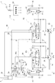
- the construction machine includes a hydraulic drive system 1 as shown in FIG. 1, and the hydraulic drive system 1 supplies hydraulic oil to each actuator to operate them.
- the configuration of the hydraulic drive system 1 included in the hydraulic excavator which is an example of the construction machine, will be described in detail.
- the hydraulic drive system 1 includes, in addition to the boom cylinder 2 and an arm cylinder for moving an arm, a bucket cylinder for moving a bucket, a swing motor for moving a swing body to which a boom is attached, and a travel for moving a traveling device. It is connected to various actuators such as a motor for driving and supplies hydraulic oil to them to operate various actuators.
- actuators other than the boom actuator that is, the boom cylinder 2 particularly related to the hydraulic drive system 1 of the first embodiment are not shown, and detailed description thereof will be omitted below. ..
- the hydraulic drive system 1 has first and second hydraulic pumps 11 and 12, and a hydraulic pressure supply device 13.
- the two hydraulic pumps 11 and 12 are, for example, tandem type double pumps, and are configured to be driven by a shared input shaft 14.
- the two hydraulic pumps 11 and 12 do not necessarily have to be tandem type double pumps, but may be parallel type double pumps, or may be single pumps each formed separately.
- the input shaft 14 is connected to a drive source 15 such as an engine or an electric motor, and when the drive source 15 rotates the input shaft 14, pressure oil is discharged from the two hydraulic pumps 11 and 12.
- the two hydraulic pumps 11 and 12 thus configured are so-called variable displacement type swash plate pumps.
- the two hydraulic pumps 11 and 12 have swash plates 11a and 12a, respectively, and the discharge capacity can be changed by changing the tilt angle of the swash plates 11a and 12a.
- the swash plates 11a and 12a are respectively provided with tilt angle adjusting mechanisms (not shown), and the tilt angles of the swash plates 11a and 12a can be changed by the tilt angle adjusting mechanisms.
- the two hydraulic pumps 11 and 12 having such a function are connected to a plurality of actuators including the boom cylinder 2 via a hydraulic pressure supply device 13, and hydraulic oil is supplied to each actuator via the hydraulic pressure supply device 13.
- the hydraulic pressure supply device 13 can change the direction of the hydraulic oil supplied to each actuator and can change the flow rate of the hydraulic oil supplied. That is, the driving direction of each actuator can be switched by changing the direction of the hydraulic oil, and the driving speed of the actuator can be changed by changing the flow rate of the hydraulic oil.
- the hydraulic pressure supply device 13 has a directional control valve corresponding to each actuator, and the hydraulic oil is caused to flow to the corresponding actuator by operating the corresponding directional control valve.
- the hydraulic pressure supply device 13 includes the first and second boom direction control valves 21, 22 and a pair of traveling direction control valves (not shown), a turning direction control valve, an arm direction control valve, and a bucket direction control valve. It has various directional control valves such as control valves. These directional control valves correspond to either of the two hydraulic pumps 11 and 12, and are connected in parallel to the corresponding hydraulic pumps 11 and 12.
- one traveling directional control valve, the first boom directional control valve 21, the bucket directional control valve, and the like are connected to the first hydraulic pump 11 in parallel via the first main passage 23, and
- the other hydraulic directional control valve, the second boom directional control valve 22, the turning directional control valve, and the arm directional control valve are connected to the two hydraulic pumps 12 in parallel via the second main passage 24.
- the boom direction control valves 21 and 22 correspond to the boom cylinder 2.
- the traveling direction control valves are a traveling device, the swing direction control valves are swing motors, the arm direction control valves are arm cylinders, and the bucket direction.
- the control valve is connected to each hydraulic pump 11, 12 in correspondence with the bucket cylinder.
- the hydraulic pumps 11 and 12 are connected to the first and second bypass passages 25 and 26, respectively, and the hydraulic oil discharged from the hydraulic pumps 11 and 12 is stored in the tanks via the bypass passages 25 and 26. It is discharged to 27. Further, one traveling directional control valve, the first boom directional control valve 21, the bucket directional control valve, and the like are connected in series to the first bypass passage 25, and these directional control valves operate. Then, the first bypass passage 25 is closed and the working oil is supplied to the actuator corresponding to the directional control valve. On the other hand, to the second bypass passage 26, the other traveling directional control valve, the second boom directional control valve 22, the turning directional control valve, the arm directional control valve, etc. are connected in series, and they are connected.
- the second bypass passage 26 is closed and hydraulic oil is supplied to the actuator corresponding to the directional control valve.
- These directional control valves operate in response to the operation of an operating device (not shown for the boom directional control valves 21 and 22 in FIG. 1 ), and have an opening area corresponding to the operation amount of the hydraulic pump 11, The oil supply from 12 to the actuator is adjusted, that is, the corresponding actuator is operated at the driving speed corresponding to the operation amount.
- the directional control valves for operating the boom that is, the directional control valves 21 and 22 for the first and second booms, which are particularly related to the hydraulic drive system 1 of the first embodiment, will be described in detail.
- the first and second boom direction control valves 21 and 22 are valves for controlling the operation of the boom cylinder 2, and are connected to the first and second hydraulic pumps 11 and 12, respectively, as described above. That is, the first boom directional control valve 21, which is an example of the first control valve, is connected to the first hydraulic pump 11 via the first main passage 23 and the first bypass passage 25. Further, the first boom directional control valve 21 is connected to the boom cylinder 2 and the tank 27, and by switching the connection state thereof, the direction in which the hydraulic oil flows is switched to expand and contract the boom cylinder 2.
- the boom cylinder 2 which is an example of the first actuator, is a double-acting cylinder and has two ports 2a and 2b. That is, the boom cylinder 2 extends when hydraulic oil is supplied to the head side port 2a (first port) which is one port and hydraulic oil is discharged from the rod side port 2b (second port) which is the other port. To do. On the other hand, the boom cylinder 2 retracts by discharging the hydraulic oil from the head side port 2a.
- the respective ports 2a and 2b are connected to the first boom direction control valve 21 via the head side passage 28 and the rod side passage 29, respectively, and the first boom direction control valve 21 is connected.
- the control valve 21 switches the connection destinations of the two passages 28 and 29 to extend and retract the boom cylinder 2.
- the first boom directional control valve 21 having such a function is a three-function directional control valve and has a spool 21a.
- the spool 21a can move from the neutral position M1 to the first offset position R1 and the second offset position L1, respectively, and in the state of being located at the neutral position M1, the two passages 28 and 29, the first main passage 23, and the tank. Shut off everything between 27 and.
- the first bypass passage 25 is open, and accordingly, the hydraulic oil from the first hydraulic pump 11 passes through the first bypass passage 25 and is located downstream of the first boom directional control valve 21 (that is, for the bucket). To the other directional control valve such as the directional control valve).
- the spool 21a moves to the first offset position R1, the head side passage 28 is connected to the first main passage 23 and the rod side passage 29 is connected to the tank 27.
- the working oil is supplied to the head side port 2a, the working oil is discharged from the rod side port 2b, and the boom cylinder 2 extends.
- the spool 21a moves to the second offset position L1
- the head side passage 28 and the tank 27 are shut off, and the rod side passage 29 is connected to the first main passage 23.
- hydraulic oil is supplied to the rod side port 2b, and the boom cylinder 2 can be retracted.
- the first bypass passage 25 is closed at each of the offset positions R1 and L1, and the hydraulic oil from the first hydraulic pump 11 is prevented from being guided to the tank 27 through the first bypass passage 25.
- hydraulic oil can be supplied to the boom cylinder 2.
- the first boom directional control valve 21 and the second boom directional control valve 22 cooperate with each other to expand and contract the boom cylinder 2, and thus the second boom directional control valve 22. Is configured as follows.
- the second boom directional control valve 22 that is an example of the second control valve is a valve that expands and contracts the boom cylinder 2 in cooperation with the first boom directional control valve 21, as described above. It is connected to the second hydraulic pump 12 via the passage 24 and the second bypass passage 26.
- the second boom directional control valve 22 is connected to the head side port 2a of the boom cylinder 2 via the lock valve 32, and is also connected to the tank 27, and the second main passage 24 and the head side port 2a.
- the boom cylinder 2 is extended by switching the connection state with and the opening and closing of the second bypass passage 26 to switch the flow direction of the hydraulic oil.
- the second boom directional control valve 22 is connected to the head-side port 2a via the confluence passage 30. That is, the merging passage 30 is connected to the head-side passage 28, and the second boom directional control valve 22 is connected to the head-side port 2 a via the merging passage 30 and the head-side passage 28.
- a check valve 31 is provided in the head-side passage 28 so that the hydraulic oil guided through the merging passage 30 does not flow backward toward the first boom directional control valve 21. That is, the check valve 31 allows the flow of hydraulic oil from the first boom directional control valve 21 toward the head side port 2a, and allows the hydraulic oil to flow from the head side port 2a toward the second boom directional control valve 22. Stop the flow.
- the second boom directional control valve 22 configured as described above is configured to switch the connection state between the merging passage 30 and the second main passage 24, and by connecting them, the second hydraulic pump 12 is connected. It is possible to combine the hydraulic oil of (1) with the hydraulic oil from the first hydraulic pump 11 and supply the hydraulic oil to the head side port 2a.
- the second boom directional control valve 22 having such a function is also a three-function directional control valve, and has a spool 22a.
- the spool 22a can move between the neutral position M2 and the first offset position R2 and the second offset position L2, and when the spool 22a is located at the neutral position M2, it blocks the merging passage 30 and the second main passage 24.
- the second bypass passage 26 is open, and the hydraulic fluid from the second hydraulic pump 12 passes through the second bypass passage 26 and is located downstream of the second boom directional control valve 22 (that is, the turning directional control valve 22 ). And other directional control valves such as arm control valves).
- the merging passage 30 is connected to the second main passage 24, and the working oil of the second hydraulic pump 12 passes through the merging passage 30 and the lock valve 32 to the head side passage 28.
- the hydraulic oil of the second hydraulic pump 12 can be merged with the hydraulic oil of the first hydraulic pump 11 in the head side passage 28, and a large amount of hydraulic oil can be guided to the head side port 2a. That is, in the hydraulic pressure supply device 13, when raising the boom, the hydraulic oils of the two hydraulic pumps 11 and 12 can be combined and guided to the boom cylinder 2.
- the spool 22a moves to the second offset position L2
- the head side passage 28 is connected to the tank 27 via the lock valve 32.
- the hydraulic oil in the head side port 2a can be discharged, and the boom cylinder 2 can be retracted.
- the second bypass passage 26 is closed at each of the offset positions R2, L2, and the hydraulic oil from the second hydraulic pump 12 is prevented from being guided to the tank 27 through the second bypass passage 26. As a result, hydraulic oil can be supplied to the boom cylinder 2.
- the two boom direction control valves 21 and 22 configured in this manner are configured as pilot type spool valves, and the spools 21a and 22a move by receiving the pilot pressures P1 to P4, respectively. That is, the first pilot pressure P1 and the second pilot pressure P2 act on each end of the spool 21a so as to oppose each other, and the spool 21a responds to the differential pressure P1-P2 of these two pilot pressures. Move to the position. For example, when the first pilot pressure P1 is greater than the second pilot pressure P2, the spool 21a moves to the first offset position R1, and when the second pilot pressure P2 is greater than the first pilot pressure P1, the spool 21a has the second offset pressure. Move to position L1.
- the spool 21a is provided with a pair of spring members 21b and 21c, and each of the spring members 21b and 21c exerts a biasing force against the first pilot pressure P1 and the second pilot pressure P2, respectively. It is given to the spool 21a. Therefore, the spool 21a is maintained at the neutral position M1 by the pair of spring members 21b and 21c, and the absolute value of the pressure difference
- the passages 23, 25, 28, 29 and the tank 27 are connected at an opening degree according to the differential pressure P1-P2.
- the opening degree between the head side passage 28 and the main passage 23 is controlled by the opening degree according to the differential pressure P1-P2, so that the hydraulic oil flowing to the head side port 2a is controlled.
- the flow rate can be adjusted (ie meter-in control).
- the third pilot pressure P3 and the fourth pilot pressure P4 act on each end of the spool 22a of the second boom directional control valve 22 so as to oppose each other.
- the spool 22a moves toward the first offset position R2
- the fourth pilot pressure P4 is higher than the third pilot pressure P3
- the spool 22a moves to the second position. Move in the offset position L2 direction.
- the spool 22a is provided with a pair of spring members 22b and 22c, and each of the spring members 22b and 22c exerts a biasing force against the third pilot pressure P3 and the fourth pilot pressure P4. Is given to the spool 22a. Therefore, the spool 22a is maintained at the neutral position by the pair of spring members 22b and 22c, and the absolute value of the differential pressure
- the openings of the passages 23 to 26, 28, 29, 30 and the tank 27 connected to each other are set to the pilot pressures P1 to P4 applied to the spools 21a and 22a, respectively. Controlled accordingly.
- the first boom directional control valve 21 thus configured is connected to the first and second electromagnetic proportional control valves 41 and 42 for applying pilot pressures P1 and P2 to the spool 21a thereof, and also for the second boom.
- Third and fourth electromagnetic proportional control valves 43 and 44 are connected to the directional control valve 22 to apply pilot pressures P3 and P4 to the spool 22a.
- the first to fourth electromagnetic proportional control valves 41 to 44 are connected to the pilot pump 16 (for example, a gear pump), reduce the pressure of pilot oil discharged from the pilot pump 16, and output it to the corresponding spools 21a and 22a. .. That is, the first pilot pressure P1 is output from the first electromagnetic proportional control valve 41 and is applied to one end of the spool 21a. Further, the second electromagnetic proportional control valve 42 outputs the second pilot pressure P2, which is applied to the other end of the spool 21a. Further, the third electromagnetic proportional control valve 43 outputs a third pilot pressure P3, which is applied to one end of the spool 22a.
- the pilot pump 16 for example, a gear pump
- the electromagnetic proportional control valve 44 outputs the fourth pilot pressure P4, which is applied to the other end of the spool 22a.
- the electromagnetic proportional control valves 41 to 44 are direct proportional type electromagnetic proportional valves, and output pilot pressures P1 to P4 of pressures corresponding to signals (for example, current or voltage) input to each.
- Each of the electromagnetic proportional control valves 41 to 44 thus configured is connected to the control device 50 to control their operation.
- the control device 50 outputs a signal to each of the electromagnetic proportional control valves 41 to 44 to control the operation of each of the electromagnetic proportional control valves 41 to 44.
- a boom operating device 51 is electrically connected to the control device 50.
- the boom operation device 51 which is an example of the operation device, is an electric joystick or a hydraulic operation valve, for example, and is a device for operating the boom.
- a pressure sensor for detecting the operating pressure is provided, and an electric signal according to the operation amount is output to the control device. More specifically, the boom operation device 51 has an operation lever 51a, and the operation lever 51a is configured to be tiltable in one and the other predetermined tilt directions.
- the boom operating device 51 outputs a signal corresponding to the tilting direction and the tilting amount of the operating lever 51 a to the control device 50, and the control device 50 responds to each electromagnetic signal according to the signal input from the boom operating device 51. Output to the proportional control valves 41 to 44.
- the control device 50 causes the boom operating device 51 to output a signal based on a signal output from the boom operating device 51.
- the first and second rising signals having a value (that is, a current value or a voltage value) corresponding to the tilt amount are output to the first electromagnetic proportional control valve 41 and the third electromagnetic proportional control valve 43, respectively.
- the pilot pressures P1 and P3 are output from the first and third electromagnetic proportional control valves 41 and 43, respectively, and the two hydraulic pumps 11 and 12 are output via the first and second boom directional control valves 21 and 22. Is guided to the head side port 2a.
- the boom cylinder 2 extends and the boom rises.
- the control device 50 responds to the tilted amount based on the signal output from the boom operating device 51.
- the first and second descending signals having different values that is, current value or voltage value
- the pilot pressures P2 and P4 are output from the second and fourth electromagnetic proportional control valves 42 and 44, respectively.
- the hydraulic oil of the first hydraulic pump 11 is supplied to the rod side port 2b via the first boom direction control valve 21 and the hydraulic oil of the head side port 2a via the second boom direction control valve 22. Is discharged to the tank 27. As a result, the boom cylinder 2 can be retracted to lower the boom.
- the hydraulic pressure supply device 13 configured as described above further includes a lock valve 32 for holding the boom in that position.
- the lock valve 32 is interposed in the merging passage 30 and can open and close the merging passage 30. More specifically, the lock valve 32 has a plunger 32a and a spring member 32b.
- the plunger 32a closes the merging passage 30 by moving to a closed position where it is seated on the valve seat 32c, and opens the merging passage 30 by moving to an open position away from the valve seat 32c.
- a spring member 32b is provided on the plunger 32a that moves in this manner, and the spring member 32b urges the plunger 32a in a direction in which it is seated on the valve seat 32c, that is, in a closing direction. Further, the following pressure acts on the plunger 32a so as to resist the biasing force of the spring member 32b.
- the lock valve 32 is interposed in the merging passage 30 as described above, and the merging passage 30 includes the port side portion 30a located on the head side port 2a side of the lock valve 32 and the lock valve 32 for the second boom. It is composed of a valve side portion 30b located on the direction control valve 22 side.
- the plunger 32a receives the hydraulic pressure of the port side portion 30a and the valve side portion 30b in a direction against the biasing force of the spring member 32b, that is, in the opening direction in which the plunger 32a is separated from the valve seat 32c.
- a pilot chamber (spring chamber) 32d is formed in the lock valve 32, and the plunger 32a has a direction in which the hydraulic pressure of the pilot chamber 32d is opposed to the hydraulic pressure of the port side portion 30a and the valve side portion 30b, that is, the closing direction. Have received.
- a selection valve 33 is connected to the pilot chamber 32d of the lock valve 32.
- the selection valve 33 is a two-function directional switching valve and has a spool 33a.
- the spool 33a moves between the neutral position M3 and the offset position L3.
- the spool 33a connects the pilot chamber 32d of the lock valve 32 to the port-side portion 30a of the merging passage 30 while being positioned at the neutral position M3.
- the merge passage 30 is closed by the plunger 32a.
- the pilot chamber 32d is connected to the tank 27, and the hydraulic pressure in the pilot chamber 32d becomes the tank pressure.
- the force for pushing the plunger 32a in the closing direction becomes larger than the force for pushing the plunger 32a in the closing direction, and the plunger 32a moves in the opening direction to open the merging passage 30.
- the merging passage 30 can be opened and closed by moving the spool 33a and switching the hydraulic pressure of the pilot chamber 32d.
- a spring member 33b is provided on the spool 33a of the selection valve 33 having such a function, and is biased to the neutral position M3 by the spring member 33b.
- the second pilot pressure P2 acts on the spool 33a so as to resist the biasing force of the spring member 33b, and the second pilot pressure P2 equal to or higher than a predetermined release pressure Pb determined by the biasing force of the spring member 33b. Acting on the spool 33a causes the spool 33a to move from the neutral position M3 to the offset position L3.
- a second electromagnetic proportional control valve 42 is connected to the spool 33a configured as described above so as to apply the second pilot pressure P2 thereto.
- the spool 21a of the first boom directional control valve 21 is connected to the second electromagnetic proportional control valve 42 that is also the fifth electromagnetic proportional control valve.
- the spool 33a of the selection valve 33 is the first spool 33a.
- the boom directional control valve 21 is connected in parallel. That is, when the second down signal which is also the third down signal is input, the second solenoid proportional control valve 42 outputs the second pilot pressure P2 (corresponding to the fifth pilot pressure) to the spool 33a in addition to the spool 21a. To do.
- the third pilot pressure is output from the third electromagnetic proportional control valve 43.
- the spool 22a of the second boom directional control valve 22 moves to the first offset position R2.
- the valve side portion 30b of the merging passage 30 is connected to the second main passage 24, and the hydraulic fluid from the second hydraulic pump 12 is guided to the valve side portion 30b.
- the hydraulic pressure guided to the pilot chamber 32d of the lock valve 32 is smaller than the hydraulic pressure of the port side portion 30a by the amount of pressure drop when passing the outside of the plunger 32a, so that the passage 30 opens.
- the flow of hydraulic oil from the first boom directional control valve 21 to the head-side port 2a is allowed, and even if the lock valve 32 is interposed in the head-side passage 28, the hydraulic oil of the two hydraulic pumps 11 and 12 may be inserted. Can be merged and led to the head-side port 2a. That is, the boom cylinder 2 can be extended to raise the boom.
- the operation lever 51a when the operation lever 51a is not operated, the second down signal is not output from the control device 50, and the second pilot pressure P2 becomes substantially zero. Therefore, the spool 33a of the selection valve 33 is maintained at the neutral position M3, and the hydraulic pressure of the port side portion 30a is guided to the pilot chamber 32d of the lock valve 32. Then, the plunger 32a moves to the closed position and the merging passage 30 is closed. Since the head side passage 28 is also closed by the check valve 31, the head side port 2a and the first and second boom direction control valves 21, 22 are completely shut off, and the head side port 2a is operated. Oil cannot be discharged. Therefore, when the operation lever 51a is not operated, the boom can be held at that position.
- the operation lever 51a when the operation lever 51a is not operated, as described above, the second lowering signal is not output from the control device 50, so that the state in which the merging passage 30 is closed is maintained. Therefore, when the operation lever 51a is not operated, the secondary pressure is intended when the valve body of the fourth electromagnetic proportional control valve 44 sticks in a state where the primary side and the secondary side communicate with each other or the electric system malfunctions. Even if it occurs without it, the hydraulic oil in the head side port 2a is not discharged. That is, the boom can be held at that position, and the boom can be prevented from unintentionally descending due to its own weight.
- the fail safe when the valve body sticks in a state where the primary side and the secondary side communicate with each other, the fail safe is achieved as follows. That is, in the head-side passage 28, the check valve 31 blocks the flow in the direction of returning to the tank 27. Further, although the lock valve 32 of the merging passage 30 is released, the spool 22a of the second boom directional control valve 22 is located at the neutral position M2. Is cut off. Therefore, in the fourth electromagnetic proportional control valve 42, fail-safe can be achieved even when the valve body sticks in a state where the primary side and the secondary side communicate with each other.
- the second lowering signal is input to the second electromagnetic proportional control valve 42, and the second electromagnetic proportional control valve 42 moves the spool 33a of the selection valve 33 to the first position.
- 2 Pilot pressure P2 is output.
- the spool 33a moves to the offset position L3, and accordingly, the pilot chamber 32d of the lock valve 32 communicates with the tank 27.
- the hydraulic drive system 1 In the hydraulic drive system 1 according to the present embodiment, the case where the hydraulic drive system 1 is applied to the hydraulic excavator has been described, but the application target is not limited to the hydraulic excavator. That is, the hydraulic drive system 1 may be applied to construction machines such as hydraulic cranes and wheel loaders, and construction vehicles such as forklifts. Further, in the hydraulic drive system 1 of the present embodiment, the object to be moved up and down is the boom, but it is not limited to the boom and may be an arm or a hook of a hoisting machine. In these cases, the actuators are arm cylinders and hoisting motors.
- the electromagnetic proportional control valve that applies the pilot pressure to the spool 33a of the selection valve 33 is shared with the second electromagnetic proportional control valve 42, but it is not always necessary to share them. Apart from this, it may be newly provided.
- the first to fourth electromagnetic proportional control valves 41 to 44 are formed separately from the first and second boom directional control valves 21 and 22, but this is not always necessary. Need not be formed as. That is, the first to fourth electromagnetic proportional control valves 41 to 44 may be configured integrally with the first and second boom direction control valves 21 and 22, and the form thereof does not matter.
Landscapes
- Engineering & Computer Science (AREA)
- General Engineering & Computer Science (AREA)
- Fluid Mechanics (AREA)
- Physics & Mathematics (AREA)
- Mechanical Engineering (AREA)
- Civil Engineering (AREA)
- Structural Engineering (AREA)
- Mining & Mineral Resources (AREA)
- Chemical & Material Sciences (AREA)
- Analytical Chemistry (AREA)
- Fluid-Pressure Circuits (AREA)
- Operation Control Of Excavators (AREA)
- Component Parts Of Construction Machinery (AREA)
Abstract
Priority Applications (3)
| Application Number | Priority Date | Filing Date | Title |
|---|---|---|---|
| CN201980049811.1A CN112424484B9 (zh) | 2019-01-11 | 2019-12-10 | 油压驱动系统 |
| US17/288,339 US11668330B2 (en) | 2019-01-11 | 2019-12-10 | Hydraulic drive system |
| GB2106782.2A GB2593340B (en) | 2019-01-11 | 2019-12-10 | Hydraulic drive system |
Applications Claiming Priority (2)
| Application Number | Priority Date | Filing Date | Title |
|---|---|---|---|
| JP2019-003451 | 2019-01-11 | ||
| JP2019003451A JP7245055B2 (ja) | 2019-01-11 | 2019-01-11 | 油圧駆動システム |
Publications (1)
| Publication Number | Publication Date |
|---|---|
| WO2020145006A1 true WO2020145006A1 (fr) | 2020-07-16 |
Family
ID=71521107
Family Applications (1)
| Application Number | Title | Priority Date | Filing Date |
|---|---|---|---|
| PCT/JP2019/048358 WO2020145006A1 (fr) | 2019-01-11 | 2019-12-10 | Système d'entraînement hydraulique |
Country Status (5)
| Country | Link |
|---|---|
| US (1) | US11668330B2 (fr) |
| JP (1) | JP7245055B2 (fr) |
| CN (1) | CN112424484B9 (fr) |
| GB (1) | GB2593340B (fr) |
| WO (1) | WO2020145006A1 (fr) |
Families Citing this family (1)
| Publication number | Priority date | Publication date | Assignee | Title |
|---|---|---|---|---|
| KR102263246B1 (ko) * | 2020-11-27 | 2021-06-10 | 주식회사 대진에이치에스 | 로직밸브를 내포하는 세이프티 락 기능이 있는 굴삭기 붐/아암 비상 하강장치 |
Citations (2)
| Publication number | Priority date | Publication date | Assignee | Title |
|---|---|---|---|---|
| JP2010013855A (ja) * | 2008-07-03 | 2010-01-21 | Hitachi Constr Mach Co Ltd | 建設機械の油圧回路装置 |
| JP2018105333A (ja) * | 2016-12-22 | 2018-07-05 | 川崎重工業株式会社 | 油圧ショベル駆動システム |
Family Cites Families (7)
| Publication number | Priority date | Publication date | Assignee | Title |
|---|---|---|---|---|
| JP3170874B2 (ja) * | 1992-05-19 | 2001-05-28 | コベルコ建機株式会社 | 建設機械の油圧回路 |
| EP0753691A4 (fr) * | 1994-03-29 | 1997-10-22 | Komatsu Mfg Co Ltd | Vanne distributrice regulatrice commandee par pression de reference et dispositif de commande a cylindre |
| US6955115B1 (en) * | 1999-03-17 | 2005-10-18 | Caterpillar Inc. | Hydraulic circuit having pressure equalization during regeneration |
| EP1143151B1 (fr) * | 1999-10-20 | 2007-01-03 | Hitachi Construction Machinery Co., Ltd. | Appareil de vanne de commande a rupture de conduit |
| US10161108B2 (en) * | 2014-01-28 | 2018-12-25 | Hitachi Construction Machinery Co., Ltd. | Hydraulic fluid energy recovery system for work |
| JP5975073B2 (ja) * | 2014-07-30 | 2016-08-23 | コベルコ建機株式会社 | 建設機械 |
| JP6603568B2 (ja) | 2015-12-14 | 2019-11-06 | 川崎重工業株式会社 | 油圧駆動システム |
-
2019
- 2019-01-11 JP JP2019003451A patent/JP7245055B2/ja active Active
- 2019-12-10 US US17/288,339 patent/US11668330B2/en active Active
- 2019-12-10 WO PCT/JP2019/048358 patent/WO2020145006A1/fr active Application Filing
- 2019-12-10 CN CN201980049811.1A patent/CN112424484B9/zh active Active
- 2019-12-10 GB GB2106782.2A patent/GB2593340B/en active Active
Patent Citations (2)
| Publication number | Priority date | Publication date | Assignee | Title |
|---|---|---|---|---|
| JP2010013855A (ja) * | 2008-07-03 | 2010-01-21 | Hitachi Constr Mach Co Ltd | 建設機械の油圧回路装置 |
| JP2018105333A (ja) * | 2016-12-22 | 2018-07-05 | 川崎重工業株式会社 | 油圧ショベル駆動システム |
Also Published As
| Publication number | Publication date |
|---|---|
| US20210381532A1 (en) | 2021-12-09 |
| US11668330B2 (en) | 2023-06-06 |
| CN112424484B9 (zh) | 2023-06-23 |
| JP2020112210A (ja) | 2020-07-27 |
| CN112424484A (zh) | 2021-02-26 |
| GB2593340B (en) | 2023-11-22 |
| GB2593340A (en) | 2021-09-22 |
| CN112424484B (zh) | 2023-04-28 |
| JP7245055B2 (ja) | 2023-03-23 |
Similar Documents
| Publication | Publication Date | Title |
|---|---|---|
| US9080310B2 (en) | Closed-loop hydraulic system having regeneration configuration | |
| US9790659B2 (en) | Hydraulic shovel | |
| WO2014068973A1 (fr) | Dispositif de commande de pression hydraulique | |
| WO2017221758A1 (fr) | Système d'entraînement hydraulique | |
| JP2017226492A5 (fr) | ||
| CN110799710B (zh) | 用于工程机械的动臂控制系统 | |
| CN112352110B (zh) | 油压驱动系统 | |
| US11466426B2 (en) | Material moving machines and pilot hydraulic switching systems for use therein | |
| JPWO2018021288A1 (ja) | ショベル、ショベル用コントロールバルブ | |
| US11927205B2 (en) | Hydraulic system | |
| CN110352303B (zh) | 工程机械的驱动装置 | |
| WO2020145006A1 (fr) | Système d'entraînement hydraulique | |
| JP4933299B2 (ja) | 建設機械の油圧制御装置 | |
| KR102667937B1 (ko) | 작업 차량 | |
| JP2005140153A (ja) | 建設機械の油圧制御装置 | |
| WO2023176732A1 (fr) | Dispositif d'entraînement hydraulique | |
| JP6682396B2 (ja) | ショベル | |
| JP2022189137A (ja) | 制御弁装置、及びそれを備える油圧駆動システム | |
| JP2023135535A (ja) | 液圧駆動装置 | |
| JP2023050680A (ja) | 作業機械における油圧制御システム | |
| CN116623743A (zh) | 液压控制系统及作业机械 |
Legal Events
| Date | Code | Title | Description |
|---|---|---|---|
| 121 | Ep: the epo has been informed by wipo that ep was designated in this application |
Ref document number: 19908625 Country of ref document: EP Kind code of ref document: A1 |
|
| ENP | Entry into the national phase |
Ref document number: 202106782 Country of ref document: GB Kind code of ref document: A Free format text: PCT FILING DATE = 20191210 |
|
| NENP | Non-entry into the national phase |
Ref country code: DE |
|
| 122 | Ep: pct application non-entry in european phase |
Ref document number: 19908625 Country of ref document: EP Kind code of ref document: A1 |