WO2020144958A1 - 燃料噴射弁を制御する制御装置及びプログラム - Google Patents
燃料噴射弁を制御する制御装置及びプログラム Download PDFInfo
- Publication number
- WO2020144958A1 WO2020144958A1 PCT/JP2019/046279 JP2019046279W WO2020144958A1 WO 2020144958 A1 WO2020144958 A1 WO 2020144958A1 JP 2019046279 W JP2019046279 W JP 2019046279W WO 2020144958 A1 WO2020144958 A1 WO 2020144958A1
- Authority
- WO
- WIPO (PCT)
- Prior art keywords
- fuel injection
- valve
- coil
- initial position
- drive
- Prior art date
- Legal status (The legal status is an assumption and is not a legal conclusion. Google has not performed a legal analysis and makes no representation as to the accuracy of the status listed.)
- Ceased
Links
Images




Classifications
-
- F—MECHANICAL ENGINEERING; LIGHTING; HEATING; WEAPONS; BLASTING
- F02—COMBUSTION ENGINES; HOT-GAS OR COMBUSTION-PRODUCT ENGINE PLANTS
- F02D—CONTROLLING COMBUSTION ENGINES
- F02D41/00—Electrical control of supply of combustible mixture or its constituents
- F02D41/20—Output circuits, e.g. for controlling currents in command coils
-
- F—MECHANICAL ENGINEERING; LIGHTING; HEATING; WEAPONS; BLASTING
- F02—COMBUSTION ENGINES; HOT-GAS OR COMBUSTION-PRODUCT ENGINE PLANTS
- F02D—CONTROLLING COMBUSTION ENGINES
- F02D41/00—Electrical control of supply of combustible mixture or its constituents
- F02D41/30—Controlling fuel injection
- F02D41/32—Controlling fuel injection of the low pressure type
- F02D41/34—Controlling fuel injection of the low pressure type with means for controlling injection timing or duration
-
- F—MECHANICAL ENGINEERING; LIGHTING; HEATING; WEAPONS; BLASTING
- F02—COMBUSTION ENGINES; HOT-GAS OR COMBUSTION-PRODUCT ENGINE PLANTS
- F02M—SUPPLYING COMBUSTION ENGINES IN GENERAL WITH COMBUSTIBLE MIXTURES OR CONSTITUENTS THEREOF
- F02M51/00—Fuel-injection apparatus characterised by being operated electrically
- F02M51/06—Injectors peculiar thereto with means directly operating the valve needle
- F02M51/08—Injectors peculiar thereto with means directly operating the valve needle specially for low-pressure fuel-injection
-
- F—MECHANICAL ENGINEERING; LIGHTING; HEATING; WEAPONS; BLASTING
- F02—COMBUSTION ENGINES; HOT-GAS OR COMBUSTION-PRODUCT ENGINE PLANTS
- F02M—SUPPLYING COMBUSTION ENGINES IN GENERAL WITH COMBUSTIBLE MIXTURES OR CONSTITUENTS THEREOF
- F02M61/00—Fuel-injectors not provided for in groups F02M39/00 - F02M57/00 or F02M67/00
- F02M61/04—Fuel-injectors not provided for in groups F02M39/00 - F02M57/00 or F02M67/00 having valves, e.g. having a plurality of valves in series
- F02M61/10—Other injectors with elongated valve bodies, i.e. of needle-valve type
-
- Y—GENERAL TAGGING OF NEW TECHNOLOGICAL DEVELOPMENTS; GENERAL TAGGING OF CROSS-SECTIONAL TECHNOLOGIES SPANNING OVER SEVERAL SECTIONS OF THE IPC; TECHNICAL SUBJECTS COVERED BY FORMER USPC CROSS-REFERENCE ART COLLECTIONS [XRACs] AND DIGESTS
- Y02—TECHNOLOGIES OR APPLICATIONS FOR MITIGATION OR ADAPTATION AGAINST CLIMATE CHANGE
- Y02T—CLIMATE CHANGE MITIGATION TECHNOLOGIES RELATED TO TRANSPORTATION
- Y02T10/00—Road transport of goods or passengers
- Y02T10/10—Internal combustion engine [ICE] based vehicles
- Y02T10/40—Engine management systems
Definitions
- the present invention relates to a control device and a program for controlling a fuel injection valve.
- a control device for an internal combustion engine when controlling a multi-stage injection (also referred to as “split injection”) of a fuel injection valve, a control device for an internal combustion engine is capable of performing the next fuel injection by the fuel injection valve after performing the fuel injection.
- the injection interval time interval
- This is to return the mover and the valve element of the fuel injection valve to the state before the fuel injection.
- it is required to increase the number of injection stages in multi-stage injection, and if the injection interval is long, the demand for increasing the number of injection stages cannot be satisfied.
- an intermediate current is passed by applying a voltage that does not open the valve between the first fuel injection (first fuel injection) and the second fuel injection (second fuel injection).
- the voltage application for supplying this intermediate current starts before the valve body is closed by the previous fuel injection, and the current is applied by the fuel injection after the first time when the valve body is closed by the previous fuel injection.
- Half of the time up to the second time point at which the feeding is started is terminated before the first time point has elapsed.”
- an object of the present invention is to grasp the state of the mover of the fuel injection valve from the end of the previous injection to the start of the next injection.
- a control device for controlling a fuel injection valve closes and closes a fuel passage by abutting on a valve seat, and opens the fuel passage by moving away from the valve seat.
- the control device includes a control unit configured to perform intermediate energization in which the coil is energized by a switching operation when the valve body is in contact with the valve seat and the valve is closed.
- This control unit energizes the coil by switching operation when the movable unit is displaced in the direction away from the fixed unit after the valve body comes into contact with the valve seat and closes the valve.
- a process to detect the initial position return timing at which the movable part reaches the initial position after the valve body is closed is performed. To do.
- the state of the mover of the fuel injection valve (initial position return timing) can be detected from the end of the previous injection to the start of the next injection. For example, by supplying the drive current to the coil based on the detection result, the mover can be returned to the state before the injection at an early stage, and the injection interval of the fuel injection valve can be shortened.
- timing chart of undershoot reduction control It is an example of a timing chart of undershoot reduction control according to the first embodiment of the present invention. It is a flow chart which shows the example of a procedure of fuel injection control processing by the fuel injection control device concerning a 1st embodiment of the present invention. It is an example of a timing chart when performing the initial position return timing detection processing and the undershoot reduction control according to the second embodiment of the present invention in parallel. It is an example of a timing chart of the initial position return timing detection processing according to the third embodiment of the present invention. It is an example of a timing chart of undershoot reduction control according to a fourth embodiment of the present invention. It is an example of a timing chart of undershoot reduction control according to a fifth embodiment of the present invention. It is an example of a timing chart of undershoot reduction control according to a sixth embodiment of the present invention. It is a figure which shows the constructional example of the fuel injection valve provided with the intermediate stroke mechanism which concerns on the 7th Embodiment of this invention.
- a microcomputer that controls a fuel injection valve monitors the operating state of the fuel injection valve, detects at least the position of a mover that drives the valve element, and moves the mover so that the next injection can be performed early. Control the behavior of.
- a fuel injection control device mounted on the internal combustion engine system according to the first embodiment of the present invention will be described.
- the fuel injection control device is a control device that controls the fuel injection valve.
- FIG. 1 is a block diagram showing a configuration example of a fuel injection control device included in the internal combustion engine system according to the first embodiment.
- the fuel injection control device 101 shown in FIG. 1 is built in an ECU (Engine Control Unit) 320 as shown in FIG. 3 described later.
- the present embodiment is an example in which the fuel injection valve 100 is applied to a cylinder direct injection engine, but the usage mode of the fuel injection valve 100 is not limited to this example.
- the power source of a battery (not shown) is supplied to the fuel injection control device 101 provided in the ECU 320 via the fuse 108 and the relay 109.
- the fuel injection control device 101 calculates an appropriate energization time and injection start timing according to the operating state of the engine, and based on the power source of the battery, sends the coil of the fuel injection valve 100 (electromagnetic solenoid for opening the valve) 303.
- a drive current (excitation current) is supplied.
- the fuel injection control device 101 basically includes an engine state detection unit 103, a drive control unit 102 (an example of a control unit), a drive IC 104, a high voltage generation circuit 105, a fuel injection valve drive circuit (Hi) 106a, and a fuel injection.
- the valve drive circuit (Lo) 106b is provided.
- the engine state detection unit 103 collects various information such as the number of revolutions of an internal combustion engine (engine), the intake air amount, the cooling water temperature, the fuel pressure, the failure state of the internal combustion engine, and the like, and provides them to the drive control unit 102. ..
- the drive control unit 102 includes a fuel injection valve pulse width calculation unit 102a and a fuel injection valve drive waveform command unit 102b.
- the fuel injection valve pulse width calculation unit 102a based on various information (operating state of the internal combustion engine) obtained from the engine state detection unit 103, the pulse width of the fuel injection pulse that defines the fuel injection period of the fuel injection valve 100 (hereinafter referred to as “ It may be referred to as “ejection pulse width”) and outputs it to the drive IC 104.
- the fuel injection valve drive waveform command unit 102b calculates a command value (drive current waveform) of a drive current supplied to open the fuel injection valve 100 or maintain the valve open state, and outputs it to the drive IC 104. To do.
- the fuel injection valve drive waveform command unit 102b based on the calculation result of the fuel injection valve pulse width calculation unit 102a and the operating state of the internal combustion engine, the waveform (current profile) of the drive current supplied to the coil 303 of the fuel injection valve 100. Select.
- the high voltage generation circuit 105 uses the battery voltage VB (see FIG. 2) supplied from the battery to generate a high power supply voltage (hereinafter referred to as “high voltage”) required when the electromagnetic solenoid fuel injection valve 100 opens. VH).
- the high voltage generation circuit 105 boosts the battery voltage VB based on a command from the drive IC 104 so as to reach a desired target high voltage.
- the high voltage VH for ensuring the valve opening force of the valve body 301 (see FIG. 3) and the open state so that the valve body 301 does not close after opening. Therefore, two systems of the battery voltage VB for holding the battery are provided.
- Two fuel injection valve drive circuits 106a and 106b are provided on the upstream side and the downstream side of the fuel injection valve 100.
- the two fuel injection valve drive circuits 106a and 106b supply a drive current to the fuel injection valve 100. Supply.
- the details of the configuration of the fuel injection valve drive circuits 106a and 106b will be described later, and thus the description thereof is omitted here.
- the drive IC 104 based on the injection pulse width calculated by the fuel injection valve pulse width calculation unit 102a and the drive current waveform (current profile) calculated by the fuel injection valve drive waveform command unit 102b, the fuel injection valve drive circuit 106a. And a drive signal to the fuel injection valve drive circuit 106b.
- the drive IC 104 controls the fuel injection valve drive circuit 106a and the fuel injection valve drive circuit 106b to control the high voltage VH or the battery voltage VB applied to the coil 303 of the fuel injection valve 100. In this way, the drive IC 104 supplies a desired drive current to the coil 303 of the fuel injection valve 100, drives and controls the fuel injection of the fuel injection valve 100, and adjusts the fuel injection amount required for combustion of the internal combustion engine. Optimal control.
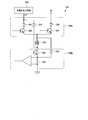
- FIG. 2 is a circuit diagram showing the fuel injection valve drive circuits 106a and 106b and their peripheral circuits.
- the fuel injection valve drive circuit 106a includes a switching element, and is connected between the high voltage generation circuit 105 and the coil 303 and between the relay 109 and the coil 303.
- the fuel injection valve drive circuit 106a supplies the fuel injection valve 100 with either a high power supply voltage (high voltage VH) generated by the high voltage generation circuit 105 or a low power supply voltage (battery voltage VB) that is a battery power supply. Then, the selected power supply voltage is supplied to the coil 303 of the fuel injection valve 100.
- high voltage VH high power supply voltage
- VB battery voltage
- a high voltage VH high voltage power supply
- a current (driving current) required for opening the valve to the coil 303 of the fuel injection valve 100 Energize.
- the power supply voltage is switched to the battery voltage VB (low power supply voltage), and a holding current (driving current) is passed through the coil 303 of the fuel injection valve 100.
- the fuel injection valve drive circuit 106a supplies the current necessary to open the fuel injection valve 100, and therefore the high voltage VH is supplied from the high voltage generation circuit 105 in the figure to the diode 201 provided for preventing current backflow. Is supplied to the fuel injection valve 100 via a circuit including the first transistor 203 in the figure.
- the transistor is an example of a switching element, and a bipolar transistor or a MOS transistor is used.
- the battery voltage VB required to maintain the opened state of the fuel injection valve 100 is changed to the diode 202 for preventing current backflow, as with the high voltage VH. Via the circuit including the second transistor 204 in the figure, to the fuel injection valve 100.
- the fuel injection valve drive circuit 106b is a drive circuit provided downstream of the fuel injection valve 100 for supplying (supplying) a drive current to the fuel injection valve 100.
- the fuel injection valve drive circuit 106b is provided with a third transistor 205. By turning on the third transistor 205, the power supplied from the fuel injection valve drive circuit 106a on the upstream side is supplied to the fuel injection valve. Can be applied to 100.
- the drive control unit 102 detects a current consumed in the fuel injection valve 100 by the shunt resistor 206, thereby performing desired current control of the fuel injection valve 100 described later.
- the fuel injection valve drive circuit 106a and the fuel injection valve drive circuit 106b will be referred to as the "fuel injection valve drive circuit 106" if they are not particularly distinguished or collectively referred to.
- a diode 209 is connected in the forward direction between the downstream side of the coil 303 and the high voltage generation circuit 105, and a diode 208 is connected in the forward direction between the shunt resistor 206 and the upstream side of the coil 303.
- the counter electromotive force generated in the coil 303 of the fuel injection valve 100 causes the diode 208 and the diode 209 to be energized.
- the current is fed back to the high voltage generation circuit 105 side, and the drive current supplied to the coil 303 is rapidly reduced.
- a reverse electromotive force (-VH) having a magnitude corresponding to the high voltage VH is generated between the terminals of the coil 303 as the counter electromotive force.
- the present embodiment shows an example of the driving method of the fuel injection valve 100.
- the battery is not the high voltage VH but the battery when the fuel injection valve 100 is opened.
- the voltage VB may be used.
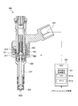
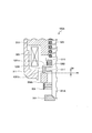
- FIG. 3 is a cross-sectional view showing a structural example of the fuel injection valve 100.
- the fuel injection valve 100 is an electromagnetic fuel injection device including a normally closed solenoid valve.
- the structure of the fuel injection valve 100 shown in FIG. 3 is an example, and it goes without saying that the structure is not limited to this example.
- the fuel injection valve 100 has a substantially rod-shaped valve body 301 inside, and an orifice cup having a valve seat 302 is provided at a position facing the lower end of the valve body 301.
- An injection hole 302h for injecting fuel is formed in the valve seat 302.
- a spring 309 that biases the valve body 301 in the valve closing direction (downward direction) is provided above the valve body 301.
- the fuel injection valve 100 includes a hollow housing 311 in which the valve body 301 is arranged.
- a fixed core 310 (an example of a fixed portion) is fixed to the inner surface of the housing 311, and a solenoid-shaped coil 303 is arranged inside the fuel injection valve 100 so as to go around the central axis of the fuel injection valve 100. Has been done.
- a vertically movable valve element 301 is arranged on the central axis of the fuel injection valve 100.
- a mover 306 (an example of a movable portion), which is a movable core, is arranged so as to go around the valve body 301.
- An annular magnetic path is formed in the fixed core 310, the mover 306, and the housing 311 so as to surround the coil 303.
- the space (fuel passage) inside the housing 311 is filled with fuel, and when a current flows through the coil 303, the mover 306 is attracted to the coil 303. Then, when the lower end of the valve body 301 separates from the valve seat 302, fuel is injected from the injection hole 302h (fuel passage outlet) opened in the housing 311 that was closed by the valve body 301 until then.
- a set spring 309 for pressing (biasing) the valve body 301 toward the valve seat 302 is arranged above the valve body 301. Further, below the mover 306, between the mover 306 and the housing 311, a zero spring 304 that urges the mover 306 in the valve opening direction is arranged.
- the mover 306 in the non-energized state after the fuel injection returns to the initial position Pi (zero displacement) due to the balance of the loads of the springs.
- a gap G1 is formed between the mover 306 and the fixed core 310.
- a rigid conductor 315 is fixed to the winding start end and the winding end end of the coil 303.
- the coil 303 and the ECU 320 are electrically connected via the conductor 315.
- the ECU 320 is an example of a microcomputer and includes the fuel injection control device 101. Further, the fuel injection control device 101 includes a CPU 101a and a memory 101b as an example.
- the CPU 101a is a processor that performs arithmetic processing.
- the memory 101b is a storage unit including a volatile or non-volatile semiconductor memory or the like.
- a computer program for controlling the fuel injection valve 100 may be stored in the memory 101b.
- the CPU 101a reads out and executes the computer program recorded in the memory 101b to realize all or part of the functions of the fuel injection control device 101.
- An ignition switch signal for instructing the start (ignition) of the internal combustion engine is input to the ECU 320. When detecting that the ignition switch signal is on, the CPU 101a starts the process of the computer program for fuel injection control.
- another arithmetic processing device such as an MPU (Micro Processing Unit) may be used instead of the CPU 101a.
- the control device (fuel injection control device 101) that controls the fuel injection valve 100 closes and closes the fuel passage by contacting the valve seat 302, and opens the fuel passage by moving away from the valve seat 302.
- Valve body 301 that opens by means of a valve
- a movable portion (movable element 306) that drives the valve body 301
- a coil 303 that generates a magnetic attraction force by flowing an electric current
- a fixed portion that attracts the movable portion by the magnetic attraction force.
- the control device (fuel injection control device 101) is configured to perform intermediate energization in which the coil 303 is energized by a switching operation when the valve body 301 abuts the valve seat 302 and is closed.
- the drive control unit 102) is provided.
- the movable portion (movable element 306). Is movable relative to the valve body 301, and is configured to return to the initial position when the movable portion is not energized to the coil 303.
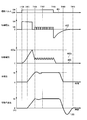
- FIG. 4 is an example of a timing chart showing the drive current, the mover displacement, and the valve displacement of the conventional fuel injection valve 100.
- a drive current profile 403 (drive current waveform) is preset based on the characteristics of the fuel injection valve 100, and fuel injection is performed according to this drive current profile 403.
- the injection amount characteristic of the valve 100 is recorded in the memory 101b in the ECU 320 (see FIG. 3).
- the fuel injection control device 101 drives the fuel injection valve 100 based on the operating state (intake air amount) of the internal combustion engine (not shown) and the injection amount characteristic of the fuel injection valve 100.
- the command time (injection pulse signal 401) is calculated.
- the injection pulse signal 401 is turned on from a desired injection start timing T404 calculated by the ECU 320, and the current control of the fuel injection valve 100 is performed based on the drive current profile 403 stored in the ECU 320 in advance.
- the drive current profile 403 in the example of FIG. 4 has a plurality of target current values (target current values) such as a valve opening peak current 403a for opening the fuel injection valve 100 and a first holding current 403b for holding the valve open. Composed of.
- the fuel injection control device 101 controls the operation of the fuel injection valve 100 by switching the target current value (valve opening peak current 403a, first holding current 403b) supplied to the coil 303 based on a preset control sequence. .. In this way, the fuel injection control device 101 continues to apply the drive current to the fuel injection valve 100 until the timing (T408) when the injection pulse signal 401 is turned off.
- the behavior of the valve body 301 of the conventional fuel injection valve 100 will be described with reference to FIGS. 3 and 4.
- the injection pulse signal 401 is turned ON (T404)
- the high voltage VH is applied to the coil 303 of the fuel injection valve 100 as the drive voltage 402 until the drive current supplied to the coil 303 reaches the valve opening peak current 403a. ..
- the magnetic attraction force of the coil 303 becomes larger than the spring force of the set spring 309.
- the mover 306 starts to move in the valve opening direction, and the valve element 301 separates from the valve seat 302 in the form of being pulled up by this, and the valve opening is started.
- valve opening force by the current behavior until the drive current of the coil 303 reaches the valve opening peak current 403a is continued, so that the valve body 301 continues the valve opening operation and the mover 306 moves to the fixed core 310.
- the position St is reached (T406).
- the valve body 301 performs a bouncing operation for a while, and then enters a stable valve opening state (T407).
- the battery voltage VB that holds the valve open state so that the valve body 301 does not close is applied to the coil 303.
- the state in which the valve body 301 is completely opened is maintained until the injection pulse signal 401 is turned off (T408), and then the residual magnetic field of the fuel injection valve 100 decreases.
- the mover 306 that has lost the magnetic attraction force is pushed back by the load (spring force) of the set spring 309 and the force due to the fuel pressure to the valve body 301 and the valve closed position where the valve body 301 contacts the valve seat 302. ,
- the valve body 301 is completely closed (T409).
- the force of the set spring 309 acting on the valve body 301 is transmitted to the mover 306 via the collision surface of the valve body 301 and the collision surface of the mover 306.
- the collision surface of the mover 306 separates from the collision surface of the valve body 301 and continues the movement in the valve closing direction (direction away from the fixed core 310). ..
- a force that pushes back the moving element 306 in the valve opening direction is applied by the zero spring 304, and at time T410, the collision surface of the movable element 306 contacts the collision surface of the valve element 301.
- the mover 306 is maintained at zero displacement, that is, the initial position Pi.
- the operation of the mover 306 leaving the valve body 301 and coming into contact with the collision surface of the valve body 301 again during the valve closing operation is called “undershoot”. While the undershoot US is generated in the mover 306, the fuel injection valve 100 cannot inject fuel. This is because the collision surface of the mover 306 is not in contact with the collision surface of the valve body 301, so the force for moving the valve body 301 in the valve opening direction becomes unstable depending on the position of the mover 306, and as a result, This is because the fuel injection amount varies. Therefore, it is necessary to quickly stop (return) the mover 306 to the initial position Pi to shorten the time during which the undershoot US occurs.
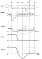
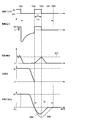
- FIG. 5 is an example of a timing chart of the initial position return timing detection process according to the first embodiment.
- FIG. 5 shows the relationship among the injection pulse signal, the drive voltage and drive current supplied to the fuel injection valve 100, and the behavior of the valve body 301 and the mover 306. The behavior of the mover 306 after the injection pulse signal is turned off will be described below.
- the fuel injection valve drive circuit 106 sets the drive voltage applied to the coil 303 to 0 V or less and reduces the drive current.
- the mover 306 starts moving in the valve closing direction together with the valve body 301.
- the injection pulse signal is turned on again, and the fuel injection valve drive circuit 106a applies the battery voltage VB to the coil 303 (the period from T502 to T506). Then, the fuel injection valve drive circuit 106a (second transistor 203) performs the switching operation so that the predetermined target current value 507 is achieved.
- the period Tc0 of T501 to T506 corresponds to the conventional injection interval period.
- the collision surface of the mover 306 separates from the collision surface of the valve seat 302. Then, the mover 306 moves in a direction away from the fixed core 310 while receiving the load of the zero spring 304. Then, the moving direction of the mover 306 changes to the valve opening direction under the load of the zero spring 304 (T503). The mover 306 moves farthest from the collision surface of the valve body 301 at the timing (T503) and then moves toward the collision surface of the valve body 301.
- the magnetic field becomes stronger as the mover 306 moving in the valve opening direction gets closer to the collision surface of the valve body 301, so that the drive current of the coil 303 rises gently. Therefore, the ON time of the switching operation becomes long (the period from T504 to T506). As a result, when the mover 306 reaches the collision surface of the valve body 301, the switching ON time becomes the longest. Therefore, it can be determined that this time is the timing when the mover 306 reaches the collision surface of the valve body 301 (T505), that is, the timing when the mover 306 returns to the initial position Pi.
- the ON time of the switching operation can be detected from the waveform of the drive current 509 or the drive voltage 508 for the coil 303 measured during the switching operation.
- An undershoot time Tu is a period from the valve closing timing (T502) to the timing (T505) when the mover 306 reaches the collision surface of the valve body 301.
- the fuel injection valve pulse width calculation unit 102a determines the undershoot time Tu by performing the above-described process (initial position return timing detection process) on one fuel injection valve 100 at least once.
- control unit 102 displaces the movable portion (movable element 306) in the direction away from the fixed portion (fixed core 310) after the valve body 301 contacts the valve seat 302 and closes the valve.
- the coil 303 is energized by the switching operation.
- the control unit (drive control unit 102) changes the length of time required for the drive current 509 supplied to the coil 303 to change to the target current value 507 after the drive voltage 508 is applied to the coil 303. Based on this, processing is performed to detect the initial position return timing (T505) at which the movable portion (fixed core 310) reaches the initial position after the valve body 301 closes.
- the drive control unit 102 (fuel injection valve pulse width calculation unit 102a) sets a threshold for the length of time from when the drive voltage is applied to the coil 303 until the drive current reaches the target current value (target current value 507). It is determined that the time point at which the initial position is exceeded is the initial position return timing (T505).
- the drive control unit 102 (fuel injection valve pulse width calculation unit 102a) causes the drive voltage to be applied to the coil 303 until the drive current reaches the target current value (target current value 507) after the drive voltage is applied to the coil 303.
- target current value 507 target current value 507
- the drive control unit 102 uses the drive voltage used when opening the coil 303 after the valve body 301 contacts the valve seat 302 when the coil 303 is energized.
- a low drive voltage battery voltage VB
- the coil 303 is energized so that the drive current supplied to the coil 303 has a target current value (target current value 507). This suppresses power consumption during the initial position return timing detection processing.
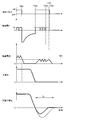
- FIG. 6 is an example of a timing chart of undershoot reduction control according to the first embodiment.
- the control unit drives the intermediate energization to the coil 303 within the next injection interval based on the detected initial position return timing (T605 in FIG. 5).
- T605 initial position return timing
- the behavior of the mover 306 after the injection pulse signal is turned off will be described below.
- a period Tc1 between times T601 and T605 (corresponding to T501 to T506 in FIG. 5) is an injection interval (injection interval period) of this embodiment.
- the fuel injection valve drive circuit 106 sets the voltage applied to the coil 303 to 0 V or less until the valve closing timing (T602). After reaching the valve closing timing (T602), the injection pulse signal is turned ON again (T602). When the injection pulse signal is ON, the fuel injection valve drive circuits 106a and 106b apply a drive voltage equal to or higher than the battery voltage VB to the coil 303.
- the ON time of the injection pulse signal (the injection pulse width Tp in FIG. 6) is calculated based on the undershoot time Tu obtained in FIG.
- the undershoot 608 (displacement) of the mover 306 after performing the undershoot reduction control becomes smaller than the undershoot 609 before performing the undershoot reduction control.
- the undershoot time (the period from T602 to T604) is shorter than the undershoot time Tu before the reduction control is performed, so that the next injection can be performed early.
- the fuel injection control device 101 (drive control unit 102) that controls at least the fuel injection valve 100 of the internal combustion engine performs a process of detecting the drive state of the mover 306 of the fuel injection valve 100. That is, the drive control unit 102 detects the time until the mover 306 undershoots and the mover 306 reaches the initial position again after the valve body 301 of the fuel injection valve 100 is closed. Then, the drive control unit 102 supplies a drive current (applies a drive voltage) to the coil 303 to the extent that the valve body 301 does not open in order to suppress the undershoot of the mover 306 based on the detected time.
- a drive current applies a drive voltage
- the drive control unit 102 performs the above operation at the timing (T502, T602) when the valve body 301 contacts the valve seat 302 after the valve body 301 opens.
- Energization of the coil 303 for detection processing or reduction control is started.
- the detection process or the reduction control is executed at the same time when the state of the fuel injection valve 100 enters the injection interval.
- the detection process or the reduction control can be completed by effectively utilizing the injection interval and within the range of the injection interval.
- starting energization as described above also leads to early completion of intermediate energization.
- the drive control unit 102 in the present embodiment detects the initial position return timing T505 when the movable portion (movable element 306) reaches the initial position Pi after the valve body 301 is closed (initial position return).
- the timing detection process) and the control for performing intermediate energization of the coil 303 based on the initial position return timing T505 are independently performed. However, as shown in FIG. 8 to be described later, the detection processing and the reduction control may be performed in parallel.
- FIG. 7 is a flowchart showing a procedure example of a fuel injection control process by the fuel injection control device 101 according to the first embodiment.
- the CPU 101a of the ECU 320 executes the program stored in the memory 101b, whereby the processing of each step shown in FIG. 8 is realized.
- the drive control unit 102 monitors whether or not the ignition switch signal (see FIG. 3) is ON (S1), and when the ignition switch signal is OFF (NO in S1), the ignition switch signal is ON. The process of this step is repeated until.
- the drive control unit 102 has performed the behavior detection process (initial position return timing detection process) of the mover 306 within the injection interval time. Is determined (S2). When the behavior detecting process of the mover 306 is not performed (NO in S2), the drive control unit 102 repeats the process of this step until the behavior detecting process of the mover 306 is performed.
- the fuel injection valve pulse width calculation unit 102a detects the behavior of the mover 306 based on the result of the behavior detection process of the mover 306.
- the operation stabilization time pulse width of the injection pulse signal
- the drive control unit 102 outputs the fuel injection valve drive pulse signal for performing the intermediate energization after performing the process of detecting the initial position return timing T505 based on the result of the process of detecting the initial position return timing T505.
- the pulse width Tp is set to be equal to or less than the time until the movable portion (movable element 306) reaches the initial position Pi after the valve body 301 is closed before the process of detecting the initial position return timing T505 is performed.
- the injection pulse width is set to be equal to or less than the undershoot time before the undershoot reduction control is performed. can do.
- the behavior of the movable part can be expected to be stable by limiting the time for energizing the coil 303 to the time until the movable part returns to the initial position.
- the drive control unit 102 sets the pulse width of the fuel injection valve drive pulse signal for performing the intermediate energization after performing the process of detecting the initial position return timing T505 to the movable portion (after the valve body 301 is closed).
- the length is set to half the time until the initial position return timing when the mover 306) reaches the initial position.
- the injection pulse width Tp is set to half the undershoot time Tu (Tu/2).
- the movable portion (movable element 306) is reliably moved while moving in the direction away from the fixed portion (fixed core 310).
- a drive current can be supplied to the coil 303. This makes it possible to stabilize the behavior of the movable part.
- the drive control unit 102 determines whether to perform multi-stage injection (S4).
- the drive control unit 102 performs fuel control including behavior control (undershoot reduction control) of the mover 306 after valve closing according to the present embodiment, based on the operation stabilization time. Injection control is performed (S5).
- the drive control unit 102 performs the normal fuel injection control without performing the behavior control of the mover 306 after the valve is closed according to the present embodiment ( S6).
- the drive control unit 102 monitors whether or not the ignition switch signal is OFF (S7). If the ignition switch signal is ON (NO in S7), the drive control unit 102 proceeds to the determination process in step S4 and multi-stage. Whether or not injection is performed is determined. When the ignition switch signal is OFF (YES in S7), the drive control unit 102 ends the process of this flowchart.
- the state (timing of returning to the initial position) can be detected.
- a drive current is applied to the coil 303 based on the detection result to return the mover 306 to the pre-injection state (initial position Pi) early and shorten the injection interval of the fuel injection valve 100. be able to.
- the injection interval in the undershoot reduction control can be adjusted for each fuel injection valve 100, the injection interval can be set for each fuel injection valve 100 without considering individual differences of the fuel injection valve 100.
- the actual behavior of the fuel injection valve 100 can be set based on the result of the child behavior detection processing.
- the second embodiment is an example in which the initial position return timing detection process and the undershoot reduction control are performed in parallel.
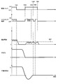
- FIG. 8 is an example of a timing chart when the initial position return timing detection process and the undershoot reduction control according to the second embodiment are performed in parallel.
- the difference between the present embodiment and the first embodiment is that the undershoot time detection control and the undershoot reduction control are not performed independently but are performed simultaneously.
- the drive control unit 102 applies a drive voltage equal to or higher than the battery voltage VB to the coil 303 after the valve is closed (T502). In FIG. 8, the battery voltage VB is used as the drive voltage.
- the fuel injection valve drive circuit 106a performs the switching operation so that the target current value 707 is set in advance.
- the length of the ON time (ejection pulse width) of the ejection pulse signal is not fixed.
- the drive control unit 102 determines that it is the timing when the mover 306 reaches the collision surface of the valve body 301, and stops applying the drive voltage. At this time, it does not matter whether the electric charge is extracted by the counter electromotive force (see FIG. 12 described later). This makes it possible to execute the undershoot reduction control while monitoring the behavior of the mover 306.
- the drive control unit 102 detects the initial position return timing when the movable part (movable element 306) reaches the initial position Pi after the valve body 301 is closed during the execution of the intermediate energization. When this is done, control is performed to stop energizing the coil 303. As a result, it becomes possible to perform the initial position return timing detection processing and the undershoot reduction control within one injection interval period, and compared with the case of the first embodiment, the multi-stage injection within a fixed time The number of times can be increased.
- the information of the undershoot time Tu is obtained in advance by the detection process of FIG. 5, and the injection pulse width (the period of T502 to T705) that is the ON time of the injection pulse signal is determined. You may keep it. Then, when the initial position return timing is detected (T704), the injection pulse signal is turned off (T705).
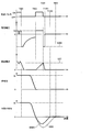
- FIG. 9 is an example of a timing chart of the initial position return timing detection process according to the third embodiment.
- the difference between the third embodiment and the first embodiment is that the switching operation is directly monitored instead of the drive voltage or the drive current as a means for detecting the undershoot time.
- the injection pulse is turned on again at the timing (T502) when the valve body 301 collides with the valve seat 302.
- the fuel injection valve drive circuit 106a applies the battery voltage VB to the coil 303 and performs a switching operation so that the target current value 807 becomes a predetermined target current value 807.
- the drive control unit 102 monitors the ON time of the switching operation, and monitors that the switching interval corresponding to when the mover 306 reaches the collision surface of the valve body 301 becomes long.
- the drive control unit 102 (fuel injection valve pulse width calculation unit 102a) according to the third embodiment performs the coil operation until the drive current reaches the target current value 807 after the drive voltage is applied to the coil 303.
- the time when the ON time of the switching operation for applying the drive voltage to 303 (the period from T803 to T804) exceeds the threshold value is determined as the initial position return timing (T804).
- the initial position return timing (T804) can be detected based on the switching operation of the transistor of the fuel injection valve drive circuit 106a without measuring the drive current or drive voltage.
- FIG. 10 is an example of a timing chart of undershoot reduction control according to the fourth embodiment.
- the difference between the fourth embodiment and the first embodiment is that two or more target current values are set in advance for undershoot reduction control.
- the injection pulse signal is turned on again at the timing (T602) when the valve body 301 collides with the valve seat 302.
- the fuel injection valve drive circuit 106a applies a drive voltage of a voltage equal to or higher than the battery voltage VB (high voltage VH in the figure) to the coil 303.
- FIG. 10 shows an example in which the boosted high voltage VH is applied to the coil 303, the battery voltage VB may be used.
- the application time of the battery voltage VB is set to be longer than the application time of the high voltage VH.
- the fuel injection valve drive circuit 106a applies the high voltage VH until the drive current of the coil 303 reaches a predetermined first target current value 906, and when it reaches the first target current value 906 (T903). , The application of the drive voltage is temporarily stopped. After that, the fuel injection valve drive circuit 106a applies the battery voltage VB to the coil 303 again so that the drive current of the coil 303 reaches the predetermined second target current value 907 (T904 to T905), and performs the switching operation. I do.
- the control unit (drive control unit 102) according to the fourth embodiment sets the first target current value (first target current value 906) as the target current value of the drive current during intermediate energization, A second target current value (second target current value 907) smaller than the first target current value is set in the memory 101b. Then, the control unit applies the drive voltage until the drive current supplied to the coil 303 when the valve body 301 is closed reaches the first target current value, and the drive current reaches the first target current value. Then, the application of the drive voltage is once stopped, and then the drive voltage is controlled so that the drive current supplied to the coil 303 is maintained at the second target current value.
- the mover 306 is moved to the valve seat immediately after the valve element 301 is closed.
- the moving force toward the direction of 302 can be suppressed by the magnetic attraction force in the valve opening direction. Therefore, the undershoot of the mover 306 can be reduced.
- the fifth embodiment is an example in which two or more types of drive currents are set and a reverse drive voltage is applied when switching the drive currents.
- FIG. 11 is an example of a timing chart of undershoot reduction control according to the fifth embodiment.
- the present embodiment is different from the fourth embodiment in that the counter electromotive force is used when the drive current is switched (for example, T1003) at two or more target current values set in advance, and the electric charge is extracted from the coil 303. is there.
- the control unit uses the first target current value (first target current value 1007) and the first target current value as the target current value of the drive current during intermediate energization.
- a second target current value smaller than the second target current value (second target current value 1008) is set in the memory 101b. Then, the control unit applies the drive voltage until the drive current supplied to the coil 303 when the valve body 301 is closed reaches the first target current value 1007, and the drive current becomes the first target current value 1007.
- a drive voltage (reverse voltage 1006) having a polarity opposite to the polarity of the drive voltage applied before the drive current reaches the first target current value 1007 is applied to the coil 303.
- the control unit applies the drive voltage so that the drive current supplied to the coil 303 becomes the second target current value 1008 until the ejection pulse signal is turned off (T1005).
- the polarity of the drive voltage (second target current value 1008) applied to the coil 303 again after the reverse voltage 1006 is applied is before the drive voltage has the opposite polarity. It has the same polarity as the voltage (positive polarity in FIG. 12).
- FIG. 12 is an example of a timing chart of undershoot reduction control according to the sixth embodiment.
- the first to third transistors 203, 204, 205 are turned off at the time when the drive current reaches the target current value 607 (T603) during intermediate energization.
- a drive voltage of 0 V or less (reverse polarity) is applied to the coil 303.
- T1301 the set time has elapsed
- only the third transistor 205 is turned on, and the drive voltage of the coil 303 is set to 0V.
- the displacement of the mover 306 accompanied by the undershoot 609A whose initial position return timing becomes T1302 is obtained.
- the drive control unit 102 (fuel injection valve pulse width calculation unit 102a) applies the drive voltage applied before the end of the intermediate energization at the end of the intermediate energization (T603).
- a drive voltage (reverse voltage 1303) having a polarity opposite to the polarity of is applied to the coil 303.
- the control of the drive voltage and the drive current shown in FIG. 12 can be applied to the undershoot reduction control in the first to fifth embodiments.
- the internal structure of the fuel injection valve 100 is configured such that the mover 306 pulled up in the valve opening direction by the magnetic attraction force contacts the collision surface of the valve body 301.
- the configuration is not limited to this.
- the fuel injection valve may include a preliminary stroke mechanism that secures a space in which the mover runs before the mover collides with the valve element.
- FIG. 13 is a diagram showing a structural example of a fuel injection valve provided with an intermediate stroke mechanism according to the seventh embodiment.
- the fuel injection valve 100A shown in FIG. 13 is greatly different from the fuel injection valve 100 shown in FIG. 3 in the presence of the preliminary stroke mechanism including the intermediate member 1201. Note that, in FIG. 13, in order to explain the principle of the preliminary stroke mechanism, the internal structure, the shape of parts, etc. are exaggerated or omitted.
- the fuel injection valve 100A has an intermediate member 1201 and a spring 1202 with respect to the fuel injection valve 100.
- the valve body 301A corresponds to the valve body 301.
- the valve body 301A is formed to have a first flange portion 1210 and a second flange portion 1211, and the first flange portion 1210 contacts the set spring 309.
- the mover 306A corresponds to the mover 306.
- the intermediate member 1201 which is a component of the preliminary stroke mechanism is a column having one bottom surface. An opening for inserting the valve body 301A is formed in the center of the bottom surface thereof.
- the cross-sectional shape of the intermediate member 1201 is approximately a hook shape.
- the lower end surface 1201b of the intermediate member 1201 contacts and separates from the upper surface (collision surface) of the mover 306A, and the upper end surface 1201a contacts the spring 1202. With such a configuration, the intermediate member 1201 functions as a movable portion.
- the initial position Pi is the position of the mover 306A in the non-energized state of the coil 303 before fuel injection.
- the movable element 306A When the coil 303 is energized, the movable element 306A is pulled up by the fixed core 310 from the initial position Pi toward the valve opening direction. Then, in a state where the mover 306A is running and gaining momentum, the collision surface of the mover 306A collides with the lower end surface 1201b of the intermediate member 1201. Then, the intermediate member 1201 moves in the valve opening direction together with the mover 306A, and the upper end surface 1201a of the intermediate member 1201 collides with the spring 1202. As a result, the force of the mover 306A is transmitted to the valve body 301A via the intermediate member 1201 (and also the spring 1202 in FIG. 13). The upper end surface 1201a of the intermediate member 1201 may directly collide with the first flange 1210 of the valve body 301A.
- any movable part for example, the mover 306, 306A or the valve body 301, 301A, or the intermediate member 1201 pulled up in the valve opening direction by the magnetic attraction force is arranged or formed inside the fuel injection valve 100.
- the fixed part (fixed core 310 or other fixed part) may be configured to collide (contact).
- each of the above-described embodiments is a detailed and specific description of the configuration and operation of the fuel injection control device 101 in order to explain the present invention in an easy-to-understand manner, and is not necessarily limited to one including all the described components. Not done. Further, it is possible to replace a part of the configuration of one embodiment with the constituent elements of another embodiment. It is also possible to add the components of another embodiment to the configuration of one embodiment. In addition, it is possible to add, delete, or replace other components with respect to a part of the configuration of each embodiment.
- each of the above-mentioned configurations, functions, processing units, etc. may be realized in hardware by designing a part or all of them with, for example, an integrated circuit.
Landscapes
- Engineering & Computer Science (AREA)
- Chemical & Material Sciences (AREA)
- Combustion & Propulsion (AREA)
- Mechanical Engineering (AREA)
- General Engineering & Computer Science (AREA)
- Fuel-Injection Apparatus (AREA)
- Electrical Control Of Air Or Fuel Supplied To Internal-Combustion Engine (AREA)
Abstract
先の噴射終了から次の噴射開始までの間に、燃料噴射弁の可動子の状態を把握する。そのため、燃料制御弁を制御するための制御装置101は、弁体301が弁座302に当接して閉弁した後、可動部306が固定部310から離れる方向へ変位した状態においてコイル303をスイッチング動作により通電し、コイル303に駆動電圧が印加されてからコイル303に供給される駆動電流が目標電流値へ変化するまでにかかる時間の長さの変化に基づいて、弁体301が閉弁した後に可動部306が初期位置に到達する初期位置復帰タイミングを検出する処理を行う制御部102を備える。
Description
本発明は、燃料噴射弁を制御する制御装置及びプログラムに関する。
一般的に内燃機関の制御装置は、燃料噴射弁の多段噴射(「分割噴射」とも呼ばれる)を制御するとき、燃料噴射を実施後に、燃料噴射弁が次の燃料噴射を実施することが可能となるまで噴射間隔(時間間隔)を設けている。これは、燃料噴射弁が有する可動子と弁体を燃料噴射前の状態に戻すためである。しかし、環境性能向上のため多段噴射の噴射段数の増加が要求されており、噴射間隔が長いと噴射段数の増加要求を満足できない。
このため、先の噴射終了から次の噴射開始までの間に、可動子を早期に噴射前の状態に戻すため、開弁力を発生するコイルに駆動電流を投入する制御が行われている。例えば、特許文献1には「弁体と弁座とが接触した閉弁状態から、コイルに通電することにより可動子に吸引力を作用させ、弁体を開弁方向に駆動して開弁状態に至らしめる燃料噴射弁にあっては、開弁状態から閉弁状態への閉弁動作時に、弁体が弁座に衝突した後にコイルへの通電を行い、可動子に対して閉弁動作の向きとは反対向きの力(すなわち吸引力)を作用させる。」ことが記載されている。
また、特許文献2には「先の燃料噴射(第1の燃料噴射)と後の燃料噴射(第2の燃料噴射)との間に、開弁しない程度の電圧印加を行って中間電流を流す。この中間電流を流すための電圧印加は、先の燃料噴射で弁体が閉弁する前に開始し、先の燃料噴射で弁体が閉弁した第1の時点から後の燃料噴射で電流供給を開始する第2の時点までの間の時間の半分の時間が第1の時点から経過する前に打ち切る。」ことが記載されている。
しかしながら、特許文献1及び特許文献2に記載の技術では、先の燃料噴射に対する噴射パルスをOFFした後、コイルに駆動電流を投入して中間通電することにより、可動子の状態によっては可動子を噴射前の状態に戻す効果とは逆の効果を発生させる恐れがある。その理由は、可動子の状態を把握せずに、コイルへの駆動電流の投入を実施してしまうからである。
本発明は、上記の状況に鑑み、先の噴射終了から次の噴射開始までの間に、燃料噴射弁の可動子の状態を把握することを目的とする。
上記課題を解決するために、本発明の一態様の燃料噴射弁を制御する制御装置は、弁座と当接することによって燃料通路を閉じて閉弁し、弁座から離れることによって燃料通路を開けて開弁する弁体と、この弁体を駆動する可動部と、電流が流れることで磁気吸引力を生じさせるコイルと、磁気吸引力により可動部を吸引する固定部と、を有し、弁体が弁座に当接して閉弁した後、可動部がコイルに通電していないときの初期位置に戻るように構成された燃料噴射弁を制御する制御装置である。そして、制御装置は、弁体が弁座に当接して閉弁した状態において、コイルをスイッチング動作により通電する中間通電を行うように構成された制御部、を備える。この制御部は、弁体が弁座に当接して閉弁した後、可動部が固定部から離れる方向へ変位した状態においてコイルをスイッチング動作により通電し、コイルに駆動電圧が印加されてからコイルに供給される駆動電流が目標電流値へ変化するまでにかかる時間の長さの変化に基づいて、弁体が閉弁した後に可動部が初期位置に到達する初期位置復帰タイミングを検出する処理を行う。
本発明の少なくとも一態様によれば、先の噴射終了から次の噴射開始までの間に、燃料噴射弁の可動子の状態(初期位置復帰タイミング)を検出することができる。例えば、検出結果を元にコイルに駆動電流を供給することで、早期に可動子を噴射前の状態に戻し、燃料噴射弁の噴射間隔を短縮することができる。
上記した以外の課題、構成及び効果は、以下の実施形態の説明により明らかにされる。
上記した以外の課題、構成及び効果は、以下の実施形態の説明により明らかにされる。
以下、本発明を実施するための形態(以下、「実施形態」と記述する)の例について、添付図面を参照して説明する。本明細書及び添付図面において実質的に同一の機能又は構成を有する構成要素については、同一の符号を付して重複する説明を省略する。
<1.第1の実施形態>
本発明は、燃料噴射弁を制御するマイクロコンピュータが燃料噴射弁の動作状態を監視して、少なくとも弁体を駆動する可動子の位置を検出し、早期に次の噴射が可能となるよう可動子の動作を制御する。まず、本発明の第1の実施形態に係る内燃機関システムに搭載される燃料噴射制御装置について説明する。燃料噴射制御装置は、燃料噴射弁を制御する制御装置である。
本発明は、燃料噴射弁を制御するマイクロコンピュータが燃料噴射弁の動作状態を監視して、少なくとも弁体を駆動する可動子の位置を検出し、早期に次の噴射が可能となるよう可動子の動作を制御する。まず、本発明の第1の実施形態に係る内燃機関システムに搭載される燃料噴射制御装置について説明する。燃料噴射制御装置は、燃料噴射弁を制御する制御装置である。
図1は、第1の実施形態に係る内燃機関システムが備える燃料噴射制御装置の構成例を示すブロック図である。図1に示す燃料噴射制御装置101は、後述する図3に示すようにECU(Engine Control Unit)320に内蔵されている。本実施形態は、燃料噴射弁100を筒内直接噴射式エンジンに適用した例であるが、燃料噴射弁100の利用形態はこの例に限らない。
図1に示す内燃機関システムでは、不図示のバッテリの電源が、ヒューズ108とリレー109を介して、ECU320内に備わる燃料噴射制御装置101へ供給される。
燃料噴射制御装置101は、エンジンの運転状態に応じて適切な通電時間及び噴射開始タイミングの演算を行い、バッテリの電源を元に、燃料噴射弁100のコイル(開弁駆動の電磁ソレノイド)303へ駆動電流(励磁電流)を供給するものである。燃料噴射制御装置101は、基本的に、エンジン状態検知部103、駆動制御部102(制御部の一例)、駆動IC104、高電圧生成回路105、燃料噴射弁駆動回路(Hi)106a、及び燃料噴射弁駆動回路(Lo)106bを備えている。
エンジン状態検知部103は、図示しない内燃機関(エンジン)の回転数、吸入空気量、冷却水温度、燃料圧力や内燃機関の故障状態などの各種情報を集約して、駆動制御部102へ提供する。
駆動制御部102は、燃料噴射弁パルス幅演算部102aと燃料噴射弁駆動波形指令部102bを備える。燃料噴射弁パルス幅演算部102aは、エンジン状態検知部103から得られる各種情報(内燃機関の運転状態)に基づき、燃料噴射弁100の燃料噴射期間を規定する燃料噴射パルスのパルス幅(以下「噴射パルス幅」と称することがある。)を演算し、駆動IC104へ出力する。
燃料噴射弁駆動波形指令部102bは、燃料噴射弁100の開弁を行うために又は開弁状態を維持するために供給する駆動電流の指令値(駆動電流波形)を算出し、駆動IC104へ出力する。燃料噴射弁駆動波形指令部102bは、燃料噴射弁パルス幅演算部102aの演算結果と、内燃機関の運転状態に基づいて、燃料噴射弁100のコイル303に供給する駆動電流の波形(電流プロフィール)を選択する。
高電圧生成回路105は、バッテリから供給されるバッテリ電圧VB(図2参照)を元に、電磁ソレノイド式の燃料噴射弁100が開弁する際に必要となる高い電源電圧(以下「高電圧」と称す)VHを生成する。高電圧生成回路105は、駆動IC104からの指令に基づき、所望の目標高電圧に至るようにバッテリ電圧VBを昇圧する。これにより、燃料噴射弁100の電源として、弁体301(図3参照)の開弁力の確保を目的とした高電圧VHと、開弁した後に弁体301が閉弁しないように開弁状態を保持させるバッテリ電圧VBの2系統が備わることになる。
燃料噴射弁100の上流側と下流側には、2つの燃料噴射弁駆動回路106a,106bが備えられており、2つの燃料噴射弁駆動回路106a,106bによって燃料噴射弁100に対して駆動電流の供給を行う。燃料噴射弁駆動回路106a,106bの構成の詳細は後述するため、ここでの説明は省略する。
駆動IC104は、燃料噴射弁パルス幅演算部102aで演算された噴射パルス幅と、燃料噴射弁駆動波形指令部102bで演算された駆動電流波形(電流プロフィール)とに基づき、燃料噴射弁駆動回路106a及び燃料噴射弁駆動回路106bに駆動信号を出力する。駆動IC104は、燃料噴射弁駆動回路106a及び燃料噴射弁駆動回路106bを制御することにより、燃料噴射弁100のコイル303に印加される高電圧VHもしくはバッテリ電圧VBを制御する。このようにして、駆動IC104は、燃料噴射弁100のコイル303に所望の駆動電流を供給し、燃料噴射弁100の燃料噴射の駆動及び制御を行い、内燃機関の燃焼に必要な燃料噴射量を最適に制御する。
次に、図1で示した燃料噴射弁100の燃料噴射弁駆動回路106a、106bの説明を行う。
図2は、燃料噴射弁駆動回路106a,106b及びその周辺回路を示す回路図である。燃料噴射弁駆動回路106aは、スイッチング素子を含み、高電圧生成回路105とコイル303との間、かつ、リレー109とコイル303との間に接続されている。燃料噴射弁駆動回路106aは、燃料噴射弁100に対し、高電圧生成回路105で生成された高電源電圧(高電圧VH)と、バッテリ電源である低電源電圧(バッテリ電圧VB)の何れかを選択し、燃料噴射弁100のコイル303に、選択した電源電圧を供給する。燃料噴射弁100が閉弁から開弁する際には、高電圧VH(高電圧電源)を選択して供給することで、開弁に必要な電流(駆動電流)を燃料噴射弁100のコイル303に通電する。
燃料噴射弁100の開弁状態を維持する場合には、電源電圧をバッテリ電圧VB(低電源電圧)に切り替えて、燃料噴射弁100のコイル303に保持電流(駆動電流)を流す。
燃料噴射弁100の開弁状態を維持する場合には、電源電圧をバッテリ電圧VB(低電源電圧)に切り替えて、燃料噴射弁100のコイル303に保持電流(駆動電流)を流す。
燃料噴射弁駆動回路106aは、燃料噴射弁100を開弁させるために必要となる電流を供給するため、高電圧VHを図中の高電圧生成回路105から、電流逆流防止のために備わるダイオード201を介し、図中の第1のトランジスタ203を含む回路を用いて、燃料噴射弁100に供給する。トランジスタはスイッチング素子の一例であり、バイポーラトランジスタやMOSトランジスタなどが用いられる。
一方、燃料噴射弁100を開弁させた後は、燃料噴射弁100の開弁状態を保持するために必要となるバッテリ電圧VBを高電圧VHと同様に、電流逆流防止のためのダイオード202を介し、図中の第2のトランジスタ204を含む回路を用いて、燃料噴射弁100に供給する。
燃料噴射弁駆動回路106bは、燃料噴射弁駆動回路106aと同様に、燃料噴射弁100に駆動電流を流す(供給する)ための燃料噴射弁100の下流に設けた駆動回路である。燃料噴射弁駆動回路106bには、第3のトランジスタ205が備わっており、この第3のトランジスタ205をONにすることで、上流側の燃料噴射弁駆動回路106aから供給される電源を燃料噴射弁100に印加することができる。また、駆動制御部102は、シャント抵抗206によって、燃料噴射弁100にて消費した電流を検知することで、後述する所望の燃料噴射弁100の電流制御を行う。以降の説明で、燃料噴射弁駆動回路106aと燃料噴射弁駆動回路106bを特に区別しない場合又は総称する場合には、「燃料噴射弁駆動回路106」と記す。
また、コイル303の下流側と高電圧生成回路105との間にダイオード209が順方向に接続され、シャント抵抗206とコイル303の上流側との間にダイオード208が順方向に接続されている。第1のトランジスタ203、第2のトランジスタ204、及び第3のトランジスタ205をOFFにすると、燃料噴射弁100のコイル303に生じる逆起電力によって、ダイオード208とダイオード209が通電する。それにより、電流が高電圧生成回路105側へ帰還され、コイル303に供給されていた駆動電流は急速に低下する。このとき、コイル303の端子間には、逆起電力として、高電圧VHに相当する大きさで逆極性の電圧(-VH)が生じる。
なお、本実施形態は、燃料噴射弁100の駆動方法について一例を示したものであり、例えば、燃料圧力が比較的低い場合などにおいて、燃料噴射弁100の開弁動作時に高電圧VHではなくバッテリ電圧VBを用いてもよい。
[燃料噴射弁の構造]
次に、燃料噴射弁100の構造について説明する。図3は、燃料噴射弁100の構造例を示す断面図である。燃料噴射弁100は、通常時閉弁型の電磁弁を備える電磁式燃料噴射装置である。図3に示す燃料噴射弁100の構造は一例であって、この例に限らないことは勿論である。
次に、燃料噴射弁100の構造について説明する。図3は、燃料噴射弁100の構造例を示す断面図である。燃料噴射弁100は、通常時閉弁型の電磁弁を備える電磁式燃料噴射装置である。図3に示す燃料噴射弁100の構造は一例であって、この例に限らないことは勿論である。
燃料噴射弁100は、内部に略棒状の弁体301を有し、弁体301の下端部と対向する位置には、弁座302が形成されたオリフィスカップが設けられている。弁座302には、燃料を噴射する噴孔302hが形成されている。弁体301の上方には、弁体301を閉弁方向(下方向)に付勢するスプリング309が設けられている。
また、燃料噴射弁100は、内部に弁体301が配置された中空のハウジング311を備える。ハウジング311の内面には固定コア310(固定部の一例)が固定されており、さらに燃料噴射弁100の内部には、ソレノイド状のコイル303が燃料噴射弁100の中心軸を一周するように配置されている。
燃料噴射弁100の中心軸には、上下に動く弁体301が配置されている。弁体301の周りを一周するように、可動コアである可動子306(可動部の一例)が配置されている。コイル303を囲むようにして、固定コア310、可動子306、及びハウジング311に、環状の磁気通路が形成される。
ハウジング311の内部の空間(燃料通路)は燃料で満たされており、コイル303に電流が流れると、可動子306がコイル303に引き寄せられる。そして、弁体301の下端部が弁座302から離れると、それまで弁体301によって閉じられていた、ハウジング311に開けられた噴孔302h(燃料通路出口)から燃料が噴射される。
弁体301の上方には、弁体301を弁座302の方向に押さえつける(付勢する)セットスプリング309が配置される。また、可動子306の下方において、可動子306とハウジング311との間には、可動子306を開弁方向に付勢するゼロスプリング304が配置される。燃料噴射後の非通電状態における可動子306は、各スプリングの荷重の釣り合いによって初期位置Pi(変位ゼロ)に戻る。可動子306が初期位置Piにあるとき、可動子306と固定コア310との間には間隙G1が生じている。
コイル303の巻始め端部及び巻終わり端部には剛性のある導体315が固定されている。導体315を介して、コイル303とECU320とが電気的に接続されている。ECU320はマイクロコンピュータの一例であり、燃料噴射制御装置101を内包する。また、燃料噴射制御装置101は、一例としてCPU101a及びメモリ101bを備える。
CPU101aは、演算処理を行うプロセッサである。メモリ101bは、揮発性又は不揮発性の半導体メモリ等よりなる記憶部である。メモリ101bには、燃料噴射弁100を制御するためのコンピュータープログラムが格納されていてもよい。この場合、CPU101aが、メモリ101bに記録されたコンピュータープログラムを読み出して実行することにより、燃料噴射制御装置101の機能の全部又は一部が実現される。ECU320には、内燃機関の始動(点火)を指令するためのイグニッションスイッチ信号が入力される。CPU101aは、イグニッションスイッチ信号がオンであることを検知すると、燃料噴射制御のコンピュータープログラムの処理を開始する。なお、CPU101aに代えてMPU(Micro Processing Unit)等の他の演算処理装置を用いてもよい。
以上のとおり、燃料噴射弁100を制御する制御装置(燃料噴射制御装置101)は、弁座302と当接することによって燃料通路を閉じて閉弁し、弁座302から離れることによって燃料通路を開けて開弁する弁体301と、弁体301を駆動する可動部(可動子306)と、電流が流れることで磁気吸引力を生じさせるコイル303と、磁気吸引力により可動部を吸引する固定部(固定コア310)と、を有する。また、制御装置(燃料噴射制御装置101)は、弁体301が弁座302に当接して閉弁した状態において、コイル303をスイッチング動作により通電する中間通電を行うように構成された制御部(駆動制御部102)を備えている。
そして、燃料噴射弁100は、弁座302から離れた弁体301が弁座302と再び当接して弁体301の閉弁方向への運動が止められた後において、可動部(可動子306)が弁体301との間で相対運動可能であるとともに、可動部がコイル303に通電していないときの初期位置に戻るように構成されている。
[従来の燃料噴射弁(可動子)の電流制御]
ここで、従来技術における燃料噴射弁(可動子)の電流制御と弁体挙動について図4を用いて説明する。制御対象の燃料噴射弁は、図3に示した燃料噴射弁100とする。
ここで、従来技術における燃料噴射弁(可動子)の電流制御と弁体挙動について図4を用いて説明する。制御対象の燃料噴射弁は、図3に示した燃料噴射弁100とする。
図4は、従来の燃料噴射弁100の駆動電流と可動子変位及び弁変位とを示すタイミングチャートの例である。一般的に、直噴式内燃機関の燃料噴射弁100を駆動する場合、燃料噴射弁100の特性に基づいて、駆動電流プロフィール403(駆動電流波形)を予め設定し、この駆動電流プロフィール403による燃料噴射弁100の噴射量特性をECU320(図3参照)内のメモリ101bに記録する。
燃料噴射制御装置101(燃料噴射弁パルス幅演算部102a)は、内燃機関(図示せず)の運転状態(吸入空気量)と燃料噴射弁100の噴射量特性とから、燃料噴射弁100の駆動指令時間(噴射パルス信号401)を算出する。噴射パルス信号401は、ECU320で演算された所望の噴射開始タイミングT404からONとなり、予めECU320内に記憶している駆動電流プロフィール403に基づき、燃料噴射弁100の電流制御が行われる。
図4の例における駆動電流プロフィール403は、燃料噴射弁100の開弁を行う開弁ピーク電流403a、開弁保持を行う第1保持電流403bなどの複数の目標とする電流値(目標電流値)から構成される。燃料噴射制御装置101は、予め設定された制御シーケンスに基づき、コイル303に供給する目標電流値(開弁ピーク電流403a、第1保持電流403b)を切り替えることで燃料噴射弁100の動作を制御する。このように、燃料噴射制御装置101は、噴射パルス信号401がOFFとなるタイミング(T408)まで燃料噴射弁100に対し、駆動電流を印加し続ける。
次に、従来の燃料噴射弁100の弁体301の挙動について図3及び図4を参照して説明する。噴射パルス信号401がONになってから(T404)、コイル303に供給する駆動電流が開弁ピーク電流403aに至るまで、駆動電圧402として高電圧VHが燃料噴射弁100のコイル303に印加される。燃料噴射弁100固有の電気的特性に基づく残留磁場が所定量となった時点(図4ではT405)で、コイル303の磁気吸引力がセットスプリング309のばね力よりも大きくなる。その結果、可動子306が開弁方向に移動を開始し、これに引き上げられる形で弁体301が弁座302から離れて開弁を開始する。
その後も、コイル303の駆動電流が開弁ピーク電流403aに至るまでの電流挙動による開弁力が持続することで、弁体301は、開弁動作を継続し、可動子306が固定コア310の位置Stに到達する(T406)。その際、余剰な開弁力により、弁体301はバウンシング動作を暫く行った後、安定した開弁状態へ以降する(T407)。時刻T406以降は、弁体301が閉弁しないように開弁状態を保持させるバッテリ電圧VBが、コイル303に印加される。
その後、噴射パルス信号401がOFFとなる時点(T408)まで完全に弁体301が開いた状態を持続し、その後、燃料噴射弁100の残留磁場が低下する。その結果、磁気吸引力を失った可動子306は、セットスプリング309の荷重(ばね力)と燃料圧力による力によって弁体301と共に、弁体301が弁座302に接触する閉弁位置まで押し戻され、完全に弁体301が閉弁する(T409)。
弁体301に働くセットスプリング309の力は、弁体301の衝突面及び可動子306の衝突面を介して可動子306に伝達される。しかし、弁体301が弁座302と接触した時(T409)、可動子306の衝突面は弁体301の衝突面から離脱し、閉弁方向(固定コア310から離れる方向)に運動を継続する。その後、可動子306にはゼロスプリング304によって開弁方向に押し戻す力が加わり、時刻T410で可動子306の衝突面が弁体301の衝突面に接触する。衝突後、可動子306は変位ゼロ、すなわち初期位置Piに維持される。
上記のように閉弁動作時、可動子306が弁体301を離れ、再び弁体301の衝突面に接触するまでの動作を「アンダーシュート」と呼ぶ。可動子306にアンダーシュートUSが発生している間、燃料噴射弁100は燃料を噴射することができない。これは、可動子306の衝突面が弁体301の衝突面に接触していないために、可動子306の位置によっては弁体301を開弁方向に移動させる力が安定しなくなり、その結果、燃料の噴射量がばらついてしまうからである。このため、可動子306を素早く初期位置Piに停止(復帰)させることで、アンダーシュートUSが発生している時間を短くする必要がある。
一方で、アンダーシュートUSを小さくする場合、可動子306が弁体301と接触する際の運動エネルギーを小さくする必要がある。余分な運動エネルギーにより可動子306が、弁体301に働く閉弁方向の力より大きい開弁方向の力を伝えてしまうと、再び弁体301が開弁してしまい、無駄な噴射を実施してしまう。したがって、可動子306の余分な運動エネルギーを抑えて無駄な噴射の実施を防止することが肝要である。
[第1の実施形態に係る燃料噴射弁(可動子)の電流制御]
次に、本実施形態に係る燃料噴射弁100の電流制御と弁体301の挙動について図5~図8を参照して説明する。本実施形態は、初期位置復帰タイミング検出処理とアンダーシュート低減制御の二つの行程から成り立つ。
次に、本実施形態に係る燃料噴射弁100の電流制御と弁体301の挙動について図5~図8を参照して説明する。本実施形態は、初期位置復帰タイミング検出処理とアンダーシュート低減制御の二つの行程から成り立つ。
(初期位置復帰タイミング検出処理)
図5は、第1の実施形態に係る初期位置復帰タイミング検出処理のタイミングチャートの例である。図5では、噴射パルス信号、燃料噴射弁100に供給する駆動電圧と駆動電流、弁体301と可動子306の挙動の関係が示されている。以下では、噴射パルス信号がOFFとなる時点以降の可動子306の挙動について説明する。
図5は、第1の実施形態に係る初期位置復帰タイミング検出処理のタイミングチャートの例である。図5では、噴射パルス信号、燃料噴射弁100に供給する駆動電圧と駆動電流、弁体301と可動子306の挙動の関係が示されている。以下では、噴射パルス信号がOFFとなる時点以降の可動子306の挙動について説明する。
図5において、噴射パルス信号がOFFとなった時(T501:図4のT408に相当)、燃料噴射弁駆動回路106は、コイル303に印加する駆動電圧を0V以下とし、駆動電流を低下させる。閉弁方向の力であるセットスプリング309による荷重と燃料圧力による力との和が、磁気吸引力よりも大きくなったとき、可動子306は弁体301と共に閉弁方向に移動を開始する。
その後、弁体301が弁座302に衝突するタイミング(T502)において再び噴射パルス信号をONとし、燃料噴射弁駆動回路106aは、コイル303にバッテリ電圧VBを印加する(T502からT506の期間)。そして、燃料噴射弁駆動回路106a(第2のトランジスタ203)は、予め定めた目標電流値507となるようにスイッチング動作を行う。T501~T506の期間Tc0は、従来の噴射インターバル期間に相当する。
弁体301が弁座302に衝突すると(T502)、可動子306の衝突面は弁座302の衝突面から離れる。そして、可動子306は、ゼロスプリング304の荷重を受けながら固定コア310から離れる方向に移動する。その後、ゼロスプリング304の荷重を受けて可動子306の移動方向が開弁方向に変化する(T503)。可動子306は、タイミング(T503)で弁体301の衝突面から最も離れた後、弁体301の衝突面に向かって移動する。
このとき、開弁方向に移動する可動子306が弁体301の衝突面に近づくほど磁場が強くなることで、コイル303の駆動電流の立ち上がりが緩やかになる。このため、スイッチング動作のON時間が長くなる(T504からT506の期間)。この結果、可動子306が弁体301の衝突面に到達したとき、スイッチングのON時間の長さが最も長くなる。したがって、このときを可動子306が弁体301の衝突面に到達したタイミング(T505)、すなわち、可動子306が初期位置Piに復帰したタイミングであると判断できる。
上記スイッチング動作のON時間は、スイッチング動作時に測定されるコイル303に対する駆動電流509又は駆動電圧508の波形より検出可能である。閉弁タイミング(T502)から上記可動子306が弁体301の衝突面に到達するタイミング(T505)までの期間をアンダーシュート時間Tuとする。燃料噴射弁パルス幅演算部102aは、上記の行程(初期位置復帰タイミング検出処理)を一つの燃料噴射弁100に対して少なくとも一回以上実施し、アンダーシュート時間Tuを決定する。
上述のとおり、制御部(駆動制御部102)は、弁体301が弁座302に当接して閉弁した後、可動部(可動子306)が固定部(固定コア310)から離れる方向へ変位した状態においてコイル303をスイッチング動作により通電する。そして、制御部(駆動制御部102)は、コイル303に駆動電圧508が印加されてからコイル303に供給される駆動電流509が目標電流値507へ変化するまでにかかる時間の長さの変化に基づいて、弁体301が閉弁した後に可動部(固定コア310)が初期位置に到達する初期位置復帰タイミング(T505)を検出する処理を行う。
例えば、駆動制御部102(燃料噴射弁パルス幅演算部102a)は、コイル303に駆動電圧が印加されてから駆動電流が目標電流値(目標電流値507)になるまでの時間の長さが閾値を超えた時点を、初期位置復帰タイミング(T505)であると判断する。
または、駆動制御部102(燃料噴射弁パルス幅演算部102a)は、コイル303に駆動電圧が印加されてから駆動電流が目標電流値(目標電流値507)になるまでに、コイル303に駆動電圧が印加された時間が閾値を超えた時点を、初期位置復帰タイミング(T505)であると判断する。
さらに、駆動制御部102(燃料噴射弁パルス幅演算部102a)は、コイル303への通電時に、弁体301が弁座302に当接した後、コイル303を開弁するときに用いる駆動電圧よりも低い駆動電圧(バッテリ電圧VB)を用いて、コイル303に供給する駆動電流が目標電流値(目標電流値507)となるようにコイル303を通電する。これにより、初期位置復帰タイミング検出処理時の電力消費が抑えられる。
(アンダーシュート低減制御)
次に、アンダーシュート低減制御について説明する。
図6は、第1の実施形態に係るアンダーシュート低減制御のタイミングチャートの例である。本実施形態では、制御部(駆動制御部102)は、検出した初期位置復帰タイミング(図5のT605)に基づいて、次の噴射間隔内でコイル303に対する中間通電を制御する。以下では、噴射パルス信号がOFFとなる時点以降の可動子306の挙動について説明する。時刻T601~T605(図5のT501~T506に対応)の期間Tc1は、本実施形態の噴射間隔(噴射インターバル期間)である。
次に、アンダーシュート低減制御について説明する。
図6は、第1の実施形態に係るアンダーシュート低減制御のタイミングチャートの例である。本実施形態では、制御部(駆動制御部102)は、検出した初期位置復帰タイミング(図5のT605)に基づいて、次の噴射間隔内でコイル303に対する中間通電を制御する。以下では、噴射パルス信号がOFFとなる時点以降の可動子306の挙動について説明する。時刻T601~T605(図5のT501~T506に対応)の期間Tc1は、本実施形態の噴射間隔(噴射インターバル期間)である。
図6に示すように、噴射パルス信号がOFFになった後(T601)、燃料噴射弁駆動回路106は、閉弁タイミング(T602)までコイル303への印加電圧を0V以下とする。閉弁タイミングに到達後(T602)、再び噴射パルス信号をONとする(T602)。噴射パルス信号がONのとき、燃料噴射弁駆動回路106a,106bは、コイル303にバッテリ電圧VB以上の駆動電圧を印加する。
上記噴射パルス信号のON時間(図6では噴射パルス幅Tp)は、図5で得られたアンダーシュート時間Tuに基づいて算出する。
これにより、可動子306は磁気吸引力によって開弁方向に力が働くため、閉弁方向の力が減衰する。この結果、アンダーシュート低減制御を実施後の可動子306のアンダーシュート608(変位)は、アンダーシュート低減制御を実施前のアンダーシュート609と比べて小さくなる。このように、低減制御実施後は、アンダーシュート時間(T602~T604の期間)が、低減制御実施前のアンダーシュート時間Tuよりも短くなるため、次の噴射が早期に可能となる。
このように本実施形態は、内燃機関の少なくとも燃料噴射弁100を制御する燃料噴射制御装置101(駆動制御部102)が、燃料噴射弁100の可動子306の駆動状態を検出する処理を行う。すなわち、駆動制御部102は、燃料噴射弁100の弁体301が閉弁後、可動子306がアンダーシュートして可動子306が再び初期位置に到達するまでの時間を検出する。そして、駆動制御部102は、検出した時間を元に可動子306のアンダーシュートを抑制するため、弁体301が開弁しない程度にコイル303に駆動電流を供給(駆動電圧を印加)する。
本実施形態では、図5及び図6に示したように、駆動制御部102は、弁体301が開弁後に弁体301が弁座302に当接したタイミング(T502、T602)で、上記の検出処理又は低減制御のためのコイル303への通電を開始する。このようにすることで、燃料噴射弁100の状態が噴射間隔に入る同時に、検出処理又は低減制御が実行される。それにより、噴射間隔を有効に利用して、且つ噴射間隔の範囲内で、検出処理又は低減制御を完了することができる。特に低減制御においては、上記のように通電を開始することで中間通電の早期完了にも繋がる。
上述したように、本実施形態における駆動制御部102は、弁体301が閉弁した後に可動部(可動子306)が初期位置Piに到達する初期位置復帰タイミングT505を検出する処理(初期位置復帰タイミング検出処理)と、初期位置復帰タイミングT505に基づいてコイル303に中間通電を行う制御(アンダーシュート低減制御)とをそれぞれ、独立して実施している。ただし、後述する図8に示すように、検出処理と低減制御を並行して実施する構成としてもよい。
[燃料噴射制御処理の手順例]
図7は、第1の実施形態に係る燃料噴射制御装置101による燃料噴射制御処理の手順例を示すフローチャートである。ECU320のCPU101aが、メモリ101bに格納されたプログラムを実行することにより、図8に示す各ステップの処理が実現される。
図7は、第1の実施形態に係る燃料噴射制御装置101による燃料噴射制御処理の手順例を示すフローチャートである。ECU320のCPU101aが、メモリ101bに格納されたプログラムを実行することにより、図8に示す各ステップの処理が実現される。
まず、駆動制御部102は、イグニッションスイッチ信号(図3参照)がONであるかどうかを監視し(S1)、イグニッションスイッチ信号がOFFである場合には(S1のNO)、イグニッションスイッチ信号がONになるまで本ステップの処理を繰り返す。
次に、駆動制御部102は、イグニッションスイッチ信号がONである場合には(S1のYES)、噴射インターバル時間内において可動子306の挙動検出処理(初期位置復帰タイミング検出処理)を実施したかどうかを判定する(S2)。駆動制御部102は、可動子306の挙動検出処理を実施していない場合には(S2のNO)、可動子306の挙動検出処理を実施するまで本ステップの処理を繰り返す。
次に、燃料噴射弁パルス幅演算部102aは、可動子306の挙動検出処理を実施した場合には(S2のYES)、可動子306の挙動検出処理の結果に基づいて、燃料噴射弁100の動作安定時間(噴射パルス信号のパルス幅)を決定する(S3)。
例えば、駆動制御部102は、初期位置復帰タイミングT505を検出する処理の結果に基づいて、初期位置復帰タイミングT505を検出する処理を実施した後の中間通電を行うための燃料噴射弁駆動パルス信号のパルス幅Tpを、初期位置復帰タイミングT505を検出する処理を実施する前の、弁体301が閉弁した後に可動部(可動子306)が初期位置Piに到達するまでの時間以下に設定する。
このように、弁体301が閉弁した後の可動部(可動子306)の初期位置復帰タイミングT505がわかることで、噴射パルス幅を、アンダーシュート低減制御を実施前のアンダーシュート時間以下に設定することができる。コイル303に通電する時間を、可動部が初期位置に復帰するまでの時間に限定することで、可動部の挙動が安定することが期待できる。
また、駆動制御部102は、初期位置復帰タイミングT505を検出する処理を実施した後の中間通電を行うための燃料噴射弁駆動パルス信号のパルス幅を、弁体301が閉弁した後に可動部(可動子306)が初期位置に到達した初期位置復帰タイミングまでの時間の半分の長さに設定する。例えば図6において、噴射パルス幅Tpを、アンダーシュート時間Tuの半分(Tu/2)の時間に設定する。
このように、中間通電において、噴射パルス幅Tpをアンダーシュート時間Tuの半分に設定することにより、可動部(可動子306)が固定部(固定コア310)から離れる方向へ移動中に確実に、コイル303に駆動電流を供給することができる。これにより、可動部の挙動をより安定させることが可能となる。
次に、駆動制御部102は、多段噴射を実施するか否かを判定する(S4)。多段噴射を実施する場合(S4のYES)、駆動制御部102は、上記動作安定時間に基づいて、本実施形態に係る閉弁後の可動子306の挙動制御(アンダーシュート低減制御)を伴う燃料噴射制御を実施する(S5)。
一方、多段噴射を実施しない場合(S4のNO)、駆動制御部102は、本実施形態に係る閉弁後の可動子306の挙動制御を実施せずに、通常の燃料噴射制御を実施する(S6)。
次に、駆動制御部102は、イグニッションスイッチ信号がOFFであるかどうかを監視し(S7)、イグニッションスイッチ信号がONである場合には(S7のNO)、ステップS4の判定処理に進んで多段噴射の実施有無を判定する。また、イグニッションスイッチ信号がOFFである場合には(S7のYES)、駆動制御部102は、本フローチャートの処理を終了する。
上述した第1の実施形態によれば、先の噴射終了から次の噴射開始までの間に、図5に示す可動子306の初期位置復帰タイミングの検出処理を実施することにより、可動子306の状態(初期位置復帰タイミング)を検出することができる。そして、中間通電時に、検出結果を元にコイル303に駆動電流を投入することで、早期に可動子306を噴射前の状態(初期位置Pi)に戻し、燃料噴射弁100の噴射間隔を短縮することができる。
また、燃料噴射弁100ごとに、アンダーシュート低減制御における噴射パルス幅を調整することができるので、燃料噴射弁100の個体差を考慮することなく、燃料噴射弁100ごとに噴射間隔を設定することができる。従来、多気筒の内燃機関では、噴射間隔が一番長い燃料噴射弁に合わせて多段噴射の噴射間隔を余裕のある値に設定していたが、本実施形態により多段噴射の噴射間隔を、可動子の挙動検出処理の結果を元に、実際の燃料噴射弁100の挙動を元に設定できる。
<2.第2の実施形態>
第2の実施形態は、初期位置復帰タイミング検出処理とアンダーシュート低減制御を並行して実施する例である。
第2の実施形態は、初期位置復帰タイミング検出処理とアンダーシュート低減制御を並行して実施する例である。
図8は、第2の実施形態に係る初期位置復帰タイミング検出処理とアンダーシュート低減制御を並行して実施する際のタイミングチャートの一例である。
本実施形態において第1の実施形態と異なる点は、アンダーシュート時間検出制御とアンダーシュート低減制御を独立して実施するものではなく、同時に実施する点である。駆動制御部102は、閉弁後(T502)に、バッテリ電圧VB以上の駆動電圧をコイル303に印加する。図8では、駆動電圧としてバッテリ電圧VBを用いている。このとき、燃料噴射弁駆動回路106aは、予め定めた目標電流値707となるようにスイッチング動作を行う。噴射パルス信号のON時間(噴射パルス幅)の長さは決まっていない。
図8の例において、T703から駆動電圧のON時間が長くなり、T704で駆動電圧を印加する時間の長さが閾値を超えたものとする。駆動制御部102は、T704の時点で、可動子306が弁体301の衝突面に到達するタイミングであると判断し、駆動電圧の印加を停止する。このとき、逆起電力による電荷引き抜き(後述する図12参照)の実施の有無は問わない。これによって、可動子306の挙動を監視した状態で、アンダーシュート低減制御を実行することが可能となる。
以上のとおり、第2の実施形態における駆動制御部102は、中間通電を実施中、弁体301が閉弁した後に可動部(可動子306)が初期位置Piに到達する初期位置復帰タイミングを検出した時に、コイル303への通電を停止する制御を行う。これにより、1回の噴射インターバル期間内で、初期位置復帰タイミング検出処理とアンダーシュート低減制御を実施することが可能となり、第1の実施形態の場合と比較して、一定時間内の多段噴射の回数を増加させることができる。
なお、第2の実施形態の変形例として、図5の検出処理により予めアンダーシュート時間Tuの情報を得て、噴射パルス信号のオン時間である噴射パルス幅(T502~T705の期間)を決定しておいてもよい。そして、初期位置復帰タイミングを検出したら(T704)、噴射パルス信号をOFFにする(T705)。
<3.第3の実施形態>
図9は、第3の実施形態に係る初期位置復帰タイミング検出処理のタイミングチャートの一例である。
図9は、第3の実施形態に係る初期位置復帰タイミング検出処理のタイミングチャートの一例である。
第3の実施形態において第1の実施形態と異なる点は、アンダーシュート時間を検出する手段として、駆動電圧または駆動電流ではなく直接スイッチング動作を監視する点である。まず、弁体301が弁座302に衝突するタイミング(T502)で再び噴射パルスをONとする。燃料噴射弁駆動回路106aは、コイル303にバッテリ電圧VBを印加し、予め定めた目標電流値807となるようにスイッチング動作を行う。駆動制御部102は、スイッチング動作のON時間を監視し、可動子306が弁体301の衝突面に到達した時に相当するスイッチングの間隔が長くなる点を監視する。
以上のとおり、第3の実施形態に係る駆動制御部102(燃料噴射弁パルス幅演算部102a)は、コイル303に駆動電圧が印加されてから駆動電流が目標電流値807になるまでに、コイル303に駆動電圧を印加するためのスイッチング動作のオン時間(T803からT804の期間)が閾値を超えた時点を、初期位置復帰タイミング(T804)と判断する。
これにより、駆動電流又は駆動電圧を測定することなく、燃料噴射弁駆動回路106aのトランジスタのスイッチング動作に基づいて、初期位置復帰タイミング(T804)を検出することができる。
<4.第4の実施形態>
図10は、第4の実施形態に係るアンダーシュート低減制御のタイミングチャートの一例である。
図10は、第4の実施形態に係るアンダーシュート低減制御のタイミングチャートの一例である。
第4の実施形態において第1の実施形態と異なる点は、アンダーシュート低減制御のために予め2種類以上の目標電流値を設定する点にある。弁体301が弁座302に衝突するタイミング(T602)において再び噴射パルス信号をONとする。それにより、燃料噴射弁駆動回路106aは、コイル303にバッテリ電圧VB以上(図中、高電圧VH)の大きさの駆動電圧を印加する。図10には、昇圧した高電圧VHをコイル303に印加した例が示されているが、バッテリ電圧VBでもよい。バッテリ電圧VBを用いる場合には、バッテリ電圧VBの印加時間は高電圧VHの印加時間よりも長い時間に設定する。
そして、燃料噴射弁駆動回路106aは、コイル303の駆動電流が予め定めた第1の目標電流値906に達するまで高電圧VHを印加し、第1の目標電流値906に達したとき(T903)、駆動電圧の印加を一旦停止する。その後、燃料噴射弁駆動回路106aは、コイル303の駆動電流が予め定めた第2の目標電流値907となるように、再度コイル303にバッテリ電圧VBを印加して(T904~T905)、スイッチング動作を行う。
以上のとおり、第4の実施形態に係る制御部(駆動制御部102)は、中間通電時における駆動電流の目標電流値として、第1の目標電流値(第1の目標電流値906)と、第1の目標電流値よりも小さい第2の目標電流値(第2の目標電流値907)が、メモリ101bに設定される。そして、制御部は、弁体301が閉弁した時にコイル303に供給される駆動電流が第1の目標電流値になるまで駆動電圧を印加して、駆動電流が第1の目標電流値に達したら駆動電圧の印加を一旦停止し、その後、コイル303に供給される駆動電流が第2の目標電流値で維持されるように駆動電圧を印加する制御を行う。
このように、弁体301が閉弁した直後により高い第1の目標電流値906を設定してコイル303に駆動電流を供給することで、弁体301の閉弁直後、可動子306が弁座302の方向へ向かう移動力を、開弁方向の吸引磁気力によって抑えることが可能となる。それゆえ、可動子306のアンダーシュートを低減させることができる。
<5.第5の実施形態>
第5の実施形態は、2種類以上の駆動電流を設定し、駆動電流の切り替え時に逆電圧の駆動電圧を印加する例である。
第5の実施形態は、2種類以上の駆動電流を設定し、駆動電流の切り替え時に逆電圧の駆動電圧を印加する例である。
図11は、第5の実施形態に係るアンダーシュート低減制御のタイミングチャートの一例である。本実施形態において第4の実施形態と異なる点は、予め設定する2種類以上の目標電流値において駆動電流の切り替え時(例えばT1003)に逆起電力を用いて、コイル303から電荷を引き抜く点である。
本実施形態に係る制御部(駆動制御部102)は、中間通電時における駆動電流の目標電流値として、第1の目標電流値(第1の目標電流値1007)と、第1の目標電流値よりも小さい第2の目標電流値(第2の目標電流値1008)がメモリ101bに設定される。そして、制御部は、弁体301が閉弁した時にコイル303に供給される駆動電流が第1の目標電流値1007になるまで駆動電圧を印加し、駆動電流が第1の目標電流値1007に達したら(T1003)、駆動電流が第1の目標電流値1007に達する前までに印加していた駆動電圧の極性とは逆極性の駆動電圧(逆電圧1006)を、コイル303に印加する。その後(T1004)、制御部は、噴射パルス信号がOFFするまで(T1005)、コイル303に供給される駆動電流が第2の目標電流値1008となるように駆動電圧を印加する。
本実施形態では、図11から理解されるように、逆電圧1006を印加後に再度コイル303に印加する駆動電圧(第2の目標電流値1008)の極性は、駆動電圧が逆極性となる前の電圧の極性と同じ(図12では正極性)である。
このように、逆電圧1006による逆起電力を用いてコイル303から一担電荷を引き抜いた後、再びコイル303に電荷を供給する。このように構成することで、逆起電力を用いて可動子306のアンダーシュートを抑制後、電荷の再供給により生じた残留磁気力によって、可動子306への弁体301の衝突面へ衝突する可動子306の移動力の増加を低減することができる。
<6.第6の実施形態>
図12は、第6の実施形態に係るアンダーシュート低減制御のタイミングチャートの一例である。
図12は、第6の実施形態に係るアンダーシュート低減制御のタイミングチャートの一例である。
図12に示すアンダーシュート低減制御では、中間通電時に駆動電流が目標電流値607になった時点(T603)で、第1~第3のトランジスタ203,204,205(図2参照)をOFFにして、コイル303に0V以下(逆極性)の駆動電圧を印加する。そして、設定時間が経過後(T1301)、第3のトランジスタ205のみをオンして、コイル303の駆動電圧を0Vとする。これにより、初期位置復帰タイミングがT1302となるアンダーシュート609Aを伴う可動子306の変位が得られる。
上記のとおり、第6の実施形態では、駆動制御部102(燃料噴射弁パルス幅演算部102a)は、中間通電の終了時(T603)、中間通電が終了する前までに印加していた駆動電圧の極性とは逆極性の駆動電圧(逆電圧1303)を、コイル303に印加する。
このように、中間通電の終了時に、コイル303に逆極性の駆動電圧を印加することで、コイル303に逆起電力を発生させて、コイル303から短時間で電荷を引き抜いて残留磁気力を低減することができる。それにより、コイル303の磁気吸引力が低下し、可動子306の開弁方向への移動速度が下がることから、可動子306が初期位置へ復帰(弁体301へ衝突する)ときの衝撃を弱めることができる。
図12に示す駆動電圧及び駆動電流の制御は、第1~第5の実施形態におけるアンダーシュート低減制御に適用することができる。
<7.第7の実施形態>
上述した第1~第6の実施形態において、燃料噴射弁100の内部構造を、磁気吸引力により開弁方向に引き上げられた可動子306が弁体301の衝突面に当接する構成としたが、この構成に限らない。例えば、燃料噴射弁が、可動子が弁体に衝突する前に可動子が助走する空間を確保した予備ストローク機構を備えていてもよい。
上述した第1~第6の実施形態において、燃料噴射弁100の内部構造を、磁気吸引力により開弁方向に引き上げられた可動子306が弁体301の衝突面に当接する構成としたが、この構成に限らない。例えば、燃料噴射弁が、可動子が弁体に衝突する前に可動子が助走する空間を確保した予備ストローク機構を備えていてもよい。
図13は、第7の実施形態に係る中間ストローク機構を備えた燃料噴射弁の構造例を示す図である。図13に示す燃料噴射弁100Aが図3に示した燃料噴射弁100と大きく異なる点は、中間部材1201を含む予備ストローク機構の存在である。なお、図13は、予備ストローク機構の原理を説明するために、内部構造や部品形状等を誇張又は省略して表現している。
燃料噴射弁100Aにおいて、燃料噴射弁100に対して、中間部材1201とスプリング1202を有している。弁体301Aは、弁体301に対応している。弁体301Aは、第1のつば部1210と第2のつば部1211を有するように形成されており、第1のつば部1210は、セットスプリング309と当接する。また、可動子306Aは、可動子306に対応している。
予備ストローク機構の構成要素である中間部材1201は、一つの底面を有する円柱状である。その底面の中央部には、弁体301Aが挿通される開口部が形成されている。中間部材1201の断面形状は、おおよそ鈎状である。中間部材1201の下端面1201bが可動子306Aの上面(衝突面)と接離し、上端面1201aがスプリング1202と当接する。このような構成では、中間部材1201は可動部として機能する。
可動子306Aが初期位置Piにあるとき、可動子306Aと弁体301Aの第2のつば部1211とは、間隙G2だけ離れている。初期位置Piは、燃料噴射前のコイル303が非通電状態における可動子306Aの位置である。
コイル303が通電すると、可動子306Aが、固定コア310により初期位置Piから開弁方向へ向かって引き上げられる。そして、可動子306Aが助走して勢いをつけた状態で、可動子306Aの衝突面が中間部材1201の下端面1201bに衝突する。そして、中間部材1201が可動子306Aとともに開弁方向に移動し、中間部材1201の上端面1201aがスプリング1202に衝突する。これにより、可動子306Aの力が、中間部材1201を介して(図13ではスプリング1202も介して)弁体301Aに伝達される。なお、中間部材1201の上端面1201aが直接、弁体301Aの第1のつば部1210に衝突するような構成でもよい。
このような予備ストローク機構を備えた燃料噴射弁に対して本発明の燃料噴射制御を適用した場合でも、上述した第1~第6の実施形態の構成と同様の効果が得られる。
なお、磁気吸引力により開弁方向に引き上げられた可動部(例えば可動子306,306A又は弁体301,301A、又は中間部材1201など)が、燃料噴射弁100の内部に配置若しくは形成された任意の固定部(固定コア310又は他の固定部分)に、衝突(接触)する構成でもよい。
<8.その他>
さらに、本発明は上述した各実施形態に限られるものではなく、特許請求の範囲に記載した本発明の要旨を逸脱しない限りにおいて、その他種々の応用例、変形例を取り得ることは勿論である。
さらに、本発明は上述した各実施形態に限られるものではなく、特許請求の範囲に記載した本発明の要旨を逸脱しない限りにおいて、その他種々の応用例、変形例を取り得ることは勿論である。
例えば、上述した各実施形態は本発明を分かりやすく説明するために燃料噴射制御装置101の構成及び動作を詳細かつ具体的に説明したものであり、必ずしも説明した全ての構成要素を備えるものに限定されない。また、ある実施形態の構成の一部を他の実施形態の構成要素に置き換えることは可能である。また、ある実施形態の構成に他の実施形態の構成要素を加えることも可能である。また、各実施形態の構成の一部について、他の構成要素の追加、削除、置換をすることも可能である。
また、上記の各構成、機能、処理部等は、それらの一部又は全部を、例えば集積回路で設計するなどによりハードウェアで実現してもよい。
100,100A…燃料噴射弁(燃料噴射装置)、 101…燃料噴射制御装置(ECU)、 102…駆動制御部(制御部)、 102a…燃料噴射弁パルス幅演算部、 102b…燃料噴射弁駆動波形指令部、 103…エンジン状態検知部、 104…駆動IC、 105…高電圧生成回路、 106a…燃料噴射弁駆動回路(上流側)、 106b…燃料噴射弁駆動回路(下流側)、 203…第1のトランジスタ、 204…第2のトランジスタ、 205…第3のトランジスタ、 301,301A…弁体、 302…弁座、 303…コイル、 306,306A…可動子(可動コア)、 310…固定コア(固定部)、 VB…バッテリ電圧(低電圧)、 VH…高電圧
Claims (15)
- 弁座と当接することによって燃料通路を閉じて閉弁し、弁座から離れることによって燃料通路を開けて開弁する弁体と、前記弁体を駆動する可動部と、電流が流れることで磁気吸引力を生じさせるコイルと、前記磁気吸引力により前記可動部を吸引する固定部と、を有し、前記弁体が前記弁座に当接して閉弁した後、前記可動部が前記コイルに通電していないときの初期位置に戻るように構成された燃料噴射弁を制御する制御装置において、
前記弁体が前記弁座に当接して閉弁した状態において、前記コイルをスイッチング動作により通電する中間通電を行うように構成された制御部、を備え、
前記制御部は、前記弁体が前記弁座に当接して閉弁した後、前記可動部が前記固定部から離れる方向へ変位した状態において前記コイルをスイッチング動作により通電し、前記コイルに駆動電圧が印加されてから前記コイルに供給される駆動電流が目標電流値へ変化するまでにかかる時間の長さの変化に基づいて、前記弁体が閉弁した後に前記可動部が前記初期位置に到達する初期位置復帰タイミングを検出する処理を行う
燃料噴射弁を制御する制御装置。 - 前記制御部は、検出した前記初期位置復帰タイミングに基づいて前記コイルに対する前記中間通電を制御する
請求項1に記載の燃料噴射弁を制御する制御装置。 - 前記初期位置復帰タイミングは、前記コイルに前記駆動電圧が印加されてから前記駆動電流が前記目標電流値になるまでの時間の長さが閾値を超えたときである
請求項1に記載の燃料噴射弁を制御する制御装置。 - 前記初期位置復帰タイミングは、前記コイルに前記駆動電圧が印加されてから前記駆動電流が前記目標電流値になるまでに、前記コイルに前記駆動電圧が印加された時間が閾値を超えたときである
請求項1に記載の燃料噴射弁を制御する制御装置。 - 前記初期位置復帰タイミングは、前記コイルに前記駆動電圧が印加されてから前記駆動電流が前記目標電流値になるまでに、前記コイルに前記駆動電圧を印加するための前記スイッチング動作のオン時間が閾値を超えたときである
請求項1に記載の燃料噴射弁を制御する制御装置。 - 前記制御部は、前記弁体が開弁後に前記弁体が前記弁座に当接したタイミングで前記コイルへの通電を開始する
請求項1又は2に記載の燃料噴射弁を制御する制御装置。 - 前記制御部は、前記通電時に、前記弁体が前記弁座に当接した後、前記コイルを開弁するときに用いる駆動電圧よりも低い駆動電圧を用いて、前記コイルに供給する前記駆動電流が前記目標電流値となるように前記コイルを通電する
請求項1に記載の燃料噴射弁を制御する制御装置。 - 前記制御部は、前記中間通電の終了時、前記中間通電が終了する前までに印加していた前記駆動電圧の極性とは逆極性の駆動電圧を、前記コイルに印加する
請求項2に記載の燃料噴射弁を制御する制御装置。 - 前記制御部は、前記弁体が閉弁した後に前記可動部が前記初期位置に到達する前記初期位置復帰タイミングを検出する処理と、前記初期位置復帰タイミングに基づいて前記コイルに前記中間通電を行う制御とをそれぞれ、独立して実施する
請求項2に記載の燃料噴射弁を制御する制御装置。 - 前記制御部は、前記初期位置復帰タイミングを検出する処理の結果に基づいて、前記初期位置復帰タイミングを検出する処理を実施した後の前記中間通電を行うための燃料噴射弁駆動パルス信号のパルス幅を、前記初期位置復帰タイミングを検出する処理を実施する前の、前記弁体が閉弁した後に前記可動部が前記初期位置に到達するまでの時間以下に設定する
請求項9に記載の燃料噴射弁を制御する制御装置。 - 前記制御部は、前記初期位置復帰タイミングを検出する処理を実施した後の前記中間通電を行うための前記燃料噴射弁駆動パルス信号のパルス幅を、前記弁体が閉弁した後に前記可動部が前記初期位置に到達した前記初期位置復帰タイミングまでの時間の半分の長さに設定する
請求項10に記載の燃料噴射弁を制御する制御装置。 - 前記制御部は、前記中間通電を実施中、前記弁体が閉弁した後に前記可動部が前記初期位置に到達する前記初期位置復帰タイミングを検出した時に、前記コイルへの通電を停止する
請求項2に記載の燃料噴射弁を制御する制御装置。 - 前記中間通電時における前記駆動電流の目標電流値として、第1の目標電流値と、前記第1の目標電流値よりも小さい第2の目標電流値が設定され、
前記制御部は、前記弁体が閉弁した時に前記コイルに供給される前記駆動電流が前記第1の目標電流値になるまで前記駆動電圧を印加して、前記駆動電流が前記第1の目標電流値に達したら前記駆動電圧の印加を一旦停止し、その後、前記コイルに供給される前記駆動電流が前記第2の目標電流値で維持されるように前記駆動電圧を印加する
請求項2に記載の燃料噴射弁を制御する制御装置。 - 前記制御部は、前記中間通電時における前記駆動電流の目標電流値として、第1の目標電流値と、前記第1の目標電流値よりも小さい第2の目標電流値が設定され、
前記制御部は、前記弁体が閉弁した時に前記コイルに供給される前記駆動電流が前記第1の目標電流値になるまで前記駆動電圧を印加し、前記駆動電流が前記第1の目標電流値に達したら、前記駆動電流が前記第1の目標電流値に達する前までに印加していた前記駆動電圧の極性とは逆極性の駆動電圧を、前記コイルに印加し、その後、前記コイルに供給される前記駆動電流が前記第2の目標電流値となるように前記駆動電圧を印加する
請求項2に記載の燃料噴射弁を制御する制御装置。 - 弁座と当接することによって燃料通路を閉じて閉弁し、弁座から離れることによって燃料通路を開けて開弁する弁体と、前記弁体を駆動する可動部と、電流が流れることで磁気吸引力を生じさせるコイルと、前記磁気吸引力により前記可動部を吸引する固定部と、を有し、前記弁体が前記弁座に当接して閉弁した後、前記可動部が前記コイルに通電していないときの初期位置に戻るように構成された燃料噴射弁を制御する制御装置が備えるコンピューターに、
前記弁体が前記弁座に当接して閉弁した後、前記可動部が前記固定部から離れる方向へ変位した状態において前記コイルをスイッチング動作により通電する手順と、
前記コイルに駆動電圧が印加されてから前記コイルに供給される駆動電流が目標電流値へ変化するまでにかかる時間の長さの変化に基づいて、前記弁体が閉弁した後に前記可動部が前記初期位置に到達する初期位置復帰タイミングを検出する手順を、
実行させるためのプログラム。
Priority Applications (1)
| Application Number | Priority Date | Filing Date | Title |
|---|---|---|---|
| JP2020565611A JP7047139B2 (ja) | 2019-01-10 | 2019-11-27 | 燃料噴射弁を制御する制御装置及びプログラム |
Applications Claiming Priority (2)
| Application Number | Priority Date | Filing Date | Title |
|---|---|---|---|
| JP2019002816 | 2019-01-10 | ||
| JP2019-002816 | 2019-01-10 |
Publications (1)
| Publication Number | Publication Date |
|---|---|
| WO2020144958A1 true WO2020144958A1 (ja) | 2020-07-16 |
Family
ID=71521121
Family Applications (1)
| Application Number | Title | Priority Date | Filing Date |
|---|---|---|---|
| PCT/JP2019/046279 Ceased WO2020144958A1 (ja) | 2019-01-10 | 2019-11-27 | 燃料噴射弁を制御する制御装置及びプログラム |
Country Status (2)
| Country | Link |
|---|---|
| JP (1) | JP7047139B2 (ja) |
| WO (1) | WO2020144958A1 (ja) |
Families Citing this family (1)
| Publication number | Priority date | Publication date | Assignee | Title |
|---|---|---|---|---|
| DE102023212382A1 (de) * | 2023-12-08 | 2025-06-12 | Hitachi Astemo, Ltd. | Verfahren und steuereinheit zur steuerung eines schliessvorgangs eines kraftstoffinjektors |
Citations (5)
| Publication number | Priority date | Publication date | Assignee | Title |
|---|---|---|---|---|
| JP2008280876A (ja) * | 2007-05-09 | 2008-11-20 | Hitachi Ltd | 電磁式燃料噴射弁の制御回路 |
| JP2014129817A (ja) * | 2014-02-28 | 2014-07-10 | Hitachi Automotive Systems Ltd | 電磁式燃料噴射弁の駆動装置 |
| JP2016196893A (ja) * | 2012-06-21 | 2016-11-24 | 日立オートモティブシステムズ株式会社 | 内燃機関の制御装置 |
| JP2017014944A (ja) * | 2015-06-29 | 2017-01-19 | 株式会社デンソー | 噴射制御装置 |
| JP2017106354A (ja) * | 2015-12-08 | 2017-06-15 | 株式会社デンソー | 制御装置 |
-
2019
- 2019-11-27 JP JP2020565611A patent/JP7047139B2/ja active Active
- 2019-11-27 WO PCT/JP2019/046279 patent/WO2020144958A1/ja not_active Ceased
Patent Citations (5)
| Publication number | Priority date | Publication date | Assignee | Title |
|---|---|---|---|---|
| JP2008280876A (ja) * | 2007-05-09 | 2008-11-20 | Hitachi Ltd | 電磁式燃料噴射弁の制御回路 |
| JP2016196893A (ja) * | 2012-06-21 | 2016-11-24 | 日立オートモティブシステムズ株式会社 | 内燃機関の制御装置 |
| JP2014129817A (ja) * | 2014-02-28 | 2014-07-10 | Hitachi Automotive Systems Ltd | 電磁式燃料噴射弁の駆動装置 |
| JP2017014944A (ja) * | 2015-06-29 | 2017-01-19 | 株式会社デンソー | 噴射制御装置 |
| JP2017106354A (ja) * | 2015-12-08 | 2017-06-15 | 株式会社デンソー | 制御装置 |
Also Published As
| Publication number | Publication date |
|---|---|
| JP7047139B2 (ja) | 2022-04-04 |
| JPWO2020144958A1 (ja) | 2021-10-07 |
Similar Documents
| Publication | Publication Date | Title |
|---|---|---|
| JP4691523B2 (ja) | 電磁式燃料噴射弁の制御回路 | |
| US10634083B2 (en) | Drive device for fuel injection device | |
| JP5331663B2 (ja) | 電磁式燃料噴射弁の駆動回路 | |
| CN102650241B (zh) | 电磁式燃料喷射阀的驱动装置 | |
| US20140124601A1 (en) | Fuel injection controller and fuel-injection-control system | |
| JPH11148439A (ja) | 電磁式燃料噴射弁及びその燃料噴射方法 | |
| JP2002021679A (ja) | 燃料噴射装置及び内燃機関 | |
| JP2014092089A (ja) | 燃料噴射制御装置および燃料噴射システム | |
| JP7047139B2 (ja) | 燃料噴射弁を制御する制御装置及びプログラム | |
| US10648420B2 (en) | Operating a fuel injector having a hydraulic stop | |
| JP6561184B2 (ja) | 燃料噴射装置の駆動装置 | |
| JP5865409B2 (ja) | 電磁式燃料噴射弁の駆動装置 | |
| CN114320634B (zh) | 电磁阀驱动装置 | |
| JP2018031294A (ja) | 電磁弁駆動装置 | |
| CN107061034B (zh) | 用于喷射器的驱动及控制模块及其操作方法 | |
| JP6949610B2 (ja) | 電磁弁駆動装置 | |
| JP6957224B2 (ja) | 電磁弁駆動装置 | |
| KR20190003671A (ko) | 아이들 행정을 갖는 연료 분사기를 동작시키는 방법 | |
| JP7295362B2 (ja) | ディーゼルエンジン、ディーゼルエンジンの製造方法、およびディーゼルエンジンの噴射量補正システム | |
| JP6386129B2 (ja) | 燃料噴射装置の駆動装置 | |
| JP2015206371A (ja) | 電磁弁装置の駆動装置 | |
| WO2020100485A1 (ja) | 燃料噴射装置の制御装置 | |
| JP7155688B2 (ja) | 燃料噴射制御装置 | |
| JP5799130B2 (ja) | 電磁弁装置の駆動装置及び電磁弁装置 |
Legal Events
| Date | Code | Title | Description |
|---|---|---|---|
| 121 | Ep: the epo has been informed by wipo that ep was designated in this application |
Ref document number: 19908535 Country of ref document: EP Kind code of ref document: A1 |
|
| ENP | Entry into the national phase |
Ref document number: 2020565611 Country of ref document: JP Kind code of ref document: A |
|
| NENP | Non-entry into the national phase |
Ref country code: DE |
|
| 122 | Ep: pct application non-entry in european phase |
Ref document number: 19908535 Country of ref document: EP Kind code of ref document: A1 |