WO2020138484A1 - 流動床炉 - Google Patents
流動床炉 Download PDFInfo
- Publication number
- WO2020138484A1 WO2020138484A1 PCT/JP2019/051575 JP2019051575W WO2020138484A1 WO 2020138484 A1 WO2020138484 A1 WO 2020138484A1 JP 2019051575 W JP2019051575 W JP 2019051575W WO 2020138484 A1 WO2020138484 A1 WO 2020138484A1
- Authority
- WO
- WIPO (PCT)
- Prior art keywords
- fluidized bed
- fluidized
- medium
- fuel
- gas
- Prior art date
- Legal status (The legal status is an assumption and is not a legal conclusion. Google has not performed a legal analysis and makes no representation as to the accuracy of the status listed.)
- Ceased
Links
Images

Classifications
-
- F—MECHANICAL ENGINEERING; LIGHTING; HEATING; WEAPONS; BLASTING
- F23—COMBUSTION APPARATUS; COMBUSTION PROCESSES
- F23C—METHODS OR APPARATUS FOR COMBUSTION USING FLUID FUEL OR SOLID FUEL SUSPENDED IN A CARRIER GAS OR AIR
- F23C10/00—Fluidised bed combustion apparatus
- F23C10/01—Fluidised bed combustion apparatus in a fluidised bed of catalytic particles
-
- F—MECHANICAL ENGINEERING; LIGHTING; HEATING; WEAPONS; BLASTING
- F23—COMBUSTION APPARATUS; COMBUSTION PROCESSES
- F23C—METHODS OR APPARATUS FOR COMBUSTION USING FLUID FUEL OR SOLID FUEL SUSPENDED IN A CARRIER GAS OR AIR
- F23C10/00—Fluidised bed combustion apparatus
- F23C10/18—Details; Accessories
-
- F—MECHANICAL ENGINEERING; LIGHTING; HEATING; WEAPONS; BLASTING
- F23—COMBUSTION APPARATUS; COMBUSTION PROCESSES
- F23G—CREMATION FURNACES; CONSUMING WASTE PRODUCTS BY COMBUSTION
- F23G7/00—Incinerators or other apparatus for consuming industrial waste, e.g. chemicals
Definitions
- the present invention relates to a fluidized bed furnace that burns a fuel containing an alkali metal.
- biomass is considered as one of the leading renewable energy sources.
- steam or gas generated by burning biomass fuel is used to rotate a turbine to generate power.
- a fluidized bed furnace for example, is used to burn the biomass fuel.
- the fluidized bed furnace includes a fluidized bed in which a high-temperature fluidized medium is made to flow by blowing pressurized air, and burns the fuel supplied in the fluidized bed.
- Quartz sand is generally used as the fluid medium. Quartz sand is sand mainly composed of quartz grains.
- EFB Palm Fruit Empty Bunches
- This silicate is a low melting point compound that melts at about 700° C., which is lower than the furnace temperature (about 800 to 900° C.), and forms an adhesive layer on the surface of silica sand particles.
- the silica sand particles are fixed to each other through the adhesive layer, and the silica sand is aggregated or agglomerated.
- Patent Documents 1 to 3 propose techniques for preventing agglomeration of a fluid medium in a fluidized bed furnace.
- Patent Document 1 the smelting slag containing about 30% by mass of magnesium oxide is used as a fluid medium, and the alkali metal component in the fuel injected into the fluidized bed is reacted with the smelting slag to obtain the surface of the smelting slag. It is disclosed to burn fuel while forming a high melting point coating on the.
- Patent Document 2 in a fluidized bed gasification furnace that gasifies a carbonaceous fuel having a high sodium content such as peat, lignite, and subbituminous coal, quick lime is used as a fluidizing medium, and H 2 , CO 2, and H 2 O are used. It is disclosed that the fluidizing medium is fluidized with a gasifying agent containing.
- Patent Document 3 in a fluidized bed gasification furnace that gasifies a carbonaceous fuel having a high sodium content such as peat, lignite, and sub-bituminous coal, H 2 , CO 2, and H 2 are used by using aluminum oxide as a fluidizing medium. It is disclosed that a fluidizing medium is fluidized with a gasifying agent containing O 2.
- Patent Document 1 suppresses agglomeration and agglomeration of particles by adhering a compound having a melting point higher than the temperature in the furnace to the surface of the particles forming the fluidized medium. Further, the techniques described in Patent Documents 2 and 3 suppress the generation of soda glass having a lower melting point than the temperature in the furnace by the reaction between particles of the fluid medium and sodium.
- aluminum oxide is used as the fluid medium, aluminum oxide is more expensive than silica sand and costs more. Further, when quick lime is adopted as the fluid medium, quick lime easily reacts with water, and is not suitable for burning a fuel having a high water content such as a biomass fuel.
- the present invention has been made in view of the above circumstances, and an object thereof is to agglomerate a fluid medium by using a relatively inexpensive and easily available fluid medium in a fluidized bed furnace that burns a fuel containing an alkali metal. To suppress.
- a fluidized bed furnace includes a fluidized bed that fluidizes a fluidized medium and burns a supplied fuel, the fuel contains an alkali metal, and the fluidized medium is a particulate mineral and/or Alternatively, it is characterized by comprising a particulate slag and having a quartz content of 14 mass% or less.
- the mineral may be at least one mineral selected from the group consisting of garnet (garnet), ilmenite, olivine, and chromite.
- the slag may be at least one slag selected from the group consisting of ferronickel slag and copper slag.
- the quartz in the fluidized medium reacts with the alkali metal component in the fuel to form an adhesive layer on the particle surface.
- the fluidized bed can maintain good fluidity, with or without aggregation or agglomeration of the fluidized medium. Then, as exemplified above, some fluid media having a quartz content of 14 mass% or less are relatively inexpensive and easily available.
- the present invention in a fluidized bed furnace that burns a fuel containing an alkali metal, it is possible to suppress agglomeration of the fluidized medium by using a fluidized medium that is relatively inexpensive and easily available.
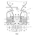
- FIG. 1 is a schematic configuration diagram of a fluidized bed furnace according to an embodiment of the present invention.
- FIG. 2 is a schematic configuration diagram of the flow heating test apparatus.
- FIG. 1 is a schematic configuration diagram of a fluidized bed furnace 1 according to an embodiment of the present invention.
- the fluidized bed furnace 1 illustrated in FIG. 1 is an internal circulation fluidized bed type fluidized bed furnace 1.
- the fluidized bed furnace 1 is not limited, and in addition to the internal circulating fluidized bed type, various known types such as a general bubbling fluidized bed type, a high speed fluidized bed type, and an external circulating fluidized bed type.
- the present invention can be applied to the fluidized bed furnace of.
- the fluidized bed furnace 1 includes a combustion container 10.
- partition walls 41 and 42 partitioning the lower part of the combustion container 10 into three types of cells 61, 62 and 63, a fluid medium 4 filled in the cells 61, 62 and 63, and the cells 61. , 62, and 63, the fluidizing gas supply device 7 that supplies the fluidizing gas 110 that causes the fluidizing medium 4 to flow forms the internal circulation fluidized bed 2.
- the inner lower part of the combustion container 10 has three types: a "combustion cell 61" located in the center, a “circulation cell 62" located outside the combustion cell 61, and a “heat collection cell 63" located outside the circulation cell 62. It is divided into cells.
- the first partition wall 41 partitions between the combustion cell 61 and the circulation cell 62.
- the lower end of the first partition wall 41 and the bottom of the combustion container 10 are separated from each other, and the fluidized medium 4 is allowed to move from the combustion cell 61 to the circulation cell 62 while passing under the first partition wall 41.
- the second partition wall 42 partitions the circulation cell 62 and the heat collection cell 63.
- the lower end of the second partition wall 42 and the bottom of the combustion container 10 are separated from each other, and the fluid medium 4 passing from the heat collecting cell 63 to under the first partition wall 41 and the second partition wall 42 to the combustion cell 61. Is allowed to move.
- the upper end of the second partition wall 42 is at or near the surface level of the fluidized medium 4 housed in the combustion vessel 10, and the fluidized medium 4 jumps from the circulation cell 62 over the second partition wall 42 to the heat collection cell 63. Movement is allowed.
- a fuel inlet 11 is provided above the combustion cell 61.
- the fuel 3 is quantitatively supplied to the fuel inlet 11 by a fuel supply device (not shown).
- the fuel 3 injected into the furnace from the fuel injection port 11 falls into the combustion cell 61.
- a secondary combustion gas supply port 12 for blowing in the secondary combustion gas 120 is provided near the fuel injection port 11.
- a tertiary combustion gas supply port 13 for blowing the tertiary combustion gas 130 is provided above the secondary combustion gas supply port 12.
- the heat collecting cell 63 is provided with a heat transfer tube 64 such as a superheater or an evaporator. Heat is recovered by the heat medium passing through the heat transfer tube 64.
- the fluidizing gas supply device 7 supplies the fluidizing gas 110 whose flow rate is independently adjusted to each of the combustion cell 61, the circulation cell 62, and the heat collecting cell 63.
- the bottom of the combustion container 10 is composed of a dispersion plate provided with a large number of pores.
- air boxes 71, 72, 73 are provided which communicate with the inside of the combustion container 10 through pores.
- the wind boxes 71, 72, 73 are provided corresponding to the cells 61, 62, 63.
- a high temperature fluidized gas 110 is pressure-fed to each of the air boxes 71, 72, 73 by a pressing fan (not shown).
- the flow rate of the fluidizing gas 110 supplied to each of the air boxes 71, 72, 73 may be adjusted by a valve or damper (not shown).
- each of the air boxes 71, 72, 72, 72, 72, so that the superficial velocity of the fluidizing gas 110 in each of the cells 61, 62, 63 has a predetermined correlation that causes a circulating flow in the fluidized medium 4.
- the flow rate of the fluidizing gas 110 supplied to 73 is adjusted.
- the "predetermined correlation" means that the superficial velocity of the fluidizing gas 110 in each cell 61, 62, 63 is higher than the fluidizing velocity of the fluidizing medium 4, and the fluidizing of the circulation cell 62 is performed.
- the superficial velocity of the gas 110 is higher than that of the fluidizing gas 110 in the combustion cell 61, and the superficial velocity of the fluidizing gas 110 in the combustion cell 61 is superficial to the fluidizing gas 110 in the heat collecting cell 63. It means a superficial velocity relationship of the fluidizing gas 110 in each cell 61, 62, 63 which is higher than the velocity.
- the fluidized medium 4 of the combustion cell 61 moves under the first partition wall 41 to the circulation cell 62, and the fluidized medium 4 of the circulation cell 62 passes over the second partition wall 42 and the heat collection cell 63. Then, the fluidized medium 4 of the heat collection cell 63 is circulated to the combustion cell 61 through the lower side of the first partition wall 41 and the second partition wall 42.
- low air ratio combustion is performed in the fluidized bed 2.
- combustible pyrolysis gas and pyrolysis residue are generated due to slow drying and pyrolysis of the fuel 3.
- the thermal decomposition residue and the unburned residue of the fuel 3 are discharged to the outside of the furnace from the fluidized medium 4 and the incombustibles outlet 15 provided at the bottom of the combustion cell 61.
- the fluidized gas 110 blown through the circulation cell 62 and the heat collection cell 63, and the pyrolysis gas generated in the circulation cell 62 and the heat collection cell 63 are blown out from the secondary combustion gas supply port 12 as the secondary combustion gas 120. ..
- the pyrolysis gas generated in the combustion cell 61 is combusted in the secondary combustion gas 120, the unburned components in the combustion gas are completely combusted in the tertiary combustion gas 130, and the combustion exhaust gas is discharged outside the furnace.
- the fluidized medium 4 is made of particulate minerals and/or particulate slag, and the content of quartz is 14% by mass or less.
- the above minerals are selected from the group consisting of garnet (garnet), ilmenite (FeTiO 3 ), olivine ((Mg,Fe) 2 SiO 4 ), and chromite ((Fe,Mg)Cr 2 O 4 ). May be at least one mineral. These minerals contain much less quartz than silica sand. Garnet is represented by the general formula A 3 B 2 (SiO 4 ) 3 or A 3 B 2 C 3 O 12 . The main components are calcium, magnesium, iron (II), manganese, etc. as A, iron (III), aluminum, chromium, titanium etc. as B, and silicon, aluminum, iron (III) etc. as C.
- the slag may be at least one slag selected from the group consisting of ferronickel slag and copper slag. These slags contain much less quartz than silica sand. Ferronickel slag is a residue generated when smelting ferronickel, which is a raw material for stainless steel and the like. Ferro nickel slag contains SiO 2 (silica) and MgO as main components. Copper slag is a residue generated when smelting copper. The copper slag has FeO, SiO 2 , CaO, and Al 2 O 3 as main components.
- the content of quartz in the fluidized medium 4 can be measured by an X-ray diffraction method. Quartz in the fluid medium 4 reacts with the alkali metal component in the fuel 3 to form an adhesive layer on the surface of the particles. As a result, the fluid medium 4 aggregates or agglomerates. When the content of quartz exceeds 14% by mass, the fluidization of the fluidized bed 2 is hindered by the agglomeration and agglomeration of the fluidized medium 4, and the stable combustion of the fuel 3 becomes difficult. When the content of quartz is 14% by mass or less, aggregation or agglomeration of the fluidized medium 4 does not occur or is small, and the fluidized bed 2 can maintain a good fluidity.
- the fluidized medium 4 may not contain quartz. From such a viewpoint, the content of quartz in the fluid medium 4 is set to 0 mass% or more and 14 mass% or less.
- the content of SiO 2 as an element of the fluidized medium 4 is not particularly limited.
- Sample 1 Garnet (Indian garnet sand (alumina-based almandite (Fe 3 Al 2 (SiO 4 ) 3 )), MAC Co., Ltd.), Sample 2: Ferronickel slag (NE Sand No. 6, Yamakawa Sangyo Co., Ltd.), Sample 3: Ilmenite (Ilmenite from Australia, Iwatani Corporation), Sample 4: Chromite (Chromite sand, Yamakawa Sangyo Co., Ltd.) Sample 5: olivine (olivine sand, Toho Olivine Industry Co., Ltd.), Comparative sample: Quartz sand (Bamboo folding sand No.5, Bamboo folding mill) Each sample was prepared.
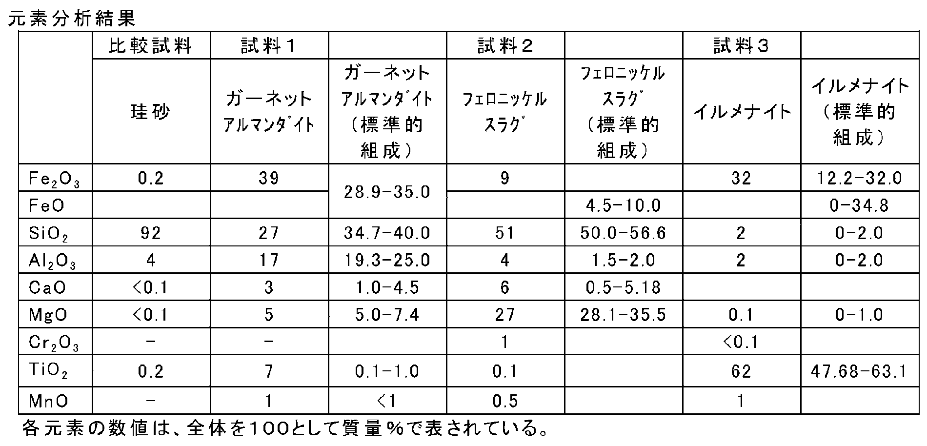
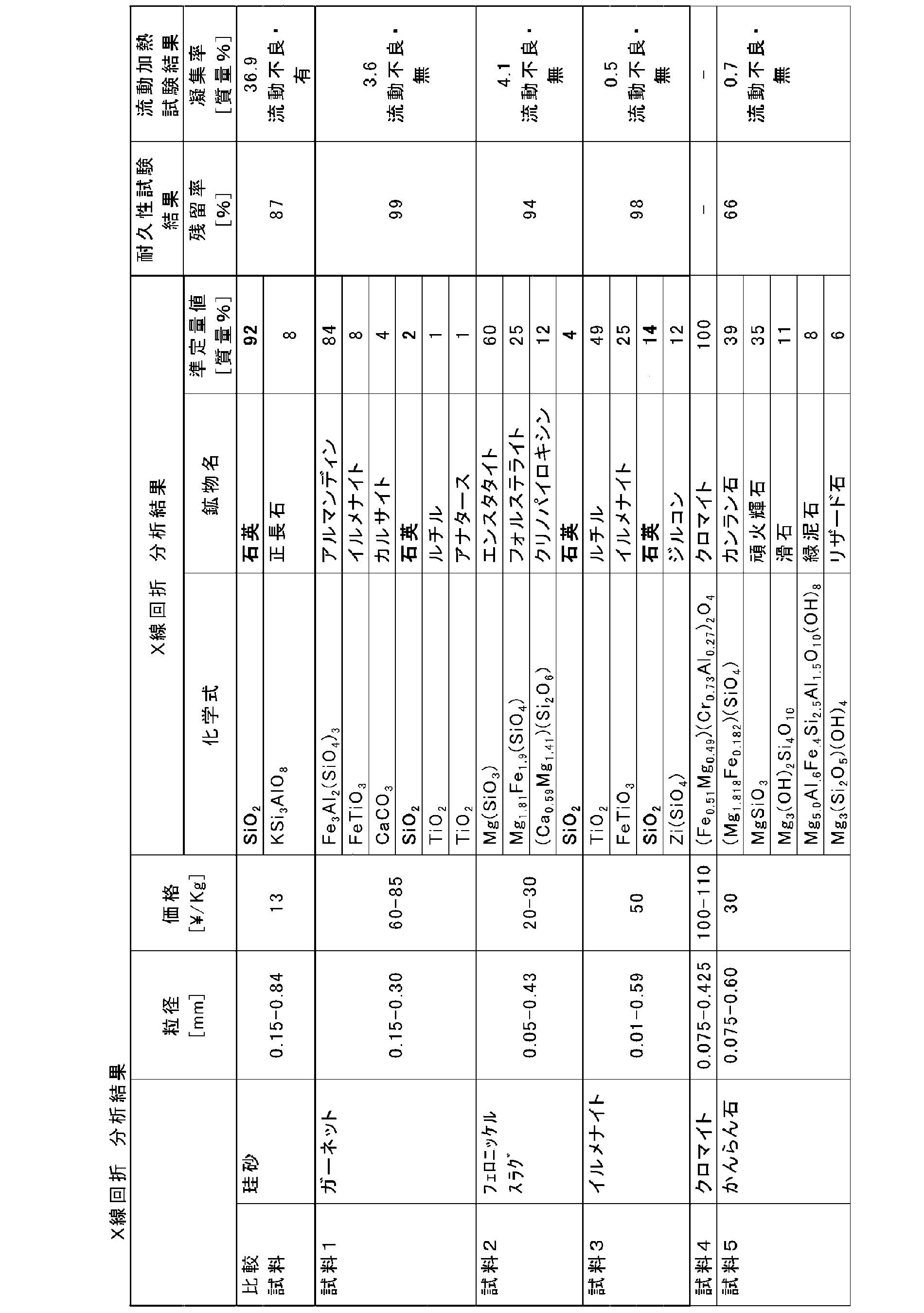
- Table 1 shows the elemental analysis results of Samples 1 to 3 and Comparative Sample. Table 1 also shows standard compositions of garnet (almandite), ferronickel slag, and ilmenite. Table 2 shows the prices of Samples 1 to 5 and the comparative sample, the X-ray diffraction analysis results, the durability test results, and the flow heating test results.
- silica sand of the comparative sample most of the contained SiO 2 is present as quartz.
- samples 1 to 3 contain SiO 2 , most of them do not exist as quartz, and the content of quartz is 14% by mass or less. Samples 4 and 5 contain almost no quartz.
- the prices of Samples 1 to 3 are suppressed to 10 times or less the price of silica sand.
- the price of aluminum oxide is more than 10 times the price of silica sand.
- the average particle diameter of the fluidized medium 4 is set in an appropriate range according to the flow velocity (target flow velocity) of the fluidized medium in the fluidized bed.
- Table 3 shows the relationship between the flow velocity and particle size of the fluidized medium in the fluidized bed for each of the internal circulating fluidized bed boiler (ICFB) and the circulating fluidized bed boiler (CFB).
- ICFB internal circulating fluidized bed boiler
- CFB circulating fluidized bed boiler
- a suitable average particle diameter of the fluidized medium 4 is, for example, assuming that the bed temperature of the fluidized bed is 550 to 1000° C. and the specific gravity of the fluidized medium 4 is 2.5 to 5.0. It can be calculated as a range from the minimum value to the maximum value of the particle diameter of 129 m/s or less.
- the average particle diameter of the fluidized medium 4 is generally within the range of 0.37 mm or more and 0.61 mm or less.
- the average particle size of the fluid medium (Sample 1) is preferably 0.48 mm.
- the average particle size of the fluid medium (Sample 2) is preferably 0.58 mm.
- the average particle size of the fluid medium (Sample 3) is preferably 0.44 mm.
- the average particle diameter of the fluid medium 4 may be measured by a sieving method. Specifically, it is sieved using a sieve specified in JIS Z 8801, the mass of the sample remaining on each sieve is measured, the cumulative distribution is described in the graph, and the cumulative distribution (particle size distribution) volume-based The particle diameter (d50) at which the relative particle amount is 50% is determined as the average particle diameter.
- FIG. 2 is a diagram showing a schematic configuration of the flow heating test apparatus 8.
- the fluid heating test apparatus 8 includes a SUS core tube 81, a tubular furnace 80 that heats the core tube 81, an Ar gas cylinder 82 and a PR gas cylinder 83 that are fluidizing gas sources, an air heater 84 that heats the fluidizing gas, and a core.
- a cyclone 88 for dust collection and a cold trap 89 provided in the exhaust gas system from the pipe 81 are provided.
- the core tube 81 is filled with a sample of the fluidized medium 4 so that the height of the stationary layer is 60 mm.
- the Ar gas supply amount from the Ar gas cylinder 82 is adjusted by the first mass flow controller 85, and the PR gas supply amount from the PR gas cylinder 83 is adjusted by the second mass flow controller 86.
- the fluidized-heat test apparatus 8 includes a first pressure sensor 91 that detects the pressure inside the fluidized bed 2, a second pressure sensor 92 that detects the outlet pressure of the core tube 81, and a temperature sensor 95 that detects the temperature of the fluidized bed 2. Further, a fluidized bed differential pressure gauge 94 for measuring a fluidized bed differential pressure ⁇ P2 which is a difference between the in-bed pressure of the fluidized bed 2 and the outlet pressure of the core tube 81 is further provided.
- the gas from the Ar gas cylinder 82 and the PR gas cylinder 83 are combined after being adjusted in flow rate by the mass flow controllers 85 and 86, and heated by the air heater 84 to 200° C. It flows into the bottom inlet of the core tube 81.
- the fluidized gas passes through the core tube 81 from the lower side to the upper side, whereby the fluidized medium 4 flows and the fluidized bed 2 is formed.
- the fluidized medium 4 which is broken into fine particles while flowing is scattered from the fluidized bed 2, passes through the freeboard layer, and is discharged from the core tube 81 along with the exhaust gas.
- the exhaust gas from the core tube 81 passes through the cyclone 88, where the fine fluidized medium that accompanies the exhaust gas is separated and collected.
- the exhaust gas that has passed through the cyclone 88 is cooled by the cold trap 89 and is diffused.
- the flow heating test is performed by the following procedures (1) to (6).
- (3) While ventilating with 2.0 NL/min of Ar gas, the temperature of the core tube 81 is raised in the tubular furnace 80. When the temperature in the fluidized bed 2 is around 750° C., the flow rate of Ar gas is adjusted so as to correspond to U/Umf 5.0.
- the temperature of the core tube 81 is lowered, and the conditions inside the core tube 81 (bridge due to aggregate formation, adhesion state inside tube, etc.) are confirmed. Further, the contents of the furnace core tube 81 are taken out, and each weight after classification is measured using a sieve having an opening of 500 ⁇ m.
- Table 2 shows the results of the flow heating test.
- the fluidized medium classified by a sieve to 500 ⁇ m or more was defined as “aggregated fluidized medium”, and the ratio [%] of the mass of the aggregated fluidized medium to the total mass of the initial fluidized medium was defined as the aggregation rate.
- Samples 1 to 3 and 5 all had a significantly lower agglomeration rate than silica sand as a comparative sample, and no fluidity failure in the fluidized bed 2 was observed.
- the fluid medium 4 preferably has a predetermined durability.
- the durability of the fluid medium 4 can be evaluated by the residual rate after fluidized heating.
- the criterion for the durability evaluation may be, for example, the durability of silica sand that has been generally used as a fluid medium.
- the durability test is conducted at the same time as the above-mentioned flow heating test. Specifically, in the flow heating test, the mass of the fluid medium collected by the cyclone 88 is measured. Then, the difference between the mass of the fluid medium filled in the core tube 81 at the start of the test and the mass of the fluid medium collected by the cyclone 88 is divided by the mass of the fluid medium filled in the core tube 81 at the start of the test, The value obtained by multiplying this by 100 is taken as the residual rate [%].
- Table 2 shows the results of the durability test. Samples 1 to 3 and 5 all had a higher residual rate than silica sand as a comparative sample. Therefore, it can be said that the samples 1 to 3 and 5 have a predetermined durability as a fluid medium.
Landscapes
- Engineering & Computer Science (AREA)
- Chemical & Material Sciences (AREA)
- Mechanical Engineering (AREA)
- General Engineering & Computer Science (AREA)
- Combustion & Propulsion (AREA)
- Chemical Kinetics & Catalysis (AREA)
- Environmental & Geological Engineering (AREA)
- Fluidized-Bed Combustion And Resonant Combustion (AREA)
Abstract
Description
試料2:フェロニッケルスラグ(NEサンド6号,山川産業株式会社)、
試料3:イルメナイト(豪州産イルメナイト,岩谷産業株式会社)、
試料4:クロマイト(クロマイトサンド、山川産業株式会社)
試料5:かんらん石(オリビンサンド,東邦オリビン工業株式会社)、
比較試料:珪砂(竹折硅砂5号,有限会社竹折砿業所)、
の各試料を用意した。表1には、試料1~3及び比較試料の元素分析結果を示す。なお、表1には、ガーネット(アルマンダイト)、フェロニッケルスラグ、及び、イルメナイトの標準的組成も併せて示す。また、表2に、試料1~5及び比較試料の価格、X線回折の分析結果、耐久性試験結果、及び流動加熱試験結果を示す。比較試料の珪砂では、含まれるSiO2の殆どが石英として存在している。一方、試料1~3にはSiO2が含まれるものの、その殆どが石英として存在せず、石英の含有量が14質量%以下である。試料4,5には石英が殆ど含まれない。また、試料1~3の価格は、珪砂の価格の10倍以下に抑えられている。なお、酸化アルミニウムの価格は、珪砂の価格の10倍以上である。

ここで、流動媒体4の凝集抑制効果を評価するための、流動加熱試験について説明する。
(1)11.5gの模擬灰(K2CO3)を測り取り、流動層2中の模擬灰体積濃度が0.117g/mLとなるように、ビーカー内で流動媒体の試料と模擬灰とを混合する。
(2)炉心管81に、初期静止層高が60mmとなるように、試料と模擬灰との混合物を充填する。
(3)2.0NL/minのArガスで通気しながら、管状炉80で炉心管81を昇温させる。流動層2内の温度が750℃付近になれば、Arガスの流量をU/Umf=5.0相当となるように調整する。
(4)流動層2内の温度が750℃に安定してから、ArガスにPRガス(CH4 10%+ArベースのProportional Gas)を添加することにより、CH4濃度が4%となるように調整して、試験を開始する。
(5)流動媒体が凝集して流動しなくなると、流動層差圧ΔP1が低下する。そこで、流動層差圧ΔP1の変化を波形チャートに基づいて観察し、流動層差圧ΔP1が急激に減少した時点で試験を終了する。流動層差圧ΔP1の急激な変化が観察されない場合には、5時間で試験を終了する。
(6)試験終了後、炉心管81を降温し、炉心管81内の状況(凝集物生成によるブリッジ、管内付着状況等)を確認する。更に、炉心管81の内容物を取り出し、目開き500μmの篩を用いて、分級後の各重量を測定する。
流動媒体4は、所定の耐久性を備えることが好ましい。流動媒体4の耐久性は、流動加熱後の残留率で評価することができる。耐久性の評価の基準は、例えば、一般的に流動媒体として使用されてきた珪砂の耐久性としてよい。
2 :流動層
3 :燃料
4 :流動媒体
7 :流動化ガス供給装置
8 :流動加熱試験装置
10 :燃焼容器
11 :燃料投入口
12 :二次燃焼ガス供給口
13 :三次燃焼ガス供給口
15 :抜出口
41,42 :仕切壁
61 :燃焼セル
62 :循環セル
63 :収熱セル
64 :伝熱管
71,72,73 :風箱
80 :管状炉
81 :炉心管
82 :Arガスボンベ
83 :PRガスボンベ
84 :エアヒータ
85,86 :マスフローコントローラ
88 :サイクロン
89 :コールドトラップ
91,92 :圧力センサ
94 :流動層差圧計
95 :温度センサ
110:流動化ガス
120:二次燃焼ガス
130:三次燃焼ガス
Claims (3)
- 流動媒体を流動させて供給された燃料を燃焼する流動層を備え、
前記燃料は、アルカリ金属を含有し、
前記流動媒体は、粒子状鉱物及び/又は粒子状スラグからなり、石英の含有量が14質量%以下である、
流動床炉。 - 前記鉱物が、ガーネット、イルメナイト、かんらん石、及び、クロマイトよりなる群から選択される少なくとも1種の鉱物である、
請求項1に記載の流動床炉。 - 前記スラグが、フェロニッケルスラグ、及び、銅スラグよりなる群から選択される少なくとも1種のスラグである、
請求項1又は2に記載の流動床炉。
Priority Applications (3)
| Application Number | Priority Date | Filing Date | Title |
|---|---|---|---|
| MYPI2021003566A MY208744A (en) | 2018-12-28 | 2019-12-27 | Fluidized bed furnace |
| CN201980086088.4A CN113227652A (zh) | 2018-12-28 | 2019-12-27 | 流化床炉 |
| BR112021012320-2A BR112021012320B1 (pt) | 2018-12-28 | 2019-12-27 | Forno de leito fluidizado |
Applications Claiming Priority (2)
| Application Number | Priority Date | Filing Date | Title |
|---|---|---|---|
| JP2018247383A JP7251978B2 (ja) | 2018-12-28 | 2018-12-28 | 流動床炉 |
| JP2018-247383 | 2018-12-28 |
Publications (1)
| Publication Number | Publication Date |
|---|---|
| WO2020138484A1 true WO2020138484A1 (ja) | 2020-07-02 |
Family
ID=71126012
Family Applications (1)
| Application Number | Title | Priority Date | Filing Date |
|---|---|---|---|
| PCT/JP2019/051575 Ceased WO2020138484A1 (ja) | 2018-12-28 | 2019-12-27 | 流動床炉 |
Country Status (4)
| Country | Link |
|---|---|
| JP (1) | JP7251978B2 (ja) |
| CN (1) | CN113227652A (ja) |
| MY (1) | MY208744A (ja) |
| WO (1) | WO2020138484A1 (ja) |
Cited By (2)
| Publication number | Priority date | Publication date | Assignee | Title |
|---|---|---|---|---|
| CN111425870A (zh) * | 2020-04-28 | 2020-07-17 | 中国矿业大学 | 一种蓄热体循环式低浓度含瓦斯气体流态化协同氧化装置及协同氧化方法 |
| CN115337874A (zh) * | 2022-09-15 | 2022-11-15 | 南京理工大学 | 一种金属燃料颗粒流化床破膜反应方法 |
Families Citing this family (1)
| Publication number | Priority date | Publication date | Assignee | Title |
|---|---|---|---|---|
| JP2023145187A (ja) * | 2022-03-28 | 2023-10-11 | 一般財団法人カーボンフロンティア機構 | 燃焼装置、燃焼方法、ガス化装置、およびガス化方法 |
Citations (7)
| Publication number | Priority date | Publication date | Assignee | Title |
|---|---|---|---|---|
| JPS547779A (en) * | 1977-06-20 | 1979-01-20 | Energy Products Of Idaho | Cineration pyrolytic gasifying system |
| JPH0433817U (ja) * | 1990-06-29 | 1992-03-19 | ||
| US6460472B1 (en) * | 1998-04-30 | 2002-10-08 | Kvaerner Pulping Oy | Fluidized bed material, method for its production, and method in a fluidized bed process |
| JP2005068297A (ja) * | 2003-08-25 | 2005-03-17 | Ebara Corp | ガス生成装置及びガス生成方法 |
| JP2005226930A (ja) * | 2004-02-13 | 2005-08-25 | Kawasaki Heavy Ind Ltd | バイオマス燃料焚き流動層燃焼方法及びその装置 |
| WO2011007618A1 (ja) * | 2009-07-13 | 2011-01-20 | 住友重機械工業株式会社 | 流動床式ボイラの燃焼方法、及び流動床式ボイラ |
| US20180038586A1 (en) * | 2014-12-22 | 2018-02-08 | Improbed Ab | Bed material for bubbling fluidised bed combustion |
Family Cites Families (2)
| Publication number | Priority date | Publication date | Assignee | Title |
|---|---|---|---|---|
| JP2017071692A (ja) | 2015-10-07 | 2017-04-13 | Jfeスチール株式会社 | 炭素質燃料のガス化方法、製鉄所の操業方法およびガス化ガスの製造方法 |
| JP6406222B2 (ja) | 2015-11-17 | 2018-10-17 | Jfeスチール株式会社 | 炭素質燃料のガス化方法、製鉄所の操業方法およびガス化ガスの製造方法 |
-
2018
- 2018-12-28 JP JP2018247383A patent/JP7251978B2/ja active Active
-
2019
- 2019-12-27 MY MYPI2021003566A patent/MY208744A/en unknown
- 2019-12-27 WO PCT/JP2019/051575 patent/WO2020138484A1/ja not_active Ceased
- 2019-12-27 CN CN201980086088.4A patent/CN113227652A/zh active Pending
Patent Citations (7)
| Publication number | Priority date | Publication date | Assignee | Title |
|---|---|---|---|---|
| JPS547779A (en) * | 1977-06-20 | 1979-01-20 | Energy Products Of Idaho | Cineration pyrolytic gasifying system |
| JPH0433817U (ja) * | 1990-06-29 | 1992-03-19 | ||
| US6460472B1 (en) * | 1998-04-30 | 2002-10-08 | Kvaerner Pulping Oy | Fluidized bed material, method for its production, and method in a fluidized bed process |
| JP2005068297A (ja) * | 2003-08-25 | 2005-03-17 | Ebara Corp | ガス生成装置及びガス生成方法 |
| JP2005226930A (ja) * | 2004-02-13 | 2005-08-25 | Kawasaki Heavy Ind Ltd | バイオマス燃料焚き流動層燃焼方法及びその装置 |
| WO2011007618A1 (ja) * | 2009-07-13 | 2011-01-20 | 住友重機械工業株式会社 | 流動床式ボイラの燃焼方法、及び流動床式ボイラ |
| US20180038586A1 (en) * | 2014-12-22 | 2018-02-08 | Improbed Ab | Bed material for bubbling fluidised bed combustion |
Cited By (2)
| Publication number | Priority date | Publication date | Assignee | Title |
|---|---|---|---|---|
| CN111425870A (zh) * | 2020-04-28 | 2020-07-17 | 中国矿业大学 | 一种蓄热体循环式低浓度含瓦斯气体流态化协同氧化装置及协同氧化方法 |
| CN115337874A (zh) * | 2022-09-15 | 2022-11-15 | 南京理工大学 | 一种金属燃料颗粒流化床破膜反应方法 |
Also Published As
| Publication number | Publication date |
|---|---|
| BR112021012320A2 (pt) | 2021-09-08 |
| JP2020106244A (ja) | 2020-07-09 |
| CN113227652A (zh) | 2021-08-06 |
| MY208744A (en) | 2025-05-27 |
| JP7251978B2 (ja) | 2023-04-04 |
Similar Documents
| Publication | Publication Date | Title |
|---|---|---|
| Salour et al. | Control of in-bed agglomeration by fuel blending in a pilot scale straw and wood fueled AFBC | |
| Wang et al. | Understanding ash deposition for Zhundong coal combustion in 330 MW utility boiler: Focusing on surface temperature effects | |
| Elled et al. | Composition of agglomerates in fluidized bed reactors for thermochemical conversion of biomass and waste fuels: Experimental data in comparison with predictions by a thermodynamic equilibrium model | |
| Olofsson et al. | Bed agglomeration problems in fluidized-bed biomass combustion | |
| Han et al. | Effects of torrefaction on ash-related issues during biomass combustion and co-combustion with coal. Part 3: Ash slagging behavior | |
| Liu et al. | Ash deposition behavior of a high-alkali coal in circulating fluidized bed combustion at different bed temperatures and the effect of kaolin | |
| Nguyen et al. | Ash characteristics of oxy-biomass combustion in a circulating fluidized bed with kaolin addition | |
| Zi et al. | Slagging behavior and mechanism of high-sodium–chlorine coal combustion in a full-scale circulating fluidized bed boiler | |
| JP7251978B2 (ja) | 流動床炉 | |
| Ji et al. | Xinjiang lignite ash slagging and flow under the weak reducing environment at 1300° C–Release of sodium out of slag and its modelling from the mass transfer perspective | |
| Sweeten et al. | Combustion of cattle feedlot manure for energy production | |
| Li et al. | Investigation on formation mechanisms of ash and deposit from cotton stalk vibrating grate boiler combustion based on their characteristics | |
| Sun et al. | Experimental study on cotton stalk combustion in a circulating fluidized bed | |
| CN111133253B (zh) | 流化床用流化介质 | |
| CN108483445A (zh) | 一种循环床活性炭活化系统 | |
| US2509866A (en) | Low-temperature combustion and apparatus therefor | |
| CN109022006B (zh) | 煤粉粒径分级利用的粉状焦炭/兰炭的生产系统及工艺 | |
| CN1970698A (zh) | 一种降低煤灰熔点的助熔剂及其制备方法 | |
| Namkung et al. | Effect of bed agglomeration by mineral component with different coal types | |
| JP2986717B2 (ja) | 微粉炭の搬送性向上方法 | |
| JP2023074185A (ja) | 流動層装置 | |
| Namkung et al. | Coal fouling characteristic to deposit probe with different temperatures under the gasification condition | |
| BR112021012320B1 (pt) | Forno de leito fluidizado | |
| CN107726307A (zh) | 一种cfb锅炉掺烧石油焦的工艺 | |
| EP1075626A1 (en) | Fluidized bed material, method for its production, and method in a fluidized bed process |
Legal Events
| Date | Code | Title | Description |
|---|---|---|---|
| 121 | Ep: the epo has been informed by wipo that ep was designated in this application |
Ref document number: 19905350 Country of ref document: EP Kind code of ref document: A1 |
|
| NENP | Non-entry into the national phase |
Ref country code: DE |
|
| REG | Reference to national code |
Ref country code: BR Ref legal event code: B01A Ref document number: 112021012320 Country of ref document: BR |
|
| ENP | Entry into the national phase |
Ref document number: 112021012320 Country of ref document: BR Kind code of ref document: A2 Effective date: 20210622 |
|
| 122 | Ep: pct application non-entry in european phase |
Ref document number: 19905350 Country of ref document: EP Kind code of ref document: A1 |