WO2020138477A2 - Conductive paste for forming stretchable conductor, stretchable conductor layer, method for producing stretchable conductor layer, stretchable electrical wiring structure, and biometric information measuring device - Google Patents
Conductive paste for forming stretchable conductor, stretchable conductor layer, method for producing stretchable conductor layer, stretchable electrical wiring structure, and biometric information measuring device Download PDFInfo
- Publication number
- WO2020138477A2 WO2020138477A2 PCT/JP2019/051558 JP2019051558W WO2020138477A2 WO 2020138477 A2 WO2020138477 A2 WO 2020138477A2 JP 2019051558 W JP2019051558 W JP 2019051558W WO 2020138477 A2 WO2020138477 A2 WO 2020138477A2
- Authority
- WO
- WIPO (PCT)
- Prior art keywords
- stretchable
- mass
- layer
- conductive
- electrical wiring
- Prior art date
Links
Images


Classifications
-
- A—HUMAN NECESSITIES
- A61—MEDICAL OR VETERINARY SCIENCE; HYGIENE
- A61B—DIAGNOSIS; SURGERY; IDENTIFICATION
- A61B5/00—Measuring for diagnostic purposes; Identification of persons
- A61B5/24—Detecting, measuring or recording bioelectric or biomagnetic signals of the body or parts thereof
- A61B5/25—Bioelectric electrodes therefor
- A61B5/251—Means for maintaining electrode contact with the body
- A61B5/256—Wearable electrodes, e.g. having straps or bands
-
- H—ELECTRICITY
- H01—ELECTRIC ELEMENTS
- H01B—CABLES; CONDUCTORS; INSULATORS; SELECTION OF MATERIALS FOR THEIR CONDUCTIVE, INSULATING OR DIELECTRIC PROPERTIES
- H01B1/00—Conductors or conductive bodies characterised by the conductive materials; Selection of materials as conductors
- H01B1/20—Conductive material dispersed in non-conductive organic material
-
- A—HUMAN NECESSITIES
- A61—MEDICAL OR VETERINARY SCIENCE; HYGIENE
- A61B—DIAGNOSIS; SURGERY; IDENTIFICATION
- A61B5/00—Measuring for diagnostic purposes; Identification of persons
- A61B5/24—Detecting, measuring or recording bioelectric or biomagnetic signals of the body or parts thereof
- A61B5/25—Bioelectric electrodes therefor
- A61B5/263—Bioelectric electrodes therefor characterised by the electrode materials
- A61B5/266—Bioelectric electrodes therefor characterised by the electrode materials containing electrolytes, conductive gels or pastes
-
- A—HUMAN NECESSITIES
- A61—MEDICAL OR VETERINARY SCIENCE; HYGIENE
- A61B—DIAGNOSIS; SURGERY; IDENTIFICATION
- A61B5/00—Measuring for diagnostic purposes; Identification of persons
- A61B5/24—Detecting, measuring or recording bioelectric or biomagnetic signals of the body or parts thereof
- A61B5/25—Bioelectric electrodes therefor
- A61B5/279—Bioelectric electrodes therefor specially adapted for particular uses
- A61B5/28—Bioelectric electrodes therefor specially adapted for particular uses for electrocardiography [ECG]
-
- A—HUMAN NECESSITIES
- A61—MEDICAL OR VETERINARY SCIENCE; HYGIENE
- A61B—DIAGNOSIS; SURGERY; IDENTIFICATION
- A61B5/00—Measuring for diagnostic purposes; Identification of persons
- A61B5/24—Detecting, measuring or recording bioelectric or biomagnetic signals of the body or parts thereof
- A61B5/25—Bioelectric electrodes therefor
- A61B5/279—Bioelectric electrodes therefor specially adapted for particular uses
- A61B5/291—Bioelectric electrodes therefor specially adapted for particular uses for electroencephalography [EEG]
-
- A—HUMAN NECESSITIES
- A61—MEDICAL OR VETERINARY SCIENCE; HYGIENE
- A61B—DIAGNOSIS; SURGERY; IDENTIFICATION
- A61B5/00—Measuring for diagnostic purposes; Identification of persons
- A61B5/68—Arrangements of detecting, measuring or recording means, e.g. sensors, in relation to patient
- A61B5/6801—Arrangements of detecting, measuring or recording means, e.g. sensors, in relation to patient specially adapted to be attached to or worn on the body surface
- A61B5/6802—Sensor mounted on worn items
- A61B5/6804—Garments; Clothes
- A61B5/6805—Vests
-
- B—PERFORMING OPERATIONS; TRANSPORTING
- B32—LAYERED PRODUCTS
- B32B—LAYERED PRODUCTS, i.e. PRODUCTS BUILT-UP OF STRATA OF FLAT OR NON-FLAT, e.g. CELLULAR OR HONEYCOMB, FORM
- B32B7/00—Layered products characterised by the relation between layers; Layered products characterised by the relative orientation of features between layers, or by the relative values of a measurable parameter between layers, i.e. products comprising layers having different physical, chemical or physicochemical properties; Layered products characterised by the interconnection of layers
- B32B7/02—Physical, chemical or physicochemical properties
- B32B7/025—Electric or magnetic properties
-
- C—CHEMISTRY; METALLURGY
- C08—ORGANIC MACROMOLECULAR COMPOUNDS; THEIR PREPARATION OR CHEMICAL WORKING-UP; COMPOSITIONS BASED THEREON
- C08G—MACROMOLECULAR COMPOUNDS OBTAINED OTHERWISE THAN BY REACTIONS ONLY INVOLVING UNSATURATED CARBON-TO-CARBON BONDS
- C08G18/00—Polymeric products of isocyanates or isothiocyanates
- C08G18/06—Polymeric products of isocyanates or isothiocyanates with compounds having active hydrogen
- C08G18/28—Polymeric products of isocyanates or isothiocyanates with compounds having active hydrogen characterised by the compounds used containing active hydrogen
- C08G18/30—Low-molecular-weight compounds
- C08G18/32—Polyhydroxy compounds; Polyamines; Hydroxyamines
- C08G18/3203—Polyhydroxy compounds
- C08G18/3206—Polyhydroxy compounds aliphatic
-
- C—CHEMISTRY; METALLURGY
- C08—ORGANIC MACROMOLECULAR COMPOUNDS; THEIR PREPARATION OR CHEMICAL WORKING-UP; COMPOSITIONS BASED THEREON
- C08G—MACROMOLECULAR COMPOUNDS OBTAINED OTHERWISE THAN BY REACTIONS ONLY INVOLVING UNSATURATED CARBON-TO-CARBON BONDS
- C08G18/00—Polymeric products of isocyanates or isothiocyanates
- C08G18/06—Polymeric products of isocyanates or isothiocyanates with compounds having active hydrogen
- C08G18/28—Polymeric products of isocyanates or isothiocyanates with compounds having active hydrogen characterised by the compounds used containing active hydrogen
- C08G18/40—High-molecular-weight compounds
- C08G18/42—Polycondensates having carboxylic or carbonic ester groups in the main chain
- C08G18/4202—Two or more polyesters of different physical or chemical nature
-
- C—CHEMISTRY; METALLURGY
- C08—ORGANIC MACROMOLECULAR COMPOUNDS; THEIR PREPARATION OR CHEMICAL WORKING-UP; COMPOSITIONS BASED THEREON
- C08G—MACROMOLECULAR COMPOUNDS OBTAINED OTHERWISE THAN BY REACTIONS ONLY INVOLVING UNSATURATED CARBON-TO-CARBON BONDS
- C08G18/00—Polymeric products of isocyanates or isothiocyanates
- C08G18/06—Polymeric products of isocyanates or isothiocyanates with compounds having active hydrogen
- C08G18/28—Polymeric products of isocyanates or isothiocyanates with compounds having active hydrogen characterised by the compounds used containing active hydrogen
- C08G18/40—High-molecular-weight compounds
- C08G18/42—Polycondensates having carboxylic or carbonic ester groups in the main chain
- C08G18/4205—Polycondensates having carboxylic or carbonic ester groups in the main chain containing cyclic groups
- C08G18/4208—Polycondensates having carboxylic or carbonic ester groups in the main chain containing cyclic groups containing aromatic groups
- C08G18/4211—Polycondensates having carboxylic or carbonic ester groups in the main chain containing cyclic groups containing aromatic groups derived from aromatic dicarboxylic acids and dialcohols
- C08G18/4216—Polycondensates having carboxylic or carbonic ester groups in the main chain containing cyclic groups containing aromatic groups derived from aromatic dicarboxylic acids and dialcohols from mixtures or combinations of aromatic dicarboxylic acids and aliphatic dicarboxylic acids and dialcohols
-
- C—CHEMISTRY; METALLURGY
- C08—ORGANIC MACROMOLECULAR COMPOUNDS; THEIR PREPARATION OR CHEMICAL WORKING-UP; COMPOSITIONS BASED THEREON
- C08G—MACROMOLECULAR COMPOUNDS OBTAINED OTHERWISE THAN BY REACTIONS ONLY INVOLVING UNSATURATED CARBON-TO-CARBON BONDS
- C08G18/00—Polymeric products of isocyanates or isothiocyanates
- C08G18/06—Polymeric products of isocyanates or isothiocyanates with compounds having active hydrogen
- C08G18/28—Polymeric products of isocyanates or isothiocyanates with compounds having active hydrogen characterised by the compounds used containing active hydrogen
- C08G18/40—High-molecular-weight compounds
- C08G18/42—Polycondensates having carboxylic or carbonic ester groups in the main chain
- C08G18/4236—Polycondensates having carboxylic or carbonic ester groups in the main chain containing only aliphatic groups
- C08G18/4238—Polycondensates having carboxylic or carbonic ester groups in the main chain containing only aliphatic groups derived from dicarboxylic acids and dialcohols
-
- C—CHEMISTRY; METALLURGY
- C08—ORGANIC MACROMOLECULAR COMPOUNDS; THEIR PREPARATION OR CHEMICAL WORKING-UP; COMPOSITIONS BASED THEREON
- C08G—MACROMOLECULAR COMPOUNDS OBTAINED OTHERWISE THAN BY REACTIONS ONLY INVOLVING UNSATURATED CARBON-TO-CARBON BONDS
- C08G18/00—Polymeric products of isocyanates or isothiocyanates
- C08G18/06—Polymeric products of isocyanates or isothiocyanates with compounds having active hydrogen
- C08G18/28—Polymeric products of isocyanates or isothiocyanates with compounds having active hydrogen characterised by the compounds used containing active hydrogen
- C08G18/65—Low-molecular-weight compounds having active hydrogen with high-molecular-weight compounds having active hydrogen
- C08G18/66—Compounds of groups C08G18/42, C08G18/48, or C08G18/52
- C08G18/6633—Compounds of group C08G18/42
- C08G18/6637—Compounds of group C08G18/42 with compounds of group C08G18/32 or polyamines of C08G18/38
- C08G18/664—Compounds of group C08G18/42 with compounds of group C08G18/32 or polyamines of C08G18/38 with compounds of group C08G18/3203
-
- C—CHEMISTRY; METALLURGY
- C08—ORGANIC MACROMOLECULAR COMPOUNDS; THEIR PREPARATION OR CHEMICAL WORKING-UP; COMPOSITIONS BASED THEREON
- C08G—MACROMOLECULAR COMPOUNDS OBTAINED OTHERWISE THAN BY REACTIONS ONLY INVOLVING UNSATURATED CARBON-TO-CARBON BONDS
- C08G18/00—Polymeric products of isocyanates or isothiocyanates
- C08G18/06—Polymeric products of isocyanates or isothiocyanates with compounds having active hydrogen
- C08G18/70—Polymeric products of isocyanates or isothiocyanates with compounds having active hydrogen characterised by the isocyanates or isothiocyanates used
- C08G18/72—Polyisocyanates or polyisothiocyanates
- C08G18/74—Polyisocyanates or polyisothiocyanates cyclic
- C08G18/75—Polyisocyanates or polyisothiocyanates cyclic cycloaliphatic
- C08G18/751—Polyisocyanates or polyisothiocyanates cyclic cycloaliphatic containing only one cycloaliphatic ring
- C08G18/752—Polyisocyanates or polyisothiocyanates cyclic cycloaliphatic containing only one cycloaliphatic ring containing at least one isocyanate or isothiocyanate group linked to the cycloaliphatic ring by means of an aliphatic group
- C08G18/753—Polyisocyanates or polyisothiocyanates cyclic cycloaliphatic containing only one cycloaliphatic ring containing at least one isocyanate or isothiocyanate group linked to the cycloaliphatic ring by means of an aliphatic group containing one isocyanate or isothiocyanate group linked to the cycloaliphatic ring by means of an aliphatic group having a primary carbon atom next to the isocyanate or isothiocyanate group
- C08G18/755—Polyisocyanates or polyisothiocyanates cyclic cycloaliphatic containing only one cycloaliphatic ring containing at least one isocyanate or isothiocyanate group linked to the cycloaliphatic ring by means of an aliphatic group containing one isocyanate or isothiocyanate group linked to the cycloaliphatic ring by means of an aliphatic group having a primary carbon atom next to the isocyanate or isothiocyanate group and at least one isocyanate or isothiocyanate group linked to a secondary carbon atom of the cycloaliphatic ring, e.g. isophorone diisocyanate
-
- C—CHEMISTRY; METALLURGY
- C08—ORGANIC MACROMOLECULAR COMPOUNDS; THEIR PREPARATION OR CHEMICAL WORKING-UP; COMPOSITIONS BASED THEREON
- C08G—MACROMOLECULAR COMPOUNDS OBTAINED OTHERWISE THAN BY REACTIONS ONLY INVOLVING UNSATURATED CARBON-TO-CARBON BONDS
- C08G18/00—Polymeric products of isocyanates or isothiocyanates
- C08G18/06—Polymeric products of isocyanates or isothiocyanates with compounds having active hydrogen
- C08G18/70—Polymeric products of isocyanates or isothiocyanates with compounds having active hydrogen characterised by the isocyanates or isothiocyanates used
- C08G18/72—Polyisocyanates or polyisothiocyanates
- C08G18/74—Polyisocyanates or polyisothiocyanates cyclic
- C08G18/76—Polyisocyanates or polyisothiocyanates cyclic aromatic
- C08G18/7657—Polyisocyanates or polyisothiocyanates cyclic aromatic containing two or more aromatic rings
- C08G18/7664—Polyisocyanates or polyisothiocyanates cyclic aromatic containing two or more aromatic rings containing alkylene polyphenyl groups
- C08G18/7671—Polyisocyanates or polyisothiocyanates cyclic aromatic containing two or more aromatic rings containing alkylene polyphenyl groups containing only one alkylene bisphenyl group
-
- C—CHEMISTRY; METALLURGY
- C08—ORGANIC MACROMOLECULAR COMPOUNDS; THEIR PREPARATION OR CHEMICAL WORKING-UP; COMPOSITIONS BASED THEREON
- C08L—COMPOSITIONS OF MACROMOLECULAR COMPOUNDS
- C08L75/00—Compositions of polyureas or polyurethanes; Compositions of derivatives of such polymers
- C08L75/04—Polyurethanes
- C08L75/06—Polyurethanes from polyesters
-
- C—CHEMISTRY; METALLURGY
- C09—DYES; PAINTS; POLISHES; NATURAL RESINS; ADHESIVES; COMPOSITIONS NOT OTHERWISE PROVIDED FOR; APPLICATIONS OF MATERIALS NOT OTHERWISE PROVIDED FOR
- C09D—COATING COMPOSITIONS, e.g. PAINTS, VARNISHES OR LACQUERS; FILLING PASTES; CHEMICAL PAINT OR INK REMOVERS; INKS; CORRECTING FLUIDS; WOODSTAINS; PASTES OR SOLIDS FOR COLOURING OR PRINTING; USE OF MATERIALS THEREFOR
- C09D11/00—Inks
- C09D11/02—Printing inks
- C09D11/10—Printing inks based on artificial resins
- C09D11/102—Printing inks based on artificial resins containing macromolecular compounds obtained by reactions other than those only involving unsaturated carbon-to-carbon bonds
-
- C—CHEMISTRY; METALLURGY
- C09—DYES; PAINTS; POLISHES; NATURAL RESINS; ADHESIVES; COMPOSITIONS NOT OTHERWISE PROVIDED FOR; APPLICATIONS OF MATERIALS NOT OTHERWISE PROVIDED FOR
- C09D—COATING COMPOSITIONS, e.g. PAINTS, VARNISHES OR LACQUERS; FILLING PASTES; CHEMICAL PAINT OR INK REMOVERS; INKS; CORRECTING FLUIDS; WOODSTAINS; PASTES OR SOLIDS FOR COLOURING OR PRINTING; USE OF MATERIALS THEREFOR
- C09D11/00—Inks
- C09D11/52—Electrically conductive inks
-
- C—CHEMISTRY; METALLURGY
- C09—DYES; PAINTS; POLISHES; NATURAL RESINS; ADHESIVES; COMPOSITIONS NOT OTHERWISE PROVIDED FOR; APPLICATIONS OF MATERIALS NOT OTHERWISE PROVIDED FOR
- C09D—COATING COMPOSITIONS, e.g. PAINTS, VARNISHES OR LACQUERS; FILLING PASTES; CHEMICAL PAINT OR INK REMOVERS; INKS; CORRECTING FLUIDS; WOODSTAINS; PASTES OR SOLIDS FOR COLOURING OR PRINTING; USE OF MATERIALS THEREFOR
- C09D175/00—Coating compositions based on polyureas or polyurethanes; Coating compositions based on derivatives of such polymers
- C09D175/04—Polyurethanes
- C09D175/06—Polyurethanes from polyesters
-
- C—CHEMISTRY; METALLURGY
- C09—DYES; PAINTS; POLISHES; NATURAL RESINS; ADHESIVES; COMPOSITIONS NOT OTHERWISE PROVIDED FOR; APPLICATIONS OF MATERIALS NOT OTHERWISE PROVIDED FOR
- C09D—COATING COMPOSITIONS, e.g. PAINTS, VARNISHES OR LACQUERS; FILLING PASTES; CHEMICAL PAINT OR INK REMOVERS; INKS; CORRECTING FLUIDS; WOODSTAINS; PASTES OR SOLIDS FOR COLOURING OR PRINTING; USE OF MATERIALS THEREFOR
- C09D5/00—Coating compositions, e.g. paints, varnishes or lacquers, characterised by their physical nature or the effects produced; Filling pastes
- C09D5/24—Electrically-conducting paints
-
- H—ELECTRICITY
- H01—ELECTRIC ELEMENTS
- H01B—CABLES; CONDUCTORS; INSULATORS; SELECTION OF MATERIALS FOR THEIR CONDUCTIVE, INSULATING OR DIELECTRIC PROPERTIES
- H01B1/00—Conductors or conductive bodies characterised by the conductive materials; Selection of materials as conductors
- H01B1/20—Conductive material dispersed in non-conductive organic material
- H01B1/22—Conductive material dispersed in non-conductive organic material the conductive material comprising metals or alloys
-
- H—ELECTRICITY
- H01—ELECTRIC ELEMENTS
- H01B—CABLES; CONDUCTORS; INSULATORS; SELECTION OF MATERIALS FOR THEIR CONDUCTIVE, INSULATING OR DIELECTRIC PROPERTIES
- H01B13/00—Apparatus or processes specially adapted for manufacturing conductors or cables
- H01B13/0026—Apparatus for manufacturing conducting or semi-conducting layers, e.g. deposition of metal
-
- H—ELECTRICITY
- H01—ELECTRIC ELEMENTS
- H01B—CABLES; CONDUCTORS; INSULATORS; SELECTION OF MATERIALS FOR THEIR CONDUCTIVE, INSULATING OR DIELECTRIC PROPERTIES
- H01B5/00—Non-insulated conductors or conductive bodies characterised by their form
- H01B5/14—Non-insulated conductors or conductive bodies characterised by their form comprising conductive layers or films on insulating-supports
-
- H—ELECTRICITY
- H01—ELECTRIC ELEMENTS
- H01B—CABLES; CONDUCTORS; INSULATORS; SELECTION OF MATERIALS FOR THEIR CONDUCTIVE, INSULATING OR DIELECTRIC PROPERTIES
- H01B7/00—Insulated conductors or cables characterised by their form
- H01B7/06—Extensible conductors or cables, e.g. self-coiling cords
-
- H—ELECTRICITY
- H05—ELECTRIC TECHNIQUES NOT OTHERWISE PROVIDED FOR
- H05K—PRINTED CIRCUITS; CASINGS OR CONSTRUCTIONAL DETAILS OF ELECTRIC APPARATUS; MANUFACTURE OF ASSEMBLAGES OF ELECTRICAL COMPONENTS
- H05K1/00—Printed circuits
- H05K1/02—Details
- H05K1/0277—Bendability or stretchability details
- H05K1/0283—Stretchable printed circuits
-
- H—ELECTRICITY
- H05—ELECTRIC TECHNIQUES NOT OTHERWISE PROVIDED FOR
- H05K—PRINTED CIRCUITS; CASINGS OR CONSTRUCTIONAL DETAILS OF ELECTRIC APPARATUS; MANUFACTURE OF ASSEMBLAGES OF ELECTRICAL COMPONENTS
- H05K1/00—Printed circuits
- H05K1/02—Details
- H05K1/09—Use of materials for the conductive, e.g. metallic pattern
- H05K1/092—Dispersed materials, e.g. conductive pastes or inks
- H05K1/095—Dispersed materials, e.g. conductive pastes or inks for polymer thick films, i.e. having a permanent organic polymeric binder
-
- H—ELECTRICITY
- H05—ELECTRIC TECHNIQUES NOT OTHERWISE PROVIDED FOR
- H05K—PRINTED CIRCUITS; CASINGS OR CONSTRUCTIONAL DETAILS OF ELECTRIC APPARATUS; MANUFACTURE OF ASSEMBLAGES OF ELECTRICAL COMPONENTS
- H05K3/00—Apparatus or processes for manufacturing printed circuits
- H05K3/10—Apparatus or processes for manufacturing printed circuits in which conductive material is applied to the insulating support in such a manner as to form the desired conductive pattern
- H05K3/12—Apparatus or processes for manufacturing printed circuits in which conductive material is applied to the insulating support in such a manner as to form the desired conductive pattern using thick film techniques, e.g. printing techniques to apply the conductive material or similar techniques for applying conductive paste or ink patterns
-
- A—HUMAN NECESSITIES
- A61—MEDICAL OR VETERINARY SCIENCE; HYGIENE
- A61B—DIAGNOSIS; SURGERY; IDENTIFICATION
- A61B2562/00—Details of sensors; Constructional details of sensor housings or probes; Accessories for sensors
- A61B2562/12—Manufacturing methods specially adapted for producing sensors for in-vivo measurements
- A61B2562/125—Manufacturing methods specially adapted for producing sensors for in-vivo measurements characterised by the manufacture of electrodes
-
- C—CHEMISTRY; METALLURGY
- C08—ORGANIC MACROMOLECULAR COMPOUNDS; THEIR PREPARATION OR CHEMICAL WORKING-UP; COMPOSITIONS BASED THEREON
- C08K—Use of inorganic or non-macromolecular organic substances as compounding ingredients
- C08K3/00—Use of inorganic substances as compounding ingredients
- C08K3/02—Elements
- C08K3/08—Metals
- C08K2003/0806—Silver
-
- C—CHEMISTRY; METALLURGY
- C08—ORGANIC MACROMOLECULAR COMPOUNDS; THEIR PREPARATION OR CHEMICAL WORKING-UP; COMPOSITIONS BASED THEREON
- C08K—Use of inorganic or non-macromolecular organic substances as compounding ingredients
- C08K3/00—Use of inorganic substances as compounding ingredients
- C08K3/30—Sulfur-, selenium- or tellurium-containing compounds
- C08K2003/3045—Sulfates
-
- H—ELECTRICITY
- H05—ELECTRIC TECHNIQUES NOT OTHERWISE PROVIDED FOR
- H05K—PRINTED CIRCUITS; CASINGS OR CONSTRUCTIONAL DETAILS OF ELECTRIC APPARATUS; MANUFACTURE OF ASSEMBLAGES OF ELECTRICAL COMPONENTS
- H05K3/00—Apparatus or processes for manufacturing printed circuits
- H05K3/10—Apparatus or processes for manufacturing printed circuits in which conductive material is applied to the insulating support in such a manner as to form the desired conductive pattern
- H05K3/12—Apparatus or processes for manufacturing printed circuits in which conductive material is applied to the insulating support in such a manner as to form the desired conductive pattern using thick film techniques, e.g. printing techniques to apply the conductive material or similar techniques for applying conductive paste or ink patterns
- H05K3/1283—After-treatment of the printed patterns, e.g. sintering or curing methods
Description
かかる観点より、スクリーン印刷、グラビア印刷のような直接接触によりペースト(インク)が転写される印刷方式に好ましく適用できる伸縮性導体形成用導電ペーストが求められている。 The printability according to the printing method is required for the conductive paste used to form the stretchable conductor. The printing method mainly used for forming the pattern of the conductive paste is screen printing or gravure printing. It has already been widely tried to use natural rubber or synthetic rubber as a flexible resin which is a binder resin of a conductive paste for forming a stretchable conductor. Although the viscosity peculiar to such a rubber material has a favorable effect on the stretchability of the conductive layer and the adhesion to the substrate, in terms of printability, the transfer efficiency particularly when the paste is transferred from the printing plate to the substrate to be printed. Often have an adverse effect on. That is, the rubber viscosity may significantly impair the plate releasability.
From this point of view, there is a demand for a conductive paste for forming a stretchable conductor, which is preferably applicable to a printing method in which a paste (ink) is transferred by direct contact such as screen printing or gravure printing.
また衣服の着脱時には、着用中よりも大きな伸張変形が生じることが経験的に知られており、伸縮性導体層にも十分な伸張特性が求められる。
またさらに、衣服型テキスタイル集積型機器への適用された場合には、単なる水はもちろんのこと、汗、唾液、涙、尿、血液などの生体由来の液体や、あるいは海水などとの接触を想定した耐性が伸縮性導体層に求められる。 When it is assumed that a layer composed of a stretchable conductor obtained from such a conductive paste (stretchable conductor layer) will be applied as an electrical wiring or a skin contact electrode material for clothes-type textile integrated devices, it will stretch and shrink when worn. It is required that the stretchable conductor layer also be deformed following the deformation.
It has been empirically known that when the clothes are put on and taken off, a larger amount of stretching deformation occurs than when the clothes are worn, and the stretchable conductor layer is also required to have sufficient stretching characteristics.
Furthermore, when applied to clothing-type textile integrated devices, it is assumed that not only water, but also liquids of biological origin such as sweat, saliva, tears, urine, blood, or seawater will be contacted. This resistance is required for the stretchable conductor layer.
洗剤、すなわち界面活性剤を含んだ水は、固体表面との接触角が小さくなり、非常に狭い隙間にも浸透しやすくなる。伸縮性導体層にクラックなどがあった場合には洗剤を含んだ水分の層への侵入は不可避となる。
洗濯中の温度については地域差が大きいが、40℃程度の温湯が用いられる場合があることに留意しなければならない。さらに、乾燥機内の温度は80℃程度となる場合もあり、ゴム材料など、多くの柔軟性樹脂のガラス転移温度を超えることを念頭に置かねばならない。自然乾燥の場合においても、直射日光下に置かれることを留意する必要がある。 When it is applied to clothes-type textile integrated equipment, durability against washing is an extremely important required characteristic. At the time of washing, at the same time as being immersed in water containing a detergent, deformations such as stretching, compression, bending, and twisting due to stirring are randomly added in the steps from washing to dehydration and drying.
Detergent, that is, water containing a surfactant, has a small contact angle with a solid surface and easily penetrates into a very narrow gap. If the stretchable conductor layer has cracks or the like, it is inevitable that water containing detergent will enter the layer.
Regarding the temperature during washing, there are large regional differences, but it should be noted that hot water of about 40°C may be used. Further, the temperature inside the dryer may be about 80° C., and it must be kept in mind that it exceeds the glass transition temperature of many flexible resins such as rubber materials. It should be noted that even in the case of natural drying, it is placed in direct sunlight.
本発明者らは、かかる状況に鑑み、鋭意研究を重ねた結果、以下の構成を有する発明に到達した。
[1] 導電性粒子と柔軟性樹脂とを少なくとも含有する伸縮性導体形成用導電ペーストにおいて、該柔軟性樹脂の飽和含水率が5質量%以下であり、該柔軟性樹脂の配合量が、伸縮性導体形成用導電ペーストの全固形分の合計に対して13質量%~35質量%であることを特徴とする伸縮性導体形成用導電ペースト。
[2] 前記柔軟性樹脂が非架橋のポリウレタン樹脂であることを特徴とする[1]に記載の伸縮性導体形成用導電ペースト。
[3] 前記柔軟性樹脂のガラス転移温度が、-10℃以上、+10℃以下であることを特徴とする[1]または[2]に記載の伸縮性導体形成用導電ペースト。
[4] 前記[1]~[3]のいずれかに記載の伸縮性導体形成用導電ペーストを基材に印刷ないし塗布した後に乾燥して得られる伸縮性導体層であって、該伸縮性導体層の40℃における飽和含水状態に於ける破断伸度ε’が500%以上であることを特徴とする伸縮性導体層。
[5] 前記[4]に記載の伸縮性導体層において、平衡吸湿状態に於ける破断伸度εと、40℃における飽和含水状態に於ける破断伸度ε’が、
ε’/ε>0.5
なる関係を示すことを特徴とする伸縮性導体層。
[6] 前記[1]~[3]のいずれかに記載の伸縮性導体形成用導電ペーストを、伸縮性の基材に印刷ないし塗布した後に、少なくとも70℃以上120℃以下の温度にて乾燥する工程を経ることにより、飽和含水率が5質量%以下である伸縮性導体層を得ることを特徴とする伸縮性導体層の製造方法。
[7] 前記[1]~[3]のいずれかに記載の伸縮性導体形成用導電ペーストを、非伸縮性の離型基材に印刷ないし塗布した後に、少なくとも70℃以上120℃以下の温度にて乾燥する工程を経ることにより、飽和含水率が5質量%以下である伸縮性導体層を得ることを特徴とする伸縮性導体層の製造方法。
[8] 繊維構造体からなる基材、生体表面に直接接触する伸縮性電極、伸縮性電気配線、伸縮性絶縁層を少なくとも有する伸縮性電気配線構成体において、前記伸縮性絶縁層が、飽和含水率が5質量%以下であり、かつ、飽和含水時における弾性率が10MPa以上1000MPa以下である柔軟性樹脂組成物からなることを特徴とする伸縮性電気配線構成体。
[9] 前記伸縮性絶縁層が、伸縮性電気配線構成体の生体表面に面する側に形成されていることを特徴とする[8]に記載の伸縮性電気配線構成体。
[10] 前記伸縮性絶縁層が、伸縮性電極およびまたは伸縮性電気配線と繊維構造体からなる基材との間に形成されていることを特徴とする[8]または[9]に記載の伸縮性電気配線構成体。
[11] 前記伸縮性絶縁層が、繊維構造体からなる基材の、伸縮性電極およびまたは伸縮性電気配線が形成されている面とは反対側の面に形成されていることを特徴とする[8]~[10]のいずれかに記載の伸縮性電気配線構成体。
[12] 前記伸縮性電極および、または伸縮性電気配線を構成する伸縮性導電層の飽和含水率が5質量%以下であることを特徴とする[8]~[11]のいずれかに記載の伸縮性電気配線構成体。
[13] 前記伸縮性導電層が、少なくとも導電性粒子と柔軟性樹脂を含み、該柔軟性樹脂の飽和含水率が5質量%以下であり、該柔軟性樹脂の伸縮性導体層に対する配合量が13質量%~35質量%であることを特徴とする[8]~[12]のいずれかに記載の伸縮性電気配線構成体。
[14] 前記柔軟性樹脂のガラス転移温度が、-10℃以上、+10℃以下であることを特徴とする[8]~[13]のいずれかに記載の伸縮性電気配線構成体。
[15] 前記伸縮性絶縁層の40℃における飽和含水状態に於ける破断伸度ε’が500%以上であることを特徴とする[8]~[14]のいずれかに記載の伸縮性電気配線構成体。
[16] 前記伸縮性絶縁層の平衡吸湿状態に於ける破断伸度εと、40℃における飽和含水状態に於ける破断伸度ε’が、
ε’/ε>0.5
なる関係を示すことを特徴とする[8]~[15]のいずれかに記載の伸縮性電気配線構成体。
[17] 前記柔軟性樹脂が非架橋のポリウレタン樹脂であることを特徴とする[8]~[16]のいずれかに記載の伸縮性電気配線構成体。
[18] 前記柔軟性樹脂が、樹脂骨格中に芳香族を13質量%以上含有するポリエステル系あるいはポリカーボネート系ポリウレタン樹脂であることを特徴とする[8]~[17]のいずれかに記載の伸縮性電気配線構成体。
[19] 生体表面に直接接する伸縮性電極を有する生体情報計測装置において、該伸縮性電極を構成する伸縮性導体層が[4]または[5]に記載の伸縮性導体層であることを特徴とする生体情報計測装置。
[20] 前記伸縮性電極と同じ伸縮性導体層にて伸縮性電気配線が形成されていることを特徴とする[19]に記載の生体情報計測装置。
[21] 前記伸縮性電極の表面に炭素系フィラーを導電成分として有する導電性保護膜を有することを特徴とする[19]に記載の生体情報計測装置。
[22] 前記伸縮性電極およびまたは伸縮性電気配線の、生体表面との接触面側とは反対の面に、飽和含水率が5質量%以下であり、かつ、含水率が0~5質量%の範囲において弾性率が10MPa以上1000MPa以下である柔軟性樹脂をからなる層を有することを特徴とする[19]~[21]のいずれかに記載の生体情報計測装置。
[23] 前記伸縮性電気配線の生体表面との接触面側に、飽和含水率が5質量%以下であり、かつ、含水率が0~5質量%の範囲において弾性率が10MPa以上1000MPa以下である柔軟性樹脂をからなる絶縁層を有することを特徴とする[20]~[22]のいずれかに記載の生体情報計測装置。 As described above, the stretchable conductor layer forming conductive paste used for forming the electrodes and wirings of the biological information measuring garment is required to have printability, and at the same time, the formed stretchable noise layer does not have a living body. It is required to have various properties such as resistance to the derived liquid, durability to detergents, mechanical durability in steps from washing to drying, heat resistance, light resistance and the like.
In view of such a situation, the inventors of the present invention have conducted intensive research and, as a result, arrived at an invention having the following configuration.
[1] In a conductive paste for forming a stretchable conductor containing at least conductive particles and a flexible resin, the saturated water content of the flexible resin is 5% by mass or less, and the content of the flexible resin is A conductive paste for forming a stretchable conductor, which is 13% by mass to 35% by mass with respect to the total solid content of the conductive paste for forming a conductive conductor.
[2] The conductive paste for forming a stretchable conductor according to [1], wherein the flexible resin is a non-crosslinked polyurethane resin.
[3] The conductive paste for forming a stretchable conductor according to [1] or [2], wherein the glass transition temperature of the flexible resin is −10° C. or higher and +10° C. or lower.
[4] A stretchable conductor layer obtained by printing or applying the stretchable conductor-forming conductive paste according to any one of [1] to [3] above to a substrate and then drying the paste. A stretchable conductor layer having a breaking elongation ε′ of 500% or more in a saturated water-containing state at 40° C.
[5] In the stretchable conductor layer described in [4], the breaking elongation ε in the equilibrium moisture absorption state and the breaking elongation ε′ in the saturated water content state at 40° C.
ε'/ε>0.5
A stretchable conductor layer having the following relationship.
[6] After printing or applying the stretchable conductor-forming conductive paste according to any one of the above [1] to [3] on a stretchable substrate, it is dried at a temperature of at least 70° C. and not more than 120° C. The method for producing a stretchable conductor layer, characterized in that the stretchable conductor layer having a saturated water content of 5 mass% or less is obtained by performing the step of.
[7] A temperature of at least 70° C. and not more than 120° C. after printing or applying the stretchable conductor-forming conductive paste according to any one of the above [1] to [3] on a non-stretchable release base material. A method for producing a stretchable conductor layer, comprising obtaining a stretchable conductor layer having a saturated water content of 5% by mass or less by passing through a drying step.
[8] A stretchable electrical wiring structure having at least a substrate made of a fiber structure, a stretchable electrode that comes into direct contact with the surface of a living body, a stretchable electrical wiring, and a stretchable insulating layer, wherein the stretchable insulating layer is saturated with water. A stretchable electrical wiring structure comprising a flexible resin composition having a modulus of 5% by mass or less and an elastic modulus of 10 MPa or more and 1000 MPa or less when saturated with water.
[9] The stretchable electrical wiring structure according to [8], wherein the stretchable insulating layer is formed on a side of the stretchable electrical wiring configuration facing a living body surface.
[10] The stretchable insulating layer is formed between a stretchable electrode and/or a stretchable electric wire and a base material made of a fiber structure. [8] or [9] Stretchable electrical wiring structure.
[11] The stretchable insulating layer is formed on a surface of a base material made of a fibrous structure opposite to a surface on which the stretchable electrode and/or the stretchable electric wiring is formed. The stretchable electrical wiring structure according to any one of [8] to [10].
[12] The saturated water content of the stretchable electrode and/or the stretchable conductive layer forming the stretchable electric wiring is 5% by mass or less, and the saturated water content is 5% by mass or less. Stretchable electrical wiring structure.
[13] The stretchable conductive layer contains at least conductive particles and a flexible resin, the saturated water content of the flexible resin is 5% by mass or less, and the blending amount of the flexible resin with respect to the stretchable conductive layer is The elastic electric wiring structure according to any one of [8] to [12], which is 13% by mass to 35% by mass.
[14] The stretchable electric wiring structure according to any one of [8] to [13], wherein the glass transition temperature of the flexible resin is −10° C. or higher and +10° C. or lower.
[15] The stretchable electricity according to any one of [8] to [14], wherein the stretchable insulating layer has a breaking elongation ε′ of 500% or more in a saturated hydrous state at 40° C. Wiring structure.
[16] The elongation at break ε in the equilibrium moisture-absorption state of the elastic insulating layer and the elongation at break ε′ in the saturated water content at 40° C.
ε'/ε>0.5
The stretchable electrical wiring structure according to any one of [8] to [15], wherein
[17] The stretchable electric wiring structure according to any one of [8] to [16], wherein the flexible resin is a non-crosslinked polyurethane resin.
[18] Stretching according to any one of [8] to [17], wherein the flexible resin is a polyester-based or polycarbonate-based polyurethane resin containing 13% by mass or more of aromatics in the resin skeleton. Electrical wiring structure.
[19] In a biological information measuring device having a stretchable electrode in direct contact with a living body surface, the stretchable conductor layer constituting the stretchable electrode is the stretchable conductor layer according to [4] or [5]. A biological information measuring device.
[20] The biological information measuring device according to [19], wherein the stretchable electric wiring is formed of the same stretchable conductor layer as the stretchable electrode.
[21] The biological information measuring device according to [19], which has a conductive protective film having a carbon-based filler as a conductive component on the surface of the stretchable electrode.
[22] The stretchable electrode and/or the stretchable electric wiring has a saturated water content of 5 mass% or less and a water content of 0 to 5 mass% on the surface opposite to the contact surface side with the living body surface. The biometric measuring device according to any one of [19] to [21], which has a layer made of a flexible resin having an elastic modulus of 10 MPa or more and 1000 MPa or less in the range.
[23] On the contact surface side of the stretchable electrical wiring with the surface of the living body, the saturated water content is 5% by mass or less, and the elastic modulus is 10 MPa or more and 1000 MPa or less in the range of 0 to 5% by mass. The biological information measuring device according to any one of [20] to [22], which has an insulating layer made of a certain flexible resin.
[24] 少なくとも以下の工程を含むことを特徴とする伸縮性導体層を有する生体情報計測装置の製造方法。
(1)離型シートに伸縮性導体形成用ペーストを印刷し、乾燥させることによって伸縮性導体層を形成する工程。
(2)前記伸縮性導体層の離型シートの反対側の表面にホットメルト接着材層を形成する工程。
(3)前記ホットメルト層を介して伸縮性導体層をテキスタイルに転写する工程。
[25] 前記柔軟性樹脂が樹脂骨格中にエーテル結合、水酸基、カルボン酸基、スルホン酸基やアミノ基を含まないことを特徴とする前記[1]~[3]のいずれかに記載の伸縮性導体形成用導電ペースト、前記[8]~[18]の伸縮性電気配線構成体、[19]から[23]に記載の生体情報計測装置。
[26] 前記柔軟性樹脂が樹脂骨格中に、シロキサン結合、フロオロアルキル基、アルキル基やフェニル基から選択される少なくとも1種の成分を含むことを特徴とする前記[1]~[3]のいずれかに記載の伸縮性導体形成用導電ペースト、前記[8]~[18]の伸縮性電気配線構成体、[19]から[23]に記載の生体情報計測装置。
[27] 前記柔軟性樹脂が、樹脂骨格中に芳香族を13質量%以上含有するポリエステル系あるいはポリカーボネート系ポリウレタン樹脂であることを特徴とする前記[1]~[3]のいずれかに記載の伸縮性導体形成用導電ペースト、前記[8]~[18]の伸縮性電気配線構成体、[19]から[23]に記載の生体情報計測装置。
[28] 前記柔軟性樹脂が、樹脂骨格中に芳香族を40質量%以上含有するポリエステル系あるいはポリカーボネート系ポリウレタン樹脂であることを特徴とする前記[1]~[3]のいずれかに記載の伸縮性導体形成用導電ペースト、前記[8]~[18]の伸縮性電気配線構成体、[19]から[23]に記載の生体情報計測装置。 The present invention preferably further has the following configuration.
[24] A method for manufacturing a biological information measuring device having a stretchable conductor layer, comprising at least the following steps.
(1) A step of forming a stretchable conductor layer by printing a stretchable conductor forming paste on a release sheet and drying the paste.
(2) A step of forming a hot melt adhesive layer on the surface of the stretchable conductor layer opposite to the release sheet.
(3) A step of transferring the stretchable conductor layer to the textile through the hot melt layer.
[25] Expansion and contraction according to any one of [1] to [3], wherein the flexible resin does not contain an ether bond, a hydroxyl group, a carboxylic acid group, a sulfonic acid group or an amino group in the resin skeleton. The conductive paste for forming a conductive conductor, the stretchable electrical wiring structure according to the above [8] to [18], and the biological information measuring device according to [19] to [23].
[26] The above-mentioned [1] to [3], wherein the flexible resin contains at least one component selected from a siloxane bond, a fluoroalkyl group, an alkyl group and a phenyl group in the resin skeleton. The conductive paste for forming a stretchable conductor according to any one of the above items, the stretchable electric wiring structure according to the above [8] to [18], and the biological information measuring device according to any one of [19] to [23].
[27] The flexible resin is a polyester-based or polycarbonate-based polyurethane resin containing 13% by mass or more of an aromatic in a resin skeleton, according to any one of the above [1] to [3]. The conductive paste for forming a stretchable conductor, the stretchable electric wiring structure of [8] to [18], and the biological information measuring device according to [19] to [23].
[28] The flexible resin is a polyester-based or polycarbonate-based polyurethane resin containing 40% by mass or more of an aromatic in a resin skeleton, [1] to [3] The conductive paste for forming a stretchable conductor, the stretchable electric wiring structure of [8] to [18], and the biological information measuring device according to [19] to [23].
本発明では特に厚さが50μm以下、好ましくは25μm以下、さらに好ましくは15μm以下の薄膜領域においても十分な洗濯耐久性を維持し、さらに印刷線幅が3mm以下、好ましくは1.2mm以下、なお好ましくは0.8mm以下の細線領域においても洗濯耐久性を維持することができる。 The effect of the present invention is that the conductive paste used for the electrodes and/or wirings of the biological information measuring device of the present invention has excellent printability, and various resistance of the stretchable conductor layer formed from the conductive paste, Especially, the durability of washing is improved.
In the present invention, particularly in a thin film region having a thickness of 50 μm or less, preferably 25 μm or less, more preferably 15 μm or less, sufficient washing durability is maintained, and the printed line width is 3 mm or less, preferably 1.2 mm or less, Preferably, the washing durability can be maintained even in a fine line area of 0.8 mm or less.
特に圧縮負荷側において吸水された水分が樹脂部分から絞り出される現象が観察される。絞り出された水分は材料中の異種素材界面に染み出しやすいため、導電ペーストの硬化物のような有機無機の混合材料の場合には導電性粒子とバインダー樹脂の界面に水分が染み出し、両者の剥離を生じ刺せると同時に、導電性粒子間の電気的接触を阻害することが推察される。
特に厚さが薄い、あるいは線幅の狭い配線を用いた衣服型テキスタイル集積型機器への応用を考えた場合、導電層の薄い膜厚、ないしは幅の狭い配線においては比較的微細な機械的ダメージでも、導電粒子間の接触を完全に断絶しやすく、導電回路全体に対する影響が大きくなる。 In general, water acts as a plasticizer for the resin, so that it increases the flexibility of the resin in an environment close to a static state, and sometimes exhibits a positive effect on the simple flexibility. However, in the washing process, loads of both stretching and compression are complicatedly applied to the stretchable conductor layer, so that it is difficult to understand in comparison with a simple system such as simple bending.
Especially on the compression load side, a phenomenon in which the absorbed water is squeezed out from the resin portion is observed. Since the squeezed water easily exudes to the interface of different materials in the material, in the case of an organic-inorganic mixed material such as a cured product of a conductive paste, the water exudes to the interface between the conductive particles and the binder resin. It is presumed that the peeling occurs and the electrical contact between the conductive particles is hindered at the same time.
Especially when considering the application to clothing-type textile integrated devices that use thin or narrow wiring, comparatively fine mechanical damage is caused in thin conductive layer or narrow wiring. However, it is easy to completely break the contact between the conductive particles, and the influence on the entire conductive circuit becomes large.
鎖延長剤として用いられるジオール化合物としては、例えば、エチレングリコール、ジエチレングリコール、トリエチレングリコール、プロピレングリコール、ジプロピレングリコール、トリプロピレングリコール、1,3-プロパンジオール、2-メチル-1,3-プロパンジオール、2-メチル-2-プロピル-1,3-プロパンジオール、2-ブチル-2-エチル-1,3-プロパンジオール、2-ブチル-2-ヘキシル-1,3-プロパンジオール、1,2-ブタンジオール、1,3-ブタンジオール、1,4-ブタンジオール、2,3-ブタンジオール、1,5-ペンタンジオール、2-メチル-2,4-ペンタンジオール、3-メチル-1,5-ペンタンジオール、2,2,4-トリメチル-1,3-ペンタンジオール、ネオペンチルグリコール、1,6-ヘキサンジオール、2-エチル-1,3-ヘキサンジオール、2,5-ジメチル-2,5-ヘキサンジオール、1,8-オクタンジオール、2-メチル-1,8-オクタンジオール及び1,9-ノナンジオール等の脂肪族グリコールが挙げられる。又はトリメチロールプロパンやトリエタノールアミンの様な低分子量トリオール、ジエチルアミンや4,4’-ジアミノジフェニルメタン等のジアミン化合物、或いはトリメチロールプロパンを挙げることが出来る。これらの中でも特に1,6-ヘキサンジオールが好ましい。 The polyurethane resin used in the present invention may optionally be copolymerized with a diol compound or the like generally called a chain extender.
Examples of the diol compound used as the chain extender include ethylene glycol, diethylene glycol, triethylene glycol, propylene glycol, dipropylene glycol, tripropylene glycol, 1,3-propanediol, 2-methyl-1,3-propanediol. , 2-methyl-2-propyl-1,3-propanediol, 2-butyl-2-ethyl-1,3-propanediol, 2-butyl-2-hexyl-1,3-propanediol, 1,2- Butanediol, 1,3-butanediol, 1,4-butanediol, 2,3-butanediol, 1,5-pentanediol, 2-methyl-2,4-pentanediol, 3-methyl-1,5- Pentanediol, 2,2,4-trimethyl-1,3-pentanediol, neopentyl glycol, 1,6-hexanediol, 2-ethyl-1,3-hexanediol, 2,5-dimethyl-2,5- Aliphatic glycols such as hexanediol, 1,8-octanediol, 2-methyl-1,8-octanediol and 1,9-nonanediol are mentioned. Alternatively, a low molecular weight triol such as trimethylolpropane or triethanolamine, a diamine compound such as diethylamine or 4,4′-diaminodiphenylmethane, or trimethylolpropane can be used. Of these, 1,6-hexanediol is particularly preferable.
具体的にはポリエステル系あるいはポリカーボネート系ポリウレタン樹脂骨格中の芳香族濃度を10質量%以上、更に好ましくは20質量%以上、最も好ましくは30質量%以上とすることで、柔軟性を維持しつつ飽和含水率を5%以下とすることができる。 The saturated water content of the flexible resin in the present invention can be set to 5% by combining known techniques. For example, hydrophilic components such as ether bonds, hydroxyl groups, carboxylic acid groups, sulfonic acid groups and amino groups in the resin skeleton are reduced. Alternatively, a hydrophobic component such as an aromatic component such as a siloxane bond, a fluoroalkyl group, an alkyl group or a phenyl group is introduced into the resin skeleton. Higher density and higher crystallinity of the resin are also effective methods. Of these, considering the price and flexibility, it is preferable to introduce the aromatic component into the polyester or polycarbonate polyurethane resin skeleton.
Specifically, the aromatic content in the polyester-based or polycarbonate-based polyurethane resin skeleton is set to 10% by mass or more, more preferably 20% by mass or more, and most preferably 30% by mass or more, thereby maintaining saturation while maintaining flexibility. The water content can be 5% or less.
飽和含水率が低い伸縮導体層の方が、洗濯による可塑化や柔軟性樹脂の分解によってもたらされる機械物性の変化がしにくく優れた耐久性が発揮できる。 The stretchable conductor layer preferably has a saturated water content of 5 mass% or less. The saturated water content was examined every 24 hours, and it was determined that the water content reached the saturated water content when the water content did not increase by 1 mass% or more.
The stretchable conductor layer having a low saturated water content is more resistant to changes in mechanical properties caused by plasticization by washing and decomposition of the flexible resin, and can exhibit excellent durability.
こうした伸縮性導体層は飽和含水率が5%以下であり、飽和含水の際の破断伸度は500%以上を示す。これは樹脂の強度が高いため、含水後も破断しない程度の塗膜強度を保ちつつ可塑化によって伸縮性が高まるので、破断伸度が500%以上と高い数値を示す。
したがって破断伸度が500%を下回る場合、含水時の伸縮性導体層としての伸縮性だけでなく強度も劣っていると推測されるため、洗濯時に伸縮運動やシート表面から水及びその他洗濯物との接触によって、伸縮導体層にクラック等の損傷が起こりうる。そのため、スマートウェアの分野で用いられる伸縮配線、伸縮電極を設計する上で100回相当の洗濯に耐久出来ない。 The stretchable conductor layer formed from the paste of the present invention can maintain conductivity even after washing 100 times or more even if it is a thin thin film having a thickness of 50 μm or less and a line width of 5 mm or less.
Such a stretchable conductor layer has a saturated water content of 5% or less, and a breaking elongation when saturated water content is 500% or more. Since the strength of the resin is high, the stretchability is increased by plasticization while maintaining the strength of the coating film that does not break even after containing water, so that the elongation at break shows a high value of 500% or more.
Therefore, if the elongation at break is less than 500%, it is presumed that not only the stretchability as a stretchable conductor layer when hydrated but also the strength is poor, so during stretching the stretching motion and from the sheet surface to water and other laundry. Due to the contact, the expansion and contraction conductor layer may be damaged such as cracks. Therefore, in designing a stretchable wiring and a stretchable electrode used in the field of smart wear, it cannot withstand 100 washing cycles.
ε’/ε>0.5
である。
ここで所定の破断伸度の比は、洗濯前後での伸縮性導体層の伸縮性の変化度を示している。この変化が0.5以下だと、前後での伸縮性の悪化の仕方が大きいため、水による可塑化が起きやすい、あるいは、元々の強度が弱いことが考えられる。こうした伸縮性導体層は洗濯時に伸縮運動やシート表面から水及びその他洗濯物との接触によって、伸縮導体層にクラック等の損傷が起こりうる。そのため、スマートウェアの分野で用いられる伸縮配線、伸縮電極を設計する上で、5mm以下の細線仕様では100回相当の洗濯に耐久出来ない。 The stretchable conductor layer formed from the stretchable conductor-forming conductive paste of the present invention can maintain conductivity even after washing 100 times or more even if it is a thin thin film having a thickness of 50 μm or less and a line width of 5 mm or less. I can. Such a stretchable conductor layer has a saturated water content of 5% or less, and at 25° C. of the stretchable conductor layer in the equilibrium moisture absorption state with respect to the elongation at break (ε′) at 40° C. of the stretchable conductor layer at the saturated water content. Of the elongation at break (ε) is ε'/ε>0.5
Is.
Here, the predetermined breaking elongation ratio indicates the degree of change in elasticity of the elastic conductor layer before and after washing. If this change is 0.5 or less, it is considered that the plasticity due to water is likely to occur or the original strength is weak because the elasticity before and after the deterioration is large. When the elastic conductor layer is washed, the elastic conductor layer may be damaged by cracking or the like due to stretching motion or contact with water or other laundry from the surface of the sheet. Therefore, in designing a stretchable wiring and a stretchable electrode used in the field of smart wear, a fine wire specification of 5 mm or less cannot withstand washing equivalent to 100 times.
ε’/ε>0.5
なる関係を示すことが好ましい。 The elongation at break ε′ in the saturated water-containing state at 40° C. of the stretchable insulating layer of the present invention is preferably 500% or more. Further, the elongation at break ε in the equilibrium moisture absorption state of the stretchable insulating layer and the elongation at break ε′ in the saturated water content at 40° C.
ε'/ε>0.5
It is preferable that the following relation is shown.
東洋紡株式会社製ポリプロピレンフイルム(パイレンOT;50μm厚)上に300μmギャップ、幅130mmのアプリケーターを用いて樹脂組成物ないし樹脂溶液あるいはペーストを塗布し(塗布面は130mm×200mm)、上記塗布物を厚紙に固定して熱風乾燥機を用いて120℃30分乾燥後、室温まで冷却し、その後に樹脂膜をポリプロピレンフイルムから剥離して評価用サンプルを得た。 <Method for producing evaluation sample>
Toyobo Co., Ltd. polypropylene film (Pyrene OT; thickness of 50 μm) is coated with a resin composition or resin solution or paste using an applicator with a gap of 300 μm and a width of 130 mm (coating surface is 130 mm×200 mm), and the above coated product is a cardboard. The sample was fixed to, dried at 120° C. for 30 minutes using a hot air dryer, cooled to room temperature, and then the resin film was peeled from the polypropylene film to obtain a sample for evaluation.
評価用サンプル5mgをアルミニウム製サンプルパンに入れて密封し、セイコーインスツル(株)製の示差走査熱量分析計(DSC)DSC-7020を用いて、100℃まで、昇温速度20℃/分にて測定し、ベースラインの延長線と遷移部における最大傾斜を示す接線との交点の温度で求めた。 <Glass transition temperature>
An evaluation sample (5 mg) was placed in an aluminum sample pan and hermetically sealed, and a differential scanning calorimeter (DSC) DSC-7020 manufactured by Seiko Instruments Inc. was used to increase the temperature to 100° C. at a heating rate of 20° C./min. The temperature was measured at the intersection of the extension line of the baseline and the tangent line showing the maximum slope at the transition part.
試験片(評価用サンプルあるいは伸縮性導体層の断片)を5個準備し、120℃にて1時間乾燥した後の質量を測定して初期質量とした。
次いでそれらを25℃60%RHの環境に24時間静置した後の質量を測定し平衡吸湿質量として、以下の式から平衡吸湿率を求めた。
平衡吸湿率=100×(平衡吸湿質量-初期質量)/初期質量
次いで平衡吸湿率測定後の試験片を40℃水中に浸漬し、1時間後、2時間後、4時間後、8時間後、24時間後に一個ずつ取り出して含水率を調べ、含水率の変化が試験片の初期質量に対し、1質量%以上増大しなくなった時点での含水率を飽和含水率とした。(実際には8時間浸漬にて、ほぼ飽和に達していた。)
なお、含水率は取り出したサンプル周りの水気を取り除いた後に含水状態の質量を測定し、
飽和含水率=100×(含水状態の質量-初期質量)/初期質量
として求めた。 <Equilibrium moisture absorption and saturated water content>
Five test pieces (evaluation samples or stretchable conductor layer fragments) were prepared, and the mass after drying for 1 hour at 120° C. was measured to obtain the initial mass.
Then, after leaving them in an environment of 25° C. and 60% RH for 24 hours, the mass was measured to obtain the equilibrium moisture absorption mass, and the equilibrium moisture absorption ratio was calculated from the following formula.
Equilibrium moisture absorption rate = 100 x (equilibrium moisture absorption mass-initial mass)/initial mass Then, the test piece after the equilibrium moisture absorption measurement is immersed in water at 40°C, and after 1 hour, 2 hours, 4 hours, 8 hours, After 24 hours, the water contents were taken out one by one, and the water contents were examined. The water contents at the time when the change in the water contents did not increase more than 1 mass% with respect to the initial mass of the test piece was defined as the saturated water content. (Actually, it was almost saturated after being immersed for 8 hours.)
The water content is measured by measuring the mass of the water content after removing water around the sample taken out,
Saturated water content=100×(mass in water content−initial mass)/initial mass.
自然状態(伸長率0%)の伸縮性導体層のシート抵抗と膜厚を測定し、比抵抗を算出した。膜厚はシックネスゲージ SMD-565L(TECLOCK社製)を用い、シート抵抗はLoresta-GP MCP-T610(三菱化学アナリテック社製)を用いて試験片4枚について測定し、その平均値を用いた。
比抵抗は以下の式により算出した。
比抵抗(Ω・cm)=Rs(Ω/□)×t(cm)
ここで、Rsは各条件で測定されたシート抵抗、tは各条件で測定された膜厚を示す。 <Evaluation of resistivity>
The sheet resistance and the film thickness of the stretchable conductor layer in the natural state (extension rate 0%) were measured to calculate the specific resistance. The film thickness was measured on four test pieces using a thickness gauge SMD-565L (manufactured by TECLOCK), and the sheet resistance was measured on four test pieces using Loresta-GP MCP-T610 (manufactured by Mitsubishi Chemical Analytech), and the average value was used. ..
The specific resistance was calculated by the following formula.
Specific resistance (Ω·cm)=Rs (Ω/□)×t (cm)
Here, Rs represents the sheet resistance measured under each condition, and t represents the film thickness measured under each condition.
評価用サンプルあるいは伸縮性導体層からサンプルサイズ10mm×50mmのものを切り出し、引張り試験機(オリエンテック製RTA-100)のサンプル固定チャックに上下20mmずつ挟み固定し、チャック間距離10mm、引張り速度20mm/分、温度25℃30RH%の条件で測定し、応力歪み曲線(S-Sカーブ)より、破断伸度と、応力歪み曲線の初期傾きから初期弾性率を求めた。
なお、測定は25℃60%RHの環境下にて24時間静置した試験片(平衡吸湿状態)、および40℃水中に24時間浸漬して取り出した直後の試験片(飽和含水状態)について、各5点ずつ測定し、それぞれの平均値とした。 <Elastic modulus, elongation at break>
A sample of 10 mm x 50 mm in size is cut out from the evaluation sample or the stretchable conductor layer, and it is clamped and fixed by a sample fixing chuck of a tensile tester (RTA-100 manufactured by Orientec) at a distance of 20 mm up and down, and a chuck distance of 10 mm and a pulling speed of 20 mm. /Min, temperature 25° C., 30 RH%, and from the stress-strain curve (SS curve), the elongation at break and the initial elastic modulus were determined from the initial slope of the stress-strain curve.
The measurement was carried out on a test piece (equilibrium hygroscopic state) that was left standing for 24 hours in an environment of 25° C. and 60% RH, and a test piece (saturated water content state) immediately after being taken out by immersion in 40° C. water for 24 hours Five points were measured for each, and the average value was obtained.
JIS2017 103法5倍加速試験(5回連続洗濯後、1回陰干し)に基づき、家庭用洗濯機(SANYO社製 ASW-50F5(HS))及び洗濯試験自動制御装置(辻井染機工業株式会社 SAD-135型)にて、洗濯ネットありで洗濯を累計で100回を行った。洗濯毎の抵抗変化を測定し、初期抵抗値の1000倍以上の値に達した場合は断線と判断し、評価「×」とし、初期抵抗値の1000倍未満であった場合を「○」判定とした。なお洗剤はアタックの粉末タイプを用いた。 <Washing durability>
Based on JIS2017 103
ポリウレタン樹脂(A)の合成
1Lの4つ口フラスコにODX-688(DIC製ポリエステルジオール)50部、RV220(東洋紡製、共重合ポリエステル)33部、鎖延長剤としてネオペンチルグリコール5部、1,6-ヘキサンジオール(宇部興産製)2部をジエチレングリコールモノエチルエーテルアセテート236部、エチレングリコールモノブチルエーテルアセテート79部に入れ、マントルヒーターにセットした。攪拌シールをつけた攪拌棒、還流冷却器、温度検出器、玉栓をフラスコにセットして50℃で30分攪拌して溶解した。ジフェニルメタンジイソシアネート(MDI)を26部、触媒としてジブチル錫ジラウレート0.4部を添加した。反応熱による温度上昇が落ち着いたところで90℃に昇温して4時間反応することによりポリウレタン樹脂(A)溶液を得た。ポリウレタン樹脂(A)の芳香族濃度は45質量%である。得られた樹脂の特性を表1に示した。
なお芳香族濃度は
芳香族濃度(質量%)=ベンゼン環部分の分子量の総和/ポリウレタン樹脂の分子量
ここに、ベンゼン環部分の分子量は、ベンゼン環一個に付き、炭素原子が12個、水素原子が4個として計算した。 <Resin manufacturing example 1>
Polyurethane resin (A) synthesis In a 1 L 4-neck flask, 50 parts of ODX-688 (polyester diol manufactured by DIC), 33 parts of RV220 (copolymerized polyester manufactured by Toyobo), 5 parts of neopentyl glycol as a chain extender, 1, 2 parts of 6-hexanediol (manufactured by Ube Industries) were put in 236 parts of diethylene glycol monoethyl ether acetate and 79 parts of ethylene glycol monobutyl ether acetate, and set in a mantle heater. A stirring rod equipped with a stirring seal, a reflux condenser, a temperature detector, and a ball stopper were set in the flask, and the mixture was stirred at 50° C. for 30 minutes for dissolution. 26 parts of diphenylmethane diisocyanate (MDI) and 0.4 part of dibutyltin dilaurate as a catalyst were added. When the temperature rise due to the heat of reaction had subsided, the temperature was raised to 90° C. and the reaction was carried out for 4 hours to obtain a polyurethane resin (A) solution. The aromatic concentration of the polyurethane resin (A) is 45% by mass. The characteristics of the obtained resin are shown in Table 1.
The aromatic concentration is the aromatic concentration (mass %)=total molecular weight of the benzene ring portion/molecular weight of the polyurethane resin. Here, the molecular weight of the benzene ring portion is 12 carbon atoms and 12 hydrogen atoms per benzene ring. It was calculated as 4 pieces.
ポリウレタン樹脂(B)の合成
1Lの4つ口フラスコにODX-2044(DIC製ポリエステルジオール)100部、P-2010(クラレ製ポリエステルジオール)33部、鎖延長剤として1、6-ヘキサンジオール(宇部興産製)30重量%をジエチレングリコールモノエチルエーテルアセテート125部に入れ、マントルヒーターにセットした。攪拌シールをつけた攪拌棒、還流冷却器、温度検出器、玉栓をフラスコにセットして50℃で30分攪拌して溶解した。デスモジュールI(バイエル社製、イソシアネート)を70部、ビスマス金属系触媒1部を添加した。反応熱による温度上昇が落ち着いたところで90℃に昇温して4時間反応することによりポリウレタン樹脂(B)溶液を得た。ポリウレタン樹脂(B)の芳香族濃度は12.7質量%である。得られた樹脂の特性を表1に示した。 <Resin production example 2>
Synthesis of Polyurethane Resin (B) In a 1 L 4-neck flask, 100 parts of ODX-2044 (polyester diol manufactured by DIC), 33 parts of P-2010 (polyester diol manufactured by Kuraray), 1,6-hexanediol (Ube) as a chain extender (Manufactured by Kosan Co., Ltd.) 30% by weight was put in 125 parts of diethylene glycol monoethyl ether acetate and set in a mantle heater. A stirring rod equipped with a stirring seal, a reflux condenser, a temperature detector, and a ball stopper were set in the flask, and the mixture was stirred at 50° C. for 30 minutes for dissolution. 70 parts of Desmodur I (manufactured by Bayer, isocyanate) and 1 part of bismuth metal-based catalyst were added. When the temperature rise due to the heat of reaction had subsided, the temperature was raised to 90° C. and the reaction was carried out for 4 hours to obtain a polyurethane resin (B) solution. The aromatic concentration of the polyurethane resin (B) is 12.7% by mass. The characteristics of the obtained resin are shown in Table 1.
ポリウレタン樹脂(C)の合成
1Lの4つ口フラスコにコートロンKYU-1(三洋化成株式会社製ポリエステルウレタン)400質量部をブチルカルビトール240質量部入れ、マントルヒーターにセットした。攪拌シールをつけた攪拌棒、還流冷却器、温度検出器、玉栓をフラスコにセットして80~100℃で30分攪拌して溶解した。溶解を確認した後、減圧ポンプを取り付けた。減圧ポンプを用いて減圧させ、溶剤置換を80~100℃で4時間反応することにより、ブチルカルビトールに溶解したポリウレタン樹脂(C)溶液を得た。ポリウレタン樹脂(C)の芳香族濃度は0質量%である。得られた樹脂の特性を表1に示した。 <Resin manufacturing example 3>
Synthesis of Polyurethane Resin (C) In a 1 L four-necked flask, 400 parts by mass of Coatlon KYU-1 (polyester urethane manufactured by Sanyo Kasei Co., Ltd.) was placed in 240 parts by mass of butyl carbitol, and set in a mantle heater. A stirring rod equipped with a stirring seal, a reflux condenser, a temperature detector, and a ball stopper were set in the flask and stirred at 80 to 100° C. for 30 minutes to dissolve. After confirming dissolution, a vacuum pump was attached. The pressure was reduced using a vacuum pump, and solvent substitution was carried out at 80 to 100° C. for 4 hours to obtain a polyurethane resin (C) solution dissolved in butyl carbitol. The aromatic concentration of the polyurethane resin (C) is 0% by mass. The characteristics of the obtained resin are shown in Table 1.
柔軟性樹脂4として日本ゼオン株式会社製のNBR樹脂「NIPOL(登録商標)DN003」を用いた。同NBR樹脂の芳香族濃度は0質量%である。便宜上ポリウレタン樹脂と同列に置き、樹脂組成物Dとした。樹脂の特性を表1に示した。 <
As the
ポリウレタン樹脂(A)とポリウレタン樹脂(B)を表1に示す割合で混合し、柔軟性樹脂5~7を得た。得られた柔軟性樹脂の芳香族濃度および物性を表1に示す。 <Resin production examples 5 to 7>
Polyurethane resin (A) and polyurethane resin (B) were mixed in the proportions shown in Table 1 to obtain
ポリウレタン樹脂(A)とポリウレタン樹脂(C)を表1に示す割合で混合し、柔軟性樹脂8~10を得た。得られた柔軟性樹脂の芳香族濃度および物性を表1に示す。
<Resin Production Examples 8 to 10>
Polyurethane resin (A) and polyurethane resin (C) were mixed at the ratios shown in Table 1 to obtain flexible resins 8 to 10. Table 1 shows the aromatic concentration and physical properties of the obtained flexible resin.

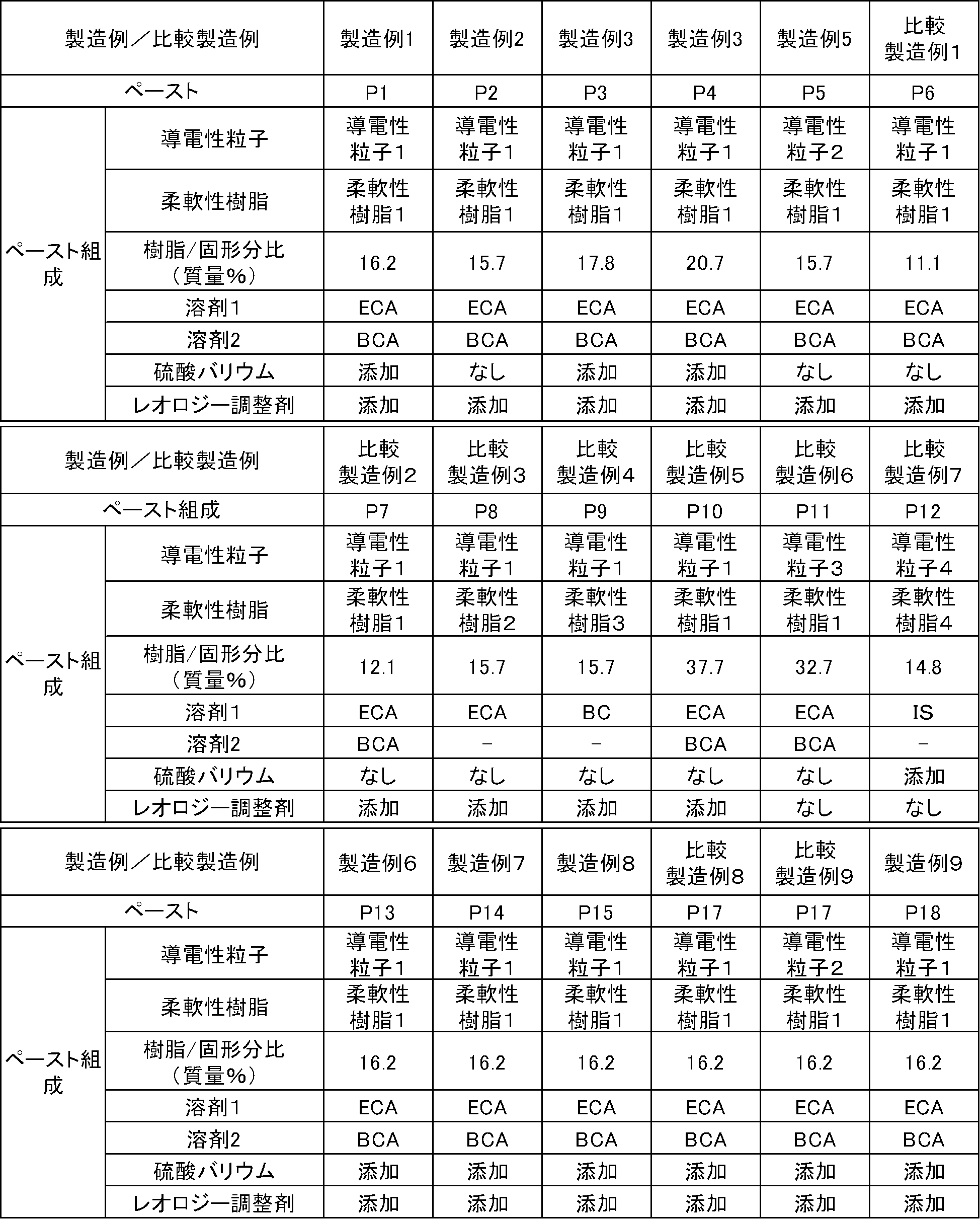
まず、所定の溶剤量の半分量の溶剤に柔軟性樹脂1を溶解し、得られた溶液に導電性粒子1、レオロジー調整剤1、硫酸バリウムを添加して予備混合の後、三本ロールミルにて分散することによりペースト化し、表2に示す伸縮性導体形成用導電ペーストを得た。
以下、材料を変えて同様に操作し、表2に示す伸縮性導体形成用導電ペーストを得た。 <Production example of conductive paste for forming stretchable conductor>
First, the
Hereinafter, the material was changed and the same operation was performed to obtain the conductive paste for forming a stretchable conductor shown in Table 2.
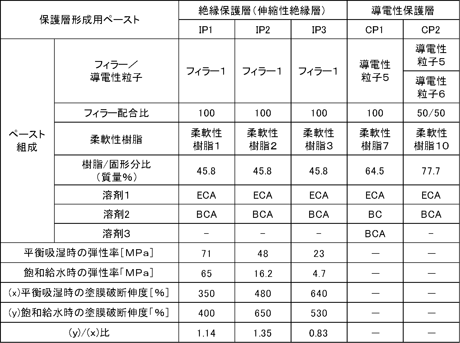
まず、所定の溶剤量の半分量の溶剤に柔軟性樹脂1を溶解し、得られた溶液にフィラー1を添加して予備混合の後、三本ロールミルにて分散することによりペースト化し、表3に示す絶縁保護層形成用の保護層形成用ペースト(IP1)を得た。以下同様に、柔軟性樹脂を代え、同様に表3に示す絶縁保護層形成用の保護層形成用ペースト(IP2)、(IP3)を得た。 <Production example of protective layer forming paste (insulating coating agent) for forming an insulating protective layer>
First, the
まず、所定の溶剤量の半分量の溶剤に柔軟性樹脂1、柔軟性樹脂3を溶解し、得られた溶液に導電性粒子5を添加して予備混合の後、三本ロールミルにて分散することによりペースト化し、表3に示す保護層形成用ペースト(CP1)と(CP2)を得た。 <Production Example of Protective Layer Forming Paste (Carbon Paste) for Conductive Protective Layer Formation>
First, the
導電性粒子1:福田金属箔粉工業株式会社製 微細フレーク状銀粉AGCA 汎用タイプ(平均粒径3μm)
導電性粒子2:メタローテクノロジーズジャパン株式会社 AB5893(平均粒径5.0μm)
導電性粒子3:三菱マテリアル株式会社製 銀コート粉 汎用タイプ(平均粒径1.2μm)
導電性粒子4:DOWAエレクトロニクス株式会社 凝集銀粉G-35(平均粒径6.0μm)
導電性粒子5:ライオン・スペシャリティ・ケミカルズ株式会社製 黒鉛粉末 ケッチェンブラックECP600JD
導電性粒子6:株式会社中越黒鉛工業所製 鱗状黒鉛 グラファイトBF(平均粒径5.0μm)
フィラー1:堺化学工業株式会社 B-34(平均粒径0.3μm)
柔軟性樹脂1:樹脂製造例1にて得られたポリウレタン樹脂A
柔軟性樹脂2:樹脂製造例2にて得られたポリウレタン樹脂B
柔軟性樹脂3:樹脂製造例3にて得られたポリウレタン樹脂C
柔軟性樹脂4:JSR株式会社 極高ニトリルタイプ DN003
柔軟性樹脂7:樹脂製造例7にて得られたポリウレタン樹脂
柔軟性樹脂10:樹脂製造例10にて得られたポリウレタン樹脂
レオロジー調整剤1;共栄社化学 MKコンク
溶剤1:ジエチレングリコールモノエチルエーテルアセテート(ECA)
溶剤2:エチレングリコールモノエチルエーテルアセテート(BCA)
溶剤3: ジエチレングリコールモノブチルエーテル(BC)
溶剤4: イソホロン(IS) The raw materials in Tables 2 and 3 are as follows.
Conductive particles 1: Fukuda Metal Foil Powder Co., Ltd. Fine flake silver powder AGCA General-purpose type (
Conductive particles 2: Metallow Technologies Japan KK AB5893 (average particle size 5.0 μm)
Conductive particles 3: Silver coated powder manufactured by Mitsubishi Materials Corporation General-purpose type (average particle size 1.2 μm)
Conductive particles 4: DOWA Electronics Co., Ltd. Aggregated silver powder G-35 (average particle size 6.0 μm)
Conductive Particle 5: Graphite Powder Ketjen Black ECP600JD manufactured by Lion Specialty Chemicals Co., Ltd.
Conductive particles 6: scaly graphite graphite BF (average particle size 5.0 μm) manufactured by Chuetsu Graphite Industry Co., Ltd.
Filler 1: Sakai Chemical Industry Co., Ltd. B-34 (average particle size 0.3 μm)
Flexible resin 1: Polyurethane resin A obtained in Resin Production Example 1
Flexible resin 2: Polyurethane resin B obtained in Resin Production Example 2
Flexible resin 3: Polyurethane resin C obtained in Resin Production Example 3
Flexible resin 4: JSR Corporation Extremely high nitrile type DN003
Flexible resin 7: Polyurethane resin obtained in Resin Production Example 7 Flexible resin 10: Polyurethane resin obtained in Resin Production Example 10
Solvent 2: Ethylene glycol monoethyl ether acetate (BCA)
Solvent 3: Diethylene glycol monobutyl ether (BC)
Solvent 4: Isophorone (IS)
厚さ100μmの伸縮性の柔軟性樹脂基材上にアプリケーターあるいはスクリーン印刷機にて伸縮性導体形成用導電ペーストを塗布し、100℃で30分間乾燥し、伸縮性導体層(伸縮性導体シート)を作製した。
得られた伸縮性導体層(伸縮性導体シート)の
洗濯耐久性、
(a)40℃24時間浸漬後の塗膜伸度(%)
(b)平衡吸湿状態の塗膜伸度(%)
(a)/(b)比
を表4に示す。 <Production Example and Evaluation of Stretchable Conductor Layer>
A conductive paste for forming a stretchable conductor is applied to a stretchable flexible resin substrate having a thickness of 100 μm with an applicator or a screen printer, and dried at 100° C. for 30 minutes to give a stretchable conductor layer (stretchable conductor sheet). Was produced.
Washing durability of the obtained stretchable conductor layer (stretchable conductor sheet),
(A) Coat elongation (%) after immersion at 40° C. for 24 hours
(B) Coating film elongation (%) in equilibrium moisture absorption state
The (a)/(b) ratio is shown in Table 4.

PET基材の離型フィルム上に、絶縁保護層形成用の保護層形成用ペースト(絶縁コート剤)の製造例にて得られた保護層形成用ペーストIP1を塗布し、表面タックが無くなる直前まで乾燥した。次いで保護層形成用ペースト層の上に基材となる布帛を重ね、ロールラミネータにて軽く圧着させた後、乾燥を継続し、離型フィルムを剥離して、IP1塗膜が片面に形成された布帛を得た。このIP1塗膜を絶縁下地層(第一絶縁層)とする。第一絶縁層は、ほぼ層の半分が布帛(基材)に浸透しており、浸透した層と浸透していない層との層厚の合計は80μmであった。なお、布帛としてはグンセン株式会社製2-wayトリコット生地 KNZ2740(ナイロンヤーン:ウレタンヤーン=63%:37%(混率)、目付け194g/m2)を用いた。
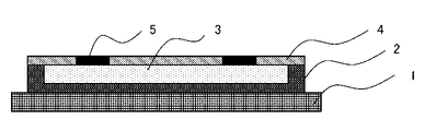
ついでこの第一絶縁層の上に、断面構成が図1となるように、スクリーン印刷機にて導電性ペーストP1を塗布し、100℃で30分間乾燥し、膜厚約25μmの伸縮性導体層を形成した。さらに保護層形成用ペーストIP1をスクリーン印刷して第二絶縁層(伸縮性カバー層、絶縁カバー層)を形成し、布帛上に電極部と配線部を有する伸縮性導電トレースCT1を得た。ここに伸縮性導体層の、第二絶縁層でカバーされていない部分を便宜上電極部、カバーされている部分を便宜上配線部と呼ぶ。
得られた伸縮性トレースの洗濯耐久性を評価した。結果を表5に示す。 <Application Example 1: Direct printing method>
Apply the protective layer forming paste IP1 obtained in the production example of the protective layer forming paste (insulating coating agent) for forming the insulating protective layer onto the release film of the PET base material until just before the surface tack disappears. Dried. Then, a fabric serving as a base material was placed on the protective layer forming paste layer, lightly pressure-bonded with a roll laminator, and then the drying was continued and the release film was peeled off to form an IP1 coating film on one surface. A cloth was obtained. This IP1 coating film is used as an insulating base layer (first insulating layer). About half of the first insulating layer penetrated into the cloth (base material), and the total layer thickness of the permeated layer and the layer not permeated was 80 μm. As the cloth, 2-way tricot fabric KNZ2740 (nylon yarn:urethane yarn=63%:37% (mixing ratio), basis weight 194 g/m2) manufactured by Gunsen Co., Ltd. was used.
Then, on the first insulating layer, a conductive paste P1 was applied by a screen printing machine so as to have a cross-sectional structure shown in FIG. 1 and dried at 100° C. for 30 minutes to give a stretchable conductor layer having a film thickness of about 25 μm. Formed. Further, the protective layer forming paste IP1 was screen-printed to form a second insulating layer (stretchable cover layer, insulating cover layer) to obtain a stretchable conductive trace CT1 having an electrode portion and a wiring portion on the cloth. Here, the part of the stretchable conductor layer which is not covered by the second insulating layer is called an electrode part for convenience, and the covered part is called a wiring part for convenience.
The washing durability of the obtained stretchable trace was evaluated. The results are shown in Table 5.
応用実施例1にて得られた導電トレースの、電極部分に、導電性保護層(電極表面層、伸縮性カーボン層)として、導電性保護層形成用ペーストCP1を印刷、乾燥し、導電性保護層付きの伸縮性導電トレースCT2を得た。得られた伸縮性導電トレースの洗濯耐久性を評価した。結果を表5に示す。 <Application Example 2: Direct printing method>
On the electrode portion of the conductive trace obtained in Application Example 1, a conductive protective layer forming paste CP1 is printed and dried as a conductive protective layer (electrode surface layer, stretchable carbon layer) on the electrode portion to dry the conductive trace. A stretchable conductive trace CT2 with a layer was obtained. The washing durability of the obtained stretchable conductive trace was evaluated. The results are shown in Table 5.
図6の工程図にしたがって、図4の構成となるように操作し、基材となる布帛上に転写法による伸縮性導電性トレースCT3を得た。ここに伸縮性カーボン層としてはCP1、絶縁カバー層としてIP1、伸縮性導体層としてP1、接着層としてIP1を用いた。得られた伸縮性導電トレースの洗濯耐久性を評価した。結果を表5に示す。 <Application Example 3: Print transfer method>
According to the process diagram of FIG. 6, operation was performed so as to have the configuration of FIG. 4, and a stretchable conductive trace CT3 was obtained by a transfer method on the cloth serving as the base material. CP1 was used as the stretchable carbon layer, IP1 was used as the insulating cover layer, P1 was used as the stretchable conductor layer, and IP1 was used as the adhesive layer. The washing durability of the obtained stretchable conductive trace was evaluated. The results are shown in Table 5.
以下同様に表5に示すペーストを用いて、導電性トレースCT4~CT9を得た。結果を表5に示す。 <Application Examples 4 to 6 and Application Comparative Examples 1 to 3>
Similarly, conductive pastes CT4 to CT9 were obtained using the pastes shown in Table 5. The results are shown in Table 5.

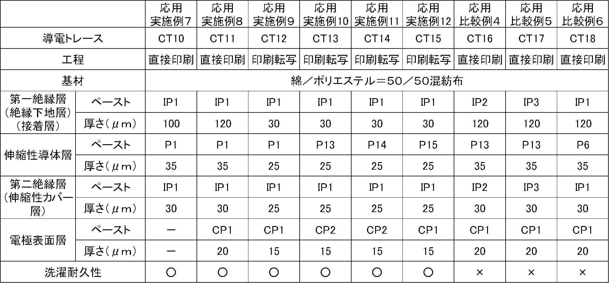
基材用布帛として、綿/ポリエステル50/50混紡の布地を用いたTシャツを使用して、応用実施例にて用いた各プロセスと材料により、図7に示す絶縁下地層、伸縮性導体層、伸縮性カバー層、電極保護層を順次プロセスに従って積層し、心電測定用の導電トレースを配したTシャツを作製した。材料の組み合わせおよびプロセスを表6に示す。
Tシャツには脇下部分に面ファスナーを用いた胴回り調整機構があり、Tシャツ着用後に面ファスナー位置を調整することにより、心電測定用電極が肌に接触するように調整することができる。コネクタ接続部5bには、スナップファスナーをコネクタとして取り付け、着脱式電子ユニットとして、スマートホンへの無線データ伝送機能を有するユニオンツール社製の心拍センサWHS-2を接続し、測定と同時にWHS-2から心電信号をスマートホンに発信し、同心拍センサWHS-2専用のアプリ「myBeat」を組み込んだアップル社製スマートホンで心拍データを受信し、画面表示できるように設定し、さらにRRI(ms(ミリ秒))とHR(bpm(心拍数/分))を測定できるようにした。なおRRIは心電における最も電位差の大きな波であるR波と次のR波との間の時間間隔であり、RRIから(心拍数)=60/(R-R時間(秒))[bpm]を算出することができる。以上のようにして心拍計測機能を持つ生体情報計測用衣類を用いた心電情報計測システムを構成した。 <Application Examples 7 to 12 and Application Comparative Examples 4 to 6>
Using a T-shirt using a cotton/polyester 50/50 mixed fabric as the base fabric, the insulating base layer and the stretchable conductor layer shown in FIG. 7 are formed according to the processes and materials used in the application examples. A stretchable cover layer and an electrode protective layer were sequentially laminated according to the process to prepare a T-shirt on which conductive traces for electrocardiographic measurement were arranged. The material combinations and processes are shown in Table 6.
The T-shirt has a waistline adjustment mechanism using a surface fastener on the armpit. By adjusting the position of the surface fastener after wearing the T-shirt, the electrodes for electrocardiographic measurement can be adjusted so as to contact the skin. A snap fastener as a connector is attached to the
応用実施例7~12、応用比較例4~6にて得られた各生体情報計測用衣類を被験者に着用させ、ラジオ体操第一とラジオ体操第二を連続で実施させ、その間のRRIとHRを計測した。なお試験条件は以下の通りである。
・試験環境 20℃ 50%(動作プロトコル終了時、汗はかいていない)
・電極部はプロトコル開始時に手で押さえ、その後は終了時まで手で押さえない。
・電極部と脇の衣服圧を開始前に計測し
電極部を0.8±0.05kPa、
脇0.7±0.05kPa
となるように調整する。
結果、いずれの生体情報計測用衣類においても旅行にRRIとHRを取得することができた。 <Wearing/exercise test>
The subject wears each of the biological information measuring clothes obtained in Application Examples 7 to 12 and Application Comparative Examples 4 to 6, and the radio exercises 1 and 2 are continuously performed, and RRI and HR between them are performed. Was measured. The test conditions are as follows.
・Test environment: 20℃, 50% (no sweating at the end of operation protocol)
・ Hold the electrode part by hand at the beginning of the protocol, and then do not hold it until the end.
・Measure the clothing pressure on the electrodes and the armpits before starting 0.8±0.05 kPa on the electrodes,
Side 0.7±0.05 kPa
Adjust so that
As a result, it was possible to obtain RRI and HR for travel in any of the biological information measuring clothes.
前記着用・運動試験後に、生体情報計測用衣類の洗濯耐久性試験を行った。結果を表6に示す。 <Washing durability of clothing for measuring biological information>
After the wearing/exercising test, a washing durability test was performed on the clothing for measuring biological information. The results are shown in Table 6.
Sheedom社製のポリウレタンシート DUS605―CD PT5Sを基材に用い、断面構成が図2となるように、スクリーン印刷機にて導電性ペーストP1を塗布し、100℃で30分間乾燥し、膜厚約25μmの伸縮性導体層を形成した。さらに保護層形成用ペーストIP1をスクリーン印刷して第二絶縁層(伸縮性カバー層、絶縁カバー層)を形成し、さらに導電性保護層形成用ペーストCP2を用いて電極保護層を形成し導電トレースCT19を得た。同様に株式会社フォーマンス社製ポリウレタンシート TG88K を用いて同様に操作して導電トレースCT20を得た。CT19、CT20いずれも洗濯耐久性は「○」であった。 <Prototype example using stretchable polymer film as a substrate>
A polyurethane sheet DUS605-CD PT5S manufactured by Sheedom Co., Ltd. is used as a base material, and a conductive paste P1 is applied by a screen printing machine so as to have a cross-sectional structure shown in FIG. A 25 μm stretchable conductor layer was formed. Further, a protective layer forming paste IP1 is screen-printed to form a second insulating layer (stretchable cover layer, insulating cover layer), and an electrically conductive protective layer forming paste CP2 is used to form an electrode protective layer to form a conductive trace. Obtained CT19. Similarly, a conductive sheet CT20 was obtained by the same operation using a polyurethane sheet TG88K manufactured by Forance Co. The washing durability of both CT19 and CT20 was “◯”.
日清紡株式会社製ホットメルト層付きエラストマーシート「モビロン」の非ホットメルト層側に、CT19と同じ構成、操作にて、図7に示す形状の導電トレースCT21付きのエラストマーシートを得た。ついで同エラストマーシートのホットメルト層側を、コンプレッションタイプのTシャツの裏側(着用時に肌と接する側)に合わせて、フッ素樹脂製シートで挟み140土30秒間ホットプレスし、導電トレースCT21付きのコンプレッションタイプのTシャツ:心電測定機能を有する生体情報計測用衣服を得た。得られたTシャツに応用実施例7と同様にスナップファスナーを取り付け、以下同様にユニオンツール社製の心拍センサWHS-2を接続し、同様に着用・運動試験を行った。心電測定機能に不具合は無く、旅行にRRIとHRが測定出来た。着用後に洗濯耐久性試験を行ったが、結果は「○」であった。
同様に、エヌティーダブリュー株式会社 ポリウレタンホットメルトフィルム エスランSHM104-PUR(セパレータ付き)を基材に用い、同じ材料構成、プロセスにて導電とラース22を得て、同様にコンプレッションタイプのTシャツに導電トレースをホットプレスにて貼り付け、心電測定機能を有する生体情報計測用衣服を得た。以下同様に着用・運動試験と洗濯耐久性試験を御個なったあ。結果は良好で会った。
<Prototype example using polyurethane sheet with hot melt>
An elastomer sheet with a conductive trace CT21 having the shape shown in FIG. 7 was obtained on the non-hot melt layer side of the elastomer sheet with hot melt layer “Mobilon” manufactured by Nisshinbo Co., Ltd., by the same configuration and operation as CT19. Then, match the hot melt layer side of the elastomer sheet with the back side of the compression type T-shirt (the side that comes into contact with the skin when worn), sandwich it with a fluororesin sheet, and hot-press for 140 seconds and 30 seconds, and compress with a conductive trace CT21. A type of T-shirt: clothes for measuring biological information having an electrocardiographic measurement function were obtained. A snap fastener was attached to the obtained T-shirt in the same manner as in Application Example 7, and a heart rate sensor WHS-2 manufactured by Union Tool Co. was connected in the same manner, and a wearing/exercise test was conducted in the same manner. There were no problems with the electrocardiogram measurement function, and I was able to measure RRI and HR during travel. A wash durability test was performed after wearing the product, and the result was "○".
Similarly, NTT W Co., Ltd. Polyurethane hot melt film Eslan SHM104-PUR (with separator) was used as the base material, and conductive and Lars 22 were obtained by the same material composition and process, and similarly, a conductive trace was applied to a compression type T-shirt. Was pasted with a hot press to obtain clothes for measuring biological information having an electrocardiographic measurement function. The same is true for the wear/exercise test and the wash durability test. The results were good and met.
2:絶縁下地層
3:伸縮性導体層(伸縮性導体層)
4:伸縮性カバー層(絶縁カバー層、第二絶縁層)
5:伸縮性カーボン層(電極表面層)
5a:皮膚接触電極部
5b:コネクタ接続部
6:接着層(絶縁下地層、第一絶縁層)
10:仮支持体(離型支持体)
20:心電測定用の伸縮性電極と伸縮性配線部
1: Base material (fabric)
2: Insulating base layer 3: Stretchable conductor layer (stretchable conductor layer)
4: Elastic cover layer (insulating cover layer, second insulating layer)
5: Stretchable carbon layer (electrode surface layer)
5a: Skin
10: Temporary support (release support)
20: Elastic electrode and elastic wiring part for electrocardiographic measurement
Claims (23)
- 導電性粒子と柔軟性樹脂とを少なくとも含有する伸縮性導体形成用導電ペーストにおいて、該柔軟性樹脂の飽和含水率が5質量%以下であり、該柔軟性樹脂の配合量が、伸縮性導体形成用導電ペーストの全固形分の合計に対して13質量%~35質量%であることを特徴とする伸縮性導体形成用導電ペースト。 In a conductive paste for forming a stretchable conductor containing at least conductive particles and a flexible resin, the flexible resin has a saturated water content of 5% by mass or less, and the blending amount of the flexible resin is such that the stretchable conductor is formed. A conductive paste for forming a stretchable conductor, wherein the conductive paste is 13 mass% to 35 mass% with respect to the total solid content of the conductive paste.
- 前記柔軟性樹脂が非架橋のポリウレタン樹脂であることを特徴とする請求項1に記載の伸縮性導体形成用導電ペースト。 The conductive paste for forming a stretchable conductor according to claim 1, wherein the flexible resin is a non-crosslinked polyurethane resin.
- 前記柔軟性樹脂のガラス転移温度が、-10℃以上、+10℃以下であることを特徴とする請求項1または2に記載の伸縮性導体形成用導電ペースト。 The conductive paste for forming a stretchable conductor according to claim 1 or 2, wherein the glass transition temperature of the flexible resin is -10°C or higher and +10°C or lower.
- 請求項1~3のいずれかに記載の伸縮性導体形成用導電ペーストを基材に印刷ないし塗布した後に乾燥して得られる伸縮性導体層であって、該伸縮性導体層の40℃における飽和含水状態に於ける破断伸度ε’が500%以上であることを特徴とする伸縮性導体層。 A stretchable conductor layer obtained by printing or coating the stretchable conductor-forming conductive paste according to any one of claims 1 to 3 on a substrate and then drying the paste, wherein the stretchable conductor layer is saturated at 40°C. A stretchable conductor layer having a breaking elongation ε'of 500% or more in a water-containing state.
- 請求項4に記載の伸縮性導体層において、平衡吸湿状態に於ける破断伸度εと、40℃における飽和含水状態に於ける破断伸度ε’が、
ε’/ε>0.5
なる関係を示すことを特徴とする伸縮性導体層。 In the stretchable conductor layer according to claim 4, the breaking elongation ε in the equilibrium moisture absorption state and the breaking elongation ε′ in the saturated water content state at 40° C.
ε'/ε>0.5
A stretchable conductor layer having the following relationship. - 請求項1~3のいずれかに記載の伸縮性導体形成用導電ペーストを、伸縮性の基材に印刷ないし塗布した後に、少なくとも70℃以上120℃以下の温度にて乾燥する工程を経ることにより、飽和含水率が5質量%以下である伸縮性導体層を得ることを特徴とする伸縮性導体層の製造方法。 By printing or applying the conductive paste for forming a stretchable conductor according to any one of claims 1 to 3 on a stretchable substrate, and then performing a step of drying at a temperature of at least 70°C to 120°C. A method for producing a stretchable conductor layer, comprising obtaining a stretchable conductor layer having a saturated water content of 5% by mass or less.
- 請求項1~3のいずれかに記載の伸縮性導体形成用導電ペーストを、非伸縮性の離型基材に印刷ないし塗布した後に、少なくとも70℃以上120℃以下の温度にて乾燥する工程を経ることにより、飽和含水率が5質量%以下である伸縮性導体層を得ることを特徴とする伸縮性導体層の製造方法。 A step of printing or applying the stretchable conductor-forming conductive paste according to any one of claims 1 to 3 onto a non-stretchable release substrate, and then drying at a temperature of at least 70°C to 120°C. A process for producing a stretchable conductor layer, which comprises obtaining a stretchable conductor layer having a saturated water content of 5% by mass or less.
- 繊維構造体からなる基材、生体表面に直接接触する伸縮性電極、伸縮性電気配線、伸縮性絶縁層を少なくとも有する伸縮性電気配線構成体において、前記伸縮性絶縁層が、飽和含水率が5質量%以下であり、かつ、飽和含水時における弾性率が10MPa以上1000MPa以下である柔軟性樹脂組成物からなることを特徴とする伸縮性電気配線構成体。 In a stretchable electrical wiring structure having at least a substrate made of a fibrous structure, a stretchable electrode in direct contact with the surface of a living body, a stretchable electrical wiring, and a stretchable insulating layer, the stretchable insulating layer has a saturated water content of 5 A stretchable electrical wiring structure comprising a flexible resin composition having a mass% of less than or equal to and an elastic modulus of 10 MPa or more and 1000 MPa or less when saturated with water.
- 前記伸縮性絶縁層が、伸縮性電気配線構成体の生体表面に面する側に形成されていることを特徴とする請求項8に記載の伸縮性電気配線構成体。 The stretchable electrical wiring structure according to claim 8, wherein the stretchable insulating layer is formed on the side of the stretchable electrical wiring configuration facing the surface of the living body.
- 前記伸縮性絶縁層が、伸縮性電極およびまたは伸縮性電気配線と繊維構造体からなる基材との間に形成されていることを特徴とする請求項8または9に記載の伸縮性電気配線構成体。 10. The stretchable electrical wiring structure according to claim 8 or 9, wherein the stretchable insulating layer is formed between the stretchable electrode and/or the stretchable electrical wiring and a base material made of a fibrous structure. body.
- 前記伸縮性絶縁層が、繊維構造体からなる基材の、伸縮性電極およびまたは伸縮性電気配線が形成されている面とは反対側の面に形成されていることを特徴とする請求項8~10のいずれかに記載の伸縮性電気配線構成体。 9. The stretchable insulating layer is formed on a surface of a base material made of a fibrous structure opposite to a surface on which the stretchable electrode and/or the stretchable electric wiring is formed. 11. The stretchable electrical wiring structure according to any one of 10 to 10.
- 前記伸縮性電極および、または伸縮性電気配線を構成する伸縮性導電層の飽和含水率が5質量%以下であることを特徴とする請求項8~11のいずれかに記載の伸縮性電気配線構成体。 The stretchable electrical wiring structure according to any one of claims 8 to 11, wherein the stretchable conductive layer constituting the stretchable electrode and/or the stretchable electrical wiring has a saturated water content of 5% by mass or less. body.
- 前記伸縮性導電層が、少なくとも導電性粒子と柔軟性樹脂を含み、該柔軟性樹脂の飽和含水率が5質量%以下であり、該柔軟性樹脂の伸縮性導体層に対する配合量が13質量%~35質量%であることを特徴とする請求項8~12のいずれかに記載の伸縮性電気配線構成体。 The stretchable conductive layer contains at least conductive particles and a flexible resin, the flexible resin has a saturated water content of 5 mass% or less, and the blending amount of the flexible resin with respect to the stretchable conductive layer is 13 mass%. Stretchable electrical wiring structure according to any one of claims 8 to 12, characterized in that it is ˜35% by mass.
- 前記柔軟性樹脂のガラス転移温度が、-10℃以上、+10℃以下であることを特徴とする請求項8~13のいずれかに記載の伸縮性電気配線構成体。 The stretchable electrical wiring structure according to any one of claims 8 to 13, wherein the glass transition temperature of the flexible resin is -10°C or higher and +10°C or lower.
- 前記伸縮性絶縁層の40℃における飽和含水状態に於ける破断伸度ε’が500%以上であることを特徴とする請求項8~14のいずれかに記載の伸縮性電気配線構成体。 The stretchable electrical wiring structure according to any one of claims 8 to 14, wherein the stretchable insulating layer has a breaking elongation ε'of 500% or more in a saturated water content state at 40°C.
- 前記伸縮性絶縁層の平衡吸湿状態に於ける破断伸度εと、40℃における飽和含水状態に於ける破断伸度ε’が、
ε’/ε>0.5
なる関係を示すことを特徴とする請求項8~15のいずれかに記載の伸縮性電気配線構成体。 The elongation at break ε in the equilibrium moisture absorption state of the elastic insulating layer and the elongation at break ε′ in the saturated water content at 40° C.
ε'/ε>0.5
The stretchable electrical wiring structure according to any one of claims 8 to 15, characterized in that - 前記柔軟性樹脂が非架橋のポリウレタン樹脂であることを特徴とする請求項8~16のいずれかに記載の伸縮性電気配線構成体。 The stretchable electrical wiring structure according to any one of claims 8 to 16, wherein the flexible resin is a non-crosslinked polyurethane resin.
- 前記柔軟性樹脂が、樹脂骨格中に芳香族を13質量%以上含有するポリエステル系あるいはポリカーボネート系ポリウレタン樹脂であることを特徴とする請求項8~17のいずれかに記載の伸縮性電気配線構成体。 The stretchable electric wiring structure according to any one of claims 8 to 17, wherein the flexible resin is a polyester-based or polycarbonate-based polyurethane resin containing 13% by mass or more of an aromatic in a resin skeleton. ..
- 生体表面に直接接する伸縮性電極を有する生体情報計測装置において、該伸縮性電極を構成する伸縮性導体層が請求項4または5記載の伸縮性導体層であることを特徴とする生体情報計測装置。 A biological information measuring device having a stretchable electrode in direct contact with the surface of a living body, wherein the stretchable conductive layer constituting the stretchable electrode is the stretchable conductive layer according to claim 4 or 5. ..
- 前記伸縮性電極と同じ伸縮性導体層にて伸縮性電気配線が形成されていることを特徴とする請求項19に記載の生体情報計測装置。 The biological information measuring device according to claim 19, wherein the stretchable electric wiring is formed of the same stretchable conductor layer as the stretchable electrode.
- 前記伸縮性電極の表面に炭素系フィラーを導電成分として有する導電性保護膜を有することを特徴とする請求項19に記載の生体情報計測装置。 The biological information measuring device according to claim 19, wherein a conductive protective film having a carbon-based filler as a conductive component is provided on the surface of the stretchable electrode.
- 前記伸縮性電極およびまたは伸縮性電気配線の、生体表面との接触面側とは反対の面に、飽和含水率が5質量%以下であり、かつ、含水率が0~5質量%の範囲において弾性率が10MPa以上1000MPa以下である柔軟性樹脂をからなる層を有することを特徴とする請求項19~21のいずれかに記載の生体情報計測装置。 On the surface of the stretchable electrode and/or the stretchable electric wire opposite to the contact surface side with the living body surface, the saturated water content is 5% by mass or less, and the water content is in the range of 0 to 5% by mass. The biological information measuring device according to any one of claims 19 to 21, further comprising a layer made of a flexible resin having an elastic modulus of 10 MPa or more and 1000 MPa or less.
- 前記伸縮性電気配線の生体表面との接触面側に、飽和含水率が5質量%以下であり、かつ、含水率が0~5質量%の範囲において弾性率が10MPa以上1000MPa以下である柔軟性樹脂をからなる絶縁層を有することを特徴とする請求項20~22のいずれかに記載の生体情報計測装置。
Flexibility that the saturated water content is 5% by mass or less and the elastic modulus is 10 MPa or more and 1000 MPa or less in the range of 0 to 5% by mass on the contact surface side of the elastic electric wiring with the biological surface. 23. The biological information measuring device according to claim 20, further comprising an insulating layer made of resin.
Priority Applications (5)
| Application Number | Priority Date | Filing Date | Title |
|---|---|---|---|
| CN201980085800.9A CN113226729A (en) | 2018-12-27 | 2019-12-27 | Conductive paste for forming stretchable conductor, stretchable conductor layer, method for producing stretchable conductor layer, stretchable electrical wiring structure, and biological information measurement device |
| KR1020217023192A KR20210108988A (en) | 2018-12-27 | 2019-12-27 | Conductive paste for forming a stretchable conductor, a stretchable conductor layer, a method for manufacturing a stretchable conductor layer, a stretchable electrical wiring structure, and an apparatus for measuring biometric information |
| JP2020562538A JPWO2020138477A1 (en) | 2018-12-27 | 2019-12-27 | |
| EP19904083.3A EP3904068A4 (en) | 2018-12-27 | 2019-12-27 | Conductive paste for forming stretchable conductor, stretchable conductor layer, method for producing stretchable conductor layer, stretchable electrical wiring structure, and biometric information measuring device |
| US17/349,265 US20210307666A1 (en) | 2018-12-27 | 2021-06-16 | Conductive paste for forming stretchable conductor, stretchable conductor layer, method for producing stretchable conductor layer, stretchable electrical wiring structure, and biological information measurement device |
Applications Claiming Priority (6)
| Application Number | Priority Date | Filing Date | Title |
|---|---|---|---|
| JP2018-245696 | 2018-12-27 | ||
| JP2018-245694 | 2018-12-27 | ||
| JP2018245694 | 2018-12-27 | ||
| JP2018245695 | 2018-12-27 | ||
| JP2018-245695 | 2018-12-27 | ||
| JP2018245696 | 2018-12-27 |
Related Child Applications (1)
| Application Number | Title | Priority Date | Filing Date |
|---|---|---|---|
| US17/349,265 Continuation-In-Part US20210307666A1 (en) | 2018-12-27 | 2021-06-16 | Conductive paste for forming stretchable conductor, stretchable conductor layer, method for producing stretchable conductor layer, stretchable electrical wiring structure, and biological information measurement device |
Publications (1)
| Publication Number | Publication Date |
|---|---|
| WO2020138477A2 true WO2020138477A2 (en) | 2020-07-02 |
Family
ID=71130151
Family Applications (1)
| Application Number | Title | Priority Date | Filing Date |
|---|---|---|---|
| PCT/JP2019/051558 WO2020138477A2 (en) | 2018-12-27 | 2019-12-27 | Conductive paste for forming stretchable conductor, stretchable conductor layer, method for producing stretchable conductor layer, stretchable electrical wiring structure, and biometric information measuring device |
Country Status (7)
| Country | Link |
|---|---|
| US (1) | US20210307666A1 (en) |
| EP (1) | EP3904068A4 (en) |
| JP (1) | JPWO2020138477A1 (en) |
| KR (1) | KR20210108988A (en) |
| CN (1) | CN113226729A (en) |
| TW (1) | TWI816005B (en) |
| WO (1) | WO2020138477A2 (en) |
Cited By (4)
| Publication number | Priority date | Publication date | Assignee | Title |
|---|---|---|---|---|
| TWI759828B (en) * | 2020-08-20 | 2022-04-01 | 友達光電股份有限公司 | Stretchable electronic device |
| JP2022083344A (en) * | 2020-11-24 | 2022-06-03 | 東和株式会社 | Electrode pad for wearable device |
| JP7302761B1 (en) | 2022-03-24 | 2023-07-04 | 東レ株式会社 | Bioelectrode and manufacturing method thereof |
| WO2023181631A1 (en) * | 2022-03-24 | 2023-09-28 | 東レ株式会社 | Bioelectrode and method for manufacturing same |
Families Citing this family (1)
| Publication number | Priority date | Publication date | Assignee | Title |
|---|---|---|---|---|
| TWI815553B (en) * | 2022-07-14 | 2023-09-11 | 友達光電股份有限公司 | Circuit structure |
Citations (4)
| Publication number | Priority date | Publication date | Assignee | Title |
|---|---|---|---|---|
| JP5363592B2 (en) | 2010-05-19 | 2013-12-11 | 東海ゴム工業株式会社 | Conductive film, transducer using the same, and flexible wiring board |
| JP5486268B2 (en) | 2008-11-18 | 2014-05-07 | 東海ゴム工業株式会社 | Conductive film, transducer including the same, and flexible wiring board |
| WO2015119217A1 (en) | 2014-02-05 | 2015-08-13 | 独立行政法人科学技術振興機構 | Stretchable conductor, method for manufacturing same, and paste for forming stretchable conductor |
| WO2017154726A1 (en) | 2016-03-08 | 2017-09-14 | 東洋紡株式会社 | Stretchable conductor sheet, stretchable conductor sheet having adhesiveness, and method for forming wiring line formed of stretchable conductor on fabric |
Family Cites Families (7)
| Publication number | Priority date | Publication date | Assignee | Title |
|---|---|---|---|---|
| KR102430695B1 (en) * | 2015-01-14 | 2022-08-08 | 도요보 가부시키가이샤 | Flexible electrode and wiring sheet, interface for biometric information measurement |
| JP6724348B2 (en) * | 2015-11-27 | 2020-07-15 | 東洋紡株式会社 | Electrocardiogram measurement method and electrocardiogram measurement clothing |
| JP6660542B2 (en) * | 2015-11-30 | 2020-03-11 | タツタ電線株式会社 | Stretchable conductive film for textile |
| JP6859760B2 (en) * | 2016-03-08 | 2021-04-14 | 東洋紡株式会社 | Elastic conductor forming paste, elastic conductor sheet and probe for biometric information measurement |
| WO2017154978A1 (en) * | 2016-03-09 | 2017-09-14 | 東洋紡株式会社 | Elastic conductor sheet and paste for forming elastic conductor sheet |
| CN108778011B (en) * | 2016-03-16 | 2021-02-12 | 东洋纺株式会社 | Wearable intelligent device |
| JP7167909B2 (en) * | 2017-03-02 | 2022-11-09 | 東洋紡株式会社 | Conductive paste, stretchable wiring using the same, clothing-type electronic device having stretchable wiring |
-
2019
- 2019-12-27 WO PCT/JP2019/051558 patent/WO2020138477A2/en active Search and Examination
- 2019-12-27 CN CN201980085800.9A patent/CN113226729A/en active Pending
- 2019-12-27 TW TW108148104A patent/TWI816005B/en active
- 2019-12-27 KR KR1020217023192A patent/KR20210108988A/en not_active Application Discontinuation
- 2019-12-27 JP JP2020562538A patent/JPWO2020138477A1/ja active Pending
- 2019-12-27 EP EP19904083.3A patent/EP3904068A4/en not_active Withdrawn
-
2021
- 2021-06-16 US US17/349,265 patent/US20210307666A1/en active Pending
Patent Citations (4)
| Publication number | Priority date | Publication date | Assignee | Title |
|---|---|---|---|---|
| JP5486268B2 (en) | 2008-11-18 | 2014-05-07 | 東海ゴム工業株式会社 | Conductive film, transducer including the same, and flexible wiring board |
| JP5363592B2 (en) | 2010-05-19 | 2013-12-11 | 東海ゴム工業株式会社 | Conductive film, transducer using the same, and flexible wiring board |
| WO2015119217A1 (en) | 2014-02-05 | 2015-08-13 | 独立行政法人科学技術振興機構 | Stretchable conductor, method for manufacturing same, and paste for forming stretchable conductor |
| WO2017154726A1 (en) | 2016-03-08 | 2017-09-14 | 東洋紡株式会社 | Stretchable conductor sheet, stretchable conductor sheet having adhesiveness, and method for forming wiring line formed of stretchable conductor on fabric |
Non-Patent Citations (1)
| Title |
|---|
| See also references of EP3904068A4 |
Cited By (4)
| Publication number | Priority date | Publication date | Assignee | Title |
|---|---|---|---|---|
| TWI759828B (en) * | 2020-08-20 | 2022-04-01 | 友達光電股份有限公司 | Stretchable electronic device |
| JP2022083344A (en) * | 2020-11-24 | 2022-06-03 | 東和株式会社 | Electrode pad for wearable device |
| JP7302761B1 (en) | 2022-03-24 | 2023-07-04 | 東レ株式会社 | Bioelectrode and manufacturing method thereof |
| WO2023181631A1 (en) * | 2022-03-24 | 2023-09-28 | 東レ株式会社 | Bioelectrode and method for manufacturing same |
Also Published As
| Publication number | Publication date |
|---|---|
| EP3904068A4 (en) | 2022-09-21 |
| CN113226729A (en) | 2021-08-06 |
| EP3904068A2 (en) | 2021-11-03 |
| KR20210108988A (en) | 2021-09-03 |
| TWI816005B (en) | 2023-09-21 |
| US20210307666A1 (en) | 2021-10-07 |
| TW202031809A (en) | 2020-09-01 |
| JPWO2020138477A1 (en) | 2020-07-02 |
Similar Documents
| Publication | Publication Date | Title |
|---|---|---|
| JP7078149B2 (en) | Elastic conductor sheet | |
| WO2020138477A2 (en) | Conductive paste for forming stretchable conductor, stretchable conductor layer, method for producing stretchable conductor layer, stretchable electrical wiring structure, and biometric information measuring device | |
| TWI697915B (en) | Stretchable conductor sheet, stretchable conductor sheet with adhesiveness, and method for forming wiring on stretch fabric | |
| TWI712370B (en) | Clothing-type electronic equipment and manufacturing method of clothing-type electronic equipment | |
| WO2016114298A1 (en) | Stretchable electrode and wiring sheet, and biological information measurement interface | |
| TWI758423B (en) | Conductive paste, stretchable wiring using the same, and clothing-type electronic device having stretchable wiring | |
| WO2018074402A1 (en) | Elastic conductive sheet, elastic wiring, elastic wiring-equipped fabric, and method for restoring conductivity | |
| JP6874382B2 (en) | Body measurement equipment and body size measurement method, clothing selection system, custom-made clothing design system | |
| WO2018056062A1 (en) | Stretchable capacitor, deformation sensor, displacement sensor, method for sensing respiration state, and sensing wear | |
| US11469010B2 (en) | Conductive paste, stretchable conductor and electronic component using same, and clothes-type electronic device | |
| JP6996214B2 (en) | Wearable biometric information measuring device and biometric information measuring method | |
| TWI772551B (en) | Clothing for biometric information measurement, stretchable laminated sheet, and manufacturing method of stretchable laminated sheet | |
| JP2021088802A (en) | Anthropometric instrument and body size measuring method, clothes selection system and custom-made clothes design system | |
| JP2021088801A (en) | Anthropometric instrument and body size measuring method, clothes selection system and custom-made clothes design system | |
| CN115551712A (en) | Conductive laminate sheet for attaching clothing to clothes and method for producing same |
Legal Events
| Date | Code | Title | Description |
|---|---|---|---|
| 121 | Ep: the epo has been informed by wipo that ep was designated in this application |
Ref document number: 19904083 Country of ref document: EP Kind code of ref document: A2 |
|
| DPE1 | Request for preliminary examination filed after expiration of 19th month from priority date (pct application filed from 20040101) | ||
| ENP | Entry into the national phase |
Ref document number: 2020562538 Country of ref document: JP Kind code of ref document: A |
|
| NENP | Non-entry into the national phase |
Ref country code: DE |
|
| ENP | Entry into the national phase |
Ref document number: 20217023192 Country of ref document: KR Kind code of ref document: A |
|
| ENP | Entry into the national phase |
Ref document number: 2019904083 Country of ref document: EP Effective date: 20210727 |