WO2020137983A1 - 電流検知素子、電流検知素子複合体および保護回路 - Google Patents
電流検知素子、電流検知素子複合体および保護回路 Download PDFInfo
- Publication number
- WO2020137983A1 WO2020137983A1 PCT/JP2019/050382 JP2019050382W WO2020137983A1 WO 2020137983 A1 WO2020137983 A1 WO 2020137983A1 JP 2019050382 W JP2019050382 W JP 2019050382W WO 2020137983 A1 WO2020137983 A1 WO 2020137983A1
- Authority
- WO
- WIPO (PCT)
- Prior art keywords
- conductor
- melting point
- fuse element
- point metal
- fuse
- Prior art date
- Legal status (The legal status is an assumption and is not a legal conclusion. Google has not performed a legal analysis and makes no representation as to the accuracy of the status listed.)
- Ceased
Links
Images


Classifications
-
- G—PHYSICS
- G01—MEASURING; TESTING
- G01R—MEASURING ELECTRIC VARIABLES; MEASURING MAGNETIC VARIABLES
- G01R15/00—Details of measuring arrangements of the types provided for in groups G01R17/00 - G01R29/00, G01R33/00 - G01R33/26 or G01R35/00
-
- H—ELECTRICITY
- H01—ELECTRIC ELEMENTS
- H01H—ELECTRIC SWITCHES; RELAYS; SELECTORS; EMERGENCY PROTECTIVE DEVICES
- H01H37/00—Thermally-actuated switches
- H01H37/74—Switches in which only the opening movement or only the closing movement of a contact is effected by heating or cooling
- H01H37/76—Contact member actuated by melting of fusible material, actuated due to burning of combustible material or due to explosion of explosive material
-
- H—ELECTRICITY
- H02—GENERATION; CONVERSION OR DISTRIBUTION OF ELECTRIC POWER
- H02H—EMERGENCY PROTECTIVE CIRCUIT ARRANGEMENTS
- H02H3/00—Emergency protective circuit arrangements for automatic disconnection directly responsive to an undesired change from normal electric working condition with or without subsequent reconnection ; integrated protection
- H02H3/08—Emergency protective circuit arrangements for automatic disconnection directly responsive to an undesired change from normal electric working condition with or without subsequent reconnection ; integrated protection responsive to excess current
- H02H3/087—Emergency protective circuit arrangements for automatic disconnection directly responsive to an undesired change from normal electric working condition with or without subsequent reconnection ; integrated protection responsive to excess current for DC applications
-
- H—ELECTRICITY
- H02—GENERATION; CONVERSION OR DISTRIBUTION OF ELECTRIC POWER
- H02H—EMERGENCY PROTECTIVE CIRCUIT ARRANGEMENTS
- H02H7/00—Emergency protective circuit arrangements specially adapted for specific types of electric machines or apparatus or for sectionalised protection of cable or line systems, and effecting automatic switching in the event of an undesired change from normal working conditions
- H02H7/18—Emergency protective circuit arrangements specially adapted for specific types of electric machines or apparatus or for sectionalised protection of cable or line systems, and effecting automatic switching in the event of an undesired change from normal working conditions for batteries; for accumulators
-
- H—ELECTRICITY
- H02—GENERATION; CONVERSION OR DISTRIBUTION OF ELECTRIC POWER
- H02J—ELECTRIC POWER NETWORKS; CIRCUIT ARRANGEMENTS OR SYSTEMS FOR SUPPLYING OR DISTRIBUTING ELECTRIC POWER; SYSTEMS FOR STORING ELECTRIC ENERGY
- H02J7/00—Circuit arrangements for charging or discharging batteries or for supplying loads from batteries
Definitions
- the present invention relates to a current detection element, a current detection element composite and a protection circuit, for example, a current detection element and a current detection element composite connected between a secondary battery and a charging device in a charging/discharging circuit of a secondary battery. And a protection circuit.
- a current detection element for example, a current detection element and a current detection element composite connected between a secondary battery and a charging device in a charging/discharging circuit of a secondary battery.
- a protection circuit for example, a current detection element and a current detection element composite connected between a secondary battery and a charging device in a charging/discharging circuit of a secondary battery.
- a protection circuit for example, a current detection element and a current detection element composite connected between a secondary battery and a charging device in a charging/discharging circuit of a secondary battery.
- a protection circuit for example, a current detection element and a current detection element composite connected between a secondary battery and a charging device in a charging/discharging circuit
- the protection circuit has been implemented in various devices equipped with a secondary battery, such as mobile devices such as mobile phones and portable computers, and rechargeable electric devices.
- a secondary battery such as mobile devices such as mobile phones and portable computers, and rechargeable electric devices.
- a battery pack that is detachably mounted on a power tool body configured as a driver drill and supplies power to the power tool body (Patent Document 1).
- This battery pack is equipped with a battery, an IC such as AFE (analog front end) for battery status detection, and a control circuit.
- the IC such as the AFE detects the cell voltages of a plurality of battery cells that compose the battery in accordance with a command from the control circuit, and charges the battery through a current detection resistor provided in the negative power supply line of the battery. It is configured to detect the current and the discharge current from the battery. Further, a discharge current detection circuit that detects a discharge current is connected to the current detection resistor, and the discharge current detection circuit is configured to determine whether or not the discharge current has reached a predetermined overload determination threshold value. The load determination circuit is connected. Then, the detection result by the discharge current detection circuit and the determination result by the overload determination circuit are input to the control circuit.
- AFE analog front end
- this battery pack is equipped with a shutoff switch that shuts off the positive power line.
- the cutoff switch is composed of three protection elements each having a fuse portion provided on the positive electrode side power supply line and a heater portion (heating resistor) that generates heat when energized to melt the fuse portion. Further, the cut-off switch may be installed in the negative power supply line.
- the current detection resistor is called a shunt resistor, and is usually composed of a main conductor formed of manganin (for example, CuMnNi alloy) or NiCr alloy having a small temperature coefficient of resistance.
- a shunt resistor is used in a charge/discharge circuit, when an abnormal current is detected, it is necessary to stop the energization of the battery by melting the fuse part of the protection element connected in series with the shunt resistor. That is, it is necessary to mount both the current detection resistor and the protection element in the protection circuit, which complicates the device configuration and makes it difficult to further reduce the device size.
- An object of the present invention is to provide a current detection element, a current detection element complex, and a protection circuit that can realize simplification of the configuration of the protection circuit, further downsizing of the device, and cost reduction.
- the present invention provides the following means.
- the conductor includes a first fuse element and a second fuse element connected in series, The current sensing element composite body according to [6], wherein the heating element is connected between the first fuse element and the second fuse element.
- a first electrode portion connected to a side of the first fuse element opposite to the second fuse element, A second electrode portion connected to the opposite side of the second fuse element from the first fuse element; A third electrode portion connected between the first fuse element and the second fuse element and connected to the heating element;
- the current sensing element composite according to the above [10], further comprising: [12] A conductor having a low melting point metal layer formed of a low melting point metal, a heating element connected to the conductor and capable of fusing the conductor by heating, and a temperature measuring element for measuring the temperature of the conductor.
- a current sensing element having A current measuring element that corrects the resistance temperature coefficient of the conductor based on the temperature of the conductor obtained from the output of the temperature measuring element, and measures the current flowing through the conductor using the corrected resistance temperature coefficient.
- a first protection device that detects an abnormality in a current-carrying path connected to the conductor of the current-sensing element and electrically heats the heating element of the current-sensing element; Protection circuit with. [13] The first protection device detects a voltage of a battery connected to an energization path of the current detection element, and determines whether or not an abnormality has occurred in the battery based on the voltage, [12] ] The protection circuit described in.
- a second protection device for controlling charging/discharging of a battery connected to the protection circuit is further provided, The protection circuit according to the above [13], wherein the second protection device detects an abnormality in an energization path of the current detection element based on a measured value of a current flowing through the conductor and stops the energization path.
- the temperature measuring element is a temperature variable resistance element or a thermocouple connected to a path different from the path of the conductor and the heating element.
- the current detection element is A first electrode portion connected to the opposite side of the first fuse element from the second fuse element; A second electrode portion connected to the opposite side of the second fuse element from the first fuse element; A third electrode portion connected between the first fuse element and the second fuse element and connected to the heating element; Further has The protection circuit according to the above [17], wherein at least one of the first fuse element and the second fuse element is blown when an abnormality occurs in the energization path connected to the conductor of the current detection element. ..
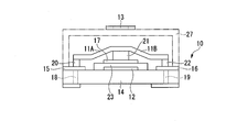
- FIG. 1A is a plan view schematically showing the configuration of a current detection element according to the first embodiment of the present invention.
- FIG. 1B is a side view schematically showing the configuration of the current detection element according to the first embodiment of the present invention.
- FIG. 2 is a circuit diagram schematically showing the configuration of the protection circuit according to the second embodiment of the present invention.
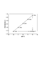
- FIG. 3 is a graph illustrating a method of correcting the temperature coefficient of resistance of the conductor in the current measuring element of FIG.
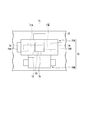
- FIG. 4 is a plan view schematically showing the configuration of the current sensing element composite body according to the third embodiment of the present invention.
- FIG. 1A is a plan view schematically showing the configuration of the current detection element according to the first embodiment of the present invention
- FIG. 1B is a side view.
- a current detection element mounted on a mobile device such as a mobile phone will be described as an example.
- the current detection element 10 includes a conductor 11 having a low melting point metal layer, a heating element 12 connected to the conductor 11 and capable of fusing the conductor 11 by heating, and a temperature of the conductor 11. And a temperature measuring element 13 for measuring. Further, in the present embodiment, the current detection element 10 includes the substrate 14, the first electrode portion 15 connected to one end of the conductor 11, the second electrode portion 16 connected to the other end of the conductor 11, A third electrode portion 17 connected to the central portion of the conductor 11 and connected to the heating element 12, a first conduction portion 18 for electrically connecting the first electrode portion 15 and an external circuit, a second electrode portion 16 and the outside. And a second conducting portion 19 for conducting the circuit.
- the conductor 11 has both a function as a shunt resistance element for current detection and a function as a fuse element that can be blown by heating when overvoltage or overcurrent is detected.
- the conductor 11 is composed of, for example, a first fuse element 11A and a second fuse element 11B that are connected in series on a substrate 14.
- the heating element 12 is connected between the first fuse element 11A and the second fuse element 11B (see FIG. 2).
- the first electrode portion 15 is connected to the opposite side of the first fuse element 11A from the second fuse element 11B
- the second electrode portion 16 is connected to the first fuse element 11A of the second fuse element 11B.
- the third electrode portion 17 is connected between the first fuse element 11A and the second fuse element 11B and is also connected in series with the heating element 12.
- the first fuse element 11A and the second fuse element 11B are integrally formed in the present embodiment, and the first electrode portion 15 is formed via three conductive supports 20, 21, 22 made of, for example, solder or the like. , And is supported by the second electrode portion 16 and the third electrode portion 17.
- the first fuse element 11A and the second fuse element 11B are integrally formed, but the present invention is not limited to this, and they may be formed as separate members.
- the first fuse element 11A and the second fuse element 11B are, for example, flaky.
- the first fuse element 11A and the second fuse element 11B may be rod-shaped.
- the length of the first fuse element 11A is the same as the length of the second fuse element 11B, but the length is not limited to this and may be different from that of the second fuse element 11B.
- the length of the first fuse element 11A may be longer than the length of the second fuse element 11B.
- the conductor 11 is preferably a laminated body including the low melting point metal layer and a high melting point metal layer made of a high melting point metal having a higher melting point than the low melting point metal.
- the first fuse element 11A and the second fuse element 11B are also a laminated body including a low melting point metal layer and a high melting point metal layer formed of a high melting point metal having a higher melting point than the low melting point metal.
- the conductor 11 formed of the laminated body has a coating structure including a low melting point metal layer as an inner layer and a high melting point metal layer as an outer layer that covers the low melting point metal layer as the inner layer. More preferable.
- the low melting point metal layer As the material forming the low melting point metal layer, various low melting point metals conventionally used as fuse materials can be used. Examples of the low melting point metal include SnSb alloy, BiSnPb alloy, BiPbSn alloy, BiPb alloy, BiSn alloy, SnPb alloy, SnAg alloy, SnAgCu alloy, PbIn alloy, ZnAl alloy, InSn alloy, and PbAgSn alloy.
- the low melting point metal layer does not necessarily have a melting point higher than the reflow temperature, and may be melted at about 200°C.
- the material forming the high melting point metal layer for example, Ag, Cu, or a metal containing Ag or Cu as a main component can be used.
- This high melting point metal layer has a high melting point that does not melt even when the conductor 11 is mounted on an external circuit board by a reflow furnace.
- the heating element 12 is arranged on the substrate 14 and directly below the third electrode portion 17.
- the insulating layer 23 is arranged between the heating element 12 and the third electrode portion 17.
- the heating element 12 is composed of a heater.
- the heater is, for example, by applying a resistance paste made of a conductive material such as ruthenium oxide or carbon black and an inorganic binder such as water glass or an organic binder such as a thermosetting resin, and firing the paste if necessary. It is formed.
- a thin film of ruthenium oxide, carbon black or the like may be formed through the steps of printing, plating, vapor deposition and sputtering, or may be formed by sticking or laminating these films.
- the temperature measuring element 13 is, for example, a temperature variable resistance element or a thermocouple connected to a path different from the paths of the conductor 11 and the heating element 12.
- the conductor 11 is connected to the energization path of the protection circuit described later, and the heating element 12 is connected to the power supply path of the protection circuit (see FIG. 2).
- the temperature measuring element 13 is connected to a path different from both the energization path and the power supply path.
- the temperature change resistance element is, for example, a thermistor.
- a PTC thermistor (PTC: Positive-Temperature-Coefficient) can be used as the thermistor.
- Examples of the PTC thermistor include a polymer PTC thermistor and a ceramic PTC thermistor.
- the temperature measuring element 13 is fixed to a cover member 27 arranged so as to cover the upper portion of the current detecting element 10.
- the cover member 27 is a low-profile member made of resin, for example.
- the temperature measuring element 13 is fixed to the cover member 27 and is located directly above the conductor 11. Further, when the temperature measuring element 13 is fixed to the cover member 27, the temperature coefficient of resistance, which will be described later, is corrected in consideration of the difference between the temperature of the conductor 11 of the current detecting element 10 and the temperature of the temperature measuring element 13. Is preferred.
- the temperature measuring element 13 is fixed to the cover member 27 in the present embodiment, the temperature measuring element 13 is not limited to this and may be fixed to the conductor 11. In this case, the temperature measuring element 13 is joined to the conductor 11 with a joining member such as an adhesive.
- one temperature measuring element 13 is provided, but when the first fuse element 11A and the second fuse element 11B are configured by different members, the first fuse element 11A and the second fuse element. Two temperature measuring elements 13 mounted on the upper surface of 11B may be provided.
- the substrate 14 is not particularly limited as long as it is made of an insulating material, and for example, a substrate used for a printed wiring board such as a ceramics substrate or a glass epoxy substrate, a glass substrate, a resin substrate, an insulation-treated metal substrate. Etc. can be used. Among these, a ceramic substrate, which is an insulating substrate having excellent heat resistance and good thermal conductivity, is preferable.
- the first electrode portion 15, the second electrode portion 16 and the third electrode portion 17 are electrodes into which the melted first fuse element 11A or second fuse element 11B flows.
- the material forming the first electrode part 15, the second electrode part 16 and the third electrode part 17 is not particularly limited, and has good wettability with the first fuse element 11A or the second fuse element 11B in a molten state. Examples include metals.
- the first electrode portion 15 and the second electrode portion 16 are respectively connected to the below-described first connecting portion and second connecting portion via the solder portions 24 and 25. Further, the third electrode portion 17 is connected to a third connecting portion described later via the solder portion 26.
- the first conducting portion 18 and the second conducting portion 19 are, for example, through holes, and are formed by filling the inner peripheral surface of the through hole formed in the substrate 14 with a conductor.
- Examples of the material forming the first conducting portion 18 and the second conducting portion 19 include silver, copper, tungsten, and alloys thereof.
- the first conducting portion 18 and the second conducting portion 19 may have a configuration other than the through hole as long as they can be conducted to an external circuit. Further, the current detection element 10 may have a configuration that does not have the first conducting portion 18 and the second conducting portion 19.
- FIG. 2 is a circuit diagram schematically showing the configuration of the protection circuit according to the second embodiment of the present invention.
- the current detection element 10 is used by being incorporated in a protection circuit 2 in a battery pack 1 of a lithium ion secondary battery, for example.
- the battery pack 1 includes, for example, a battery 3 including a total of four battery cells 3A, 3B, 3C, 3D of lithium ion secondary batteries.
- the protection circuit 2 corrects the resistance temperature coefficient of the conductor 11 based on the temperature of the conductor 11 obtained from the outputs of the current detection element 10 and the temperature measurement element 13, and the resistance temperature after correction is corrected.
- the current measuring element 30 that measures the current flowing through the conductor 11 using the coefficient and the abnormality in the energizing path connected to the conductor 11 of the current detecting element 10 are detected, and the heating element 12 of the current detecting element 10 is energized and heated.
- a first protection device 40 The protection circuit 2 further includes a second protection device 50 that controls charging and discharging of the battery 3 connected to the protection circuit 2.
- the current detecting element 10 is connected to the external circuit at the first connecting portion A, the second connecting portion B, and the third connecting portion C, and thereby constitutes a part of the protection circuit 2.
- the conductor 11 is connected to the energization path (charging/discharging path) of the battery 3 via the first connecting portion A and the second connecting portion B, and the heating element 12 is connected via the switching element 41. Is connected to the power supply path of the battery 3, and the operation of the current detection element 10 is controlled by the first protection device 40.
- the current measuring element 30 measures the temperature of the conductor 11 from the output of the temperature measuring element 13. Then, the temperature coefficient of resistance (TCR) of the conductor 11 is corrected from the relationship between the temperature and the resistance value of the conductor 11.
- TCR temperature coefficient of resistance
- the resistance temperature coefficient of manganin used as a material for the conventional shunt resistance is ⁇ 30 ppm/° C. to 20 ppm/° C.
- the resistance temperature coefficient of nichrome is 30 ppm/° C. to 400 ppm/° C. It is very different from the temperature coefficient of resistance of the material.
- the current measuring element 30 also detects the voltage applied to the conductor 11. Then, the current flowing through the conductor 11 is measured from the corrected temperature coefficient of resistance and the voltage applied to the conductor 11. Further, the current measuring element 30 outputs the measured value of the current flowing through the conductor 11 to the first protection device 40 and/or the second protection device 50.
- FIG. 2 is an example in which the current measuring element 30 outputs the measured value of the current flowing through the conductor 11 to both the first protection device 40 and the second protection device 50.
- the first protection device 40 detects the voltage of the battery 3 connected to the energization path of the current detection element 10, specifically, the voltage of each of the battery cells 3A to 3D, and based on the voltage, the battery 3 (the battery cell It is possible to determine whether or not an abnormality such as overcharge occurs in 3A to 3D).
- the first protection device 40 operates the current detection element 10 independently of the second protection device 50 to cut off the energization path.
- the first protection device 40 is connected to a switching element 41 that controls an energization operation to the current detection element 10 according to the detection result of the first protection device 40, and further, a current detection element is connected via a third connection portion C. It is connected with 10.
- the first protection device 40 outputs a control signal to the switching element 41 according to the abnormality of the battery cells 3A to 3D. Further, the first protection device 40 receives the measured value of the current flowing through the conductor 11 output from the current measuring element 30, and based on the measured value of the current flowing through the conductor 11, the abnormality in the energizing path of the current detecting element 10 is detected. Can be detected and the energization path can be stopped.
- the switching element 41 is composed of, for example, a FET.
- the switching element 41 uses a current based on the measured value of the current flowing through the conductor 11 output from the current measuring element 30 when the voltage of the battery cells 3A to 3D is equal to or higher than a predetermined value indicating the over-discharged or over-charged state.
- the current detection element 10 is energized by the control signal output from the first protection device 40, so that the battery 3 of the battery 3 can be operated regardless of the switching operation of the switching element 42. It controls so that the energization path is cut off.
- the second protection device 50 controls the operation of the switching element 42 connected in series to the energization path of the battery 3.
- the second protection device 50 receives the measured value of the current flowing in the conductor 11 output from the current measuring element 30, and detects an abnormality in the energization path of the current detecting element 10 based on the measured value of the current flowing in the conductor 11. Then, the energization path is stopped. For example, the second protection device 50 determines whether or not an abnormality such as overcharge has occurred in the battery 3 connected to the energization path of the current detection element 10, based on the measured value of the current flowing through the conductor 11. When an abnormality such as overcharge occurs in the battery 3, the second protection device 50 controls the operation of the switching element 42 so as to cut off the energization path of the battery 3.
- the switching element 42 is composed of, for example, a field effect transistor (hereinafter, also referred to as FET), and controls the gate voltage by the second protection device 50 to control conduction and interruption of the energization path of the battery 3.
- FET field effect transistor
- the protection circuit 2 configured as described above, when the battery 3 is charged, electric power is supplied from the charging device 60 to the battery 3 via an external circuit. Further, when the battery 3 is discharged, electric power is supplied from the battery 3 to the external circuit. Then, under normal conditions, the voltage applied to the conductor 11 is input to the current measuring element 30, and the current measuring element 30 measures the current-carrying path of the current detecting element 10, that is, the current flowing through the conductor 11.
- the first protection device 40 detects the voltage of each of the battery cells 3A to 3D and determines that an abnormality such as overcharge has occurred in any of the battery cells 3A to 3D, or is output from the current measuring element 30.
- the control signal is output to the switching element 41.
- the switching element 41 operates so as to energize the heating element 12, and as a result, the heat generated by the heating element 12 causes at least one of the first fuse element 11A and the second fuse element 11B forming the conductor 11 to be blown. It As a result, the power supply paths of the battery cells 3A to 3D are cut off.
- the second protection device 50 receives the measurement value of the current flowing through the conductor 11 output from the current measuring element 30, and based on the measurement value of the current flowing through the conductor 11, the battery 3 is over-discharged or over-charged. When it is determined that there is, a cutoff signal is output to the switching element 42. As a result, the switching element 42 operates and the energization path of the battery 3 is stopped.
- the current detection element 10 is connected to the conductor 11 having the low melting point metal layer made of the low melting point metal, and is connected to the conductor 11, and the conductor 11 can be melted by heating. Since the body 12 and the temperature measuring element 13 for measuring the temperature of the conductor 11 are included, it is possible to correct the resistance temperature coefficient of the conductor 11 using the temperature measured by the temperature measuring element 13, and to detect the current detecting element. It is possible to accurately measure the current flowing through the ten current-carrying paths.
- the current detection element 10 has both a function as a resistance for current detection and a function as a protection element, thereby realizing simplification of the configuration of the protection circuit, further miniaturization of the device, and cost reduction. can do.
- the protection circuit 2 corrects the resistance temperature coefficient of the conductor 11 based on the temperatures of the current detection element 10 and the conductor 11 obtained from the outputs of the temperature measurement element 13, and after the correction,
- the current measuring element 30 that measures the current flowing through the conductor 11 using the temperature coefficient of resistance and the abnormality in the energization path connected to the conductor 11 of the current detecting element 10 are detected, and the heating element 12 of the current detecting element 10 is energized. Since the first protection device 40 for heating is provided, the same effect as described above can be obtained.
- the protection circuit 2 can be further miniaturized, the protection circuit 2 can be mounted on an electronic device of a smaller size, and the protection circuit 2 having high versatility can be provided.
- FIG. 4 is a plan view schematically showing the configuration of the current sensing element composite body according to the third embodiment of the present invention.
- the current detection element composite body 70 includes a conductor 71 having a low melting point metal layer formed of a low melting point metal, and a heating element 72 connected to the conductor 71 and capable of fusing the conductor 71 by heating. And a temperature measuring element 70B for measuring the temperature of the protective element 70A.
- the protective element 70A and the temperature measuring element 70B are mounted on the circuit board 73 in close proximity to each other.
- the term “proximity” is not limited, but, as a rule of thumb, in plan view, the two closest points of any two points between the protection element 70A and the temperature measurement element 70B are used. It means that the distance between the points is 0.1 to 5 mm.
- the current sensing element composite body 70 includes the first electrode portion 75 connected to the first fuse element 71A on the side opposite to the second fuse element 71B, and the first fuse element 71B.
- a second electrode portion 76 connected to the side opposite to the element 71A, a third electrode portion 77 connected between the first fuse element 71A and the second fuse element 71B, and connected to the heating element 72, Further has.
- the first electrode portion 75 and the second electrode portion 76 are surface-mounted on the circuit board first mounting land 75B and the circuit board second mounting land 76B by soldering, respectively.
- the protection element 70A and the temperature measurement element 70B are connected by a heat conduction medium 74, for example.
- the heat conducting medium 74 is preferably composed of a joining member containing a high heat conducting material, and examples thereof include a silicone resin. As a result, the temperature of the protection element 70A can be measured more accurately, and the temperature coefficient of resistance can be accurately corrected.
- the temperature measuring element 70B is a temperature variable resistance element or a thermocouple connected to a path different from the paths of the conductor 71 and the heating element 72, as in the above embodiment.
- the temperature measuring element 70B is preferably a temperature variable resistance element.
- the conductor 71 is a laminated body including a low melting point metal layer and a high melting point metal layer made of a high melting point metal having a higher melting point than the low melting point metal.
- the conductor 71 formed of the laminated body includes a conductor having a coating structure including a low melting point metal layer as an inner layer and a high melting point metal layer as an outer layer that covers the low melting point metal layer as the inner layer.
- the conductor 71 is composed of a first fuse element 71A and a second fuse element 71B connected in series, and a heating element 72 is connected between the first fuse element 71A and the second fuse element 72B.
- the temperature coefficient of resistance of the conductor 71 can be corrected by using the temperature measured by the temperature measuring element 70B, and the current flowing through the energization path of the protective element 70A can be accurately measured. Further, when an abnormality such as overcharge occurs in the battery connected to the energization path of the protection element 70A, the conductor 71 is melted by the energization of the heating element 72, so that the energization path can be cut off.
- the protection circuit 2 is applied to the battery pack 1 of the lithium ion secondary battery in the above-described embodiment, the protection circuit 2 is not limited to this and may be applied to various applications that require interruption of the energization path by an electric signal.
- the current detection element 10 is mounted in a mobile device such as a mobile phone, but the present invention is not limited to this, and may be mounted in various devices including a secondary battery such as a rechargeable electric device.
- the conductor 11 is melted by the heat generated by the heating element 12.
- the present invention is not limited to this. ).
- the current passages of the current detection element 10 and the battery 3 can be cut off.
- the conductor 71 may be blown by self-heating, whereby the energization path of the current detection element composite body 70 can be cut off.
Landscapes
- Engineering & Computer Science (AREA)
- Power Engineering (AREA)
- Chemical & Material Sciences (AREA)
- Combustion & Propulsion (AREA)
- Physics & Mathematics (AREA)
- General Physics & Mathematics (AREA)
- Fuses (AREA)
- Measuring Instrument Details And Bridges, And Automatic Balancing Devices (AREA)
- Emergency Protection Circuit Devices (AREA)
- Protection Of Static Devices (AREA)
- Charge And Discharge Circuits For Batteries Or The Like (AREA)
Abstract
この電流検知素子は、低融点金属層を有する導体と、導体と接続され、低融点金属層を加熱により溶断可能な発熱体と、導体の温度を測定するための温度測定素子とを有する。
Description
本発明は、電流検知素子、電流検知素子複合体および保護回路に関し、例えば、二次電池の充放電回路において二次電池と充電装置との間に接続される電流検知素子、電流検知素子複合体および保護回路に関する。
本願は、2018年12月26日に、日本に出願された特願2018-243610号に基づき優先権を主張し、その内容をここに援用する。
本願は、2018年12月26日に、日本に出願された特願2018-243610号に基づき優先権を主張し、その内容をここに援用する。
従来、保護回路は、携帯電話や携帯型コンピュータなどのモバイル機器や、充電式の電動機器など、二次電池が搭載された様々な機器に実装されている。このような機器としては、例えば、ドライバドリルとして構成された電動工具本体に着脱可能に装着され、当該電動工具本体に電源供給を行うバッテリパックがある(特許文献1)。
このバッテリパックには、バッテリと、バッテリ状態検出用のAFE(アナログ・フロント・エンド)等のICと、制御回路とが備えられている。このAFE等のICは、制御回路からの指令に従いバッテリを構成する複数のバッテリセルのセル電圧を検出すると共に、バッテリの負極側電源ラインに設けられた電流検出用抵抗を介してバッテリへの充電電流やバッテリからの放電電流を検出するよう構成されている。また、電流検出用抵抗には、放電電流を検出する放電電流検出回路が接続されており、放電電流検出回路には、放電電流が所定の過負荷判定閾値に達したか否かを判定する過負荷判定回路が接続されている。そして、放電電流検出回路による検出結果及び過負荷判定回路による判定結果が、制御回路に入力される。
また、このバッテリパックには、正極側電源ラインを遮断させる遮断スイッチが備えられている。遮断スイッチは、正極側電源ライン上に設けられるヒューズ部と、通電により発熱してヒューズ部を溶断させるヒーター部(発熱抵抗体)とを有する3つの保護素子にて構成されている。また、遮断スイッチの設置場所は負極側電源ラインでも良い。
上記電流検出用抵抗は、シャント抵抗と呼ばれており、通常、抵抗温度係数の小さいマンガニン(例えば、CuMnNi合金)やNiCr合金で形成された主導体で構成されている。このようなシャント抵抗を充放電回路で用いる場合、異常電流を検出したときには、シャント抵抗と直列接続された保護素子のヒューズ部を溶断させることにより、バッテリへの通電を停止させる必要がある。すなわち、保護回路に電流検出用抵抗と保護素子の双方を実装しなければならず、装置構成が複雑であると共に、装置の更なる小型化を実現し難い。
本発明の目的は、保護回路における構成の簡略化と装置の更なる小型化と低コスト化を実現することができる電流検知素子、電流検知素子複合体および保護回路を提供することにある。
上記目的を達成するために、本発明は以下の手段を提供する。
[1]低融点金属で構成される低融点金属層を有する導体と、
前記導体と接続され、前記導体を加熱により溶断可能な発熱体と、
前記導体の温度を測定するための温度測定素子と、
を有する電流検知素子。
[2]前記温度測定素子は、前記導体および前記発熱体の経路とは異なる経路に接続される温度変化型抵抗素子または熱電対である、上記[1]に記載の電流検知素子。
[3]前記導体が、前記低融点金属層と、前記低融点金属よりも融点の高い高融点金属で構成された高融点金属層とを含む積層体である、上記[1]に記載の電流検知素子。
[4]前記導体は、直列接続された第1ヒューズエレメントおよび第2ヒューズエレメントで構成され、
前記発熱体が、前記第1ヒューズエレメントと前記第2ヒューズエレメントとの間に接続されている、上記[1]に記載の電流検知素子。
[5]前記第1ヒューズエレメントの前記第2ヒューズエレメントとは反対側に接続された第1電極部と、
前記第2ヒューズエレメントの前記第1ヒューズエレメントとは反対側に接続された第2電極部と、
前記第1ヒューズエレメントと前記第2ヒューズエレメントとの間に接続され、且つ前記発熱体と接続された第3電極部と、
を更に有する、上記[4]に記載の電流検知素子。
[6]低融点金属で構成される低融点金属層を有する導体と、前記導体と接続され、前記導体を加熱により溶断可能な発熱体とを有する保護素子と、
前記保護素子の温度を測定するための温度測定素子と、を備え、
前記保護素子及び前記温度測定素子が回路基板に実装されている、電流検知素子複合体。
[7]前記保護素子と前記温度測定素子とが熱伝導媒体で接続されている上記[6]に記載の電流検知素子複合体。
[8]前記温度測定素子は、前記導体および前記発熱体の経路とは異なる経路に接続される温度変化型抵抗素子または熱電対である、上記[6]に記載の電流検知素子複合体。
[9]前記導体が、前記低融点金属層と、前記低融点金属よりも融点の高い高融点金属で構成された高融点金属層とを含む積層体である、上記[6]に記載の電流検知素子複合体。
[10]前記導体は、直列接続された第1ヒューズエレメントおよび第2ヒューズエレメントで構成され、
前記発熱体が、前記第1ヒューズエレメントと前記第2ヒューズエレメントとの間に接続されている、上記[6]に記載の電流検知素子複合体。
[11]前記第1ヒューズエレメントの前記第2ヒューズエレメントとは反対側に接続された第1電極部と、
前記第2ヒューズエレメントの前記第1ヒューズエレメントとは反対側に接続された第2電極部と、
前記第1ヒューズエレメントと前記第2ヒューズエレメントとの間に接続され、且つ前記発熱体と接続された第3電極部と、
を更に有する、上記[10]に記載の電流検知素子複合体。
[12]低融点金属で構成される低融点金属層を有する導体と、前記導体と接続され、前記導体を加熱により溶断可能な発熱体と、前記導体の温度を測定するための温度測定素子と、を有する電流検知素子と、
前記温度測定素子の出力から得られた前記導体の温度に基づいて前記導体の抵抗温度係数を補正し、補正後の抵抗温度係数を用いて前記導体に流れる電流を計測する電流計測素子と、
前記電流検知素子の前記導体に接続された通電経路での異常を検知し、前記電流検知素子の前記発熱体を通電加熱する第1保護デバイスと、
を備える保護回路。
[13]前記第1保護デバイスは、前記電流検知素子の通電経路に接続されたバッテリの電圧を検出し、前記電圧に基づいて前記バッテリに異常が生じているか否かを判別する、上記[12]に記載の保護回路。
[14]前記保護回路に接続されたバッテリの充放電を制御する第2保護デバイスを更に備え、
前記第2保護デバイスは、前記導体に流れる電流の計測値に基づいて前記電流検知素子の通電経路での異常を検知し、前記通電経路を停止する、上記[13]に記載の保護回路。
[15]前記温度測定素子は、前記導体および前記発熱体の経路とは異なる経路に接続される温度変化型抵抗素子または熱電対である、上記[12]に記載の保護回路。
[16]前記導体が、前記低融点金属層と、前記低融点金属層よりも融点の高い高融点金属で構成された高融点金属層とを含む積層体である、上記[12]に記載の保護回路。
[17]前記導体は、直列接続された第1ヒューズエレメントおよび第2ヒューズエレメントで構成され、
前記発熱体が、前記第1ヒューズエレメントと前記第2ヒューズエレメントとの間に接続されている、上記[12]に記載の保護回路。
[18]電流検知素子が、
前記第1ヒューズエレメントの前記第2ヒューズエレメントとは反対側に接続された第1電極部と、
前記第2ヒューズエレメントの前記第1ヒューズエレメントとは反対側に接続された第2電極部と、
前記第1ヒューズエレメントと前記第2ヒューズエレメントとの間に接続され、且つ前記発熱体と接続された第3電極部と、
を更に有し、
前記電流検知素子の前記導体に接続された前記通電経路に異常が生じたときに、前記第1ヒューズエレメントおよび前記第2ヒューズエレメントの少なくとも一方が溶断される、上記[17]に記載の保護回路。
[1]低融点金属で構成される低融点金属層を有する導体と、
前記導体と接続され、前記導体を加熱により溶断可能な発熱体と、
前記導体の温度を測定するための温度測定素子と、
を有する電流検知素子。
[2]前記温度測定素子は、前記導体および前記発熱体の経路とは異なる経路に接続される温度変化型抵抗素子または熱電対である、上記[1]に記載の電流検知素子。
[3]前記導体が、前記低融点金属層と、前記低融点金属よりも融点の高い高融点金属で構成された高融点金属層とを含む積層体である、上記[1]に記載の電流検知素子。
[4]前記導体は、直列接続された第1ヒューズエレメントおよび第2ヒューズエレメントで構成され、
前記発熱体が、前記第1ヒューズエレメントと前記第2ヒューズエレメントとの間に接続されている、上記[1]に記載の電流検知素子。
[5]前記第1ヒューズエレメントの前記第2ヒューズエレメントとは反対側に接続された第1電極部と、
前記第2ヒューズエレメントの前記第1ヒューズエレメントとは反対側に接続された第2電極部と、
前記第1ヒューズエレメントと前記第2ヒューズエレメントとの間に接続され、且つ前記発熱体と接続された第3電極部と、
を更に有する、上記[4]に記載の電流検知素子。
[6]低融点金属で構成される低融点金属層を有する導体と、前記導体と接続され、前記導体を加熱により溶断可能な発熱体とを有する保護素子と、
前記保護素子の温度を測定するための温度測定素子と、を備え、
前記保護素子及び前記温度測定素子が回路基板に実装されている、電流検知素子複合体。
[7]前記保護素子と前記温度測定素子とが熱伝導媒体で接続されている上記[6]に記載の電流検知素子複合体。
[8]前記温度測定素子は、前記導体および前記発熱体の経路とは異なる経路に接続される温度変化型抵抗素子または熱電対である、上記[6]に記載の電流検知素子複合体。
[9]前記導体が、前記低融点金属層と、前記低融点金属よりも融点の高い高融点金属で構成された高融点金属層とを含む積層体である、上記[6]に記載の電流検知素子複合体。
[10]前記導体は、直列接続された第1ヒューズエレメントおよび第2ヒューズエレメントで構成され、
前記発熱体が、前記第1ヒューズエレメントと前記第2ヒューズエレメントとの間に接続されている、上記[6]に記載の電流検知素子複合体。
[11]前記第1ヒューズエレメントの前記第2ヒューズエレメントとは反対側に接続された第1電極部と、
前記第2ヒューズエレメントの前記第1ヒューズエレメントとは反対側に接続された第2電極部と、
前記第1ヒューズエレメントと前記第2ヒューズエレメントとの間に接続され、且つ前記発熱体と接続された第3電極部と、
を更に有する、上記[10]に記載の電流検知素子複合体。
[12]低融点金属で構成される低融点金属層を有する導体と、前記導体と接続され、前記導体を加熱により溶断可能な発熱体と、前記導体の温度を測定するための温度測定素子と、を有する電流検知素子と、
前記温度測定素子の出力から得られた前記導体の温度に基づいて前記導体の抵抗温度係数を補正し、補正後の抵抗温度係数を用いて前記導体に流れる電流を計測する電流計測素子と、
前記電流検知素子の前記導体に接続された通電経路での異常を検知し、前記電流検知素子の前記発熱体を通電加熱する第1保護デバイスと、
を備える保護回路。
[13]前記第1保護デバイスは、前記電流検知素子の通電経路に接続されたバッテリの電圧を検出し、前記電圧に基づいて前記バッテリに異常が生じているか否かを判別する、上記[12]に記載の保護回路。
[14]前記保護回路に接続されたバッテリの充放電を制御する第2保護デバイスを更に備え、
前記第2保護デバイスは、前記導体に流れる電流の計測値に基づいて前記電流検知素子の通電経路での異常を検知し、前記通電経路を停止する、上記[13]に記載の保護回路。
[15]前記温度測定素子は、前記導体および前記発熱体の経路とは異なる経路に接続される温度変化型抵抗素子または熱電対である、上記[12]に記載の保護回路。
[16]前記導体が、前記低融点金属層と、前記低融点金属層よりも融点の高い高融点金属で構成された高融点金属層とを含む積層体である、上記[12]に記載の保護回路。
[17]前記導体は、直列接続された第1ヒューズエレメントおよび第2ヒューズエレメントで構成され、
前記発熱体が、前記第1ヒューズエレメントと前記第2ヒューズエレメントとの間に接続されている、上記[12]に記載の保護回路。
[18]電流検知素子が、
前記第1ヒューズエレメントの前記第2ヒューズエレメントとは反対側に接続された第1電極部と、
前記第2ヒューズエレメントの前記第1ヒューズエレメントとは反対側に接続された第2電極部と、
前記第1ヒューズエレメントと前記第2ヒューズエレメントとの間に接続され、且つ前記発熱体と接続された第3電極部と、
を更に有し、
前記電流検知素子の前記導体に接続された前記通電経路に異常が生じたときに、前記第1ヒューズエレメントおよび前記第2ヒューズエレメントの少なくとも一方が溶断される、上記[17]に記載の保護回路。
本発明によれば、保護回路における構成の簡略化と装置の更なる小型化と低コスト化を実現することができる。
以下、本発明の実施形態について、図面を参照して詳細に説明する。
[電流検知素子の構成]
図1Aは、本発明の第1実施形態に係る電流検知素子の構成を概略的に示す平面図であり、図1Bは、側面図である。本実施形態では、携帯電話などのモバイル機器に実装される電流検知素子を例に挙げて説明する。
図1Aは、本発明の第1実施形態に係る電流検知素子の構成を概略的に示す平面図であり、図1Bは、側面図である。本実施形態では、携帯電話などのモバイル機器に実装される電流検知素子を例に挙げて説明する。
図1Aおよび図1Bに示すように、電流検知素子10は、低融点金属層を有する導体11と、導体11と接続され、導体11を加熱により溶断可能な発熱体12と、導体11の温度を測定するための温度測定素子13とを有する。また、本実施形態では、電流検知素子10は、基板14と、導体11の一端部に接続された第1電極部15と、導体11の他端部に接続された第2電極部16と、導体11の中央部に接続され、且つ発熱体12と接続された第3電極部17と、第1電極部15と外部回路とを導通する第1導通部18と、第2電極部16と外部回路を導通する第2導通部19とを有する。
導体11は、電流検出用のシャント抵抗素子としての機能と、過電圧あるいは過電流を検出したときには加熱によって溶断可能なヒューズ素子としての機能の双方を有している。この導体11は、例えば、基板14上で直列接続された第1ヒューズエレメント11Aおよび第2ヒューズエレメント11Bで構成されている。発熱体12は、第1ヒューズエレメント11Aと第2ヒューズエレメント11Bとの間に接続されている(図2参照)。
このとき、第1電極部15は、第1ヒューズエレメント11Aの第2ヒューズエレメント11Bとは反対側に接続されており、第2電極部16は、第2ヒューズエレメント11Bの第1ヒューズエレメント11Aとは反対側に接続されている。第3電極部17は、第1ヒューズエレメント11Aと第2ヒューズエレメント11Bとの間に接続され、且つ発熱体12と直列接続されている。
このとき、第1電極部15は、第1ヒューズエレメント11Aの第2ヒューズエレメント11Bとは反対側に接続されており、第2電極部16は、第2ヒューズエレメント11Bの第1ヒューズエレメント11Aとは反対側に接続されている。第3電極部17は、第1ヒューズエレメント11Aと第2ヒューズエレメント11Bとの間に接続され、且つ発熱体12と直列接続されている。
第1ヒューズエレメント11Aおよび第2ヒューズエレメント11Bは、本実施形態では一体で形成されており、例えばはんだ等から成る導電性の3つの支持体20,21,22を介して、第1電極部15、第2電極部16および第3電極部17に支持されている。
第1ヒューズエレメント11Aおよび第2ヒューズエレメント11Bは、一体で形成されているが、これに限らず、別部材で構成されてもよい。
第1ヒューズエレメント11Aおよび第2ヒューズエレメント11Bは、一体で形成されているが、これに限らず、別部材で構成されてもよい。
第1ヒューズエレメント11Aおよび第2ヒューズエレメント11Bは、例えば薄片状である。第1ヒューズエレメント11Aおよび第2ヒューズエレメント11Bは、棒状であってもよい。また、本実施形態では、第1ヒューズエレメント11Aの長さは、第2ヒューズエレメント11Bの長さと同じであるが、これに限らず、第2ヒューズエレメント11Bと異なっていてもよい。例えば、第1ヒューズエレメント11Aの長さが、第2ヒューズエレメント11Bの長さよりも長くてもよい。
導体11は、上記低融点金属層と、該低融点金属よりも融点の高い高融点金属で構成された高融点金属層とを含む積層体であるのが好ましい。この場合、第1ヒューズエレメント11Aおよび第2ヒューズエレメント11Bも、低融点金属層と、該低融点金属よりも融点の高い高融点金属で構成された高融点金属層とを含む積層体である。また、その積層体からなる導体11としては、内層としての低融点金属層と、上記内層としての低融点金属層を被覆する外層としての高融点金属層とで構成される被覆構造を有するのがより好ましい。
上記低融点金属層を構成する材料は、従来からヒューズ材料として使用されている種々の低融点金属を用いることができる。低融点金属としては、SnSb合金、BiSnPb合金、BiPbSn合金、BiPb合金、BiSn合金、SnPb合金、SnAg合金、SnAgCu合金、PbIn合金、ZnAl合金、InSn合金、PbAgSn合金等を挙げることができる。低融点金属層は、必ずしもリフロー温度よりも高い融点を有する必要はなく、200℃程度で溶融してもよい。
上記高融点金属層を構成する材料は、例えば、Ag、Cu、または、Ag若しくはCuを主成分とする金属を用いることができる。この高融点金属層は、導体11をリフロー炉によって外部回路基板上に実装する場合においても溶融しない高い融点を有する。
発熱体12は、基板14上に配置され、且つ第3電極部17の直下に配置されている。発熱体12と第3電極部17との間には絶縁層23が配置されている。
発熱体12は、ヒーターで構成される。ヒーターは、例えば、酸化ルテニウムやカーボンブラック等の導電材料と、水ガラス等の無機系バインダや熱硬化性樹脂等の有機系バインダとからなる抵抗ペーストを塗布し、必要に応じて焼成することによって形成される。
また、ヒーターとしては、酸化ルテニウムやカーボンブラック等の薄膜を、印刷、メッキ、蒸着、スパッタの工程を経て形成してもよく、これらフィルムの貼付や積層等によって形成してもよい。
また、ヒーターとしては、酸化ルテニウムやカーボンブラック等の薄膜を、印刷、メッキ、蒸着、スパッタの工程を経て形成してもよく、これらフィルムの貼付や積層等によって形成してもよい。
この温度測定素子13は、例えば、導体11および発熱体12の経路とは異なる経路に接続される温度変化型抵抗素子または熱電対である。本実施形態では、導体11は後述する保護回路の通電経路に接続され、発熱体12は保護回路の給電経路に接続される(図2参照)。そして温度測定素子13は、上記通電経路および給電経路のいずれとも異なる経路に接続されている。
温度変化型抵抗素子としては、例えばサーミスタである。サーミスタとしては、PTCサーミスタ(PTC:Positive-Temperature-Coefficient)を用いることができる。PTCサーミスタとしては、ポリマー系PTCサーミスタやセラミックス系PTCサーミスタが挙げられる。
温度測定素子13は、電流検知素子10の上部を覆って配置されるカバー部材27に固定される。カバー部材27は、例えば樹脂製の低背型部材である。このとき、温度測定素子13は、カバー部材27に固定され且つ導体11の直上に位置するのが好ましい。また、温度測定素子13がカバー部材27に固定される場合は、電流検知素子10の導体11の温度と温度測定素子13の温度との差も考慮して、後述の抵抗温度係数を補正するのが好ましい。尚、本実施形態では、温度測定素子13がカバー部材27に固定されているが、これに限らず、導体11に固定されてもよい。この場合、温度測定素子13は、例えば接着剤などの接合部材で導体11に接合される。
また、本実施形態では、温度測定素子13が1つ設けられているが、第1ヒューズエレメント11Aおよび第2ヒューズエレメント11Bが別部材で構成される場合、第1ヒューズエレメント11Aおよび第2ヒューズエレメント11Bの上面に載置された2つの温度測定素子13が設けられてもよい。
基板14は、絶縁性を有する材質のものであれば特に制限されず、例えば、セラミックス基板やガラスエポキシ基板のようなプリント配線基板に用いられる基板の他、ガラス基板、樹脂基板、絶縁処理金属基板等を用いることができる。なお、これらの中で、耐熱性に優れ、熱良伝導性の絶縁基板であるセラミックス基板が好適である。
第1電極部15、第2電極部16および第3電極部17は、それぞれ、溶融した第1ヒューズエレメント11Aあるいは第2ヒューズエレメント11Bが流れ込むこととなる電極である。これら第1電極部15、第2電極部16および第3電極部17を構成する材料は、特に制限されず、溶融状態の第1ヒューズエレメント11Aあるいは第2ヒューズエレメント11Bと濡れ性が良好である金属が挙げられる。第1電極部15、第2電極部16および第3電極部17を構成する材料としては、例えば、銅等の金属単体や、少なくとも表面がAg、Ag-Pt、Ag-Pd、Au等から形成されているものを用いることができる。第1電極部15および第2電極部16は、それぞれ、はんだ部24,25を介して後述の第1接続部および第2接続部と接続される。また、第3電極部17は、はんだ部26を介して後述の第3接続部に接続される。
第1導通部18および第2導通部19は、例えばスルーホールであり、基板14に形成された貫通孔の内周面に導体が充填されて形成される。第1導通部18および第2導通部19を構成する材料としては、銀、銅、タングステン、またはこれらの合金などが挙げられる。第1導通部18および第2導通部19は、外部回路と導通可能な構成であれば、スルーホール以外の構成であってもよい。また、電流検知素子10は、第1導通部18および第2導通部19を有さない構成であってもよい。
[保護回路の構成および動作]
図2は、本発明の第2実施形態に係る保護回路の構成を概略的に示す回路図である。電流検知素子10は、図2に示すように、例えばリチウムイオン二次電池のバッテリパック1内の保護回路2に組み込まれて用いられる。バッテリパック1は、例えば、合計4個のリチウムイオン二次電池のバッテリセル3A,3B,3C,3Dからなるバッテリ3を含む。
図2は、本発明の第2実施形態に係る保護回路の構成を概略的に示す回路図である。電流検知素子10は、図2に示すように、例えばリチウムイオン二次電池のバッテリパック1内の保護回路2に組み込まれて用いられる。バッテリパック1は、例えば、合計4個のリチウムイオン二次電池のバッテリセル3A,3B,3C,3Dからなるバッテリ3を含む。
図2に示すように、保護回路2は、電流検知素子10と、温度測定素子13の出力から得られた導体11の温度に基づいて導体11の抵抗温度係数を補正し、補正後の抵抗温度係数を用いて導体11に流れる電流を計測する電流計測素子30と、電流検知素子10の導体11に接続された通電経路での異常を検知し、電流検知素子10の発熱体12を通電加熱する第1保護デバイス40とを備える。また、保護回路2は、保護回路2に接続されたバッテリ3の充放電を制御する第2保護デバイス50を更に備えている。
電流検知素子10は、第1接続部A、第2接続部Bおよび第3接続部Cで外部回路に接続されており、これにより保護回路2の一部を構成している。この電流検知素子10では、導体11は、第1接続部Aおよび第2接続部Bを介してバッテリ3の通電経路(充放電経路)に接続されると共に、発熱体12がスイッチング素子41を介してバッテリ3の給電経路に接続されており、電流検知素子10の動作が第1保護デバイス40によって制御される。
電流計測素子30は、温度測定素子13の出力から導体11の温度を測定する。そして、温度と導体11の抵抗値との関係から、導体11の抵抗温度係数(TCR:temperature coefficient of resistance)を補正する。例えば導体の構成が低融点金属層と高融点金属層の積層体であり、低融点金属がSnAgCu合金、高融点金属がAgでそれぞれ構成される場合、図3に示すように、-20~60℃の範囲内で、TCR=((R60℃-(R-20℃)/(R-20℃)))/(60℃-(-20℃))の計算式により、補正後の抵抗温度係数は、4067ppm/℃となる。一方、従来のシャント抵抗の材料として用いられるマンガニンの抵抗温度係数は、-30ppm/℃~20ppm/℃、ニクロムの抵抗温度係数は、30ppm/℃~400ppm/℃であり、導体11で用いられる上記材料の抵抗温度定数とは大きく異なる。
また、電流計測素子30は、導体11に印加された電圧を検出する。そして、補正後の抵抗温度係数と、導体11に印加された電圧とから、導体11に流れる電流を計測する。
更に、電流計測素子30は、導体11に流れる電流の計測値を第1保護デバイス40および/または第2保護デバイス50に出力する。図2は、電流計測素子30が、導体11に流れる電流の計測値を第1保護デバイス40および第2保護デバイス50の両保護デバイスに出力する例である。
更に、電流計測素子30は、導体11に流れる電流の計測値を第1保護デバイス40および/または第2保護デバイス50に出力する。図2は、電流計測素子30が、導体11に流れる電流の計測値を第1保護デバイス40および第2保護デバイス50の両保護デバイスに出力する例である。
第1保護デバイス40は、電流検知素子10の通電経路に接続されたバッテリ3の電圧、具体的にはバッテリセル3A~3Dの各々の電圧を検出し、該電圧に基づいてバッテリ3(バッテリセル3A~3D)に過充電などの異常が生じたか否かを判別することができる。バッテリセル3A~3Dで異常が生じた場合には、第1保護デバイス40は、第2保護デバイス50とは独立して、電流検知素子10を作動させることにより通電経路を遮断する。第1保護デバイス40は、該第1保護デバイス40の検出結果に応じて電流検知素子10への通電動作を制御するスイッチング素子41と接続され、更に、第3接続部Cを介して電流検知素子10と接続されている。そして、第1保護デバイス40は、バッテリセル3A~3Dの異常に応じて制御信号をスイッチング素子41に出力する。
また、第1保護デバイス40は、電流計測素子30から出力された導体11に流れる電流の計測値を受信し、導体11に流れる電流の計測値に基づいて電流検知素子10の通電経路での異常を検知し、当該通電経路を停止することができる。
また、第1保護デバイス40は、電流計測素子30から出力された導体11に流れる電流の計測値を受信し、導体11に流れる電流の計測値に基づいて電流検知素子10の通電経路での異常を検知し、当該通電経路を停止することができる。
スイッチング素子41は、例えばFETにより構成される。スイッチング素子41は、バッテリセル3A~3Dの電圧が過放電又は過充電状態を示す所定値以上であるとき、又は、電流計測素子30から出力された導体11に流れる電流の計測値に基づいて電流検知素子10の通電経路での異常を検知したときに、第1保護デバイス40から出力される制御信号によって、電流検知素子10に通電させて、スイッチング素子42のスイッチ動作によらずにバッテリ3の通電経路を遮断するように制御する。
第2保護デバイス50は、バッテリ3の通電経路に直列接続されたスイッチング素子42の動作を制御する。第2保護デバイス50は、電流計測素子30から出力された導体11に流れる電流の計測値を受信し、導体11に流れる電流の計測値に基づいて電流検知素子10の通電経路での異常を検知し、当該通電経路を停止する。例えば、第2保護デバイス50は、導体11に流れる電流の計測値に基づいて、電流検知素子10の通電経路に接続されたバッテリ3に過充電などの異常が生じたか否かを判別する。バッテリ3に過充電などの異常が生じた場合には、第2保護デバイス50は、バッテリ3の通電経路を遮断するように、スイッチング素子42の動作を制御する。
スイッチング素子42は、例えば電界効果トランジスタ(以下、FETともいう)により構成され、第2保護デバイス50によりゲート電圧を制御することによって、バッテリ3の通電経路の導通と遮断とを制御する。
上記のように構成される保護回路2において、バッテリ3の充電時には、充電装置60から外部回路を介してバッテリ3に電力が供給される。また、バッテリ3の放電時には、バッテリ3から外部回路に電力が供給される。そして、通常時には、導体11に印加された電圧が電流計測素子30に入力され、電流計測素子30により、電流検知素子10の通電経路、すなわち導体11を流れる電流が計測される。
第1保護デバイス40は、バッテリセル3A~3Dの各々の電圧を検出し、バッテリセル3A~3Dのいずれかに過充電などの異常が生じたと判別したとき、又は、電流計測素子30から出力された導体11に流れる電流の計測値を受信し、導体11に流れる電流の計測値に基づいて電流検知素子10の通電経路での異常を検知したときは、スイッチング素子41へ制御信号を出力する。これにより、スイッチング素子41は発熱体12に通電するように動作し、その結果、発熱体12の発熱によって、導体11を構成する第1ヒューズエレメント11Aおよび第2ヒューズエレメント11Bの少なくとも一方が溶断される。これにより、バッテリセル3A~3Dの通電経路が遮断される。
また、第2保護デバイス50は、電流計測素子30から出力された導体11に流れる電流の計測値を受信し、導体11に流れる電流の計測値に基づいて、バッテリ3が過放電または過充電であると判別したときは、スイッチング素子42へ遮断信号を出力する。これにより、スイッチング素子42が動作し、バッテリ3の通電経路が停止される。
上述したように、上記実施形態によれば、電流検知素子10が、低融点金属で構成される低融点金属層を有する導体11と、導体11と接続され、導体11を加熱により溶断可能な発熱体12と、導体11の温度を測定するための温度測定素子13とを有するので、温度測定素子13によって測定された温度を用いて導体11の抵抗温度係数を補正することができ、電流検知素子10の通電経路に流れる電流を正確に測定することができる。また、電流検知素子10の通電経路に接続されたバッテリ3に過充電などの異常が生じたときには、発熱体12への通電によって導体11が溶断され、上記通電経路を遮断することができる。このように、電流検知素子10が、電流検出用抵抗としての機能と保護素子としての機能の双方を有することで、保護回路における構成の簡略化と装置の更なる小型化と低コスト化を実現することができる。
また、上記実施形態によれば、保護回路2が、電流検知素子10と、温度測定素子13の出力から得られた導体11の温度に基づいて導体11の抵抗温度係数を補正し、補正後の抵抗温度係数を用いて導体11に流れる電流を計測する電流計測素子30と、電流検知素子10の導体11に接続された通電経路での異常を検知し、電流検知素子10の発熱体12を通電加熱する第1保護デバイス40とを備えるので、上記同様の効果を奏することができる。また、保護回路2に電流検知素子10を実装することで、電流検出用抵抗と保護素子の双方を保護回路に実装しなければならない場合と比較して、素子の実装面積を小さくすることができる。よって、保護回路2を更に小型化することが可能となり、より小さいサイズの電子機器にも保護回路2を実装することができ、汎用性の高い保護回路2を提供することができる。
[電流検知素子複合体の構成]
図4は、本発明の第3実施形態に係る電流検知素子複合体の構成を概略的に示す平面図である。
図4に示すように、電流検知素子複合体70は、低融点金属で構成される低融点金属層を有する導体71と、導体71と接続され、導体71を加熱により溶断可能な発熱体72とを有する保護素子70Aと、保護素子70Aの温度を測定するための温度測定素子70Bと、を備えている。そして、保護素子70Aと温度測定素子70Bとが互いに近接して回路基板73に実装されている。ここで、「近接」とは、限定するものではないが、目安を言えば、平面視して、保護素子70Aと温度測定素子70Bとの間の任意の2点間のうち、最近接の2点間の距離が0.1~5mmであることをいう。
また、本実施形態では、電流検知素子複合体70は、第1ヒューズエレメント71Aの第2ヒューズエレメント71Bとは反対側に接続された第1電極部75と、第2ヒューズエレメント71Bの第1ヒューズエレメント71Aとは反対側に接続された第2電極部76と、第1ヒューズエレメント71Aと第2ヒューズエレメント71Bとの間に接続され、且つ発熱体72と接続された第3電極部77と、を更に有する。第1電極部75と第2電極部76は、それぞれ回路基板第1実装ランド75Bと回路基板第2実装ランド76Bにはんだにて表面実装されている。
図4は、本発明の第3実施形態に係る電流検知素子複合体の構成を概略的に示す平面図である。
図4に示すように、電流検知素子複合体70は、低融点金属で構成される低融点金属層を有する導体71と、導体71と接続され、導体71を加熱により溶断可能な発熱体72とを有する保護素子70Aと、保護素子70Aの温度を測定するための温度測定素子70Bと、を備えている。そして、保護素子70Aと温度測定素子70Bとが互いに近接して回路基板73に実装されている。ここで、「近接」とは、限定するものではないが、目安を言えば、平面視して、保護素子70Aと温度測定素子70Bとの間の任意の2点間のうち、最近接の2点間の距離が0.1~5mmであることをいう。
また、本実施形態では、電流検知素子複合体70は、第1ヒューズエレメント71Aの第2ヒューズエレメント71Bとは反対側に接続された第1電極部75と、第2ヒューズエレメント71Bの第1ヒューズエレメント71Aとは反対側に接続された第2電極部76と、第1ヒューズエレメント71Aと第2ヒューズエレメント71Bとの間に接続され、且つ発熱体72と接続された第3電極部77と、を更に有する。第1電極部75と第2電極部76は、それぞれ回路基板第1実装ランド75Bと回路基板第2実装ランド76Bにはんだにて表面実装されている。
保護素子70Aと温度測定素子70Bとは、例えば熱伝導媒体74で接続されている。
熱伝導媒体74は、高熱伝導材料を含む接合部材で構成されるのが好ましく、例えばシリコーン樹脂が挙げられる。これにより、保護素子70Aの温度をより正確に測定することができ、抵抗温度係数を精度良く補正することができる。
熱伝導媒体74は、高熱伝導材料を含む接合部材で構成されるのが好ましく、例えばシリコーン樹脂が挙げられる。これにより、保護素子70Aの温度をより正確に測定することができ、抵抗温度係数を精度良く補正することができる。
温度測定素子70Bは、上記実施形態と同様、導体71および発熱体72の経路とは異なる経路に接続される温度変化型抵抗素子もしくは熱電対である。本実施形態では、温度測定素子70Bは、温度変化型抵抗素子であるのが好ましい。
導体71は、上記実施形態と同様、低融点金属層と、該低融点金属よりも融点の高い高融点金属で構成された高融点金属層とを含む積層体である。その積層体からなる導体71としては、内層としての低融点金属層と、上記内層としての低融点金属層を被覆する外層としての高融点金属層とで構成される被覆構造を有するものを含む。また、導体71は、直列接続された第1ヒューズエレメント71Aおよび第2ヒューズエレメント71Bで構成され、発熱体72が、第1ヒューズエレメント71Aと第2ヒューズエレメント72Bとの間に接続されている。
本実施形態によっても、温度測定素子70Bによって測定された温度を用いて導体71の抵抗温度係数を補正することができ、保護素子70Aの通電経路に流れる電流を正確に測定することができる。また、保護素子70Aの通電経路に接続されるバッテリに過充電などの異常が生じたときには、発熱体72への通電によって導体71が溶断され、上記通電経路を遮断することができる。
以上、本発明の実施形態について詳述したが、本発明は上記実施形態に限定されるものではなく、特許請求の範囲内に記載された本発明の要旨の範囲内において、種々の変形・変更が可能である。
例えば、上記実施形態では、保護回路2は、リチウムイオン二次電池のバッテリパック1に適用されるが、これに限らず、電気信号による通電経路の遮断を必要とする様々な用途に適用することができる。
また、電流検知素子10は、携帯電話などのモバイル機器に実装されるが、これに限らず、充電式の電動機器など、二次電池が搭載された様々な機器に実装されてもよい。
また、電流検知素子10は、携帯電話などのモバイル機器に実装されるが、これに限らず、充電式の電動機器など、二次電池が搭載された様々な機器に実装されてもよい。
更に、上記実施形態の電流検知素子10では、発熱体12の発熱によって導体11が溶断されるが、これに限らず、通電経路が過電流となった場合に、導体11が自己発熱(ジュール熱)により溶断されてもよい。本構成によっても、電流検知素子10やバッテリ3の通電経路を遮断することができる。また、電流検知素子複合体70でも同様に、導体71が自己発熱により溶断されてもよく、これにより電流検知素子複合体70の通電経路を遮断することができる。
1 バッテリパック
2 保護回路
3 バッテリ
3A バッテリセル
3B バッテリセル
3C バッテリセル
3D バッテリセル
10 電流検知素子
11 導体
11A 第1ヒューズエレメント
11B 第2ヒューズエレメント
12 発熱体
13 温度測定素子
14 基板
15 第1電極部
16 第2電極部
17 第3電極部
18 第1導通部
19 第2導通部
20 支持体
21 支持体
22 支持体
23 絶縁層
24 はんだ部
25 はんだ部
26 はんだ部
27 カバー部材
30 電流計測素子
40 第1保護デバイス
41 スイッチング素子
42 スイッチング素子
50 第2保護デバイス
60 充電装置
70 電流検知素子複合体
70A 保護素子
70B 温度測定素子
71 導体
71A 第1ヒューズエレメント
71B 第2ヒューズエレメント
72 発熱体
73 回路基板
74 熱伝導媒体
75 第1電極部
75B 回路基板第1実装ランド
76 第2電極部
76B 回路基板第2実装ランド
77 第3電極部
A 第1接続部
B 第2接続部
C 第3接続部
2 保護回路
3 バッテリ
3A バッテリセル
3B バッテリセル
3C バッテリセル
3D バッテリセル
10 電流検知素子
11 導体
11A 第1ヒューズエレメント
11B 第2ヒューズエレメント
12 発熱体
13 温度測定素子
14 基板
15 第1電極部
16 第2電極部
17 第3電極部
18 第1導通部
19 第2導通部
20 支持体
21 支持体
22 支持体
23 絶縁層
24 はんだ部
25 はんだ部
26 はんだ部
27 カバー部材
30 電流計測素子
40 第1保護デバイス
41 スイッチング素子
42 スイッチング素子
50 第2保護デバイス
60 充電装置
70 電流検知素子複合体
70A 保護素子
70B 温度測定素子
71 導体
71A 第1ヒューズエレメント
71B 第2ヒューズエレメント
72 発熱体
73 回路基板
74 熱伝導媒体
75 第1電極部
75B 回路基板第1実装ランド
76 第2電極部
76B 回路基板第2実装ランド
77 第3電極部
A 第1接続部
B 第2接続部
C 第3接続部
Claims (18)
- 低融点金属で構成される低融点金属層を有する導体と、
前記導体と接続され、前記導体を加熱により溶断可能な発熱体と、
前記導体の温度を測定するための温度測定素子と、
を有する電流検知素子。 - 前記温度測定素子は、前記導体および前記発熱体の経路とは異なる経路に接続される温度変化型抵抗素子または熱電対である、請求項1に記載の電流検知素子。
- 前記導体が、前記低融点金属層と、前記低融点金属よりも融点の高い高融点金属で構成された高融点金属層とを含む積層体である、請求項1に記載の電流検知素子。
- 前記導体は、直列接続された第1ヒューズエレメントおよび第2ヒューズエレメントで構成され、
前記発熱体が、前記第1ヒューズエレメントと前記第2ヒューズエレメントとの間に接続されている、請求項1に記載の電流検知素子。 - 前記第1ヒューズエレメントの前記第2ヒューズエレメントとは反対側に接続された第1電極部と、
前記第2ヒューズエレメントの前記第1ヒューズエレメントとは反対側に接続された第2電極部と、
前記第1ヒューズエレメントと前記第2ヒューズエレメントとの間に接続され、且つ前記発熱体と接続された第3電極部と、
を更に有する、請求項4に記載の電流検知素子。 - 低融点金属で構成される低融点金属層を有する導体と、前記導体と接続され、前記導体を加熱により溶断可能な発熱体とを有する保護素子と、
前記保護素子の温度を測定するための温度測定素子と、を備え、
前記保護素子及び前記温度測定素子が回路基板に実装されている、電流検知素子複合体。 - 前記保護素子と前記温度測定素子とが熱伝導媒体で接続されている、請求項6に記載の電流検知素子複合体。
- 前記温度測定素子は、前記導体および前記発熱体の経路とは異なる経路に接続される温度変化型抵抗素子または熱電対である、請求項6に記載の電流検知素子複合体。
- 前記導体が、前記低融点金属層と、前記低融点金属よりも融点の高い高融点金属で構成された高融点金属層とを含む積層体である、請求項6に記載の電流検知素子複合体。
- 前記導体は、直列接続された第1ヒューズエレメントおよび第2ヒューズエレメントで構成され、
前記発熱体が、前記第1ヒューズエレメントと前記第2ヒューズエレメントとの間に接続されている、請求項6に記載の電流検知素子複合体。 - 前記第1ヒューズエレメントの前記第2ヒューズエレメントとは反対側に接続された第1電極部と、
前記第2ヒューズエレメントの前記第1ヒューズエレメントとは反対側に接続された第2電極部と、
前記第1ヒューズエレメントと前記第2ヒューズエレメントとの間に接続され、且つ前記発熱体と接続された第3電極部と、
を更に有する、請求項10に記載の電流検知素子複合体。 - 低融点金属で構成される低融点金属層を有する導体と、前記導体と接続され、前記導体を加熱により溶断可能な発熱体と、前記導体の温度を測定するための温度測定素子と、を有する電流検知素子と、
前記温度測定素子の出力から得られた前記導体の温度に基づいて前記導体の抵抗温度係数を補正し、補正後の抵抗温度係数を用いて前記導体に流れる電流を計測する電流計測素子と、
前記電流検知素子の前記導体に接続された通電経路での異常を検知し、前記電流検知素子の前記発熱体を通電加熱し通電経路を遮断する第1保護デバイスと、
を備える保護回路。 - 前記第1保護デバイスは、前記電流検知素子の通電経路に接続されたバッテリの電圧を検出し、前記電圧に基づいて前記バッテリに異常が生じているか否かを判別する、請求項12に記載の保護回路。
- 前記保護回路に接続されたバッテリの充放電を制御する第2保護デバイスを更に備え、
前記第2保護デバイスは、前記導体に流れる電流の計測値に基づいて前記電流検知素子の通電経路での異常を検知し、前記通電経路を停止する、請求項13に記載の保護回路。 - 前記温度測定素子は、前記導体および前記発熱体の経路とは異なる経路に接続される温度変化型抵抗素子または熱電対である、請求項12に記載の保護回路。
- 前記導体が、前記低融点金属層と、前記低融点金属層よりも融点の高い高融点金属で構成された高融点金属層とを含む積層体である、請求項12に記載の保護回路。
- 前記導体は、直列接続された第1ヒューズエレメントおよび第2ヒューズエレメントで構成され、
前記発熱体が、前記第1ヒューズエレメントと前記第2ヒューズエレメントとの間に接続されている、請求項12に記載の保護回路。 - 前記電流検知素子が、
前記第1ヒューズエレメントの前記第2ヒューズエレメントとは反対側に接続された第1電極部と、
前記第2ヒューズエレメントの前記第1ヒューズエレメントとは反対側に接続された第2電極部と、
前記第1ヒューズエレメントと前記第2ヒューズエレメントとの間に接続され、且つ前記発熱体と接続された第3電極部と、
を更に有し、
前記電流検知素子の前記導体に接続された前記通電経路に異常が生じたときに、前記第1ヒューズエレメントおよび前記第2ヒューズエレメントの少なくとも一方が溶断される、請求項17に記載の保護回路。
Applications Claiming Priority (2)
| Application Number | Priority Date | Filing Date | Title |
|---|---|---|---|
| JP2018-243610 | 2018-12-26 | ||
| JP2018243610A JP2020106330A (ja) | 2018-12-26 | 2018-12-26 | 電流検知素子、電流検知素子複合体および保護回路 |
Publications (1)
| Publication Number | Publication Date |
|---|---|
| WO2020137983A1 true WO2020137983A1 (ja) | 2020-07-02 |
Family
ID=71127770
Family Applications (1)
| Application Number | Title | Priority Date | Filing Date |
|---|---|---|---|
| PCT/JP2019/050382 Ceased WO2020137983A1 (ja) | 2018-12-26 | 2019-12-23 | 電流検知素子、電流検知素子複合体および保護回路 |
Country Status (3)
| Country | Link |
|---|---|
| JP (1) | JP2020106330A (ja) |
| TW (1) | TW202110020A (ja) |
| WO (1) | WO2020137983A1 (ja) |
Cited By (1)
| Publication number | Priority date | Publication date | Assignee | Title |
|---|---|---|---|---|
| US20220190451A1 (en) * | 2019-03-27 | 2022-06-16 | Sanyo Electric Co., Ltd. | Overcurrent protection element and battery system |
Families Citing this family (2)
| Publication number | Priority date | Publication date | Assignee | Title |
|---|---|---|---|---|
| KR102747401B1 (ko) | 2020-07-20 | 2024-12-26 | 주식회사 엘지에너지솔루션 | 전류 측정 장치 |
| TWI866440B (zh) * | 2023-09-04 | 2024-12-11 | 聚鼎科技股份有限公司 | 保護元件 |
Citations (7)
| Publication number | Priority date | Publication date | Assignee | Title |
|---|---|---|---|---|
| JP2017049229A (ja) * | 2015-08-31 | 2017-03-09 | 住友電気工業株式会社 | バッテリ状態検知装置及びコンピュータプログラム |
| WO2017078884A1 (en) * | 2015-07-20 | 2017-05-11 | Cooper Technologies Company | Electric fuse current sensing systems and monitoring methods |
| WO2017121498A1 (en) * | 2016-01-14 | 2017-07-20 | Schurter Ag | Activatable thermal fuse |
| JP2017220098A (ja) * | 2016-06-09 | 2017-12-14 | 日本電信電話株式会社 | 画像処理装置、画像処理方法、画像処理プログラム及び画像認識システム |
| JP2018018835A (ja) * | 2017-11-01 | 2018-02-01 | デクセリアルズ株式会社 | 保護素子、ヒューズ素子 |
| JP2018025446A (ja) * | 2016-08-09 | 2018-02-15 | 日立オートモティブシステムズ株式会社 | 電流検出装置 |
| WO2018168981A1 (ja) * | 2017-03-17 | 2018-09-20 | 三洋電機株式会社 | 電流検出器 |
-
2018
- 2018-12-26 JP JP2018243610A patent/JP2020106330A/ja active Pending
-
2019
- 2019-12-23 WO PCT/JP2019/050382 patent/WO2020137983A1/ja not_active Ceased
- 2019-12-26 TW TW108147815A patent/TW202110020A/zh unknown
Patent Citations (8)
| Publication number | Priority date | Publication date | Assignee | Title |
|---|---|---|---|---|
| WO2017078884A1 (en) * | 2015-07-20 | 2017-05-11 | Cooper Technologies Company | Electric fuse current sensing systems and monitoring methods |
| JP2018523121A (ja) * | 2015-07-20 | 2018-08-16 | クーパー テクノロジーズ カンパニー | 電気式ヒューズ電流検出システム及び監視方法 |
| JP2017049229A (ja) * | 2015-08-31 | 2017-03-09 | 住友電気工業株式会社 | バッテリ状態検知装置及びコンピュータプログラム |
| WO2017121498A1 (en) * | 2016-01-14 | 2017-07-20 | Schurter Ag | Activatable thermal fuse |
| JP2017220098A (ja) * | 2016-06-09 | 2017-12-14 | 日本電信電話株式会社 | 画像処理装置、画像処理方法、画像処理プログラム及び画像認識システム |
| JP2018025446A (ja) * | 2016-08-09 | 2018-02-15 | 日立オートモティブシステムズ株式会社 | 電流検出装置 |
| WO2018168981A1 (ja) * | 2017-03-17 | 2018-09-20 | 三洋電機株式会社 | 電流検出器 |
| JP2018018835A (ja) * | 2017-11-01 | 2018-02-01 | デクセリアルズ株式会社 | 保護素子、ヒューズ素子 |
Cited By (2)
| Publication number | Priority date | Publication date | Assignee | Title |
|---|---|---|---|---|
| US20220190451A1 (en) * | 2019-03-27 | 2022-06-16 | Sanyo Electric Co., Ltd. | Overcurrent protection element and battery system |
| US12278395B2 (en) * | 2019-03-27 | 2025-04-15 | Sanyo Electric Co., Ltd. | Overcurrent protection element and battery system |
Also Published As
| Publication number | Publication date |
|---|---|
| JP2020106330A (ja) | 2020-07-09 |
| TW202110020A (zh) | 2021-03-01 |
Similar Documents
| Publication | Publication Date | Title |
|---|---|---|
| KR102614725B1 (ko) | 배터리 보호 회로 및 이를 포함하는 배터리 팩 | |
| KR101382942B1 (ko) | 보호 소자, 배터리 제어 장치 및 배터리 팩 | |
| CN1316708C (zh) | 带保护电路的二次电池 | |
| CN102934188B (zh) | 保护元件及保护元件的制造方法 | |
| US9923362B2 (en) | Protective device | |
| KR102099799B1 (ko) | 퓨즈 소자 | |
| CN103580001A (zh) | 电流切断装置和具有该电流切断装置的电池组 | |
| KR20170009841A (ko) | 보호 소자 및 배터리 팩 | |
| JP2020106330A (ja) | 電流検知素子、電流検知素子複合体および保護回路 | |
| CN114600328B (zh) | 保护电路、电池组以及保护电路的工作方法 | |
| WO2016190078A1 (ja) | 保護素子、ヒューズ素子 | |
| WO2020189225A1 (ja) | バッテリパック、保護回路 | |
| CN105706210A (zh) | 保护元件 | |
| JP6030431B2 (ja) | 保護素子 | |
| JP4573865B2 (ja) | 温度ヒュ−ズを用いた保護装置 | |
| TW202109585A (zh) | 保護元件 | |
| JP2012129124A (ja) | 回路保護素子およびそれを用いた電池パック装置 | |
| CN114586257B (zh) | 保护电路、电池组以及保护电路的工作方法 | |
| CN113169002A (zh) | 保护元件和保护电路 | |
| CN114631240B (zh) | 保护电路 | |
| WO2017104597A1 (ja) | ヒューズ素子 | |
| WO2022196594A1 (ja) | 保護素子及びバッテリパック | |
| TW202420641A (zh) | 保護元件 | |
| JP2001312950A (ja) | 自己発熱素子を有する温度ヒューズとこの温度ヒューズを内蔵するパック電池 | |
| WO2015107633A1 (ja) | 保護素子、バッテリモジュール |
Legal Events
| Date | Code | Title | Description |
|---|---|---|---|
| 121 | Ep: the epo has been informed by wipo that ep was designated in this application |
Ref document number: 19904065 Country of ref document: EP Kind code of ref document: A1 |
|
| NENP | Non-entry into the national phase |
Ref country code: DE |
|
| 122 | Ep: pct application non-entry in european phase |
Ref document number: 19904065 Country of ref document: EP Kind code of ref document: A1 |