WO2020137859A1 - Connector, and connector structure - Google Patents
Connector, and connector structure Download PDFInfo
- Publication number
- WO2020137859A1 WO2020137859A1 PCT/JP2019/050047 JP2019050047W WO2020137859A1 WO 2020137859 A1 WO2020137859 A1 WO 2020137859A1 JP 2019050047 W JP2019050047 W JP 2019050047W WO 2020137859 A1 WO2020137859 A1 WO 2020137859A1
- Authority
- WO
- WIPO (PCT)
- Prior art keywords
- crimping
- mark
- outer conductor
- tubular portion
- dielectric
- Prior art date
Links
Images


Classifications
-
- H—ELECTRICITY
- H01—ELECTRIC ELEMENTS
- H01R—ELECTRICALLY-CONDUCTIVE CONNECTIONS; STRUCTURAL ASSOCIATIONS OF A PLURALITY OF MUTUALLY-INSULATED ELECTRICAL CONNECTING ELEMENTS; COUPLING DEVICES; CURRENT COLLECTORS
- H01R13/00—Details of coupling devices of the kinds covered by groups H01R12/70 or H01R24/00 - H01R33/00
- H01R13/648—Protective earth or shield arrangements on coupling devices, e.g. anti-static shielding
- H01R13/658—High frequency shielding arrangements, e.g. against EMI [Electro-Magnetic Interference] or EMP [Electro-Magnetic Pulse]
- H01R13/6581—Shield structure
Definitions
- the technology disclosed in this specification relates to a technology related to a connector connected to a terminal of a shielded electric wire.
- the shielded electric wire is formed by surrounding the outer circumference of a covered electric wire in which the outer circumference of a core wire is surrounded by an insulating coating with a shield portion.
- the connector includes an inner conductor connected to the core wire, an insulating dielectric that covers the inner conductor, an outer conductor that covers the dielectric, and a crimp member that crimps the outer conductor to the shield part.
- the outer conductor has a connecting piece, the connecting piece is arranged inside the shield part, and the crimping member crimps the connecting piece and the shield part from the outside of the shield part. As a result, the shield part and the connecting piece are electrically connected.
- the outer conductor and the shield part are electrically connected by being crimped together by the crimping part. For this reason, if the relative positions of the outer conductor and the crimping portion are deviated, there is concern that the electrical connection reliability between the outer conductor and the shield portion may deteriorate. Then, the outer conductor may not be able to exhibit a sufficient shield performance.
- the technology disclosed in this specification has been completed based on the above circumstances, and an object thereof is to provide a technology related to a connector in which the assembly accuracy of the outer conductor is improved.
- the technique disclosed in the present specification is a connector for connecting the outer circumference of a coated wire formed by surrounding the outer circumference of a core wire with an insulating coating to the end of a shielded wire surrounded by a shield portion, wherein the core wire is An inner conductor that is connected to the inner conductor, an insulating dielectric that surrounds the inner conductor, a tubular portion that surrounds the dielectric, a connection plate portion that overlaps the shield portion, the tubular portion and the connection plate portion.
- a first outer conductor having a first connecting portion for connecting the shield portion and the connecting plate portion from the outside of the shield portion and the connecting plate portion;
- a second outer conductor having a tube crimping section that crimps the tube section from the outside and a second connecting section that connects the shield crimping section and the tube crimping section is provided, and the tube section has a predetermined size.
- a mark is provided at the position, and the cylinder crimping portion is crimped to the cylinder portion with the mark as a reference.
- the technique disclosed in the present specification is a connector structure, and a shielded wire in which the outer circumference of a covered wire in which the outer circumference of a core wire is surrounded by an insulating coating is surrounded by a shield part, and the shielded wire.
- a first outer conductor having a first connecting portion connecting the tubular portion and the connecting plate portion, and a shield for crimping the shield portion and the connecting plate portion from the outside of the shield portion and the connecting plate portion.
- a second outer conductor having a crimping portion, a tubular crimping portion for crimping the tubular portion from the outside of the tubular portion, and a second connecting portion for coupling the shield crimping portion and the tubular crimping portion.
- a mark is provided at a predetermined position on the tubular portion, and the tubular crimping portion is crimped to the tubular portion with the mark as a reference.
- the tubular crimping portion is crimped to the tubular portion based on the relative positional relationship with the mark, whereby the first outer conductor and the second outer conductor are provided.
- the positional accuracy relative to the conductor can be improved.
- the mark is formed so as to project from the tubular portion.
- the mark and the cylinder crimping portion are fitted in a concavo-convex shape in a state where the cylinder crimping portion is crimped to the cylinder portion.
- the first outer conductor and the second outer conductor are reliably positioned, it is possible to reliably improve the relative positional accuracy between the first outer conductor and the second outer conductor. it can.
- the accuracy of assembling the outer conductor of the connector can be improved.
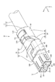
- FIG. 3 is a perspective view showing a step of externally fitting the sleeve to the sheath of the shielded electric wire.
- FIG. 3 is a plan view showing a state in which the sleeve is fitted over the sheath of the shielded electric wire. Plan view showing a state in which the braided wire is folded back on the sleeve.
- FIG. 3 is a perspective view showing a step of mounting the female terminal on the upper dielectric.
- FIG. 3 is a perspective view showing a process of assembling the upper dielectric and the lower dielectric.
- FIG. 3 is a perspective view showing a state in which the upper dielectric and the lower dielectric are assembled.
- FIG. 3 is a perspective view showing a step of inserting a dielectric into the tubular portion of the first outer conductor.
- FIG. 3 is a perspective view showing a state in which a dielectric is inserted in the tubular portion of the first outer conductor.
- FIG. 3 is a perspective view showing a step of connecting the first outer conductor and the second outer conductor.
- FIG. 3 is a perspective view showing a step of connecting the first outer conductor and the second outer conductor.
- Exploded perspective view showing the first outer conductor and the second outer conductor Bottom view showing female connector structure XVI-XVI line sectional view in FIG.
- FIG. 3 is a perspective view showing a state in which the sleeve is fitted over the sheath.
- FIG. 3 is a perspective view showing a process of mounting the male terminal on the upper dielectric.
- FIG. 3 is a perspective view showing a process of assembling the upper dielectric and the lower dielectric.
- FIG. 3 is a perspective view showing a state in which the upper dielectric and the lower dielectric are assembled.
- FIG. 3 is a perspective view showing a step of inserting a dielectric into the tubular portion of the first outer conductor.
- FIG. 3 is a perspective view showing a state in which a dielectric is inserted in the tubular portion of the first outer conductor.
- FIG. 3 is a perspective view showing a step of connecting the first outer conductor and the second outer conductor.
- FIG. 3 is a perspective view showing a step of connecting the first outer conductor and the second outer conductor. Exploded perspective view showing the first outer conductor and the second outer conductor
- FIGS. 1 to 16 A first embodiment in which the technology disclosed in this specification is applied to a female connector structure 10 (an example of a connector structure) will be described with reference to FIGS. 1 to 16.
- the female connector structure 10 according to the present embodiment is formed by connecting a female connector 12 (an example of a connector) to an end of a shielded electric wire 11.
- the Z direction is the upper direction
- the Y direction is the front
- the X direction is the left.
- a plurality of members only some of the members may be denoted by the reference numerals, and other members may not be denoted by the reference numerals.
- the shielded electric wire 11 surrounds the outer circumference of a plurality (two in the present embodiment) of the covered electric wire 13 with a braided wire 14 (an example of a shield part) made of a thin metal wire, and the outer circumference of the braided wire 14 is made of an insulating material. It is surrounded by a sheath 15.
- Each covered electric wire 13 includes a core wire 16 and an insulating coating 17 surrounding the outer circumference of the core wire 16.
- any metal such as copper, copper alloy, aluminum, aluminum alloy, or the like can be selected as necessary.
- the core wire 16 may be made of one metal element wire, or may be made of a stranded wire in which a plurality of metal element wires are twisted together.
- the insulating coating 17 and the sheath 15 are made of insulating synthetic resin.
- the end of the shielded electric wire 11 is subjected to a terminal treatment such as peeling, and the respective ends of the core wire 16, the insulation coating 17, and the braided wire 14 are exposed.
- the female connector 12 includes a female terminal 18 (an example of an inner conductor), an insulating dielectric 19 that surrounds the outer periphery of the female terminal 18, and an outer conductor 20 that surrounds the outer periphery of the dielectric 19.
- the outer conductor 20 includes a first outer conductor 33 and a second outer conductor 34 electrically connected to the first outer conductor 33.
- the female terminal 18 is formed by pressing a metal plate material into a predetermined shape.
- any metal such as copper, copper alloy, aluminum, and aluminum alloy can be selected as necessary.
- the female terminal 18 is connected to the end of each covered electric wire 13.
- the female terminal 18 is crimped so as to wind around the outer circumference of the insulating coating 17 of the covered electric wire 13, and the wire barrel 22 is crimped so as to wind around the outer circumference of the core wire 16 in front of the insulation barrel 21.
- a connecting tubular portion 23 that is connected to the front of the wire barrel 22 and into which a mating terminal (not shown) is inserted.
- An elastic contact piece 24 is arranged in the connecting tube portion 23. When the mating terminal is inserted into the connecting tubular portion 23, the mating terminal and the elastic contact piece 24 elastically contact with each other, whereby the mating terminal and the female terminal 18 are electrically connected. It is like this.
- the clip 25 As shown in FIG. 6, the two covered electric wires 13 led out from the ends of the sheath 15 are held by one clip 25, respectively.
- the clip 25 is formed by pressing a metal plate material into a predetermined shape.
- the clip 25 has a substantially W shape when viewed from the front-rear direction.
- the clip 25 is crimped so as to wind around the outer periphery of the insulating coating 17 of each covered electric wire 13.
- the clip 25 has crimping pieces 26 arranged at intervals in the front-rear direction. When the crimping pieces of the clip 25 are crimped to the two covered electric wires 13 by 26, the relative positions of the two covered electric wires 13 are held.
- the braided wire 14 is formed by braiding a plurality of thin metal wires in a tubular shape. The portion of the braided wire 14 exposed from the end of the sheath 15 is folded back to the end of the sheath 15 and overlapped on the outside of the sheath 15.
- the sleeve 27 As shown in FIGS. 3 to 5, the sleeve 27 is wound around the outer periphery of the sheath 15 outside the end of the sheath 15 and inside the braided wire 14 that is superposed on the end of the sheath 15. It is crimped.
- the sleeve 27 is formed by pressing a metal plate material into a predetermined shape.
- the sleeve 27 has an elongated plate shape. When viewed from the side, one end of the sleeve 27 in the longitudinal direction has a mountain shape, and the other end has a valley shape.
- the sleeve 27 is pressure-bonded to the outer circumference of the sheath 15 in a state where both ends of the sleeve 27 face each other with a gap.
- Dielectric 19 As shown in FIGS. 7 to 9, the periphery of the female terminal 18 is surrounded by the dielectric material 19.
- the dielectric 19 has a rectangular parallelepiped shape extending in the front-rear direction as a whole.
- the dielectric 19 includes a lower dielectric 28 that is opened upward and is arranged on the lower side, and an upper dielectric 29 that is assembled to the lower dielectric 28 from above.
- the lower dielectric 28 and the upper dielectric 29 are formed by injection molding an insulating synthetic resin.
- An elastically deformable lock receiving portion 31 formed at a position corresponding to the lock claw 30 of the lower dielectric 28 is elastically locked to the lock claw 30 protruding outward from the side edge of the upper dielectric 29.
- the lock receiving portion 31 has a substantially gate shape.
- a cavity 32 for accommodating the female terminal 18 is formed in the dielectric body 19 so as to extend in the front-rear direction.
- a plurality (two in the present embodiment) of cavities 32 are formed side by side in the left-right direction.
- the first outer conductor 33 is formed by pressing a metal plate material into a predetermined shape.
- any metal such as copper, copper alloy, aluminum, and aluminum alloy can be selected as necessary.
- the first outer conductor 33 has a tubular portion 35 that has a rectangular tubular shape that extends in the front-rear direction, a long plate-shaped member that is disposed behind the tubular portion 35 and that extends in the front-rear direction, and is braided wire that is folded back to the outer periphery of the sheath 15. It has a connecting plate portion 36 that is overlaid on 14, and a first connecting portion 37 that connects the tubular portion 35 and the connecting plate portion 36 in the front-rear direction.
- the inner shape of the tubular portion 35 is the same as or slightly larger than the outer shape of the dielectric 19.
- the dielectric 19 is inserted into the inside of the tubular portion 35 from the rear.
- the tubular portion 35 has a bottom wall 35B, a left side wall 35L extending upward from a left side edge of the bottom wall 35B, a right side wall 35R extending upward from a right side edge of the bottom wall 35B, and an upper wall 35U.
- the upper wall 35U has a right end edge of a left half portion 35UL extending rightward from an upper end edge of the left side wall 35L and a left end edge of a right half portion 35UR extending leftward from an upper end edge of the right side wall 35R at the center in the left-right direction.
- a substantially trapezoidal convex portion 38 and a substantially trapezoidal concave portion 39 are formed on the right end edge of the left half portion 35UL and the left end edge of the right half portion 35UR, respectively. By fitting with 39, expansion and deformation of the tubular portion 35 is suppressed.
- a locking piece 40 extending in the front-rear direction is formed at a position near the rear end portion of the left side wall 35L and the right side wall 35R of the tubular portion 35 so as to extend forward in a cantilever manner with the rear end portion as a base portion. ..
- the locking piece 40 is formed so as to extend inward in the left-right direction toward the front.
- a through hole 41 for cutting the locking piece 40 from the left side wall 35L and the right side wall 35R is formed.
- the locking piece 40 is formed so as to be elastically deformable in the left-right direction.
- the front end of the locking piece 40 is locked from the rear in a locking recess 42 formed at a position near the rear end of the dielectric 19 so that the dielectric 19 is held in the tubular portion 35 in a retaining state. It is supposed to be done.
- a mark 43 projecting downward is formed on the bottom wall 35B of the tubular portion 35 at a position slightly forward of the locking piece 40 and the through hole 41 and near the center in the left-right direction.
- the mark 43 is formed by tapping the bottom wall 35B of the tubular portion 35 downward.
- a first connecting portion 37 that extends obliquely downward and rearward is formed in a region that is approximately one-half from.
- the first connecting portion 37 has a curved surface shape that is convex downward when viewed from the rear.
- connection plate portion 36 is formed at the rear end edge of the first connecting portion 37 and extends rearward from around the center in the left-right direction.
- the connection plate portion 36 has a plate shape that extends in the front-rear direction in a slender shape.
- the upper surface and the lower surface of the connecting plate portion 36 are formed in a gentle arc shape that is convex downward.
- the second outer conductor 34 is formed by pressing a metal plate material into a predetermined shape.
- any metal such as copper, copper alloy, aluminum, and aluminum alloy can be selected as necessary.
- the second outer conductor 34 includes a front crimping portion 44 (an example of a cylinder crimping portion) that is crimped to the outer periphery of the tubular portion 35, a braided wire 14 folded back to the end of the sheath 15, and a connection plate that is superposed on the braided wire 14.
- a rear crimping portion 45 (an example of a shield crimping portion) that is crimped to the portion 36, and a second connecting portion 46 that connects the front crimping portion 44 and the rear crimping portion 45 to the front and rear are provided.
- the front crimping portion 44 includes an upper wall 44U, a left side wall 44L extending downward from a left side edge of the upper wall 44U, a right side wall 44R extending downward from a right side edge of the upper wall 44U, and a rear end of a lower end edge of the left side wall 44L.
- the left crimping piece 47L extends rightward from a portion near the end portion, and the right crimping piece 47R extends leftward from a portion near the front end portion of the lower end edge of the right side wall 44R.
- the upper wall 44U of the front crimping portion 44 covers the upper wall 35U of the tubular portion 35 from above, and the left side wall 44L of the front crimping portion 44 is the tubular portion 35.
- the left side wall 35L of the front crimping part 44 from the left side, the right side wall 44R of the front crimping part 44 covers the right side wall 35R of the tubular part 35 from the right side, and the left crimping piece 47L and the right crimping piece 47R of the front crimping part 44 are
- the bottom wall 35B of 35 is covered from below.
- a gap 48 is formed between the left crimping piece 47L and the right crimping piece 47R of the front crimping portion 44.
- the width dimension of the gap 48 in the front-rear direction is the same as or slightly larger than the width dimension of the mark 43 of the tubular portion 35 in the front-rear direction.
- the front end edge of the left crimping piece 47L can come into contact with the rear end edge of the mark 43 from the front. Further, the rear end edge of the right pressure-bonding piece 47R can come into contact with the front end edge of the mark 43 from behind. As a result, the tubular portion 35 and the front pressure-bonding portion 44 are positioned in the front-rear direction.
- the upper wall 44U of the front pressure-bonding portion 44 has a substantially square-shaped locking hole 49 as viewed from above.
- a lance of a connector housing (not shown) is adapted to be engaged with a hole edge portion of the engaging hole 49.
- the rear end of the upper wall 44U of the front crimping part 44, the rear end of the left side wall 44L of the front crimping part 44, and the rear end of the right side wall 44R of the front crimping part 44 have a second connection extending rearward.
- the portion 46 is formed.
- the second connecting portion 46 has a curved surface shape that is convex upward when viewed from the rear.
- a rear crimp portion 45 is provided behind the second connecting portion 46.
- the rear crimp portion 45 extends rearward from the rear end edge of the second connecting portion 46, the right crimp piece 51R extending downward from the right end edge of the substrate portion 50, and downward from the left end edge of the substrate portion 50.
- the left crimping piece 51L is included.
- the board portion 50 has a substantially rectangular shape and a curved shape that is convex upward when viewed from the rear.
- a plurality of (four in the present embodiment) protrusions 52 project inward in the radial direction of the shielded electric wire 11 at intervals in the circumferential direction of the shielded electric wire 11 at the rear end edge of the substrate portion 50. ..
- the protrusion 52 is bent substantially inward from the rear edge of the substrate 50 inward in the radial direction of the shielded electric wire 11.
- the protrusion 52 When the rear crimp portion 45 is crimped to the braided wire 14 and the connecting plate portion 36, the protrusion 52 is arranged at a position rearward of the rear end portion of the sleeve 27.
- the projecting dimension of the protrusion 52 inward in the radial direction of the shielded electric wire 11 is rearward with respect to the rear end edge of the sleeve 27 when the rear crimping portion 45 is crimped to the braided wire 14 and the connecting plate portion 36. It is set to be accessible from. Accordingly, when the shielded electric wire 11 is pulled rearward, the protrusion 52 abuts on the rear end edge of the sleeve 27, so that the shielded electric wire 11 can be prevented from moving rearward.
- a plurality of (two in the present embodiment) right crimping pieces 51R are extended from the right end edge of the substrate portion 50 at intervals in the front-rear direction.
- the right crimping pieces 51R are provided at the front end and the rear end of the right end edge of the substrate 50, respectively.
- a right locking portion 53R is formed at the tip of each right crimping piece 51R.
- the right locking portion 53R is formed in a shape in which the tip portion of the right crimping piece 51R is folded back to the inner surface side (braided wire 14 side).
- a left crimping piece 51L is extended from the left end edge of the board portion 50 at the center position in the front-rear direction.
- the width dimension of the left crimping piece 51L in the front-rear direction is set to be smaller than the distance between the pair of right crimping pieces 51R in the front-rear direction.
- a left locking portion 53L is formed at the tip of the left crimping piece 51L.
- the left locking portion 53L is formed in a shape in which the tip portion of the left crimping piece 51L is folded back to the inner surface side (braided wire 14 side).
- the mark 43 is accommodated in the gap 48 formed between the left crimping piece 47L and the right crimping piece 47R in a state where the front crimping portion 44 is crimped to the outer periphery of the tubular portion 35. It has become so.
- the lower surface of the mark 43 may be located above the lower surfaces of the left crimping piece 47L and the right crimping piece 47R, or the lower surface of the mark 43 and the lower surface of the left crimping piece 47L and the right crimping piece 47R are flush with each other. Alternatively, the lower surface of the mark 43 may protrude below the lower surfaces of the left crimping piece 47L and the right crimping piece 47R.
- the locking piece 40 and the through hole 41 of the tubular portion 35 are separated by the left side wall 44L and the right side wall 44R of the front crimping portion 44. , The left and right sides are covered from the outside. As a result, the dielectric 19 is not exposed from the through hole 41 of the tubular portion 35. As a result, noise generated in the female terminal 18 or the core wire 16 leaks to the outside from the through hole 41 of the tubular portion 35, or external noise enters the female terminal 18 or the core wire 16 from the through hole 41 of the tubular portion 35. Can be suppressed.
- the right locking portion 53R contacts the left edge of the connecting plate portion 36 from the direction along the radial direction of the shielded electric wire 11. Further, the left locking portion 53L abuts on the right side edge of the connection plate portion 36 from the direction along the radial direction of the shielded electric wire 11. As a result, the rear crimp portion 45 is prevented from expanding and deforming in the radial direction of the shielded electric wire 11.
- the upper end portion of the first connecting portion 37 As shown in FIG. 16, in a state where the front crimping portion 44 is crimped to the outer circumference of the tubular portion 35 and the rear crimping portion 45 is crimped to the braided wire 14 and the connecting plate portion 36, the upper end portion of the first connecting portion 37.
- the portion near the lower end of the second connecting portion 46 overlaps the portion closer to the lower portion in the radial direction of the shielded electric wire 11.
- the inner surface of the second connecting portion 46 is in close contact with the outer surface of the first connecting portion 37 at the portion where the second connecting portion 46 overlaps the outer side of the first connecting portion 37.
- the braided wire 14 is exposed from the sheath 15 by peeling the sheath 15 with a predetermined length.
- the braided wire 14 is cut into a predetermined length, and the covered electric wire 13 is exposed from the braided wire 14.
- the core wire 16 is exposed from the insulation coating 17 by peeling the insulation coating 17 with a predetermined length.
- the female terminal 18 is connected to the end of the coated electric wire 13 (see FIG. 3 ).
- the sleeve 27 is fitted on the end of the sheath 15.
- the braided wire 14 exposed from the end of the sheath 15 is folded back to cover the outer side of the sleeve 27 with the braided wire 14 in the radial direction of the shielded electric wire 11 (see FIG. 5 ).
- the clip 25 is fitted to the two covered electric wires 13 from below.
- the shielded electric wire 11 is turned upside down, and the female terminal 18 is placed on the upper wall of the turned upside-down upper dielectric 29 from above.
- the lower dielectric 28 is assembled to the upper dielectric 29 from above the upper dielectric 29.
- the lock receiving portion 31 of the lower dielectric 28 is elastically engaged with the lock claw 30 of the upper dielectric 29, so that the upper dielectric 29 and the lower dielectric 28 are integrally assembled (see FIG. 9 ).
- the shield wire 11 is turned upside down and the dielectric 19 is inserted into the tubular portion 35 of the first outer conductor 33 from the rear side.
- the locking piece 40 of the first outer conductor 33 is elastically locked to the locking recess 42 of the dielectric body 19 from the rear side, so that the dielectric body 19 is retained in the tubular portion 35 in a retaining state.
- the connection plate portion 36 of the first outer conductor 33 overlaps below the braided wire 14.
- the second outer conductor 34 is turned upside down, and the first outer conductor 33, and the braided wire 14 and the connecting plate portion 36 are placed on the second outer conductor 34 from above.
- the front crimp portion 44 is crimped to the outer circumference of the tubular portion 35
- the rear crimp portion 45 is crimped to the outer circumference of the braided wire 14 and the connection plate portion 36.
- the mark 43 formed on the bottom wall 35B of the tubular portion 35 is crimped to the mark.
- the crimping position of the second outer conductor 34 can be confirmed, so that the crimping process of the second outer conductor 34 can be made efficient.
- the mark 43 is housed in the gap 48 in the front-rear direction between the left crimping piece 47L and the right crimping piece 47R, it is possible to easily confirm that the second outer conductor 34 is crimped in the correct position. ..
- the left crimping piece 51L and the right crimping piece 51R are crimped so as to wind around the outer periphery of the braided wire 14 and the connection plate portion 36.
- the left locking portion 53L of the left crimping piece 51L is locked to the right edge of the connecting plate portion 36
- the right locking portion 53R of the right crimping piece 51R is locked to the left edge of the connecting plate portion 36.
- the rear crimping portion 45 is prevented from expanding and deforming.
- the braided wire 14, the first outer conductor 33, and the second outer conductor 34 are electrically connected by the rear crimping portion 45 crimping to the braided wire 14 and the connection plate portion 36.
- the second connecting portion 46 of the second outer conductor 34 is connected to the first outer conductor 33 of the first outer conductor 33. 1
- the pressure is applied to the outer circumference of the connecting portion 37. Accordingly, the inner surface of the second connecting portion 46 can be brought into close contact with the outer surface of the first connecting portion 37 at the portion where the second connecting portion 46 overlaps the outer side of the first connecting portion 37.
- the female connector 12 is a female connector in which the outer circumference of a coated wire 13 formed by surrounding an outer circumference of a core wire 16 with an insulating coating 17 is connected to an end portion of a shielded wire 11 surrounded by a braided wire 14. 12, a female terminal 18 connected to the core wire 16, an insulative dielectric 19 surrounding the female terminal 18, a tubular portion 35 surrounding the dielectric 19, and a connecting plate portion stacked on the braided wire 14.
- first outer conductor 33 having a first connecting portion 37 that connects the tubular portion 35 and the connecting plate portion 36, and the braided wire 14 and the connecting plate portion from the outside of the braided wire 14 and the connecting plate portion 36.
- the second outer conductor 34 is provided, and the mark 43 is provided at a predetermined position on the tubular portion 35, and the front crimp portion 44 is crimped to the tubular portion 35 with the mark 43 as a reference.
- the shielded electric wire 11 in which the outer circumference of the core wire 16 is surrounded by the insulating coating 17 and the outer circumference of the covered electric wire 13 is surrounded by the braided wire 14, and the shielded electric wire 11 Female terminal 18 connected to the core wire 16 exposed from the end of the wire, an insulating dielectric 19 surrounding the female terminal 18, a tubular portion 35 surrounding the dielectric 19, and a connecting plate overlaid on the braided wire 14.
- a first outer conductor 33 having a portion 36, a first connecting portion 37 connecting the tubular portion 35 and the connecting plate portion 36, and a braided wire 14 and a connecting plate from the outside of the braided wire 14 and the connecting plate portion 36.
- the second outer conductor 34 is included, and a mark 43 is provided at a predetermined position on the tubular portion 35.
- the front crimp portion 44 is crimped to the tubular portion 35 with the mark 43 as a reference.
- the front crimp portion 44 is crimped to the tubular portion 35 based on the relative positional relationship with the mark 43, whereby the first outer conductor is formed.
- the relative positional accuracy between 33 and the second outer conductor 34 can be improved.
- the mark 43 is formed so as to project from the tubular portion 35.
- the mark 43 and the front pressure-bonding portion 44 are fitted in a concavo-convex shape while the front pressure-bonding portion 44 is pressure-bonded to the tubular portion 35.
- the first outer conductor 33 and the second outer conductor 34 are reliably positioned, so that the relative positional accuracy between the first outer conductor 33 and the second outer conductor 34 is ensured. Can be improved.
- the male connector structure 110 (an example of a connector structure) according to this embodiment is formed by connecting a male connector 112 (an example of a connector) to the end of the shielded electric wire 11.
- the Z direction is the upper direction
- the Y direction is the front
- the X direction is the left.
- a plurality of members only some of the members may be denoted by the reference numerals, and other members may not be denoted by the reference numerals.
- the male connector 112 includes a male terminal 118 (an example of an inner conductor), an insulating dielectric 19 that surrounds the outer circumference of the male terminal 118, and an outer conductor 20 that surrounds the outer circumference of the dielectric 19.
- the outer conductor 20 includes a first outer conductor 33 and a second outer conductor 34 electrically connected to the first outer conductor 33.
- the male terminal 118 is formed by pressing a metal plate material into a predetermined shape.
- any metal such as copper, copper alloy, aluminum, aluminum alloy, or the like can be selected as necessary.
- the male terminal 118 is connected to the end of each covered electric wire 13.
- the male terminal 118 is an insulation barrel 21 that is crimped so as to wind around the outer periphery of the insulating coating 17 of the coated electric wire 13, and a wire barrel 22 that is connected in front of the insulation barrel 21 and is crimped so as to be wound around the outer periphery of the core wire 16.
- a male tab 123 that is connected to the front of the wire barrel 22 and is inserted into the connecting cylinder portion of the mating terminal (not shown) extends forward.
- the male tab 123 By inserting the male tab 123 into the connection tube portion, the mating terminal and the male terminal 118 are electrically connected.
- Dielectric 119 As shown in FIGS. 19 to 21, the periphery of the male terminal 118 is surrounded by the dielectric 119.
- the dielectric body 119 has a rectangular parallelepiped shape extending in the front-rear direction as a whole.
- the dielectric body 119 includes a lower dielectric body 128 which is opened upward and is arranged on the lower side, and an upper dielectric body 129 which is assembled to the lower dielectric body 128 from above.
- the lower dielectric 128 and the upper dielectric 129 are formed by injection molding an insulating synthetic resin.
- An elastically deformable lock receiving portion 131 formed at a position corresponding to the lock claw 130 of the lower dielectric 128 is elastically locked to the lock claw 130 protruding outward from the side edge of the upper dielectric 129.
- the lock receiving portion 131 has a substantially gate shape.
- the first outer conductor 133 is formed by pressing a metal plate material into a predetermined shape.
- the metal forming the first outer conductor 133 any metal such as copper, copper alloy, aluminum, and aluminum alloy can be selected as necessary.
- the first outer conductor 133 has a tubular portion 135 having a rectangular tubular shape extending in the front-rear direction, an elongated plate shape disposed behind the tubular portion 135 and extending in the front-rear direction, and braided wire folded around the outer periphery of the sheath 15. It has a connecting plate portion 36 that is overlaid with 14, and a first connecting portion 37 that connects the tubular portion 135 and the connecting plate portion 36 in the front-rear direction.
- the inner shape of the tubular portion 135 is the same as or slightly larger than the outer shape of the dielectric 119.
- a dielectric 119 is inserted into the inside of the tubular portion 135 from the rear (see FIG. 22).
- the tubular portion 135 includes a bottom wall 135B, a left side wall 135L extending upward from a left side edge of the bottom wall 135B, a right side wall 135R extending upward from a right side edge of the bottom wall 135B, and an upper wall 135U.
- the upper wall 135U includes a right end edge of a left half portion 135UL extending rightward from an upper end edge of the left side wall 135L and a left end edge of a right half portion 135UR extending leftward from an upper end edge of the right wall 135R. They are formed in a state where they are butted to each other in the vicinity.
- a convex portion 138 having a substantially trapezoidal shape and a concave portion 139 having a substantially trapezoidal shape are formed at the right end edge of the left half portion 135UL and the left end edge of the right half portion 135UR, respectively.
- a rear locking piece 140B extending in the front-rear direction is formed at a position near the rear end of the left side wall 135L and the right side wall 135R of the tubular portion 135 in a cantilevered manner with the rear end as a base. There is.
- the rear locking piece 140B is formed so as to extend inward in the left-right direction toward the front.
- a rear through hole 141B for cutting the rear locking piece 140B from the left side wall 135L and the right side wall 135R is formed near the rear locking piece 140B.
- the rear locking piece 140B is elastically deformable in the left-right direction.
- the front end of the rear locking piece 140B is locked from the rear in the rear locking recess 142B formed at a position near the rear end of the dielectric 119, so that the dielectric 119 is prevented from coming off in the tubular portion 135. It is supposed to be held in.
- a front locking piece 140F extending in the front-rear direction is formed near the center position in the front-rear direction of the left half portion 135UL of the tubular portion 135 so as to extend rearward in a cantilever manner with the front end as a base.
- the front locking piece 140F is formed so as to extend inward of the tubular portion 135 as it goes rearward.
- a front through hole 141F for cutting the front locking piece 140F from the bottom wall 135B is formed near the front locking piece 140F.
- the rear locking piece 140B is formed so as to be elastically deformable in the vertical direction.
- the front end of the front locking piece 140F is locked from the front in a front locking recess 142F formed near the center position of the dielectric 119 in the front-rear direction, so that the dielectric 119 is prevented from slipping out in the tubular portion 135. It is designed to be retained in the state.
- a lower mark 143L protruding downward is formed on the bottom wall 135B of the cylindrical portion 135 at a position slightly forward of the rear locking piece 140B and the rear through hole 141B and near the center in the left-right direction. There is.
- the lower mark 143L is formed by tapping the bottom wall 135B of the tubular portion 135 downward.
- a plurality of (two in the present embodiment) upper marks 143U projecting upward are provided at substantially the same position in the front-rear direction at the rear locking piece 140B and the rear through hole 141B. Are formed side by side at intervals.
- the upper mark 143U is formed by tapping the upper wall 135U of the tubular portion 135 upward.
- Each upper mark 143U has a columnar shape.
- the second outer conductor 134 is formed by pressing a metal plate material into a predetermined shape.
- any metal such as copper, copper alloy, aluminum, and aluminum alloy can be selected as necessary.
- the second outer conductor 134 includes a front crimping portion 144 (an example of a cylinder crimping portion) that is crimped to the outer periphery of the tubular portion 135, a braided wire 14 folded back to the end of the sheath 15, and a connection plate that is superposed on the braided wire 14.
- a rear crimping portion 145 (an example of a shield crimping portion) that is crimped to the portion 136, and a second connecting portion 146 that connects the front crimping portion 144 and the rear crimping portion 145 to the front and the rear are provided.
- the front crimp portion 144 includes an upper wall 144U, a left side wall 144L extending downward from a left side edge of the upper wall 144U, a right side wall 144R extending downward from a right side edge of the upper wall 144U, and a front end of a lower end edge of the left side wall 144L. It has a left crimping piece 147L extending rightward from the portion closer to the part, and a right crimping piece 147R extending leftward from the portion closer to the rear end of the upper edge of the right side wall 144R.
- the upper wall 144U of the front crimping portion 144 covers the upper wall 135U of the tubular portion 135 from above, and the left side wall 144L of the front crimping portion 144 is the tubular portion 135L.
- the bottom wall 135B of 135 is covered from above.
- a gap 148 (corresponding to a recess) is formed between the left crimping piece 147L and the right crimping piece 147R of the front crimping part 144.
- the width dimension of the gap 148 in the front-rear direction is equal to or slightly larger than the width dimension of the lower mark 143L of the tubular portion 135 in the front-rear direction.
- the lower mark 143L is adapted to be accommodated in the gap 148 formed between the left crimping piece 147L and the right crimping piece 147R in a state where the front crimping portion 144 is crimped to the outer periphery of the tubular portion 135.
- the lower surface of the lower mark 143L may be located above the lower surface of the left crimping piece 147L and the right crimping piece 147R, or the lower surface of the lower mark 143L and the lower surface of the left crimping piece 147L and the right crimping piece 147R are flush with each other.
- the upper surface of the lower mark 143L may protrude below the lower surfaces of the left crimping piece 147L and the right crimping piece 147R.
- the rear end edge of the left crimping piece 147L can come into contact with the front end edge of the upper mark 143U from the front. Further, the front end edge of the right pressure-bonding piece 147R can come into contact with the rear end edge of the upper mark 143U from the rear side. As a result, the tubular portion 135 and the front crimp portion 144 are positioned in the front-rear direction.
- a recess 160 is formed at a position near the rear end of the upper wall 144U of the front pressure-bonding portion 144 in a position corresponding to the upper mark 143U in a state where the front pressure-bonding portion 144 is pressure-bonded to the outer periphery of the tubular portion 135. ..
- the recess 160 is formed so as to penetrate the upper wall 144U.
- the inner shape of the recess 160 is circular when viewed from below, and is set to be the same as or slightly larger than the outer shape of the upper mark 143U.
- the upper marks 143U are each inserted into the inside of the recess 160 in a state in which the front crimp portion 144 is crimped to the outer periphery of the tubular portion 135.
- the upper surface of the upper mark 143U may be located below the upper surface of the upper wall 144U, the upper surface of the upper mark 143U may be flush with the upper surface of the upper wall 144U, or the upper surface of the upper mark 143U. May project above the upper surface of the upper wall 144U.
- the bottom wall 144B of the front crimp portion 144 has a locking hole 149 formed in a substantially square shape when viewed from above at a position slightly forward of the recess 160.
- a lance of a connector housing (not shown) is adapted to be engaged with an edge portion of the engaging hole 149.
- the rear locking piece 140B and the rear through hole 141B of the tubular portion 135 are left and right outside by the left side wall 144L and the right side wall 144R of the front crimping portion 144. It is adapted to be covered from one side (see also FIG. 24 and FIG. 25). As a result, the dielectric 119 is not exposed from the rear through hole 141B of the tubular portion 135.
- noise generated in the female terminal 18 or the core wire 16 leaks to the outside from the rear through hole 141B of the tubular portion 135, or external noise enters the female terminal 18 or the core wire 16 from the rear through hole 141B of the tubular portion 135. Can be suppressed.
- the front locking piece 140F and the front through hole 141F of the tubular portion 135 are covered from below by the upper wall 144U of the front crimp portion 144. (See also FIG. 24 and FIG. 25.
- the mark formed on the cylindrical portion 35 may be formed in a depressed concave shape, and the front pressure-bonding portion 44 may be formed with a convex portion that fits into the mark.
- the mark 43 may be separated from the right crimping piece 47R and the left crimping piece 47L in the front-rear direction.
- the number of the covered electric wires 13 surrounded by the sheath 15 and the braided wire 14 may be one, or may be three or more.
- the shield layer is not limited to the braided wire 14, and any material such as a metal foil or a resin tape to which a metal foil is attached can be appropriately selected.
- Female connector structure (an example of connector structure) 11: Shielded wire 12: Female connector (an example of connector) 13: Coated electric wire 14: Braided wire (an example of shield part) 15: sheath 16: core wire 17: insulating coating 18: female terminal (an example of inner conductor) 19: Dielectric 20: Outer conductor 21: Insulation barrel 22: Wire barrel 23: Connection cylinder 24: Elastic contact piece 25: Clip 26: Crimping piece 27: Sleeve 28: Lower dielectric 29: Upper dielectric 30: Lock Claw 31: Lock receiving portion 32: Cavity 33: First outer conductor 34: Second outer conductor 35: Cylindrical portion 35B: Bottom wall 35L: Left side wall 35R: Right side wall 35U: Upper wall 35UL: Left half portion 35UR: Right half Part 36: Connection plate part 37: First connecting part 38: Convex part 39: Recessed part 40: Locking piece 41: Through hole 42: Locking recessed part 43: Mark 44: Front crimping part (example of cylinder crimping
Abstract
A female connector 12 that connects to an end section of a shielded electrical wire 11 obtained by using braided wire 14 to surround the outer periphery of a coated electrical wire 13, which is obtained by surrounding the outer periphery of a core wire 16 with an insulating coating 17. The female connector 12 comprises: a female terminal 18 which connects with the core wire 16; an insulating dielectric body 19 which surrounds the female terminal 18; a first outer conductor body 33 having a cylinder part 35 which surrounds the dielectric body 19, a connection plate part 36 which is overlaid on the braided wire 14, and a first linking part 37 which links the cylinder part 35 and the connection plate part 36; and a second outer conductor body 34 having a rear crimped part 45 which crimps the braided wire 14 and the connection plate part 36 from the outside of the braided wire 14 and the connection plate part 36, a front crimped part 44 which crimps the cylinder part 35 from the outside of the cylinder part 35, and a second linking part 34 which links the rear crimped part 45 and the front crimped part 44. A mark 43 is provided at a prescribed position of the cylinder part 35, and the front crimped part 44 is crimped to the cylinder part 35 using the mark 43 as a reference.
Description
本明細書に開示された技術は、シールド電線の端末に接続されるコネクタに係る技術に関する。
The technology disclosed in this specification relates to a technology related to a connector connected to a terminal of a shielded electric wire.
シールド電線の端末に接続されるコネクタとして、特開2014-2974号公報に記載のものが知られている。シールド電線は、芯線の外周を絶縁被覆で包囲してなる被覆電線の外周を、シールド部で包囲してなる。コネクタは、芯線に接続される内部導体と、内部導体を覆う絶縁性の誘電体と、誘電体を覆う外部導体と、外部導体をシールド部に圧着する圧着部材と、を備える。
As a connector connected to the terminal of the shielded electric wire, the one described in JP-A-2014-2974 is known. The shielded electric wire is formed by surrounding the outer circumference of a covered electric wire in which the outer circumference of a core wire is surrounded by an insulating coating with a shield portion. The connector includes an inner conductor connected to the core wire, an insulating dielectric that covers the inner conductor, an outer conductor that covers the dielectric, and a crimp member that crimps the outer conductor to the shield part.
外部導体は接続片を有しており、接続片は、シールド部の内側に配されており、圧着部材は、シールド部の外側から、接続片とシールド部とを圧着している。これにより、シールド部と、接続片とが電気的に接続される。
The outer conductor has a connecting piece, the connecting piece is arranged inside the shield part, and the crimping member crimps the connecting piece and the shield part from the outside of the shield part. As a result, the shield part and the connecting piece are electrically connected.
上記のコネクタにおいては、外部導体と、シールド部とは、圧着部によって一括して圧着されることによって電気的に接続されている。このため、外部導体と圧着部との相対的な位置がずれると、外部導体とシールド部との間の電気的な接続信頼性が低下することが懸念される。すると、外部導体が十分なシールド性能を発揮することができなくなる虞が生じる。
In the above connector, the outer conductor and the shield part are electrically connected by being crimped together by the crimping part. For this reason, if the relative positions of the outer conductor and the crimping portion are deviated, there is concern that the electrical connection reliability between the outer conductor and the shield portion may deteriorate. Then, the outer conductor may not be able to exhibit a sufficient shield performance.
本明細書に開示された技術は上記のような事情に基づいて完成されたものであって、外部導体の組み付け精度が向上されたコネクタに係る技術を提供することを目的とする。
The technology disclosed in this specification has been completed based on the above circumstances, and an object thereof is to provide a technology related to a connector in which the assembly accuracy of the outer conductor is improved.
本明細書に開示された技術は、芯線の外周を絶縁被覆で包囲してなる被覆電線の外周を、シールド部で包囲してなるシールド電線の端部に接続されるコネクタであって、前記芯線に接続される内導体と、前記内導体を包囲する絶縁性の誘電体と、前記誘電体を包囲する筒部と、前記シールド部に重ねられる接続板部と、前記筒部と前記接続板部とを連結する第1連結部と、を有する第1外導体と、前記シールド部及び前記接続板部の外側から、前記シールド部及び前記接続板部を圧着するシールド圧着部と、前記筒部の外側から前記筒部を圧着する筒圧着部と、前記シールド圧着部と前記筒圧着部とを連結する第2連結部と、を有する第2外導体と、を備え、前記筒部には所定の位置にマークが設けられており、前記筒圧着部は前記マークを基準として前記筒部に圧着されている。
The technique disclosed in the present specification is a connector for connecting the outer circumference of a coated wire formed by surrounding the outer circumference of a core wire with an insulating coating to the end of a shielded wire surrounded by a shield portion, wherein the core wire is An inner conductor that is connected to the inner conductor, an insulating dielectric that surrounds the inner conductor, a tubular portion that surrounds the dielectric, a connection plate portion that overlaps the shield portion, the tubular portion and the connection plate portion. A first outer conductor having a first connecting portion for connecting the shield portion and the connecting plate portion from the outside of the shield portion and the connecting plate portion; A second outer conductor having a tube crimping section that crimps the tube section from the outside and a second connecting section that connects the shield crimping section and the tube crimping section is provided, and the tube section has a predetermined size. A mark is provided at the position, and the cylinder crimping portion is crimped to the cylinder portion with the mark as a reference.
また、本明細書に開示された技術は、コネクタ構造体であって、芯線の外周を絶縁被覆で包囲してなる被覆電線の外周を、シールド部で包囲してなるシールド電線と、前記シールド電線の端部から露出した前記芯線に接続される内導体と、前記内導体を包囲する絶縁性の誘電体と、前記誘電体を包囲する筒部と、前記シールド部に重ねられる接続板部と、前記筒部と前記接続板部とを連結する第1連結部と、を有する第1外導体と、前記シールド部及び前記接続板部の外側から、前記シールド部及び前記接続板部を圧着するシールド圧着部と、前記筒部の外側から前記筒部を圧着する筒圧着部と、前記シールド圧着部と前記筒圧着部とを連結する第2連結部と、を有する第2外導体と、を備え、前記筒部には所定の位置にマークが設けられており、前記筒圧着部は前記マークを基準として前記筒部に圧着されている。
In addition, the technique disclosed in the present specification is a connector structure, and a shielded wire in which the outer circumference of a covered wire in which the outer circumference of a core wire is surrounded by an insulating coating is surrounded by a shield part, and the shielded wire. An inner conductor connected to the core wire exposed from the end of, an insulating dielectric that surrounds the inner conductor, a tubular portion that surrounds the dielectric, and a connection plate portion that overlaps the shield portion, A first outer conductor having a first connecting portion connecting the tubular portion and the connecting plate portion, and a shield for crimping the shield portion and the connecting plate portion from the outside of the shield portion and the connecting plate portion. A second outer conductor having a crimping portion, a tubular crimping portion for crimping the tubular portion from the outside of the tubular portion, and a second connecting portion for coupling the shield crimping portion and the tubular crimping portion. A mark is provided at a predetermined position on the tubular portion, and the tubular crimping portion is crimped to the tubular portion with the mark as a reference.
上記の構成によれば、筒部に形成されたマークを基準とし、マークとの相対的な位置関係に基づいて筒圧着部を筒部に圧着することにより、第1外導体と、第2外導体との相対的な位置精度を向上させることができる。
According to the above configuration, with the mark formed on the tubular portion as a reference, the tubular crimping portion is crimped to the tubular portion based on the relative positional relationship with the mark, whereby the first outer conductor and the second outer conductor are provided. The positional accuracy relative to the conductor can be improved.
本明細書に開示された技術の実施態様としては以下の態様が好ましい。
The following aspects are preferable as the embodiments of the technology disclosed in this specification.
前記マークは前記筒部から突出して形成されている。
The mark is formed so as to project from the tubular portion.
上記の構成によれば、筒部に筒圧着部を圧着する際に、マークを視認しやすい。
According to the above configuration, it is easy to visually recognize the mark when crimping the tubular crimping portion to the tubular portion.
前記筒部に前記筒圧着部が圧着した状態で、前記マークと、前記筒圧着部とは、凹凸嵌合している。
The mark and the cylinder crimping portion are fitted in a concavo-convex shape in a state where the cylinder crimping portion is crimped to the cylinder portion.
上記の構成によれば、第1外導体と第2外導体とが確実に位置決めされるので、第1外導体と第2外導体との間の相対的な位置精度を確実に向上させることができる。
According to the above configuration, since the first outer conductor and the second outer conductor are reliably positioned, it is possible to reliably improve the relative positional accuracy between the first outer conductor and the second outer conductor. it can.
本明細書に開示された技術によれば、コネクタの外部導体の組み付け精度を向上させることができる。
According to the technique disclosed in this specification, the accuracy of assembling the outer conductor of the connector can be improved.
<実施形態1>
本明細書に開示された技術を雌コネクタ構造体10(コネクタ構造体の一例)に適用した実施形態1について、図1から図16を参照しつつ説明する。本実施形態に係る雌コネクタ構造体10は、シールド電線11の端末に雌コネクタ12(コネクタの一例)が接続されてなる。以下の説明においては、Z方向を上方とし、Y方向を前方とし、X方向を左方として説明する。複数の部材については、一部の部材にのみ符号を付し、他の部材については符号を省略する場合がある。 <Embodiment 1>
A first embodiment in which the technology disclosed in this specification is applied to a female connector structure 10 (an example of a connector structure) will be described with reference to FIGS. 1 to 16. Thefemale connector structure 10 according to the present embodiment is formed by connecting a female connector 12 (an example of a connector) to an end of a shielded electric wire 11. In the following description, the Z direction is the upper direction, the Y direction is the front, and the X direction is the left. Regarding a plurality of members, only some of the members may be denoted by the reference numerals, and other members may not be denoted by the reference numerals.
本明細書に開示された技術を雌コネクタ構造体10(コネクタ構造体の一例)に適用した実施形態1について、図1から図16を参照しつつ説明する。本実施形態に係る雌コネクタ構造体10は、シールド電線11の端末に雌コネクタ12(コネクタの一例)が接続されてなる。以下の説明においては、Z方向を上方とし、Y方向を前方とし、X方向を左方として説明する。複数の部材については、一部の部材にのみ符号を付し、他の部材については符号を省略する場合がある。 <Embodiment 1>
A first embodiment in which the technology disclosed in this specification is applied to a female connector structure 10 (an example of a connector structure) will be described with reference to FIGS. 1 to 16. The
シールド電線11
シールド電線11は、複数(本実施形態では2本)の被覆電線13の外周を、金属細線からなる編組線14(シールド部の一例)で包囲すると共に、編組線14の外周を絶縁材料からなるシース15で包囲してなる。各被覆電線13は、芯線16と、芯線16の外周を包囲する絶縁被覆17と、を備える。芯線16を構成する金属は、銅、銅合金、アルミニウム、アルミニウム合金等、必要に応じて任意の金属を選択することができる。芯線16は、1本の金属素線からなるものであってもよく、また、複数本の金属素線が撚り合わされた撚り線からなるものであってもよい。絶縁被覆17、及びシース15は、絶縁性の合成樹脂からなる。 Shieldedwire 11
The shieldedelectric wire 11 surrounds the outer circumference of a plurality (two in the present embodiment) of the covered electric wire 13 with a braided wire 14 (an example of a shield part) made of a thin metal wire, and the outer circumference of the braided wire 14 is made of an insulating material. It is surrounded by a sheath 15. Each covered electric wire 13 includes a core wire 16 and an insulating coating 17 surrounding the outer circumference of the core wire 16. As the metal forming the core wire 16, any metal such as copper, copper alloy, aluminum, aluminum alloy, or the like can be selected as necessary. The core wire 16 may be made of one metal element wire, or may be made of a stranded wire in which a plurality of metal element wires are twisted together. The insulating coating 17 and the sheath 15 are made of insulating synthetic resin.
シールド電線11は、複数(本実施形態では2本)の被覆電線13の外周を、金属細線からなる編組線14(シールド部の一例)で包囲すると共に、編組線14の外周を絶縁材料からなるシース15で包囲してなる。各被覆電線13は、芯線16と、芯線16の外周を包囲する絶縁被覆17と、を備える。芯線16を構成する金属は、銅、銅合金、アルミニウム、アルミニウム合金等、必要に応じて任意の金属を選択することができる。芯線16は、1本の金属素線からなるものであってもよく、また、複数本の金属素線が撚り合わされた撚り線からなるものであってもよい。絶縁被覆17、及びシース15は、絶縁性の合成樹脂からなる。 Shielded
The shielded
シールド電線11の端末においては、皮剥ぎ等の端末処理が施され、芯線16、絶縁被覆17、及び編組線14のそれぞれの端末が露出している。
The end of the shielded electric wire 11 is subjected to a terminal treatment such as peeling, and the respective ends of the core wire 16, the insulation coating 17, and the braided wire 14 are exposed.
雌コネクタ12
雌コネクタ12は、雌端子18(内導体の一例)と、雌端子18の外周を包囲する絶縁性の誘電体19と、誘電体19の外周を包囲する外導体20と、を備える。外導体20は、第1外導体33と、第1外導体33に電気的に接続された第2外導体34とを、有する。Female connector 12
Thefemale connector 12 includes a female terminal 18 (an example of an inner conductor), an insulating dielectric 19 that surrounds the outer periphery of the female terminal 18, and an outer conductor 20 that surrounds the outer periphery of the dielectric 19. The outer conductor 20 includes a first outer conductor 33 and a second outer conductor 34 electrically connected to the first outer conductor 33.
雌コネクタ12は、雌端子18(内導体の一例)と、雌端子18の外周を包囲する絶縁性の誘電体19と、誘電体19の外周を包囲する外導体20と、を備える。外導体20は、第1外導体33と、第1外導体33に電気的に接続された第2外導体34とを、有する。
The
雌端子18
雌端子18は、金属板材を所定の形状にプレス加工してなる。雌端子18を構成する金属としては、銅、銅合金、アルミニウム、アルミニウム合金等、必要に応じて任意の金属を選択することができる。雌端子18は、各被覆電線13の端末に接続されている。雌端子18は、被覆電線13の絶縁被覆17の外周に巻き付くように圧着するインシュレーションバレル21と、インシュレーションバレル21の前方に連なって芯線16の外周に巻き付くように圧着するワイヤーバレル22と、ワイヤーバレル22の前方に連なって、図示しない相手側端子が挿入される接続筒部23と、を有する。接続筒部23内には弾性接触片24が配されている。相手側端子が接続筒部23内に挿入されることにより、相手側端子と弾性接触片24とが弾性的に接触し、これにより、相手側端子と雌端子18とが電気的に接続されるようになっている。Female terminal 18
Thefemale terminal 18 is formed by pressing a metal plate material into a predetermined shape. As the metal forming the female terminal 18, any metal such as copper, copper alloy, aluminum, and aluminum alloy can be selected as necessary. The female terminal 18 is connected to the end of each covered electric wire 13. The female terminal 18 is crimped so as to wind around the outer circumference of the insulating coating 17 of the covered electric wire 13, and the wire barrel 22 is crimped so as to wind around the outer circumference of the core wire 16 in front of the insulation barrel 21. And a connecting tubular portion 23 that is connected to the front of the wire barrel 22 and into which a mating terminal (not shown) is inserted. An elastic contact piece 24 is arranged in the connecting tube portion 23. When the mating terminal is inserted into the connecting tubular portion 23, the mating terminal and the elastic contact piece 24 elastically contact with each other, whereby the mating terminal and the female terminal 18 are electrically connected. It is like this.
雌端子18は、金属板材を所定の形状にプレス加工してなる。雌端子18を構成する金属としては、銅、銅合金、アルミニウム、アルミニウム合金等、必要に応じて任意の金属を選択することができる。雌端子18は、各被覆電線13の端末に接続されている。雌端子18は、被覆電線13の絶縁被覆17の外周に巻き付くように圧着するインシュレーションバレル21と、インシュレーションバレル21の前方に連なって芯線16の外周に巻き付くように圧着するワイヤーバレル22と、ワイヤーバレル22の前方に連なって、図示しない相手側端子が挿入される接続筒部23と、を有する。接続筒部23内には弾性接触片24が配されている。相手側端子が接続筒部23内に挿入されることにより、相手側端子と弾性接触片24とが弾性的に接触し、これにより、相手側端子と雌端子18とが電気的に接続されるようになっている。
The
クリップ25
図6に示すように、シース15の端末から導出された2本の被覆電線13は、それぞれ、1つのクリップ25によって保持されている。クリップ25は、金属板材を所定の形状にプレス加工してなる。クリップ25は、前後方向から見て、略W字状をなしている。クリップ25は、各被覆電線13の絶縁被覆17の外周に巻き付くように圧着されるようになっている。クリップ25は、前後方向に間隔を空けて並ぶ圧着片26を有する。2本の被覆電線13にクリップ25の圧着片が26圧着することにより、2本の被覆電線13の相対的な位置が保持されるようになっている。Clip 25
As shown in FIG. 6, the two coveredelectric wires 13 led out from the ends of the sheath 15 are held by one clip 25, respectively. The clip 25 is formed by pressing a metal plate material into a predetermined shape. The clip 25 has a substantially W shape when viewed from the front-rear direction. The clip 25 is crimped so as to wind around the outer periphery of the insulating coating 17 of each covered electric wire 13. The clip 25 has crimping pieces 26 arranged at intervals in the front-rear direction. When the crimping pieces of the clip 25 are crimped to the two covered electric wires 13 by 26, the relative positions of the two covered electric wires 13 are held.
図6に示すように、シース15の端末から導出された2本の被覆電線13は、それぞれ、1つのクリップ25によって保持されている。クリップ25は、金属板材を所定の形状にプレス加工してなる。クリップ25は、前後方向から見て、略W字状をなしている。クリップ25は、各被覆電線13の絶縁被覆17の外周に巻き付くように圧着されるようになっている。クリップ25は、前後方向に間隔を空けて並ぶ圧着片26を有する。2本の被覆電線13にクリップ25の圧着片が26圧着することにより、2本の被覆電線13の相対的な位置が保持されるようになっている。
As shown in FIG. 6, the two covered
編組線14
編組線14は、複数の金属細線を筒状に編んでなる。編組線14のうちシース15の端末から露出した部分は、シース15の端末側に折り返されてシース15の外側に重ねられている。Braided wire 14
Thebraided wire 14 is formed by braiding a plurality of thin metal wires in a tubular shape. The portion of the braided wire 14 exposed from the end of the sheath 15 is folded back to the end of the sheath 15 and overlapped on the outside of the sheath 15.
編組線14は、複数の金属細線を筒状に編んでなる。編組線14のうちシース15の端末から露出した部分は、シース15の端末側に折り返されてシース15の外側に重ねられている。
The
スリーブ27
図3から図5に示すように、シース15の端末の外側であって、且つ、シース15の端末に重ねられた編組線14の内側には、スリーブ27がシース15の外周に巻き付くように圧着している。スリーブ27は金属板材を所定の形状にプレス加工してなる。スリーブ27は細長い板状をなしている。スリーブ27の長手方向の端部は、側方から見て、一方は山形状をなしており、他方は谷形状をなしている。スリーブ27の両端部が隙間を空けて対向した状態で、スリーブ27がシース15の外周に圧着するようになっている。Sleeve 27
As shown in FIGS. 3 to 5, thesleeve 27 is wound around the outer periphery of the sheath 15 outside the end of the sheath 15 and inside the braided wire 14 that is superposed on the end of the sheath 15. It is crimped. The sleeve 27 is formed by pressing a metal plate material into a predetermined shape. The sleeve 27 has an elongated plate shape. When viewed from the side, one end of the sleeve 27 in the longitudinal direction has a mountain shape, and the other end has a valley shape. The sleeve 27 is pressure-bonded to the outer circumference of the sheath 15 in a state where both ends of the sleeve 27 face each other with a gap.
図3から図5に示すように、シース15の端末の外側であって、且つ、シース15の端末に重ねられた編組線14の内側には、スリーブ27がシース15の外周に巻き付くように圧着している。スリーブ27は金属板材を所定の形状にプレス加工してなる。スリーブ27は細長い板状をなしている。スリーブ27の長手方向の端部は、側方から見て、一方は山形状をなしており、他方は谷形状をなしている。スリーブ27の両端部が隙間を空けて対向した状態で、スリーブ27がシース15の外周に圧着するようになっている。
As shown in FIGS. 3 to 5, the
誘電体19
図7から図9に示すように、雌端子18の周囲は、誘電体19によって包囲されるようになっている。誘電体19は、全体として、前後方向に延びる直方体形状をなしている。誘電体19は、上方に開口すると共に下側に配されるロア誘電体28と、ロア誘電体28に上方から組み付けられるアッパー誘電体29と、を備える。ロア誘電体28、及びアッパー誘電体29は、絶縁性の合成樹脂を射出成型してなる。アッパー誘電体29の側縁から外方に突出するロック爪30に、ロア誘電体28のうちロック爪30に対応する位置に形成された弾性変形可能なロック受け部31が弾性的に係止することにより、ロア誘電体28とアッパー誘電体29とが、一体に組み付けられるようになっている。ロック受け部31は略門形状をなしている。ロア誘電体28と、アッパー誘電体29とが組み付けられた状態で、誘電体19には、雌端子18が収容されるキャビティ32が、前後方向に延びて形成されるようになっている。本実施形態においては、複数(本実施形態では2つ)のキャビティ32が左右方向に並んで形成されている。Dielectric 19
As shown in FIGS. 7 to 9, the periphery of thefemale terminal 18 is surrounded by the dielectric material 19. The dielectric 19 has a rectangular parallelepiped shape extending in the front-rear direction as a whole. The dielectric 19 includes a lower dielectric 28 that is opened upward and is arranged on the lower side, and an upper dielectric 29 that is assembled to the lower dielectric 28 from above. The lower dielectric 28 and the upper dielectric 29 are formed by injection molding an insulating synthetic resin. An elastically deformable lock receiving portion 31 formed at a position corresponding to the lock claw 30 of the lower dielectric 28 is elastically locked to the lock claw 30 protruding outward from the side edge of the upper dielectric 29. As a result, the lower dielectric 28 and the upper dielectric 29 can be integrally assembled. The lock receiving portion 31 has a substantially gate shape. With the lower dielectric body 28 and the upper dielectric body 29 assembled, a cavity 32 for accommodating the female terminal 18 is formed in the dielectric body 19 so as to extend in the front-rear direction. In the present embodiment, a plurality (two in the present embodiment) of cavities 32 are formed side by side in the left-right direction.
図7から図9に示すように、雌端子18の周囲は、誘電体19によって包囲されるようになっている。誘電体19は、全体として、前後方向に延びる直方体形状をなしている。誘電体19は、上方に開口すると共に下側に配されるロア誘電体28と、ロア誘電体28に上方から組み付けられるアッパー誘電体29と、を備える。ロア誘電体28、及びアッパー誘電体29は、絶縁性の合成樹脂を射出成型してなる。アッパー誘電体29の側縁から外方に突出するロック爪30に、ロア誘電体28のうちロック爪30に対応する位置に形成された弾性変形可能なロック受け部31が弾性的に係止することにより、ロア誘電体28とアッパー誘電体29とが、一体に組み付けられるようになっている。ロック受け部31は略門形状をなしている。ロア誘電体28と、アッパー誘電体29とが組み付けられた状態で、誘電体19には、雌端子18が収容されるキャビティ32が、前後方向に延びて形成されるようになっている。本実施形態においては、複数(本実施形態では2つ)のキャビティ32が左右方向に並んで形成されている。
As shown in FIGS. 7 to 9, the periphery of the
第1外導体33
図10及び図14に示すように、第1外導体33は、金属板材を所定の形状にプレス加工してなる。第1外導体33を構成する金属は銅、銅合金、アルミニウム、アルミニウム合金等、任意の金属を必要に応じて選択できる。第1外導体33は、前後方向に延びる角筒状をなす筒部35と、筒部35の後方に配されて前後方向に延びる細長い板状をなすと共にシース15の外周に折り返された編組線14に重ねられる接続板部36と、筒部35と接続板部36とを前後に連結する第1連結部37と、を有する。 Firstouter conductor 33
As shown in FIGS. 10 and 14, the firstouter conductor 33 is formed by pressing a metal plate material into a predetermined shape. As the metal forming the first outer conductor 33, any metal such as copper, copper alloy, aluminum, and aluminum alloy can be selected as necessary. The first outer conductor 33 has a tubular portion 35 that has a rectangular tubular shape that extends in the front-rear direction, a long plate-shaped member that is disposed behind the tubular portion 35 and that extends in the front-rear direction, and is braided wire that is folded back to the outer periphery of the sheath 15. It has a connecting plate portion 36 that is overlaid on 14, and a first connecting portion 37 that connects the tubular portion 35 and the connecting plate portion 36 in the front-rear direction.
図10及び図14に示すように、第1外導体33は、金属板材を所定の形状にプレス加工してなる。第1外導体33を構成する金属は銅、銅合金、アルミニウム、アルミニウム合金等、任意の金属を必要に応じて選択できる。第1外導体33は、前後方向に延びる角筒状をなす筒部35と、筒部35の後方に配されて前後方向に延びる細長い板状をなすと共にシース15の外周に折り返された編組線14に重ねられる接続板部36と、筒部35と接続板部36とを前後に連結する第1連結部37と、を有する。 First
As shown in FIGS. 10 and 14, the first
筒部35の内形状は、誘電体19の外形状と同じか、やや大きく形成されている。筒部35の内部には、誘電体19が後方から挿入されるようになっている。筒部35は、底壁35Bと、底壁35Bの左側縁から上方に延びる左側壁35Lと、底壁35Bの右側縁から上方に延びる右側壁35Rと、上壁35Uとを、有する。上壁35Uは、左側壁35Lの上端縁から右方に延びる左半部35ULの右端縁と、右側壁35Rの上端縁から左方に延びる右半部35URの左端縁とが、左右方向について中央付近で互いに突き合わされた状態で、形成されている。左半部35ULの右端縁と、右半部35URの左端縁には、それぞれ、略台形状をなす凸部38と、略台形状をなす凹部39とが形成されており、凸部38と凹部39とが嵌合することにより、筒部35が拡開変形することが抑制されるようになっている。
The inner shape of the tubular portion 35 is the same as or slightly larger than the outer shape of the dielectric 19. The dielectric 19 is inserted into the inside of the tubular portion 35 from the rear. The tubular portion 35 has a bottom wall 35B, a left side wall 35L extending upward from a left side edge of the bottom wall 35B, a right side wall 35R extending upward from a right side edge of the bottom wall 35B, and an upper wall 35U. The upper wall 35U has a right end edge of a left half portion 35UL extending rightward from an upper end edge of the left side wall 35L and a left end edge of a right half portion 35UR extending leftward from an upper end edge of the right side wall 35R at the center in the left-right direction. They are formed in a state where they are butted to each other in the vicinity. A substantially trapezoidal convex portion 38 and a substantially trapezoidal concave portion 39 are formed on the right end edge of the left half portion 35UL and the left end edge of the right half portion 35UR, respectively. By fitting with 39, expansion and deformation of the tubular portion 35 is suppressed.
筒部35の左側壁35L及び右側壁35Rの後端部寄りの位置には、前後方向に延びる係止片40が、後端部を基部として、前方に片持ち状に延びて形成されている。係止片40は、前方に向かうに従って、左右方向について内方に延びて形成されている。係止片40の近傍には、係止片40を左側壁35L及び右側壁35Rから切り出すための貫通孔41が形成されている。係止片40は左右方向について弾性変形可能に形成されている。この係止片40の前端部が、誘電体19の後端部寄りの位置に形成された係止凹部42に後方から係止することにより、誘電体19が筒部35内において抜止状態で保持されるようになっている。
A locking piece 40 extending in the front-rear direction is formed at a position near the rear end portion of the left side wall 35L and the right side wall 35R of the tubular portion 35 so as to extend forward in a cantilever manner with the rear end portion as a base portion. .. The locking piece 40 is formed so as to extend inward in the left-right direction toward the front. In the vicinity of the locking piece 40, a through hole 41 for cutting the locking piece 40 from the left side wall 35L and the right side wall 35R is formed. The locking piece 40 is formed so as to be elastically deformable in the left-right direction. The front end of the locking piece 40 is locked from the rear in a locking recess 42 formed at a position near the rear end of the dielectric 19 so that the dielectric 19 is held in the tubular portion 35 in a retaining state. It is supposed to be done.
筒部35の底壁35Bには、係止片40及び貫通孔41よりもやや前方の位置であって、且つ、左右方向の中央付近に、下方に突出するマーク43が形成されている。マーク43は、筒部35の底壁35Bが下方に叩き出されて形成されている。
A mark 43 projecting downward is formed on the bottom wall 35B of the tubular portion 35 at a position slightly forward of the locking piece 40 and the through hole 41 and near the center in the left-right direction. The mark 43 is formed by tapping the bottom wall 35B of the tubular portion 35 downward.
筒部35の底壁35Bの後端縁と、筒部35の左側壁35Lの後端縁のうち下から略二分の一の領域と、筒部35の右側壁35Rの後端縁のうち下から略二分の一の領域とには、下斜め後方に延びる第1連結部37が形成されている。第1連結部37は、後方から見て、下方について凸状をなす曲面形状をなしている。
The rear end edge of the bottom wall 35B of the tubular portion 35, a region of the rear end edge of the left side wall 35L of the tubular portion 35 that is approximately one-half from below, and the lower end of the rear end edge of the right side wall 35R of the tubular portion 35. A first connecting portion 37 that extends obliquely downward and rearward is formed in a region that is approximately one-half from. The first connecting portion 37 has a curved surface shape that is convex downward when viewed from the rear.
第1連結部37の後端縁には、左右方向について中央付近から後方に延びる接続板部36が形成されている。接続板部36は前後方向に細長く延びる板状をなしている。接続板部36の上面及び下面は、下方について凸状をなす緩やかな円弧状をなしている。
A connection plate portion 36 is formed at the rear end edge of the first connecting portion 37 and extends rearward from around the center in the left-right direction. The connection plate portion 36 has a plate shape that extends in the front-rear direction in a slender shape. The upper surface and the lower surface of the connecting plate portion 36 are formed in a gentle arc shape that is convex downward.
第2外導体34
図13及び図14に示すように、第2外導体34は、金属板材を所定の形状にプレス加工してなる。第2外導体34を構成する金属は銅、銅合金、アルミニウム、アルミニウム合金等、任意の金属を必要に応じて選択できる。第2外導体34は、筒部35の外周に圧着する前圧着部44(筒圧着部の一例)と、シース15の端末に折り返された編組線14及びこの編組線14に重ねられた接続板部36に圧着する後圧着部45(シールド圧着部の一例)と、前圧着部44と後圧着部45とを前後に連結する第2連結部46と、を有する。 Secondouter conductor 34
As shown in FIGS. 13 and 14, the secondouter conductor 34 is formed by pressing a metal plate material into a predetermined shape. As the metal forming the second outer conductor 34, any metal such as copper, copper alloy, aluminum, and aluminum alloy can be selected as necessary. The second outer conductor 34 includes a front crimping portion 44 (an example of a cylinder crimping portion) that is crimped to the outer periphery of the tubular portion 35, a braided wire 14 folded back to the end of the sheath 15, and a connection plate that is superposed on the braided wire 14. A rear crimping portion 45 (an example of a shield crimping portion) that is crimped to the portion 36, and a second connecting portion 46 that connects the front crimping portion 44 and the rear crimping portion 45 to the front and rear are provided.
図13及び図14に示すように、第2外導体34は、金属板材を所定の形状にプレス加工してなる。第2外導体34を構成する金属は銅、銅合金、アルミニウム、アルミニウム合金等、任意の金属を必要に応じて選択できる。第2外導体34は、筒部35の外周に圧着する前圧着部44(筒圧着部の一例)と、シース15の端末に折り返された編組線14及びこの編組線14に重ねられた接続板部36に圧着する後圧着部45(シールド圧着部の一例)と、前圧着部44と後圧着部45とを前後に連結する第2連結部46と、を有する。 Second
As shown in FIGS. 13 and 14, the second
前圧着部44は、上壁44Uと、上壁44Uの左側縁から下方に延びる左側壁44Lと、上壁44Uの右側縁から下方に延びる右側壁44Rと、左側壁44Lの下端縁のうち後端部寄りの部分から右方に延びる左圧着片47Lと、右側壁44Rの下端縁のうち前端部寄りの部分から左方に延びる右圧着片47Rと、を有する。前圧着部44が筒部35の外周に圧着された状態では、前圧着部44の上壁44Uは筒部35の上壁35Uを上方から覆い、前圧着部44の左側壁44Lは筒部35の左側壁35Lを左方から覆い、前圧着部44の右側壁44Rは筒部35の右側壁35Rを右方から覆い、前圧着部44の左圧着片47Lと右圧着片47Rは、筒部35の底壁35Bを下方から覆っている。
The front crimping portion 44 includes an upper wall 44U, a left side wall 44L extending downward from a left side edge of the upper wall 44U, a right side wall 44R extending downward from a right side edge of the upper wall 44U, and a rear end of a lower end edge of the left side wall 44L. The left crimping piece 47L extends rightward from a portion near the end portion, and the right crimping piece 47R extends leftward from a portion near the front end portion of the lower end edge of the right side wall 44R. When the front crimping portion 44 is crimped to the outer periphery of the tubular portion 35, the upper wall 44U of the front crimping portion 44 covers the upper wall 35U of the tubular portion 35 from above, and the left side wall 44L of the front crimping portion 44 is the tubular portion 35. The left side wall 35L of the front crimping part 44 from the left side, the right side wall 44R of the front crimping part 44 covers the right side wall 35R of the tubular part 35 from the right side, and the left crimping piece 47L and the right crimping piece 47R of the front crimping part 44 are The bottom wall 35B of 35 is covered from below.
前後方向について、前圧着部44の左圧着片47Lと右圧着片47Rとの間には隙間48が形成されている。この隙間48の前後方向の幅寸法は、筒部35のマーク43の前後方向の幅寸法と、同じか、やや大きく形成されている。
In the front-back direction, a gap 48 is formed between the left crimping piece 47L and the right crimping piece 47R of the front crimping portion 44. The width dimension of the gap 48 in the front-rear direction is the same as or slightly larger than the width dimension of the mark 43 of the tubular portion 35 in the front-rear direction.
左圧着片47Lの前端縁は、マーク43の後端縁に対して前方から当接可能になっている。また、右圧着片47Rの後端縁は、マーク43の前端縁に対して後方から当接可能になっている。これにより、筒部35と、前圧着部44とは、前後方向について位置決めされるようになっている。
The front end edge of the left crimping piece 47L can come into contact with the rear end edge of the mark 43 from the front. Further, the rear end edge of the right pressure-bonding piece 47R can come into contact with the front end edge of the mark 43 from behind. As a result, the tubular portion 35 and the front pressure-bonding portion 44 are positioned in the front-rear direction.
前圧着部44の上壁44Uには、上方から見て略四角形状をなす係止孔49が貫通されている。この係止孔49の孔縁部に、図示しないコネクタハウジングのランスが係止するようになっている。
The upper wall 44U of the front pressure-bonding portion 44 has a substantially square-shaped locking hole 49 as viewed from above. A lance of a connector housing (not shown) is adapted to be engaged with a hole edge portion of the engaging hole 49.
前圧着部44の上壁44Uの後端縁と、前圧着部44の左側壁44Lの後端縁と、前圧着部44の右側壁44Rの後端縁とには、後方に延びる第2連結部46が形成されている。第2連結部46は、後方から見て、上方について凸状をなす曲面形状をなしている。
The rear end of the upper wall 44U of the front crimping part 44, the rear end of the left side wall 44L of the front crimping part 44, and the rear end of the right side wall 44R of the front crimping part 44 have a second connection extending rearward. The portion 46 is formed. The second connecting portion 46 has a curved surface shape that is convex upward when viewed from the rear.
第2連結部46の後方には後圧着部45が設けられている。後圧着部45は、第2連結部46の後端縁から後方に延びる基板部50と、基板部50の右端縁から下方に延びる右圧着片51Rと、基板部50の左端縁から下方に延びる左圧着片51Lと、を有する。
A rear crimp portion 45 is provided behind the second connecting portion 46. The rear crimp portion 45 extends rearward from the rear end edge of the second connecting portion 46, the right crimp piece 51R extending downward from the right end edge of the substrate portion 50, and downward from the left end edge of the substrate portion 50. The left crimping piece 51L is included.
基板部50は、略長方形状をなすと共に、後方から見て上方に凸状をなす曲面形状をなしている。基板部50の後端縁には、シールド電線11の周方向について間隔を空けて、複数(本実施形態では4つ)の突部52が、シールド電線11の径方向の内方に突出している。突部52は、基板部50の後端縁から、シールド電線11の径方向の内方に、略直角に屈曲している。
The board portion 50 has a substantially rectangular shape and a curved shape that is convex upward when viewed from the rear. A plurality of (four in the present embodiment) protrusions 52 project inward in the radial direction of the shielded electric wire 11 at intervals in the circumferential direction of the shielded electric wire 11 at the rear end edge of the substrate portion 50. .. The protrusion 52 is bent substantially inward from the rear edge of the substrate 50 inward in the radial direction of the shielded electric wire 11.
後圧着部45が編組線14及び接続板部36に圧着した状態において、突部52は、スリーブ27の後端部よりも後方の位置に配されるようになっている。突部52の、シールド電線11の径方向の内方への突出寸法は、後圧着部45が編組線14及び接続板部36に圧着した状態において、スリーブ27の後端縁に対して、後方から接触可能に設定されている。これにより、シールド電線11が後方に引っ張られた場合に、突部52が、スリーブ27の後端縁に当接することにより、シールド電線11が後方に移動することを抑制することができる。
When the rear crimp portion 45 is crimped to the braided wire 14 and the connecting plate portion 36, the protrusion 52 is arranged at a position rearward of the rear end portion of the sleeve 27. The projecting dimension of the protrusion 52 inward in the radial direction of the shielded electric wire 11 is rearward with respect to the rear end edge of the sleeve 27 when the rear crimping portion 45 is crimped to the braided wire 14 and the connecting plate portion 36. It is set to be accessible from. Accordingly, when the shielded electric wire 11 is pulled rearward, the protrusion 52 abuts on the rear end edge of the sleeve 27, so that the shielded electric wire 11 can be prevented from moving rearward.
基板部50の右端縁には、前後方向に間隔を空けて、複数(本実施形態では2つ)の右圧着片51Rが延出されている。右圧着片51Rは、それぞれ、基板部50の右端縁の前端部と、後端部とに、設けられている。それぞれの右圧着片51Rの先端部には、右係止部53Rが形成されている。右係止部53Rは、右圧着片51Rの先端部を、内面側(編組線14側)に折り返された形状に形成されている。
A plurality of (two in the present embodiment) right crimping pieces 51R are extended from the right end edge of the substrate portion 50 at intervals in the front-rear direction. The right crimping pieces 51R are provided at the front end and the rear end of the right end edge of the substrate 50, respectively. A right locking portion 53R is formed at the tip of each right crimping piece 51R. The right locking portion 53R is formed in a shape in which the tip portion of the right crimping piece 51R is folded back to the inner surface side (braided wire 14 side).
基板部50の左端縁には、前後方向の中央位置付記に、左圧着片51Lが延出されている。左圧着片51Lの前後方向の幅寸法は、一対の右圧着片51Rの前後方向についての間隔よりも小さく設定されている。左圧着片51Lの先端部には、左係止部53Lが形成されている。左係止部53Lは、左圧着片51Lの先端部を、内面側(編組線14側)に折り返された形状に形成されている。
A left crimping piece 51L is extended from the left end edge of the board portion 50 at the center position in the front-rear direction. The width dimension of the left crimping piece 51L in the front-rear direction is set to be smaller than the distance between the pair of right crimping pieces 51R in the front-rear direction. A left locking portion 53L is formed at the tip of the left crimping piece 51L. The left locking portion 53L is formed in a shape in which the tip portion of the left crimping piece 51L is folded back to the inner surface side (braided wire 14 side).
圧着構造
図15に示すように、前圧着部44が筒部35の外周に圧着した状態で、左圧着片47Lと右圧着片47Rとの間に形成された隙間48に、マーク43が収容されるようになっている。マーク43の下面が左圧着片47L及び右圧着片47Rの下面よりも上方に位置していてもよいし、マーク43の下面と左圧着片47L及び右圧着片47Rの下面とが面一であってもよいし、マーク43の下面が左圧着片47L及び右圧着片47Rの下面よりも下方に突出していてもよい。 Crimping Structure As shown in FIG. 15, themark 43 is accommodated in the gap 48 formed between the left crimping piece 47L and the right crimping piece 47R in a state where the front crimping portion 44 is crimped to the outer periphery of the tubular portion 35. It has become so. The lower surface of the mark 43 may be located above the lower surfaces of the left crimping piece 47L and the right crimping piece 47R, or the lower surface of the mark 43 and the lower surface of the left crimping piece 47L and the right crimping piece 47R are flush with each other. Alternatively, the lower surface of the mark 43 may protrude below the lower surfaces of the left crimping piece 47L and the right crimping piece 47R.
図15に示すように、前圧着部44が筒部35の外周に圧着した状態で、左圧着片47Lと右圧着片47Rとの間に形成された隙間48に、マーク43が収容されるようになっている。マーク43の下面が左圧着片47L及び右圧着片47Rの下面よりも上方に位置していてもよいし、マーク43の下面と左圧着片47L及び右圧着片47Rの下面とが面一であってもよいし、マーク43の下面が左圧着片47L及び右圧着片47Rの下面よりも下方に突出していてもよい。 Crimping Structure As shown in FIG. 15, the
図1に示すように、前圧着部44が筒部35の外周に圧着した状態で、筒部35の係止片40及び貫通孔41は、前圧着部44の左側壁44L及び右側壁44Rによって、左右方向について外方から覆われるようになっている。これにより、筒部35の貫通孔41から誘電体19が露出しないようになっている。この結果、雌端子18又は芯線16で発生したノイズが筒部35の貫通孔41から外部に漏洩したり、外部のノイズが筒部35の貫通孔41から雌端子18又は芯線16に侵入したりすることを抑制することができる。
As shown in FIG. 1, with the front crimping portion 44 crimped to the outer periphery of the tubular portion 35, the locking piece 40 and the through hole 41 of the tubular portion 35 are separated by the left side wall 44L and the right side wall 44R of the front crimping portion 44. , The left and right sides are covered from the outside. As a result, the dielectric 19 is not exposed from the through hole 41 of the tubular portion 35. As a result, noise generated in the female terminal 18 or the core wire 16 leaks to the outside from the through hole 41 of the tubular portion 35, or external noise enters the female terminal 18 or the core wire 16 from the through hole 41 of the tubular portion 35. Can be suppressed.
後圧着部45が編組線14及び接続板部36に圧着した状態において、右係止部53Rは、接続板部36の左側縁に、シールド電線11の径方向に沿った方向から当接する。また、左係止部53Lは、接続板部36の右側縁に、シールド電線11の径方向に沿った方向から当接する。これにより、後圧着部45が、シールド電線11の径方向について拡開変形することが抑制されるようになっている。
When the rear crimping portion 45 is crimped to the braided wire 14 and the connecting plate portion 36, the right locking portion 53R contacts the left edge of the connecting plate portion 36 from the direction along the radial direction of the shielded electric wire 11. Further, the left locking portion 53L abuts on the right side edge of the connection plate portion 36 from the direction along the radial direction of the shielded electric wire 11. As a result, the rear crimp portion 45 is prevented from expanding and deforming in the radial direction of the shielded electric wire 11.
図16に示すように、前圧着部44が筒部35の外周に圧着し、且つ、後圧着部45が編組線14及び接続板部36に圧着した状態において、第1連結部37の上端部寄りの部分には、第2連結部46の下端部寄りの部分が、シールド電線11の径方向について外側から重なるようになっている。本実施形態では、第1連結部37の外側に第2連結部46が重なった部分では、第2連結部46の内面は、第1連結部37の外面に密着している。
As shown in FIG. 16, in a state where the front crimping portion 44 is crimped to the outer circumference of the tubular portion 35 and the rear crimping portion 45 is crimped to the braided wire 14 and the connecting plate portion 36, the upper end portion of the first connecting portion 37. The portion near the lower end of the second connecting portion 46 overlaps the portion closer to the lower portion in the radial direction of the shielded electric wire 11. In the present embodiment, the inner surface of the second connecting portion 46 is in close contact with the outer surface of the first connecting portion 37 at the portion where the second connecting portion 46 overlaps the outer side of the first connecting portion 37.
雌コネクタ構造体10の組み付け工程
続いて、本実施形態に係る雌コネクタ構造体10の組み付け工程の一例について説明する。雌コネクタ構造体10の組み付け工程は以下の記載に限定されない。 Assembling Step ofFemale Connector Structure 10 Subsequently, an example of an assembling step of the female connector structure 10 according to the present embodiment will be described. The assembling process of the female connector structure 10 is not limited to the following description.
続いて、本実施形態に係る雌コネクタ構造体10の組み付け工程の一例について説明する。雌コネクタ構造体10の組み付け工程は以下の記載に限定されない。 Assembling Step of
シールド電線11の端末部分において、所定の長さでシース15を皮剥ぎすることにより、編組線14をシース15から露出させる。編組線14を所定の長さに切断し、編組線14から被覆電線13を露出させる。
At the end portion of the shielded electric wire 11, the braided wire 14 is exposed from the sheath 15 by peeling the sheath 15 with a predetermined length. The braided wire 14 is cut into a predetermined length, and the covered electric wire 13 is exposed from the braided wire 14.
被覆電線13の端末において、所定の長さで絶縁被覆17を皮剥ぎすることにより、芯線16を絶縁被覆17から露出させる。芯線16の外周にワイヤーバレル22を圧着させると共に、絶縁被覆17の外周にインシュレーションバレル21を圧着させることにより、被覆電線13の端末に雌端子18を接続する(図3参照)。
At the end of the covered electric wire 13, the core wire 16 is exposed from the insulation coating 17 by peeling the insulation coating 17 with a predetermined length. By crimping the wire barrel 22 to the outer periphery of the core wire 16 and the insulation barrel 21 to the outer periphery of the insulating coating 17, the female terminal 18 is connected to the end of the coated electric wire 13 (see FIG. 3 ).
図3及び図4に示すように、シース15の端部にスリーブ27を外嵌させる。シース15の端部から露出した編組線14を折り返すことにより、シールド電線11の径方向について、スリーブ27の外側に編組線14を被せる(図5参照)。
As shown in FIGS. 3 and 4, the sleeve 27 is fitted on the end of the sheath 15. The braided wire 14 exposed from the end of the sheath 15 is folded back to cover the outer side of the sleeve 27 with the braided wire 14 in the radial direction of the shielded electric wire 11 (see FIG. 5 ).
図6に示すように、2本の被覆電線13に、下方からクリップ25を嵌着させる。図7に示すように、シールド電線11の上下を反転させて、上下を反転させたアッパー誘電体29の上壁に、上方から雌端子18を載置する。図8に示すように、ロア誘電体28を、アッパー誘電体29の上方から、アッパー誘電体29に組み付ける。アッパー誘電体29のロック爪30に、ロア誘電体28のロック受け部31が弾性的に係合することにより、アッパー誘電体29とロア誘電体28とが一体に組み付けられる(図9参照)。
As shown in FIG. 6, the clip 25 is fitted to the two covered electric wires 13 from below. As shown in FIG. 7, the shielded electric wire 11 is turned upside down, and the female terminal 18 is placed on the upper wall of the turned upside-down upper dielectric 29 from above. As shown in FIG. 8, the lower dielectric 28 is assembled to the upper dielectric 29 from above the upper dielectric 29. The lock receiving portion 31 of the lower dielectric 28 is elastically engaged with the lock claw 30 of the upper dielectric 29, so that the upper dielectric 29 and the lower dielectric 28 are integrally assembled (see FIG. 9 ).
図10及び図11に示すように、シールド電線11の上下を反転させて、第1外導体33の筒部35内に、後方から誘電体19を挿入する。第1外導体33の係止片40が、後方から、誘電体19の係止凹部42に弾性的に係止することにより、誘電体19が筒部35内に抜け止め状態で保持される。このとき、第1外導体33の接続板部36は、編組線14の下方に重なるようになっている。
As shown in FIGS. 10 and 11, the shield wire 11 is turned upside down and the dielectric 19 is inserted into the tubular portion 35 of the first outer conductor 33 from the rear side. The locking piece 40 of the first outer conductor 33 is elastically locked to the locking recess 42 of the dielectric body 19 from the rear side, so that the dielectric body 19 is retained in the tubular portion 35 in a retaining state. At this time, the connection plate portion 36 of the first outer conductor 33 overlaps below the braided wire 14.
図13に示すように、第2外導体34の上下を反転させて、上方から、第1外導体33、並びに、編組線14及び接続板部36を、第2外導体34に載置する。前圧着部44を筒部35の外周に圧着させると共に、後圧着部45を編組線14及び接続板部36の外周に圧着させる。
As shown in FIG. 13, the second outer conductor 34 is turned upside down, and the first outer conductor 33, and the braided wire 14 and the connecting plate portion 36 are placed on the second outer conductor 34 from above. The front crimp portion 44 is crimped to the outer circumference of the tubular portion 35, and the rear crimp portion 45 is crimped to the outer circumference of the braided wire 14 and the connection plate portion 36.
前圧着部44については、筒部35の底壁35Bに形成されたマーク43を目印に圧着させる。底壁35Bに形成されたマーク43を目視することにより、第2外導体34の圧着位置を確認することができるので、第2外導体34の圧着工程を効率化することができる。更に、左圧着片47Lと右圧着片47Rとの前後方向の隙間48内にマーク43が収容されることにより、第2外導体34が正しい位置に圧着されたことを容易に確認することができる。
As for the front crimp portion 44, the mark 43 formed on the bottom wall 35B of the tubular portion 35 is crimped to the mark. By visually observing the mark 43 formed on the bottom wall 35B, the crimping position of the second outer conductor 34 can be confirmed, so that the crimping process of the second outer conductor 34 can be made efficient. Further, since the mark 43 is housed in the gap 48 in the front-rear direction between the left crimping piece 47L and the right crimping piece 47R, it is possible to easily confirm that the second outer conductor 34 is crimped in the correct position. ..
後圧着部45については、左圧着片51Lと、右圧着片51Rとを、編組線14及び接続板部36の外周に巻き付くように圧着させる。左圧着片51Lの左係止部53Lを接続板部36の右側縁に係止させると共に、右圧着片51Rの右係止部53Rを接続板部36の左側縁に係止させる。これにより、後圧着部45が拡開変形することが抑制されるようになっている。後圧着部45が、編組線14及び接続板部36に圧着することにより、編組線14と、第1外導体33と、第2外導体34とが電気的に接続される。
As for the rear crimping portion 45, the left crimping piece 51L and the right crimping piece 51R are crimped so as to wind around the outer periphery of the braided wire 14 and the connection plate portion 36. The left locking portion 53L of the left crimping piece 51L is locked to the right edge of the connecting plate portion 36, and the right locking portion 53R of the right crimping piece 51R is locked to the left edge of the connecting plate portion 36. As a result, the rear crimping portion 45 is prevented from expanding and deforming. The braided wire 14, the first outer conductor 33, and the second outer conductor 34 are electrically connected by the rear crimping portion 45 crimping to the braided wire 14 and the connection plate portion 36.
第2外導体34の前圧着部44及び後圧着部45を第1外導体33に圧着する工程と同じ工程において、第2外導体34の第2連結部46を、第1外導体33の第1連結部37の外周に圧着させる。これにより、第1連結部37の外側に第2連結部46が重なっている部分において、第2連結部46の内面を、第1連結部37の外面に密着させることができる。以上により、コネクタ構造体が完成する。
In the same step as the step of crimping the front crimp portion 44 and the rear crimp portion 45 of the second outer conductor 34 to the first outer conductor 33, the second connecting portion 46 of the second outer conductor 34 is connected to the first outer conductor 33 of the first outer conductor 33. 1 The pressure is applied to the outer circumference of the connecting portion 37. Accordingly, the inner surface of the second connecting portion 46 can be brought into close contact with the outer surface of the first connecting portion 37 at the portion where the second connecting portion 46 overlaps the outer side of the first connecting portion 37. With the above, the connector structure is completed.
実施形態の作用効果
続いて、本実施形態の作用効果について説明する。本実施形態に係る雌コネクタ12は、芯線16の外周を絶縁被覆で17包囲してなる被覆電線13の外周を、編組線14で包囲してなるシールド電線11の端部に接続される雌コネクタ12であって、芯線16に接続される雌端子18と、雌端子18を包囲する絶縁性の誘電体19と、誘電体19を包囲する筒部35と、編組線14に重ねられる接続板部36と、筒部35と接続板部36とを連結する第1連結部37と、を有する第1外導体33と、編組線14及び接続板部36の外側から、編組線14及び接続板部36を圧着する後圧着部45と、筒部35の外側から筒部35を圧着する前圧着部44と、後圧着部45と前圧着部44とを連結する第2連結部46と、を有する第2外導体34と、を備え、筒部35には所定の位置にマーク43が設けられており、前圧着部44はマーク43を基準として筒部35に圧着されている。 Operation and Effect of Embodiment Next, the operation and effect of the present embodiment will be described. Thefemale connector 12 according to the present embodiment is a female connector in which the outer circumference of a coated wire 13 formed by surrounding an outer circumference of a core wire 16 with an insulating coating 17 is connected to an end portion of a shielded wire 11 surrounded by a braided wire 14. 12, a female terminal 18 connected to the core wire 16, an insulative dielectric 19 surrounding the female terminal 18, a tubular portion 35 surrounding the dielectric 19, and a connecting plate portion stacked on the braided wire 14. 36, a first outer conductor 33 having a first connecting portion 37 that connects the tubular portion 35 and the connecting plate portion 36, and the braided wire 14 and the connecting plate portion from the outside of the braided wire 14 and the connecting plate portion 36. A rear crimping portion 45 that crimps 36, a front crimping portion 44 that crimps the tubular portion 35 from the outside of the tubular portion 35, and a second connecting portion 46 that couples the rear crimping portion 45 and the front crimping portion 44. The second outer conductor 34 is provided, and the mark 43 is provided at a predetermined position on the tubular portion 35, and the front crimp portion 44 is crimped to the tubular portion 35 with the mark 43 as a reference.
続いて、本実施形態の作用効果について説明する。本実施形態に係る雌コネクタ12は、芯線16の外周を絶縁被覆で17包囲してなる被覆電線13の外周を、編組線14で包囲してなるシールド電線11の端部に接続される雌コネクタ12であって、芯線16に接続される雌端子18と、雌端子18を包囲する絶縁性の誘電体19と、誘電体19を包囲する筒部35と、編組線14に重ねられる接続板部36と、筒部35と接続板部36とを連結する第1連結部37と、を有する第1外導体33と、編組線14及び接続板部36の外側から、編組線14及び接続板部36を圧着する後圧着部45と、筒部35の外側から筒部35を圧着する前圧着部44と、後圧着部45と前圧着部44とを連結する第2連結部46と、を有する第2外導体34と、を備え、筒部35には所定の位置にマーク43が設けられており、前圧着部44はマーク43を基準として筒部35に圧着されている。 Operation and Effect of Embodiment Next, the operation and effect of the present embodiment will be described. The
また、本実施形態に係る雌コネクタ構造体10は、芯線16の外周を絶縁被覆17で包囲してなる被覆電線13の外周を、編組線14で包囲してなるシールド電線11と、シールド電線11の端部から露出した芯線16に接続される雌端子18と、雌端子18を包囲する絶縁性の誘電体19と、誘電体19を包囲する筒部35と、編組線14に重ねられる接続板部36と、筒部35と接続板部36とを連結する第1連結部37と、を有する第1外導体33と、編組線14及び接続板部36の外側から、編組線14及び接続板部36を圧着する後圧着部45と、筒部35の外側から筒部35を圧着する前圧着部44と、後圧着部45と前圧着部44とを連結する第2連結部46と、を有する第2外導体34と、を備え、筒部35には所定の位置にマーク43が設けられており、前圧着部44はマーク43を基準として筒部35に圧着されている。
Further, in the female connector structure 10 according to the present embodiment, the shielded electric wire 11 in which the outer circumference of the core wire 16 is surrounded by the insulating coating 17 and the outer circumference of the covered electric wire 13 is surrounded by the braided wire 14, and the shielded electric wire 11 Female terminal 18 connected to the core wire 16 exposed from the end of the wire, an insulating dielectric 19 surrounding the female terminal 18, a tubular portion 35 surrounding the dielectric 19, and a connecting plate overlaid on the braided wire 14. A first outer conductor 33 having a portion 36, a first connecting portion 37 connecting the tubular portion 35 and the connecting plate portion 36, and a braided wire 14 and a connecting plate from the outside of the braided wire 14 and the connecting plate portion 36. A rear crimping portion 45 for crimping the portion 36, a front crimping portion 44 for crimping the tubular portion 35 from the outside of the tubular portion 35, and a second connecting portion 46 for coupling the rear crimping portion 45 and the front crimping portion 44. The second outer conductor 34 is included, and a mark 43 is provided at a predetermined position on the tubular portion 35. The front crimp portion 44 is crimped to the tubular portion 35 with the mark 43 as a reference.
上記の構成によれば、筒部35に形成されたマーク43を基準とし、マーク43との相対的な位置関係に基づいて前圧着部44を筒部35に圧着することにより、第1外導体33と、第2外導体34との相対的な位置精度を向上させることができる。
According to the above configuration, with the mark 43 formed on the tubular portion 35 as a reference, the front crimp portion 44 is crimped to the tubular portion 35 based on the relative positional relationship with the mark 43, whereby the first outer conductor is formed. The relative positional accuracy between 33 and the second outer conductor 34 can be improved.
また、本実施形態によれば、マーク43は筒部35から突出して形成されている。
Further, according to this embodiment, the mark 43 is formed so as to project from the tubular portion 35.
上記の構成によれば、筒部35に前圧着部44を圧着する際に、マーク43を視認しやすいので、雌コネクタ12の組み付け作業の効率を向上させることができる。
According to the above configuration, when the front crimp portion 44 is crimped to the tubular portion 35, the mark 43 is easily visible, so that the efficiency of the assembling work of the female connector 12 can be improved.
また、本実施形態によれば、筒部35に前圧着部44が圧着した状態で、マーク43と、前圧着部44とは、凹凸嵌合している。
Further, according to the present embodiment, the mark 43 and the front pressure-bonding portion 44 are fitted in a concavo-convex shape while the front pressure-bonding portion 44 is pressure-bonded to the tubular portion 35.
上記の構成によれば、第1外導体33と第2外導体34とが確実に位置決めされるので、第1外導体33と第2外導体34との間の相対的な位置精度を確実に向上させることができる。
According to the above configuration, the first outer conductor 33 and the second outer conductor 34 are reliably positioned, so that the relative positional accuracy between the first outer conductor 33 and the second outer conductor 34 is ensured. Can be improved.
<実施形態2>
本明細書に開示された技術に係る実施形態2について、図17から図26を参照しつつ説明する。本実施形態に係る雄コネクタ構造体110(コネクタ構造体の一例)は、シールド電線11の端末に雄コネクタ112(コネクタの一例)が接続されてなる。以下の説明においては、Z方向を上方とし、Y方向を前方とし、X方向を左方として説明する。複数の部材については、一部の部材にのみ符号を付し、他の部材については符号を省略する場合がある。 <Embodiment 2>
A second embodiment according to the technology disclosed in this specification will be described with reference to FIGS. 17 to 26. The male connector structure 110 (an example of a connector structure) according to this embodiment is formed by connecting a male connector 112 (an example of a connector) to the end of the shieldedelectric wire 11. In the following description, the Z direction is the upper direction, the Y direction is the front, and the X direction is the left. Regarding a plurality of members, only some of the members may be denoted by the reference numerals, and other members may not be denoted by the reference numerals.
本明細書に開示された技術に係る実施形態2について、図17から図26を参照しつつ説明する。本実施形態に係る雄コネクタ構造体110(コネクタ構造体の一例)は、シールド電線11の端末に雄コネクタ112(コネクタの一例)が接続されてなる。以下の説明においては、Z方向を上方とし、Y方向を前方とし、X方向を左方として説明する。複数の部材については、一部の部材にのみ符号を付し、他の部材については符号を省略する場合がある。 <Embodiment 2>
A second embodiment according to the technology disclosed in this specification will be described with reference to FIGS. 17 to 26. The male connector structure 110 (an example of a connector structure) according to this embodiment is formed by connecting a male connector 112 (an example of a connector) to the end of the shielded
雄コネクタ112
雄コネクタ112は、雄端子118(内導体の一例)と、雄端子118の外周を包囲する絶縁性の誘電体19と、誘電体19の外周を包囲する外導体20と、を備える。外導体20は、第1外導体33と、第1外導体33に電気的に接続された第2外導体34とを、有する。Male connector 112
Themale connector 112 includes a male terminal 118 (an example of an inner conductor), an insulating dielectric 19 that surrounds the outer circumference of the male terminal 118, and an outer conductor 20 that surrounds the outer circumference of the dielectric 19. The outer conductor 20 includes a first outer conductor 33 and a second outer conductor 34 electrically connected to the first outer conductor 33.
雄コネクタ112は、雄端子118(内導体の一例)と、雄端子118の外周を包囲する絶縁性の誘電体19と、誘電体19の外周を包囲する外導体20と、を備える。外導体20は、第1外導体33と、第1外導体33に電気的に接続された第2外導体34とを、有する。
The
雄端子118
図18に示すように、雄端子118は、金属板材を所定の形状にプレス加工してなる。雄端子118を構成する金属としては、銅、銅合金、アルミニウム、アルミニウム合金等、必要に応じて任意の金属を選択することができる。雄端子118は、各被覆電線13の端末に接続されている。雄端子118は、被覆電線13の絶縁被覆17の外周に巻き付くように圧着するインシュレーションバレル21と、インシュレーションバレル21の前方に連なって芯線16の外周に巻き付くように圧着するワイヤーバレル22と、ワイヤーバレル22の前方に連なって、図示しない相手側端子の接続筒部内に挿入される雄タブ123が前方に延出している。雄タブ123が接続筒部内に挿入されることにより、相手側端子と雄端子118とが電気的に接続されるようになっている。Male terminal 118
As shown in FIG. 18, themale terminal 118 is formed by pressing a metal plate material into a predetermined shape. As the metal forming the male terminal 118, any metal such as copper, copper alloy, aluminum, aluminum alloy, or the like can be selected as necessary. The male terminal 118 is connected to the end of each covered electric wire 13. The male terminal 118 is an insulation barrel 21 that is crimped so as to wind around the outer periphery of the insulating coating 17 of the coated electric wire 13, and a wire barrel 22 that is connected in front of the insulation barrel 21 and is crimped so as to be wound around the outer periphery of the core wire 16. Then, a male tab 123 that is connected to the front of the wire barrel 22 and is inserted into the connecting cylinder portion of the mating terminal (not shown) extends forward. By inserting the male tab 123 into the connection tube portion, the mating terminal and the male terminal 118 are electrically connected.
図18に示すように、雄端子118は、金属板材を所定の形状にプレス加工してなる。雄端子118を構成する金属としては、銅、銅合金、アルミニウム、アルミニウム合金等、必要に応じて任意の金属を選択することができる。雄端子118は、各被覆電線13の端末に接続されている。雄端子118は、被覆電線13の絶縁被覆17の外周に巻き付くように圧着するインシュレーションバレル21と、インシュレーションバレル21の前方に連なって芯線16の外周に巻き付くように圧着するワイヤーバレル22と、ワイヤーバレル22の前方に連なって、図示しない相手側端子の接続筒部内に挿入される雄タブ123が前方に延出している。雄タブ123が接続筒部内に挿入されることにより、相手側端子と雄端子118とが電気的に接続されるようになっている。
As shown in FIG. 18, the
誘電体119
図19から図21に示すように、雄端子118の周囲は、誘電体119によって包囲されるようになっている。誘電体119は、全体として、前後方向に延びる直方体形状をなしている。誘電体119は、上方に開口すると共に下側に配されるロア誘電体128と、ロア誘電体128に上方から組み付けられるアッパー誘電体129と、を備える。ロア誘電体128、及びアッパー誘電体129は、絶縁性の合成樹脂を射出成型してなる。アッパー誘電体129の側縁から外方に突出するロック爪130に、ロア誘電体128のうちロック爪130に対応する位置に形成された弾性変形可能なロック受け部131が弾性的に係止することにより、ロア誘電体128とアッパー誘電体129とが、一体に組み付けられるようになっている。ロック受け部131は略門形状をなしている。ロア誘電体128と、アッパー誘電体129とが組み付けられた状態で、誘電体119には、雄端子118が収容されるキャビティ132が、前後方向に延びて形成されるようになっている。本実施形態においては、複数(本実施形態では2つ)のキャビティ132が左右方向に並んで形成されている。 Dielectric 119
As shown in FIGS. 19 to 21, the periphery of themale terminal 118 is surrounded by the dielectric 119. The dielectric body 119 has a rectangular parallelepiped shape extending in the front-rear direction as a whole. The dielectric body 119 includes a lower dielectric body 128 which is opened upward and is arranged on the lower side, and an upper dielectric body 129 which is assembled to the lower dielectric body 128 from above. The lower dielectric 128 and the upper dielectric 129 are formed by injection molding an insulating synthetic resin. An elastically deformable lock receiving portion 131 formed at a position corresponding to the lock claw 130 of the lower dielectric 128 is elastically locked to the lock claw 130 protruding outward from the side edge of the upper dielectric 129. As a result, the lower dielectric 128 and the upper dielectric 129 are integrally assembled. The lock receiving portion 131 has a substantially gate shape. With the lower dielectric 128 and the upper dielectric 129 assembled, the dielectric 119 is formed with a cavity 132 for accommodating the male terminal 118, extending in the front-rear direction. In the present embodiment, a plurality (two in the present embodiment) of cavities 132 are formed side by side in the left-right direction.
図19から図21に示すように、雄端子118の周囲は、誘電体119によって包囲されるようになっている。誘電体119は、全体として、前後方向に延びる直方体形状をなしている。誘電体119は、上方に開口すると共に下側に配されるロア誘電体128と、ロア誘電体128に上方から組み付けられるアッパー誘電体129と、を備える。ロア誘電体128、及びアッパー誘電体129は、絶縁性の合成樹脂を射出成型してなる。アッパー誘電体129の側縁から外方に突出するロック爪130に、ロア誘電体128のうちロック爪130に対応する位置に形成された弾性変形可能なロック受け部131が弾性的に係止することにより、ロア誘電体128とアッパー誘電体129とが、一体に組み付けられるようになっている。ロック受け部131は略門形状をなしている。ロア誘電体128と、アッパー誘電体129とが組み付けられた状態で、誘電体119には、雄端子118が収容されるキャビティ132が、前後方向に延びて形成されるようになっている。本実施形態においては、複数(本実施形態では2つ)のキャビティ132が左右方向に並んで形成されている。 Dielectric 119
As shown in FIGS. 19 to 21, the periphery of the
第1外導体133
図22及び図26に示すように、第1外導体133は、金属板材を所定の形状にプレス加工してなる。第1外導体133を構成する金属は銅、銅合金、アルミニウム、アルミニウム合金等、任意の金属を必要に応じて選択できる。第1外導体133は、前後方向に延びる角筒状をなす筒部135と、筒部135の後方に配されて前後方向に延びる細長い板状をなすと共にシース15の外周に折り返された編組線14に重ねられる接続板部36と、筒部135と接続板部36とを前後に連結する第1連結部37と、を有する。 Firstouter conductor 133
As shown in FIGS. 22 and 26, the firstouter conductor 133 is formed by pressing a metal plate material into a predetermined shape. As the metal forming the first outer conductor 133, any metal such as copper, copper alloy, aluminum, and aluminum alloy can be selected as necessary. The first outer conductor 133 has a tubular portion 135 having a rectangular tubular shape extending in the front-rear direction, an elongated plate shape disposed behind the tubular portion 135 and extending in the front-rear direction, and braided wire folded around the outer periphery of the sheath 15. It has a connecting plate portion 36 that is overlaid with 14, and a first connecting portion 37 that connects the tubular portion 135 and the connecting plate portion 36 in the front-rear direction.
図22及び図26に示すように、第1外導体133は、金属板材を所定の形状にプレス加工してなる。第1外導体133を構成する金属は銅、銅合金、アルミニウム、アルミニウム合金等、任意の金属を必要に応じて選択できる。第1外導体133は、前後方向に延びる角筒状をなす筒部135と、筒部135の後方に配されて前後方向に延びる細長い板状をなすと共にシース15の外周に折り返された編組線14に重ねられる接続板部36と、筒部135と接続板部36とを前後に連結する第1連結部37と、を有する。 First
As shown in FIGS. 22 and 26, the first
筒部135の内形状は、誘電体119の外形状と同じか、やや大きく形成されている。筒部135の内部には、誘電体119が後方から挿入されるようになっている(図22参照)。筒部135は、底壁135Bと、底壁135Bの左側縁から上方に延びる左側壁135Lと、底壁135Bの右側縁から上方に延びる右側壁135Rと、上壁135Uとを、有する。上壁135Uは、左側壁135Lの上端縁から右方に延びる左半部135ULの右端縁と、右側壁135Rの上端縁から左方に延びる右半部135URの左端縁とが、左右方向について中央付近で互いに突き合わされた状態で、形成されている。左半部135ULの右端縁と、右半部135URの左端縁には、それぞれ、略台形状をなす凸部138と、略台形状をなす凹部139とが形成されており、凸部138と凹部139とが嵌合することにより、筒部135が拡開変形することが抑制されるようになっている。
The inner shape of the tubular portion 135 is the same as or slightly larger than the outer shape of the dielectric 119. A dielectric 119 is inserted into the inside of the tubular portion 135 from the rear (see FIG. 22). The tubular portion 135 includes a bottom wall 135B, a left side wall 135L extending upward from a left side edge of the bottom wall 135B, a right side wall 135R extending upward from a right side edge of the bottom wall 135B, and an upper wall 135U. The upper wall 135U includes a right end edge of a left half portion 135UL extending rightward from an upper end edge of the left side wall 135L and a left end edge of a right half portion 135UR extending leftward from an upper end edge of the right wall 135R. They are formed in a state where they are butted to each other in the vicinity. A convex portion 138 having a substantially trapezoidal shape and a concave portion 139 having a substantially trapezoidal shape are formed at the right end edge of the left half portion 135UL and the left end edge of the right half portion 135UR, respectively. By fitting with 139, expansion and deformation of the tubular portion 135 is suppressed.
筒部135の左側壁135L及び右側壁135Rの後端部寄りの位置には、前後方向に延びる後係止片140Bが、後端部を基部として、前方に片持ち状に延びて形成されている。後係止片140Bは、前方に向かうに従って、左右方向について内方に延びて形成されている。後係止片140Bの近傍には、後係止片140Bを左側壁135L及び右側壁135Rから切り出すための後貫通孔141Bが形成されている。後係止片140Bは左右方向について弾性変形可能に形成されている。この後係止片140Bの前端部が、誘電体119の後端部寄りの位置に形成された後係止凹部142Bに後方から係止することにより、誘電体119が筒部135内において抜止状態で保持されるようになっている。
A rear locking piece 140B extending in the front-rear direction is formed at a position near the rear end of the left side wall 135L and the right side wall 135R of the tubular portion 135 in a cantilevered manner with the rear end as a base. There is. The rear locking piece 140B is formed so as to extend inward in the left-right direction toward the front. A rear through hole 141B for cutting the rear locking piece 140B from the left side wall 135L and the right side wall 135R is formed near the rear locking piece 140B. The rear locking piece 140B is elastically deformable in the left-right direction. The front end of the rear locking piece 140B is locked from the rear in the rear locking recess 142B formed at a position near the rear end of the dielectric 119, so that the dielectric 119 is prevented from coming off in the tubular portion 135. It is supposed to be held in.
筒部135の左半部135ULの、前後方向の中央位置付近には、前後方向に延びる前係止片140Fが、前端部を基部として、後方に片持ち状に延びて形成されている。前係止片140Fは、後方に向かうに従って、筒部135の内方に延びて形成されている。前係止片140Fの近傍には、前係止片140Fを底壁135Bから切り出すための前貫通孔141Fが形成されている。後係止片140Bは上下方向について弾性変形可能に形成されている。この前係止片140Fの後端部が、誘電体119の前後方向の中央位置付近に形成された前係止凹部142Fに前方から係止することにより、誘電体119が筒部135内において抜止状態で保持されるようになっている。
A front locking piece 140F extending in the front-rear direction is formed near the center position in the front-rear direction of the left half portion 135UL of the tubular portion 135 so as to extend rearward in a cantilever manner with the front end as a base. The front locking piece 140F is formed so as to extend inward of the tubular portion 135 as it goes rearward. A front through hole 141F for cutting the front locking piece 140F from the bottom wall 135B is formed near the front locking piece 140F. The rear locking piece 140B is formed so as to be elastically deformable in the vertical direction. The front end of the front locking piece 140F is locked from the front in a front locking recess 142F formed near the center position of the dielectric 119 in the front-rear direction, so that the dielectric 119 is prevented from slipping out in the tubular portion 135. It is designed to be retained in the state.
筒部135の底壁135Bには、後係止片140B及び後貫通孔141Bよりもやや前方の位置であって、且つ、左右方向の中央付近に、下方に突出する下マーク143Lが形成されている。下マーク143Lは、筒部135の底壁135Bが下方に叩き出されて形成されている。
A lower mark 143L protruding downward is formed on the bottom wall 135B of the cylindrical portion 135 at a position slightly forward of the rear locking piece 140B and the rear through hole 141B and near the center in the left-right direction. There is. The lower mark 143L is formed by tapping the bottom wall 135B of the tubular portion 135 downward.
筒部135の上壁135Uには、前後方向について、後係止片140B及び後貫通孔141B略同じ位置に、上方に突出する複数(本実施形態では2つ)の上マーク143Uが、左右方向に間隔を空けて並んで形成されている。上マーク143Uは、筒部135の上壁135Uが上方に叩き出されて形成されている。それぞれの上マーク143Uは、円柱形状をなしている。
On the upper wall 135U of the tubular portion 135, a plurality of (two in the present embodiment) upper marks 143U projecting upward are provided at substantially the same position in the front-rear direction at the rear locking piece 140B and the rear through hole 141B. Are formed side by side at intervals. The upper mark 143U is formed by tapping the upper wall 135U of the tubular portion 135 upward. Each upper mark 143U has a columnar shape.
第2外導体134
図24及び図26に示すように、第2外導体134は、金属板材を所定の形状にプレス加工してなる。第2外導体134を構成する金属は銅、銅合金、アルミニウム、アルミニウム合金等、任意の金属を必要に応じて選択できる。第2外導体134は、筒部135の外周に圧着する前圧着部144(筒圧着部の一例)と、シース15の端末に折り返された編組線14及びこの編組線14に重ねられた接続板部136に圧着する後圧着部145(シールド圧着部の一例)と、前圧着部144と後圧着部145とを前後に連結する第2連結部146と、を有する。 Secondouter conductor 134
As shown in FIGS. 24 and 26, the secondouter conductor 134 is formed by pressing a metal plate material into a predetermined shape. As the metal forming the second outer conductor 134, any metal such as copper, copper alloy, aluminum, and aluminum alloy can be selected as necessary. The second outer conductor 134 includes a front crimping portion 144 (an example of a cylinder crimping portion) that is crimped to the outer periphery of the tubular portion 135, a braided wire 14 folded back to the end of the sheath 15, and a connection plate that is superposed on the braided wire 14. A rear crimping portion 145 (an example of a shield crimping portion) that is crimped to the portion 136, and a second connecting portion 146 that connects the front crimping portion 144 and the rear crimping portion 145 to the front and the rear are provided.
図24及び図26に示すように、第2外導体134は、金属板材を所定の形状にプレス加工してなる。第2外導体134を構成する金属は銅、銅合金、アルミニウム、アルミニウム合金等、任意の金属を必要に応じて選択できる。第2外導体134は、筒部135の外周に圧着する前圧着部144(筒圧着部の一例)と、シース15の端末に折り返された編組線14及びこの編組線14に重ねられた接続板部136に圧着する後圧着部145(シールド圧着部の一例)と、前圧着部144と後圧着部145とを前後に連結する第2連結部146と、を有する。 Second
As shown in FIGS. 24 and 26, the second
前圧着部144は、上壁144Uと、上壁144Uの左側縁から下方に延びる左側壁144Lと、上壁144Uの右側縁から下方に延びる右側壁144Rと、左側壁144Lの下端縁のうち前端部寄りの部分から右方に延びる左圧着片147Lと、右側壁144Rの上端縁のうち後端部寄りの部分から左方に延びる右圧着片147Rと、を有する。前圧着部144が筒部135の外周に圧着された状態では、前圧着部144の上壁144Uは筒部135の上壁135Uを上方から覆い、前圧着部144の左側壁144Lは筒部135の左側壁135Lを左方から覆い、前圧着部144の右側壁144Rは筒部135の右側壁135Rを右方から覆い、前圧着部144の左圧着片147Lと右圧着片147Rは、筒部135の底壁135Bを上方から覆っている。
The front crimp portion 144 includes an upper wall 144U, a left side wall 144L extending downward from a left side edge of the upper wall 144U, a right side wall 144R extending downward from a right side edge of the upper wall 144U, and a front end of a lower end edge of the left side wall 144L. It has a left crimping piece 147L extending rightward from the portion closer to the part, and a right crimping piece 147R extending leftward from the portion closer to the rear end of the upper edge of the right side wall 144R. In the state where the front crimping portion 144 is crimped to the outer periphery of the tubular portion 135, the upper wall 144U of the front crimping portion 144 covers the upper wall 135U of the tubular portion 135 from above, and the left side wall 144L of the front crimping portion 144 is the tubular portion 135L. The left side wall 135L of the front crimping part 144 from the left side, the right side wall 144R of the front crimping part 144 covers the right side wall 135R of the tubular part 135 from the right side, and the left crimping piece 147L and the right crimping piece 147R of the front crimping part 144 are The bottom wall 135B of 135 is covered from above.
前後方向について、前圧着部144の左圧着片147Lと右圧着片147Rとの間には隙間148(凹部に相当)が形成されている。この隙間148の前後方向の幅寸法は、筒部135の下マーク143Lの前後方向の幅寸法と、同じか、やや大きく形成されている。
In the front-back direction, a gap 148 (corresponding to a recess) is formed between the left crimping piece 147L and the right crimping piece 147R of the front crimping part 144. The width dimension of the gap 148 in the front-rear direction is equal to or slightly larger than the width dimension of the lower mark 143L of the tubular portion 135 in the front-rear direction.
前圧着部144が筒部135の外周に圧着した状態で、左圧着片147Lと右圧着片147Rとの間に形成された隙間148に、下マーク143Lが収容されるようになっている。下マーク143Lの下面が左圧着片147L及び右圧着片147Rの下面よりも上方に位置していてもよいし、下マーク143Lの下面と左圧着片147L及び右圧着片147Rの下面とが面一であってもよいし、下マーク143Lの上面が左圧着片147L及び右圧着片147Rの下面よりも下方に突出していてもよい。
The lower mark 143L is adapted to be accommodated in the gap 148 formed between the left crimping piece 147L and the right crimping piece 147R in a state where the front crimping portion 144 is crimped to the outer periphery of the tubular portion 135. The lower surface of the lower mark 143L may be located above the lower surface of the left crimping piece 147L and the right crimping piece 147R, or the lower surface of the lower mark 143L and the lower surface of the left crimping piece 147L and the right crimping piece 147R are flush with each other. Alternatively, the upper surface of the lower mark 143L may protrude below the lower surfaces of the left crimping piece 147L and the right crimping piece 147R.
左圧着片147Lの後端縁は、上マーク143Uの前端縁に対して前方から当接可能になっている。また、右圧着片147Rの前端縁は、上マーク143Uの後端縁に対して後方から当接可能になっている。これにより、筒部135と、前圧着部144とは、前後方向について位置決めされるようになっている。
The rear end edge of the left crimping piece 147L can come into contact with the front end edge of the upper mark 143U from the front. Further, the front end edge of the right pressure-bonding piece 147R can come into contact with the rear end edge of the upper mark 143U from the rear side. As a result, the tubular portion 135 and the front crimp portion 144 are positioned in the front-rear direction.
前圧着部144の上壁144Uの後端部寄りの位置には、前圧着部144が筒部135の外周に圧着した状態で、上マーク143Uに対応する位置に、凹部160が形成されている。凹部160は、上壁144Uを貫通して形成されている。凹部160の内形状は、下方から見て円形状をなしており、上マーク143Uの外形状と同じか、やや大きく設定されている。前圧着部144が筒部135の外周に圧着した状態で、上マーク143Uは、それぞれ、凹部160の内部に挿入されるようになっている。上マーク143Uの上面が上壁144Uの上面よりも下方に位置していてもよいし、上マーク143Uの上面と上壁144Uの上面とが面一であってもよいし、上マーク143Uの上面が上壁144Uの上面よりも上方に突出していてもよい。
A recess 160 is formed at a position near the rear end of the upper wall 144U of the front pressure-bonding portion 144 in a position corresponding to the upper mark 143U in a state where the front pressure-bonding portion 144 is pressure-bonded to the outer periphery of the tubular portion 135. .. The recess 160 is formed so as to penetrate the upper wall 144U. The inner shape of the recess 160 is circular when viewed from below, and is set to be the same as or slightly larger than the outer shape of the upper mark 143U. The upper marks 143U are each inserted into the inside of the recess 160 in a state in which the front crimp portion 144 is crimped to the outer periphery of the tubular portion 135. The upper surface of the upper mark 143U may be located below the upper surface of the upper wall 144U, the upper surface of the upper mark 143U may be flush with the upper surface of the upper wall 144U, or the upper surface of the upper mark 143U. May project above the upper surface of the upper wall 144U.
前圧着部144の底壁144Bには、凹部160よりもやや前方の位置に、上方から見て略四角形状をなす係止孔149が貫通されている。この係止孔149の孔縁部に、図示しないコネクタハウジングのランスが係止するようになっている。
The bottom wall 144B of the front crimp portion 144 has a locking hole 149 formed in a substantially square shape when viewed from above at a position slightly forward of the recess 160. A lance of a connector housing (not shown) is adapted to be engaged with an edge portion of the engaging hole 149.
前圧着部144が筒部135の外周に圧着した状態で、筒部135の後係止片140B及び後貫通孔141Bは、前圧着部144の左側壁144L及び右側壁144Rによって、左右方向について外方から覆われるようになっている(図24及び図25を併せて参照)。これにより、筒部135の後貫通孔141Bから誘電体119が露出しないようになっている。この結果、雌端子18又は芯線16で発生したノイズが筒部135の後貫通孔141Bから外部に漏洩したり、外部のノイズが筒部135の後貫通孔141Bから雌端子18又は芯線16に侵入したりすることを抑制することができる。
With the front crimping portion 144 crimped to the outer periphery of the tubular portion 135, the rear locking piece 140B and the rear through hole 141B of the tubular portion 135 are left and right outside by the left side wall 144L and the right side wall 144R of the front crimping portion 144. It is adapted to be covered from one side (see also FIG. 24 and FIG. 25). As a result, the dielectric 119 is not exposed from the rear through hole 141B of the tubular portion 135. As a result, noise generated in the female terminal 18 or the core wire 16 leaks to the outside from the rear through hole 141B of the tubular portion 135, or external noise enters the female terminal 18 or the core wire 16 from the rear through hole 141B of the tubular portion 135. Can be suppressed.
また、前圧着部144が筒部135の外周に圧着した状態で、筒部135の前係止片140F及び前貫通孔141Fは、前圧着部144の上壁144Uによって、下方から覆われるようになっている(図24及び図25を併せて参照。これにより、筒部135の前貫通孔141Fから誘電体119が露出しないようになっている。この結果、雌端子18又は芯線16で発生したノイズが筒部135の前貫通孔141Fから外部に漏洩したり、外部のノイズが筒部135の前貫通孔141Fから雌端子18又は芯線16に侵入したりすることを抑制することができる。
Further, in a state in which the front crimp portion 144 is crimped to the outer periphery of the tubular portion 135, the front locking piece 140F and the front through hole 141F of the tubular portion 135 are covered from below by the upper wall 144U of the front crimp portion 144. (See also FIG. 24 and FIG. 25. This prevents the dielectric 119 from being exposed from the front through hole 141F of the tubular portion 135. As a result, it is generated in the female terminal 18 or the core wire 16. It is possible to prevent noise from leaking to the outside from the front through hole 141F of the tubular portion 135, and to prevent external noise from entering the female terminal 18 or the core wire 16 from the front through hole 141F of the tubular portion 135.
上記以外の構成、及び作用効果については、実施形態1と略同様なので、同一部材については同一符号を付し、重複する説明を省略する。
The configurations and effects other than those described above are substantially the same as those of the first embodiment, and therefore, the same members are denoted by the same reference numerals and duplicate description will be omitted.
<他の実施形態>
本明細書に開示された技術は上記記述及び図面によって説明した実施形態に限定されるものではなく、例えば次のような実施形態も本明細書に開示された技術の技術的範囲に含まれる。 <Other Embodiments>
The technology disclosed in this specification is not limited to the embodiments described by the above description and the drawings, and the following embodiments are also included in the technical scope of the technology disclosed in this specification.
(1)筒部35に形成されたマークが陥没した凹形状に形成され、前圧着部44に、マーク内に嵌入する凸部が形成される構成としてもよい。
(1) The mark formed on the cylindrical portion 35 may be formed in a depressed concave shape, and the front pressure-bonding portion 44 may be formed with a convex portion that fits into the mark.
(2)マーク43と、右圧着片47R及び左圧着片47Lとは、前後方向について離間していてもよい。
(3)シース15及び編組線14によって包囲される被覆電線13は、1本でもよく、また、3本以上の複数であってもよい。 (2) Themark 43 may be separated from the right crimping piece 47R and the left crimping piece 47L in the front-rear direction.
(3) The number of the coveredelectric wires 13 surrounded by the sheath 15 and the braided wire 14 may be one, or may be three or more.
(3)シース15及び編組線14によって包囲される被覆電線13は、1本でもよく、また、3本以上の複数であってもよい。 (2) The
(3) The number of the covered
(4)シールド層は編組線14に限られず、金属箔、又は、樹脂テープに金属箔が貼着されたもの等、任意の材料を適宜に選択することができる。
(4) The shield layer is not limited to the braided wire 14, and any material such as a metal foil or a resin tape to which a metal foil is attached can be appropriately selected.
10:雌コネクタ構造体(コネクタ構造体の一例)
11:シールド電線
12:雌コネクタ(コネクタの一例)
13:被覆電線
14:編組線(シールド部の一例)
15:シース
16:芯線
17:絶縁被覆
18:雌端子(内導体の一例)
19:誘電体
20:外導体
21:インシュレーションバレル
22:ワイヤーバレル
23:接続筒部
24:弾性接触片
25:クリップ
26:圧着片
27:スリーブ
28:ロア誘電体
29:アッパー誘電体
30:ロック爪
31:ロック受け部
32:キャビティ
33:第1外導体
34:第2外導体
35:筒部
35B:底壁
35L:左側壁
35R:右側壁
35U:上壁
35UL:左半部
35UR:右半部
36:接続板部
37:第1連結部
38:凸部
39:凹部
40:係止片
41:貫通孔
42:係止凹部
43:マーク
44:前圧着部(筒圧着部の一例)
44L:左側壁
44R:右側壁
44U:上壁
45:後圧着部(シールド圧着部の一例)
46:第2連結部
47L:左圧着片
47R:右圧着片
48:隙間
49:係止孔
50:基板部
51L:左圧着片
51R:右圧着片
52:突部
53L:左係止部
53R:右係止部
110:雄コネクタ構造体(コネクタ構造体の一例)
112:雄コネクタ(コネクタの一例)
118:雄端子(内導体の一例)
119:誘電体
123:雄タブ
128:ロア誘電体
129:アッパー誘電体
130:ロック爪
131:ロック受け部
132:キャビティ
133:第1外導体
134:第2外導体
135:筒部
135B:底壁
135L:左側壁
135R:右側壁
135U:上壁
135UL:左半部
135UR:右半部
136:接続板部
138:凸部
139:凹部
140B:後係止片
140F:前係止片
141B:後貫通孔
141F:前貫通孔
142B:後係止凹部
142F:前係止凹部
143U:上マーク
143L:下マーク
144:前圧着部(筒圧着部の一例)
144B:底壁
144L:左側壁
144R:右側壁
144U:上壁
145:後圧着部(シールド圧着部の一例)
146:第2連結部
147L:左圧着片
147R:右圧着片
148:隙間
149:係止孔
160:凹部 10: Female connector structure (an example of connector structure)
11: Shielded wire 12: Female connector (an example of connector)
13: Coated electric wire 14: Braided wire (an example of shield part)
15: sheath 16: core wire 17: insulating coating 18: female terminal (an example of inner conductor)
19: Dielectric 20: Outer conductor 21: Insulation barrel 22: Wire barrel 23: Connection cylinder 24: Elastic contact piece 25: Clip 26: Crimping piece 27: Sleeve 28: Lower dielectric 29: Upper dielectric 30: Lock Claw 31: Lock receiving portion 32: Cavity 33: First outer conductor 34: Second outer conductor 35:Cylindrical portion 35B: Bottom wall 35L: Left side wall 35R: Right side wall 35U: Upper wall 35UL: Left half portion 35UR: Right half Part 36: Connection plate part 37: First connecting part 38: Convex part 39: Recessed part 40: Locking piece 41: Through hole 42: Locking recessed part 43: Mark 44: Front crimping part (example of cylinder crimping part)
44L:Left side wall 44R: Right side wall 44U: Upper wall 45: Rear crimping part (an example of shield crimping part)
46:Second connecting portion 47L: Left crimping piece 47R: Right crimping piece 48: Gap 49: Locking hole 50: Board portion 51L: Left crimping piece 51R: Right crimping piece 52: Projection 53L: Left locking portion 53R: Right locking part 110: Male connector structure (an example of connector structure)
112: Male connector (an example of connector)
118: Male terminal (an example of inner conductor)
119: Dielectric 123: Male tab 128: Lower dielectric 129: Upper dielectric 130: Lock claw 131: Lock receiving part 132: Cavity 133: First outer conductor 134: Second outer conductor 135:Cylindrical part 135B: Bottom wall 135L: Left side wall 135R: Right side wall 135U: Upper wall 135UL: Left half part 135UR: Right half part 136: Connection plate part 138: Convex part 139: Recessed part 140B: Rear locking part 140F: Front locking part 141B: Rear penetration Hole 141F: Front through hole 142B: Rear locking recess 142F: Front locking recess 143U: Upper mark 143L: Lower mark 144: Front crimping part (example of cylinder crimping part)
144B:Bottom wall 144L: Left side wall 144R: Right side wall 144U: Upper wall 145: Rear crimping part (an example of shield crimping part)
146:Second connection part 147L: Left crimping piece 147R: Right crimping piece 148: Gap 149: Locking hole 160: Recess
11:シールド電線
12:雌コネクタ(コネクタの一例)
13:被覆電線
14:編組線(シールド部の一例)
15:シース
16:芯線
17:絶縁被覆
18:雌端子(内導体の一例)
19:誘電体
20:外導体
21:インシュレーションバレル
22:ワイヤーバレル
23:接続筒部
24:弾性接触片
25:クリップ
26:圧着片
27:スリーブ
28:ロア誘電体
29:アッパー誘電体
30:ロック爪
31:ロック受け部
32:キャビティ
33:第1外導体
34:第2外導体
35:筒部
35B:底壁
35L:左側壁
35R:右側壁
35U:上壁
35UL:左半部
35UR:右半部
36:接続板部
37:第1連結部
38:凸部
39:凹部
40:係止片
41:貫通孔
42:係止凹部
43:マーク
44:前圧着部(筒圧着部の一例)
44L:左側壁
44R:右側壁
44U:上壁
45:後圧着部(シールド圧着部の一例)
46:第2連結部
47L:左圧着片
47R:右圧着片
48:隙間
49:係止孔
50:基板部
51L:左圧着片
51R:右圧着片
52:突部
53L:左係止部
53R:右係止部
110:雄コネクタ構造体(コネクタ構造体の一例)
112:雄コネクタ(コネクタの一例)
118:雄端子(内導体の一例)
119:誘電体
123:雄タブ
128:ロア誘電体
129:アッパー誘電体
130:ロック爪
131:ロック受け部
132:キャビティ
133:第1外導体
134:第2外導体
135:筒部
135B:底壁
135L:左側壁
135R:右側壁
135U:上壁
135UL:左半部
135UR:右半部
136:接続板部
138:凸部
139:凹部
140B:後係止片
140F:前係止片
141B:後貫通孔
141F:前貫通孔
142B:後係止凹部
142F:前係止凹部
143U:上マーク
143L:下マーク
144:前圧着部(筒圧着部の一例)
144B:底壁
144L:左側壁
144R:右側壁
144U:上壁
145:後圧着部(シールド圧着部の一例)
146:第2連結部
147L:左圧着片
147R:右圧着片
148:隙間
149:係止孔
160:凹部 10: Female connector structure (an example of connector structure)
11: Shielded wire 12: Female connector (an example of connector)
13: Coated electric wire 14: Braided wire (an example of shield part)
15: sheath 16: core wire 17: insulating coating 18: female terminal (an example of inner conductor)
19: Dielectric 20: Outer conductor 21: Insulation barrel 22: Wire barrel 23: Connection cylinder 24: Elastic contact piece 25: Clip 26: Crimping piece 27: Sleeve 28: Lower dielectric 29: Upper dielectric 30: Lock Claw 31: Lock receiving portion 32: Cavity 33: First outer conductor 34: Second outer conductor 35:
44L:
46:
112: Male connector (an example of connector)
118: Male terminal (an example of inner conductor)
119: Dielectric 123: Male tab 128: Lower dielectric 129: Upper dielectric 130: Lock claw 131: Lock receiving part 132: Cavity 133: First outer conductor 134: Second outer conductor 135:
144B:
146:
Claims (6)
- 芯線の外周を絶縁被覆で包囲してなる被覆電線の外周を、シールド部で包囲してなるシールド電線の端部に接続されるコネクタであって、
前記芯線に接続される内導体と、
前記内導体を包囲する絶縁性の誘電体と、
前記誘電体を包囲する筒部と、前記シールド部に重ねられる接続板部と、前記筒部と前記接続板部とを連結する第1連結部と、を有する第1外導体と、
前記シールド部及び前記接続板部の外側から、前記シールド部及び前記接続板部を圧着するシールド圧着部と、前記筒部の外側から前記筒部を圧着する筒圧着部と、前記シールド圧着部と前記筒圧着部とを連結する第2連結部と、を有する第2外導体と、を備え、
前記筒部には所定の位置にマークが設けられており、前記筒圧着部は前記マークを基準として前記筒部に圧着されている、コネクタ。 A connector for connecting the outer circumference of a coated wire formed by surrounding the outer circumference of a core wire with an insulating coating to the end of a shielded wire surrounded by a shield portion,
An inner conductor connected to the core wire,
An insulating dielectric surrounding the inner conductor,
A first outer conductor having a tubular portion surrounding the dielectric, a connecting plate portion overlaid on the shield portion, and a first connecting portion connecting the tubular portion and the connecting plate portion,
From the outside of the shield part and the connecting plate part, a shield crimping part that crimps the shield part and the connecting plate part, a tube crimping part that crimps the tube part from the outside of the tube part, and the shield crimping part. A second outer conductor having a second connecting portion for connecting the cylinder crimping portion,
A connector, wherein a mark is provided at a predetermined position on the tubular portion, and the tubular crimping portion is crimped to the tubular portion with the mark as a reference. - 前記マークは前記筒部から突出して形成されている、請求項1に記載のコネクタ。 The connector according to claim 1, wherein the mark is formed so as to project from the tubular portion.
- 前記筒部に前記筒圧着部が圧着した状態で、前記マークと、前記筒圧着部とは、凹凸嵌合している、請求項1または請求項2に記載のコネクタ。 The connector according to claim 1 or 2, wherein the mark and the cylinder crimping portion are fitted in a concavo-convex shape in a state where the cylinder crimping portion is crimped to the cylinder portion.
- 芯線の外周を絶縁被覆で包囲してなる被覆電線の外周を、シールド部で包囲してなるシールド電線と、
前記シールド電線の端部から露出した前記芯線に接続される内導体と、
前記内導体を包囲する絶縁性の誘電体と、
前記誘電体を包囲する筒部と、前記シールド部に重ねられる接続板部と、前記筒部と前記接続板部とを連結する第1連結部と、を有する第1外導体と、
前記シールド部及び前記接続板部の外側から、前記シールド部及び前記接続板部を圧着するシールド圧着部と、前記筒部の外側から前記筒部を圧着する筒圧着部と、前記シールド圧着部と前記筒圧着部とを連結する第2連結部と、を有する第2外導体と、を備え、
前記筒部には所定の位置にマークが設けられており、前記筒圧着部は前記マークを基準として前記筒部に圧着されている、コネクタ構造体。 A shielded wire formed by surrounding the outer circumference of a core wire with an insulating coating and the outer circumference of a covered electric wire with a shield part,
An inner conductor connected to the core wire exposed from the end of the shielded electric wire,
An insulating dielectric surrounding the inner conductor,
A first outer conductor having a tubular portion surrounding the dielectric, a connecting plate portion overlaid on the shield portion, and a first connecting portion connecting the tubular portion and the connecting plate portion,
From the outside of the shield part and the connecting plate part, a shield crimping part that crimps the shield part and the connecting plate part, a tube crimping part that crimps the tube part from the outside of the tube part, and the shield crimping part. A second outer conductor having a second connecting portion for connecting the cylinder crimping portion,
A connector structure in which a mark is provided at a predetermined position on the tubular portion, and the tubular crimping portion is crimped to the tubular portion with the mark as a reference. - 前記マークは前記筒部から突出して形成されている、請求項4に記載のコネクタ構造体。 The connector structure according to claim 4, wherein the mark is formed so as to project from the tubular portion.
- 前記筒部に前記筒圧着部が圧着した状態で、前記マークと、前記筒圧着部とは、凹凸嵌合している、請求項4または請求項5に記載のコネクタ構造体。 The connector structure according to claim 4 or 5, wherein the mark and the cylinder crimping portion are fitted in a concavo-convex state in a state where the cylinder crimping portion is crimped to the cylinder portion.
Applications Claiming Priority (2)
| Application Number | Priority Date | Filing Date | Title |
|---|---|---|---|
| JP2018247602A JP2020107564A (en) | 2018-12-28 | 2018-12-28 | Connector, and connector structure |
| JP2018-247602 | 2018-12-28 |
Publications (1)
| Publication Number | Publication Date |
|---|---|
| WO2020137859A1 true WO2020137859A1 (en) | 2020-07-02 |
Family
ID=71128643
Family Applications (1)
| Application Number | Title | Priority Date | Filing Date |
|---|---|---|---|
| PCT/JP2019/050047 WO2020137859A1 (en) | 2018-12-28 | 2019-12-20 | Connector, and connector structure |
Country Status (2)
| Country | Link |
|---|---|
| JP (1) | JP2020107564A (en) |
| WO (1) | WO2020137859A1 (en) |
Citations (5)
| Publication number | Priority date | Publication date | Assignee | Title |
|---|---|---|---|---|
| JP2000012162A (en) * | 1998-06-25 | 2000-01-14 | Matsushita Electric Works Ltd | Shield structure of connector |
| JP2013045725A (en) * | 2011-08-25 | 2013-03-04 | Yazaki Corp | Shield connector |
| JP2017098080A (en) * | 2015-11-24 | 2017-06-01 | 株式会社オートネットワーク技術研究所 | Shield connector and shield cable with connector |
| JP2017174576A (en) * | 2016-03-23 | 2017-09-28 | 株式会社オートネットワーク技術研究所 | Terminal metal fitting |
| JP2018014260A (en) * | 2016-07-21 | 2018-01-25 | 日本航空電子工業株式会社 | connector |
-
2018
- 2018-12-28 JP JP2018247602A patent/JP2020107564A/en active Pending
-
2019
- 2019-12-20 WO PCT/JP2019/050047 patent/WO2020137859A1/en active Application Filing
Patent Citations (5)
| Publication number | Priority date | Publication date | Assignee | Title |
|---|---|---|---|---|
| JP2000012162A (en) * | 1998-06-25 | 2000-01-14 | Matsushita Electric Works Ltd | Shield structure of connector |
| JP2013045725A (en) * | 2011-08-25 | 2013-03-04 | Yazaki Corp | Shield connector |
| JP2017098080A (en) * | 2015-11-24 | 2017-06-01 | 株式会社オートネットワーク技術研究所 | Shield connector and shield cable with connector |
| JP2017174576A (en) * | 2016-03-23 | 2017-09-28 | 株式会社オートネットワーク技術研究所 | Terminal metal fitting |
| JP2018014260A (en) * | 2016-07-21 | 2018-01-25 | 日本航空電子工業株式会社 | connector |
Also Published As
| Publication number | Publication date |
|---|---|
| JP2020107564A (en) | 2020-07-09 |
Similar Documents
| Publication | Publication Date | Title |
|---|---|---|
| WO2020137860A1 (en) | Connector, and connector structure | |
| WO2020137732A1 (en) | Connector, and connector structure | |
| US9705241B2 (en) | Manufacturing method of a cable connector assembly | |
| JP5771094B2 (en) | Shield connector | |
| JP7118675B2 (en) | Methods for making contact carriers, electrical contact units and ready-made cables | |
| US20150207274A1 (en) | Cable connector assembly with improved grounding structure | |
| JP2013004347A (en) | Shield connector | |
| JP4314589B2 (en) | Multipole coaxial connector | |
| JP2009099300A (en) | Shield connector | |
| WO2020129624A1 (en) | Connector structure, and method for manufacturing connector structure | |
| JP2010205656A (en) | Waterproof plug, and wire harness having the same | |
| TW201817100A (en) | Coaxial cable connector and connector system | |
| JP2010165486A (en) | Electric wire connection unit | |
| WO2020129623A1 (en) | Connector structure, and connector structure manufacturing method | |
| WO2020137859A1 (en) | Connector, and connector structure | |
| JP2010157367A (en) | Electrical connector | |
| JP2007234490A (en) | Connector for coaxial cable | |
| JP5231297B2 (en) | Electrical connector with caulking shell and shielded cable harness | |
| JP2011060426A (en) | Connector | |
| KR101626371B1 (en) | Cable assembly for camera and manufacturing method thereof | |
| JP3343578B2 (en) | Cable connectors and contacts for cable connectors | |
| JP2006147353A (en) | Connector | |
| JP7315395B2 (en) | shield connector | |
| CN107732481B (en) | cable connector | |
| JP7428633B2 (en) | Waterproof structure of connector |
Legal Events
| Date | Code | Title | Description |
|---|---|---|---|
| 121 | Ep: the epo has been informed by wipo that ep was designated in this application |
Ref document number: 19901411 Country of ref document: EP Kind code of ref document: A1 |
|
| NENP | Non-entry into the national phase |
Ref country code: DE |
|
| 122 | Ep: pct application non-entry in european phase |
Ref document number: 19901411 Country of ref document: EP Kind code of ref document: A1 |