WO2020137629A1 - 濃度測定装置 - Google Patents
濃度測定装置 Download PDFInfo
- Publication number
- WO2020137629A1 WO2020137629A1 PCT/JP2019/048960 JP2019048960W WO2020137629A1 WO 2020137629 A1 WO2020137629 A1 WO 2020137629A1 JP 2019048960 W JP2019048960 W JP 2019048960W WO 2020137629 A1 WO2020137629 A1 WO 2020137629A1
- Authority
- WO
- WIPO (PCT)
- Prior art keywords
- light
- ultraviolet light
- casing
- photodetector
- measured
- Prior art date
- Legal status (The legal status is an assumption and is not a legal conclusion. Google has not performed a legal analysis and makes no representation as to the accuracy of the status listed.)
- Ceased
Links
Images


Classifications
-
- G—PHYSICS
- G01—MEASURING; TESTING
- G01N—INVESTIGATING OR ANALYSING MATERIALS BY DETERMINING THEIR CHEMICAL OR PHYSICAL PROPERTIES
- G01N21/00—Investigating or analysing materials by the use of optical means, i.e. using sub-millimetre waves, infrared, visible or ultraviolet light
- G01N21/17—Systems in which incident light is modified in accordance with the properties of the material investigated
- G01N21/25—Colour; Spectral properties, i.e. comparison of effect of material on the light at two or more different wavelengths or wavelength bands
- G01N21/31—Investigating relative effect of material at wavelengths characteristic of specific elements or molecules, e.g. atomic absorption spectrometry
- G01N21/33—Investigating relative effect of material at wavelengths characteristic of specific elements or molecules, e.g. atomic absorption spectrometry using ultraviolet light
Definitions
- the present invention relates to a concentration measuring device, and particularly to measure the concentration of a fluid to be measured by making light incident on a measuring cell into which the fluid to be measured is introduced and detecting light passing through the fluid to be measured emitted from the measuring cell.
- the main object of the present invention is to provide a concentration measuring device capable of suppressing such a decrease in output.
- the inventors in order to achieve the above object, the inventors, as a result of diligent research, in the demultiplexer provided between the photodetector and the measurement cell, stray light on the end face of the optical fiber connected to the demultiplexer. It has been found that black stains are attached to the surface of the antireflection film (AR coating: Anti Reflection Coating) provided to prevent this, and the stains are the cause of the output reduction phenomenon. As a result of analysis, the stain was also found to be carbon. Upon further investigation, it was found that the output reduction phenomenon occurs after the burn-in process.
- the burn-in process is a process performed before the product is shipped in order to give a maximum current value within a standard range to a light source (ultraviolet light emitting diode) and stabilize the light amount.
- the anti-reflection film is made of an inorganic material (tantalum, etc.), it is considered that the carbon of the deposit on the anti-reflection film is the organic substance decomposed by ultraviolet light.
- the ultraviolet light used in the concentration measuring device has strong energy, and the energy density is further increased by using a condenser lens to collect the ultraviolet light transmitted through the beam splitter on the end face of the thin optical fiber, As a result, it is considered that even a small amount of organic matter was decomposed and adhered to the incident side end surface of the optical fiber. It is considered that the organic matter existing in the optical module is released by evaporation or the like from the adhesive or solvent used for fixing the lens or the like.
- the concentration measuring device a light source for generating ultraviolet light, a measurement cell provided with a flow path for the fluid to be measured into which the ultraviolet light enters and exits, the ultraviolet light emitted from the measurement cell.
- a casing, a lens housed in the casing and capable of condensing the ultraviolet light, and an adsorbent housed in the casing are provided.
- the adsorbent may be one or more selected from the group consisting of molecular sieve, zeolite, activated carbon, aluminum oxide, activated clay, diatomaceous earth, activated alumina, silica gel, and porous coordination polymer. it can.
- the adsorbent housed in the casing absorbs the organic matter released into the optical module, so that the output reduction phenomenon can be reduced.
- FIGS. 1 to 3 An embodiment of the concentration measuring device according to the present invention will be described below with reference to FIGS. 1 to 3. Note that the same or similar components are denoted by the same reference numerals throughout the drawings and the embodiments.
- the concentration measuring device 1 includes light sources 2a and 2b for generating ultraviolet light, a measurement cell 3 including a flow path 3a for a fluid to be measured into and from which ultraviolet light is incident and emitted, and ultraviolet light emitted from the measurement cell 3 (emitted light).
- a photodetector 4 for detecting the above a calculation unit 5 for calculating the concentration of the fluid to be measured based on the detection signal of the photodetector 4, and an optical module 6 interposed in the ultraviolet transmission path.
- the optical module 6 includes a casing 7, a lens 8 housed in the casing 7 and capable of condensing ultraviolet light, and an adsorbent 9 housed in the casing 7.
- the light sources 2a and 2b are light emitting diodes that emit ultraviolet light of different wavelengths.
- the ultraviolet light of two different wavelengths (365 nm, 310 nm) is multiplexed by the multiplexing module 10 and transmitted to the optical module 6 through the optical fiber 11 by the wavelength division multiplexing method.
- frequency analysis for example, fast Fourier transform or wavelet transform
- the intensity of light corresponding to each wavelength component can be measured from the detection signal detected by the photodetector 4.
- reference numeral 10a indicates a half mirror
- reference numeral 10b indicates a condenser lens (ball lens).
- the measurement cell 3 shown in FIG. 1 is provided with a translucent window portion 3b at one end side of the measured fluid channel 3a, and the other end side of the measured fluid channel 3a is opposed to the window portion 3b. Further, a reflection member 3f is provided via another window portion 3c. An inflow port 3d and an outflow port 3e for the fluid to be measured are provided separately in the fluid 3a for fluid to be measured.
- the ultraviolet light that has entered the measurement cell 3 through the window 3b propagates through the flow path 3a for the fluid to be measured, is reflected by the reflection member 3f, and is emitted again through the window 3b.
- the windows 3b and 3c can be formed of, for example, sapphire glass or quartz glass.
- the reflecting member 3f for example, sapphire glass provided with an aluminum vapor deposition film, a reflecting mirror, or a dielectric-electric multilayer film can be used.
- the photodetector 4 can use a photodiode, but the photodetector 4 is not limited to this, and a phototransistor or the like may be used, for example.
- the calculation unit 5 may be configured by using, for example, a CPU or a memory provided on a circuit board, includes a computer program that executes a predetermined calculation based on an input signal, and is a combination of hardware and software. Can be realized by.
- the optical module 6 is an optical demultiplexing module including a beam splitter 12, and is interposed between the multiplexing module 10 to which the light sources 2a and 2b are connected and the measurement cell 3 to measure with the multiplexing module 10. It is connected to the cell 3 via optical fibers 11 and 13 via an optical connector.
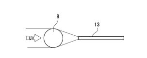
- the lens 8 capable of condensing the ultraviolet light is a ball lens, and condenses the ultraviolet light transmitted through the beam splitter 12 on the end face of the optical fiber 13 (on which an antireflection film is formed), and also the measuring cell 3
- the ultraviolet light which is emitted from the optical fiber 13 and is returned through the optical fiber 13 is collimated toward the beam splitter 12. This collimated light is split into two beams by the beam splitter 12, one beam is transmitted through the beam splitter 12, and the other beam is reflected by the beam splitter 12 and directed to the photodetector 4.
- the ultraviolet light that has entered the optical module 6 from the multiplexing module 10 through the optical fiber 11 is collimated by another ball lens 14 and split into two beams by the beam splitter 12, and one beam is a beam splitter.
- the other beam passing through 12 is reflected by the beam splitter 12 toward the reference photodetector 15.
- the reference photodetector 15 can use the same photosensor as the photodetector 4.
- the detection signal detected by the reference photodetector 15 can be used for correcting the detection signal of the photodetector 4.
- the photodetector 4 and the reference photodetector 15 are directly attached to the casing 7 of the optical module 6, but can be connected via an optical fiber (not shown).
- the ultraviolet light of the absorption wavelength component of the light that is incident on the measuring cell 3 and then is reflected by the reflecting member 3f is present in the measured flow rate channel 3a in the measuring cell 3. It is absorbed by the fluid to be measured (gas, etc.). The magnitude of the absorption depends on the concentration of the fluid to be measured.
- the calculation unit 5 can measure the absorbance A ⁇ at the absorption wavelength by frequency-analyzing the detection signal from the photodetector 4, and further, the Lambert-Beer shown in the following formula (1). Based on the law, the gas concentration C can be calculated from the absorbance A ⁇ .
- I 0 is the intensity of incident light that enters the measurement cell
- I is the intensity of light that has passed through the gas in the measurement cell
- ⁇ is the molar extinction coefficient (m 2 /mol)
- L is The optical path length (m) of the measurement cell
- C are the concentrations (mol/m 3 ).
- the molar absorption coefficient ⁇ is a coefficient determined by the substance.
- the incident light intensity I 0 in the above formula (1) is measured when there is no light-absorbing gas in the measurement cell 3 (for example, when a purge gas that does not absorb ultraviolet light is full or when a vacuum is drawn).
- the light intensity detected by the photodetector 4 may be regarded as the incident light intensity I 0 .
- the light detected by the reference light detector 15 is not absorbed by the fluid to be measured.
- the calculation unit 5 can correct the detection signal of the photodetector 4 based on the following equation (2).
- I cor I cell ⁇ (I ref,0 /I ref ) (2)
- I cor is the corrected light intensity of the photodetector 4
- I ref,0 is the initial intensity of the light detected by the reference photodetector 15, and I cell is detected by the photodetector 4.
- the light intensity at the time of measurement I ref is the light intensity at the time of measurement detected by the reference light detector 15.
- adsorbent 9 accommodated in the casing 7 of the optical module 6 those that adsorb gas molecules in the casing 7 can be preferably used, and examples thereof include molecular sieve, zeolite, activated carbon, aluminum oxide, activated clay and silica. It may be one or more selected from the group consisting of algae earth, activated alumina, silica gel, and a porous coordination polymer (PCP).
- PCP porous coordination polymer
- the adsorbent 9 can be used in various forms such as powder, granules or pellets. Various methods can be used for fixing the adsorbent 9 in the casing 7. For example, a container (not shown) containing the adsorbent can be fixed to the casing 7, and the container is , A lid with a vent can be provided.
- the casing 7, the lens 8 and other components that make up the optical module 6 have a portion fixed by adhesion, but the adhesive contains an organic solvent, and the organic solvent volatilizes to become gas, It may adhere to the end surface of the optical fiber 13 inside the casing 7.
- the end surface of the optical fiber 13 has a diameter of 200 ⁇ m, and a current of 30 mA is applied to the light emitting diodes of the light sources 2a and 2b for 40 hours in the burn-in process.
- the organic compound may be decomposed and carbonized and attached.
- the adsorbent 9 that adsorbs gas molecules is housed in the casing 7, even if the organic compound gas floats in the casing 7 due to volatilization of the organic solvent in the adhesive, it is adsorbed. This makes it possible to prevent the carbide from adhering to the end surface of the optical fiber 13 inside the casing 7.
- the configuration in which the ultraviolet light enters and exits in the single window portion of the measurement cell has been illustrated, but it is also possible to separately provide an entrance window into which the ultraviolet light enters and an exit window to exit.
- the entrance window and the exit window may be arranged adjacent to each other, or the exit window may be provided instead of the reflecting member and the entrance window and the exit window may be arranged to face each other.
- the optical module that accommodates the adsorbent is not limited to the demultiplexing module as in the above embodiment, and may be a lens, a prism, a light emitting element, a light receiving element, an optical fiber connector, or the like depending on the optical system used in the concentration measuring device. It is possible to employ an optical module that appropriately incorporates optical components in a casing and performs a light beam operation such as multiplexing, demultiplexing, or focusing.
- the light source that emits ultraviolet light can be a single light source with a single wavelength, or can combine three or more different wavelengths of ultraviolet light.
- the device for guiding the incident light and the emitted light by one optical fiber 13 has been described, but it is also preferable to use the two-core type concentration measuring device. ..
- Such a two-core type concentration measuring device is described in, for example, Patent Document 4 (FIG. 8 and the like).
- the measuring cell 3 and the optical module 6A are connected by the incident optical fiber 13a, and the measuring cell 3 and the photodetector 4 are connected by the emitting optical fiber 13b. It is connected.
- the lights from the light sources 2a and 2b are combined by the optical module 6A (combiner in this example), guided by the incidence fiber 13a, and incident on the measurement cell 3 through the window 3b.
- the emitted light (measuring light) reflected by the reflecting member 3f and emitted from the measuring cell 3 is guided by the emitting optical fiber 13b and received by the photodetector 4.
- the adsorbent 9 is housed in the casing 7A of the optical module 6A. Further, as shown in FIG. 3, the generation of stray light can be reduced also by arranging the window surface normal direction of the window portion 3b with an inclination of, for example, about 1 to 5° from the optical axis direction of the collimating lens 3g.
- the collimator lens 3g can make incident light incident on the measurement cell 3 as parallel light.
- the gas inlet and the gas outlet of the measuring cell 3 may be provided on the same side surface of the measuring cell 3, unlike the embodiment shown in FIG.
- the reflection type concentration measuring device using the reflecting member has been described above, the incident light is made incident from one end side of the measuring cell and the measuring light is taken out from the other end side of the measuring cell without using the reflecting member. It is also possible to use a transmission type concentration measuring device configured as described above.
Landscapes
- Physics & Mathematics (AREA)
- Spectroscopy & Molecular Physics (AREA)
- Health & Medical Sciences (AREA)
- Life Sciences & Earth Sciences (AREA)
- Chemical & Material Sciences (AREA)
- Analytical Chemistry (AREA)
- Biochemistry (AREA)
- General Health & Medical Sciences (AREA)
- General Physics & Mathematics (AREA)
- Immunology (AREA)
- Pathology (AREA)
- Investigating Or Analysing Materials By Optical Means (AREA)
Abstract
バーンイン後に光検出器で検出する光の強度が極端に低くなる出力低下現象を抑制し得る濃度測定装置を提供する。紫外光を発生させる光源2a,2bと、紫外光が入出射する被測定流体用流路3aを備える測定セル3と、測定セル3から出射した紫外光を検出する光検出器4と、光検出器4の検出信号に基づいて被測定流体の濃度を演算する演算部5と、紫外線の伝送経路に介在された光モジュール6と、を備え、光モジュール6は、ケーシング7と、ケーシング7内に収容されて紫外光を集光可能なレンズ8と、ケーシング7内に収容された吸着剤9とを備える。
Description
本発明は、濃度測定装置に関し、特に、被測定流体が導入された測定セルに光を入射させ、前記測定セルから出射した被測定流体通過光を検出することによって被測定流体の濃度を測定する濃度測定装置に関する。
従来、この種の濃度測定装置では、被測定流体が供給される測定セルの光入射窓に、光源から所定波長の光を入射させ、前記測定セル内を通過した通過光を受光素子で受光することにより吸光度を測定し、前記吸光度からランベルト・ベールの法則に従って前記被測定流体の濃度を求めることができる(特許文献1~4等)。
しかしながら、上記従来の濃度測定装置において、濃度測定のために光検出器で検出する光の強度が極端に低い現象(出力低下現象)を発生する場合があった。
そこで本発明は、斯かる出力低下現象を抑制し得る濃度測定装置を提供することを主たる目的とする。
上記目的を達成するため、発明者等は、鋭意研究に結果、光検出器と測定セルとの間に設けた分波器内において、前記分波器に接続された光ファイバの端面に迷光を防ぐために設けた反射防止膜(ARコート:Anti Reflection Coating)の表面に、黒いシミのようなものが付着しており、このシミが前記出力低下現象の原因であることを見出した。そして、そのシミは、分析の結果、炭素であることも判明した。更に調査を進めると、前記出力低下現象がバーンイン工程後に生じることが分かった。このバーンイン工程とは、光源(紫外線発光ダイオード)に規格範囲内の最大電流値を与え、光量を安定化させるために製品出荷前に行われる工程である。
反射防止膜は無機材料(タンタル等)で形成されていることから、反射防止膜の付着物の炭素は、有機物が紫外光によって分解されたものと考えられる。濃度測定装置で使用される紫外光は強いエネルギーを持ち、ビームスプリッタを透過した紫外光を細い光ファイバ端面に集光するために集光用のレンズを用いることに依りいっそうエネルギー密度が高くなり、その結果、僅かな有機物であっても分解して光ファイバの入射側端面に付着させたと考えられる。光モジュール内に存在する有機物は、レンズの固定等に用いられる接着剤や溶剤から蒸発等により放出されたものと考えられる。
そこで、本発明の一態様に係る濃度測定装置は、紫外光を発生させる光源と、前記紫外光が入出射する被測定流体用流路を備える測定セルと、前記測定セルから出射した紫外光を検出する光検出器と、前記光検出器の検出信号に基づいて被測定流体の濃度を演算する演算部と、前記紫外線の伝送経路に介在された光モジュールと、を備え、前記光モジュールは、ケーシングと、前記ケーシング内に収容されて前記紫外光を集光可能なレンズと、前記ケーシング内に収容された吸着剤とを備える。
前記吸着剤は、モレキュラーシーブ、ゼオライト、活性炭、酸化アルミニウム、活性白土、ケイ藻土、活性アルミナ、シリカゲル、及び、多孔性配位高分子からなる群から選ばれる一種又は二種以上とすることができる。
本発明によれば、ケーシング内に収容された吸着剤が光モジュール内に放出されている有機物を吸収することにより、上記出力低下現象を低減することができる。
本発明に係る濃度測定装置の実施形態について、以下に図1~図3を参照して説明する。なお、全図及び全実施形態を通じて、同一又は類似の構成要素には同符号を付している。
濃度測定装置1は、紫外光を発生させる光源2a、2bと、紫外光が入射・出射する被測定流体用流路3aを備える測定セル3と、測定セル3から出射した紫外光(出射光)を検出する光検出器4と、光検出器4の検出信号に基づいて被測定流体の濃度を演算する演算部5と、紫外線の伝送経路に介在された光モジュール6と、を備える。光モジュール6は、ケーシング7と、ケーシング7内に収容されて紫外光を集光可能なレンズ8と、ケーシング7内に収容された吸着剤9とを備える。
光源2a、2bは、其々が異なる波長の紫外光を発する発光ダイオードである。図示例では、合波モジュール10によって異なる2つの波長(365nm、310nm)の紫外光が合波されて波長分割多重方式により光ファイバ11を通じて光モジュール6に伝送されている。周波数解析(例えば、高速フーリエ変換やウェーブレット変換)を行うことによって、光検出器4が検出した検出信号から、各波長成分に対応した光の強度を測定することができる。図1中、符号10aはハーフミラー、符号10bは集光用のレンズ(ボールレンズ)を其々示している。
図1に示された測定セル3は、被測定流体用流路3aの一端側に透光性の窓部3bを備え、窓部3bに対向して被測定流体用流路3aの他端側に別の窓部3cを介して反射部材3fが設けられている。被測定流体用流路3aには、被測定流体の流入口3dと流出口3eとが離間して設けられている。窓部3bから測定セル3内に入射した紫外光は、被測定流体用流路3aを伝搬し、反射部材3fで反射して再び窓部3bから出射する。窓部3b、3cは、例えばサファイアガラス又は石英ガラスによって形成することができる。反射部材3fは、例えば、サファイアガラスに、アルミニウム蒸着膜、反射ミラー、或いは、誘電電体多層膜を設けたものを用いることができる。
光検出器4は、フォトダイオードを用いることができるが、これに限られず、例えばフォトトランジスタなどを用いてもよい。演算部5は、例えば、回路基板上に設けられたCPUやメモリなどを用いて構成されていてよく、入力信号に基づいて所定の演算を実行するコンピュータプログラムを含み、ハードウェアとソフトウェアとの組み合わせによって実現され得る。
光モジュール6は、図示例では、ビームスプリッタ12を備える光分波モジュールであり、光源2a、2bが接続された合波モジュール10と測定セル3との間に介在され、合波モジュール10と測定セル3とに光コネクタを介して光ファイバ11,13で接続されている。紫外光を集光可能なレンズ8は、ボールレンズであり、ビームスプリッタ12を透過した紫外光を光ファイバ13の端面(反射防止膜が形成されている。)に集光させるとともに、測定セル3から出射し光ファイバ13を伝送されて戻ってきた紫外光をビームスプリッタ12に向けて平行光にする。この平行光は、ビームスプリッタ12で2つのビームに分けられ、一方のビームはビームスプリッタ12を透過し、他方のビームはビームスプリッタ12で反射させられて光検出器4に向けられる。
また、光ファイバ11を通じて合波モジュール10から光モジュール6に入射した紫外光は、別のボールレンズ14で平行光とされて、ビームスプリッタ12で2つのビームに分けられ、一方のビームはビームスプリッタ12を透過し、他方のビームはビームスプリッタ12で参照光検出器15に向けて反射させられる。参照光検出器15は、光検出器4と同様の光センサーを用いることができる。参照光検出器15で検出された検出信号は、光検出器4の検出信号の補正に用いられ得る。
図示例において、光検出器4及び参照光検出器15は、光モジュール6のケーシング7に直接取り付けられているが、光ファイバ(図示せず。)を介して接続することもできる。
濃度測定装置1において、測定セル3に入射され、その後、反射部材3fによって反射された光のうちの吸収波長成分の紫外光が、測定セル3内の被測定流量用流路3a内に存在する被測定流体(ガス等)により吸収される。吸収の大きさは被測定流体の濃度に依存する。そして、演算部5は、光検出器4からの検出信号を周波数解析することによって、当該吸収波長での吸光度Aλを測定することができ、さらに、以下の式(1)に示すランベルト・ベールの法則に基づいて、吸光度Aλからガス濃度Cを算出することができる。
Aλ=-log10(I/I0)=αLC ・・・(1)
上記の式(1)において、I0は測定セルに入射する入射光の強度、Iは測定セル内のガス中を通過した光の強度、αはモル吸光係数(m2/mol)、Lは測定セルの光路長(m)、Cは濃度(mol/m3)である。モル吸光係数αは物質によって決まる係数である。
上記の式(1)において、I0は測定セルに入射する入射光の強度、Iは測定セル内のガス中を通過した光の強度、αはモル吸光係数(m2/mol)、Lは測定セルの光路長(m)、Cは濃度(mol/m3)である。モル吸光係数αは物質によって決まる係数である。
なお、上記式(1)における入射光強度I0については、測定セル3内に吸光性のガスが存在しないとき(例えば、紫外光を吸収しないパージガスが充満しているときや、真空に引かれているとき)に光検出器4によって検出された光の強度を入射光強度I0と見なしてよい。
参照光検出器15で検出された光は、被測定流体による吸収を受けていない。参照光検出器15で検出された光の初期強度(Iref,0)から経時後の測定時における参照光検出器15で検出された光強度(Iref)への変化率(Iref/Iref,0)は、温度を代表とする周囲環境による変化、光学素子の経年劣化、或いは、発光素子の駆動安定迄の発光強度変化等によるものと考えられる。従って、前記変化率(Iref/Iref,0)の逆数(Iref,0/Iref)を、光検出器4の測定時の光強度(Icell)に乗算することにより、光検出器4の検出信号を補正することができる。
従って、演算部5は、下記式(2)に基づいて光検出器4の検出信号を補正することができる。
Icor=Icell×(Iref,0/Iref) ・・・ (2)
上式(2)において、Icorは補正された光検出器4の光強度、Iref,0は参照光検出器15で検出された光の初期強度、Icellは光検出器4で検出された測定時の光強度、Irefは参照光検出器15で検出された測定時の光強度である。
Icor=Icell×(Iref,0/Iref) ・・・ (2)
上式(2)において、Icorは補正された光検出器4の光強度、Iref,0は参照光検出器15で検出された光の初期強度、Icellは光検出器4で検出された測定時の光強度、Irefは参照光検出器15で検出された測定時の光強度である。
光モジュール6のケーシング7内に収容された吸着剤9は、ケーシング7内の気体分子を吸着するものを好適に用いることができ、例えば、モレキュラーシーブ、ゼオライト、活性炭、酸化アルミニウム、活性白土、ケイ藻土、活性アルミナ、シリカゲル、及び、多孔性配位高分子(PCP)からなる群から選ばれる一種又は二種以上とすることができる。
吸着剤9は、粉末状、粒状、又はペレット状等の種々形態のものを用いることができる。吸着剤9のケーシング7内への固定方法は、種々の方法を用いることができるが、例えば、吸着剤を収容した容器(図示せず。)をケーシング7に固定することができ、前記容器は、通気孔を備える蓋を備えることができる。
光モジュール6を構成しているケーシング7、レンズ8、その他の構成部品は、接着により固定される箇所があるが、接着剤には有機溶剤を含んでおり、有機溶剤が揮発してガスとなり、ケーシング7内において光ファイバ13の端面に付着する可能性がある。ある実施例では、光ファイバ13の端面の直径は200μmであり、バーンイン工程において光源2a、2bの発光ダイオードに30mAの電流が40時間流される。有機化合物が付着した光ファイバ13の端面にこのような強力な紫外光がボールレンズ8で集光されて照射(図2参照)されると、有機化合物が分解して炭化して付着し得る。
ケーシング7内にガス分子を吸着する吸着剤9を収容しておけば、前記接着剤中の有機溶媒が揮発する等してケーシング7内に有機化合物のガスが浮遊してもそれを吸着することにより、ケーシング7内における光ファイバ13の端面への炭化物の付着を抑止することができる。
本発明は、上記実施形態に限定解釈されるものではなく、本発明の趣旨を逸脱しない範囲において種々の変更が可能である。
例えば、上記実施形態では、測定セルの単一の窓部において紫外光が入射及び出射する構成を例示したが、紫外光が入射する入射窓と出射する出射窓を別個に設けることもでき、その場合に、入射窓と出射窓を隣り合って配置することもできるし、或いは、反射部材に代えて出射窓を設けて入射窓と出射窓を対向して配置することもできる。
また、吸着剤を収容する光モジュールは、上記実施形態のような分波モジュールに限らず、濃度測定装置に用いる光学系に応じて、レンズ、プリズム、発光素子、受光素子、光ファイバコネクタ等の光学部品をケーシングに適宜組み込み、合波、分波、或いは集光等の光ビーム操作をなす光モジュールを採用することができる。
また、紫外光を発する光源は、単一波長の単一の光源とすることもできるし、3以上の異なる波長の紫外光を合波することもできる。
また、上記には図1に示したように、入射光と出射光とを1本の光ファイバ13で導光する装置を説明したが、二芯式の濃度測定装置を用いることも好適である。このような二芯式の濃度測定装置は、例えば、特許文献4(図8等)に記載されている。
図3に示すように、二芯式の濃度測定装置1Aでは、測定セル3と光モジュール6Aとが入射光ファイバ13aとによって接続され、測定セル3と光検出器4とが出射光ファイバ13bによって接続されている。光源2a、2bからの光は、光モジュール6A(この例では合波器)で合波されて入射用ファイバ13aによって導光され、窓部3bを介して測定セル3に入射される。また、反射部材3fによって反射され測定セル3から出射した出射光(測定光)は、出射光ファイバ13bによって導光され、光検出器4で受光される。このように入射光と出射光とを別経路で導光することによって、迷光の影響を低減し得る。光モジュール6Aのケーシング7A内に吸着剤9が収容されている。また、図3に示すように、窓部3bの窓面法線方向をコリメートレンズ3gの光軸方向から例えば1~5°程度傾けて配置することによっても迷光の発生を低減し得る。コリメートレンズ3gは、入射光を測定セル3に平行光として入射させることができる。測定セル3のガス流入口とガス流出口とは、図1に示した態様とは異なり、測定セル3の同じ側面に設けられていてもよい。
また、上記には反射部材を用いる反射型の濃度測定装置を説明したが、反射部材を用いることなく、測定セルの一端側から入射光を入射させ、測定セルの他端側から測定光を取り出すように構成された透過型の濃度測定装置を用いることもできる。
1、1A 濃度測定装置
2a、2b 光源
3 測定セル
4 光検出器
5 演算部
6、6A 光モジュール
7、7A ケーシング
8 レンズ
9 吸着剤
10b レンズ
2a、2b 光源
3 測定セル
4 光検出器
5 演算部
6、6A 光モジュール
7、7A ケーシング
8 レンズ
9 吸着剤
10b レンズ
Claims (2)
- 紫外光を発生させる光源と、前記紫外光が入出射する被測定流体用流路を備える測定セルと、前記測定セルから出射した紫外光を検出する光検出器と、前記光検出器の検出信号に基づいて被測定流体の濃度を演算する演算部と、前記紫外線の伝送経路に介在された光モジュールと、を備え、
前記光モジュールは、ケーシングと、前記ケーシング内に収容されて前記紫外光を集光可能なレンズと、前記ケーシング内に収容された吸着剤とを備える、濃度測定装置。 - 前記吸着剤は、モレキュラーシーブ、ゼオライト、活性炭、酸化アルミニウム、活性白土,ケイ藻土,活性アルミナ,シリカゲル、及び、多孔性配位高分子からなる群から選ばれる一種又は二種以上である、請求項1に記載の濃度測定装置。
Applications Claiming Priority (2)
| Application Number | Priority Date | Filing Date | Title |
|---|---|---|---|
| JP2018-248659 | 2018-12-28 | ||
| JP2018248659 | 2018-12-28 |
Publications (1)
| Publication Number | Publication Date |
|---|---|
| WO2020137629A1 true WO2020137629A1 (ja) | 2020-07-02 |
Family
ID=71129747
Family Applications (1)
| Application Number | Title | Priority Date | Filing Date |
|---|---|---|---|
| PCT/JP2019/048960 Ceased WO2020137629A1 (ja) | 2018-12-28 | 2019-12-13 | 濃度測定装置 |
Country Status (2)
| Country | Link |
|---|---|
| TW (1) | TW202030473A (ja) |
| WO (1) | WO2020137629A1 (ja) |
Cited By (1)
| Publication number | Priority date | Publication date | Assignee | Title |
|---|---|---|---|---|
| JP2021028614A (ja) * | 2019-08-09 | 2021-02-25 | 東亜ディーケーケー株式会社 | 光学装置 |
Citations (4)
| Publication number | Priority date | Publication date | Assignee | Title |
|---|---|---|---|---|
| US6002133A (en) * | 1997-08-19 | 1999-12-14 | Datex-Ohmeda, Inc. | Serviceable absorbent for gas spectrometer interior |
| JP2003214958A (ja) * | 2002-01-21 | 2003-07-30 | Gigaphoton Inc | 波長検出装置、レーザ装置及び波長検出方法 |
| JP2008175649A (ja) * | 2007-01-17 | 2008-07-31 | Shimadzu Corp | 分光光度計 |
| WO2017029791A1 (ja) * | 2015-08-18 | 2017-02-23 | 国立大学法人徳島大学 | 濃度測定装置 |
-
2019
- 2019-12-13 WO PCT/JP2019/048960 patent/WO2020137629A1/ja not_active Ceased
- 2019-12-24 TW TW108147321A patent/TW202030473A/zh unknown
Patent Citations (4)
| Publication number | Priority date | Publication date | Assignee | Title |
|---|---|---|---|---|
| US6002133A (en) * | 1997-08-19 | 1999-12-14 | Datex-Ohmeda, Inc. | Serviceable absorbent for gas spectrometer interior |
| JP2003214958A (ja) * | 2002-01-21 | 2003-07-30 | Gigaphoton Inc | 波長検出装置、レーザ装置及び波長検出方法 |
| JP2008175649A (ja) * | 2007-01-17 | 2008-07-31 | Shimadzu Corp | 分光光度計 |
| WO2017029791A1 (ja) * | 2015-08-18 | 2017-02-23 | 国立大学法人徳島大学 | 濃度測定装置 |
Cited By (1)
| Publication number | Priority date | Publication date | Assignee | Title |
|---|---|---|---|---|
| JP2021028614A (ja) * | 2019-08-09 | 2021-02-25 | 東亜ディーケーケー株式会社 | 光学装置 |
Also Published As
| Publication number | Publication date |
|---|---|
| TW202030473A (zh) | 2020-08-16 |
Similar Documents
| Publication | Publication Date | Title |
|---|---|---|
| JP6248098B2 (ja) | 溶液中の物質の吸光度を測定する方法並びに装置 | |
| KR102122840B1 (ko) | 분광 분석 방법 및 분광 분석 장치 | |
| US10132787B2 (en) | Device for optically determining the concentration of alcohol and carbohydrates in a liquid sample | |
| KR102733863B1 (ko) | 농도 측정 방법 및 농도 측정 장치 | |
| WO2013105450A1 (ja) | ガスセンサ | |
| US11662307B2 (en) | Optical concentration measuring device, module for optical concentration measuring device and optical concentration measuring method | |
| KR102535963B1 (ko) | 농도 측정 장치 | |
| WO2013147038A1 (ja) | 物質特性測定装置 | |
| US20160033783A1 (en) | Optical system for generating beam of reference light and method for splitting beam of light to generate beam of reference light | |
| KR102561924B1 (ko) | 농도 측정 장치 | |
| WO2008145115A3 (de) | Vorrichtung und verfahren zur bestimmung der permeationsrate mindestens eines permeaten durch ein eine diffusionssperre bildendes element | |
| JP6062837B2 (ja) | 液体クロマトグラフ用検出器 | |
| JP2016161455A (ja) | 液体クロマトグラフ用遠紫外吸光度検出装置 | |
| TWI751684B (zh) | 濃度測定裝置 | |
| JPWO2020066769A5 (ja) | ||
| KR20210027428A (ko) | 농도 측정 방법 | |
| WO2020137629A1 (ja) | 濃度測定装置 | |
| US9442064B1 (en) | Photometer with LED light source | |
| US11940326B2 (en) | Spectroscopic analysis device, optical system, and method | |
| RU2012142133A (ru) | Светоизлучающий модуль | |
| KR102555556B1 (ko) | 흡광도계 | |
| JP4910588B2 (ja) | 水質測定装置 | |
| JP2016180609A (ja) | 紫外光吸収による検出装置 | |
| CN113804640B (zh) | 一种气体浓度测量用的光学系统 | |
| US20250208038A1 (en) | Measuring arrangements and methods for the detection of trace gases in a sample gas |
Legal Events
| Date | Code | Title | Description |
|---|---|---|---|
| 121 | Ep: the epo has been informed by wipo that ep was designated in this application |
Ref document number: 19905461 Country of ref document: EP Kind code of ref document: A1 |
|
| NENP | Non-entry into the national phase |
Ref country code: DE |
|
| 122 | Ep: pct application non-entry in european phase |
Ref document number: 19905461 Country of ref document: EP Kind code of ref document: A1 |
|
| NENP | Non-entry into the national phase |
Ref country code: JP |