WO2020137294A1 - ロータ、およびモータ - Google Patents
ロータ、およびモータ Download PDFInfo
- Publication number
- WO2020137294A1 WO2020137294A1 PCT/JP2019/045895 JP2019045895W WO2020137294A1 WO 2020137294 A1 WO2020137294 A1 WO 2020137294A1 JP 2019045895 W JP2019045895 W JP 2019045895W WO 2020137294 A1 WO2020137294 A1 WO 2020137294A1
- Authority
- WO
- WIPO (PCT)
- Prior art keywords
- rotor
- connecting portion
- inner core
- core portion
- circumferential direction
- Prior art date
- Legal status (The legal status is an assumption and is not a legal conclusion. Google has not performed a legal analysis and makes no representation as to the accuracy of the status listed.)
- Ceased
Links
Images



Classifications
-
- H—ELECTRICITY
- H02—GENERATION; CONVERSION OR DISTRIBUTION OF ELECTRIC POWER
- H02K—DYNAMO-ELECTRIC MACHINES
- H02K1/00—Details of the magnetic circuit
- H02K1/06—Details of the magnetic circuit characterised by the shape, form or construction
- H02K1/22—Rotating parts of the magnetic circuit
-
- H—ELECTRICITY
- H02—GENERATION; CONVERSION OR DISTRIBUTION OF ELECTRIC POWER
- H02K—DYNAMO-ELECTRIC MACHINES
- H02K1/00—Details of the magnetic circuit
- H02K1/06—Details of the magnetic circuit characterised by the shape, form or construction
- H02K1/22—Rotating parts of the magnetic circuit
- H02K1/27—Rotor cores with permanent magnets
-
- H—ELECTRICITY
- H02—GENERATION; CONVERSION OR DISTRIBUTION OF ELECTRIC POWER
- H02K—DYNAMO-ELECTRIC MACHINES
- H02K21/00—Synchronous motors having permanent magnets; Synchronous generators having permanent magnets
- H02K21/12—Synchronous motors having permanent magnets; Synchronous generators having permanent magnets with stationary armatures and rotating magnets
- H02K21/14—Synchronous motors having permanent magnets; Synchronous generators having permanent magnets with stationary armatures and rotating magnets with magnets rotating within the armatures
- H02K21/16—Synchronous motors having permanent magnets; Synchronous generators having permanent magnets with stationary armatures and rotating magnets with magnets rotating within the armatures having annular armature cores with salient poles
Definitions
- the present invention relates to a rotor and a motor.
- Patent Document 1 describes a configuration in which a bridge portion is inclined with respect to the radial direction and extends linearly.
- the angle of the bridge portion connected to the outer peripheral portion is likely to be relatively large in the tangential direction of the outer peripheral portion. Therefore, in some cases, the strength of the connecting portion of the bridge portion with the outer peripheral portion cannot be sufficiently obtained and the strength of the rotor steel sheet cannot be sufficiently obtained with respect to the circumferential shearing stress generated by the rotating torque.
- the present invention has an object to provide a rotor having a structure capable of suitably improving the strength of a rotor core having a plurality of connecting portions that connect an inner core portion and an outer core portion, and a motor. To do.
- One aspect of the rotor of the present invention includes a rotor core that rotates about a central axis, and a rotor magnet fixed to the rotor core.
- the rotor core has an annular inner core portion along the circumferential direction, an outer core portion that is positioned radially outside the inner core portion, and has the rotor magnet fixed, the inner core portion and the outer core portion.
- a plurality of connecting portions that connect the inner core portion and the outer core portion with each other.
- the plurality of connecting portions include a curved first connecting portion that curves toward one side in the circumferential direction from the inner core portion toward the outer core portion when viewed in the axial direction, and the curved first connecting portion when viewed in the axial direction.
- a curved second connecting portion that curves toward the other side in the circumferential direction from the inner core portion toward the outer core portion.
- the first connecting portion and the second connecting portion have portions having the same axial position.
- a rotor and a motor in a rotor and a motor, it is possible to preferably improve the strength of a rotor core having a plurality of connecting portions that connect the inner core portion and the outer core portion.
- FIG. 1 is a cross-sectional view showing a rotary blade device of this embodiment.
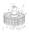
- FIG. 2 is a perspective view showing the rotor of this embodiment.
- FIG. 3 is a view of the rotor of this embodiment as viewed from above.
- FIG. 4 is a view of a part of the rotor of the present embodiment as viewed from above.
- the Z-axis direction shown in each drawing is a vertical direction in which the positive side is "upper side” and the negative side is “lower side”.
- a central axis J shown in each drawing is an imaginary line that is parallel to the Z-axis direction and extends in the vertical direction.
- the axial direction of the central axis J that is, the direction parallel to the vertical direction is simply referred to as “axial direction”
- the radial direction around the central axis J is simply referred to as “radial direction”
- the central axis J The circumferential direction centered at is simply referred to as the “circumferential direction”.
- an arrow ⁇ indicating the circumferential direction is shown.
- the side traveling clockwise in the circumferential direction that is, the side traveling in the direction of the arrow ⁇ when viewed from the upper side to the lower side is referred to as “one side in the circumferential direction”.
- the side that moves counterclockwise in the circumferential direction that is, the side that moves in the direction opposite to the direction of the arrow ⁇ when viewed from the upper side to the lower side is referred to as “the other side in the circumferential direction”.
- the up-down direction, the upper side, and the lower side are merely names for explaining the positional relationship between the respective parts, and the actual positional relationship is a positional relationship other than the positional relationship indicated by these names. May be.
- the motor 10 of the present embodiment is mounted on the rotary wing device 1.
- the rotary wing device 1 is mounted on, for example, an unmanned aerial vehicle.
- the rotary wing device 1 includes a motor 10 and a propeller 2.
- the housing 40 accommodates the rotor 20, the stator 30, the sensor assembly 50, the bus bar assembly 60, the first bearing 71, and the second bearing 72 therein.
- a plurality of fins 45 arranged along the circumferential direction are provided on the outer peripheral surface of the housing 40.
- the stator 30 is located radially outside the rotor 20.
- the stator 30 has a stator core 31, an insulator 32, and a plurality of coils 33.
- the plurality of coils 33 are attached to the stator core 31 via the insulator 32.
- the sensor assembly 50 is located below the rotor 20.
- the sensor assembly 50 includes a sensor holder 51, a rotation sensor 52, and a circuit board 53.
- the rotation sensor 52 is held by the sensor holder 51.
- the rotation sensor 52 is a magnetic sensor that detects a magnetic field of the rotor magnet 23 described later.
- the rotation sensor 52 is, for example, a Hall element such as a Hall IC.
- the rotation sensor 52 detects the rotation of the rotor 20 by detecting the magnetic field of the rotor magnet 23. Although illustration is omitted, a plurality of rotation sensors 52 are provided along the circumferential direction.
- the rotation sensor 52 may be a magnetoresistive element.
- the circuit board 53 is fixed to the sensor holder 51.
- the terminals of the rotation sensor 52 are electrically connected to the circuit board 53.
- the bus bar assembly 60 is located below the stator 30.
- the bus bar assembly 60 is located radially outside the sensor assembly 50.
- the busbar assembly 60 has a busbar holder 61 and a busbar 62.
- the busbar holder 61 holds the busbar 62.
- the bus bar 62 is electrically connected to the coil 33.
- the rotor 20 includes a shaft 21, a rotor core 22, a rotor magnet 23, and a rotor cover 24.
- the rotor cover 24 is not shown in FIG.
- the shaft 21 is arranged along the central axis J.
- the shaft 21 has a cylindrical shape that extends in the axial direction around the central axis J.
- the upper end portion of the shaft 21 projects above the housing 40.
- the propeller mounting portion 80 is fixed to the upper end of the shaft 21.
- the rotor core 22 rotates with the shaft 21 about the central axis J.
- the rotor core 22 is fixed to the outer peripheral surface of the shaft 21.
- the rotor core 22 has an annular shape.
- the rotor core 22 has an annular shape centered on the central axis J.
- the rotor core 22 is configured, for example, by stacking electromagnetic steel plates in the axial direction.
- the rotor core 22 has an inner core portion 22a, an outer core portion 22b, a plurality of connecting portions 22c, and a plurality of supporting portions 22d.
- the inner core portion 22a has an annular shape along the circumferential direction.
- the inner core portion 22a has an annular shape centered on the central axis J.
- the inner core portion 22a is fixed to the outer peripheral surface of the shaft 21.
- the outer core portion 22b is located radially outside the inner core portion 22a.
- the outer core portion 22b has an annular shape along the circumferential direction. More specifically, the outer core portion 22b has an annular shape centered on the central axis J. As shown in FIGS. 1 and 2, the outer core portion 22b projects more axially than the inner core portion 22a.
- the rotor magnet 23 is fixed to the outer core portion 22b.
- the plurality of connecting portions 22c are located between the inner core portion 22a and the outer core portion 22b in the radial direction.
- the plurality of connecting portions 22c connect the inner core portion 22a and the outer core portion 22b.
- the plurality of connecting portions 22c include a first connecting portion 27a and a second connecting portion 27b.
- the first connecting portion 27a is a curved connecting portion 22c that curves toward one side in the circumferential direction as it goes from the inner core portion 22a to the outer core portion 22b when viewed along the axial direction.
- the second connecting portion 27b is a curved connecting portion 22c that curves toward the other side in the circumferential direction from the inner core portion 22a toward the outer core portion 22b when viewed along the axial direction.
- the strength against the circumferential shearing stress generated by the rotational torque can be improved in both the connecting portion of the connecting portion 22c with the inner core portion 22a and the connecting portion of the connecting portion 22c with the outer core portion 22b. .. Therefore, the strength of the rotor core 22 can be suitably improved. Therefore, it is possible to preferably suppress the deformation of the rotor core 22 when the rotor 20 rotates. Thereby, the responsiveness of the motor 10 can be improved.
- the second connecting portion 27b bends toward the other side in the circumferential direction as it goes from the inner core portion 22a to the outer core portion 22b when viewed along the axial direction. It is connected from one side in the circumferential direction.
- the second connecting portion 27b can easily receive the shear stress in the one circumferential direction, and has a particularly high strength against the shear stress in the one circumferential direction. Therefore, the second connecting portion 27b can particularly improve the strength of the rotor core 22 when the rotor 20 rotates to one side in the circumferential direction.
- first connecting portion 27a and the second connecting portion 27b having different curving circumferential directions are provided, when the rotor 20 rotates in any circumferential direction. Also, the strength of the rotor core 22 with respect to shear stress can be suitably improved.
- both the first connecting portion 27a and the second connecting portion 27b can be made of the electromagnetic steel sheets having the same shape. .. This makes it easy to manufacture the rotor core 22.
- the axial dimension of the first coupling portion 27a and the axial dimension of the second coupling portion 27b are the inner core. It is the same as the axial dimension of the portion 22a.
- the upper end of the connecting portion 22c is arranged at the same position as the upper end of the inner core portion 22a in the axial direction.
- the lower end of the connecting portion 22c is arranged at the same position as the lower end of the inner core portion 22a in the axial direction.
- the plurality of first connecting portions 27a are provided at intervals along the circumferential direction.
- the plurality of first connecting portions 27a are arranged at equal intervals over the entire circumference in the circumferential direction.
- a plurality of second connecting portions 27b are provided at intervals along the circumferential direction.
- the plurality of second connecting portions 27b are arranged at equal intervals along the circumference in the circumferential direction.
- the number of the first connecting portions 27a and the number of the second connecting portions 27b are the same.
- the first connecting portion 27a and the second connecting portion 27b are provided, for example, seven each. Thereby, for example, a total of 14 connecting portions 22c are provided.
- a plurality of connecting portion sets 28 are provided at equal intervals along the circumference in the circumferential direction. For example, seven sets of connecting portions 28 are provided.
- the number of sets of the connecting portion sets 28 is a number that is relatively prime to the number of poles and the number of slots of the motor 10. This can prevent the rotor core 22 from resonating.
- the motor 10 of this embodiment is, for example, a 20-pole, 18-slot motor.
- the intersecting portion 29 is a part of the first connecting portion 27a and also a part of the second connecting portion 27b.
- the first connecting portion 27 a includes the first inner portion 27 c located radially inside the intersecting portion 29 and the radially outer side than the intersecting portion 29.
- a first outer portion 27d located at.
- the first inner portion 27c is connected to the outer peripheral surface 22e of the inner core portion 22a.
- the radially inner end of the first inner portion 27c is the radially inner end of the first connecting portion 27a.
- the first outer portion 27d is connected to the inner peripheral surface 22f of the outer core portion 22b.
- the radially outer end of the first outer portion 27d is the radially outer end of the first connecting portion 27a.
- the second connecting portion 27b has a second inner portion 27e located radially inside the intersecting portion 29 and a second outer portion 27f located radially outside the intersecting portion 29.
- the second inner portion 27e is connected to the outer peripheral surface 22e of the inner core portion 22a.
- the radially inner end of the second inner portion 27e is the radially inner end of the second connecting portion 27b.
- the second outer portion 27f is connected to the inner peripheral surface 22f of the outer core portion 22b.
- the radially outer end of the second outer portion 27f is the radially outer end of the second connecting portion 27b.
- the intersection portion 29 is located at the central portion CA between the inner core portion 22a and the outer core portion 22b in the radial direction. Therefore, it is easy to make the length of the first inner portion 27c and the length of the first outer portion 27d about the same. As a result, it is possible to prevent one of the first inner portion 27c and the first outer portion 27d from becoming unevenly long. Therefore, both the first inner portion 27c and the first outer portion 27d can be made relatively short, and deformation of the first connecting portion 27a can be suppressed.
- both the second inner portion 27e and the second outer portion 27f can be made relatively short, and deformation of the second connecting portion 27b can be suppressed.
- the length of the first inner portion 27c is shorter than the length of the first outer portion 27d.
- the length of the second inner portion 27e is shorter than the length of the second outer portion 27f.
- the length of the first inner portion 27c and the length of the second inner portion 27e are the same, for example.
- the length of the first outer portion 27d and the length of the second outer portion 27f are the same, for example.
- the “length of the connecting portion” is the dimension of the connecting portion in the direction in which the connecting portion extends from the inner core portion to the outer core portion when viewed along the axial direction. That is, for example, the length of the first inner portion 27c is the dimension of the first inner portion 27c in the direction in which the first inner portion 27c extends when viewed along the axial direction.
- the central portion CA is an area corresponding to two portions toward the center when the radial distance between the inner core portion 22a and the outer core portion 22b is divided into four equal parts when viewed in the axial direction. .. More specifically, the central portion CA is a region between the bisector DL1 and the bisector DL2 in the radial direction.
- the bisector DL1 is a line that bisects a radial centerline CL between the inner core portion 22a and the outer core portion 22b and a tangent line TL1 on the outer peripheral surface 22e of the inner core portion 22a. ..
- the tangent line TL1 is a tangent line of the tangential line on the outer peripheral surface 22e of the inner core portion 22a at a position where the outer peripheral surface 22e intersects with a virtual line RL connecting the central axis J and the intersecting portion 29 when viewed along the axial direction.
- the bisector DL2 is a line that bisects the radial centerline CL and the tangent line TL2 on the inner peripheral surface 22f of the outer core portion 22b in the radial direction.
- the tangent line TL2 is a tangent line of the inner peripheral surface 22f of the outer core portion 22b at a position where the inner peripheral surface 22f intersects the virtual line RL when viewed along the axial direction.
- the tangent lines TL1 and TL2, the bisectors DL1 and DL2, and the radial center line CL are parallel to each other.
- the virtual line RL is orthogonal to the tangent lines TL1 and TL2, the bisectors DL1 and DL2, and the radial centerline CL.
- intersection is located in the center
- the intersection portion 29 is wholly located in the central portion CA, including the radial and circumferential centers 29a.
- the intersecting portion 29 is arranged inward of the center portion CA in the radial direction.
- the center 29a of the intersecting portion 29 is located radially inward of the radial centerline CL.
- the load due to shear stress is greater in the portion of the connecting portion 22c connected to the inner core portion 22a than in the portion of the connecting portion 22c connected to the outer core portion 22b. Therefore, the strength of the rotor core 22 as a whole can be improved more suitably by further improving the strength of the portion of the connecting portion 22c that is connected to the inner core portion 22a.
- the first inner portion 27c When viewed along the axial direction, the first inner portion 27c has a diameter orthogonal to the first end portion 27g on the other side in the circumferential direction in the portion of the outer peripheral surface 22e of the inner core portion 22a to which the first inner portion 27c is connected. It extends in a direction inclined to one side in the circumferential direction with respect to the direction RD1 and radially outward with respect to the tangential direction TD1 in contact with the first end portion 27g.
- the portion of the first inner portion 27c connected to the inner core portion 22a tends to be large. Therefore, a part of the first inner portion 27c is integrated with the inner core portion 22a, and the central portion of the rotor core 22 including the inner core portion 22a is likely to be radially enlarged. This may increase the mass of the rotor core 22.
- the first inner portion 27c extends in the direction inclined radially outward with respect to the tangential direction TD1. Therefore, it is possible to separate the first inner portion 27c from the inner core portion 22a to the outer side in the radial direction as compared with the case of extending along the tangential direction TD1. As a result, the portion of the first inner portion 27c connected to the inner core portion 22a can be made smaller. Therefore, it is possible to prevent the center portion of the rotor core 22 including the inner core portion 22a from increasing in size in the radial direction. Therefore, the mass of the rotor core 22 can be suppressed from increasing, and the weight of the motor 10 can be easily reduced.
- the second inner portion 27e When viewed along the axial direction, the second inner portion 27e has a diameter orthogonal to the second end portion 27h on the one circumferential side in the portion of the outer peripheral surface 22e of the inner core portion 22a to which the second inner portion 27e is connected. It extends in a direction inclined to the other side in the circumferential direction with respect to the direction RD2 and radially outward with respect to the tangential direction TD2 in contact with the second end portion 27h. Therefore, like the first inner portion 27c described above, the portion of the second inner portion 27e that is connected to the inner core portion 22a can be made smaller. Therefore, it is possible to further prevent the central portion of the rotor core 22 including the inner core portion 22a from increasing in size in the radial direction. Therefore, the mass of the rotor core 22 can be further suppressed, and the weight of the motor 10 can be reduced more easily.
- the width of the connecting portion 22c is increased at the radially inner end portion connected to the outer peripheral surface 22e and the radially outer end portion connected to the inner peripheral surface 22f. That is, the width of the first connecting portion 27a is set such that the radially inner end of the first inner portion 27c connected to the outer peripheral surface 22e and the radially outer end of the first outer portion 27d connected to the inner peripheral surface 22f. Larger at the edges.
- the width of the second connecting portion 27b is set such that the radially inner end of the second inner portion 27e connected to the outer peripheral surface 22e and the radially outer end of the second outer portion 27f connected to the inner peripheral surface 22f. Larger at the edges. Therefore, the connection between the connecting portion 22c and the inner core portion 22a and the connection between the connecting portion 22c and the outer core portion 22b can be made stronger. Thereby, the strength of the rotor core 22 can be improved more suitably.
- the “width of the connecting portion” is the dimension of the connecting portion in the direction orthogonal to both the axial direction and the extending direction of the connecting portion.
- the connecting portion set 28 is line-symmetric with respect to an imaginary line RL that connects the central axis J and the intersecting portion 29 when viewed along the axial direction. Therefore, regardless of the circumferential direction of the rotor 20, the strength of the rotor core 22 can be similarly secured, and the magnetic characteristics of the rotor 20 can be similarly obtained.
- the first connecting portion 27a and the second connecting portion 27b are line-symmetric with respect to the virtual line RL.
- the plurality of support portions 22d project radially outward from the outer core portion 22b.
- the plurality of support portions 22d are arranged at equal intervals over the circumference along the circumferential direction.
- Each of the plurality of rotor magnets 23 is arranged between a pair of circumferentially adjacent support portions 22d. Each rotor magnet 23 is supported by the pair of support portions 22d from both sides in the circumferential direction. As shown in FIGS. 2 and 3, the rotor magnet 23 has a substantially rectangular parallelepiped shape extending in the axial direction. The corners of the rotor magnet 23 are rounded. As shown in FIGS. 1 and 2, in the present embodiment, each of the plurality of rotor magnets 23 is configured by connecting two magnets in the axial direction.
- the upper end of the rotor magnet 23 is arranged at the same position as the upper end of the outer core portion 22b in the axial direction.
- the lower end of the rotor magnet 23 is located below the lower end of the outer core portion 22b.
- a portion of the rotor magnet 23 located below the outer core portion 22b is a protruding portion 23a that protrudes below the rotor core 22. That is, each of the plurality of rotor magnets 23 has a protrusion 23 a that protrudes below the rotor core 22.
- the rotation sensor 52 is located inside the protrusion 23a in the radial direction. Therefore, the rotation sensor 52 can easily suitably detect the magnetic field of the rotor magnet 23 having the N pole and the S pole as magnetic poles along the radial direction. Thereby, the rotation detection accuracy of the rotor 20 by the rotation sensor 52 can be improved. Further, it is not necessary to separately provide a magnet for detecting with the rotation sensor 52 in addition to the rotor magnet 23, and the number of parts of the motor 10 can be reduced.
- the rotation sensor 52 faces the lower end of the radially inner surface of the protrusion 23a in the radial direction with a gap in between.
- the protection member 25 is a member that is wound along the circumferential direction and presses the rotor magnet 23 from the outside in the radial direction.
- the protection member 25 contacts the radially outer surface of the plurality of rotor magnets 23.
- the protection member 25 is provided over almost the entire portion of the rotor magnet 23 that overlaps the rotor core 22 in the radial direction.
- the protection member 25 is a thread having elasticity.
- the protection member 25 is spirally wound over the radially outer surfaces of the plurality of rotor magnets 23.
- the protective member 25 is in a state of being stretched in the circumferential direction by being applied with tension.
- the protection member 25 is a non-magnetic material. Therefore, as compared with the case where the protection member 25 is a magnetic body, it is possible to suppress the generation of an eddy current in the protection member 25 due to the magnetic flux. As a result, the loss due to the eddy current can be reduced and the temperature rise of the rotor 20 due to the eddy current can be suppressed.
- the protection member 25 is made of resin, for example. Examples of the resin include polyamide resins.
- one end 25a of the protection member 25 has a ring shape.
- the one end 25a is formed into a ring shape by folding back the end of the thread-shaped protection member 25 and tying it to the protection member 25.
- One of the protrusions 23a of the rotor magnet 23 is passed through the one end 25a having a ring shape.
- the one end 25a is hooked in the circumferential direction on one of the protrusions 23a of the rotor magnet 23. That is, one of the protruding portions 23a of the rotor magnet 23 is a hooking portion 23b on which the one end 25a of the protection member 25 is hooked in the circumferential direction.
- the one end 25a is the end of the protective member 25 on the winding start side.
- a radially inner portion of the one end portion 25a contacts, for example, a lower surface of the outer core portion 22b.
- the one end portion 25a has a portion located in a gap between the hook portion 23b and the protruding portion 23a that is adjacent to the hook portion 23b in the circumferential direction.
- the resin portion 26 is a resin portion that covers the protection member 25 from the outside in the radial direction.
- the resin portion 26 has a cylindrical shape centered on the central axis J.
- the resin portion 26 is made of an adhesive and fixes the protection member 25 to the radially outer surface of the rotor magnet 23. That is, in this embodiment, the protection member 25 is fixed to the rotor magnet 23 with an adhesive. Examples of the adhesive include an epoxy adhesive.
- the other end of the protective member 25 is fixed to the radially outer surface of the rotor magnet 23 by the resin portion 26.
- the present invention is not limited to the above embodiment, and other configurations can be adopted.
- the first connecting portion is not particularly limited as long as it has a curved shape that curves toward one side in the circumferential direction from the inner core portion toward the outer core portion when viewed along the axial direction.
- the second connecting portion is not particularly limited as long as it is a curved shape that curves toward the other side in the circumferential direction from the inner core portion toward the outer core portion when viewed along the axial direction.
- the curvature of the curved first connecting portion and the curvature of the second connecting portion are not particularly limited as long as the inner core portion and the outer core portion can be connected.
- the curvature of the first connecting portion may be the same throughout.
- the first connecting portion may have portions having different curvatures.
- the curvature of the second connecting portion may be the same throughout.
- the second connecting portion may have portions having different curvatures.
- the intersecting portion where the first connecting portion and the second connecting portion intersect and are connected to each other may be arranged radially outward in the center portion between the inner core portion and the outer core portion in the radial direction, It may be arranged at the radial center of the central portion. The intersection may not be provided in the central portion.
- the first connecting portion and the second connecting portion may not have an intersecting portion that intersects and is connected.
- the connecting portions included in the connecting portion sets that are adjacent to each other in the circumferential direction may intersect and be connected to each other.
- the connecting portion set may be non-axisymmetric with respect to the virtual line RL.
- the first connecting portion and the second connecting portion may be axisymmetric with respect to the virtual line RL.
- the first inner portion of the first connecting portion may extend along the tangential direction TD1.
- the second inner portion of the second connecting portion may extend along the tangential direction TD2.
- the first connecting portion and the second connecting portion may have portions having different axial positions as long as they have portions having the same axial position.
- the plurality of first connecting portions, which are arranged at intervals along the circumferential direction may not be arranged at equal intervals but may be arranged at unequal intervals.
- the plurality of second connecting portions which are arranged at intervals along the circumferential direction, may not be arranged at equal intervals, but may be arranged at unequal intervals.
- the number of the first connecting portions and the number of the second connecting portions are not particularly limited as long as they are each one or more.
- the number of first connecting portions and the number of second connecting portions may be different from each other.
- the axial dimension of the first connecting portion and the axial dimension of the second connecting portion may be different from each other.
- the rotor core does not have to be made of an electromagnetic steel plate.
- the rotor core may be made by shaving, for example.
- the axial dimension of the outer core portion may be the same as the axial dimension of the connecting portion and the axial dimension of the inner core portion.
- rotor and the motor of the above-described embodiment are not particularly limited.
- the rotor and the motor of the above-described embodiments may be mounted on, for example, a vehicle. It should be noted that the configurations described in this specification can be appropriately combined as long as they do not conflict with each other.
Landscapes
- Engineering & Computer Science (AREA)
- Power Engineering (AREA)
- Permanent Field Magnets Of Synchronous Machinery (AREA)
- Iron Core Of Rotating Electric Machines (AREA)
Abstract
本発明のモータの一つの態様は、中心軸を中心として回転するロータコアと、ロータコアに固定されたロータマグネットと、を備える。ロータコアは、周方向に沿った環状の内コア部と、内コア部の径方向外側に位置し、ロータマグネットが固定された外コア部と、内コア部と外コア部との径方向の間に位置し、内コア部と外コア部とを繋ぐ複数の連結部と、を有する。複数の連結部は、軸方向に沿って視て内コア部から外コア部に向かうに従って周方向一方側に湾曲する曲線状の第1連結部と、軸方向に沿って視て内コア部から外コア部に向かうに従って周方向他方側に湾曲する曲線状の第2連結部と、を含む。第1連結部と第2連結部とは、互いに軸方向位置が同じ部分を有する。
Description
本発明は、ロータ、およびモータに関する。
内周部と、内周部から外方へ延びた複数のブリッジ部と、ブリッジ部の先端を連結する外周部と、を有するロータ鋼板を備えるモータが知られる。例えば、特許文献1には、ブリッジ部が径方向に対して傾斜して直線状に延びる構成が記載されている。
しかし、上記のようなロータ鋼板においては、外周部に接続されるブリッジ部の角度が、外周部の接線方向に対して比較的大きくなりやすい。そのため、回転トルクによって発生する周方向のせん断応力に対して、ブリッジ部における外周部との連結部分の強度を十分に得られず、ロータ鋼板の強度を十分に得られない場合があった。
本発明は、上記事情に鑑みて、内コア部と外コア部とを繋ぐ複数の連結部を有するロータコアの強度を好適に向上できる構造を有するロータ、およびモータを提供することを目的の一つとする。
本発明のロータの一つの態様は、中心軸を中心として回転するロータコアと、前記ロータコアに固定されたロータマグネットと、を備える。前記ロータコアは、周方向に沿った環状の内コア部と、前記内コア部の径方向外側に位置し、前記ロータマグネットが固定された外コア部と、前記内コア部と前記外コア部との径方向の間に位置し、前記内コア部と前記外コア部とを繋ぐ複数の連結部と、を有する。複数の前記連結部は、軸方向に沿って視て前記内コア部から前記外コア部に向かうに従って周方向一方側に湾曲する曲線状の第1連結部と、軸方向に沿って視て前記内コア部から前記外コア部に向かうに従って周方向他方側に湾曲する曲線状の第2連結部と、を含む。前記第1連結部と前記第2連結部とは、互いに軸方向位置が同じ部分を有する。
本発明のモータの一つの態様は、上記のロータを備える。
本発明の一つの態様によれば、ロータおよびモータにおいて、内コア部と外コア部とを繋ぐ複数の連結部を有するロータコアの強度を好適に向上できる。
各図に適宜示すZ軸方向は、正の側を「上側」とし、負の側を「下側」とする上下方向である。各図に適宜示す中心軸Jは、Z軸方向と平行であり、上下方向に延びる仮想線である。以下の説明においては、中心軸Jの軸方向、すなわち上下方向と平行な方向を単に「軸方向」と呼び、中心軸Jを中心とする径方向を単に「径方向」と呼び、中心軸Jを中心とする周方向を単に「周方向」と呼ぶ。
また、図3および図4には、周方向を示す矢印θを示す。上側から下側に向かって視て、周方向の時計回りに進む側、すなわち矢印θの向きに進む側を「周方向一方側」と呼ぶ。上側から下側に向かって視て、周方向の反時計回りに進む側、すなわち矢印θの向きと反対方向に進む側を「周方向他方側」と呼ぶ。
なお、上下方向、上側および下側とは、単に各部の配置関係等を説明するための名称であり、実際の配置関係等は、これらの名称で示される配置関係等以外の配置関係等であってもよい。
図1に示すように、本実施形態のモータ10は、回転翼装置1に搭載される。回転翼装置1は、例えば、無人飛行体に搭載される。回転翼装置1は、モータ10と、プロペラ2と、を備える。
モータ10は、中心軸Jを中心として回転可能なロータ20と、ステータ30と、ハウジング40と、センサアセンブリ50と、バスバーアセンブリ60と、第1ベアリング71と、第2ベアリング72と、プロペラ取付部80と、を備える。
ハウジング40は、ロータ20、ステータ30、センサアセンブリ50、バスバーアセンブリ60、第1ベアリング71、および第2ベアリング72を内部に収容する。ハウジング40の外周面には、周方向に沿って配置される複数のフィン45が設けられる。
ステータ30は、ロータ20の径方向外側に位置する。ステータ30は、ステータコア31と、インシュレータ32と、複数のコイル33と、を有する。複数のコイル33は、インシュレータ32を介してステータコア31に装着される。
センサアセンブリ50は、ロータ20の下側に位置する。センサアセンブリ50は、センサホルダ51と、回転センサ52と、回路基板53と、を有する。回転センサ52は、センサホルダ51に保持される。回転センサ52は、後述するロータマグネット23の磁界を検出する磁気センサである。回転センサ52は、例えば、ホールIC等のホール素子である。回転センサ52は、ロータマグネット23の磁界を検出することで、ロータ20の回転を検出する。図示は省略するが、回転センサ52は、周方向に沿って複数設けられる。なお、回転センサ52は、磁気抵抗素子であってもよい。回路基板53は、センサホルダ51に固定される。回路基板53には、回転センサ52の端子が電気的に接続される。
バスバーアセンブリ60は、ステータ30の下側に位置する。バスバーアセンブリ60は、センサアセンブリ50の径方向外側に位置する。バスバーアセンブリ60は、バスバーホルダ61と、バスバー62と、を有する。バスバーホルダ61は、バスバー62を保持する。バスバー62は、コイル33と電気的に接続される。
第1ベアリング71および第2ベアリング72は、ロータ20を回転可能に支持する。第1ベアリング71および第2ベアリング72は、例えば、ボールベアリングである。プロペラ取付部80は、プロペラ2が取り付けられる部分である。プロペラ取付部80は、ロータ20の上端部に固定される。プロペラ取付部80は、ハウジング40の外部に位置する。
図2および図3に示すように、ロータ20は、シャフト21と、ロータコア22と、ロータマグネット23と、ロータカバー24と、を備える。なお、図3においては、ロータカバー24の図示を省略する。シャフト21は、中心軸Jに沿って配置される。シャフト21は、中心軸Jを中心として軸方向に延びる円柱状である。図1に示すように、シャフト21の上端部は、ハウジング40よりも上側に突出する。シャフト21の上端部には、プロペラ取付部80が固定される。
ロータコア22は、シャフト21とともに中心軸Jを中心として回転する。ロータコア22は、シャフト21の外周面に固定される。図2および図3に示すように、ロータコア22は、環状である。本実施形態においてロータコア22は、中心軸Jを中心とする円環状である。ロータコア22は、例えば、電磁鋼板が軸方向に積層されることで構成される。ロータコア22は、内コア部22aと、外コア部22bと、複数の連結部22cと、複数の支持部22dと、を有する。
内コア部22aは、周方向に沿った環状である。本実施形態において内コア部22aは、中心軸Jを中心とする円環状である。内コア部22aは、シャフト21の外周面に固定される。外コア部22bは、内コア部22aの径方向外側に位置する。本実施形態において外コア部22bは、周方向に沿った環状である。より詳細には、外コア部22bは、中心軸Jを中心とする円環状である。図1および図2に示すように、外コア部22bは、内コア部22aよりも軸方向両側に突出する。外コア部22bには、ロータマグネット23が固定される。
複数の連結部22cは、内コア部22aと外コア部22bとの径方向の間に位置する。複数の連結部22cは、内コア部22aと外コア部22bとを繋ぐ。図3に示すように、複数の連結部22cは、第1連結部27aと、第2連結部27bと、を含む。第1連結部27aは、軸方向に沿って視て内コア部22aから外コア部22bに向かうに従って周方向一方側に湾曲する曲線状の連結部22cである。第2連結部27bは、軸方向に沿って視て内コア部22aから外コア部22bに向かうに従って周方向他方側に湾曲する曲線状の連結部22cである。
このように、本実施形態によれば、第1連結部27aおよび第2連結部27bは、軸方向に沿って視て湾曲する曲線状である。そのため、連結部22cが直線状である場合に比べて、連結部22cのうち内コア部22aに連結される部分の傾きを内コア部22aの接線方向に近づけつつ、連結部22cのうち外コア部22bに連結される部分の傾きを外コア部22bの接線方向に近づけやすい。これにより、連結部22cのうち内コア部22aとの連結部分、および連結部22cのうち外コア部22bとの連結部分の両方において、回転トルクによって発生する周方向のせん断応力に対する強度を向上できる。したがって、ロータコア22の強度を好適に向上できる。そのため、ロータ20が回転した際に、ロータコア22が変形することを好適に抑制できる。これにより、モータ10の応答性を向上できる。
また、ロータ20が周方向他方側向きに回転する場合、連結部22cには外コア部22bから周方向他方側向きのせん断応力が加えられる。これに対して第1連結部27aは、軸方向に沿って視て内コア部22aから外コア部22bに向かうに従って周方向一方側に湾曲するため、外コア部22bに対して径方向内側かつ周方向他方側から近づいて連結される。これにより、第1連結部27aは、周方向他方側向きのせん断応力を全体で受け止めやすく、周方向他方側向きのせん断応力に対する強度が特に大きい。したがって、第1連結部27aは、ロータ20が周方向他方側向きに回転する場合のロータコア22の強度を特に向上させることができる。
また、ロータ20が周方向一方側向きに回転する場合、連結部22cには外コア部22bから周方向一方側向きのせん断応力が加えられる。これに対して第2連結部27bは、軸方向に沿って視て内コア部22aから外コア部22bに向かうに従って周方向他方側に湾曲するため、外コア部22bに対して径方向内側かつ周方向一方側から近づいて連結される。これにより、第2連結部27bは、周方向一方側向きのせん断応力を全体で受け止めやすく、周方向一方側向きのせん断応力に対する強度が特に大きい。したがって、第2連結部27bは、ロータ20が周方向一方側向きに回転する場合のロータコア22の強度を特に向上させることができる。
このように、本実施形態によれば、湾曲する周方向の向きが互いに異なる第1連結部27aおよび第2連結部27bが設けられるため、ロータ20が周方向のいずれの方向に回転する場合においても、せん断応力に対するロータコア22の強度を好適に向上できる。
第1連結部27aと第2連結部27bとは、互いに軸方向位置が同じ部分を有する。そのため、内コア部22aと外コア部22bとが同じ軸方向位置において第1連結部27aおよび第2連結部27bの両方によって連結される。これにより、第1連結部27aと第2連結部27bとの両方によって、同じ軸方向位置において外コア部22bから加えられるせん断応力を好適に受けることができ、ロータコア22の強度をより好適に向上できる。また、例えば、第1連結部と第2連結部との軸方向位置がずれている場合、ロータコアが軸方向に大型化する虞がある。これに対して、第1連結部27aと第2連結部27bとは互いに軸方向位置が同じ部分を有するため、ロータコア22が軸方向に大型化することを抑制できる。
本実施形態において第1連結部27aの軸方向の寸法と第2連結部27bの軸方向の寸法とは、互いに同じである。第1連結部27aの軸方向位置と第2連結部27bの軸方向位置とは、互いに同じである。すなわち、第1連結部27aの上側の端部と第2連結部27bの上側の端部とは、軸方向において同じ位置に配置される。第1連結部27aの下側の端部と第2連結部27bの下側の端部とは、軸方向において同じ位置に配置される。そのため、ロータコア22が軸方向に大型化することをより抑制できる。また、本実施形態のようにロータコア22が電磁鋼板を軸方向に積層して構成される場合に、同じ形状の電磁鋼板によって第1連結部27aおよび第2連結部27bの両方を作ることができる。これにより、ロータコア22の製造を容易にできる。
図1および図2に示すように、本実施形態において、第1連結部27aの軸方向の寸法および第2連結部27bの軸方向の寸法、すなわち連結部22cの軸方向の寸法は、内コア部22aの軸方向の寸法と同じである。連結部22cの上側の端部は、内コア部22aの上側の端部と軸方向において同じ位置に配置される。連結部22cの下側の端部は、内コア部22aの下側の端部と軸方向において同じ位置に配置される。
図3に示すように、本実施形態において第1連結部27aは、周方向に沿って間隔を空けて複数設けられる。複数の第1連結部27aは、周方向に沿って一周に亘って等間隔に配置される。第2連結部27bは、周方向に沿って間隔を空けて複数設けられる。複数の第2連結部27bは、周方向に沿って一周に亘って等間隔に配置される。本実施形態において第1連結部27aの数と第2連結部27bの数とは、同じである。第1連結部27aおよび第2連結部27bは、例えば、7つずつ設けられる。これにより、連結部22cは、例えば、合計14個設けられる。
各第1連結部27aは、1つの第2連結部27bと交差して繋がっている。各第2連結部27bは、1つの第1連結部27aと交差して繋がっている。すなわち、複数の連結部22cは、互いに交差して繋がる交差部29を有する一組の第1連結部27aと第2連結部27bとを含む。第1連結部27aと第2連結部27bとは、互いに交差して繋がる交差部29を有することで、互いに強度を補強し合うことができる。そのため、せん断応力に対する第1連結部27aの強度と、せん断応力に対する第2連結部27bの強度とをより向上させることができる。したがって、ロータコア22の強度をより好適に向上できる。なお、以下の説明においては、互いに交差して繋がる交差部29を有する一組の第1連結部27aと第2連結部27bとを、連結部組28と呼ぶ。
連結部組28は、周方向に沿って一周に亘って等間隔に複数組設けられる。連結部組28は、例えば、7組設けられる。連結部組28の組数は、モータ10の極数およびスロット数に対して互いに素となる数である。これにより、ロータコア22が共振することを抑制できる。なお、本実施形態のモータ10は、例えば、20極18スロットのモータである。
交差部29は、第1連結部27aの一部であり、かつ、第2連結部27bの一部でもある。図4に示すように、交差部29が設けられているため、第1連結部27aは、交差部29よりも径方向内側に位置する第1内側部分27cと、交差部29よりも径方向外側に位置する第1外側部分27dと、を有する。第1内側部分27cは、内コア部22aの外周面22eと繋がる。第1内側部分27cの径方向内側の端部は、第1連結部27aの径方向内側の端部である。第1外側部分27dは、外コア部22bの内周面22fと繋がる。第1外側部分27dの径方向外側の端部は、第1連結部27aの径方向外側の端部である。
第2連結部27bは、交差部29よりも径方向内側に位置する第2内側部分27eと、交差部29よりも径方向外側に位置する第2外側部分27fと、を有する。第2内側部分27eは、内コア部22aの外周面22eと繋がる。第2内側部分27eの径方向内側の端部は、第2連結部27bの径方向内側の端部である。第2外側部分27fは、外コア部22bの内周面22fと繋がる。第2外側部分27fの径方向外側の端部は、第2連結部27bの径方向外側の端部である。
本実施形態において交差部29は、内コア部22aと外コア部22bとの径方向の間の中央部CAに位置する。そのため、第1内側部分27cの長さと第1外側部分27dの長さとを同程度にしやすい。これにより、第1内側部分27cと第1外側部分27dとの一方が偏って長くなることを抑制できる。したがって、第1内側部分27cと第1外側部分27dとの両方を比較的短くでき、第1連結部27aが変形することを抑制できる。
また、第2内側部分27eの長さと第2外側部分27fの長さとを同程度にしやすい。これにより、第2内側部分27eと第2外側部分27fとの一方が偏って長くなることを抑制できる。したがって、第2内側部分27eと第2外側部分27fとの両方を比較的短くでき、第2連結部27bが変形することを抑制できる。
以上により、交差部29が中央部CAに設けられることで、第1連結部27aおよび第2連結部27bが変形することをより抑制でき、ロータコア22の強度をより好適に向上できる。本実施形態において第1内側部分27cの長さは、第1外側部分27dの長さよりも短い。第2内側部分27eの長さは、第2外側部分27fの長さよりも短い。第1内側部分27cの長さと第2内側部分27eの長さとは、例えば、互いに同じである。第1外側部分27dの長さと第2外側部分27fの長さとは、例えば、互いに同じである。
なお、本明細書において「連結部の長さ」とは、軸方向に沿って視て連結部が内コア部から外コア部まで延びる方向における、連結部の寸法である。すなわち、例えば、第1内側部分27cの長さとは、軸方向に沿って視て第1内側部分27cが延びる方向における第1内側部分27cの寸法である。
本実施形態において中央部CAは、軸方向に沿って視て内コア部22aと外コア部22bとの径方向の間を径方向に4等分したときの中央寄り2つ分の領域である。より詳細には、中央部CAは、二等分線DL1と二等分線DL2との径方向の間の領域である。二等分線DL1は、内コア部22aと外コア部22bとの径方向中心線CLと、内コア部22aの外周面22eにおける接線TL1との径方向の間を二等分する線である。接線TL1は、内コア部22aの外周面22eにおける接線のうち、軸方向に沿って視て外周面22eが中心軸Jと交差部29とを繋ぐ仮想線RLと交わる位置における接線である。二等分線DL2は、径方向中心線CLと、外コア部22bの内周面22fにおける接線TL2との径方向の間を二等分する線である。接線TL2は、外コア部22bの内周面22fにおける接線のうち、軸方向に沿って視て内周面22fが仮想線RLと交わる位置における接線である。
仮想線RLは、中心軸Jと交差部29の中心29aとを通り、径方向に延びる線である。中心29aは、交差部29における径方向の中心であり、かつ、交差部29における周方向の中心である。径方向中心線CLは、接線TL1と接線TL2とを径方向に二等分する線である。接線TL1,TL2、二等分線DL1,DL2、径方向中心線CLおよび仮想線RLは、図4に仮想的に示す線である。接線TL1,TL2と二等分線DL1,DL2と径方向中心線CLとは、互いに平行である。仮想線RLは、接線TL1,TL2、二等分線DL1,DL2および径方向中心線CLと直交する。
本明細書において「交差部が中央部に位置する」とは、交差部の径方向および周方向の中心が中央部に位置すればよく、交差部の一部が中央部に位置しないことも含む。本実施形態において交差部29は、径方向および周方向の中心29aを含め、全体が中央部CAに位置する。
本実施形態において交差部29は、中央部CAのうちでも径方向内側寄りに配置される。交差部29の中心29aは、径方向中心線CLよりも径方向内側に位置する。ここで、せん断応力による負荷は、連結部22cのうち外コア部22bに連結される部分よりも、連結部22cのうち内コア部22aに連結される部分の方が大きくなる。そのため、連結部22cのうち内コア部22aに連結される部分の強度をより向上させることで、ロータコア22全体の強度をより好適に向上させることができる。
これに対して、本実施形態によれば、交差部29が中央部CAのうちでも径方向内側寄りに配置される。したがって、第1内側部分27cの長さおよび第2内側部分27eの長さを、第1外側部分27dの長さおよび第2外側部分27fの長さよりも小さくしやすい。これにより、内コア部22aの外周面22eと繋がる第1内側部分27cおよび第2内側部分27eを、より変形しにくくできる。したがって、連結部22cのうち内コア部22aに連結される部分の強度をより向上させることができ、ロータコア22全体の強度をより好適に向上させることができる。
第1内側部分27cは、軸方向に沿って視た際に、内コア部22aの外周面22eのうち第1内側部分27cが繋がる部分における周方向他方側の第1端部27gと直交する径方向RD1よりも周方向一方側に傾き、かつ、第1端部27gに接する接線方向TD1よりも径方向外側に傾く方向に延びている。
例えば、第1内側部分27cが接線方向TD1に沿って延びる場合、第1内側部分27cのうち内コア部22aと繋がる部分が大きくなりやすい。そのため、第1内側部分27cの一部が内コア部22aと一体化して、内コア部22aを含むロータコア22の中央部分が径方向に大型化しやすい。これにより、ロータコア22の質量が大きくなる虞がある。
これに対して、本実施形態によれば、第1内側部分27cは、接線方向TD1よりも径方向外側に傾く方向に延びている。そのため、接線方向TD1に沿って延びる場合よりも、第1内側部分27cを内コア部22aから径方向外側に離すことができる。これにより、第1内側部分27cのうち内コア部22aと繋がる部分を小さくできる。したがって、内コア部22aを含むロータコア22の中央部分が径方向に大型化することを抑制できる。そのため、ロータコア22の質量が大きくなることを抑制でき、モータ10を軽量化しやすい。
第2内側部分27eは、軸方向に沿って視た際に、内コア部22aの外周面22eのうち第2内側部分27eが繋がる部分における周方向一方側の第2端部27hと直交する径方向RD2よりも周方向他方側に傾き、かつ、第2端部27hに接する接線方向TD2よりも径方向外側に傾く方向に延びている。そのため、上述した第1内側部分27cと同様に、第2内側部分27eのうち内コア部22aと繋がる部分を小さくできる。したがって、内コア部22aを含むロータコア22の中央部分が径方向に大型化することをより抑制できる。そのため、ロータコア22の質量が大きくなることをより抑制でき、モータ10をより軽量化しやすい。
連結部22cの幅は、外周面22eと連結される径方向内側の端部および内周面22fと連結される径方向外側の端部において大きくなっている。すなわち、第1連結部27aの幅は、外周面22eと連結される第1内側部分27cにおける径方向内側の端部、および内周面22fと連結される第1外側部分27dにおける径方向外側の端部において大きくなっている。また、第2連結部27bの幅は、外周面22eと連結される第2内側部分27eにおける径方向内側の端部、および内周面22fと連結される第2外側部分27fにおける径方向外側の端部において大きくなっている。そのため、連結部22cと内コア部22aとの連結、および連結部22cと外コア部22bとの連結をより強固にすることができる。これにより、ロータコア22の強度をより好適に向上できる。
なお、本明細書において「連結部の幅」とは、軸方向および連結部が延びる方向の両方と直交する方向における連結部の寸法である。
図3および図4に示すように、連結部組28は、それぞれ軸方向に沿って視て中心軸Jと交差部29とを繋ぐ仮想線RLに対して線対称である。そのため、ロータ20が周方向のいずれの向きに回転する場合であっても、ロータコア22の強度を同様に確保でき、かつ、ロータ20における磁気特性を同様に得られる。各連結部組28において、第1連結部27aと第2連結部27bとは、仮想線RLに対して線対称である。
図3に示すように、複数の支持部22dは、外コア部22bから径方向外側に突出する。複数の支持部22dは、周方向に沿って一周に亘って等間隔に配置される。
ロータマグネット23は、ロータコア22の径方向外側面に固定される。本実施形態においてロータマグネット23は、接着剤でロータコア22の径方向外側面に固定される。ロータコア22の径方向外側面は、外コア部22bの径方向外側面である。本実施形態においてロータマグネット23は、周方向に沿って互いに間隔を空けて複数設けられる。複数のロータマグネット23は、周方向に沿って一周に亘って等間隔に配置される。ロータマグネット23は、例えば、20個設けられる。
複数のロータマグネット23のそれぞれは、周方向に隣り合う一対の支持部22d同士の間に配置される。各ロータマグネット23は、一対の支持部22dによって周方向両側から支持される。図2および図3に示すように、ロータマグネット23は、軸方向に延びる略直方体状である。ロータマグネット23の角部は、丸面取りされている。図1および図2に示すように、本実施形態において複数のロータマグネット23のそれぞれは、2つのマグネットが軸方向に連結されて構成される。
複数のロータマグネット23のそれぞれは、径方向に沿って磁極としてN極とS極とを有する。周方向に隣り合うロータマグネット23における磁極は、N極とS極との径方向位置が互いに反転している。すなわち、周方向に隣り合うロータマグネット23において、一方のロータマグネット23が径方向外側にN極を有する場合、他方のロータマグネット23は、径方向外側にS極を有する。
ロータマグネット23の上側の端部は、外コア部22bの上側の端部と軸方向において同じ位置に配置される。ロータマグネット23の下側の端部は、外コア部22bの下側の端部よりも下側に位置する。ロータマグネット23のうち外コア部22bよりも下側に位置する部分は、ロータコア22よりも下側に突出する突出部23aである。すなわち、複数のロータマグネット23のそれぞれは、ロータコア22よりも下側に突出する突出部23aを有する。
図1に示すように、突出部23aの径方向内側には、回転センサ52が位置する。そのため、径方向に沿って磁極としてN極とS極とを有するロータマグネット23の磁界を、回転センサ52によって好適に検出しやすい。これにより、回転センサ52によるロータ20の回転検出精度を向上できる。また、回転センサ52で検出するためのマグネットをロータマグネット23の他に別途設ける必要がなく、モータ10の部品点数を低減できる。回転センサ52は、突出部23aの径方向内側面の下端部と径方向に隙間を介して対向する。
図2に示すように、ロータカバー24は、ロータマグネット23の径方向外側に位置する。本実施形態においてロータカバー24は、中心軸Jを中心とし、軸方向両側に開口する円筒状である。ロータカバー24は、ロータコア22およびロータマグネット23を囲んで径方向外側から覆っている。ロータカバー24は、保護部材25と、樹脂部26と、を有する。
保護部材25は、周方向に沿って巻き付けられて、径方向外側からロータマグネット23を押さえる部材である。保護部材25は、複数のロータマグネット23の径方向外側面と接触する。本実施形態において保護部材25は、ロータマグネット23のうちロータコア22と径方向に重なる部分のほぼ全体に亘って設けられる。
本実施形態において保護部材25は、伸縮性を有する糸状である。保護部材25は、複数のロータマグネット23の径方向外側面に跨って螺旋状に巻き付けられている。本実施形態において保護部材25は、張力が加えられて周方向に伸びた状態となっている。本実施形態において保護部材25は、非磁性体である。そのため、保護部材25が磁性体である場合に比べて、磁束によって保護部材25に渦電流が発生することを抑制できる。これにより、渦電流による損失を低減でき、かつ、渦電流によってロータ20の温度が上昇することを抑制できる。保護部材25は、例えば、樹脂製である。樹脂としては、例えば、ポリアミド系樹脂等が挙げられる。
図示は省略するが、保護部材25の一端部25aは、輪状である。本実施形態において一端部25aは、糸状の保護部材25の端部を折り返して保護部材25の部分に結ぶことで輪状とされている。輪状である一端部25aには、ロータマグネット23の突出部23aのうちの1つが通されている。これにより、一端部25aは、ロータマグネット23の突出部23aのうちの1つに周方向に引っ掛けられている。すなわち、ロータマグネット23の突出部23aのうちの1つは、保護部材25の一端部25aが周方向に引っ掛けられた引掛部23bである。本実施形態において一端部25aは、保護部材25の巻き始め側の端部である。一端部25aのうち径方向内側の部分は、例えば、外コア部22bの下側の面に接触する。一端部25aは、引掛部23bと引掛部23bの周方向に隣り合う突出部23aとの隙間に位置する部分を有する。
樹脂部26は、保護部材25を径方向外側から覆う樹脂製の部分である。樹脂部26は、中心軸Jを中心とする円筒状である。樹脂部26は、接着剤製であり、保護部材25をロータマグネット23の径方向外側面に固定する。すなわち、本実施形態において保護部材25は、接着剤でロータマグネット23に固定されている。接着剤としては、例えば、エポキシ系接着剤が挙げられる。図示は省略するが、保護部材25の他端部は、樹脂部26によってロータマグネット23の径方向外側面に固定されている。
本発明は上述の実施形態に限られず、他の構成を採用することもできる。第1連結部は、軸方向に沿って視て内コア部から外コア部に向かうに従って周方向一方側に湾曲する曲線状であれば、特に限定されない。第2連結部は、軸方向に沿って視て内コア部から外コア部に向かうに従って周方向他方側に湾曲する曲線状であれば、特に限定されない。曲線状である第1連結部の曲率および第2連結部の曲率は、内コア部と外コア部とを連結できるならば、特に限定されない。第1連結部の曲率は、全体に亘って同じであってもよい。第1連結部は、曲率が異なる部分を有してもよい。第2連結部の曲率は、全体に亘って同じであってもよい。第2連結部は、曲率が異なる部分を有してもよい。
第1連結部と第2連結部とが交差して繋がる交差部は、内コア部と外コア部との径方向の間の中央部のうちでも径方向外側寄りに配置されてもよいし、中央部の径方向中心に配置されてもよい。交差部は、中央部に設けられなくてもよい。第1連結部と第2連結部とは、交差して繋がる交差部を有しなくてもよい。周方向に隣り合う連結部組に含まれる連結部同士が互いに交差して繋がってもよい。連結部組は、仮想線RLに対して非線対称でもよい。第1連結部と第2連結部とは、仮想線RLに対して非線対称でもよい。
第1連結部の第1内側部分は、接線方向TD1に沿って延びてもよい。第2連結部の第2内側部分は、接線方向TD2に沿って延びてもよい。第1連結部と第2連結部とは、互いに軸方向位置が同じ部分を有するならば、互いに軸方向位置が異なる部分を有してもよい。周方向に沿って間隔を空けて配置される複数の第1連結部は、等間隔に配置されずに、非等間隔に配置されてもよい。周方向に沿って間隔を空けて配置される複数の第2連結部は、等間隔に配置されずに、非等間隔に配置されてもよい。第1連結部の数および第2連結部の数は、それぞれ1つ以上であれば、特に限定されない。第1連結部の数と第2連結部の数とは、互いに異なってもよい。第1連結部の軸方向の寸法と第2連結部の軸方向の寸法とは、互いに異なってもよい。
ロータコアは、電磁鋼板によって構成されなくてもよい。ロータコアは、例えば、削り出し等によって作られてもよい。外コア部の軸方向の寸法は、連結部の軸方向の寸法および内コア部の軸方向の寸法と同じであってもよい。
上述した実施形態のロータおよびモータの用途は、特に限定されない。上述した実施形態のロータおよびモータは、例えば、車両等に搭載されてもよい。なお、本明細書において説明した各構成は、相互に矛盾しない範囲内において、適宜組み合わせることができる。
10…モータ、20…ロータ、22…ロータコア、22a…内コア部、22b…外コア部、22c…連結部、23…ロータマグネット、27a…第1連結部、27b…第2連結部、27c…第1内側部分、27e…第2内側部分、27g…第1端部、27h…第2端部、29…交差部、CA…中央部、J…中心軸、RL…仮想線、TD1,TD2…接線方向、TL1,TL2…接線
Claims (8)
-
中心軸を中心として回転するロータコアと、
前記ロータコアに固定されたロータマグネットと、
を備え、
前記ロータコアは、
周方向に沿った環状の内コア部と、
前記内コア部の径方向外側に位置し、前記ロータマグネットが固定された外コア部と、
前記内コア部と前記外コア部との径方向の間に位置し、前記内コア部と前記外コア部とを繋ぐ複数の連結部と、
を有し、
複数の前記連結部は、
軸方向に沿って視て前記内コア部から前記外コア部に向かうに従って周方向一方側に湾曲する曲線状の第1連結部と、
軸方向に沿って視て前記内コア部から前記外コア部に向かうに従って周方向他方側に湾曲する曲線状の第2連結部と、
を含み、
前記第1連結部と前記第2連結部とは、互いに軸方向位置が同じ部分を有する、ロータ。
-
複数の前記連結部は、互いに交差して繋がる交差部を有する一組の前記第1連結部と前記第2連結部とを含む、請求項1に記載のロータ。
-
前記交差部は、前記内コア部と前記外コア部との径方向の間の中央部に位置する、請求項2に記載のロータ。
-
前記一組の前記第1連結部と前記第2連結部とは、周方向に沿って一周に亘って等間隔に複数組設けられ、それぞれ軸方向に沿って視て前記中心軸と前記交差部とを繋ぐ仮想線に対して線対称である、請求項2または3に記載のロータ。
-
前記内コア部は、円環状であり、
前記第1連結部は、前記内コア部の外周面と繋がる第1内側部分を有し、
前記第1内側部分は、軸方向に沿って視た際に、前記内コア部の外周面のうち前記第1内側部分が繋がる部分における周方向他方側の第1端部と直交する径方向よりも周方向一方側に傾き、かつ、前記第1端部に接する接線方向よりも径方向外側に傾く方向に延びている、請求項1から4のいずれか一項に記載のロータ。
-
前記第2連結部は、前記内コア部の外周面と繋がる第2内側部分を有し、
前記第2内側部分は、軸方向に沿って視た際に、前記内コア部の外周面のうち前記第2内側部分が繋がる部分における周方向一方側の第2端部と直交する径方向よりも周方向他方側に傾き、かつ、前記第2端部に接する接線方向よりも径方向外側に傾く方向に延びている、請求項5に記載のロータ。
-
前記第1連結部の軸方向の寸法と前記第2連結部の軸方向の寸法とは、互いに同じであり、
前記第1連結部の軸方向位置と前記第2連結部の軸方向位置とは、互いに同じである、請求項1から6のいずれか一項に記載のロータ。
-
請求項1から7のいずれか一項に記載のロータを備える、モータ。
Applications Claiming Priority (2)
| Application Number | Priority Date | Filing Date | Title |
|---|---|---|---|
| JP2018241477 | 2018-12-25 | ||
| JP2018-241477 | 2018-12-25 |
Publications (1)
| Publication Number | Publication Date |
|---|---|
| WO2020137294A1 true WO2020137294A1 (ja) | 2020-07-02 |
Family
ID=71129741
Family Applications (1)
| Application Number | Title | Priority Date | Filing Date |
|---|---|---|---|
| PCT/JP2019/045895 Ceased WO2020137294A1 (ja) | 2018-12-25 | 2019-11-25 | ロータ、およびモータ |
Country Status (1)
| Country | Link |
|---|---|
| WO (1) | WO2020137294A1 (ja) |
Cited By (1)
| Publication number | Priority date | Publication date | Assignee | Title |
|---|---|---|---|---|
| WO2026028463A1 (ja) * | 2024-07-31 | 2026-02-05 | 三菱電機株式会社 | 磁気ギアード回転電機 |
Citations (4)
| Publication number | Priority date | Publication date | Assignee | Title |
|---|---|---|---|---|
| JP2004194419A (ja) * | 2002-12-11 | 2004-07-08 | Meidensha Corp | 回転電機の回転子構造 |
| US20120217831A1 (en) * | 2010-06-02 | 2012-08-30 | Jore Matthew B | Systems and methods for improved direct drive generators |
| JP2014158332A (ja) * | 2013-02-14 | 2014-08-28 | Honda Motor Co Ltd | 回転電機のロータ |
| JP2015061466A (ja) * | 2013-09-20 | 2015-03-30 | 本田技研工業株式会社 | 回転電機のロータ |
-
2019
- 2019-11-25 WO PCT/JP2019/045895 patent/WO2020137294A1/ja not_active Ceased
Patent Citations (4)
| Publication number | Priority date | Publication date | Assignee | Title |
|---|---|---|---|---|
| JP2004194419A (ja) * | 2002-12-11 | 2004-07-08 | Meidensha Corp | 回転電機の回転子構造 |
| US20120217831A1 (en) * | 2010-06-02 | 2012-08-30 | Jore Matthew B | Systems and methods for improved direct drive generators |
| JP2014158332A (ja) * | 2013-02-14 | 2014-08-28 | Honda Motor Co Ltd | 回転電機のロータ |
| JP2015061466A (ja) * | 2013-09-20 | 2015-03-30 | 本田技研工業株式会社 | 回転電機のロータ |
Cited By (1)
| Publication number | Priority date | Publication date | Assignee | Title |
|---|---|---|---|---|
| WO2026028463A1 (ja) * | 2024-07-31 | 2026-02-05 | 三菱電機株式会社 | 磁気ギアード回転電機 |
Similar Documents
| Publication | Publication Date | Title |
|---|---|---|
| JP6596884B2 (ja) | モータ | |
| EP3166212B1 (en) | Motor | |
| JP6935412B2 (ja) | バスバー組立体、これを含むモーター | |
| CN107925293B (zh) | 定子和马达 | |
| CN108155762B (zh) | 分解器及电机 | |
| US11658527B2 (en) | Rotor and motor comprising same | |
| US20180366996A1 (en) | Brushless motor and stator therefor | |
| US10312755B2 (en) | Motor | |
| US20190140493A1 (en) | Stator and single-phase motor | |
| WO2018131693A1 (ja) | センサマグネットアセンブリ、およびモータ | |
| JP7541848B2 (ja) | インナーロータ型ブラシレスモータ | |
| EP3407469A1 (en) | Dynamo-electric machine | |
| CN113228480B (zh) | 转子和马达 | |
| TW202003309A (zh) | 人力驅動車之發電機 | |
| CN102077445B (zh) | 电机 | |
| US12362635B2 (en) | Rotor for an electric motor provided with rod sensors | |
| US11005333B2 (en) | Electric motor having a stator with a radially outside rotor with the rotor having a fan mounting portion comprising a noncontact region and a contract region configured to contact a mouting surface of a fan | |
| EP3629448B1 (en) | Rotor and motor | |
| JP6962353B2 (ja) | モータ | |
| JP6940222B2 (ja) | 回転電機及び車両 | |
| US12249876B2 (en) | Motor | |
| US12199484B2 (en) | Slot-less motor | |
| EP4307539A1 (en) | Motor | |
| CN111670531A (zh) | 马达 | |
| KR102449771B1 (ko) | 모터 |
Legal Events
| Date | Code | Title | Description |
|---|---|---|---|
| 121 | Ep: the epo has been informed by wipo that ep was designated in this application |
Ref document number: 19904149 Country of ref document: EP Kind code of ref document: A1 |
|
| NENP | Non-entry into the national phase |
Ref country code: DE |
|
| 122 | Ep: pct application non-entry in european phase |
Ref document number: 19904149 Country of ref document: EP Kind code of ref document: A1 |
|
| NENP | Non-entry into the national phase |
Ref country code: JP |