WO2020137183A1 - 通信装置、通信装置の制御方法、およびプログラム - Google Patents
通信装置、通信装置の制御方法、およびプログラム Download PDFInfo
- Publication number
- WO2020137183A1 WO2020137183A1 PCT/JP2019/043634 JP2019043634W WO2020137183A1 WO 2020137183 A1 WO2020137183 A1 WO 2020137183A1 JP 2019043634 W JP2019043634 W JP 2019043634W WO 2020137183 A1 WO2020137183 A1 WO 2020137183A1
- Authority
- WO
- WIPO (PCT)
- Prior art keywords
- communication device
- wur
- transmission rate
- communication
- unit
- Prior art date
- Legal status (The legal status is an assumption and is not a legal conclusion. Google has not performed a legal analysis and makes no representation as to the accuracy of the status listed.)
- Ceased
Links
Images


Classifications
-
- H—ELECTRICITY
- H04—ELECTRIC COMMUNICATION TECHNIQUE
- H04W—WIRELESS COMMUNICATION NETWORKS
- H04W52/00—Power management, e.g. Transmission Power Control [TPC] or power classes
- H04W52/02—Power saving arrangements
- H04W52/0209—Power saving arrangements in terminal devices
- H04W52/0225—Power saving arrangements in terminal devices using monitoring of external events, e.g. the presence of a signal
- H04W52/0245—Power saving arrangements in terminal devices using monitoring of external events, e.g. the presence of a signal according to signal strength
-
- H—ELECTRICITY
- H04—ELECTRIC COMMUNICATION TECHNIQUE
- H04W—WIRELESS COMMUNICATION NETWORKS
- H04W52/00—Power management, e.g. Transmission Power Control [TPC] or power classes
- H04W52/02—Power saving arrangements
-
- H—ELECTRICITY
- H04—ELECTRIC COMMUNICATION TECHNIQUE
- H04W—WIRELESS COMMUNICATION NETWORKS
- H04W52/00—Power management, e.g. Transmission Power Control [TPC] or power classes
- H04W52/02—Power saving arrangements
- H04W52/0209—Power saving arrangements in terminal devices
- H04W52/0225—Power saving arrangements in terminal devices using monitoring of external events, e.g. the presence of a signal
- H04W52/0229—Power saving arrangements in terminal devices using monitoring of external events, e.g. the presence of a signal where the received signal is a wanted signal
- H04W52/0232—Power saving arrangements in terminal devices using monitoring of external events, e.g. the presence of a signal where the received signal is a wanted signal according to average transmission signal activity
-
- H—ELECTRICITY
- H04—ELECTRIC COMMUNICATION TECHNIQUE
- H04W—WIRELESS COMMUNICATION NETWORKS
- H04W52/00—Power management, e.g. Transmission Power Control [TPC] or power classes
- H04W52/02—Power saving arrangements
- H04W52/0209—Power saving arrangements in terminal devices
- H04W52/0225—Power saving arrangements in terminal devices using monitoring of external events, e.g. the presence of a signal
- H04W52/0241—Power saving arrangements in terminal devices using monitoring of external events, e.g. the presence of a signal where no transmission is received, e.g. out of range of the transmitter
-
- H—ELECTRICITY
- H04—ELECTRIC COMMUNICATION TECHNIQUE
- H04W—WIRELESS COMMUNICATION NETWORKS
- H04W72/00—Local resource management
- H04W72/04—Wireless resource allocation
-
- H—ELECTRICITY
- H04—ELECTRIC COMMUNICATION TECHNIQUE
- H04W—WIRELESS COMMUNICATION NETWORKS
- H04W84/00—Network topologies
- H04W84/02—Hierarchically pre-organised networks, e.g. paging networks, cellular networks, WLAN [Wireless Local Area Network] or WLL [Wireless Local Loop]
- H04W84/10—Small scale networks; Flat hierarchical networks
- H04W84/12—WLAN [Wireless Local Area Networks]
-
- Y—GENERAL TAGGING OF NEW TECHNOLOGICAL DEVELOPMENTS; GENERAL TAGGING OF CROSS-SECTIONAL TECHNOLOGIES SPANNING OVER SEVERAL SECTIONS OF THE IPC; TECHNICAL SUBJECTS COVERED BY FORMER USPC CROSS-REFERENCE ART COLLECTIONS [XRACs] AND DIGESTS
- Y02—TECHNOLOGIES OR APPLICATIONS FOR MITIGATION OR ADAPTATION AGAINST CLIMATE CHANGE
- Y02D—CLIMATE CHANGE MITIGATION TECHNOLOGIES IN INFORMATION AND COMMUNICATION TECHNOLOGIES [ICT], I.E. INFORMATION AND COMMUNICATION TECHNOLOGIES AIMING AT THE REDUCTION OF THEIR OWN ENERGY USE
- Y02D30/00—Reducing energy consumption in communication networks
- Y02D30/70—Reducing energy consumption in communication networks in wireless communication networks
Definitions
- the present invention relates to wireless communication technology.
- a communication device uses a WUR transmitter or a receiver (WUR) that operates with more power saving.
- WUR WUR transmitter or a receiver
- a configuration including a transmitter or a receiver having a function has been proposed (Patent Document 1).
- PCR is an abbreviation for Primary Connectivity Radio
- WUR is an abbreviation for Wake Up Radio.
- the transmitter/receiver having the PCR function and the transmitter or receiver having the WUR function are also referred to as a PCR unit and a WUR unit, respectively.
- a WUR mode is specified, and in this mode, an AP (access point) regularly sends a WUR beacon.
- the STA (station) that has received the WUR beacon transmitted from the AP can maintain the synchronization with the AP without performing communication by the PCR unit.
- the STA can terminate the WUR mode and transmit the data from the PCR unit to the AP.
- the AP transmits a WUR Wake-up frame to the STA.
- the STA receives the WUR Wake-up frame in the WUR section, ends the WUR mode, and can receive the data from the AP in the PCR section.
- a communication device uses a low transmission rate as a transmission rate of a wireless signal used for transmitting a data frame immediately after connection with a partner communication device. Then, the communication device gradually increases the transmission rate while confirming that the reception response (Ack: Acknowledgement) is returned from the partner communication device. When the communication device cannot receive the Ack, it lowers the transmission rate and retransmits the wireless signal.
- Ack Acknowledgement
- the PCR unit since the PCR unit is disabled in the WUR mode, it is not known whether the transmission rate setting of the signal used by the PCR for transmission is optimal immediately after the WUR mode ends. In order to select the optimum transmission rate, it is possible to gradually increase the transmission rate from the low transmission rate as described above. However, it is not efficient or desirable to perform this procedure every time the PCR unit is activated after the WUR mode ends, from the viewpoint of power consumption and procedure speed.
- the present disclosure provides a technique for appropriately determining the setting related to data transmission after the WUR mode is terminated.
- the communication device of the present invention has the following configuration as one means for achieving the above object. That is, a first communication means that is a communication device and is connected to another communication device and communicates by using a PCR (Primary Connectivity Radio) function in the IEEE802.11ba standard, and the other communication device and the IEEE802.11ba standard.
- a WUR Wood Up Radio
- the WUR Wood Up Radio
- a mode control means for controlling whether or not the communication means shifts to a communicable state, and a first transmission rate which is a transmission rate by the first communication means before the WUR mode is started by the mode control means.
- Recording means for recording in a storage part, and the first transmission rate recorded by the recording means is a transmission rate by the first communication means when the WUR mode is terminated by the mode control means.
- a setting means for setting the transmission rate as 2.
- the accompanying drawings are included in and constitute a part of the specification, illustrate the embodiments of the present invention, and are used together with the description to explain the principle of the present invention.
- the figure which shows the function structural example of STA. 6 is a flowchart showing the processing of the STA in the first embodiment.
- 9 is a flowchart showing the process of STA in the second embodiment.
- 9 is a flowchart showing the process of STA in the third embodiment.
- 9 is a flowchart showing the process of STA in the third embodiment.
- FIG. 1 shows an example of the wireless network configuration of the first embodiment.
- the STA 101 is a WUR non-AP STA (wireless LAN terminal) compliant with the IEEE 802.11ba standard, and is a communication device having a PCR unit and a WUR unit in the IEEE 802.11ba standard, as described later.
- IEEE is an abbreviation for Institute of Electrical and Electronics Engineers.
- PCR is an abbreviation for Primary Connectivity Radio
- WUR is an abbreviation for Wake Up Radio.
- the STA 101 establishes a wireless connection with the AP 102 by performing Association and Authentication based on the IEEE 802.11 series standard using the PCR unit. Further, the STA 101 can perform data communication with the AP 102 by transmitting and receiving a frame compliant with the IEEE 802.11 series standard using the PCR unit.
- the STA 101 operates in the WUR mode conforming to the IEEE 802.11ba standard, and receives the WUR beacon transmitted from the AP 102 by using the WUR section, thereby maintaining the synchronization with the AP 102.
- the WUR mode is a mode in which the PCR unit shifts to the Doze state in the IEEE 802.11 series standard and the WUR unit shifts to a communicable state.
- the STA 101 can suppress the power consumption related to the communication with the AP 102 by setting the PCR unit in the Doze state.
- the Doze state is a power saving state in which the function of transmitting and receiving signals using the PCR unit with the AP 102 is stopped.
- the STA 101 operating in the WUR mode can terminate the WUR mode and transmit the data to the AP 102 using the PCR unit when the data to be transmitted to the AP 102 occurs.
- the WUR unit of the STA 101 receives a WUR Wake Up frame that conforms to the IEEE 802.11ba standard from the AP 102, the STA 101 ends the WUR mode and can receive data from the AP 102 using the PCR unit.
- AP 102 is a WUR AP (wireless LAN access point) that conforms to the IEEE 802.11ba standard, and similarly has a PCR unit and a WUR in the IEEE 802.11ba standard.
- the PCR unit of the AP 102 builds a wireless network that complies with the IEEE 802.11 series standard.
- the beacon transmitted by the PCR unit of the AP 102 is a PCR beacon compliant with the IEEE802.11ba standard.
- the PCR beacon includes information indicating that the AP 102 is compatible with IEEE 802.11ba.
- the WUR unit of the AP 102 transmits a WUR beacon conforming to the IEEE802.11ba standard.
- the WUR beacon is transmitted to a plurality of non-AP STAs individually or grouped for each WUR non-AP STA, and also includes TSF information for maintaining synchronization with the AP 102.
- TSF is an abbreviation for Timing Synchronization Function.
- the STA 101 may be, for example, an image input device such as an image pickup device (camera, video camera, or the like) or a scanner, or an image output device such as a printer (SFP or MFP), a copy machine, or a projector. Good. Further, it may be a storage device such as a hard disk device or a memory device, or may be an information processing device such as a personal computer or a smartphone. Note that SFP is an abbreviation for Single Function Printer, and MFP is an abbreviation for Multi-Function Printer. Further, it may be an IoT (Internet of Things) device such as a sensor that can be connected to the Internet via the AP 102.
- IoT Internet of Things
- FIG. 2A is a diagram showing a hardware configuration example of the STA 101
- FIG. 2B is a diagram showing a functional configuration example of the STA 101.
- the storage unit 201 is composed of one or more memories such as a ROM and a RAM, and stores programs for performing various operations described later and various information such as communication parameters for wireless communication.
- storage unit 201 in addition to memories such as ROM and RAM, storage media such as flexible disks, hard disks, optical disks, magneto-optical disks, CD-ROMs, CD-Rs, magnetic tapes, non-volatile memory cards, and DVDs. May be used.
- memories such as ROM and RAM
- storage media such as flexible disks, hard disks, optical disks, magneto-optical disks, CD-ROMs, CD-Rs, magnetic tapes, non-volatile memory cards, and DVDs. May be used.
- the control unit 202 is composed of one or more processors such as a CPU and MPU, and controls the entire STA 101 by executing a program stored in the storage unit 201. Note that the control unit 202 may control the entire STA 101 by cooperation of a program stored in the storage unit 201 and an OS (Operating System). Further, the control unit 202 may include a plurality of processors such as a multi-core, and the plurality of processors may control the entire STA 101.
- the control unit 202 also controls the functional unit 203 to execute predetermined processing such as imaging, printing, and projection.
- the functional unit 203 is hardware for the STA 101 to execute a predetermined process.
- the functional unit 203 is an image capturing unit and performs image capturing processing.
- the functional unit 203 is a printing unit and performs print processing.
- the functional unit 203 is a projection unit and performs projection processing.
- the data processed by the functional unit 203 may be data stored in the storage unit 201 or may be data communicated with another communication device via the communication unit 206 described later.
- the input unit 204 receives various operations from the user.
- the output unit 205 performs various outputs to the user.
- the output by the output unit 205 includes at least one of display on a screen, voice output by a speaker, vibration output, and the like.
- both the input unit 204 and the output unit 205 may be realized by one module like a touch panel.
- the communication unit 206 controls the antenna 207 to send and receive wireless signals for wireless communication. Note that the number of antennas 207 is not limited to one and may be plural.
- the communication unit 206 includes a PCR unit 208 and a WUR unit 209.
- the PCR unit 208 has a PCR function and controls wireless communication conforming to the IEEE 802.11 series standard.
- the WUR unit 209 has a WUR function, and periodically waits for reception of a signal such as a WUR beacon or a WUR Wake-up frame when the WUR mode is started. When the WUR Wake-up frame is received, the WUR unit 209 has a function of notifying the PCR unit 208 of this and ending the WUR mode. During the WUR mode, since the PCR unit 208 saves power, the function of transmitting and receiving signals is stopped. Therefore, the function of the communication unit 206 is exclusively handled by the WUR unit 209.
- the PCR unit 208 and the WUR unit 209 are configured as independent RF circuits. However, the present invention is not limited to this, and the PCR unit 208 and the WUR unit 209 may be configured as an integrated RF circuit.
- the STA 101 enables the function of the PCR unit 208 when bringing the PCR into the Awake state. On the other hand, when the PCR is set to the Doze state, the function of the PCR unit 208 is disabled.
- the STA 101 also performs similar control on the WUR.
- the RF circuit in which the PCR unit 208 and the WUR unit 209 are integrated operates with less power consumption when the function of the WUR unit 209 is enabled than when the function of the PCR unit 208 is enabled.
- the case where the PCR unit 208 in the present embodiment is in the Awake state corresponds to the state in which the PCR function is enabled in the RF circuit in which the PCR and the WUR are integrated.
- the case where the WUR unit 209 in the present embodiment is in the Awake state corresponds to the state in which the WUR function is enabled in the RF circuit in which the PCR and the WUR are integrated.
- the transmission rate setting unit 211 determines and sets the transmission rate used when the PCR unit 208 of the STA 101 transmits a data frame.
- the RSSI acquisition unit 212 acquires the RSSI of the signal received by the communication unit 206 by measurement processing or the like.
- the WUR mode control unit 213 performs control for shifting the state of the PCR unit 208 to the Doze state or the Awake state based on the IEEE 802.11 series standard in response to the change of the WUR mode.
- the voltage measurement unit 214 measures the voltage of the power source (not shown) of the STA 101 and calculates the average value and the variance value thereof.
- the voltage measuring unit 214 is related to the processing in the third embodiment described later.
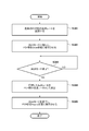
- FIG. 3 is a flowchart showing the processing of the STA 101 in this embodiment. It is assumed that the STA 101 receives a PCR beacon that the AP 102 periodically transmits when establishing a wireless connection with the AP 102.
- the PCR beacon transmitted from the AP 102 includes information indicating that the AP 102 is compatible with IEEE 802.11ba. Therefore, by receiving the PCR beacon, the STA 101 can determine that the AP 102 that has established the wireless connection is compatible with IEEE802.11ba.
- ASIC Application Specific Integrated Circuit
- the transmission rate setting unit 211 of the STA 101 sets the latest value of the transmission rate used when the PCR unit 208 in the Awake state transmits a frame (the transmission rate before (e.g. immediately before) starting the WUR mode).
- the data is recorded in the storage unit 201 (S301).
- the transmission rate in the present embodiment can be determined by MCS (Modulation and Coding Scheme (indexing a combination of a modulation scheme and a coding rate)) for transmission of a data frame.
- MCS Modulation and Coding Scheme
- the transmission rate can be determined by the number of spatial streams and the number of antennas. Therefore, the transmission rate can also be represented by the number of MCS or MIMO spatial streams.
- the STA 101 performs a shift process to the WUR mode with the AP 102 (S302).
- the WUR mode control unit 213 determines to shift the STA 101 to the WUR mode in response to an operation by the user or the STA 101 not transmitting data for a certain period of time.
- the PCR unit 208 of the STA 101 transmits an Enter WUR Mode Request frame, which is a request to start the WUR mode, to the AP 102.
- the Enter WUR Mode Request frame includes cycle information (Duty Cycle Period) indicating a cycle (reception interval) of a period in which the WUR unit 209 waits for a signal from the WUR of the AP 102.
- the AP 102 determines the reception interval included in the Enter WUR Mode Request frame received from the STA 101 as the WUR beacon transmission interval (WUR duty Cycle). Then, the AP 102 transmits an Enter WUR Mode Response frame including start timing information (Starting time of the WUR duty Cycle) indicating the start timing of the transmission interval.
- the PCR unit 208 of the STA 101 receives the Enter WUR Mode Response frame from the AP 102, and transmits the WUR Mode enter frame to the AP 102 if the contents, that is, the contents indicated by the start timing information are agreed. Then, the WUR mode control unit 213 causes the WUR unit 209 to start waiting for a signal at the timing based on the start timing information. Further, the WUR mode control unit 213 shifts the state of the PCR unit 208 to the Doze state (S302). In this way, the STA 101 shifts to the WUR mode. Note that the Enter WUR Mode Request frame and the Enter WUR Mode Response frame are both action frames that comply with the IEEE 802.11 series standard.
- the WUR unit 209 of the STA 101 receives the WUR beacon that the AP 102 regularly transmits, and the RSSI acquisition unit 212 acquires the RSSI of the beacon.
- the timing of receiving the WUR beacon is determined based on the cycle (reception interval) of the period in which the WUR unit 209 waits for a signal from the WUR unit of the AP 102 and the start timing information included in the Enter WUR Mode Response frame.
- the RSSI acquisition unit 212 further determines whether the WUR unit 209 succeeds in receiving the WUR frame based on the acquired RSSI.
- the successful reception of the WUR frame by the WUR unit 209 means the successful reception process including the decoding process for obtaining the signal decoded by the WUR unit 209.
- the RSSI acquisition unit 212 determines that the reception is successful when the RSSI value is equal to or more than a predetermined reception threshold, and determines that the reception fails when the RSSI value is less than the reception threshold.
- This reception threshold can be defined as, for example, the minimum reception sensitivity of the WUR unit 209 (for example, the reception signal strength with which the WUR unit 209 can decode a signal of the minimum transmission rate).
- the WUR mode control unit 213 determines whether to end the WUR mode (S303).
- the WUR mode control unit 213 makes the determination based on the presence/absence of data to be transmitted from the STA 101 to the AP 102, for example. In this case, the WUR mode control unit 213 determines that the WUR mode is to be terminated without continuing when there is data to be transmitted, and the WUR mode is to be continued when there is no data to be transmitted.
- the WUR mode control unit 213 can determine to end the WUR mode.
- the WUR mode control unit 213 may determine to end the WUR mode even when the WUR unit 209 has not succeeded in receiving the WUR beacon transmitted from the AP 102 even once over a predetermined period.
- the WUR mode control unit 213 sets the WUR mode It may be determined to end.
- the predetermined upper limit number is a numerical value that can be arbitrarily set depending on how much the communication failure that may suddenly occur is taken into consideration, and may be two or more times.
- the WUR mode will be terminated even if the communication state deteriorates for a moment.
- the WUR mode is ended after waiting for the state to stabilize. That is, there is a trade-off between responsiveness and power consumption. Therefore, for example, when the user selects whether to prioritize the responsiveness or the power consumption, and when the responsiveness is prioritized, the upper limit number of times is higher than when the power consumption is prioritized. Can be set less. Alternatively, the user may directly input the specified number of times. Further, when the battery level of the STA 101 is large, the upper limit number may be set smaller than when the battery level is low. Further, the upper limit number of times may be a fixed value preset in the STA 101.
- the transmission rate setting unit 211 stores in the storage unit 201 as the transmission rate used by the PCR unit 208 after the WUR mode ends (immediately after the WUR mode ends).
- the saved transmission rate is set (S304).
- the WUR mode control unit 213 ends the WUR mode, and shifts the state of the PCR unit 208 from the Doze state to the Awake state (S305). Shifting the state of the PCR unit 208 to the Awake state is also called activation.
- the STA 101 restarts communication with the AP 102 via the PCR unit 208.
- the WUR unit 209 continuously waits for reception of a WUR beacon from the AP 102.
- the PCR unit can perform communication at an appropriate transmission rate.
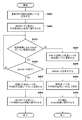
- FIG. 4 is a flowchart showing the processing of the STA 101 in this embodiment.
- the flowchart shown in FIG. 4 is realized by the control unit 202 reading and executing the program stored in the storage unit 201 of the STA 101. Further, some or all of the steps shown in the flowchart of FIG. 4 may be realized by hardware such as ASIC.
- the processing of S401 and S402 is the same as the processing of S301 and S302 of FIG.
- the WUR unit 209 tries to receive the WUR beacon for a predetermined period. Whether the reception of the WUR beacon is successful or unsuccessful is determined according to whether the RSSI of the received WUR beacon is equal to or more than a predetermined reception threshold or less, as in the first embodiment. If the WUR unit 209 has not succeeded in receiving the WUR beacon transmitted from the AP 102 even once during the predetermined period (No in S403), the WUR mode control unit 213 determines not to continue the WUR mode.
- the WUR mode control unit 213 determines whether to end the WUR mode (S404), as in S303 of FIG.
- the WUR mode is ended (Yes in S404)
- the same processing as S304 and S305 in FIG. 3 is performed. That is, the transmission rate setting unit 211 sets the transmission rate stored in the storage unit 201 as the transmission rate used by the PCR unit 208 after the WUR mode ends (S405), and the WUR mode control unit 213 ends the WUR mode. , Activates the PCR unit 208 (S406). If the WUR mode is not to be ended (No in S404), the process returns to S403 again.
- the transmission rate setting unit 211 updates (updates and records) the transmission rate recorded in the storage unit 201 in S401 to a transmission rate lower than the transmission rate (low transmission rate) (S407).
- the low transmission rate can be any low transmission rate such as the lowest transmission rate that the STA 101 can use.
- the low transmission rate may be set in the STA 101 in advance, or may be a transmission rate calculated by reducing the transmission rate recorded in S401 by a predetermined amount.
- the WUR mode control unit 213 ends the WUR mode (S408), and the transmission rate setting unit 211 sets the transmission rate (low transmission rate) updated in the storage unit 201 as the transmission rate of the PCR unit 208. (S409). After that, the WUR mode control unit 213 shifts the PCR unit 208 to the Awake state (S410).
- the transmission rate setting unit 211 proceeds to S405 in S405.
- a low transmission rate for recording may be set. Since it is expected that the communication environment is bad such that the received signal strength is low, the attempt to receive the signal a plurality of times can be expected to make the communication connection more reliable by lowering the transmission rate.
- the PCR unit can perform communication at an appropriate transmission rate after the PCR unit is activated after the WUR mode ends, depending on whether the WUR beacon is successfully received. ..
- a method of lowering the transmission rate in the STA 101 when the modulation signal deterioration due to the unstable power supply occurs will be described.
- the STA 101 has the configuration shown in FIGS. 2A and 2B, as in the first embodiment. Further, points different from the first embodiment will be described below.
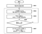
- FIGS. 5A and 5B are flowcharts showing the processing of the STA 101 in this embodiment.
- the flowcharts shown in FIGS. 5A and 5B are realized by the control unit 202 reading and executing the program stored in the storage unit 201 of the STA 101. Further, some or all of the steps shown in the flowcharts of FIGS. 5A and 5B may be realized by hardware such as ASIC.
- the STA 101 in the present embodiment operates so as to properly set the transmission rate even when a voltage fluctuation occurs. Note that the processing illustrated in FIGS. 5A and 5B is performed before the WUR mode control unit 213 ends the WUR mode (before Yes in S303 in FIG. 3 or before Yes in S404 in FIG. 4 or before S408). Be seen.
- the voltage measuring unit 214 measures the power supply voltage for a certain period (S501), and calculates the average value and the variance value of the voltage values during the certain period (S502). Subsequently, the voltage measuring unit 214 determines whether or not the calculated average value and variance value are within a predetermined average range and a predetermined dispersion range, respectively. When the calculated average value and variance value are not within the predetermined average range and the predetermined dispersion range (No in S503), the transmission rate setting unit 211 sets the transmission rate recorded in the storage unit 201 in S301 or S401 to the low The transmission rate is updated (S504).
- the low transmission rate may be determined based on the hardware characteristics of the STA 101 or the device evaluation result performed in advance, and may be set in the STA 101 in advance. Alternatively, the lowest transmission rate that the STA 101 can use may be used, or the transmission rate calculated by reducing the transmission rate recorded in the storage unit 201 by a predetermined amount may be used.
- FIG. 5B shows another processing example after the voltage measuring unit 214 calculates the average value and the variance value of the voltage values in a certain period.
- the processing of S501 and S502 is the same as that of FIG. 5A, and in S505, the voltage measurement unit 214 calculates the degree of decrease in the transmission rate from the calculated average value/dispersion value (S505).
- the voltage measuring unit 214 calculates how much the transmission rate recorded in the storage unit 201 is reduced according to the degree of deviation of the calculated average value from the expected value and the magnitude of the calculated variance value. To do. If the transmission rate decreases as a result of the calculation in S505 (Yes in S506), the transmission rate recorded in the storage unit 201 is updated (S507).
- the transmission rate updating process in S507 is similar to that in S504.
- the PCR unit can perform communication at an appropriate transmission rate after the PCR unit is activated after the WUR mode ends.
- the transmission rate is determined by the number of MCS or MIMO spatial streams and the number of antennas, but it may also be determined by the number of frames connected by frame aggregation and the number of channels bundled when channel bonding is used.
- the present invention supplies a program that implements one or more functions of the above-described embodiments to a system or apparatus via a network or a storage medium, and one or more processors in a computer of the system or apparatus read and execute the program. It can also be realized by the processing. It can also be realized by a circuit (for example, ASIC) that realizes one or more functions.
Landscapes
- Engineering & Computer Science (AREA)
- Computer Networks & Wireless Communication (AREA)
- Signal Processing (AREA)
- Mobile Radio Communication Systems (AREA)
Priority Applications (1)
| Application Number | Priority Date | Filing Date | Title |
|---|---|---|---|
| US17/231,037 US11523342B2 (en) | 2018-12-27 | 2021-04-15 | Communication apparatus, method of controlling the same, and non-transitory computer-readable storage medium |
Applications Claiming Priority (2)
| Application Number | Priority Date | Filing Date | Title |
|---|---|---|---|
| JP2018245382A JP7232042B2 (ja) | 2018-12-27 | 2018-12-27 | 通信装置、通信装置の制御方法、およびプログラム |
| JP2018-245382 | 2018-12-27 |
Related Child Applications (1)
| Application Number | Title | Priority Date | Filing Date |
|---|---|---|---|
| US17/231,037 Continuation US11523342B2 (en) | 2018-12-27 | 2021-04-15 | Communication apparatus, method of controlling the same, and non-transitory computer-readable storage medium |
Publications (1)
| Publication Number | Publication Date |
|---|---|
| WO2020137183A1 true WO2020137183A1 (ja) | 2020-07-02 |
Family
ID=71126556
Family Applications (1)
| Application Number | Title | Priority Date | Filing Date |
|---|---|---|---|
| PCT/JP2019/043634 Ceased WO2020137183A1 (ja) | 2018-12-27 | 2019-11-07 | 通信装置、通信装置の制御方法、およびプログラム |
Country Status (3)
| Country | Link |
|---|---|
| US (1) | US11523342B2 (https=) |
| JP (2) | JP7232042B2 (https=) |
| WO (1) | WO2020137183A1 (https=) |
Families Citing this family (2)
| Publication number | Priority date | Publication date | Assignee | Title |
|---|---|---|---|---|
| JP7232042B2 (ja) * | 2018-12-27 | 2023-03-02 | キヤノン株式会社 | 通信装置、通信装置の制御方法、およびプログラム |
| US11616547B2 (en) * | 2020-05-26 | 2023-03-28 | Mediatek Singapore Pte. Ltd. | Spatial configuration subfield designs of user field for MU-MIMO allocation in extreme-high-throughput systems |
Citations (4)
| Publication number | Priority date | Publication date | Assignee | Title |
|---|---|---|---|---|
| WO2016189933A1 (ja) * | 2015-05-27 | 2016-12-01 | ソニー株式会社 | 通信装置および通信方法 |
| US20170094600A1 (en) * | 2015-09-25 | 2017-03-30 | Intel Corporation | Apparatus, system and method of communicating a wakeup packet |
| JP2018113646A (ja) * | 2017-01-13 | 2018-07-19 | 株式会社東芝 | 無線通信装置 |
| WO2018172347A1 (en) * | 2017-03-20 | 2018-09-27 | Sony Mobile Communications Inc. | Wake-up radio technique |
Family Cites Families (13)
| Publication number | Priority date | Publication date | Assignee | Title |
|---|---|---|---|---|
| US20180234918A1 (en) | 2017-02-14 | 2018-08-16 | Qualcomm Incorporated | Wakeup radio synchronization techniques |
| US11849392B2 (en) * | 2017-05-05 | 2023-12-19 | Interdigital Patent Holdings, Inc. | Procedures and mechanisms for narrowband multi-channel transmission for wake up radios |
| WO2018237180A1 (en) * | 2017-06-21 | 2018-12-27 | Intel Corporation | Dynamic signature for wake-up packet authentication |
| US11647463B2 (en) * | 2017-09-13 | 2023-05-09 | Intel Corporation | Methods and arrangements to enable wake-up receiver for modes of operation |
| US10728856B2 (en) * | 2017-09-29 | 2020-07-28 | Intel IP Corporation | Methods and arrangements for wake-up radio operations |
| WO2019088645A1 (ko) * | 2017-10-30 | 2019-05-09 | 엘지전자 주식회사 | 무선 랜 시스템에서 프레임을 송신 또는 수신하는 방법 및 이를 위한 장치 |
| US11206607B2 (en) * | 2017-12-25 | 2021-12-21 | Panasonic Intellectual Property Corporation Of America | Communication apparatus and communication method for low power fast smart scanning |
| CN111989954A (zh) * | 2018-03-02 | 2020-11-24 | 交互数字专利控股公司 | 用于信道接入和恢复唤醒无线电的方法和装置 |
| US10779236B2 (en) * | 2018-04-11 | 2020-09-15 | Intel Corporation | Methods to encode a binary phase shift keying (BPSK) mark for a wake-up radio (WUR) packet |
| JP7320528B2 (ja) | 2018-04-16 | 2023-08-03 | パナソニック インテレクチュアル プロパティ コーポレーション オブ アメリカ | 通信装置および通信方法 |
| SG10201805402YA (en) * | 2018-06-22 | 2020-01-30 | Panasonic Ip Corp America | Communication apparatus and communication method for low power event monitoring |
| JP7232042B2 (ja) | 2018-12-27 | 2023-03-02 | キヤノン株式会社 | 通信装置、通信装置の制御方法、およびプログラム |
| JP7410163B2 (ja) * | 2019-02-28 | 2024-01-09 | インターデイジタル パテント ホールディングス インコーポレイテッド | Wur走査のための方法及びwtru |
-
2018
- 2018-12-27 JP JP2018245382A patent/JP7232042B2/ja active Active
-
2019
- 2019-11-07 WO PCT/JP2019/043634 patent/WO2020137183A1/ja not_active Ceased
-
2021
- 2021-04-15 US US17/231,037 patent/US11523342B2/en active Active
-
2023
- 2023-02-14 JP JP2023020970A patent/JP7546710B2/ja active Active
Patent Citations (4)
| Publication number | Priority date | Publication date | Assignee | Title |
|---|---|---|---|---|
| WO2016189933A1 (ja) * | 2015-05-27 | 2016-12-01 | ソニー株式会社 | 通信装置および通信方法 |
| US20170094600A1 (en) * | 2015-09-25 | 2017-03-30 | Intel Corporation | Apparatus, system and method of communicating a wakeup packet |
| JP2018113646A (ja) * | 2017-01-13 | 2018-07-19 | 株式会社東芝 | 無線通信装置 |
| WO2018172347A1 (en) * | 2017-03-20 | 2018-09-27 | Sony Mobile Communications Inc. | Wake-up radio technique |
Also Published As
| Publication number | Publication date |
|---|---|
| JP7232042B2 (ja) | 2023-03-02 |
| US20210235383A1 (en) | 2021-07-29 |
| JP2023053311A (ja) | 2023-04-12 |
| US11523342B2 (en) | 2022-12-06 |
| JP2020108020A (ja) | 2020-07-09 |
| JP7546710B2 (ja) | 2024-09-06 |
Similar Documents
| Publication | Publication Date | Title |
|---|---|---|
| US7991392B2 (en) | Communication system, information processing apparatus, and communication control method | |
| EP2849502A1 (en) | Communication method of a terminal and an access point for power saving | |
| US11832166B2 (en) | Communication apparatus, control method, and storage medium | |
| JP7546710B2 (ja) | 通信装置、通信装置の制御方法、およびプログラム | |
| US12074718B2 (en) | Communication apparatus, method of controlling communication apparatus, and non-transitory computer-readable storage medium | |
| US11729719B2 (en) | Communication apparatus, method of controlling the same, and non-transitory computer-readable storage medium for setting transmission rate | |
| WO2022194082A1 (zh) | 用于无线通信的电子设备和方法、计算机可读存储介质 | |
| JP7387258B2 (ja) | 通信装置、通信方法及びプログラム | |
| US20220078128A1 (en) | Communication apparatus, control method, and storage medium | |
| JP2009010502A (ja) | 無線データ通信システム、無線データ送信装置、無線データ受信装置 | |
| JP7277109B2 (ja) | 通信装置、制御方法、及びプログラム | |
| US11019681B2 (en) | Communication apparatus, control method, and storage medium | |
| US20250203031A1 (en) | Communication apparatus, method for controlling communication apparatus, and storage medium | |
| US20250203685A1 (en) | Communication apparatus and control method for controlling communication apparatus | |
| US12132534B2 (en) | Opportunistic sounding for low latency applications | |
| US20250203684A1 (en) | Communication apparatus, control method for controlling communication apparatus, and storage medium | |
| JP5990132B2 (ja) | 基地局装置、基地局のスリープ制御方法、及びプログラム | |
| US20250203525A1 (en) | A communication apparatus, a control method for controlling a communication apparatus, and a storage medium | |
| KR20260039771A (ko) | 통신 장치, 제어 방법, 및 저장 매체 | |
| JP2025096141A (ja) | 通信装置、通信装置の制御方法、及び、プログラム | |
| KR20230067419A (ko) | 전자 장치 및 이의 동작 방법 |
Legal Events
| Date | Code | Title | Description |
|---|---|---|---|
| 121 | Ep: the epo has been informed by wipo that ep was designated in this application |
Ref document number: 19904645 Country of ref document: EP Kind code of ref document: A1 |
|
| NENP | Non-entry into the national phase |
Ref country code: DE |
|
| 122 | Ep: pct application non-entry in european phase |
Ref document number: 19904645 Country of ref document: EP Kind code of ref document: A1 |