WO2020137165A1 - 圃場管理装置 - Google Patents
圃場管理装置 Download PDFInfo
- Publication number
- WO2020137165A1 WO2020137165A1 PCT/JP2019/043152 JP2019043152W WO2020137165A1 WO 2020137165 A1 WO2020137165 A1 WO 2020137165A1 JP 2019043152 W JP2019043152 W JP 2019043152W WO 2020137165 A1 WO2020137165 A1 WO 2020137165A1
- Authority
- WO
- WIPO (PCT)
- Prior art keywords
- field
- time
- work
- information
- positioning information
- Prior art date
- Legal status (The legal status is an assumption and is not a legal conclusion. Google has not performed a legal analysis and makes no representation as to the accuracy of the status listed.)
- Ceased
Links
Images





Classifications
-
- A—HUMAN NECESSITIES
- A01—AGRICULTURE; FORESTRY; ANIMAL HUSBANDRY; HUNTING; TRAPPING; FISHING
- A01B—SOIL WORKING IN AGRICULTURE OR FORESTRY; PARTS, DETAILS, OR ACCESSORIES OF AGRICULTURAL MACHINES OR IMPLEMENTS, IN GENERAL
- A01B69/00—Steering of agricultural machines or implements; Guiding agricultural machines or implements on a desired track
-
- G—PHYSICS
- G01—MEASURING; TESTING
- G01S—RADIO DIRECTION-FINDING; RADIO NAVIGATION; DETERMINING DISTANCE OR VELOCITY BY USE OF RADIO WAVES; LOCATING OR PRESENCE-DETECTING BY USE OF THE REFLECTION OR RERADIATION OF RADIO WAVES; ANALOGOUS ARRANGEMENTS USING OTHER WAVES
- G01S19/00—Satellite radio beacon positioning systems; Determining position, velocity or attitude using signals transmitted by such systems
- G01S19/01—Satellite radio beacon positioning systems transmitting time-stamped messages, e.g. GPS [Global Positioning System], GLONASS [Global Orbiting Navigation Satellite System] or GALILEO
- G01S19/13—Receivers
-
- G—PHYSICS
- G06—COMPUTING OR CALCULATING; COUNTING
- G06Q—INFORMATION AND COMMUNICATION TECHNOLOGY [ICT] SPECIALLY ADAPTED FOR ADMINISTRATIVE, COMMERCIAL, FINANCIAL, MANAGERIAL OR SUPERVISORY PURPOSES; SYSTEMS OR METHODS SPECIALLY ADAPTED FOR ADMINISTRATIVE, COMMERCIAL, FINANCIAL, MANAGERIAL OR SUPERVISORY PURPOSES, NOT OTHERWISE PROVIDED FOR
- G06Q50/00—Information and communication technology [ICT] specially adapted for implementation of business processes of specific business sectors, e.g. utilities or tourism
- G06Q50/02—Agriculture; Fishing; Forestry; Mining
Definitions
- the present invention relates to a field management device.
- Patent Document 1 when the position of the field in which the work is performed is recognized using the work machine equipped with the GPS positioning system, and the obtained field position recognition data is not already registered as the field position specifying data. Discloses a field position recognition system that registers the field position recognition data as new field position identification data.
- whether or not the field position recognition data is already registered as the field position specifying data is determined as follows. That is, when the field position recognition data is composed of position data of a plurality of vertices, the field position recognition data is determined based on whether or not there is a predetermined ratio or more in the field position specifying data. When the field position recognition data is composed of one position data, it is determined based on whether or not the field position recognition data is within a predetermined distance from the field position specifying data.
- the object of the present invention is to provide a field management device that makes it easy to identify the field where the work is performed by the work vehicle.
- An embodiment of the present invention stores the positioning information of a work vehicle positioned using a satellite positioning system, the positioning information including time information and position information in a planar space data type.
- a storage unit a second storage unit that stores field information for specifying the position of at least one field, and, for each field, the field among positioning information within a predetermined period in the first storage unit.
- a field management device including: an extraction unit that extracts positioning data included in a field; and a field identification unit that identifies a field on which the work vehicle has performed work, based on an extraction result of the extraction unit.
- the extraction unit uses the function to extract the positioning data included in the field from the positioning information within the predetermined period for each field. can do. Therefore, it becomes easy to identify the field where the work vehicle has performed the work.
- a working time calculation unit that further calculates a working time in the field based on the positioning information in the predetermined field extracted by the extraction unit is further included.
- the working time calculation unit determines the elapsed time from the earliest time to the latest time of the positioning information in the predetermined field extracted by the extraction unit as the work time in the field. calculate.
- the work time calculation unit is configured to, when the time interval between two positioning information temporally adjacent to each other in the predetermined field extracted by the extraction unit is a predetermined time or more, The work period on the front side of the working period of the field, which has the time information of the earlier positioning data of these two positioning data as the end time, and the later of the two positioning data in terms of time. It is configured to divide the time information of the one positioning data into the rear side work period having the start time and calculate the work time of each work period.
- an invalid portion is further included for invalidating the work time of the field having the shorter work time.
- FIG. 1 is a schematic diagram showing a configuration of a farm field management system to which a farm field management apparatus according to an embodiment of the present invention is applied.
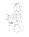
- FIG. 2 is a side view mainly showing the tractor.
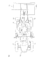
- FIG. 3 is a plan view of FIG.
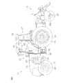
- FIG. 4 is a side view showing the tractor and the working machine, showing the working machine in a working state.
- FIG. 5 is a block diagram showing an electrical configuration of the tractor and the management server.
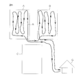
- FIG. 6 is a schematic diagram for explaining the outline of the operation of the information processing unit.
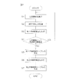
- FIG. 7 is a flowchart showing the overall procedure of information processing performed by the information processing unit.
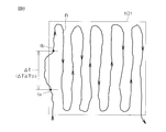
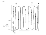
- FIG. 8 is a schematic diagram for explaining the outline of the first work period division processing.
- FIG. 1 is a schematic diagram showing a configuration of a farm field management system to which a farm field management apparatus according to an embodiment of the present invention is applied.
- FIG. 2 is a side view mainly showing the tractor.
- FIG. 3 is a plan view of
- FIG. 9 is a flowchart showing the procedure of the first work period division processing performed on the field of interest.
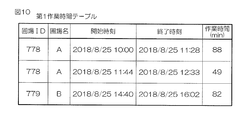
- FIG. 10 is a schematic diagram showing an example of the first work time table.
- FIG. 11 is a schematic diagram for explaining the outline of the second work period division processing.
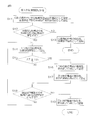
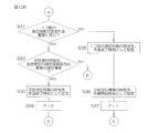
- FIG. 12A is a flowchart showing a part of the procedure of the second work period division processing.
- FIG. 12B is a flowchart showing a part of the procedure of the second work period division processing.
- FIG. 12C is a flowchart showing a part of the procedure of the second work period division processing.
- FIG. 13 is a schematic diagram showing an example of the second work time table.
- FIG. 14 is a schematic diagram for explaining an example of another process performed by the information processing unit.
- FIG. 1 is a schematic diagram showing a configuration of a field management system to which a field management apparatus according to an embodiment of the present invention is applied.
- the field management system 1 includes a communication terminal 2 mounted on a tractor 11 as a work vehicle, and a management server 3 as a field management device.
- a work machine 13 is attached to the tractor 11.
- the communication terminal 2 can communicate with the management server 3 via the communication network 5.
- the communication terminal 2 has a function of positioning the position of the tractor 11 using the positioning satellite 6.
- the communication terminal 2 transmits positioning information including time information and position information to the management server 3.
- the management server 3 is provided in the management center 4.
- the management server 3 receives the positioning information transmitted from the communication terminal 2.
- the management server 3 stores the received positioning information in the storage unit.
- FIG. 2 is a side view showing the tractor 11 and the working machine 13 mounted on the tractor 11, and showing the working machine 13 in a non-working state.
- FIG. 3 is a plan view of the tractor 11 and the working machine 13.
- FIG. 4 is a side view showing the tractor 11 and the working machine 13, and showing the working machine 13 in a working state.
- the tractor 11 includes a traveling machine body 12 as a vehicle body section that travels in the field.
- Various working machines such as a cultivator, a plow, a fertilizer applicator, a mower, and a seeder can be selected and mounted on the traveling machine body 12.
- a rotary cultivator is installed as the working machine 13.
- the traveling body 12 of the tractor 11 has its front portion supported by a pair of left and right front wheels 17 and its rear portion supported by a pair of left and right rear wheels 18.
- a hood 19 is placed in front of the traveling body 12.
- the engine 20, which is the drive source of the tractor 11, the fuel tank (not shown), etc. are accommodated in the bonnet 19.
- the engine 20 can be configured by, for example, a diesel engine, but is not limited to this, and may be configured by, for example, a gasoline engine.
- An electric motor may be adopted as a drive source instead of or in addition to the engine 20.
- a cabin 21 for a user to board is located behind the hood 19. Inside the cabin 21, there are arranged a steering handle 22 for a user to perform a steering operation, a seat 23 on which a user can sit, a communication terminal 2, various operating devices for performing various operations, and the like.
- the communication terminal 2 is detachably attached to the terminal support portion 16 fixed to the lower surface of the roof 15 of the cabin 21.
- the tractor 11 is not limited to the one with the cabin 21, and may have a configuration without the cabin 21.
- a chassis 30 of the tractor 11 is provided below the traveling body 12.
- the chassis 30 includes a body frame 31, a transmission 32, a front axle 33, a rear axle 34, and the like.
- the airframe frame 31 is a support portion in the front part of the tractor 11, and supports the engine 20 directly or via a vibration isolator.
- the transmission 32 changes the power from the engine 20 and transmits the power to the front axle 33 and the rear axle 34.
- the front axle 33 transmits the power input from the transmission 32 to the front wheels 17.
- the rear axle 34 transmits the power input from the transmission 32 to the rear wheels 18.
- a working machine 13 is attached to the rear part of the traveling machine body 12 of the tractor 11. By transmitting a part of the driving force of the engine 20 to the work implement 13 via a PTO shaft (not shown), the work implement 13 can be driven to perform the tilling work.
- a plurality of tillage claws (working bodies) 35 that are driven to rotate about a horizontally arranged shaft 35c are provided.
- the rotating plowing claws 35 come into contact with the soil, and the plowing work in the field can be performed at a predetermined depth corresponding to the working height. Further, the cultivating work can be stopped by stopping the rotation of the tilling claw 35 or raising the work implement 13 to the non-working height shown in FIG.
- FIG. 5 is a block diagram showing an electrical configuration of the tractor 11 and the management server 3.
- the tractor 11 includes the tractor control device 10 and the communication terminal 2 mounted on the tractor 11.
- the tractor control device 10 controls the operation of the traveling machine body 12 (forward, backward, stop, turning, etc.) and the operation of the working machine 13 (up/down, drive, stop, etc.).
- the tractor control device 10 is electrically connected to a plurality of controllers (not shown) for controlling each part of the tractor 11.
- the plurality of controllers are an engine controller that controls the rotation speed of the engine 20, a vehicle speed controller that controls the vehicle speed of the tractor 11, a steering controller that controls the turning angle of the front wheels 17 of the tractor 11, and a lifting/lowering of the work machine 13.
- a PTO axis controller for controlling the rotation of the PTO axis.
- the tractor control device 10 gives operation information to the communication terminal 2 at predetermined time intervals.
- the operation information includes engine on/off information, engine speed, exhaust temperature, accelerator operating state, brake operating state, and the like.
- the communication terminal 2 includes a control unit 40.
- a position detection unit 51, a communication unit 52, an operation display unit 53, an operation unit 54, a storage unit 55, etc. are connected to the control unit 40.
- the position detection unit 51 calculates the positioning information of the tractor 11 (communication terminal 2) based on the satellite positioning system.
- the satellite positioning system is, for example, a GNSS (Global Navigation Satellite System).
- the position detector 51 receives satellite signals from the plurality of positioning satellites 6 (see FIG. 1) and detects the positioning information of the tractor 11.
- the positioning information includes, for example, position information including latitude, longitude, and altitude information, and time information when the position information was acquired. In this embodiment, for convenience of description, the position information is assumed to include latitude information and longitude information.
- the storage unit 55 is provided with a positioning information storage unit 56 and the like.
- the communication unit 52 is a communication interface for the control unit 40 to communicate with the management server 3 via the communication network 5 (see FIG. 1).
- the operation display unit 53 is, for example, a touch panel display.
- the operation unit 54 includes, for example, one or a plurality of operation buttons.
- the storage unit 55 includes a storage device such as a non-volatile memory.
- the control unit 40 includes a microcomputer including a CPU and a memory (ROM, RAM, etc.) 41.
- the control unit 40 includes an information acquisition processing unit 42.
- the information acquisition processing unit 42 starts acquisition of the positioning information calculated by the position detection unit 51 when the engine is turned on. Then, the information acquisition processing unit 42 stores the acquired positioning information in the positioning information storage unit 56.
- the sampling interval of the positioning information is, for example, 1 minute. Then, when the engine is turned off, the information acquisition processing unit 42 stops the acquisition of positioning information and transmits the untransmitted positioning information stored in the positioning information storage unit 56 to the management server 3.
- the management server 3 includes a control unit 60.
- a communication unit 71, an operation display unit 72, an operation unit 73, a storage unit 74, etc. are connected to the control unit 60.
- the communication unit 71 is a communication interface for the control unit 60 to communicate with the communication terminal 2 via the communication network 5.
- the operation display unit 72 is, for example, a touch panel display.
- the operation unit 73 includes, for example, a keyboard and a mouse.
- the storage unit 74 is composed of a storage device such as a hard disk and a non-volatile memory.
- the storage unit 74 is provided with a positioning information storage unit (first storage unit) 75, a field information storage unit (second storage unit) 76, a first work time table storage unit 77, a second work time table storage unit 78, and the like. Has been.
- Positioning information received from the communication terminal 2 of the work vehicle 11 is stored in the positioning information storage unit 75 in the Geometry type of MYSQL (My Escuel) which is a plane space data type.
- MYSQL is the name of the database management system.
- the information acquisition processing unit 42 of the communication terminal 2 each time the engine of the work vehicle 11 is turned off, the time-series positioning information (hereinafter, referred to as “transmission unit”) acquired between the engine on and the engine off. (Referred to as “positioning information group”). Positioning information is stored in the positioning information storage unit 75 of the management server 3 so that the positioning information group of the transmission unit collectively transmitted and the positioning information group of the transmission unit collectively transmitted next can be distinguished. ..
- field position information for specifying the position of at least one field owned by the user is stored in the Geometry type of MYSQL, which is a plane space data type, for example.
- the field position information includes, for example, a field ID, a field name, and polygon data.
- the polygon data is composed of position information (latitude, longitude information) of a plurality of characteristic points for specifying the position of the field.
- the first working time table storage unit 77 stores a first working time table described later.
- the second work time table storage unit 78 stores a second work time table described later.
- the control unit 60 includes a microcomputer including a CPU and a memory (ROM, RAM, etc.) 61.
- the control unit 60 includes an information storage processing unit 62 and an information processing unit 63.
- the information storage processing unit 62 stores the received positioning information in the positioning information storage unit 75 in the Geometry type.
- the information processing unit 63 based on the positioning information within a predetermined period to be processed among the positioning information stored in the positioning information storage unit 75 and the field position information stored in the field information storage unit 76, The field in which the work is performed by the work vehicle 11 is specified, the working time in each field is calculated, and the working time table (first and second working time table) for each field is created.
- the positioning information within a predetermined period to be processed consists of one day's worth of positioning information (one day's worth of positioning information including the "positioning information group for each transmission unit").
- first processing target data the positioning information for one day to be processed will be collectively referred to as "first processing target data".
- the information processing unit 63 identifies the farm field A and the farm field B on which the work vehicle 11 has worked, and calculates the working time in the farm field A and the working time in the farm field B.
- the information processing unit 63 includes an extraction unit 63A, a field identification unit 63B, and a working time calculation unit 63C.
- the extraction unit 63A specifies, for each farm field stored in the farm field information storage unit 76, the positioning information included in the farm field in the first processing target data.
- the farm field specifying unit 63B specifies the farm field on which the work vehicle has performed work, based on the extraction result of the extracting unit 63A.
- the working time calculation unit 63C calculates the working time in the field based on the positioning information in the predetermined field extracted by the extraction unit 63A.
- FIG. 7 is a flowchart showing the overall procedure of information processing performed by the information processing unit 63.
- the information processing unit 63 selects one of the fields stored in the field information storage unit 76 as the field of interest from among the fields not selected as the field of interest in this information processing (step S1). ..
- the extraction unit 63A in the information processing unit 63 performs positioning information extraction processing for extracting the positioning information included in the field of interest from the first processing target data (step S2). Details of the positioning information extraction processing will be described later.
- step S3 the farm field specifying unit 63B and the working time calculating unit 63C in the information processing unit 63, based on the positioning information in the target farm field selected in step S2, perform a first working period partitioning process (hereinafter, referred to as “first partitioning”). Processing)) (step S3). Details of the first division processing will be described later.
- the information processing section 63 determines whether or not there is a field that has not been selected as the field of interest among the fields in the field information storage section 76 (step S4).
- step S4 If there is a field that has not been selected as the field of interest (step S4: YES), the information processing section 63 returns to step S1. In this case, the information processing unit 63 selects one field as the field of interest from among the fields not selected as the field of interest, and then performs the processing of steps S2 to S4 again.
- step S4 If it is determined in step S4 that there is no field that has not been selected as the field of interest (step S4: NO), the information processing section 63 proceeds to step S5.
- step S5 the farm field specifying unit 63B and the working time calculating unit 63C in the information processing unit 63 create a first working time table based on the first division processing result, and store the first working time table storage unit 77 in the first working time table storage unit 77.
- the first work time table will be described later.
- step S6 the second Work period division processing (hereinafter referred to as "second division processing") is performed (step S6). Details of the second division processing will be described later.
- the farm field specifying unit 63B and the working time calculating unit 63C in the information processing unit 63 create a second working time table based on the second division processing result and store it in the second working time table storage unit 78. (Step 7).
- the second work time table will be described later.
- the extraction unit 63A, the field identification unit 63B, and the working time calculation unit 63C in the information processing unit 63 will be referred to as the information processing unit 63 without distinction.
- step S2 the information processing section 63 issues, for example, the following geometry type function (select statement).
- the first processing target data stored in the positioning information storage unit 75 is designated as the positioning information list. List of fields.
- the polygon the polygon of the field of interest is designated.
- the positioning information included in the designated field of interest is selected from the designated first processing target data in the order of date and time and stored in the memory 61.
- step S3 of FIG. 7 the first division process in step S3 of FIG. 7 will be described.
- the traveling time corresponding to the traveling locus outside the field 101 is the same. It is preferable not to be included in the working time for.
- the time interval between the two positioning information is greater than that.
- the work periods are divided so that the front work period and the rear work period are recognized as separate work periods.
- the predetermined time Tth is, for example, 10 minutes.
- the work period from the end of the work in the farm field 101 until the work vehicle exits from the farm field 100 is the first period up to time ta and the time. It is divided into the second period after tb.
- the first period is a work period having a work end time at time ta
- the second period is a work period having a work start time at time tb.
- FIG. 9 is a flowchart showing the procedure of the first division processing (first work period division processing) performed on the field of interest.
- the positioning information included in the field of interest extracted in step S2 is collectively referred to as the second processing target data. Further, when the positioning information in the second processing target data is arranged in order from the earliest time, the earliest one of the two positioning information on both sides of the certain target positioning information is the target positioning information 1 The positioning information before one is referred to, and the one with the later time is referred to as the positioning information immediately after the attention positioning information.
- the information processing section 63 first sets the positioning information with the earliest time in the second processing target data as the attention positioning information, and sets the time of the attention positioning information in the memory 61 as the work start time. Set (step S11).
- the information processing section 63 determines whether or not the second processing target data includes positioning information whose time is later than the target positioning information (step S12).
- the information processing unit 63 stores the time of the target positioning information as the work end time with respect to the currently set work start time.
- the data is stored in 61 (step S13).
- the information processing section 63 ends the first demarcation process of this time. That is, when only one piece of positioning information is included in the second processing target data, the time information of the positioning information is stored as the work start time and the work end time, and the first delimitation processing of this time ends. To do.
- step S12 When it is determined in step S12 that the positioning information whose time is later than the target positioning information is present (step S12: YES), the information processing section 63 determines that one of the target positioning information pieces is included in the second processing target data.
- the previous positioning information is set as the attention positioning information (step S14). That is, the information processing section 63 updates the target positioning information.
- the information processing section 63 determines whether or not the time interval ⁇ T between the time point of the positioning information of interest and the time point of the immediately preceding positioning information is a predetermined time Tth or more (step S15).
- the predetermined time Tth is set to 10 minutes, for example.
- the information processing section 63 proceeds to step S18.
- step S15 when the time interval ⁇ T is equal to or longer than the predetermined time Tth (step S15: YES), the information processing section 63 sets the time of the positioning information immediately before the target positioning information to the currently set work start time. It is stored in the memory 61 as the work end time for (step S16). Then, the information processing section 63 sets the time of the target positioning information in the memory 61 as the work start time of the next work period (step S17). Then, the information processing section 63 proceeds to step S18.
- step S18 the information processing section 63 determines whether or not the second processing target data includes positioning information whose time is later than the target positioning information.
- step S18 If it is determined that there is positioning information whose time is later than the target positioning information (step S18: YES), the information processing section 63 returns to step S14. In this case, the focused positioning information is updated to the positioning information one step ahead in step S14, and the processing after step S15 is executed again for the updated focused positioning information.
- step S18 When it is determined in step S18 that the positioning information whose time is later than the target positioning information does not exist (step S18: NO), the information processing section 63 sets the time of the target positioning information to the currently set work. The work end time corresponding to the start time is stored in the memory 61 (step S19). Then, the information processing section 63 ends the first demarcation process of this time.
- FIG. 10 is a schematic diagram showing an example of the first work time table.
- the farm fields owned by the user are farm field A, farm field B, and farm field C as shown in FIG. 6, and one day's worth of fields when work is performed on farm field A and farm field B are shown.
- the example of 1 work time table is shown.
- the first work time table includes information on a field ID, a field name, a work start time (start time), a work end time (end time), and a work time (min).
- the work on the field A includes a first work and a second work.
- the working time of the first work is 88 minutes, and the working time of the second work is 49 minutes.
- step S6 of FIG. 7 Next, the second division process of step S6 of FIG. 7 will be described.
- the work period is divided when the time interval ⁇ T between two positioning information that are temporally adjacent in the second processing target data is a predetermined time Tth or more.
- the time interval ⁇ T between two positioning information that are temporally adjacent to each other is less than the predetermined time Tth, the work period is not divided. Therefore, for example, as shown by the travel loci R1 and R2 in FIG. 11, in the field 101, the engine of the work vehicle 11 is stopped between the time point tc and the time point td, and the stop time is less than the predetermined time Tth. In this case, the engine stop time is included in the working time.
- the work period is divided so that the engine stop time less than the predetermined time Tth is not included in the work time.
- 12A, 12B, and 12C are flowcharts showing the procedure of the second division processing (second work period division processing).
- the information processing unit 63 performs the second division process based on the first process target data and the first work time table.
- the positioning information in the first process target data is arranged in order from the earliest time point
- the earliest time point of the two positioning information points on both sides of the certain target positioning information point It is referred to as the immediately preceding positioning information
- the later one is referred to as the positioning information immediately after the attention positioning information.
- the information processing section 63 sets the positioning information with the earliest time in the first processing target data as the positioning information of interest (step S22).
- the information processing section 63 determines whether or not the focused positioning information is the positioning information in any of the fields based on the first work time table (step S23). Specifically, if the time of the focused positioning information is included in any of the work periods in the first working time table, the information processing section 63 causes the information processing unit 63 to determine the positioning information of the farm in which the focused positioning information is included. It is determined that
- the positioning information of interest is the positioning information in any of the fields (step S23: YES)
- the field including the positioning information of interest is specified, and the information (for example, field ID) of the field is stored in the memory 61. (Step S24).
- the start time flag F is reset (step S25): YES)
- the information processing section 63 sets the time of the target positioning information in the memory 61 as the work start time for the field specified in step S24. Yes (step S26).
- step S28 When the positioning information whose time is later than the target positioning information exists (step S28: YES), the information processing unit 63 selects the positioning information that is one ahead of the target positioning information in the first processing target data. After setting as positioning information (step S29), the process returns to step S23. As a result, the processing after step S23 is executed again for the new positioning information of interest.
- step S28 When it is determined in step S28 that there is no positioning information that is later in time than the target positioning information (step S28: NO), the information processing section 63 currently sets the time of the target positioning information. It is stored in the memory 61 as the work end time with respect to the work start time (step S30). Then, the information processing section 63 ends the second demarcation process of this time.
- the information processing unit 63 determines whether the target positioning information is the last positioning information in the positioning information group of the transmission unit including the target positioning information. Is determined (step S32). When the focused positioning information is the last positioning information in the positioning information group of the transmission unit (step S32: YES), the information processing section 63 sets the time of the focused positioning information to the currently set work start time. It is stored in the memory 61 as the work end time for (step S33).
- step S32 When it is determined in step S32 that the positioning information of interest is not the last positioning information in the positioning information group of the transmission unit (step S32: NO), the information processing section 63 proceeds to step S28 of FIG. 12A. Transition.
- step S31 When it is determined in step S31 that the field containing the target positioning information is different from the field containing the immediately preceding positioning information (step S31: NO), the information processing section 63 sets 1 of the target positioning information.
- the time of the immediately preceding positioning information is stored in the memory 61 as the work end time with respect to the work start time currently set (step S35).
- the information processing unit 63 sets the time of the attention positioning information in the memory 61 as the work start time for the field specified in step S24 (the field including the attention positioning information) (step S36).
- step S38 NO
- the information processing section 63 sets the time of the positioning information immediately before the target positioning information to the currently set work.
- the work end time corresponding to the start time is stored in the memory 61 (step S39).
- step S41 if it is determined that the positioning information whose time is later than the target positioning information is present (step S41: YES), the information processing section 63 proceeds to step S29 of FIG. 12A.
- FIG. 13 is a schematic diagram showing an example of the second work time table.
- FIG. 13 shows an example of the second work time table in the case where the first work time table has the contents shown in FIG.
- the second work time table includes information on the field ID, field, work start time (start time), work end time (end time), and work time (min).
- start time start time
- end time end time
- min work time
- the work period for the field B of FIG. 10 is divided into two. This is because there was an engine stop period of less than the predetermined time Tth (less than 10 minutes in this example) in the work period for the field B in FIG. 10, so the work period for the field B in FIG. This is because the period is divided into the period and the period on the rear side.
- the function is used to extract the positioning data included in the field from the positioning information within the predetermined period for each field. You can Therefore, it is easy to identify the field where the work is performed by the work vehicle and calculate the work time.
- the engine stop time can be excluded from the work time in the field.
- the information processing unit 63 may perform the processing described below after creating the first work time table. For example, as shown in FIG. 14, most of the travel track R of the work vehicle exists in the field 101, but a part of the running trajectory exists in the field 102 and in the field 102. It is assumed that the traveling time corresponding to the traveling locus is less than the predetermined time Tth.
- the traveling time corresponding to the traveling locus in the farm 102 is calculated as the working time for the farm 102 and at the same time included in the working time of the farm 101. That is, in the first working time table, as the working times of the farm field 101 and the farm field 102, there are working periods in which the working times overlap with each other. Therefore, in such a case, the information processing unit 63 compares the work time of the farm field 101 and the work time of the farm field 102 whose work times overlap with each other, and compares data of the shorter work time (in this example, , Data of the field 102) may be deleted from the first work time table. That is, the data having the shorter working time may be invalidated.
- data of the shorter work time in this example, Data of the field 102
- the information processing section 63 may omit the second division processing in step S6 and the second work time table creation processing in step S7 in FIG.
- the information processing section 63 may omit the first partitioning process of step S3, the second partitioning process of step S6, and the second work time table creating process of step S7 of FIG.
- the first working time table is created based on the result of the positioning information extraction processing for all fields. Therefore, in this case, the difference between the earliest time and the latest time of the positioning information included in the field is calculated as the working time in the field.
- the GNSS independent positioning system is used as the positioning system used in the communication terminal 2, but other than the independent positioning system such as RTK-GNSS (Real Time Kinematic GNSS).
- RTK-GNSS Real Time Kinematic GNSS
- a positioning system may be used.
- the work vehicle is a tractor, but the work vehicle may be a rice transplanter, combine harvester, civil/construction work equipment, snowplow, riding work implement, walk work implement, or the like.
- Farm Field Management System 2 Communication Terminal 3 Management Server 10 Tractor Control Device 11 Tractor (Work Vehicle) 60 control unit 61 memory 62 information storage processing unit 63 information processing unit 63A extraction unit 63B farm field identification unit 63C working time calculation unit 75 positioning information storage unit (first storage unit) 76 Field information storage unit (second storage unit) 77 First Working Time Table Storage Unit 78 Second Working Time Table Storage Unit
Landscapes
- Engineering & Computer Science (AREA)
- Life Sciences & Earth Sciences (AREA)
- Remote Sensing (AREA)
- Radar, Positioning & Navigation (AREA)
- General Physics & Mathematics (AREA)
- Physics & Mathematics (AREA)
- Business, Economics & Management (AREA)
- Tourism & Hospitality (AREA)
- Theoretical Computer Science (AREA)
- General Health & Medical Sciences (AREA)
- Human Resources & Organizations (AREA)
- Marketing (AREA)
- Primary Health Care (AREA)
- Strategic Management (AREA)
- Health & Medical Sciences (AREA)
- Mining & Mineral Resources (AREA)
- General Business, Economics & Management (AREA)
- Marine Sciences & Fisheries (AREA)
- Economics (AREA)
- Mechanical Engineering (AREA)
- Soil Sciences (AREA)
- Environmental Sciences (AREA)
- Animal Husbandry (AREA)
- Agronomy & Crop Science (AREA)
- Computer Networks & Wireless Communication (AREA)
- Guiding Agricultural Machines (AREA)
- Management, Administration, Business Operations System, And Electronic Commerce (AREA)
- Position Fixing By Use Of Radio Waves (AREA)
Abstract
管理サーバ3は、衛星測位システムを利用して測位された作業車両11の測位情報であって、時刻情報と位置情報とを含む測位情報を、平面空間データ型で記憶している第1記憶部75と、少なくとも1つの圃場の位置を特定するための圃場情報を記憶している第2記憶部76と、圃場毎に、第1記憶部75内における所定期間内の測位情報のうち、その圃場に含まれる測位データを抽出する抽出部63Aと、抽出部63Aの抽出結果に基づいて、作業車両が行った圃場を特定する圃場特定部63Bとを含む。
Description
この発明は、圃場管理装置に関する。
特許文献1には、GPS測位システムが搭載された作業機を用いて、作業が行われた圃場の位置を認識し、得られた圃場位置認識データが圃場位置特定データとして既に登録されていない場合には、当該圃場位置認識データを新規の圃場位置特定データとして登録する圃場位置認識システムが開示されている。
特許文献1では、圃場位置認識データが圃場位置特定データとして既に登録されているか否かは、次のようにして判定される。すなわち、圃場位置認識データが複数の頂点の位置データから構成される場合には、圃場位置認識データが圃場位置特定データ内に所定の割合以上あるか否かに基づいて判定される。圃場位置認識データが一つの位置データから構成される場合には、圃場位置認識データが、圃場位置特定データから所定の距離内にあるか否かに基づいて判定される。
この発明の目的は、作業車両によって作業が行われた圃場の特定が容易となる圃場管理装置を提供することである。
この発明の一実施形態は、衛星測位システムを利用して測位された作業車両の測位情報であって、時刻情報と位置情報とを含む測位情報を、平面空間データ型で記憶している第1記憶部と、少なくとも1つの圃場の位置を特定するための圃場情報を記憶している第2記憶部と、前記圃場毎に、前記第1記憶部内における所定期間内の測位情報のうち、その圃場に含まれる測位データを抽出する抽出部と、前記抽出部の抽出結果に基づいて、前記作業車両が作業を行った圃場を特定する圃場特定部とを含む、圃場管理装置を提供する。
この構成では、測位情報が平面空間データ型で記憶されているので、抽出部は、関数を利用して、圃場毎に、所定期間内の測位情報のうち、その圃場に含まれる測位データを抽出することができる。このため、作業車両によって作業が行われた圃場の特定が容易となる。
この発明の一実施形態では、前記抽出部によって抽出された所定の圃場内の測位情報に基づいて、当該圃場での作業時間を算出する作業時間算出部をさらに含む。
この発明の一実施形態では、前記作業時間算出部は、前記抽出部によって抽出された所定の圃場内の測位情報の最も早い時刻から最も遅い時刻までの経過時間を、当該圃場での作業時間として算出する。
この発明の一実施形態では、前記作業時間算出部は、前記抽出部によって抽出された所定の圃場内の時間的に隣り合う2つの測位情報の時間間隔が所定時間以上である場合には、当該圃場の作業期間を、これらの前記2つの測位データのうちの時間的に早い方の測位データの時刻情報を終了時刻とする前側の作業期間と、前記2つの測位データのうちの時間的に遅い方の測位データの時刻情報を開始時刻とする後側の作業期間とに分け、それぞれの作業期間の作業時間を算出するように構成されている。
この発明の一実施形態では、ある圃場に対する作業時間と他の圃場に対する作業時間とが重複している場合には、作業時間が短い方の圃場の作業時間を無効とする無効部をさらに含む。
本発明における上述の、またはさらに他の目的、特徴および効果は、添付図面を参照して次に述べる実施形態の説明により明らかにされる。
図1は、この発明の一実施形態に係る圃場管理装置が適用された圃場管理システムの構成を示す模式図である。
圃場管理システム1は、作業車両としてのトラクタ11に搭載された通信端末2と、圃場管理装置としての管理サーバ3とを含む。トラクタ11には作業機13が装着されている。通信端末2は、通信網5を介して、管理サーバ3と通信可能である。
通信端末2は、測位衛星6を利用してトラクタ11の位置を測位する機能を備えている。通信端末2は、時刻情報と位置情報を含む測位情報を管理サーバ3に送信する。管理サーバ3は、管理センター4内に設けられている。管理サーバ3は、通信端末2から送信されてきた測位情報を受信する。管理サーバ3は、受信した測位情報を記憶部に記憶する。
図2は、トラクタ11およびトラクタ11に装着された作業機13を示し、作業機13が非作業状態である様子を示す側面図である。図3は、トラクタ11および作業機13の平面図である。図4は、トラクタ11および作業機13を示し、作業機13が作業状態である様子を示す側面図である。
トラクタ11は、圃場内を走行する車体部としての走行機体12を備えている。走行機体12には、例えば、耕耘機、プラウ、施肥機、草刈機、播種機等の種々の作業機を選択して装着することができるようになっている。本実施形態においては、作業機13としてロータリ耕耘機が装着されている。
トラクタ11の走行機体12は、図2に示すように、その前部が左右1対の前輪17で支持され、その後部が左右1対の後輪18で支持されている。
走行機体12の前部にはボンネット19が配置されている。本実施形態では、このボンネット19内に、トラクタ11の駆動源であるエンジン20、燃料タンク(図示略)等が収容されている。このエンジン20は、例えばディーゼルエンジンにより構成することができるが、これに限るものではなく、例えばガソリンエンジンにより構成してもよい。また、駆動源として、エンジン20に代えてまたは加えて電気モータを採用してもよい。
ボンネット19の後方には、ユーザが搭乗するためのキャビン21が配置されている。このキャビン21の内部には、ユーザが操向操作するためのステアリングハンドル22、ユーザが着座可能な座席23、通信端末2、各種の操作を行うための様々な操作装置等が配置されている。通信端末2は、キャビン21の屋根15の下面に固定された端末支持部16に、着脱可能に装着されている。なお、トラクタ11は、キャビン21付きのものに限られず、キャビン21を備えていない構成であってもよい。
図2に示すように、走行機体12の下部には、トラクタ11のシャーシ30が設けられている。シャーシ30は、機体フレーム31、トランスミッション32、フロントアクスル33、リアアクスル34等から構成されている。
機体フレーム31は、トラクタ11の前部における支持部であって、直接または防振部材等を介してエンジン20を支持している。トランスミッション32は、エンジン20からの動力を変化させてフロントアクスル33およびリアアクスル34に伝達する。フロントアクスル33は、トランスミッション32から入力された動力を前輪17に伝達する。リアアクスル34は、トランスミッション32から入力された動力を後輪18に伝達する。
図2に示すように、トラクタ11の走行機体12の後部には作業機13が装着されている。エンジン20の駆動力の一部を図示しないPTO軸を介して作業機13に伝達することによって、作業機13を駆動して耕耘作業を行うことができる。作業機13の下部には、水平に配置された軸35cを中心に回転駆動される耕耘爪(作業体)35が複数設けられている。
この作業機13を図4に示す作業高さまで下降させることで、回転する耕耘爪35が土壌に接触し、当該作業高さに対応する所定深さでの圃場の耕耘作業を行うことができる。また、耕耘爪35の回転を停止したり、作業機13を図2に示す非作業高さまで上昇させたりすることで、耕耘作業を停止させることができる。
図5は、トラクタ11および管理サーバ3の電気的構成を示すブロック図である。
トラクタ11は、トラクタ制御装置10と、トラクタ11に搭載された通信端末2とを含む。トラクタ制御装置10には、走行機体12の動作(前進、後進、停止、旋回等の動作)と、作業機13の動作(昇降、駆動、停止等の動作)とを制御する。トラクタ制御装置10は、トラクタ11の各部を制御するための複数のコントローラ(図示略)が電気的に接続されている。複数のコントローラは、エンジン20の回転数等を制御するエンジンコントローラ、トラクタ11の車速を制御する車速コントローラ、トラクタ11の前輪17の転舵角を制御する操向コントローラ、作業機13の昇降を制御する昇降コントローラ、PTO軸の回転を制御するPTO軸コントローラ等を含む。
トラクタ制御装置10は、稼働情報を所定時間毎に通信端末2に与える。稼働情報には、エンジンオンオフ情報、エンジン回転数、排気温度、アクセルの操作状態、ブレーキの操作状態等が含まれる。
通信端末2は、制御部40を備えている。制御部40には、位置検出部51、通信部52、操作表示部53、操作部54、記憶部55等が接続されている。位置検出部51は、衛星測位システムに基づいてトラクタ11(通信端末2)の測位情報を算出する。衛星測位システムは、例えば、GNSS(Global Navigation Satellite System)である。具体的には、位置検出部51は、複数の測位衛星6(図1参照)からの衛星信号を受信して、トラクタ11の測位情報を検出する。測位情報は、例えば、緯度、経度および高度情報からなる位置情報と、当該位置情報が取得された時刻情報とからなる。この実施形態では、説明の便宜上、位置情報は、緯度情報および経度情報からなるものとする。記憶部55には、測位情報記憶部56等が設けられている。
通信部52は、制御部40が通信網5(図1参照)を介して管理サーバ3と通信するための通信インタフェースである。操作表示部53は、例えば、タッチパネル式ディスプレイからなる。操作部54は、例えば、1または複数の操作ボタンを含む。記憶部55は、不揮発性メモリ等の記憶デバイスから構成されている。
制御部40は、CPUおよびメモリ(ROM、RAM等)41を備えたマイクロコンピュータを含む。制御部40は、情報取得処理部42を含む。情報取得処理部42は、エンジンがオンされると、位置検出部51によって算出される測位情報の取得を開始する。そして、情報取得処理部42は、取得した測位情報を測位情報記憶部56に記憶する。測位情報のサンプリニング間隔は、例えば、1分である。そして、情報取得処理部42は、エンジンがオフされると、測位情報の取得を停止し、測位情報記憶部56に記憶されている未送信の測位情報を管理サーバ3に送信する。
管理サーバ3は、制御部60を備えている。制御部60には、通信部71、操作表示部72、操作部73、記憶部74等が接続されている。通信部71は、制御部60が通信網5を介して通信端末2と通信するための通信インタフェースである。操作表示部72は、例えば、タッチパネル式ディスプレイからなる。操作部73は、例えば、キーボード、マウス等を含む。記憶部74は、ハードディスク、不揮発性メモリ等の記憶デバイスから構成されている。
記憶部74には、測位情報記憶部(第1記憶部)75、圃場情報記憶部(第2記憶部)76、第1作業時間テーブル記憶部77、第2作業時間テーブル記憶部78等が設けられている。
測位情報記憶部75には、作業車両11の通信端末2から受信した測位情報が、例えば、平面空間データ型であるMYSQL(マイ・エスキューエル)のGeometry型で記憶される。MYSQLは、データベース管理システムの名称である。
前述したように、通信端末2の情報取得処理部42は、作業車両11のエンジンがオフされる毎に、エンジンオンからエンジンオフまでの間に取得した時系列の測位情報(以下、「送信単位の測位情報群」という)を一括して送信する。管理サーバ3の測位情報記憶部75には、一括送信される送信単位の測位情報群と、その次に一括送信される送信単位の測位情報群とを区別できるように、測位情報が記憶される。
圃場情報記憶部76には、ユーザが所有する少なくとも1つの圃場の位置を特定するための圃場位置情報が、例えば、平面空間データ型であるMYSQLのGeometry型で記憶される。圃場位置情報は、例えば、圃場IDと、圃場名と、ポリゴンデータとからなる。ポリゴンデータは、圃場の位置を特定するめための複数の特徴点の位置情報(緯度、経度情報)から構成される。
第1作業時間テーブル記憶部77には、後述する第1作業時間テーブルが記憶される。第2作業時間テーブル記憶部78には、後述する第2作業時間テーブルが記憶される。
制御部60は、CPUおよびメモリ(ROM、RAM等)61を備えたマイクロコンピュータを含む。制御部60は、情報記憶処理部62と情報処理部63とを含む。情報記憶処理部62は、通信端末2から測位情報を受信したときに、受信した測位情報を測位情報記憶部75にGeometry型で記憶する。
情報処理部63は、測位情報記憶部75に記憶されている測位情報のうち処理対象となる所定期間内の測位情報と、圃場情報記憶部76に記憶されている圃場位置情報とに基づいて、作業車両11によって作業が行われた圃場を特定するとともに、各圃場での作業時間を算出して、圃場毎の作業時間テーブル(第1および第2作業時間テーブル)を作成する。この実施形態では、処理対象となる所定期間内の測位情報は、1日分の測位情報(1日分の“送信単位の測位情報群”を含む測位情報)からなる。以下、処理対象となる1日分の測位情報を総称して「第1処理対象データ」ということにする。
例えば、図6に示すように、作業車両11のユーザは、圃場A、B、Cを所有しているものとする。そして、図6の走行軌跡Rで示されるように、ユーザの納屋Gを出発した作業車両11が、圃場Aおよび圃場Bに対して、その順番で作業を行った後、納屋Gに戻ったとする。情報処理部63は、作業車両11が作業を行った圃場Aおよび圃場Bを特定するとともに、圃場Aでの作業時間と圃場Bでの作業時間を算出する。
情報処理部63は、抽出部63Aと、圃場特定部63Bと、作業時間算出部63Cとを含む。抽出部63Aは、圃場情報記憶部76に記憶されている圃場毎に、第1処理対象データのうち、その圃場に含まれている測位情報を特定する。圃場特定部63Bは、抽出部63Aの抽出結果に基づいて、作業車両が作業を行った圃場を特定する。作業時間算出部63Cは、抽出部63Aによって抽出された所定の圃場内の測位情報に基づいて、当該圃場での作業時間を算出する。
図7は、情報処理部63によって行われる情報処理の全体的な手順を示すフローチャートである。
情報処理部63は、圃場情報記憶部76に記憶されている圃場のうち、今回の情報処理において注目圃場として選択されていない圃場の中から、1つの圃場を注目圃場として選択する(ステップS1)。
次に、情報処理部63内の抽出部63Aは、第1処理対象データのうち、注目圃場に含まれている測位情報を抽出するための測位情報抽出処理を行う(ステップS2)。測位情報抽出処理の詳細については、後述する。
次に、情報処理部63内の圃場特定部63Bおよび作業時間算出部63Cは、ステップS2で選択された注目圃場内の測位情報に基づいて、第1作業期間区切処理(以下、「第1区切処理」という)を行う(ステップS3)。第1区切処理の詳細については、後述する。
次に、情報処理部63は、圃場情報記憶部76内の圃場のうち、注目圃場として選択されていない圃場が存在するか否かを判別する(ステップS4)。
注目圃場として選択されていない圃場が存在する場合には(ステップS4:YES)、情報処理部63はステップS1に戻る。この場合、情報処理部63は、注目圃場として選択されていない圃場の中から1つの圃場を注目圃場として選択した後、ステップS2~ステップS4の処理を再度行う。
ステップS4において、注目圃場として選択されていない圃場が存在しないと判別された場合には(ステップS4:NO)、情報処理部63は、ステップS5に移行する。ステップS5では、情報処理部63内の圃場特定部63Bおよび作業時間算出部63Cは、第1区切処理結果に基づいて、第1作業時間テーブルを作成して、第1作業時間テーブル記憶部77に記憶する。第1作業時間テーブルについては、後述する。
次に、情報処理部63内の圃場特定部63Bおよび作業時間算出部63Cは、第1作業時間テーブルと、測位情報記憶部75に記憶されている第1処理対象データとに基づいて、第2作業期間区切処理(以下、「第2区切処理」という)を行う(ステップS6)。第2区切処理の詳細については、後述する。
最後に、情報処理部63内の圃場特定部63Bおよび作業時間算出部63Cは、第2区切処理結果に基づいて、第2作業時間テーブルを作成して、第2作業時間テーブル記憶部78に記憶する(ステップ7)。第2作業時間テーブルについては、後述する。
以下、図7のステップS2、S3、S5、S6およびS7の処理について、詳しく説明する。以下においては、情報処理部63内の抽出部63A、圃場特定部63Bおよび作業時間算出部63Cを区別することなく、情報処理部63ということにする。
まず、図7のステップS2の測位情報抽出処理について説明する。ステップS2では、情報処理部63は、例えば、次のようなgeometry型の関数(セレクト文)を発行する。
「SELECT 測位情報 FROM 測位情報リスト WHERE 圃場リスト.ポリゴン ORDER BY 日時」
この関数は、測位情報リストから、圃場リスト.ポリゴンに含まれる、測位情報を日時順に選択するための関数である。
この関数は、測位情報リストから、圃場リスト.ポリゴンに含まれる、測位情報を日時順に選択するための関数である。
測位情報リストして、測位情報記憶部75に記憶されている第1処理対象データが指定される。圃場リスト.ポリゴンとして、注目圃場のポリゴンが指定される。これにより、指定された第1処理対象データから、指定された注目圃場に含まれる測位情報が日時順で選択されて、メモリ61に記憶される。
次に、図7のステップS3の第1区切処理について説明する。例えば、図8に示すように、圃場101内の走行軌跡Rの一部が途切れて圃場外に存在しているような場合には、圃場外の走行軌跡に相当する走行時間が、当該圃場101に対する作業時間に含まれないようにすることが好ましい。
そこで、第1区切処理では、ステップS2で抽出された測位情報内の時間的に隣接する2つの測位情報の時間差が所定時間Tth以上である場合には、当該2つの測位情報の間期間よりも前側の作業期間と後側の作業期間とが別々の作業期間として認識されるように、作業期間が区切られる。所定時間Tthは、例えば10分である。図8の例では、圃場101内に作業車両が進入した後、圃場101内での作業が終了して圃場100から作業車両が退出するまでの作業期間が、時刻taまでの第1期間と時刻tb以降の第2期間に区切られる。第1期間は、時刻taを作業終了時刻とする作業期間であり、第2期間は時刻tbを作業開始時刻とする作業期間である。
図9は、注目圃場に対して行われる第1区切処理(第1作業期間区切処理)の手順を示すフローチャートである。
図9の説明においては、ステップS2で抽出された注目圃場に含まれる測位情報を総称して第2処理対象データということにする。また、第2処理対象データ内の測位情報を、時刻の早いものから順に並べた場合に、ある注目測位情報の両隣りにある2つの測位情報のうち、時刻が早い方を注目測位情報の1つ前の測位情報といい、時刻の遅い方を注目測位情報の1つ後の測位情報ということにする。
第1区切処理においては、情報処理部63は、まず、第2処理対象データのうち、時刻の最も早い測位情報を注目測位情報として設定し、注目測位情報の時刻を作業開始時刻としてメモリ61に設定する(ステップS11)。
次に、情報処理部63は、第2処理対象データ中に、注目測位情報よりも時刻の遅い測位情報が存在するか否かを判別する(ステップS12)。
注目測位情報よりも時刻の遅い測位情報が存在しない場合には(ステップS12:NO)、情報処理部63は、注目測位情報の時刻を、現在設定されている作業開始時刻に対する作業終了時刻としてメモリ61内に記憶する(ステップS13)。そして、情報処理部63は、今回の第1区切処理を終了する。つまり、第2処理対象データ内に1つの測位情報のみしか含まれていない場合には、当該測位情報の時刻情報が作業開始時刻および作業終了時刻として記憶されて、今回の第1区切処理が終了する。
ステップS12において、注目測位情報よりも時刻の遅い測位情報が存在すると判別された場合には(ステップS12:YES)、情報処理部63は、第2処理対象データのうち、注目測位情報の1つ先の測位情報を、注目測位情報として設定する(ステップS14)。つまり、情報処理部63は、注目測位情報を更新する。
次に、情報処理部63は、注目測位情報の時刻と1つ前の測位情報の時刻との時間間隔ΔTが、所定時間Tth以上であるか否かを判別する(ステップS15)。所定時間Tthは例えば10分に設定される。時間間隔ΔTが所定時間Tth未満である場合には(ステップS15:NO)、情報処理部63は、ステップS18進む。
一方、時間間隔ΔTが所定時間Tth以上である場合には(ステップS15:YES)、情報処理部63は、注目測位情報の1つ前の測位情報の時刻を、現在設定されている作業開始時刻に対する作業終了時刻としてメモリ61に記憶する(ステップS16)。この後、情報処理部63は、注目測位情報の時刻を、次の作業期間の作業開始時刻としてメモリ61に設定する(ステップS17)。そして、情報処理部63は、ステップS18に進む。
ステップS18では、情報処理部63は、第2処理対象データ中に、注目測位情報よりも時刻の遅い測位情報が存在するか否かを判別する。
注目測位情報よりも時刻の遅い測位情報が存在すると判別された場合には(ステップS18:YES)、情報処理部63は、ステップS14に戻る。この場合には、ステップS14において注目測位情報が1つ先の測位情報に更新され、更新後の注目測位情報に対して、ステップS15以降の処理が再度実行される。
ステップS18において、注目測位情報よりも時刻の遅い測位情報が存在しないと判別された場合には(ステップS18:NO)、情報処理部63は、注目測位情報の時刻を、現在設定されている作業開始時刻に対する作業終了時刻としてメモリ61に記憶する(ステップS19)。そして、情報処理部63は、今回の第1区切処理を終了する。
次に、図7のステップS5で作成される第1作業時間テーブルについて説明する。
図10は、第1作業時間テーブルの一例を示す模式図である。図10は、ユーザが所有する圃場が、図6に示すように、圃場A、圃場Bおよび圃場Cであり、圃場Aおよび圃場Bに対して作業が行われた場合の、1日分の第1作業時間テーブルの例を示している。
第1作業時間テーブルは、圃場ID、圃場名、作業開始時刻(開始時刻)、作業終了時刻(終了時刻)および作業時間(min)の情報からなる。図10の例では、圃場Aに対する作業として、1回目の作業と、2回目の作業とがある。1回目の作業の作業時間は、88分であり、2回目の作業の作業時間は、49分である。圃場Bに対する作業として、1回の作業があり、その作業時間は82分である。
次に、図7のステップS6の第2区切処理について説明する。
前述の第1区切処理では、第2処理対象データ内の時間的に隣接する2つの測位情報の時間間隔ΔTが所定時間Tth以上である場合には、作業期間が区切られる。しかし、時間的に隣接する2つの測位情報の時間間隔ΔTが所定時間Tth未満である場合には、作業期間は区切られない。このため、例えば、図11の走行軌跡R1,R2で示されるように、圃場101内において、時点tcと時点tdとの間で作業車両11のエンジンが停止し、その停止時間が所定時間Tth未満である場合には、エンジン停止時間も作業時間に含まれてしまう。
そこで、第2区切処理では、所定時間Tth未満のエンジン停止時間が作業時間に含まれないように、作業期間が区切られる。
図12A、図12Bおよび図12Cは、第2区切処理(第2作業期間区切処理)の手順を示すフローチャートである。
情報処理部63は、第1処理対象データと第1作業時間テーブルとに基づいて、第2区切処理を行う。以下において、第1処理対象データ内の測位情報を、時刻の早いものから順に並べた場合に、ある注目測位情報の両隣りにある2つの測位情報のうち、時刻の早い方を注目測位情報の1つ前の測位情報といい、時刻の遅い方を注目測位情報の1つ後の測位情報ということにする。
図12Aを参照して、情報処理部63は、まず、第2区切処理において作業開始時刻が現在設定されていることを記憶するための開始時刻フラグFをリセット(F=0)する(ステップS21)。第2区切処理においては、開始時刻フラグFは、作業開始時刻が設定されていない状態ではリセット(F=0)され、作業開始時刻が設定されている状態ではセット(F=1)される。
次に、情報処理部63は、第1処理対象データのうち、時刻の最も早い測位情報を注目測位情報として設定する(ステップS22)。
次に、情報処理部63は、第1作業時間テーブルに基づいて、注目測位情報がいずれかの圃場内の測位情報であるか否かを判別する(ステップS23)。具体的には、注目測位情報の時刻が、第1作業時間テーブル内のいずれかの作業期間内に含まれていれば、情報処理部63は、注目測位情報がいずれかの圃場内の測位情報であると判別する。
注目測位情報がいずれかの圃場内の測位情報である場合には(ステップS23:YES)、注目測位情報が含まれる圃場を特定し、当該圃場の情報(例えば圃場ID)をメモリ61に記憶する(ステップS24)。
次に、情報処理部63は、開始時刻フラグFがリセット(F=0)されているか否かを判別する(ステップS25)。開始時刻フラグFがリセットされている場合には(ステップS25):YES)、情報処理部63は、注目測位情報の時刻を、ステップS24で特定された圃場に対する作業開始時刻としてメモリ61内に設定する(ステップS26)。
この後、情報処理部63は、開始時刻フラグFをセット(F=1)する(ステップS27)。そして、情報処理部63は、第1処理対象データ中に、注目測位情報よりも時刻の遅い測位情報が存在するか否かを判別する(ステップS28)。
注目測位情報よりも時刻の遅い測位情報が存在する場合には(ステップS28:YES)、情報処理部63は、第1処理対象データのうち、注目測位情報の1つ先の測位情報を、注目測位情報として設定した後(ステップS29)、ステップS23に戻る。これにより、新たな注目測位情報に対して、ステップS23以降の処理が再度実行される。
前記ステップS28において、注目測位情報よりも時刻の遅い測位情報が存在しないと判別された場合には(ステップS28:NO)、情報処理部63は、注目測位情報の時刻を、現在設定されている作業開始時刻に対する作業終了時刻としてメモリ61に記憶する(ステップS30)。そして、情報処理部63は、今回の第2区切処理を終了する。
前記ステップS25において、開始時刻フラグFがセット(F=1)されていると判別された場合には(ステップS26:NO)、情報処理部63は、図12BのステップS31に移行する。ステップS31では、情報処理部63は、注目測位情報が含まれる圃場が、1つ前の測位情報が含まれる圃場と同じか否かを判別する。
両圃場が同じである場合には(ステップS31:YES)、情報処理部63は、注目測位情報が、当該注目測位情報を含む送信単位の測位情報群内の最後の測位情報であるか否かを判別する(ステップS32)。注目測位情報が、送信単位の測位情報群内の最後の測位情報である場合には(ステップS32:YES)、情報処理部63は、注目測位情報の時刻を、現在設定されている作業開始時刻に対する作業終了時刻としてメモリ61に記憶する(ステップS33)。
この後、情報処理部63は、開始時刻フラグFをリセット(F=0)する(ステップS34)。そして、情報処理部63は、図12AのステップS28に移行する。
前記ステップS32において、注目測位情報が、送信単位の測位情報群内の最後の測位情報ではないと判別された場合には(ステップS32:NO)、情報処理部63は、図12AのステップS28に移行する。
前記ステップS31において、注目測位情報が含まれる圃場が、1つ前の測位情報が含まれる圃場とは異なると判別された場合(ステップS31:NO)、情報処理部63は、注目測位情報の1つ前の測位情報の時刻を、現在設定されている作業開始時刻に対する作業終了時刻としてメモリ61に記憶する(ステップS35)。そして、情報処理部63は、注目測位情報の時刻を、ステップS24で特定された圃場(注目測位情報が含まれている圃場)に対する作業開始時刻としてメモリ61に設定する(ステップS36)。
この後、情報処理部63は、開始時刻フラグFをセット(F=1)する(ステップS37)。そして、情報処理部63は、図12AのステップS28に移行する。
図12Aの前記ステップS23において、注目測位情報が圃場内の測位情報ではないと判別された場合には(ステップS23:NO)、情報処理部63は、図12CのステップS38に移行する。ステップS38では、情報処理部63は、開始時刻フラグFがリセット(F=0)されているか否かを判別する。
開始時刻フラグFがセット(F=1)されている場合には(ステップS38:NO)、情報処理部63は、注目測位情報の1つ前の測位情報の時刻を、現在設定されている作業開始時刻に対する作業終了時刻としてメモリ61に記憶する(ステップS39)。
この後、情報処理部63は、開始時刻フラグFをリセット(F=0)する(ステップS40)。そして、情報処理部63は、第1処理対象データ中に、注目測位情報よりも時刻の遅い測位情報が存在するか否かを判別する(ステップS41)。注目測位情報よりも時刻の遅い測位情報が存在しない場合には(ステップS41:NO)、情報処理部63は、今回の第2区切処理を終了する。
前記ステップS41において、注目測位情報よりも時刻の遅い測位情報が存在すると判別された場合には(ステップS41:YES)、情報処理部63は、図12AのステップS29に移行する。
前記ステップS38において、開始時刻フラグFがリセット(F=0)されていると判別された場合には(ステップS38:YES)、情報処理部63は、ステップS41に移行する。
次に、図7のステップS7で作成される第2作業時間テーブルについて説明する。
図13は、第2作業時間テーブルの一例を示す模式図である。図13は、第1作業時間テーブルが図10に示すような内容である場合の、第2作業時間テーブルの例を示している。
第2作業時間テーブルは、圃場ID、圃場、作業開始時刻(開始時刻)、作業終了時刻(終了時刻)および作業時間(min)の情報からなる。図13の例では、図10の圃場Bに対する作業期間が、二つに分割されている。これは、図10の圃場Bに対する作業期間の中に、所定時間Tth未満(この例では10分未満)のエンジン停止期間があったため、図10の圃場Bに対する作業期間が、その停止期間の前側の期間と後側の期間とに分割されたためである。
前述の実施形態では、測位情報が平面空間データ型で記憶されているので、関数を利用して、圃場毎に、所定期間内の測位情報のうち、その圃場に含まれる測位データを抽出することができる。このため、作業車両によって作業が行われた圃場の特定および作業時間の算出が容易となる。
また、前述の実施形態では、例えば作業車両が圃場を逸脱した場合に、圃場を逸脱している時間を当該圃場の作業時間に含まれないようにすることが可能となる。
また、前述の実施形態では、圃場内で作業車両がエンジンを停止した場合に、エンジン停止時間を、当該圃場の作業時間に含まれないようにすることが可能となる。
以上、この発明の実施形態について説明したが、この発明はさらに他の形態で実施することもできる。
例えば、情報処理部63は、第1作業時間テーブルを作成した後に、以下に説明するような処理を行うようにしてもよい。例えば、図14に示すように、作業車両の走行軌Rの大部分は圃場101内に存在しているが、走行軌跡の途中の一部が圃場102内に存在しており、かつ圃場102内の走行軌跡に相当する走行時間が所定時間Tth未満であるような場合を想定する。
このような場合には、圃場102内の走行軌跡に相当する走行時間が、圃場102に対する作業時間として算出されると同時に、圃場101の作業時間にも含まれてしまう。つまり、第1作業時間テーブルにおいて、圃場101および圃場102それぞれの作業時間として、作業時刻が互いに重複した作業期間が存在することになる。そこで、このような場合には、情報処理部63は、作業時刻が互いに重複している圃場101の作業時間と圃場102の作業時間とを比較し、作業時間の短い方のデータ(この例では、圃場102のデータ)を、第1作業時間テーブルから削除するようにしてもよい。つまり、作業時間の短い方のデータを無効にしてもよい。
また、情報処理部63は、図7のステップS6の第2区切処理およびステップS7の第2作業時間テーブルの作成処理を省略してもよい。
また、情報処理部63は、図7のステップS3の第1区切処理、ステップS6の第2区切処理およびステップS7の第2作業時間テーブルの作成処理を省略してもよい。この場合には、全ての圃場に対する測位情報抽出処理の結果に基づいて、第1作業時間テーブルが作成される。したがって、この場合には、圃場内に含まれている測位情報のうち、最も早い時刻と最も遅い時刻との差が当該圃場での作業時間として算出されることになる。
また、前述の実施形態では、通信端末2に用いられている測位システムとして、GNSSの単独測位システムが用いられているが、RTK-GNSS(リアルタイム・キネマティクGNSS)等のような単独測位システム以外の測位システムを用いてもよい。
前述の実施形態では、作業車両はトラクタであるが、作業車両は、田植え機、コンバイン、土木・建設作業装置、除雪車、乗用型作業機、歩行型作業機等であってもよい。
本発明の実施形態について詳細に説明してきたが、これらは本発明の技術的内容を明らかにするために用いられた具体例に過ぎず、本発明はこれらの具体例に限定して解釈されるべきではなく、本発明の範囲は添付の請求の範囲によってのみ限定される。
この出願は、2018年12月27日に日本国特許庁に提出された特願2018-245757号に対応しており、その出願の全開示はここに引用により組み込まれるものとする。
1 圃場管理システム
2 通信端末
3 管理サーバ
10 トラクタ制御装置
11 トラクタ(作業車両)
60 制御部
61 メモリ
62 情報記憶処理部
63 情報処理部
63A 抽出部
63B 圃場特定部
63C 作業時間算出部
75 測位情報記憶部(第1記憶部)
76 圃場情報記憶部(第2記憶部)
77 第1作業時間テーブル記憶部
78 第2作業時間テーブル記憶部
2 通信端末
3 管理サーバ
10 トラクタ制御装置
11 トラクタ(作業車両)
60 制御部
61 メモリ
62 情報記憶処理部
63 情報処理部
63A 抽出部
63B 圃場特定部
63C 作業時間算出部
75 測位情報記憶部(第1記憶部)
76 圃場情報記憶部(第2記憶部)
77 第1作業時間テーブル記憶部
78 第2作業時間テーブル記憶部
Claims (5)
- 衛星測位システムを利用して測位された作業車両の測位情報であって、時刻情報と位置情報とを含む測位情報を、平面空間データ型で記憶している第1記憶部と、
少なくとも1つの圃場の位置を特定するための圃場情報を記憶している第2記憶部と、
前記圃場毎に、前記第1記憶部内における所定期間内の測位情報のうち、その圃場に含まれる測位データを抽出する抽出部と、
前記抽出部の抽出結果に基づいて、前記作業車両が作業を行った圃場を特定する圃場特定部とを含む、圃場管理装置。 - 前記抽出部によって抽出された所定の圃場内の測位情報に基づいて、当該圃場での作業時間を算出する作業時間算出部をさらに含む、請求項1に記載の圃場管理装置。
- 前記作業時間算出部は、前記抽出部によって抽出された所定の圃場内の測位情報の最も早い時刻から最も遅い時刻までの経過時間を、当該圃場での作業時間として算出する、請求項2に記載の圃場管理装置。
- 前記作業時間算出部は、前記抽出部によって抽出された所定の圃場内の時間的に隣り合う2つの測位情報の時間間隔が所定時間以上である場合には、当該圃場の作業期間を、これらの前記2つの測位データのうちの時間的に早い方の測位データの時刻情報を終了時刻とする前側の作業期間と、前記2つの測位データのうちの時間的に遅い方の測位データの時刻情報を開始時刻とする後側の作業期間とに分け、それぞれの作業期間の作業時間を算出するように構成されている、請求項2に記載の圃場管理装置。
- ある圃場に対する作業時間と他の圃場に対する作業時間とが重複している場合には、作業時間が短い方の圃場の作業時間を無効とする無効部をさらに含む、請求項4に記載の圃場管理装置。
Applications Claiming Priority (2)
| Application Number | Priority Date | Filing Date | Title |
|---|---|---|---|
| JP2018245757A JP7174619B2 (ja) | 2018-12-27 | 2018-12-27 | 圃場管理装置 |
| JP2018-245757 | 2018-12-27 |
Publications (1)
| Publication Number | Publication Date |
|---|---|
| WO2020137165A1 true WO2020137165A1 (ja) | 2020-07-02 |
Family
ID=71126537
Family Applications (1)
| Application Number | Title | Priority Date | Filing Date |
|---|---|---|---|
| PCT/JP2019/043152 Ceased WO2020137165A1 (ja) | 2018-12-27 | 2019-11-01 | 圃場管理装置 |
Country Status (2)
| Country | Link |
|---|---|
| JP (1) | JP7174619B2 (ja) |
| WO (1) | WO2020137165A1 (ja) |
Families Citing this family (2)
| Publication number | Priority date | Publication date | Assignee | Title |
|---|---|---|---|---|
| JP7638931B2 (ja) * | 2022-06-07 | 2025-03-04 | 株式会社クボタ | 管理システム |
| JP2025040479A (ja) | 2023-09-12 | 2025-03-25 | ヤンマーホールディングス株式会社 | 作業管理方法、作業管理システム、及び作業管理プログラム |
Citations (2)
| Publication number | Priority date | Publication date | Assignee | Title |
|---|---|---|---|---|
| JP2015069450A (ja) * | 2013-09-30 | 2015-04-13 | 株式会社日立ソリューションズ | 圃場管理装置 |
| JP2018160257A (ja) * | 2014-07-16 | 2018-10-11 | 株式会社リコー | システム、機械、制御方法、プログラム |
Family Cites Families (1)
| Publication number | Priority date | Publication date | Assignee | Title |
|---|---|---|---|---|
| JP6645478B2 (ja) | 2017-05-30 | 2020-02-14 | 井関農機株式会社 | 農作業支援システム |
-
2018
- 2018-12-27 JP JP2018245757A patent/JP7174619B2/ja active Active
-
2019
- 2019-11-01 WO PCT/JP2019/043152 patent/WO2020137165A1/ja not_active Ceased
Patent Citations (2)
| Publication number | Priority date | Publication date | Assignee | Title |
|---|---|---|---|---|
| JP2015069450A (ja) * | 2013-09-30 | 2015-04-13 | 株式会社日立ソリューションズ | 圃場管理装置 |
| JP2018160257A (ja) * | 2014-07-16 | 2018-10-11 | 株式会社リコー | システム、機械、制御方法、プログラム |
Also Published As
| Publication number | Publication date |
|---|---|
| JP7174619B2 (ja) | 2022-11-17 |
| JP2020107112A (ja) | 2020-07-09 |
Similar Documents
| Publication | Publication Date | Title |
|---|---|---|
| JP7219309B2 (ja) | 情報取得装置および情報管理システム | |
| JP6719395B2 (ja) | 自動走行作業車 | |
| JP7281123B2 (ja) | 作業情報生成装置 | |
| WO2020129704A1 (ja) | 走行作業機 | |
| JP7607016B2 (ja) | 作業情報管理装置 | |
| JP7849542B2 (ja) | 測位方法、作業車両、及び測位システム | |
| JP7270534B2 (ja) | 作業種別推定装置 | |
| JP7756167B2 (ja) | 農業支援システムおよび農業支援方法 | |
| WO2020137165A1 (ja) | 圃場管理装置 | |
| JP6772105B2 (ja) | 作業管理システム | |
| JP6622131B2 (ja) | 経路生成装置 | |
| JP2020099225A (ja) | 走行作業機 | |
| JP2021006045A (ja) | 圃場管理装置 | |
| CN111867352B (zh) | 田地管理装置 | |
| JP2023079152A (ja) | 経路生成方法、経路生成システム、及び経路生成プログラム | |
| EP4528611A1 (en) | Work management method, work management program, and work management system | |
| JP2020106978A (ja) | 走行支援装置、走行支援装置を備えた作業車両及び走行支援方法 | |
| EP4144195A1 (en) | Automatic traveling method, automatic traveling system, and automatic traveling program | |
| US20240172581A1 (en) | Setting Method, Automatic Traveling Method, Setting System, And Setting Program | |
| JP7050874B2 (ja) | 作業管理システム | |
| JP6960975B2 (ja) | 経路生成システム | |
| JP2020099227A (ja) | 走行作業機 | |
| JP2021132591A (ja) | 経路作成管理システム | |
| JP2025051102A (ja) | 作業管理方法、作業管理プログラム、及び作業管理システム | |
| JP6995711B2 (ja) | 作業機の測位システム |
Legal Events
| Date | Code | Title | Description |
|---|---|---|---|
| 121 | Ep: the epo has been informed by wipo that ep was designated in this application |
Ref document number: 19902272 Country of ref document: EP Kind code of ref document: A1 |
|
| NENP | Non-entry into the national phase |
Ref country code: DE |
|
| 122 | Ep: pct application non-entry in european phase |
Ref document number: 19902272 Country of ref document: EP Kind code of ref document: A1 |