WO2020137115A1 - 車載処理装置、位置推定方法、出庫システム - Google Patents
車載処理装置、位置推定方法、出庫システム Download PDFInfo
- Publication number
- WO2020137115A1 WO2020137115A1 PCT/JP2019/041175 JP2019041175W WO2020137115A1 WO 2020137115 A1 WO2020137115 A1 WO 2020137115A1 JP 2019041175 W JP2019041175 W JP 2019041175W WO 2020137115 A1 WO2020137115 A1 WO 2020137115A1
- Authority
- WO
- WIPO (PCT)
- Prior art keywords
- vehicle
- coordinate system
- processing device
- information
- point
- Prior art date
- Legal status (The legal status is an assumption and is not a legal conclusion. Google has not performed a legal analysis and makes no representation as to the accuracy of the status listed.)
- Ceased
Links
Images







Classifications
-
- B—PERFORMING OPERATIONS; TRANSPORTING
- B60—VEHICLES IN GENERAL
- B60W—CONJOINT CONTROL OF VEHICLE SUB-UNITS OF DIFFERENT TYPE OR DIFFERENT FUNCTION; CONTROL SYSTEMS SPECIALLY ADAPTED FOR HYBRID VEHICLES; ROAD VEHICLE DRIVE CONTROL SYSTEMS FOR PURPOSES NOT RELATED TO THE CONTROL OF A PARTICULAR SUB-UNIT
- B60W30/00—Purposes of road vehicle drive control systems not related to the control of a particular sub-unit, e.g. of systems using conjoint control of vehicle sub-units
- B60W30/06—Automatic manoeuvring for parking
-
- G—PHYSICS
- G01—MEASURING; TESTING
- G01C—MEASURING DISTANCES, LEVELS OR BEARINGS; SURVEYING; NAVIGATION; GYROSCOPIC INSTRUMENTS; PHOTOGRAMMETRY OR VIDEOGRAMMETRY
- G01C21/00—Navigation; Navigational instruments not provided for in groups G01C1/00 - G01C19/00
- G01C21/26—Navigation; Navigational instruments not provided for in groups G01C1/00 - G01C19/00 specially adapted for navigation in a road network
- G01C21/28—Navigation; Navigational instruments not provided for in groups G01C1/00 - G01C19/00 specially adapted for navigation in a road network with correlation of data from several navigational instruments
Definitions
- the present invention relates to an in-vehicle processing device, a position estimation method, and a shipping system.
- Patent Document 1 discloses a storage unit that stores point cloud data including a plurality of coordinates of a point that represents a part of an object in a first coordinate system, and a sensor input that acquires an output of a sensor that acquires information about the surroundings of a vehicle.
- a movement information acquisition part that acquires information about the movement of the vehicle, the sensor input part, and a part of the object of the vehicle in the second coordinate system based on the information acquired by the movement information acquisition part.
- a local peripheral information creating unit that generates local peripheral information including a plurality of coordinates in the second coordinate system of a point representing the point, and the first coordinate system and the second coordinate based on the point cloud data and the local peripheral information.
- An in-vehicle processing device is disclosed, which includes a position estimation unit that estimates a relationship between systems and estimates a position of the vehicle in the first coordinate system.
- a vehicle-mounted processing device acquires a storage unit that stores point cloud data including a plurality of coordinates in a first coordinate system of a point that represents a part of an object, and information around a vehicle. Based on the information that the sensor input unit that acquires the output of the sensor, the movement information acquisition unit that acquires the vehicle movement information that is the information regarding the movement of the vehicle, the sensor input unit, and the movement information acquisition unit, A local peripheral information creating unit that generates local peripheral information that includes a plurality of coordinates in the second coordinate system of a position of the vehicle in the second coordinate system and a part of the object, the point cloud data, and the local periphery.
- a position estimating unit that estimates a relationship between the first coordinate system and the second coordinate system based on information, and estimates a position of the vehicle in the first coordinate system.
- the travel route of the vehicle in one coordinate system is included, and the position estimation unit assumes that the vehicle is traveling on the travel route included in the point cloud data, and the first coordinate system and the second coordinate system.
- Estimate system relationships A position estimation method according to a second aspect of the present invention obtains information about a storage unit that stores point cloud data including a plurality of coordinates in a first coordinate system of a point that represents a part of an object, and information about the surroundings of a vehicle.
- a position estimation method executed by an in-vehicle processing device provided in the vehicle comprising: a sensor input unit that acquires an output of a sensor; and a movement information acquisition unit that acquires vehicle movement information that is information related to movement of the vehicle, Based on the information acquired by the sensor input unit and the movement information acquisition unit, local peripheral information including a plurality of coordinates in the second coordinate system of a position of the vehicle in the second coordinate system and a point representing a part of the object is acquired.
- a shipping system is a shipping system including an in-vehicle processing device mounted on a vehicle and a mobile terminal that communicates with the in-vehicle processing device, wherein the mobile terminal is the first in-vehicle processing device.
- the vehicle-mounted processing device includes a storage unit that stores point cloud data that includes a plurality of coordinates in a first coordinate system of a point that represents a part of an object, and a surrounding area of the vehicle.
- the sensor input unit that acquires the output of the sensor that acquires the information
- the movement information acquisition unit that acquires the vehicle movement information that is the information related to the movement of the vehicle, the sensor input unit, and the movement information acquisition unit that acquire
- a local surrounding information creating unit that creates, based on the information, local surrounding information including a plurality of coordinates in the second coordinate system of a position of the vehicle in the second coordinate system and a part of the object; and the point cloud data.
- a position estimation unit that estimates the relationship between the first coordinate system and the second coordinate system based on the local peripheral information and estimates the position of the vehicle in the first coordinate system. Includes a travel route of the vehicle in the first coordinate system and a starting position of the vehicle in the first coordinate system, and the position estimation unit causes the vehicle to travel on a travel route included in the point cloud data.
- the on-vehicle processing device uses the position estimation unit to perform the first operation.
- a response unit that estimates the position of the vehicle in the coordinate system and causes the vehicle to travel along the travel route in a direction away from the starting position.
- the accuracy of position identification can be improved and the calculation time can be shortened.
- FIG. 3 is a diagram illustrating an angle limited comparison and a movement limited comparison.
- FIG. 17 Flowchart showing details of automatic parking processing
- Overall configuration diagram of automatic parking system 100A according to the second embodiment Flowchart showing the process of automatic shipping phase
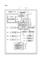
- FIG. 1 is a configuration diagram of an automatic parking system 100 including an in-vehicle processing device according to the present invention.
- the automatic parking system 100 is mounted on the vehicle 1.
- the automatic parking system 100 includes sensor groups 102, 107 to 109, input/output device groups 110, 111, 114, control device groups 130 to 133 that control the vehicle 1, and an in-vehicle processing device 120.
- the sensor group, the input/output device group, and the control device group are connected to the in-vehicle processing device 120 by a signal line and exchange various data with the in-vehicle processing device 120.
- a person who gets on the vehicle 1 is referred to as a “user”.
- the on-vehicle processing device 120 includes a calculation unit 121, a RAM 122, a ROM 123, a storage unit 124, and an interface 125.
- the in-vehicle processor 120 is, for example, an ECU (Electronic Control Unit).
- the arithmetic unit 121 is a CPU. You may comprise so that other arithmetic processing devices, such as FPGA, may perform all or a part of arithmetic processing.
- the RAM 122 is a readable/writable storage area and operates as a main storage device of the in-vehicle processing device 120.
- the RAM 122 stores local peripheral information 122A described later.
- the ROM 123 is a read-only storage area, and stores programs to be described later.
- This program is expanded in the RAM 122 and executed by the arithmetic unit 121.
- the arithmetic unit 121 operates as the point cloud data acquisition unit 121A, the local peripheral information creation unit 121B, and the position estimation unit 121C by reading and executing the program.
- the storage unit 124 is a non-volatile storage device, and operates as an auxiliary storage device of the in-vehicle processing device 120.
- the storage unit 124 stores a parking lot point cloud 124A.
- the parking lot point cloud 124A is one or a plurality of parking lot data.
- the parking lot data is a set of position information of a certain parking lot, that is, the latitude/longitude, coordinates indicating a parking area, and coordinates of points forming a landmark existing in the parking lot. The landmark will be described later.
- the interface 125 exchanges information with the in-vehicle processing device 120 and other devices that form the automatic parking system 100.
- the interface 125 acquires the output of the camera 102 that acquires the information around the vehicle 1, it can also be called a sensor input unit. Further, the interface 125 acquires information about the movement of the vehicle 1 from the vehicle speed sensor 108 and the steering angle sensor 109, and thus can be called a movement information acquisition unit.
- the sensor group includes a camera 102 for taking a picture around the vehicle 1, a GPS receiver 107, a vehicle speed sensor 108, and a steering angle sensor 109.
- the camera 102 outputs an image obtained by photographing (hereinafter, photographed image) to the in-vehicle processing device 120.
- the in-vehicle processing device 120 uses a captured image of the camera 102 to perform landmark positioning, which will be described later. Internal parameters such as the focal length of the camera 102 and the size of the image pickup element, and external parameters such as the mounting position and mounting posture of the camera 102 on the vehicle 1 are known and stored in the ROM 123 in advance.
- the in-vehicle processing device 120 can calculate the positional relationship between the subject and the camera 102 using the internal parameter and the external parameter stored in the ROM 123.
- the GPS receiver 107 receives signals from a plurality of satellites forming the satellite navigation system, and calculates the position of the GPS receiver 107 in the geodetic system, that is, the latitude and longitude by calculation based on the received signals.
- the accuracy of the latitude and longitude calculated by the GPS receiver 107 does not have to be high, and may include an error of, for example, several m to 10 m.
- the GPS receiver 107 outputs the calculated latitude and longitude to the in-vehicle processing device 120.
- the vehicle speed sensor 108 and the steering angle sensor 109 respectively measure the vehicle speed and the steering angle of the vehicle 1 and output them to the in-vehicle processing device 120.
- the on-vehicle processor 120 calculates the amount of movement and the direction of movement of the vehicle 1 by the known dead reckoning technique using the outputs of the vehicle speed sensor 108 and the steering angle sensor 109.
- the user inputs an operation command to the in-vehicle processing device 120 to the input device 110.
- the input device 110 includes a recording start button 110A, a recording completion button 110B, and an automatic parking button 110C.
- the display device 111 is, for example, a liquid crystal display, and displays information output from the in-vehicle processing device 120. It should be noted that the input device 110 and the display device 111 may be integrally configured as, for example, a liquid crystal display corresponding to a touch operation. In this case, it may be determined that the recording start button 110A, the recording completion button 110B, or the automatic parking button 110C is pressed by touching a predetermined area of the liquid crystal display.
- the communication device 114 is used for wirelessly exchanging information between the device outside the vehicle 1 and the in-vehicle processing device 120. For example, when the user is outside the vehicle 1, it communicates with a mobile terminal worn by the user to exchange information.
- the target with which the communication device 114 communicates is not limited to the mobile terminal of the user.
- the vehicle control device 130 controls the steering device 131, the drive device 132, and the braking device 133 based on the operation command of the in-vehicle processing device 120.
- the steering device 131 operates the steering of the vehicle 1.
- the drive device 132 gives a driving force to the vehicle 1.
- the drive device 132 increases the driving force of the vehicle 1 by increasing the target rotation speed of the engine included in the vehicle 1, for example.
- the braking device 133 applies a braking force to the vehicle 1.
- a landmark is an object having a characteristic that can be identified by a sensor, and is, for example, a parking frame line which is one type of road surface paint, a building wall which is an obstacle that obstructs the running of a vehicle, or the like. In the present embodiment, a vehicle or a person who is a moving body is not included in the landmark.
- the in-vehicle processing device 120 detects a landmark existing around the vehicle 1, that is, a point having a feature identifiable by a sensor, based on the information input from the camera 102.
- the detection of the landmark based on the information input from the external sensor, that is, the camera 102 is referred to as “landmark positioning”.
- the in-vehicle processing device 120 detects a road surface paint such as a parking frame by operating an image recognition program as follows with respect to a captured image of the camera 102.
- the parking frame is detected by first extracting edges from the input image with a Sobel filter or the like. Next, for example, a pair of a rising edge that is a change from white to black and a falling edge that is a change from black to white is extracted. Then, when the interval of this pair substantially matches the first predetermined distance, that is, the thickness of the white line forming the parking frame, this pair is made a candidate for the parking frame.
- a plurality of parking frame candidates are detected by similar processing, and if the interval between the parking frame candidates is substantially equal to the second predetermined distance, that is, the interval between the white lines of the parking frame, they are detected as a parking frame. ..
- Road surface paints other than parking frames are detected by an image recognition program that executes the following processing. First, an edge is extracted from the input image with a Sobel filter or the like. It can be detected by searching for a pixel in which the edge strength is larger than a predetermined constant value and the interval between the edges is a predetermined distance corresponding to the width of the white line.
- the on-vehicle processor 120 detects a vehicle or a person by known template matching, for example, and excludes it from the measurement result. Moreover, you may exclude the moving body detected as follows from the measurement result. That is, the in-vehicle processing device 120 calculates the positional relationship between the subject and the camera 102 in the captured image using the internal parameter and the external parameter. Next, the vehicle-mounted processing device 120 calculates the relative speeds of the vehicle 1 and the subject by tracking the subject in the captured images continuously acquired by the camera 102. Finally, the in-vehicle processing device 120 calculates the speed of the vehicle 1 using the outputs of the vehicle speed sensor 108 and the steering angle sensor 109, and determines that the subject is a moving body if it does not match the relative velocity with the subject. , Excludes information about this mobile from the measurement results.
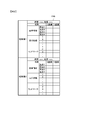
- FIG. 2 is a diagram showing an example of a parking lot point group 124A stored in the storage unit 124.
- FIG. 2 shows an example in which two parking lot data are stored as the parking lot point group 124A.
- One piece of parking lot data is the position of the parking lot, that is, the latitude and longitude (hereinafter referred to as latitude and longitude), the coordinates of the parking area, the traveling route of the vehicle 1, and the two-dimensional plane of the points forming the landmark. It consists of the above coordinates.
- the location of the parking lot is, for example, near the entrance of the parking lot, near the center of the parking lot, or the latitude and longitude of the parking position.
- the coordinates of the parking area, the traveling route of the vehicle 1, and the coordinates of the points forming the landmark are coordinates in the coordinate system specific to the parking lot data.
- the coordinate system in the parking lot data will be referred to as a "parking lot coordinate system" or a "first coordinate system”.
- the coordinates of the vehicle 1 at the start of recording are set as the origin
- the forward direction of the vehicle 1 at the start of recording is the Y axis
- the right direction of the vehicle 1 at the start of recording is the X axis.
- the coordinates of the parking area are recorded as the coordinates of the four vertices of the rectangular area.
- the parking area is not limited to a rectangle, and may be a polygon other than a rectangle or an ellipse.
- the information recorded in the parking lot point group 124A may record a representative point, for example, a parking position indicating a center point of the parking area, instead of the parking area which is an area having a spread.
- the travel route of the vehicle 1 is the coordinates of the vehicle 1 at a constant distance or at a constant time in the route that the vehicle 1 traveled from near the entrance of the parking lot to the parking position.
- the fixed distance is, for example, 0.1 m or 0.5 m, and the fixed time is 1 second or 10 seconds.
- the local peripheral information 122A stores the coordinates of the points forming the landmark detected by the in-vehicle processing device 120 in the automatic parking phase described later. These coordinates are based on the position and orientation of the vehicle 1 when the recording of the local peripheral information 122A is used as a reference, for example, the position is the origin, the front in the traveling direction of the vehicle 1 is the Y axis, and the right in the traveling direction is the X axis. It is a coordinate system. Hereinafter, this coordinate system is referred to as a "local coordinate system” or a "second coordinate system".
- FIG. 3 is a diagram showing an operating environment of the in-vehicle processing device 120, and with reference to this diagram, it will be described that the vehicle 1 always travels on the same route, which is a prerequisite in the present embodiment.
- FIG. 3 is a plan view showing a parking lot 901 which is an example of an operating environment of the in-vehicle processor 120.
- the parking lot 901 is provided around the building 902. There are three entrances to the parking lot 901: a first entrance E1 on the lower left in the figure, a second entrance E2 on the upper right in the figure, and a third entrance E3 on the upper left in the figure.
- the squares shown in FIG. 3 represent parking areas that are road surface paints, and hatched parking areas 903 are parking areas of the vehicle 1, that is, areas that are parked when parking is completed.
- the vehicle 1 always uses the first doorway E1 and travels along the travel route indicated by the broken line in FIG. 3 to the parking area 903.
- a travel route from the first entrance/exit E1 to the parking area 903 there is also a route shown by the one-dot chain line in FIG. 3, but in the present embodiment, it is not assumed that the vehicle 1 travels on the route shown by the one-dot chain line. That is, not only when the user drives the vehicle 1 by himself/herself, but also when the vehicle-mounted processing device 120 operates the vehicle 1, in the present embodiment, the vehicle 1 travels on the same travel route indicated by the broken line.
- the landmark will be described as a parking frame line only.
- the in-vehicle processor 120 mainly has two operation phases, namely, a recording phase and an automatic parking phase.
- the in-vehicle processor 120 operates in the automatic parking phase unless there is a special instruction from the user. That is, the recording phase is started by a user's instruction.
- the vehicle 1 is driven by the user, and the vehicle-mounted processing device 120 causes the parking lot data, that is, the information about the white lines and obstacles existing in the parking lot, the traveling route of the vehicle 1, based on the information from the sensor provided in the vehicle 1. Collect parking location information.
- the in-vehicle processing device 120 stores the collected information in the storage unit 124 as the parking lot point group 124A.
- the vehicle 1 is controlled by the in-vehicle processing device 120, and the vehicle 1 is located at a predetermined parking position based on the information from the parking lot point cloud 124A stored in the storage unit 124 and the sensor of the vehicle 1. Be parked.
- the in-vehicle processing device 120 detects a white line or an obstacle existing around the vehicle 1 based on the information from the sensor, and collates with the landmark of the parking lot point group 124A selected based on the recorded traveling route of the vehicle 1. To estimate the current position. That is, the in-vehicle processing device 120 estimates the current position of the vehicle 1 in the parking lot coordinate system without using the information obtained from the GPS receiver 107.
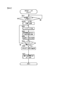
- FIG. 4 is a flowchart showing the operation of the in-vehicle processing device 120 in the recording phase.
- the execution subject of each step described below is the calculation unit 121 of the in-vehicle processing device 120.
- the calculation unit 121 functions as the point cloud data acquisition unit 121A when performing the processing illustrated in FIG.
- step S501 it is determined whether the recording start button 110A has been pressed. If it is determined that the recording start button 110A has been pressed, the process proceeds to step S501A, and if it is determined that the recording start button 110A has not been pressed, the process remains at step S501.
- step S501A a new recording area is secured in the RAM 122. In this storage area, the extracted point cloud and the travel route of the vehicle 1 are recorded in the coordinates of the local coordinate system described above.
- step S502 information is acquired from the sensor group and the above-mentioned landmark positioning is performed, that is, the point group forming the landmark using the image captured by the camera 102 is extracted.
- step S503 the moving amount of the vehicle 1 during the time from the last photographing by the camera 102 to the latest photographing is estimated, and the current position of the vehicle 1 recorded in the RAM 122 is updated.
- step S503 since the history of the coordinates of the movement of the vehicle 1 is finally recorded as the travel route, in step S503, the current position is not actually overwritten, but new position information is recorded while the previous position information is left. To do.
- the movement amount of the vehicle 1 can be estimated by a plurality of means. For example, as described above, the movement amount of the vehicle 1 can be estimated from the change in the position of the subject existing on the road surface in the image captured by the camera 102. If a high-accuracy GPS receiver with a small error is installed as the GPS receiver 107, the output thereof may be used. Then, the process proceeds to step S504.
- step S504 the point cloud extracted in step S502 is stored in the RAM 122 as coordinates in the local coordinate system based on the current position updated in step S503.
- step S505 it is determined whether or not the recording completion button 110B is pressed. If it is determined that the recording completion button 110B is pressed, the process proceeds to step S506, and if it is determined that the recording completion button 110B is not pressed. It returns to step S502.
- step S506 the current latitude and longitude of the vehicle 1 is acquired from the GPS receiver 107, and the parking position, that is, the current position of the vehicle 1 and the coordinates of the four corners of the vehicle 1 in the local coordinate system are recorded. Then, the process proceeds to step S507.
- step S506 it is determined whether or not the parking lot data having the latitude/longitude substantially matching the current latitude/longitude of the vehicle 1 acquired in step S505A is recorded in the parking lot point group 124A. If it is determined that the current latitude/longitude of the vehicle 1 is substantially the same as the latitude/longitude of any parking lot data recorded in the parking lot point group 124A, the process proceeds to step S507, and if not, the process proceeds to step S510. In step S510, the point cloud data stored in the RAM 122, the latitude and longitude of the vehicle 1 recorded in step S505A, and the parking position are recorded in the parking lot point cloud 124A as new parking lot data. This is the end of the flowchart of FIG.
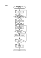
- FIG. 5 is a flowchart showing the overall operation of the in-vehicle processing device 120 in the automatic parking phase.
- the execution subject of each step described below is the calculation unit 121 of the in-vehicle processing device 120.
- the on-vehicle processor 120 first measures the current latitude and longitude using the GPS receiver 107 (step S601), and the latitude and longitude substantially match the latitude and longitude of any parking lot data of the parking lot point cloud 124A. Or not. In other words, it is determined whether or not there is a parking lot within a predetermined distance from the position of the vehicle 1 (step S602). When it is determined that the latitude/longitude of any parking lot data and the latitude/longitude of the vehicle 1 substantially match, the process proceeds to step S603, and when it is determined that the latitude/longitude of any parking lot data does not substantially match, the process returns to step S601. When returning to step S601, there is a possibility that an affirmative determination is made in step S602 due to the movement of the vehicle 1 by the driving of the user.
- the in-vehicle processing device 120 identifies the parking lot data having the latitude and longitude that substantially match the current position of the vehicle 1 from the plurality of parking lot data included in the parking lot point group 124A (step S603).
- the on-vehicle processor 120 initializes the local peripheral information 122A stored in the RAM 122 and the current position of the vehicle 1 stored in the RAM 122 as an initialization process. Specifically, if the previous information is recorded, it is erased and a new coordinate system is set. In the present embodiment, as described above, this coordinate system is called "local coordinate system". This local coordinate system is set based on the position and orientation of the vehicle 1 when step S603A is executed.
- the position of the vehicle 1 when step S603A is executed is set as the origin of the local coordinate system, and the X axis and the Y axis are set according to the orientation when step S603A is executed. Further, in the initialization of the current position of the vehicle 1, the current position of the vehicle 1 is set to the origin (0,0).
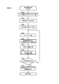
- the in-vehicle processor 120 estimates the self-position according to the procedure shown in FIG. 6, that is, estimates the position of the vehicle 1 in the parking lot coordinate system (step S604), and determines whether the self-position can be estimated in step S605. ..
- the in-vehicle processing device 120 proceeds to step S606 when determining that the estimation is possible, and returns to step S604 when determining that the estimation cannot be performed.
- step S606 the in-vehicle processing device 120 displays on the display device 111 that automatic parking is possible, and in subsequent step S607, it is determined whether or not the user has pressed the automatic parking button 110C.
- the processing proceeds to step S608, the automatic parking process is executed according to the procedure shown in FIG. 7, and when it is determined that the automatic parking button 110C has not been pressed, It returns to step S606.
- FIG. 6 is a flowchart showing details of the self-position estimation process.
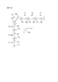
- 7 to 8 are image diagrams showing an outline of the self-position estimation processing.
- the arithmetic unit 121 functions as the local peripheral information creation unit 121B when performing the processing shown in steps S623 to S625 of FIG.
- step S620 the in-vehicle processing device 120 reads the travel route of the vehicle 1 included in the parking lot point group 124A specified in step S603 of FIG. 5, and divides it into N pieces in the distance direction.
- region which divided the traveling route is called a "section.”
- the travel route is a single locus in which one vehicle 1 travels from the entrance of the parking lot to the parking position, and thus can be divided into any number.
- the division is preferably divided into equal parts, but it is not always necessary to divide the parts into equal parts.
- the division number N is a prescribed value of 2 or more. In the example shown in FIG. 7, the number of divisions N is “7”, and the travel route T is divided into seven. As a result, in the example shown in FIG. 7, it is divided into seven sections from the first section T1 to the seventh section T7.
- step S621 the in-vehicle processing device 120 reads the parking area included in the parking lot point group 124A specified in step S603 of FIG. 5, and specifies the traveling direction in which the vehicle 1 is about to travel.
- the vehicle 1 is heading to the parking area, and therefore, in step S621, it is specifically determined that the vehicle travels in the direction from the end farther from the parking area to the end closer to the parking area among both ends of the travel route. ..
- the travel route T read in step S620 and the parking area 903 read in step S621 are shown.
- both ends of the traveling route T are defined as a first end 403 and a second end 404.
- the vehicle 1 travels in the traveling direction from the second end 404 to the first end 403. Identified as direction 402.
- step S622 the in-vehicle processor 120 specifies the initial position and the initial direction of the vehicle 1 in each section, and proceeds to step S623.
- the position and direction specified here are not the current vehicle 1 that is executing the automatic parking phase, but the past vehicle 1 that has been executing the recording phase.
- the initial position is the end of each section on the side opposite to the traveling direction.
- the initial direction is the positional relationship between the positions of the vehicle 1 forming the travel route read in step S620, and is determined by the positional relationship between the initial position and its front, the initial position and its rear, or the initial position and its front and rear. It
- the initial position and initial direction will be explained using the second section T2 in FIG. 8 as an example.
- Both ends of the second section T2 are positions 410 and 420. Of these two ends, the end opposite to the traveling direction 402, that is, the position of reference numeral 410 is the initial position. If the traveling direction is opposite, the initial position of the second section T2 is the position 420.
- An enlarged view of the vicinity of the position of reference numeral 410 is shown in the center of FIG.
- the positions of the vehicle 1 constituting the travel route read in step S620 are present in the order of reference numeral 409, reference numeral 410, reference numeral 411, and reference numeral 412 in the traveling direction 402.
- the initial direction may be the direction of the arrow 421 from the reference numeral 409 to the reference numeral 410, the direction of the arrow 422 from the reference numeral 410 to the reference numeral 411, or the direction obtained by combining the arrows 421 and 422. But it's okay. Note that the combination of two arrows is a direction obtained by treating each arrow as a vector and combining the vectors. Returning to the flowchart shown in FIG. 6, the description will be continued.
- steps S623 to S625 are executed.
- the landmark positioning in step S623, the estimation of the amount of movement of the vehicle in step S624, and the recording of the local peripheral information 122A in step S625 are substantially the same as the processing in steps S502 to S504 in FIG. The difference is that the data stored in the RAM 122 is recorded as the local peripheral information 122A.
- the in-vehicle processor 120 evaluates the degree of coincidence for each section, the details of which are shown in FIG. 9 (step S626).
- step S627 the in-vehicle processor 120 determines whether or not there is only one section whose matching degree does not decrease as a result of the evaluation in step S626, that is, the matching degree is constant or the matching degree increases even if the vehicle 1 moves. It is determined whether there is only one section to be executed.
- the in-vehicle processor 120 proceeds to step S628 when making an affirmative decision, and returns to step S623 when making a negative decision.
- step S628 the in-vehicle processing device 120 adopts the position information in the section for which an affirmative determination is made in step S627, and ends the processing shown in FIG.
- the in-vehicle processor 120 makes an affirmative decision in step S627 even when there are a plurality of sections for which the degree of coincidence does not decrease in step S626, and in step S628 the position information of the section with the highest degree of coincidence is adopted. May be.
- FIG. 9 is a flowchart showing details of the process of evaluating the degree of coincidence for each section.
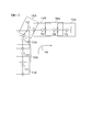
- 10 to 11 are image diagrams showing an outline of the evaluation of the degree of coincidence.
- 10 to 11 are the same scenes as the examples of FIGS. 7 and 8 shown above.
- FIG. 12 is a diagram showing the limitation of matching.
- the outline of the process shown in FIG. 9 is explained. Since the vehicle 1 always travels on the same route, it is assumed that the current position of the vehicle 1 at the time of starting the automatic parking phase is on the read traveling route. However, since it is impossible to immediately specify a specific position on the travel route, the following processing is performed. That is, the travel route recorded in the recording phase is divided into a plurality of sections, and the matching between the landmarks collected in the automatic parking phase and the recorded landmarks is evaluated in each section.
- the initial position and the initial direction in the parking lot coordinate system are calculated in advance using the parking lot point group 124A for each section. Then, it is assumed that the position and direction of the vehicle 1 at the time of starting the automatic parking phase match the calculated initial position and initial direction in each section.
- the virtual position of the vehicle 1 in the parking lot coordinate system is also referred to as “virtual point”. In this embodiment, there are as many virtual points as there are sections, and only one of them is very close to the actual position of the vehicle 1.
- the position of the virtual point and the virtual traveling direction of the vehicle 1 are updated.
- the position and orientation of the virtual point are updated, the landmarks around the virtual vehicle 1 in the parking lot coordinate system are read from the parking lot point group 124A, and the land actually acquired by the vehicle 1 in the automatic parking phase is read. Compare with mark.
- the landmark around the virtual vehicle 1 and the landmark actually acquired by the vehicle 1 in the automatic parking phase have a high matching rate. Show. In other sections, at least the matching rate between landmarks is low. Then, the detailed position of the vehicle 1 in the section in which the vehicle 1 is present is calculated and set as the current position of the vehicle 1. The processing of FIG. 9 will be described below.
- the in-vehicle processing device 120 executes the processing of each step sandwiched between step S640 and step S646 for each section.
- the in-vehicle processing device 120 sequentially changes the sections to be processed, and performs the processing from step S641 to step S645 for all the sections. These processes may be performed in order, or may be performed in parallel without waiting for the completion of the processes of other sections. The processing of each step from step S641 to step S645 will be described below.
- step S641 the in-vehicle processing device 120 calculates the difference between the position and traveling direction of the vehicle 1 at the start of the automatic parking phase and the current position and traveling direction of the vehicle 1, and acquires the movement amount and the direction change.
- the information obtained in step S641 is, for example, "1 m straight ahead, no direction change", "10 m in the initial direction, 3 m to the right, direction change +90 degrees”.
- step S642 the in-vehicle processing device 120 calculates the position and orientation of the virtual vehicle 1 in the parking lot coordinate system of the parking lot point group identified in step S603.
- the initial position and the initial direction in each section have been calculated in step S622, and the change amount from the initial state has been calculated in step S641. Therefore, in step S642, specifically, the sum of the calculation result of step S622 and the calculation result of step S641 is calculated.
- FIG. 10 is a diagram showing the position of the virtual vehicle 1 which is the processing result of step S642 when the calculation result of step S641 is only straight ahead for a predetermined distance.
- a code shown rearward in the traveling direction such as T11 or T21
- a code shown forward in the traveling direction such as T12 or T22
- vehicle-mounted processing device 120 extracts a landmark from the parking lot point cloud based on the position and traveling direction calculated in S642. For example, with the position calculated in S642 as the center and the traveling direction calculated in S642 as the front, a landmark included in a region having a first predetermined length in the width direction of the vehicle and a second predetermined length in the front-rear direction of the vehicle. To extract.
- FIG. 11 is a diagram showing an example of the processing result of step S643. However, FIG. 11 is based on the processing result shown in FIG. As shown in FIG. 11, in the first section T1, the landmarks included in the vertically elongated region T12A shown in the figure centered on the position T12 are extracted. Similarly, in the second section T2, landmarks included in the area T22A are extracted. However, the region T22A is illustrated as being slightly shifted to the right for convenience of illustration. In the third section T3, the initial traveling direction of the vehicle 1 is diagonally upward and there is no change in the traveling direction, so the region T42A for extracting the landmark is also inclined. In the fifth to seventh sections, the vehicle 1 faces the right direction in the drawing, so the landmarks are extracted from the horizontally long area. Returning to the flowchart, the explanation will be continued.
- step S644 the in-vehicle processing device 120 matches the landmark extracted in S634 with the local peripheral information.
- a known method such as ICP (Iterative Closest Point) can be used for this matching.
- step S644 translation and rotation are combined to search for the best match between the two, and the degree of match is evaluated as the degree of match. That is, as the calculation result of step S644, the position and the degree of coincidence of the vehicle 1 in the parking lot coordinate system when the vehicle 1 is present in the section to be processed are obtained.
- step S644 assuming that the vehicle 1 is moving on the previously recorded travel route, the rotation angle is limited (hereinafter also referred to as “angle limited comparison”), and the translational movement amount is set. It is desirable to set restrictions (hereinafter, also referred to as “movement limited comparison”). For example, in the angle limited comparison, the matching is performed only by rotating ⁇ 15 degrees, which is a total of positive and negative angles of 30 degrees.
- FIG. 12 is a diagram for explaining the angle limited comparison and the movement limited comparison.
- 12A is a conceptual diagram of landmarks in the local peripheral information 122A
- FIG. 12B is a conceptual diagram of landmarks extracted from the parking lot point cloud by the process of step S643.
- the arrow indicates the traveling direction of the vehicle 1
- the square frame indicates the range of the landmark. Note that in FIG. 12, since it is difficult to visually represent the difference between the position and the angle only by the arrow, only the square indicating the range of the landmark is displayed.
- the ranges of both landmarks are the same for the sake of convenience, but it is not essential that the two ranges are the same.
- FIGS. 12C to 12F Although examples of translation and rotation are shown in FIGS. 12C to 12F, here, for convenience, the position of the landmark in the local surrounding information 122A is fixed, and only the landmark extracted from the parking lot point group is used. Are moving.
- FIG. 12C is a conceptual diagram showing matching in which both the translational movement amount and the rotation angle are zero.
- the squares shown in FIGS. 12A and 12B are exactly overlapped with each other, and the traveling direction of the vehicle 1 at the virtual point and the traveling of the vehicle 1 when the local peripheral information is generated. The directions are the same and there is no translational movement.
- FIG. 12D is a conceptual diagram showing matching in which the rotation angle is zero and only the translational movement of the vehicle 1 in the traveling direction is not zero.
- the two arrows point in the same direction, so it can be seen that the rotation angle is zero, and since the positions of the two squares are displaced in the arrow direction, it can be seen that the translational movement is not zero. ..
- FIG. 12(e) is a conceptual diagram showing matching in which the translational movement is zero and the rotation angle is 20 degrees.
- FIG. 12F is a conceptual diagram showing matching in which the translational movement is zero and the rotation angle is 40 degrees.
- the state in which the rotation angle is 20 degrees shown in FIG. 12E is a state in which the rotation direction is 20 degrees from the angle at which the traveling direction of the vehicle 1 at the virtual point matches the traveling direction of the vehicle 1 when the local peripheral information is generated. Can also be said.
- the angle limited comparison matching is speeded up by setting a limit on the rotation angle. In this embodiment, since the angle is also estimated, it is expected that optimum matching can be obtained with a small rotation angle in the section where the vehicle 1 actually exists, so the angle limited comparison is effective.
- step S645 the in-vehicle processor 120 evaluates the matching result in step S644.
- the evaluation value of ICP may be used as it is, or evaluation may be performed by the number of feature points in which the distance between corresponding feature points is a predetermined value or less.
- the processing of steps S641 to S645 has been described above.
- the in-vehicle processing device 120 ends the processing in FIG. 9 after executing the processing in steps S641 to S645 for all sections.
- step S661 the position of the vehicle 1 in the parking lot coordinate system is estimated.
- step S662 a traveling route from the position estimated in step S661 to the parking position stored in the parking lot point group 124A is generated by a known route generation method. Then, the process proceeds to step S663.
- step S663 the steering device 131, the drive device 132, and the braking device 133 are controlled via the vehicle control device 130, and the vehicle 1 is moved to the parking position along the route generated in step S662.
- the operation command may be output to the drive device 132 only when the automatic parking button 110C is continuously pressed by the user.
- the braking device 133 is operated to stop the vehicle 1.
- step S664 the position of the vehicle 1 is estimated as in step S661.
- step S665 it is determined whether or not the parking is completed, that is, whether or not the vehicle 1 reaches the parking position, and when it is determined that the parking is not completed, the process returns to step S663 and it is determined that the parking is completed. If yes, the flowchart of FIG. 13 is terminated.
- the vehicle-mounted processing device 120 stores a parking lot point cloud 124A, which is point cloud data including a plurality of coordinates in a first coordinate system of a point representing a part of an object, that is, a parking lot coordinate system. 124, a sensor input unit that acquires the output of a sensor that acquires information around the vehicle 1, that is, an IF 125, and a movement information acquisition unit that acquires vehicle movement information that is information related to the movement of the vehicle 1, that is, an IF 125 and a sensor.
- a parking lot point cloud 124A which is point cloud data including a plurality of coordinates in a first coordinate system of a point representing a part of an object, that is, a parking lot coordinate system.
- 124 a sensor input unit that acquires the output of a sensor that acquires information around the vehicle 1, that is, an IF 125
- a movement information acquisition unit that acquires vehicle movement information that is information related to the movement of the vehicle 1, that is, an IF 125 and a sensor.
- the local peripheral information 122A including a plurality of coordinates of the position of the vehicle 1 in the second coordinate system, that is, the local coordinate system and the point representing a part of the object is generated.
- a local peripheral information creation unit 121B, a position estimation unit 121C that estimates the relationship between the parking lot coordinate system and the local coordinate system based on the parking lot point group 124A and the local peripheral information, and estimates the position of the vehicle in the parking lot coordinate system. Equipped with.
- the parking lot point group 124A includes the traveling route of the vehicle in the parking lot coordinate system.
- the position estimation unit 121C estimates the relationship between the parking lot coordinate system and the local coordinate system on the assumption that the vehicle 1 is traveling on the traveling route included in the parking lot point group 124A. Therefore, the position estimation unit 121C can narrow down the area of the parking lot coordinate system to be compared with the point group of the local coordinate system, so that the accuracy of position identification can be improved and the calculation speed can also be improved.
- the position estimating unit 121C sets a virtual point, which is a point moved based on the vehicle movement information, starting from any point on the travel route in the point cloud data.
- the relationship between the parking lot coordinate system and the local coordinate system is estimated by comparing the recorded feature points included in the area centered at with the local peripheral information. Therefore, the point clouds can be compared with each other after reflecting the movement of the vehicle 1 in the parking lot coordinate system.
- the position estimation unit 121C estimates the traveling direction of the vehicle 1 in the parking lot coordinate system using the plurality of coordinates included in the travel route, as described in step S622 of FIG.
- the position estimation unit 121C is included in a region centered on the virtual point at an angle within a predetermined range from an angle at which the traveling direction of the vehicle 1 at the virtual point and the traveling direction of the vehicle 1 when the local peripheral information is generated match.
- the recorded feature points are compared with local peripheral information.
- the position estimation unit 121C divides the travel route into a plurality of sections, and moves the virtual point in accordance with the movement of the vehicle 1 with the end of the travel route in the section as a starting point.
- the position estimation unit 121C selects one section from the plurality of sections based on the change in the result of the angle limited comparison due to the movement of the virtual point, and determines that the vehicle exists in the selected one section. Estimate the relationship between the parking lot coordinate system and the local coordinate system. Therefore, as described with reference to FIG. 12, the processing can be speeded up by limiting the matching rotation angle.
- the point cloud data includes the coordinates of the destination of the vehicle 1, that is, the parking area in the parking lot coordinate system.
- the position estimation unit 121C estimates the traveling direction of the vehicle on the traveling route as the direction approaching the coordinates of the destination. Therefore, even if the traveling direction of the vehicle 1 is not recorded in the recording phase, the traveling direction can be estimated by estimating the traveling direction of the vehicle 1.
- FIG. 14 is a diagram illustrating an example of the parking lot point group 124B in the first modification.
- information on the traveling direction of the vehicle 1 at each coordinate forming the traveling route may be recorded in the parking lot point group 124B.
- the traveling direction of the vehicle 1 is also recorded in step S504 of FIG.
- step S622 of FIG. 6 the traveling direction recorded from the parking lot point group 124B may be read.
- the point cloud data includes information on the traveling direction of the vehicle 1 when traveling on the traveling route.
- the position estimation unit 121C has an angle of a predetermined range from an angle at which the traveling direction of the vehicle at the virtual point and the traveling direction of the vehicle when the local peripheral information is generated coincide with each other, and is recorded in a region centered on the virtual point.
- Angle limited comparison which is a comparison between the feature points and the local peripheral information, is performed. Therefore, it is not necessary to calculate the traveling direction of the vehicle 1 at the time of recording, and the recorded accurate traveling direction can be used.
- Modification 2 In the evaluation of the degree of coincidence for each section illustrated in FIG. 9, it may be excluded from the candidates without performing detailed matching due to the deviation of the route. That is, when the distance between the position calculated in step S642 and the travel route T is equal to or greater than the predetermined distance, the degree of coincidence may be set to the minimum value, for example, zero without performing the calculation in steps S643 and S644. For example, in the fourth section T4 of FIG. 1, the position T42 is out of the travel route T, so the fourth section T4 does not have to execute steps S643 and S644.
- the virtual point is moved in synchronization with the movement amount and traveling direction of the vehicle 1 in the automatic parking phase.
- the virtual point may be moved in synchronization with only the movement amount of the vehicle 1.
- the calculation of the direction change is omitted in step S641 of FIG. 9, and only the position of the virtual point is calculated in step S642.
- the in-vehicle processing device 120 estimates the traveling direction of the vehicle 1 at the virtual point in the recording phase, and uses the traveling direction.
- the method of estimating the traveling direction of the vehicle 1 is as described in step S622 of FIG.
- FIG. 15 is a diagram showing the position of the virtual point, which is the processing result of step S642 when the calculation result of step S641 in Modification 3 is only a straight travel of a predetermined distance, and is a diagram in the first embodiment. Corresponds to 10.
- the virtual point T42 is out of the travel route T in the fourth section T4 where the travel route T is curved.
- the vehicle 1 since the vehicle 1 is only moved in the traveling direction based on the amount of movement of the vehicle 1, the virtual point always exists on the route T.
- the position estimating unit 121C compares the recorded feature points included in the area around the virtual point, which is any point on the travel route, of the point cloud data with the local surrounding information. Estimate the relationship between the parking lot coordinate system and the local coordinate system. Therefore, since it is necessary to move the virtual point in consideration of only the moving amount of the vehicle 1, the calculation can be simplified as compared with the first embodiment. Further, the effect of simplifying the calculation is hardly affected in the section in which the vehicle 1 is present, so there is little demerit.
- the calculation result of the fourth section T4 is greatly different from that of FIG. 10 of the first embodiment, but this is a calculation result for a section in which the vehicle 1 does not actually exist, so there is no problem. If the vehicle 1 is traveling in the fourth section T4, the virtual point should have been calculated on the route in FIG. 10 as well.
- step S626 is repeated for all sections. However, the calculation may be aborted halfway for sections with low degree of coincidence. For example, the calculation is stopped for a section whose degree of coincidence is lower than a predetermined threshold, and the calculation of step S626 is continued for the remaining sections.
- the vehicle 1 may be equipped with a sensor that acquires information around the vehicle 1, such as an ultrasonic sensor or a laser range finder. Further, it is not essential for the vehicle 1 to include a camera, and it is sufficient to include a sensor such as an ultrasonic sensor or a laser range finder that can measure a landmark.
- FIGS. 16 to 18 A second embodiment of the in-vehicle processing device will be described with reference to FIGS. 16 to 18.
- the same components as those of the first embodiment are designated by the same reference numerals, and the differences are mainly described.
- the points that are not particularly described are the same as those in the first embodiment.
- This embodiment differs from the first embodiment mainly in that the vehicle automatically travels from the parking position to the entrance of the parking lot.
- FIG. 16 is an overall configuration diagram of an automatic parking system 100A according to the second embodiment.
- the automatic parking system 100A according to the second embodiment focuses on the movement of the vehicle 1 out of the parking lot, and thus can be referred to as the leaving system 100A.
- 100 A of automatic parking systems are equipped with the portable terminal 2 and the base station 3 in addition to the structure in 1st Embodiment.
- the in-vehicle processing device 120A according to the second embodiment further includes a response unit 121D in the calculation unit 121, as compared with the in-vehicle processing device 120 according to the first embodiment.
- the mobile terminal 2 is a mobile communication terminal carried by the user, such as a mobile phone, a smartphone, or a tablet terminal.
- the mobile terminal 2 includes a communication unit 2A, a calling application 2B, and a user interface (not shown).
- the communication unit 2A is a communication module that can use a wireless communication service provided by a mobile communication carrier, and communicates with the in-vehicle processing device 120A via the base station 3.
- the calling application 2B is an application that can be operated using a CPU or the like built in the mobile terminal 2, and outputs a signal to the in-vehicle processing device 120A based on an operation by the user.
- the first signal is a signal summoning the vehicle 1 at the entrance of the parking lot
- the second signal is a signal stopping the vehicle 1.
- the calling application 2B outputs a first signal when it is activated and the button is pressed for the first time, and outputs a second signal when the button is pressed for the second time.
- the first signal may be output while the button is pressed
- the second signal may be output when the button is released.
- the base station 3 is a wireless communication facility installed by a mobile communication carrier for wireless communication service. Although only one base station 3 is shown in FIG. 16, a plurality of base stations 3 may exist and each base station 3 may be able to communicate with each other.
- the communication device 114 provided in the vehicle 1 communicates with the mobile terminal 2 via the base station 3 in the present embodiment.
- the communication device 114 receives the signal from the mobile terminal 2, the communication device 114 transmits the signal to the calculation unit 121 of the in-vehicle processing device 120A.
- the response unit 121D controls the vehicle 1 based on the signal transmitted from the communication device 114 as described later. Note that, hereinafter, the operation phase in which the response unit 121D operates will be referred to as the automatic shipping phase.
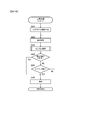
- FIG. 17 is a flowchart showing the processing of the automatic shipping phase by the response unit 121D.
- the execution subject of each step described below is the CPU of the in-vehicle processing device 120A.
- Responsive part 121D will start the process shown in FIG. 17, if a 1st signal is received.
- Part of the processing shown in FIG. 17 is the same as that of FIG. 5 in the first embodiment.
- the same processing is given the same step number and the description thereof is omitted.
- the processing from step S601 to step S603A is the same as that in FIG.
- step S603B the in-vehicle processor 120A starts moving at a slow speed.
- the slow speed starting in this step continues until step S680 is executed.
- the in-vehicle processing device 120 appropriately operates the steering angle using the positional relationship between the parking area and the travel route recorded in the parking lot point group 124A.
- the vehicle turns to the left as soon as it leaves the parking area.
- the possibility of contacting an obstacle such as a parked vehicle is higher than usual. Therefore, not only the information obtained from the camera 102 but also other sensors such as an ultrasonic sensor and a laser range finder in the vehicle 1 can be used to avoid obstacles by using the information obtained from them. desirable.
- step S604 the in-vehicle processor 120A starts self-position estimation.
- the self-position estimation method is almost the same as that of the first embodiment, but the difference will be described later.
- step S604 the in-vehicle processor 120A executes step S605. If an affirmative decision is made, the operation proceeds to step S680 to start automatic warehousing, and if a negative decision is made, the operation returns to step S604. The automatic shipping process will be described later.
- the traveling direction of the vehicle 1 is different between the first embodiment and the second embodiment. Therefore, in the second embodiment, the direction specified in step S621 is opposite to that in the first embodiment.
- the on-vehicle processing device 120 determines that the vehicle travels in the direction from the end farther to the parking area to the end closer to the parking area among both ends of the travel route.
- the on-vehicle processing device 120A determines that the vehicle travels in the direction from the end near the parking area to the end far from the parking area among both ends of the travel route.
- step S623 Since the traveling direction specified in step S621 is different, the initial position and initial direction in step S622 are also changed accordingly.
- the processing after step S623 is similar to that of the first embodiment.
- the process of FIG. 9 showing the details of step S626 is also the same as that of the first embodiment.
- FIG. 18 is a flowchart showing details of step S680 in FIG.
- the in-vehicle processing device 120A generates a route from the parking area to the coordinates of the far end of the entrance of the parking lot, that is, the end of the recorded travel route.
- vehicle-mounted processing device 120A controls vehicle 1 so as to follow the route generated in step S681.
- in-vehicle processing device 120A performs self-position estimation.
- step S684 the in-vehicle processor 120A determines whether or not the second signal has been received. If the in-vehicle processing device 120A determines that the second signal has been received, the process proceeds to step S686, and if it determines that the second signal has not been received, the process proceeds to step S685. In step S685, the in-vehicle processing device 120A determines whether or not the vehicle 1 has reached the entrance, proceeds to step S686 if it is determined that the vehicle 1 has arrived, and proceeds to step S682 if it determines that the vehicle 1 has not arrived. Return to. In step S686, the in-vehicle processing device 120A stops the vehicle 1 and ends the processing shown in FIG.
- the exit system 100A includes an in-vehicle processing device 120A mounted on the vehicle 1 and a mobile terminal 2 that communicates with the in-vehicle processing device 120A.
- the mobile terminal 2 includes a communication unit 2A that outputs the first signal to the in-vehicle processing device 120A.
- the on-vehicle processor 120A includes a storage unit 124 that stores a parking lot point cloud 124A, which is point cloud data including a plurality of coordinates in a first coordinate system of a point that represents a part of an object, that is, a parking lot coordinate system.
- a sensor input unit that acquires an output of a sensor that acquires information around the vehicle 1, that is, an IF 125, and a movement information acquisition unit that acquires vehicle movement information that is information regarding the movement of the vehicle 1, that is, an IF 125 and a sensor input unit.
- the local peripheral information 122A including a plurality of coordinates in the second coordinate system, that is, the position of the vehicle 1 in the local coordinate system and the point representing a part of the object in the local coordinate system is generated.
- a local surrounding information creating unit 121B a position estimating unit 121C that estimates the relationship between the parking lot coordinate system and the local coordinate system based on the parking lot point group 124A and the local surrounding information, and estimates the position of the vehicle in the parking lot coordinate system.
- the parking lot point group 124A includes the traveling route of the vehicle 1 and the starting position of the vehicle 1, that is, the parking area in the parking lot coordinate system.
- the position estimation unit 121C estimates the relationship between the parking lot coordinate system and the local coordinate system on the assumption that the vehicle 1 is traveling on the traveling route included in the parking lot point group 124A.
- the in-vehicle processing device 120A estimates the position of the vehicle in the parking lot coordinate system using the position estimation unit 121C, outputs an operation command to the vehicle control device 130, and moves away from the starting position.
- a response unit 121D that drives the vehicle along the travel route is provided. Therefore, the vehicle 1 parked at the parking position can be summoned to the entrance of the parking lot.
- the communication unit 2A of the mobile terminal 2 can further output the second signal.
- Responsive part 121D of in-vehicle processor 120A will stop a vehicle, if a 2nd signal is received. Therefore, the user can stop the vehicle 1 at any position.
- the response unit 121D may receive the position information from the mobile terminal 2 and stop the vehicle 1 when the position of the in-vehicle processing device 120A is within a predetermined distance from the position indicated by the received position information.
- FIG. 19 is an overall configuration diagram of an automatic parking system 100B according to the first modification of the second embodiment. This modification is different from the configuration of the second embodiment in that the mobile terminal 2 includes a mobile position estimating unit 2C. The operation of the calling application 2B of the mobile terminal 2 and the operation of the response unit 121D of the in-vehicle processing device 120A are different from those of the second embodiment.
- the mobile position estimating unit 2C receives signals from a plurality of satellites that form the satellite navigation system, and calculates the position of the GPS receiver 107 in the geodetic system, that is, the latitude and longitude by calculation based on the received signals. Note that, hereinafter, the position in the geodetic system calculated by the mobile position estimation unit 2C is also referred to as a "mobile position”. The “calculation” of the mobile position by the mobile position estimation unit 2C is also referred to as “estimation” of the mobile position.
- the mobile position estimation unit 2C may receive a position correction signal via the communication unit 2A and use the correction signal to improve the mobile position estimation accuracy.
- the mobile position estimating unit 2C may further include a wireless LAN communication module, and improve the mobile position estimation accuracy by using a correction signal obtained via the wireless LAN.
- the calling application 2B transmits the mobile position estimated by the mobile position estimating unit 2C to the in-vehicle processing device 120A.
- the transmission of the mobile position by the calling application 2B may be transmitted only once together with the transmission of the first signal, or may be repeatedly transmitted at predetermined time intervals, for example, every 10 seconds or 1 minute.
- the portable position estimating unit 2C may estimate the portable position each time and transmit the newly estimated portable position. desirable.
- FIG. 20 is a flowchart showing details of step S680 of FIG. 17 in this modification. That is, FIG. 20 corresponds to FIG. 18 in the second embodiment. In FIG. 20, step S684A is added after step S684 in FIG. The differences from FIG. 18 will be described below.
- the in-vehicle processing device 120A proceeds to step S686 when making a positive determination in step S684, but proceeds to step S684A when making a negative determination in step S684.
- step S684A the in-vehicle processing device 120A determines whether or not the distance between the vehicle position calculated by the GPS receiver 107 and the mobile position received from the mobile terminal 2 is within a predetermined distance, for example, within 3 m.
- the on-vehicle processing device 120A proceeds to step S686 when determining that the distance between the two positions is within the predetermined distance, and proceeds to step S685 when determining that the distance between the two positions is longer than the predetermined distance. Since the subsequent processing is the same as that of the second embodiment, the description thereof will be omitted.
- the mobile terminal 2 includes a mobile position estimation unit 2C that estimates the mobile position, which is the position of the mobile terminal 2 in the geodetic system.
- the communication unit 2A of the mobile terminal 2 can output the mobile position.
- the interface 125 of the in-vehicle processing device 120A acquires the vehicle position from the GPS receiver 107 that estimates the vehicle position, which is the position of the vehicle 1 in the geodetic system.
- the response unit 121D of the in-vehicle processing device 120A stops the vehicle when the difference between the mobile position received from the mobile terminal 2 and the vehicle position is within a predetermined distance. Therefore, even if there is no explicit stop command from the user, the vehicle 1 can be stopped near the user who owns the mobile terminal 2.
- the mobile terminal 2 may not be able to output the second signal.
- the in-vehicle processing device 120A proceeds to step S684A upon completion of the process of step S683 in the flowchart shown in FIG.
- the program executed by the in-vehicle processing device 120 is stored in the ROM 123 (not shown), but the program may be stored in the storage unit 124. Further, the in-vehicle processing device 120 may include an input/output interface (not shown), and the program may be read from another device via the input/output interface and a medium that can be used by the in-vehicle processing device 120 when necessary.
- the medium refers to, for example, a storage medium that can be attached to and detached from the input/output interface, or a communication medium, that is, a wired, wireless, optical, or other network, or a carrier wave or digital signal that propagates through the network.
- some or all of the functions realized by the program may be realized by a hardware circuit or FPGA.
- Vehicle 2 ... Portable terminal 2A... Communication part 2C... Portable position estimation part 100, 100A, 100B... Automatic parking system 102... Camera 107... GPS receiver 108... Vehicle speed sensor 109... Steering angle sensor 120... In-vehicle processing device 121... Calculation part 121A... Point cloud data acquisition part 121B... Local peripheral information creation part 121C... Position estimation part 121D... Response part 122A... Local peripheral information 124... Storage part 124A... Parking lot point cloud 125... Interface 130... Vehicle control device
Landscapes
- Engineering & Computer Science (AREA)
- Radar, Positioning & Navigation (AREA)
- Remote Sensing (AREA)
- Automation & Control Theory (AREA)
- Transportation (AREA)
- Mechanical Engineering (AREA)
- Physics & Mathematics (AREA)
- General Physics & Mathematics (AREA)
- Navigation (AREA)
- Control Of Driving Devices And Active Controlling Of Vehicle (AREA)
- Traffic Control Systems (AREA)
Abstract
車載処理装置は、物体の一部を表す点の第1座標系における複数の座標が含まれる点群データが格納される記憶部と、車両の周囲の情報を取得するセンサの出力を取得するセンサ入力部と、車両の移動に関する情報である車両移動情報を取得する移動情報取得部と、センサ入力部、および移動情報取得部が取得する情報に基づき、第2座標系における車両の位置および物体の一部を表す点の第2座標系における座標が複数含まれる局所周辺情報を生成する局所周辺情報作成部と、点群データと局所周辺情報とに基づき第1座標系と第2座標系の関係を推定し、第1座標系における車両の位置を推定する位置推定部とを備え、点群データには、第1座標系における車両の走行経路が含まれ、位置推定部は、車両が点群データに含まれる走行経路を走行していることを前提として第1座標系と第2座標系の関係を推定する。
Description
本発明は、車載処理装置、位置推定方法、および出庫システムに関する。
近年、自動車の自動運転実現に向けた活動が盛んとなっている。自動運転とは、車両周囲をカメラや超音波レーダ、レーダなどの外界センサでセンシングし、センシング結果に基づいて判断を行い、ユーザの操作なしで車両が自律的に走行するものである。この自動運転には車両の位置推定が必要となる。特許文献1には物体の一部を表す点の第1座標系における座標が複数含まれる点群データが格納される記憶部と、車両の周囲の情報を取得するセンサの出力を取得するセンサ入力部と、前記車両の移動に関する情報を取得する移動情報取得部と、前記センサ入力部、および前記移動情報取得部が取得する情報に基づき、第2座標系における前記車両の位置および物体の一部を表す点の前記第2座標系における座標が複数含まれる局所周辺情報を生成する局所周辺情報作成部と、前記点群データと前記局所周辺情報とに基づき前記第1座標系と前記第2座標系の関係を推定し、前記第1座標系における前記車両の位置を推定する位置推定部とを備える車載処理装置が開示されている。
位置特定の精度向上および演算時間の短縮が望ましい。
本発明の第1の態様による車載処理装置は、物体の一部を表す点の第1座標系における複数の座標が含まれる点群データが格納される記憶部と、車両の周囲の情報を取得するセンサの出力を取得するセンサ入力部と、前記車両の移動に関する情報である車両移動情報を取得する移動情報取得部と、前記センサ入力部、および前記移動情報取得部が取得する情報に基づき、第2座標系における前記車両の位置および物体の一部を表す点の前記第2座標系における座標が複数含まれる局所周辺情報を生成する局所周辺情報作成部と、前記点群データと前記局所周辺情報とに基づき前記第1座標系と前記第2座標系の関係を推定し、前記第1座標系における前記車両の位置を推定する位置推定部とを備え、前記点群データには、前記第1座標系における前記車両の走行経路が含まれ、前記位置推定部は、前記車両が前記点群データに含まれる走行経路を走行していることを前提として前記第1座標系と前記第2座標系の関係を推定する。
本発明の第2の態様による位置推定方法は、物体の一部を表す点の第1座標系における複数の座標が含まれる点群データが格納される記憶部、車両の周囲の情報を取得するセンサの出力を取得するセンサ入力部、および前記車両の移動に関する情報である車両移動情報を取得する移動情報取得部を備える前記車両に備えられる車載処理装置が実行する位置推定方法であって、前記センサ入力部、および前記移動情報取得部が取得する情報に基づき、第2座標系における前記車両の位置および物体の一部を表す点の前記第2座標系における座標が複数含まれる局所周辺情報を生成することと、前記点群データと前記局所周辺情報とに基づき前記第1座標系と前記第2座標系の関係を推定し、前記第1座標系における前記車両の位置を推定することと、前記点群データには、前記第1座標系における前記車両の走行経路が含まれ、前記車両が前記点群データに含まれる走行経路を走行していることを前提として前記第1座標系と前記第2座標系の関係を推定することとを含む。
本発明の第3の態様による出庫システムは、車両に搭載される車載処理装置、および前記車載処理装置と通信する携帯端末を備える出庫システムであって、前記携帯端末は、前記車載処理装置に第1の信号を出力する通信部を備え、前記車載処理装置は、物体の一部を表す点の第1座標系における複数の座標が含まれる点群データが格納される記憶部と、車両の周囲の情報を取得するセンサの出力を取得するセンサ入力部と、前記車両の移動に関する情報である車両移動情報を取得する移動情報取得部と、前記センサ入力部、および前記移動情報取得部が取得する情報に基づき、第2座標系における前記車両の位置および物体の一部を表す点の前記第2座標系における座標が複数含まれる局所周辺情報を生成する局所周辺情報作成部と、前記点群データと前記局所周辺情報とに基づき前記第1座標系と前記第2座標系の関係を推定し、前記第1座標系における前記車両の位置を推定する位置推定部とを備え、前記点群データには、前記第1座標系における前記車両の走行経路、および前記第1座標系における前記車両の始動位置が含まれ、前記位置推定部は、前記車両が前記点群データに含まれる走行経路を走行していることを前提として前記第1座標系と前記第2座標系の関係を推定し、前記車載処理装置はさらに、前記第1の信号を受信すると、前記位置推定部を用いて前記第1座標系における前記車両の位置を推定し、前記始動位置から遠ざかる方向に前記走行経路に沿って前記車両を走行させる応答部を備える。
本発明の第2の態様による位置推定方法は、物体の一部を表す点の第1座標系における複数の座標が含まれる点群データが格納される記憶部、車両の周囲の情報を取得するセンサの出力を取得するセンサ入力部、および前記車両の移動に関する情報である車両移動情報を取得する移動情報取得部を備える前記車両に備えられる車載処理装置が実行する位置推定方法であって、前記センサ入力部、および前記移動情報取得部が取得する情報に基づき、第2座標系における前記車両の位置および物体の一部を表す点の前記第2座標系における座標が複数含まれる局所周辺情報を生成することと、前記点群データと前記局所周辺情報とに基づき前記第1座標系と前記第2座標系の関係を推定し、前記第1座標系における前記車両の位置を推定することと、前記点群データには、前記第1座標系における前記車両の走行経路が含まれ、前記車両が前記点群データに含まれる走行経路を走行していることを前提として前記第1座標系と前記第2座標系の関係を推定することとを含む。
本発明の第3の態様による出庫システムは、車両に搭載される車載処理装置、および前記車載処理装置と通信する携帯端末を備える出庫システムであって、前記携帯端末は、前記車載処理装置に第1の信号を出力する通信部を備え、前記車載処理装置は、物体の一部を表す点の第1座標系における複数の座標が含まれる点群データが格納される記憶部と、車両の周囲の情報を取得するセンサの出力を取得するセンサ入力部と、前記車両の移動に関する情報である車両移動情報を取得する移動情報取得部と、前記センサ入力部、および前記移動情報取得部が取得する情報に基づき、第2座標系における前記車両の位置および物体の一部を表す点の前記第2座標系における座標が複数含まれる局所周辺情報を生成する局所周辺情報作成部と、前記点群データと前記局所周辺情報とに基づき前記第1座標系と前記第2座標系の関係を推定し、前記第1座標系における前記車両の位置を推定する位置推定部とを備え、前記点群データには、前記第1座標系における前記車両の走行経路、および前記第1座標系における前記車両の始動位置が含まれ、前記位置推定部は、前記車両が前記点群データに含まれる走行経路を走行していることを前提として前記第1座標系と前記第2座標系の関係を推定し、前記車載処理装置はさらに、前記第1の信号を受信すると、前記位置推定部を用いて前記第1座標系における前記車両の位置を推定し、前記始動位置から遠ざかる方向に前記走行経路に沿って前記車両を走行させる応答部を備える。
本発明によれば、位置特定の精度の向上および演算時間の短縮ができる。
―第1の実施の形態―
以下、図1~図13を参照して、本発明にかかる車載処理装置の第1の実施の形態を説明する。
以下、図1~図13を参照して、本発明にかかる車載処理装置の第1の実施の形態を説明する。
図1は、本発明にかかる車載処理装置を含む自動駐車システム100の構成図である。自動駐車システム100は、車両1に搭載される。自動駐車システム100は、センサ群102、107~109と、入出力装置群110、111、114と、車両1を制御する制御装置群130~133と、車載処理装置120とから構成される。センサ群、入出力装置群、および制御装置群は車載処理装置120と信号線で接続され、車載処理装置120と各種データを授受する。以下では、車両1に乗車する人間を「ユーザ」と呼ぶ。
車載処理装置120は、演算部121と、RAM122と、ROM123と、記憶部124と、インタフェース125とを備える。車載処理装置120はたとえばECU(Electronic Control Unit;電子制御装置)である。演算部121はCPUである。FPGAなど他の演算処理装置で全部または一部の演算処理を実行するように構成してもよい。RAM122は読み書き込み可能な記憶領域であり、車載処理装置120の主記憶装置として動作する。RAM122には、後述する局所周辺情報122Aが格納される。ROM123は読み取り専用の記憶領域であり、後述するプログラムが格納される。このプログラムはRAM122で展開されて演算部121により実行される。演算部121は、プログラムを読み込んで実行することにより、点群データ取得部121A、局所周辺情報作成部121B、および位置推定部121Cとして動作する。
記憶部124は不揮発性の記憶装置であり、車載処理装置120の補助記憶装置として動作する。記憶部124には、駐車場点群124Aが格納される。駐車場点群124Aとは、1または複数の駐車場データである。駐車場データとは、ある駐車場の位置情報、すなわち緯度・経度、駐車領域を示す座標、およびその駐車場に存在するランドマークを構成する点の座標の集合である。ランドマークについては後述する。インタフェース125は、車載処理装置120と自動駐車システム100を構成する他の機器との情報の授受を行う。インタフェース125は、車両1の周囲の情報を取得するカメラ102の出力を取得するので、センサ入力部とも呼べる。またインタフェース125は、車速センサ108および舵角センサ109から車両1の移動に関する情報を取得するので、移動情報取得部とも呼べる。
センサ群は、車両1の周囲を撮影するカメラ102と、GPS受信機107と、車速センサ108と、舵角センサ109とを含む。
カメラ102は、撮影して得られた画像(以下、撮影画像)を車載処理装置120に出力する。車載処理装置120は、カメラ102の撮影画像を用いて後述するランドマークの測位を行う。カメラ102の焦点距離や撮像素子サイズなどの内部パラメータ、および車両1へのカメラ102の取り付け位置や取り付け姿勢である外部パラメータは既知であり、ROM123にあらかじめ保存されている。車載処理装置120は、ROM123に格納された内部パラメータおよび外部パラメータを用いて、被写体とカメラ102との位置関係を算出することができる。
GPS受信機107は、衛星航法システムを構成する複数の衛星から信号を受信し、受信した信号に基づく演算によりGPS受信機107の測地系における位置、すなわち緯度および経度を算出する。なおGPS受信機107により算出される緯度および経度の精度は高精度でなくてもよく、たとえば数m~10m程度の誤差が含まれてもよい。GPS受信機107は、算出した緯度および経度を車載処理装置120に出力する。
車速センサ108、および舵角センサ109はそれぞれ、車両1の車速と舵角を測定し車載処理装置120に出力する。車載処理装置120は、車速センサ108および舵角センサ109の出力を用いて公知のデッドレコニング技術によって、車両1の移動量および移動方向を算出する。
入力装置110には、ユーザによる車載処理装置120への動作指令が入力される。入力装置110は、記録開始ボタン110Aと、記録完了ボタン110Bと、自動駐車ボタン110Cとを含む。表示装置111はたとえば液晶ディスプレイであり、車載処理装置120から出力される情報が表示される。なお、入力装置110と表示装置111とが一体として、たとえばタッチ操作に対応する液晶ディスプレイとして構成されてもよい。この場合は、液晶ディスプレイの所定の領域がタッチされることにより、記録開始ボタン110A、記録完了ボタン110B、または自動駐車ボタン110Cが押されたと判断してもよい。
通信装置114は、車両1の外部の機器と車載処理装置120とが無線で情報を授受するために用いられる。例えば、ユーザが車両1の外にいるときに、ユーザが身に着けている携帯端末と通信を行い情報を授受する。通信装置114が通信を行う対象はユーザの携帯端末に限定されない。
車両制御装置130は、車載処理装置120の動作指令に基づき、操舵装置131、駆動装置132、および制動装置133を制御する。操舵装置131は、車両1のステアリングを操作する。駆動装置132は、車両1に駆動力を与える。駆動装置132はたとえば、車両1が備えるエンジンの目標回転数を増加させることにより車両1の駆動力を増加させる。制動装置133は、車両1に制動力を与える。
(ランドマーク測位)
ランドマークとはセンサにより識別可能な特徴を有する物体であり、たとえば路面ペイントの1種である駐車枠線や、車両の走行の妨げとなる障害物である建物の壁などである。本実施の形態では、移動体である車両や人間はランドマークに含めない。車載処理装置120は、カメラ102から入力される情報に基づき、車両1の周辺に存在するランドマーク、すなわちセンサにより識別可能な特徴を有する点を検出する。以下では、外界センサ、すなわちカメラ102から入力される情報に基づくランドマークの検出を「ランドマーク測位」と呼ぶ。
ランドマークとはセンサにより識別可能な特徴を有する物体であり、たとえば路面ペイントの1種である駐車枠線や、車両の走行の妨げとなる障害物である建物の壁などである。本実施の形態では、移動体である車両や人間はランドマークに含めない。車載処理装置120は、カメラ102から入力される情報に基づき、車両1の周辺に存在するランドマーク、すなわちセンサにより識別可能な特徴を有する点を検出する。以下では、外界センサ、すなわちカメラ102から入力される情報に基づくランドマークの検出を「ランドマーク測位」と呼ぶ。
車載処理装置120は、カメラ102の撮影画像を対象に、以下のように画像認識プログラムを動作させることで駐車枠などの路面ペイントなどを検出する。駐車枠の検出は、まず入力画像からソーベルフィルタなどでエッジを抽出する。次に、たとえば白から黒への変化であるエッジの立ち上がりと、黒から白への変化であるエッジの立ち下がりのペアを抽出する。そしてこのペアの間隔が、あらかじめ定めた第1の所定の距離、すなわち駐車枠を構成する白線の太さと略一致すると、このペアを駐車枠の候補とする。同様の処理により駐車枠の候補を複数検出し、駐車枠の候補同士の間隔があらかじめ定めた第2の所定の距離、すなわち駐車枠の白線の間隔と略一致すると、それらを駐車枠として検出する。駐車枠以外の路面ペイントは以下の処理を実行する画像認識プログラムで検出される。まず入力画像からソーベルフィルタなどでエッジを抽出する。エッジ強度があらかじめ定めた一定の値よりも大きく、エッジ同士の間隔が白線の幅に相当するあらかじめ定めた距離である画素を探索することにより検出できる。
車載処理装置120はたとえば既知のテンプレートマッチングにより車両や人間を検出し、測定結果から除外する。また、以下のようにして検出した移動体を測定結果から除外してもよい。すなわち車載処理装置120は、内部パラメータおよび外部パラメータを用いて撮影画像における被写体とカメラ102との位置関係を算出する。次に車載処理装置120は、カメラ102が連続して取得した撮影画像において被写体を追跡することで車両1と被写体の相対的な速度を算出する。最後に車載処理装置120は、車速センサ108および舵角センサ109の出力を用いて車両1の速度を算出し、被写体との相対的な速度と一致しなければ被写体が移動体であると判断し、この移動体に関する情報を測定結果から除外する。
(駐車場点群124A)
図2は、記憶部124に格納される駐車場点群124Aの一例を示す図である。図2では、駐車場点群124Aとして2つの駐車場データが格納されている例を示している。1つの駐車場データは、その駐車場の位置、すなわち緯度および経度(以下、緯度経度と呼ぶ)と、駐車領域の座標と、車両1の走行経路と、ランドマークを構成する点の二次元平面上の座標とから構成される。
図2は、記憶部124に格納される駐車場点群124Aの一例を示す図である。図2では、駐車場点群124Aとして2つの駐車場データが格納されている例を示している。1つの駐車場データは、その駐車場の位置、すなわち緯度および経度(以下、緯度経度と呼ぶ)と、駐車領域の座標と、車両1の走行経路と、ランドマークを構成する点の二次元平面上の座標とから構成される。
駐車場の位置とは、たとえば駐車場の入り口付近、駐車場の中央付近、または駐車位置の緯度経度である。駐車領域の座標、車両1の走行経路、およびランドマークを構成する点の座標は、その駐車場データに固有の座標系における座標である。以下では駐車場データにおける座標系を「駐車場座標系」や「第1座標系」と呼ぶ。駐車場座標系は、たとえば記録開始時の車両1の座標が原点とされ、記録開始時の車両1の進行方向前方がY軸、記録開始時の車両1の右方向がX軸とされる。駐車領域の座標は、たとえば駐車領域を矩形とした場合にその矩形領域の4つの頂点の座標として記録される。ただし、駐車領域は矩形に限定されず矩形以外の多角形や楕円形状でもよい。ただし駐車場点群124Aに記録する情報は、広がりを持つ領域である駐車領域の代わりに、代表的な点たとえば駐車領域の中心点を示す駐車位置を記録してもよい。
なお車両1の走行経路は、車両1が駐車場の入り口付近から駐車位置まで走行した経路における、一定距離ごとまたは一定時間ごとの車両1の座標である。一定距離とはたとえば0.1mや0.5mであり、一定時間とは1秒や10秒である。
(局所周辺情報122A)
局所周辺情報122Aには、車載処理装置120が後述する自動駐車フェーズにおいて検出したランドマークを構成する点の座標が格納される。この座標は局所周辺情報122Aの記録を開始した際の車両1の位置および姿勢を基準に、たとえばその位置を原点とし、車両1の進行方向前方をY軸とし、進行方向右をX軸とする座標系である。この座標系を以下では「局所座標系」や「第2座標系」と呼ぶ。
局所周辺情報122Aには、車載処理装置120が後述する自動駐車フェーズにおいて検出したランドマークを構成する点の座標が格納される。この座標は局所周辺情報122Aの記録を開始した際の車両1の位置および姿勢を基準に、たとえばその位置を原点とし、車両1の進行方向前方をY軸とし、進行方向右をX軸とする座標系である。この座標系を以下では「局所座標系」や「第2座標系」と呼ぶ。
(前提条件)
図3は、車載処理装置120の動作環境を示す図であり、この図を参照して本実施の形態における前提条件である、車両1が常に同一の経路を走行することを説明する。図3は、車載処理装置120の動作環境の一例である駐車場901を示す平面図である。駐車場901は建物902の周囲に設けられる。駐車場901の出入り口は図示左下の第1出入り口E1、図示右上の第2出入り口E2、図示左上の第3出入り口E3の3か所である。図3に示す四角は路面ペイントである駐車領域を表しており、ハッチングで示す駐車領域903が車両1の駐車領域、すなわち駐車が完了した際に駐車位置となる領域である。
図3は、車載処理装置120の動作環境を示す図であり、この図を参照して本実施の形態における前提条件である、車両1が常に同一の経路を走行することを説明する。図3は、車載処理装置120の動作環境の一例である駐車場901を示す平面図である。駐車場901は建物902の周囲に設けられる。駐車場901の出入り口は図示左下の第1出入り口E1、図示右上の第2出入り口E2、図示左上の第3出入り口E3の3か所である。図3に示す四角は路面ペイントである駐車領域を表しており、ハッチングで示す駐車領域903が車両1の駐車領域、すなわち駐車が完了した際に駐車位置となる領域である。
本実施の形態では、車両1は第1出入り口E1を必ず使用し、図3に示す破線の走行経路を走行して駐車領域903まで進む。たとえば第1出入り口E1から駐車領域903までの走行経路として、図3に一点鎖線で示す経路も存在するが、本実施の形態では車両1が一点鎖線で示す経路を走行することは想定しない。すなわちユーザが車両1を自ら運転する際だけでなく、車載処理装置120が車両1を動作させる際にも本実施の形態では、車両1は破線で示す同一の走行経路を走行する。ただし「同一」とは、経路が完全に同一でたとえば1mmもずれていないことを示すのではなく、図3の破線と一点鎖線のように異なる経路を排除することを示す。なお本実施の形態における図示する例では、ランドマークは駐車枠線のみとして説明する。
(車載処理装置120の動作概要)
車載処理装置120は、主に2つの動作フェーズ、すなわち記録フェーズと自動駐車フェーズを有する。車載処理装置120はユーザからの特別の指示がなければ自動駐車フェーズで動作する。すなわち、記録フェーズはユーザの指示で開始される。
車載処理装置120は、主に2つの動作フェーズ、すなわち記録フェーズと自動駐車フェーズを有する。車載処理装置120はユーザからの特別の指示がなければ自動駐車フェーズで動作する。すなわち、記録フェーズはユーザの指示で開始される。
記録フェーズではユーザにより車両1が運転され、車載処理装置120は車両1が備えるセンサからの情報に基づき駐車場データ、すなわち駐車場に存在する白線や障害物の情報、車両1の走行経路、および駐車位置の情報を収集する。車載処理装置120は、収集した情報を駐車場点群124Aとして記憶部124に格納する。
自動駐車フェーズでは車載処理装置120により車両1が制御され、記憶部124に格納された駐車場点群124A、および車両1が備えるセンサからの情報に基づき、あらかじめ定められた駐車位置に車両1が駐車される。車載処理装置120は、センサからの情報に基づき車両1の周囲に存在する白線や障害物を検出し、記録されている車両1の走行経路に基づき選択した駐車場点群124Aのランドマークと照合することにより現在位置を推定する。すなわち車載処理装置120はGPS受信機107から得られる情報を用いることなく、駐車場座標系における車両1の現在位置を推定する。
(記録フェーズのフローチャート)
図4は、車載処理装置120の記録フェーズの動作を表すフローチャートである。以下に説明する各ステップの実行主体は車載処理装置120の演算部121である。演算部121は、図4に示す処理を行う場合に点群データ取得部121Aとして機能する。
図4は、車載処理装置120の記録フェーズの動作を表すフローチャートである。以下に説明する各ステップの実行主体は車載処理装置120の演算部121である。演算部121は、図4に示す処理を行う場合に点群データ取得部121Aとして機能する。
ステップS501では、記録開始ボタン110Aが押されたか否かが判断される。記録開始ボタン110Aが押されたと判断する場合はステップS501Aに進み、押されていないと判断する場合はステップS501に留まる。ステップS501Aでは、RAM122に新たな記録領域を確保する。この記憶領域には、抽出した点群と車両1の走行経路が前述の局所座標系の座標で記録される。
ステップS502では、センサ群から情報を取得して前述のランドマーク測位、すなわちカメラ102の撮影画像を用いたランドマークを構成する点群の抽出を行う。続くステップS503では、カメラ102が前回撮影してから最新の撮影を行うまでの時間における車両1の移動量を推定し、RAM122に記録されている車両1の現在位置を更新する。ただし最終的には車両1が移動した座標の履歴を走行経路として記録するので、ステップS503では実際には現在位置を上書きするのではなく、従前の位置情報も残したまま新たに位置情報を記録する。
なお車両1の移動量は複数の手段により推定可能であり、たとえば前述のようにカメラ102の撮影画像における路面に存在する被写体の位置の変化から車両1の移動量を推定できる。また、GPS受信機107として誤差が小さい高精度なGPS受信機が搭載されている場合には、その出力を利用してもよい。次にステップS504に進む。
ステップS504では、ステップS502において抽出した点群を、ステップS503において更新した現在位置に基づき、局所座標系の座標としてRAM122に保存する。続くステップS505では、記録完了ボタン110Bが押されたか否かを判断し、記録完了ボタン110Bが押されたと判断する場合はステップS506に進み、記録完了ボタン110Bが押されていないと判断する場合はステップS502に戻る。ステップS506では、GPS受信機107から車両1の現在の緯度経度を取得するとともに、駐車位置、すなわち車両1の現在位置であって車両1の四隅の局所座標系における座標を記録する。次にステップS507に進む。
ステップS506では、ステップS505Aにおいて取得した車両1の現在の緯度経度と略一致する緯度経度を有する駐車場データが、駐車場点群124Aに記録されているか否かを判断する。車両1の現在の緯度経度が駐車場点群124Aに記録されているいずれかの駐車場データの緯度経度と略一致すると判断する場合はステップS507に進み、それ以外の場合はステップS510に進む。ステップS510では、RAM122に保存した点群データ、およびステップS505Aにおいて記録した車両1の緯度経度、および駐車位置を新たな駐車場データとして駐車場点群124Aに記録する。以上で図4のフローチャートを終了する。
(自動駐車フェーズ)
ユーザが車両1を運転して駐車場点群124Aに記録されているいずれかの駐車場の付近まで移動させると、表示装置111に自動駐車可能な旨が表示される。この際にユーザが自動駐車ボタン110Cを押すと、車載処理装置120による自動駐車処理が開始される。車載処理装置120の動作をフローチャートを用いて以下説明する。
ユーザが車両1を運転して駐車場点群124Aに記録されているいずれかの駐車場の付近まで移動させると、表示装置111に自動駐車可能な旨が表示される。この際にユーザが自動駐車ボタン110Cを押すと、車載処理装置120による自動駐車処理が開始される。車載処理装置120の動作をフローチャートを用いて以下説明する。
(自動駐車処理の全体フロー)
図5は、車載処理装置120の自動駐車フェーズの全体動作を表すフローチャートである。以下に説明する各ステップの実行主体は車載処理装置120の演算部121である。
図5は、車載処理装置120の自動駐車フェーズの全体動作を表すフローチャートである。以下に説明する各ステップの実行主体は車載処理装置120の演算部121である。
車載処理装置120は、まずGPS受信機107を用いて現在の緯度経度を測位し(ステップS601)、その緯度経度が、駐車場点群124Aのいずれかの駐車場データの緯度経度と略一致するか否かを判定する。換言すると車両1の位置から所定の距離以内に存在する駐車場の有無を判断する(ステップS602)。いずれかの駐車場データの緯度経度と車両1の緯度経度が略一致すると判断する場合はステップS603に進み、いずれの駐車場データの緯度経度とも略一致しないと判断する場合はステップS601に戻る。なおステップS601に戻る場合は、ユーザの運転により車両1が移動することによりステップS602において肯定判断される可能性がある。
そして車載処理装置120は、駐車場点群124Aに含まれる複数の駐車場データのうち、車両1の現在位置と略一致する緯度経度を有する駐車場データを特定する(ステップS603)。次に車載処理装置120は、初期化処理としてRAM122に格納される局所周辺情報122Aの初期化、およびRAM122に保存される車両1の現在位置の初期化を行う。具体的には従前の情報が記録されていたら消去し、新たな座標系を設定する。本実施の形態では前述のとおり、この座標系を「局所座標系」と呼んでいる。この局所座標系はステップS603Aが実行された際の車両1の位置および姿勢に基づき設定される。たとえばステップS603Aが実行された際の車両1の位置が局所座標系の原点に設定され、ステップS603Aが実行された際の向きによりX軸およびY軸が設定される。また車両1の現在位置の初期化は、車両1の現在位置が原点(0、0)に設定される。
次に車載処理装置120は、図6に示す手順により自己位置推定、すなわち車両1の駐車場座標系における位置を推定し(ステップS604)、ステップS605では自己位置が推定できたか否かを判断する。車載処理装置120は、推定できたと判断する場合はステップS606に進み、推定できないと判断する場合はステップS604に戻る。
ステップS606では、車載処理装置120は表示装置111に自動駐車が可能な旨を表示し、続くステップS607ではユーザにより自動駐車ボタン110Cが押されたか否かを判断する。車載処理装置120は、自動駐車ボタン110Cが押されたと判断する場合はステップS608に進んで図7に示す手順により自動駐車処理を実行し、自動駐車ボタン110Cが押されていないと判断する場合はステップS606に戻る。
(自己位置推定処理)
図6~図8を参照して、図5のステップS604において実行される自己位置推定処理の詳細を説明する。図6は、自己位置推定処理の詳細を示すフローチャートである。図7~図8は、自己位置推定処理の概要を示すイメージ図である。演算部121は、図6のステップS623~S625に示す処理を行う場合に局所周辺情報作成部121Bとして機能する。
図6~図8を参照して、図5のステップS604において実行される自己位置推定処理の詳細を説明する。図6は、自己位置推定処理の詳細を示すフローチャートである。図7~図8は、自己位置推定処理の概要を示すイメージ図である。演算部121は、図6のステップS623~S625に示す処理を行う場合に局所周辺情報作成部121Bとして機能する。
ステップS620では車載処理装置120は、図5のステップS603において特定した駐車場点群124Aに含まれる車両1の走行経路を読み込み、距離方向にN個に分割する。以下では、走行経路を分割したそれぞれの領域を「セクション」と呼ぶ。走行経路は、1台の車両1が駐車場の入り口から駐車位置まで走行した一本の軌跡なので、任意の数に分割可能である。なお分割は等分が望ましいが必ずしも等分でなくてもよい。分割数Nは2以上の規定値である。図7に示す例では、分割数Nを「7」にしており、走行経路Tが7分割される。これにより図7に示す例では、第1セクションT1~第7セクションT7までの7つのセクションに分割される。
続くステップS621では車載処理装置120は、図5のステップS603において特定した駐車場点群124Aに含まれる駐車領域を読み込み、車両1がこれから走行する走行方向を特定する。本実施の形態ではこれから車両1が駐車領域に向かうので、ステップS621では具体的には走行経路の両端のうち、駐車領域に遠い端部から駐車領域に近い端部へ向かう方向に走行すると判断する。
図8に示す例では、ステップS620において読み込んだ走行経路Tと、ステップS621において読み込んだ駐車領域903が示されている。ここでは、走行経路Tの両端を第1端403と第2端404とした。図8に示す例では、第1端403の方が第2端404よりも駐車領域903に近いので、車両1の走行方向は、車載処理装置120により第2端404から第1端403に向かう方向402であると特定される。図6に示すフローチャートに戻って説明を続ける。
続くステップS622では車載処理装置120は、各セクションにおける車両1の初期位置および初期方向を特定してステップS623に進む。ただしここで特定する位置および方向は、自動駐車フェーズを実行している現在の車両1ではなく、記録フェーズが実行された過去の車両1に関するものである。初期位置は、各セクションの端部のうち走行方向と逆側の端部である。初期方向は、ステップS620において読み込んだ走行経路を構成する車両1の位置同士の位置関係であって、初期位置とその前、初期位置とその後、または初期位置とその前後との位置関係により決定される。
図8の第2セクションT2を例に初期位置と初期方向を説明する。第2セクションT2の両端は符号410と符号420の位置である。この両端のうち、進行方向402の逆側の端部、すなわち符号410の位置が初期位置である。なお仮に進行方向が逆の場合には、第2セクションT2の初期位置は符号420の位置となる。符号410の位置付近を拡大した拡大図を図8の中央に示す。ステップS620において読み込んだ走行経路を構成する車両1の位置は、進行方向402に向かって、符号409、符号410、符号411、符号412の順番で存在する。この場合に、初期方向は、符号409から符号410に向かう矢印421の方向でもよいし、符号410から符号411に向かう矢印422の方向でもよいし、矢印421と矢印422を合成して得られる方向でもよい。なお2つの矢印の合成とは、それぞれの矢印をベクトルとして扱い、ベクトル合成により得られる方向である。図6に示すフローチャートに戻って説明を続ける。
ステップS622の次に、または後述するステップS627において否定判断されるとステップS623~S625が実行される。ステップS623のランドマーク測位、ステップS624の自車移動量推定、およびステップS625の局所周辺情報122Aの記録はそれぞれ、図4のステップS502~S504の処理と概ね同じである。相違点はRAM122に記憶されるデータが局所周辺情報122Aとして記録される点である。ステップS653の実行が完了すると、車載処理装置120は図9に詳細を示すセクションごとの一致度の評価を行う(ステップS626)。
ステップS626の処理が完了すると、車載処理装置120は次にステップS627を実行する。ステップS627では車載処理装置120は、ステップS626における評価の結果、一致度が減少しないセクションが1つのみ存在するか否か、すなわち車両1が移動しても一致度が一定、または一致度が増加するセクションが1つのみ存在するか否かを判断する。車載処理装置120は肯定判断する場合はステップS628に進み、否定判断する場合はステップS623に戻る。ステップS628では車載処理装置120は、ステップS627において肯定判断されたセクションにおける位置情報を採用して図6に示す処理を終了する。
ただし車載処理装置120はステップS626において一致度が減少しないセクションが複数存在する場合にもステップS627において肯定判断し、ステップS628ではそれらのセクションの中で一致度が最も高いセクションの位置情報を採用してもよい。
(セクションごとの一致度評価)
図9~図12を参照して、図6のステップS626において実行される、セクションごとの一致度評価の詳細を説明する。図9は、セクションごとの一致度を評価する処理の詳細を示すフローチャートである。図10~図11は、一致度の評価の概要を示すイメージ図である。なお図10~図11は、先に示した図7および図8の例と同一の場面である。図12は、マッチングの制限を示す図である。
図9~図12を参照して、図6のステップS626において実行される、セクションごとの一致度評価の詳細を説明する。図9は、セクションごとの一致度を評価する処理の詳細を示すフローチャートである。図10~図11は、一致度の評価の概要を示すイメージ図である。なお図10~図11は、先に示した図7および図8の例と同一の場面である。図12は、マッチングの制限を示す図である。
図9に示す処理の概要を説明する。車両1は常に同一の経路を走行するので、自動駐車フェーズを開始した際の車両1の現在位置は、読み込んだ走行経路上に存在することが想定される。ただし走行経路上の具体的な位置を直ちに特定することは不可能なので、次のように処理する。すなわち記録フェーズに記録した走行経路を複数のセクションに分割し、それぞれのセクションにおいて自動駐車フェーズで収集するランドマークと記録済みのランドマークとの一致を評価する。
セクションごとの評価を詳述すると、あらかじめセクションごとに駐車場点群124Aを用いて駐車場座標系における初期位置と初期方向を算出しておく。そして、自動駐車フェーズを開始した際の車両1の位置および方向が、各セクションにおける算出済みの初期位置と初期方向に一致していると仮定する。以下では、駐車場座標系における車両1の仮想的な位置を「仮想点」とも呼ぶ。本実施の形態では仮想点はセクションと同じ数だけ存在し、そのうち1つのみが実際の車両1の位置に非常に近い。
自動駐車フェーズにおいて車両1が移動するたび、進行方向が変更になるたびに、仮想点の位置と仮想的な車両1の進行方向を更新する。このように仮想点の位置と向きを更新し、駐車場座標系における仮想的な車両1の周辺のランドマークを駐車場点群124Aから読み出して、実際に自動駐車フェーズにおいて車両1が取得したランドマークと比較する。
この比較を複数のセクションで実行すると、実際に車両1が存在するセクションでは、仮想的な車両1の周辺のランドマークと実際に自動駐車フェーズにおいて車両1が取得したランドマークとが高い一致率を示す。その他のセクションでは少なくともランドマーク同士の一致率は低くなる。そして、車両1が存在するセクション内の車両1の詳細な位置を算出して車両1の現在位置とする。以下、図9の処理を説明する。
図9に示す処理では車載処理装置120は、それぞれのセクションについて、ステップS640およびステップS646で挟まれた各ステップの処理を実行する。換言すると車載処理装置120は、処理対象とするセクションを次々に変更して、全てのセクションを対象としてステップS641からステップS645までの処理を行う。それらの処理は順番に行われてもよいし、他のセクションの処理の完了を待たず並列に行われてもよい。以下ではステップS641からステップS645までの各ステップの処理を説明する。
ステップS641では車載処理装置120は、自動駐車フェーズを開始した際の車両1の位置および進行方向と、現在の車両1の位置および進行方向の差を算出し、移動量および方向変化を取得する。ステップS641において得られる情報はたとえば、”1m直進、方向変化なし”、や”初期方向に10m、右方向に3m、方向変化+90度”などである。
続くステップS642では車載処理装置120は、ステップS603において特定した駐車場点群の駐車場座標系における仮想的な車両1の位置と向きを算出する。各セクションにおける初期位置および初期方向はステップS622において算出済みであり、初期状態からの変化量はステップS641において算出済みである。そのためステップS642では具体的には、ステップS622の算出結果と、ステップS641の算出結果の和を算出する。
図10は、ステップS641の演算結果が所定距離の直進のみであった場合の、ステップS642の処理結果である仮想的な車両1の位置を示す図である。第1セクションT1~第7セクションT7のそれぞれにおいて進行方向の後方に示す符号、たとえばT11やT21などが初期位置であり、進行方向の前方に示す符号、たとえばT12やT22などがステップS642において算出された位置である。第1~第3セクションでは図示上方への移動、第4セクションでは斜め上への移動、第5~第7セクションでは図示右側への移動となっている。これは、直進が初期の車両1の進行方向の影響を受けたためである。すなわちセクションごとに初期状態における車両1の進行方向が異なっていたので、仮想的な車両1の位置変化がセクションごとに異なる結果となった。フローチャートに戻って説明を続ける。
続くステップS643では車載処理装置120は、S642において算出した位置および進行方向に基づき駐車場点群からランドマークを抽出する。たとえばS642において算出した位置を中心とし、S642において算出した進行方向を正面として、車両の幅方向に第1の所定長さ、車両の前後方向に第2の所定長さの領域に含まれるランドマークを抽出する。
図11は、ステップS643の処理結果の一例を示す図である。ただし図11は図10に示した処理結果を前提としている。図11に示すように、第1セクションT1では位置T12を中心とした図示縦長の領域T12Aに含まれるランドマークが抽出される。同様に、第2セクションT2では領域T22Aに含まれるランドマークが抽出される。ただし領域T22Aは、図示の都合により少し右にずらして記載している。第3セクションT3では、車両1の初期の進行方向が斜め上方向であり、進行方向の変化がなかったことから、ランドマークを抽出する領域T42Aも傾いている。第5~第7セクションでは、車両1は図示右方向を向いているので、横長の領域からランドマークを抽出する。フローチャートに戻って説明を続ける。
続くステップS644では車載処理装置120は、S634において抽出したランドマークと、局所周辺情報とのマッチングを行う。このマッチングには、既知の手法であるICP(Iterative Closest Point)などを用いることができる。ステップS644では並進や回転を組み合わせて両者が最もよく一致する状態を探索し、その一致の度合いを一致度として評価する。すなわちステップS644の演算結果として、処理対象のセクションに車両1が存在すると仮定した場合の、駐車場座標系における車両1の位置と一致度が得られる。
なお、駐車場座標系における車両1の位置が特定されることは、駐車場座標系と局所座標系の対応関係が数式として算出されることと等価である。またステップS644では、車両1が従前に記録された走行経路を移動していることを前提とすれば、回転角度に制限を設けること(以下、「角度限定比較」とも呼ぶ)、および並進移動量に制限を設けること(以下、「移動限定比較」とも呼ぶ)が望ましい。たとえば角度限定比較では、±15度、正負の合計で30度までしか回転させずにマッチングを行わせる。
図12は、角度限定比較および移動制限比較を説明する図である。図12(a)は局所周辺情報122Aにおけるランドマークの概念図であり、図12(b)はステップS643の処理により駐車場点群から抽出されたランドマークの概念図である。図12(a)および図12(b)において、矢印は車両1の進行方向を示し、四角の枠はランドマークの範囲を示す。なお図12では、位置と角度の相違を矢印だけで視覚的に表現することが困難なためにランドマークの範囲を示す四角を表示しているにすぎない。図12(a)と図12(b)では便宜的に両者のランドマークの範囲を同一としているが、両者の範囲が同一であることは必須ではない。
図12(c)~(f)では並進や回転の例を示しているが、ここでは便宜的に局所周辺情報122Aにおけるランドマークの位置を固定し、駐車場点群から抽出されたランドマークだけを移動させている。図12(c)は、並進移動量と回転角度がともにゼロであるマッチングを示す概念図である。図12(c)では、図12(a)と図12(b)に示した四角がぴったりと重なっており、仮想点における車両1の進行方向と局所周辺情報を生成した際の車両1の進行方向とが一致しており、並進移動もない。
図12(d)は、回転角度はゼロで車両1の進行方向の並進移動のみゼロではないマッチングを示す概念図である。図12(d)では2つの矢印が同じ方向を向いているので回転角度がゼロであることがわかり、2つの四角の位置が矢印方向にずれているので、並進移動がゼロではないことがわかる。
図12(e)は、並進移動がゼロ、回転角度が20度のマッチングを示す概念図である。図12(f)は、並進移動がゼロ、回転角度が40度のマッチングを示す概念図である。図12(e)に示す回転角度が20度の状態は、仮想点における車両1の進行方向と局所周辺情報を生成した際の車両1の進行方向とが一致する角度から20度回転させた状態とも言える。角度限定比較では、この回転角度に制限を設けることでマッチングを高速化する。本実施の形態では、角度の推定も行っているので車両1が実際に存在するセクションでは少ない回転角度で最適なマッチングが得られることが見込まれるので、角度限定比較が有効である。図9に戻ってフローチャートの説明を続ける。
続くステップS645では車載処理装置120は、ステップS644におけるマッチングの結果を評価する。結果の評価には、たとえばICPの評価値をそのまま用いてもよいし、対応する特徴点同士の距離が所定値以下の特徴点の数で評価してもよい。以上、ステップS641~ステップS645の処理を説明した。車載処理装置120は、ステップS641~ステップS645の処理を全てのセクションについて実行すると図9の処理を終了する。
(自動駐車処理)
図13を参照して図5のステップS608において実行される自動駐車処理の詳細を説明する。以下に説明する各ステップの実行主体は車載処理装置120である。ステップS661では、駐車場座標系における車両1の位置を推定する。本ステップにおける処理は図5のステップS604と同様なので説明を省略する。続くステップS662では、ステップS661において推定した位置から、駐車場点群124Aに格納されている駐車位置までの走行経路を既知の経路生成手法により生成する。次にステップS663に進む。
図13を参照して図5のステップS608において実行される自動駐車処理の詳細を説明する。以下に説明する各ステップの実行主体は車載処理装置120である。ステップS661では、駐車場座標系における車両1の位置を推定する。本ステップにおける処理は図5のステップS604と同様なので説明を省略する。続くステップS662では、ステップS661において推定した位置から、駐車場点群124Aに格納されている駐車位置までの走行経路を既知の経路生成手法により生成する。次にステップS663に進む。
ステップS663では、車両制御装置130を介して操舵装置131、駆動装置132、および制動装置133を制御し、ステップS662において生成した経路に沿って車両1を駐車位置まで移動させる。ただし自動駐車ボタン110Cがユーザにより押され続けている場合だけ駆動装置132に動作指令を出力してもよい。また、カメラ102の撮影画像から人物や移動車両などが抽出されたら制動装置133を動作させて車両1を停止させる。続くステップS664ではステップS661と同様に車両1の位置を推定する。続くステップS665では駐車が完了したか否か、すなわち車両1が駐車位置に到達したか否かを判断し、駐車が完了していないと判断する場合はステップS663に戻り、駐車が完了したと判断する場合は図13のフローチャートを終了する。
上述した第1の実施の形態によれば、次の作用効果が得られる。
(1)車載処理装置120は、物体の一部を表す点の第1座標系、すなわち駐車場座標系における複数の座標が含まれる点群データである駐車場点群124Aが格納される記憶部124と、車両1の周囲の情報を取得するセンサの出力を取得するセンサ入力部、すなわちIF125と、車両1の移動に関する情報である車両移動情報を取得する移動情報取得部、すなわちIF125と、センサ入力部、および移動情報取得部が取得する情報に基づき、第2座標系、すなわち局所座標系における車両1の位置および物体の一部を表す点の座標が複数含まれる局所周辺情報122Aを生成する局所周辺情報作成部121Bと、駐車場点群124Aと局所周辺情報とに基づき駐車場座標系と局所座標系の関係を推定し、駐車場座標系における車両の位置を推定する位置推定部121Cとを備える。駐車場点群124Aには、駐車場座標系における車両の走行経路が含まれる。位置推定部121Cは、車両1が駐車場点群124Aに含まれる走行経路を走行していることを前提として駐車場座標系と局所座標系の関係を推定する。そのため位置推定部121Cは局所座標系の点群と比較すべき駐車場座標系の領域を絞り込めるので、位置特定の精度が向上し、演算の速度も向上できる。
(1)車載処理装置120は、物体の一部を表す点の第1座標系、すなわち駐車場座標系における複数の座標が含まれる点群データである駐車場点群124Aが格納される記憶部124と、車両1の周囲の情報を取得するセンサの出力を取得するセンサ入力部、すなわちIF125と、車両1の移動に関する情報である車両移動情報を取得する移動情報取得部、すなわちIF125と、センサ入力部、および移動情報取得部が取得する情報に基づき、第2座標系、すなわち局所座標系における車両1の位置および物体の一部を表す点の座標が複数含まれる局所周辺情報122Aを生成する局所周辺情報作成部121Bと、駐車場点群124Aと局所周辺情報とに基づき駐車場座標系と局所座標系の関係を推定し、駐車場座標系における車両の位置を推定する位置推定部121Cとを備える。駐車場点群124Aには、駐車場座標系における車両の走行経路が含まれる。位置推定部121Cは、車両1が駐車場点群124Aに含まれる走行経路を走行していることを前提として駐車場座標系と局所座標系の関係を推定する。そのため位置推定部121Cは局所座標系の点群と比較すべき駐車場座標系の領域を絞り込めるので、位置特定の精度が向上し、演算の速度も向上できる。
(2)位置推定部121Cは、図9のステップS643に記載したように、点群データのうち、走行経路上のいずれかの点を起点とし、車両移動情報に基づき移動した点である仮想点を中心とする領域に含まれる記録済み特徴点と、局所周辺情報とを比較することで駐車場座標系と局所座標系の関係を推定する。そのため車両1の移動を駐車場座標系に反映したうえで点群同士を比較できる。
(3)位置推定部121Cは、図6のステップS622に記載したように、走行経路に含まれる複数の座標を用いて駐車場座標系における車両1の進行方向を推定する。位置推定部121Cは、仮想点における車両1の進行方向と局所周辺情報を生成した際の車両1の進行方向とが一致する角度から所定範囲の角度で、仮想点を中心とする領域に含まれる記録済み特徴点と局所周辺情報との比較を行う。
(4)位置推定部121Cは、走行経路を複数のセクションに分割し、セクションにおける走行経路の端部を起点として車両1の移動にあわせて仮想点を移動させる。位置推定部121Cは、図9のステップS644において、仮想点の移動に伴う角度限定比較の結果の変化に基づき複数のセクションから1つのセクションを選択し、選択した一つのセクションに車両が存在するとして駐車場座標系と局所座標系の関係を推定する。そのため、図12を参照して説明したように、マッチングの回転角度を制限することで処理を高速化できる。
(5)点群データには、駐車場座標系における車両1の目的地、すなわち駐車領域の座標が含まれる。位置推定部121Cは、走行経路における車両の走行方向を、目的地の座標に近づく方向と推定する。そのため記録フェーズにおいて車両1の進行方向を記録していなくても車両1の進行方向を推定することで、進行方向を利用した演算が可能となる。
(変形例1)
図14は、変形例1における駐車場点群124Bの一例を示す図である。図14に示すように、駐車場点群124Bには、走行経路を構成する各座標における車両1の進行方向の情報が記録されていてもよい。この場合は図4のステップS504において、車両1の進行方向も記録する。また図6のステップS622では、駐車場点群124Bから記録されている進行方向を読み出せばよい。
図14は、変形例1における駐車場点群124Bの一例を示す図である。図14に示すように、駐車場点群124Bには、走行経路を構成する各座標における車両1の進行方向の情報が記録されていてもよい。この場合は図4のステップS504において、車両1の進行方向も記録する。また図6のステップS622では、駐車場点群124Bから記録されている進行方向を読み出せばよい。
この変形例1によれば、次の作用効果が得られる。
(6)点群データには、走行経路を走行した際の車両1の進行方向の情報が含まれている。位置推定部121Cは、仮想点における車両の進行方向と局所周辺情報を生成した際の車両の進行方向とが一致する角度から所定範囲の角度で、仮想点を中心とする領域に含まれる記録済み特徴点と局所周辺情報との比較である角度限定比較を行う。そのため記録時の車両1の進行方向を演算する必要がなく、記録された正確な進行方向を用いることができる。
(6)点群データには、走行経路を走行した際の車両1の進行方向の情報が含まれている。位置推定部121Cは、仮想点における車両の進行方向と局所周辺情報を生成した際の車両の進行方向とが一致する角度から所定範囲の角度で、仮想点を中心とする領域に含まれる記録済み特徴点と局所周辺情報との比較である角度限定比較を行う。そのため記録時の車両1の進行方向を演算する必要がなく、記録された正確な進行方向を用いることができる。
(変形例2)
図9に示すセクションごとの一致度の評価において、経路の乖離を理由として詳細なマッチングを行うことなく候補から除外してもよい。すなわちステップS642において算出した位置と走行経路Tとの距離が所定の距離以上の場合には、ステップS643およびステップS644を演算することなく一致度合いを最低の値、たとえばゼロとしてもよい。たとえば図1の第4セクションT4では、位置T42は走行経路Tから外れているので第4セクションT4はステップS643およびステップS644を実行しなくてもよい。
図9に示すセクションごとの一致度の評価において、経路の乖離を理由として詳細なマッチングを行うことなく候補から除外してもよい。すなわちステップS642において算出した位置と走行経路Tとの距離が所定の距離以上の場合には、ステップS643およびステップS644を演算することなく一致度合いを最低の値、たとえばゼロとしてもよい。たとえば図1の第4セクションT4では、位置T42は走行経路Tから外れているので第4セクションT4はステップS643およびステップS644を実行しなくてもよい。
この変形例2によれば、経路情報を利用することで偶然に無関係な位置を推定することを防止しつつ計算量を削減できる。
(変形例3)
上述した第1の実施の形態では、仮想点を自動駐車フェーズにおける車両1の移動量および進行方向に同期して移動させた。しかし仮想点を車両1の移動量のみに同期させて移動させてもよい。この場合には、図9のステップS641では方向変化の算出を省略し、ステップS642では仮想点の位置のみを算出する。そしてステップS643では車載処理装置120は、記録フェーズにおける仮想点での車両1の進行方向を推定してその進行方向を用いる。車両1の進行方向の推定方法は、図6のステップS622において説明したとおりである。
上述した第1の実施の形態では、仮想点を自動駐車フェーズにおける車両1の移動量および進行方向に同期して移動させた。しかし仮想点を車両1の移動量のみに同期させて移動させてもよい。この場合には、図9のステップS641では方向変化の算出を省略し、ステップS642では仮想点の位置のみを算出する。そしてステップS643では車載処理装置120は、記録フェーズにおける仮想点での車両1の進行方向を推定してその進行方向を用いる。車両1の進行方向の推定方法は、図6のステップS622において説明したとおりである。
図15は、変形例3におけるステップS641の演算結果が所定距離の直進のみであった場合の、ステップS642の処理結果である仮想点の位置を示す図であり、第1の実施の形態における図10に対応する。第1の実施の形態では、車両1の移動に合わせて仮想点を移動させていたので、走行経路Tがカーブしている第4セクションT4では仮想点T42が走行経路Tから外れていた。しかし本実施の形態では車両1の移動量に基づき、車両1を進行方向に移動させるだけなので、仮想点は常に経路Tの上に存在する。
この変形例3によれば、次の作用効果が得られる。
(7)位置推定部121Cは、点群データのうち、走行経路上のいずれかの点である仮想点を中心とする領域に含まれる記録済み特徴点と、局所周辺情報とを比較することで駐車場座標系と局所座標系の関係を推定する。そのため車両1の移動量だけを考慮して仮想点を移動させればよいので第1の実施の形態に比べて計算が簡略できる。また計算を簡略した影響は車両1が存在するセクションではほとんど影響を受けないのでデメリットが少ない。
(7)位置推定部121Cは、点群データのうち、走行経路上のいずれかの点である仮想点を中心とする領域に含まれる記録済み特徴点と、局所周辺情報とを比較することで駐車場座標系と局所座標系の関係を推定する。そのため車両1の移動量だけを考慮して仮想点を移動させればよいので第1の実施の形態に比べて計算が簡略できる。また計算を簡略した影響は車両1が存在するセクションではほとんど影響を受けないのでデメリットが少ない。
なお図15に示した例では第4セクションT4の演算結果が第1の実施の形態の図10と大きく異なるが、これは車両1が実際には存在しないセクションについての演算結果なので問題ない。仮に車両1が第4セクションT4を走行していたら、図10でも仮想点は経路上に算出されたはずである。
(変形例4)
上述した第1の実施の形態では、ステップS626の演算は全てのセクションについて同様に繰り返し演算が実行された。しかし一致度が低いセクションについては演算を途中で打ち切ってもよい。たとえば一致度が所定の閾値よりも低いセクションは演算を停止し、残りのセクションだけステップS626の演算を継続する。
上述した第1の実施の形態では、ステップS626の演算は全てのセクションについて同様に繰り返し演算が実行された。しかし一致度が低いセクションについては演算を途中で打ち切ってもよい。たとえば一致度が所定の閾値よりも低いセクションは演算を停止し、残りのセクションだけステップS626の演算を継続する。
(変形例5)
車両1はカメラ102以外に車両1の周囲の情報を取得するセンサ、たとえば超音波センサやレーザーレンジファインダを備えてもよい。また車両1がカメラを備えることは必須ではなく、超音波センサやレーザーレンジファインダなどのランドマークを測定できるセンサを備えればよい。
車両1はカメラ102以外に車両1の周囲の情報を取得するセンサ、たとえば超音波センサやレーザーレンジファインダを備えてもよい。また車両1がカメラを備えることは必須ではなく、超音波センサやレーザーレンジファインダなどのランドマークを測定できるセンサを備えればよい。
―第2の実施の形態―
図16~図18を参照して、車載処理装置の第2の実施の形態を説明する。以下の説明では、第1の実施の形態と同じ構成要素には同じ符号を付して相違点を主に説明する。特に説明しない点については、第1の実施の形態と同じである。本実施の形態では、主に、駐車位置から駐車場の入り口まで自動走行する点で、第1の実施の形態と異なる。
図16~図18を参照して、車載処理装置の第2の実施の形態を説明する。以下の説明では、第1の実施の形態と同じ構成要素には同じ符号を付して相違点を主に説明する。特に説明しない点については、第1の実施の形態と同じである。本実施の形態では、主に、駐車位置から駐車場の入り口まで自動走行する点で、第1の実施の形態と異なる。
(構成)
図16は、第2の実施の形態に係る自動駐車システム100Aの全体構成図である。なお第2の実施の形態における自動駐車システム100Aは、車両1が駐車場から出る動作に注目しているので出庫システム100Aとも呼べる。自動駐車システム100Aは、第1の実施の形態における構成に加えて、携帯端末2と基地局3とを備える。また第2の実施の形態における車載処理装置120Aは、第1の実施の形態における車載処理装置120と比較して、演算部121に応答部121Dをさらに備える。
図16は、第2の実施の形態に係る自動駐車システム100Aの全体構成図である。なお第2の実施の形態における自動駐車システム100Aは、車両1が駐車場から出る動作に注目しているので出庫システム100Aとも呼べる。自動駐車システム100Aは、第1の実施の形態における構成に加えて、携帯端末2と基地局3とを備える。また第2の実施の形態における車載処理装置120Aは、第1の実施の形態における車載処理装置120と比較して、演算部121に応答部121Dをさらに備える。
携帯端末2はユーザが所持する移動可能な通信端末、たとえば携帯電話、スマートフォン、またはタブレット端末である。携帯端末2は通信部2A、呼び出しアプリ2B、および不図示のユーザインタフェースを備える。通信部2Aは、移動体通信事業者が提供する無線通信サービスを利用可能な通信モジュールであり、基地局3を経由して車載処理装置120Aと通信する。呼び出しアプリ2Bは、携帯端末2に内蔵されるCPUなどを利用して動作可能なアプリケーションであり、ユーザによる操作に基づき車載処理装置120Aに信号を出力する。本実施の形態では2種類の信号を出力可能であり、第1の信号は駐車場の入り口に車両1を召喚する信号、第2の信号は車両1を停止させる信号である。呼び出しアプリ2Bは、起動されて1回目にボタンが押されると第1の信号を出力し、2回目にボタンが押されると第2の信号を出力する。あるいはボタンを押している間は第1の信号を出力し、ボタンを離すと第2の信号を出すようにしてもよい。
基地局3は、移動体通信事業者が無線通信サービスのために設置した無線通信施設である。図16では基地局3は1つしか記載していないが、複数の基地局3が存在しており、それぞれの基地局3が相互に通信可能であってもよい。
車両1に備えられる通信装置114は、本実施の形態では基地局3を経由して携帯端末2と通信を行う。通信装置114は携帯端末2から信号を受信すると車載処理装置120Aの演算部121に伝達する。応答部121Dは、通信装置114から伝達される信号に基づき車両1を後述するように制御する。なお以下では、応答部121Dが動作する動作フェーズを、自動出庫フェーズと呼ぶ。
(動作の概要)
本実施の形態では、車両1が駐車位置に停車しており、ユーザが車両1から降車して駐車場内にいる状態を想定する。なお車両1は、自動駐車フェーズを利用して車載処理装置120Aにより駐車された、または記録フェーズを有効にしてユーザにより駐車されたとする。すなわち車両1が現在駐車されている駐車場の情報は、駐車場点群124Aに含まれている。この前提において、ユーザは呼び出しアプリ2Bを用いて以下のことを実現する。ユーザが携帯端末2の呼び出しアプリ2Bを起動して第1の信号を送信すると、車載処理装置120Aは車両1を駐車時と同じ経路に沿って走行させる。ユーザは、車両1が自分に近づくと呼び出しアプリ2Bを用いて第2の信号を送信し、車両1を停止させて乗車する。
本実施の形態では、車両1が駐車位置に停車しており、ユーザが車両1から降車して駐車場内にいる状態を想定する。なお車両1は、自動駐車フェーズを利用して車載処理装置120Aにより駐車された、または記録フェーズを有効にしてユーザにより駐車されたとする。すなわち車両1が現在駐車されている駐車場の情報は、駐車場点群124Aに含まれている。この前提において、ユーザは呼び出しアプリ2Bを用いて以下のことを実現する。ユーザが携帯端末2の呼び出しアプリ2Bを起動して第1の信号を送信すると、車載処理装置120Aは車両1を駐車時と同じ経路に沿って走行させる。ユーザは、車両1が自分に近づくと呼び出しアプリ2Bを用いて第2の信号を送信し、車両1を停止させて乗車する。
(自動出庫フェーズのフローチャート)
図17は、応答部121Dによる自動出庫フェーズの処理を表すフローチャートである。以下に説明する各ステップの実行主体は車載処理装置120AのCPUである。応答部121Dは、第1の信号を受信すると図17に示す処理を開始する。図17に示す処理の一部は第1の実施の形態における図5と一部は同一である。同一する処理には同一のステップ番号を付して説明を省略する。ステップS601~ステップS603Aまでの処理は図5と同様なので説明を省略する。
図17は、応答部121Dによる自動出庫フェーズの処理を表すフローチャートである。以下に説明する各ステップの実行主体は車載処理装置120AのCPUである。応答部121Dは、第1の信号を受信すると図17に示す処理を開始する。図17に示す処理の一部は第1の実施の形態における図5と一部は同一である。同一する処理には同一のステップ番号を付して説明を省略する。ステップS601~ステップS603Aまでの処理は図5と同様なので説明を省略する。
続くステップS603Bでは車載処理装置120Aは、微速での進行を開始する。なお本ステップで開始する微速での進行はステップS680が実行されるまで継続する。このとき車載処理装置120は駐車場点群124Aに記録されている駐車領域と走行経路の位置関係を用いて、適切にステアリング角度を操作する。たとえば図3に示すような走行経路Tと駐車領域903の関係の場合は、駐車領域から出るとすぐに左に曲がる。なおこのときは車両1の詳細な位置が判明していないので駐車車両などの障害物に接触する可能性が通常より高くなる。そのため、カメラ102から得られる情報だけでなく、車両1に他のセンサ、たとえば超音波センサやレーザレンジファインダが搭載される場合には、それらから得られる情報も用いて障害物を回避することが望ましい。
続くステップS604では車載処理装置120Aは、自己位置推定を開始する。なお自己位置推定の手法は第1の実施の形態と概ね同じであるが、相違点を後述する。ステップS604の次に車載処理装置120AはステップS605を実行し、肯定判断するとステップS680に進んで自動出庫を開始し、否定判断するとステップS604に戻る。自動出庫の処理は後述する。
(自己位置推定処理)
自己位置推定処理の第1の実施の形態との違いを説明する。第1の実施の形態と第2の実施の形態とでは、車両1の走行方向が異なる。そのため第2の実施の形態では、ステップS621において特定される方向が、第1の実施の形態とは逆になる。第1の実施の形態では車載処理装置120は、走行経路の両端のうち、駐車領域に遠い端部から駐車領域に近い端部へ向かう方向に走行すると判断した。しかし第2の実施の形態では車載処理装置120Aは、走行経路の両端のうち、駐車領域に近い端部から駐車領域に遠い端部へ向かう方向に走行すると判断する。
自己位置推定処理の第1の実施の形態との違いを説明する。第1の実施の形態と第2の実施の形態とでは、車両1の走行方向が異なる。そのため第2の実施の形態では、ステップS621において特定される方向が、第1の実施の形態とは逆になる。第1の実施の形態では車載処理装置120は、走行経路の両端のうち、駐車領域に遠い端部から駐車領域に近い端部へ向かう方向に走行すると判断した。しかし第2の実施の形態では車載処理装置120Aは、走行経路の両端のうち、駐車領域に近い端部から駐車領域に遠い端部へ向かう方向に走行すると判断する。
ステップS621において特定した走行方向が異なるので、ステップS622における初期位置、および初期方向もこれに合わせて変更される。ステップS623以降の処理は第1の実施の形態と同様である。ステップS626の詳細を示す図9の処理も第1の実施の形態と同様である。
(自動出庫)
図18は、図17のステップS680の詳細を示すフローチャートである。ステップS681では車載処理装置120Aは、駐車場の入り口、すなわち記録されている走行経路の端部のうち、駐車領域から遠いほうの端部の座標までの経路を生成する。続くステップS682では車載処理装置120Aは、ステップS681において生成した経路に沿うように車両1を制御する。続くステップS683では車載処理装置120Aは自己位置推定を行う。
図18は、図17のステップS680の詳細を示すフローチャートである。ステップS681では車載処理装置120Aは、駐車場の入り口、すなわち記録されている走行経路の端部のうち、駐車領域から遠いほうの端部の座標までの経路を生成する。続くステップS682では車載処理装置120Aは、ステップS681において生成した経路に沿うように車両1を制御する。続くステップS683では車載処理装置120Aは自己位置推定を行う。
続くステップS684では車載処理装置120Aは、第2の信号を受信したか否かを判断する。車載処理装置120Aは第2の信号を受信したと判断する場合はステップS686に進み、第2の信号を受信していないと判断する場合はステップS685に進む。ステップS685では車載処理装置120Aは、車両1が入り口に到達したか否かを判断し、入り口に到達したと判断する場合はステップS686に進み、入り口に到達していないと判断する場合はステップS682に戻る。ステップS686では車載処理装置120Aは、車両1を停止させて図16に示す処理を終了する。
上述した第2の実施の形態によれば、次の作用効果が得られる。
(8)出庫システム100Aは、車両1に搭載される車載処理装置120A、および車載処理装置120Aと通信する携帯端末2を備える。携帯端末2は、車載処理装置120Aに第1の信号を出力する通信部2Aを備える。車載処理装置120Aは、物体の一部を表す点の第1座標系、すなわち駐車場座標系における複数の座標が含まれる点群データである駐車場点群124Aが格納される記憶部124と、車両1の周囲の情報を取得するセンサの出力を取得するセンサ入力部、すなわちIF125と、車両1の移動に関する情報である車両移動情報を取得する移動情報取得部、すなわちIF125と、センサ入力部、および移動情報取得部が取得する情報に基づき、第2座標系、すなわち局所座標系における車両1の位置および物体の一部を表す点の局所座標系における座標が複数含まれる局所周辺情報122Aを生成する局所周辺情報作成部121Bと、駐車場点群124Aと局所周辺情報とに基づき駐車場座標系と局所座標系の関係を推定し、駐車場座標系における車両の位置を推定する位置推定部121Cとを備える。駐車場点群124Aには、駐車場座標系における車両1の走行経路および車両1の始動位置、すなわち駐車領域が含まれる。位置推定部121Cは、車両1が駐車場点群124Aに含まれる走行経路を走行していることを前提として駐車場座標系と局所座標系の関係を推定する。車載処理装置120Aは、第1の信号を受信すると、位置推定部121Cを用いて駐車場座標系における車両の位置を推定し、車両制御装置130に動作指令を出力して始動位置から遠ざかる方向に走行経路に沿って車両を走行させる応答部121Dを備える。そのため、駐車位置に止めた車両1を駐車場の入り口まで召喚できる。
(8)出庫システム100Aは、車両1に搭載される車載処理装置120A、および車載処理装置120Aと通信する携帯端末2を備える。携帯端末2は、車載処理装置120Aに第1の信号を出力する通信部2Aを備える。車載処理装置120Aは、物体の一部を表す点の第1座標系、すなわち駐車場座標系における複数の座標が含まれる点群データである駐車場点群124Aが格納される記憶部124と、車両1の周囲の情報を取得するセンサの出力を取得するセンサ入力部、すなわちIF125と、車両1の移動に関する情報である車両移動情報を取得する移動情報取得部、すなわちIF125と、センサ入力部、および移動情報取得部が取得する情報に基づき、第2座標系、すなわち局所座標系における車両1の位置および物体の一部を表す点の局所座標系における座標が複数含まれる局所周辺情報122Aを生成する局所周辺情報作成部121Bと、駐車場点群124Aと局所周辺情報とに基づき駐車場座標系と局所座標系の関係を推定し、駐車場座標系における車両の位置を推定する位置推定部121Cとを備える。駐車場点群124Aには、駐車場座標系における車両1の走行経路および車両1の始動位置、すなわち駐車領域が含まれる。位置推定部121Cは、車両1が駐車場点群124Aに含まれる走行経路を走行していることを前提として駐車場座標系と局所座標系の関係を推定する。車載処理装置120Aは、第1の信号を受信すると、位置推定部121Cを用いて駐車場座標系における車両の位置を推定し、車両制御装置130に動作指令を出力して始動位置から遠ざかる方向に走行経路に沿って車両を走行させる応答部121Dを備える。そのため、駐車位置に止めた車両1を駐車場の入り口まで召喚できる。
(9)携帯端末2の通信部2Aはさらに、第2の信号を出力可能である。車載処理装置120Aの応答部121Dは、第2の信号を受信すると車両を停止させる。そのためユーザは車両1を任意の位置で停車させることができる。
(第2の実施の形態の変形例1)
応答部121Dは、携帯端末2から位置情報を受信し、車載処理装置120Aの位置が受信した位置情報が示す位置から所定距離以内の場合に車両1を停止させてもよい。
応答部121Dは、携帯端末2から位置情報を受信し、車載処理装置120Aの位置が受信した位置情報が示す位置から所定距離以内の場合に車両1を停止させてもよい。
図19は、第2の実施の形態の変形例1における自動駐車システム100Bの全体構成図である。本変形例では、第2の実施の形態の構成に加えて、携帯端末2は携帯位置推定部2Cを備える点が異なる。また携帯端末2の呼び出しアプリ2Bの動作、および車載処理装置120Aの応答部121Dの動作が第2の実施の形態と異なる。
携帯位置推定部2Cは、衛星航法システムを構成する複数の衛星から信号を受信し、受信した信号に基づく演算によりGPS受信機107の測地系における位置、すなわち緯度および経度を算出する。なお以下では、携帯位置推定部2Cが算出する測地系における位置を「携帯位置」とも呼ぶ。また携帯位置推定部2Cによる携帯位置の「算出」は、携帯位置の「推定」とも呼ぶ。
なお携帯位置推定部2Cは、通信部2Aを介して位置の補正信号を受信し、その補正信号を利用して携帯位置の推定精度を向上させてもよい。また携帯位置推定部2Cは、無線LANの通信モジュールをさらに備え、無線LANを介して得られる補正信号を利用して携帯位置の推定精度を向上させてもよい。
本変形例では呼び出しアプリ2Bは、ユーザが携帯端末2の呼び出しアプリ2Bを起動して第1の信号を送信すると、携帯位置推定部2Cが推定した携帯位置を車載処理装置120Aに送信する。呼び出しアプリ2Bによる携帯位置の送信は、第1の信号の送信とともに一度だけ送信してもよいし、所定時間ごと、たとえば10秒ごとや1分毎に繰り返し送信してもよい。さらに繰り返し送信する場合は、過去に推定した携帯位置を送信するのではなく、その都度改めて携帯位置推定部2Cが携帯位置を推定し、新たに推定して得られた携帯位置を送信することが望ましい。
図20は、本変形例における図17のステップS680の詳細を示すフローチャートである。すなわち図20は、第2の実施の形態における図18に相当する。図20は、図18におけるステップS684の次にステップS684Aが追加されている。以下では図18との相違点を説明する。本変形例では車載処理装置120Aは、ステップS684を肯定判断する場合は第2の実施の形態と同様にステップS686に進むが、ステップS684を否定判断する場合はステップS684Aに進む。
ステップS684Aでは車載処理装置120Aは、GPS受信機107が算出する車両位置と、携帯端末2から受信した携帯位置との距離が所定距離以内、たとえば3m以内であるか否かを判断する。車載処理装置120Aは、2つの位置の距離が所定距離以内と判断する場合はステップS686に進み、2つの位置の距離が所定距離よりも遠いと判断する場合はステップS685に進む。これ以降の処理は第2の実施の形態と同様なので説明を省略する。
本変形例によれば、次の作用効果が得られる。
(10)携帯端末2は、携帯端末2の測地系における位置である携帯位置を推定する携帯位置推定部2Cを備える。携帯端末2の通信部2Aは携帯位置を出力可能である。車載処理装置120Aのインタフェース125は、車両1の測地系における位置である車両位置を推定するGPS受信機107から車両位置を取得する。車載処理装置120Aの応答部121Dは、携帯端末2から受信した携帯位置と車両位置との差が所定の距離以内になると車両を停止させる。そのため、ユーザによる明示的な停止指令がなくても、携帯端末2を所持するユーザの近く車両1を停止させることができる。
(10)携帯端末2は、携帯端末2の測地系における位置である携帯位置を推定する携帯位置推定部2Cを備える。携帯端末2の通信部2Aは携帯位置を出力可能である。車載処理装置120Aのインタフェース125は、車両1の測地系における位置である車両位置を推定するGPS受信機107から車両位置を取得する。車載処理装置120Aの応答部121Dは、携帯端末2から受信した携帯位置と車両位置との差が所定の距離以内になると車両を停止させる。そのため、ユーザによる明示的な停止指令がなくても、携帯端末2を所持するユーザの近く車両1を停止させることができる。
(第2の実施の形態の変形例2)
第2の実施の形態の変形例1において、携帯端末2は第2の信号を出力できなくてもよい。この場合は車載処理装置120Aは、図20に示すフローチャートにおいて、ステップS683の処理が完了すると、ステップS684Aに進む。
第2の実施の形態の変形例1において、携帯端末2は第2の信号を出力できなくてもよい。この場合は車載処理装置120Aは、図20に示すフローチャートにおいて、ステップS683の処理が完了すると、ステップS684Aに進む。
上述した各実施の形態および変形例において、車載処理装置120が実行するプログラムは不図示のROM123に格納されるとしたが、プログラムは記憶部124に格納されていてもよい。また、車載処理装置120が不図示の入出力インタフェースを備え、必要なときに入出力インタフェースと車載処理装置120が利用可能な媒体を介して、他の装置からプログラムが読み込まれてもよい。ここで媒体とは、たとえば入出力インタフェースに着脱可能な記憶媒体、または通信媒体、すなわち有線、無線、光などのネットワーク、または当該ネットワークを伝搬する搬送波やディジタル信号、を指す。また、プログラムにより実現される機能の一部または全部がハードウエア回路やFPGAにより実現されてもよい。
上述した各実施の形態および変形例は、それぞれ組み合わせてもよい。上記では、種々の実施の形態および変形例を説明したが、本発明はこれらの内容に限定されるものではない。本発明の技術的思想の範囲内で考えられるその他の態様も本発明の範囲内に含まれる。
次の優先権基礎出願の開示内容は引用文としてここに組み込まれる。
日本国特許出願2018-247768(2018年12月28日出願)
日本国特許出願2018-247768(2018年12月28日出願)
1 … 車両
2 … 携帯端末
2A … 通信部
2C … 携帯位置推定部
100、100A、100B … 自動駐車システム
102 … カメラ
107 … GPS受信機
108 … 車速センサ
109 … 舵角センサ
120 … 車載処理装置
121 … 演算部
121A … 点群データ取得部
121B … 局所周辺情報作成部
121C … 位置推定部
121D … 応答部
122A … 局所周辺情報
124 … 記憶部
124A … 駐車場点群
125 … インタフェース
130 … 車両制御装置
2 … 携帯端末
2A … 通信部
2C … 携帯位置推定部
100、100A、100B … 自動駐車システム
102 … カメラ
107 … GPS受信機
108 … 車速センサ
109 … 舵角センサ
120 … 車載処理装置
121 … 演算部
121A … 点群データ取得部
121B … 局所周辺情報作成部
121C … 位置推定部
121D … 応答部
122A … 局所周辺情報
124 … 記憶部
124A … 駐車場点群
125 … インタフェース
130 … 車両制御装置
Claims (11)
- 物体の一部を表す点の第1座標系における複数の座標が含まれる点群データが格納される記憶部と、
車両の周囲の情報を取得するセンサの出力を取得するセンサ入力部と、
前記車両の移動に関する情報である車両移動情報を取得する移動情報取得部と、
前記センサ入力部、および前記移動情報取得部が取得する情報に基づき、第2座標系における前記車両の位置および物体の一部を表す点の前記第2座標系における座標が複数含まれる局所周辺情報を生成する局所周辺情報作成部と、
前記点群データと前記局所周辺情報とに基づき前記第1座標系と前記第2座標系の関係を推定し、前記第1座標系における前記車両の位置を推定する位置推定部とを備え、
前記点群データには、前記第1座標系における前記車両の走行経路が含まれ、
前記位置推定部は、前記車両が前記点群データに含まれる走行経路を走行していることを前提として前記第1座標系と前記第2座標系の関係を推定する車載処理装置。 - 請求項1に記載の車載処理装置において、
前記位置推定部は、前記点群データのうち、前記走行経路上のいずれかの点を起点とし、前記車両移動情報に基づき移動した点である仮想点を中心とする領域に含まれる記録済み特徴点と、前記局所周辺情報とを比較することで前記第1座標系と前記第2座標系の関係を推定する車載処理装置。 - 請求項2に記載の車載処理装置において、
前記位置推定部は、前記走行経路に含まれる複数の座標を用いて前記第1座標系における前記車両の進行方向を推定し、
前記位置推定部は、前記仮想点における前記車両の進行方向と前記局所周辺情報を生成した際の前記車両の進行方向とが一致する角度から所定範囲の角度で、前記仮想点を中心とする領域に含まれる記録済み特徴点と前記局所周辺情報との比較である角度限定比較を行う車載処理装置。 - 請求項2に記載の車載処理装置において、
前記点群データには、前記走行経路を走行した際の前記車両の進行方向の情報が含まれており、
前記位置推定部は、前記仮想点における前記車両の進行方向と前記局所周辺情報を生成した際の前記車両の進行方向とが一致する角度から所定範囲の角度で、前記仮想点を中心とする領域に含まれる記録済み特徴点と前記局所周辺情報との比較である角度限定比較を行う車載処理装置。 - 請求項3または請求項4に記載の車載処理装置において、
前記位置推定部は、前記走行経路を複数のセクションに分割し、前記セクションにおける前記走行経路の端部を前記起点として前記車両の移動にあわせて前記仮想点を移動させ、
前記仮想点の移動に伴う前記角度限定比較の結果の変化に基づき前記複数のセクションから1つの前記セクションを選択し、選択した一つの前記セクションに前記車両が存在するとして前記第1座標系と前記第2座標系の関係を推定する車載処理装置。 - 請求項3に記載の車載処理装置において、
前記点群データには、前記第1座標系における前記車両の目的地の座標が含まれ、
前記位置推定部は、前記走行経路における前記車両の走行方向を、前記目的地の座標に近づく方向と推定する車載処理装置。 - 請求項1に記載の車載処理装置において、
前記位置推定部は、前記点群データのうち、前記走行経路上のいずれかの点である仮想点を中心とする領域に含まれる記録済み特徴点と、前記局所周辺情報とを比較することで前記第1座標系と前記第2座標系の関係を推定する車載処理装置。 - 物体の一部を表す点の第1座標系における複数の座標が含まれる点群データが格納される記憶部、車両の周囲の情報を取得するセンサの出力を取得するセンサ入力部、および前記車両の移動に関する情報である車両移動情報を取得する移動情報取得部を備える前記車両に備えられる車載処理装置が実行する位置推定方法であって、
前記センサ入力部、および前記移動情報取得部が取得する情報に基づき、第2座標系における前記車両の位置および物体の一部を表す点の前記第2座標系における座標が複数含まれる局所周辺情報を生成することと、
前記点群データと前記局所周辺情報とに基づき前記第1座標系と前記第2座標系の関係を推定し、前記第1座標系における前記車両の位置を推定することと、
前記点群データには、前記第1座標系における前記車両の走行経路が含まれ、
前記車両が前記点群データに含まれる走行経路を走行していることを前提として前記第1座標系と前記第2座標系の関係を推定することとを含む位置推定方法。 - 車両に搭載される車載処理装置、および前記車載処理装置と通信する携帯端末を備える出庫システムであって、
前記携帯端末は、
前記車載処理装置に第1の信号を出力する通信部を備え、
前記車載処理装置は、
物体の一部を表す点の第1座標系における複数の座標が含まれる点群データが格納される記憶部と、
車両の周囲の情報を取得するセンサの出力を取得するセンサ入力部と、
前記車両の移動に関する情報である車両移動情報を取得する移動情報取得部と、
前記センサ入力部、および前記移動情報取得部が取得する情報に基づき、第2座標系における前記車両の位置および物体の一部を表す点の前記第2座標系における座標が複数含まれる局所周辺情報を生成する局所周辺情報作成部と、
前記点群データと前記局所周辺情報とに基づき前記第1座標系と前記第2座標系の関係を推定し、前記第1座標系における前記車両の位置を推定する位置推定部とを備え、
前記点群データには、前記第1座標系における前記車両の走行経路、および前記第1座標系における前記車両の始動位置が含まれ、
前記位置推定部は、前記車両が前記点群データに含まれる走行経路を走行していることを前提として前記第1座標系と前記第2座標系の関係を推定し、
前記車載処理装置はさらに、
前記第1の信号を受信すると、前記位置推定部を用いて前記第1座標系における前記車両の位置を推定し、前記始動位置から遠ざかる方向に前記走行経路に沿って前記車両を走行させる応答部を備える出庫システム。 - 請求項9に記載の出庫システムにおいて、
前記携帯端末の通信部はさらに、第2の信号を出力可能であり、
前記車載処理装置の前記応答部は、前記第2の信号を受信すると前記車両を停止させる出庫システム。 - 請求項9に記載の出庫システムにおいて、
前記携帯端末は、前記携帯端末の測地系における位置である携帯位置を推定する携帯位置推定部をさらに備え、
前記携帯端末の通信部はさらに、前記携帯位置を出力可能であり、
前記車載処理装置は、前記車両の測地系における位置である車両位置を推定する車両位置推定部から前記車両位置を取得し、
前記車載処理装置の前記応答部は、前記携帯端末から受信した前記携帯位置と前記車両位置との差が所定の距離以内になると前記車両を停止させる出庫システム。
Applications Claiming Priority (2)
| Application Number | Priority Date | Filing Date | Title |
|---|---|---|---|
| JP2018247768A JP7227763B2 (ja) | 2018-12-28 | 2018-12-28 | 車載処理装置、位置推定方法、出庫システム |
| JP2018-247768 | 2018-12-28 |
Publications (1)
| Publication Number | Publication Date |
|---|---|
| WO2020137115A1 true WO2020137115A1 (ja) | 2020-07-02 |
Family
ID=71128906
Family Applications (1)
| Application Number | Title | Priority Date | Filing Date |
|---|---|---|---|
| PCT/JP2019/041175 Ceased WO2020137115A1 (ja) | 2018-12-28 | 2019-10-18 | 車載処理装置、位置推定方法、出庫システム |
Country Status (2)
| Country | Link |
|---|---|
| JP (1) | JP7227763B2 (ja) |
| WO (1) | WO2020137115A1 (ja) |
Families Citing this family (1)
| Publication number | Priority date | Publication date | Assignee | Title |
|---|---|---|---|---|
| JP7644659B2 (ja) * | 2021-05-27 | 2025-03-12 | 株式会社Subaru | 画像処理装置および車両 |
Citations (4)
| Publication number | Priority date | Publication date | Assignee | Title |
|---|---|---|---|---|
| JP2005265494A (ja) * | 2004-03-17 | 2005-09-29 | Hitachi Ltd | 車両位置推定装置およびこれを用いた運転支援装置 |
| WO2016147368A1 (ja) * | 2015-03-19 | 2016-09-22 | 三菱電機株式会社 | 運転制御装置及び運転制御方法 |
| JP2018004343A (ja) * | 2016-06-29 | 2018-01-11 | クラリオン株式会社 | 車載処理装置 |
| WO2018235274A1 (ja) * | 2017-06-23 | 2018-12-27 | 日産自動車株式会社 | 駐車制御方法及び駐車制御装置 |
-
2018
- 2018-12-28 JP JP2018247768A patent/JP7227763B2/ja active Active
-
2019
- 2019-10-18 WO PCT/JP2019/041175 patent/WO2020137115A1/ja not_active Ceased
Patent Citations (4)
| Publication number | Priority date | Publication date | Assignee | Title |
|---|---|---|---|---|
| JP2005265494A (ja) * | 2004-03-17 | 2005-09-29 | Hitachi Ltd | 車両位置推定装置およびこれを用いた運転支援装置 |
| WO2016147368A1 (ja) * | 2015-03-19 | 2016-09-22 | 三菱電機株式会社 | 運転制御装置及び運転制御方法 |
| JP2018004343A (ja) * | 2016-06-29 | 2018-01-11 | クラリオン株式会社 | 車載処理装置 |
| WO2018235274A1 (ja) * | 2017-06-23 | 2018-12-27 | 日産自動車株式会社 | 駐車制御方法及び駐車制御装置 |
Also Published As
| Publication number | Publication date |
|---|---|
| JP7227763B2 (ja) | 2023-02-22 |
| JP2020106489A (ja) | 2020-07-09 |
Similar Documents
| Publication | Publication Date | Title |
|---|---|---|
| CN109313031B (zh) | 车载处理装置 | |
| US12103517B2 (en) | In-vehicle processing device and movement support system | |
| CN110945578B (zh) | 车载处理装置 | |
| CN112204348B (zh) | 信息处理装置 | |
| JP7132037B2 (ja) | 車載処理装置 | |
| JP6757261B2 (ja) | 車載処理装置 | |
| JP6962469B2 (ja) | 走行支援方法および走行支援装置 | |
| JP2012127896A (ja) | 移動体位置測定装置 | |
| CN113168535A (zh) | 一种积水深度确定方法及装置 | |
| US20210080264A1 (en) | Estimation device, estimation method, and computer program product | |
| JP7227763B2 (ja) | 車載処理装置、位置推定方法、出庫システム | |
| JP2020073931A (ja) | 情報処理装置、制御方法、プログラム及び記憶媒体 |
Legal Events
| Date | Code | Title | Description |
|---|---|---|---|
| 121 | Ep: the epo has been informed by wipo that ep was designated in this application |
Ref document number: 19904800 Country of ref document: EP Kind code of ref document: A1 |
|
| NENP | Non-entry into the national phase |
Ref country code: DE |
|
| 122 | Ep: pct application non-entry in european phase |
Ref document number: 19904800 Country of ref document: EP Kind code of ref document: A1 |