WO2020137036A1 - 静電型トランスデューサおよびその製造方法 - Google Patents
静電型トランスデューサおよびその製造方法 Download PDFInfo
- Publication number
- WO2020137036A1 WO2020137036A1 PCT/JP2019/036661 JP2019036661W WO2020137036A1 WO 2020137036 A1 WO2020137036 A1 WO 2020137036A1 JP 2019036661 W JP2019036661 W JP 2019036661W WO 2020137036 A1 WO2020137036 A1 WO 2020137036A1
- Authority
- WO
- WIPO (PCT)
- Prior art keywords
- insulating layer
- electrode
- layer
- electrode sheet
- heater
- Prior art date
- Legal status (The legal status is an assumption and is not a legal conclusion. Google has not performed a legal analysis and makes no representation as to the accuracy of the status listed.)
- Ceased
Links
Images






Classifications
-
- H—ELECTRICITY
- H05—ELECTRIC TECHNIQUES NOT OTHERWISE PROVIDED FOR
- H05B—ELECTRIC HEATING; ELECTRIC LIGHT SOURCES NOT OTHERWISE PROVIDED FOR; CIRCUIT ARRANGEMENTS FOR ELECTRIC LIGHT SOURCES, IN GENERAL
- H05B3/00—Ohmic-resistance heating
- H05B3/20—Heating elements having extended surface area substantially in a two-dimensional [2D] plane, e.g. plate-heater
- H05B3/22—Heating elements having extended surface area substantially in a two-dimensional [2D] plane, e.g. plate-heater non-flexible
- H05B3/28—Heating elements having extended surface area substantially in a two-dimensional [2D] plane, e.g. plate-heater non-flexible heating conductor embedded in insulating material
- H05B3/286—Heating elements having extended surface area substantially in a two-dimensional [2D] plane, e.g. plate-heater non-flexible heating conductor embedded in insulating material the insulating material being an organic material, e.g. plastic
-
- H—ELECTRICITY
- H05—ELECTRIC TECHNIQUES NOT OTHERWISE PROVIDED FOR
- H05B—ELECTRIC HEATING; ELECTRIC LIGHT SOURCES NOT OTHERWISE PROVIDED FOR; CIRCUIT ARRANGEMENTS FOR ELECTRIC LIGHT SOURCES, IN GENERAL
- H05B3/00—Ohmic-resistance heating
- H05B3/10—Heating elements characterised by the composition or nature of the materials or by the arrangement of the conductor
- H05B3/12—Heating elements characterised by the composition or nature of the materials or by the arrangement of the conductor characterised by the composition or nature of the conductive material
- H05B3/14—Heating elements characterised by the composition or nature of the materials or by the arrangement of the conductor characterised by the composition or nature of the conductive material the material being non-metallic
- H05B3/141—Conductive ceramics, e.g. metal oxides, metal carbides, barium titanate, ferrites, zirconia, vitrous compounds
-
- H—ELECTRICITY
- H05—ELECTRIC TECHNIQUES NOT OTHERWISE PROVIDED FOR
- H05B—ELECTRIC HEATING; ELECTRIC LIGHT SOURCES NOT OTHERWISE PROVIDED FOR; CIRCUIT ARRANGEMENTS FOR ELECTRIC LIGHT SOURCES, IN GENERAL
- H05B3/00—Ohmic-resistance heating
- H05B3/20—Heating elements having extended surface area substantially in a two-dimensional [2D] plane, e.g. plate-heater
- H05B3/34—Heating elements having extended surface area substantially in a two-dimensional [2D] plane, e.g. plate-heater flexible, e.g. heating nets or webs
- H05B3/36—Heating elements having extended surface area substantially in a two-dimensional [2D] plane, e.g. plate-heater flexible, e.g. heating nets or webs heating conductor embedded in insulating material
-
- H—ELECTRICITY
- H05—ELECTRIC TECHNIQUES NOT OTHERWISE PROVIDED FOR
- H05B—ELECTRIC HEATING; ELECTRIC LIGHT SOURCES NOT OTHERWISE PROVIDED FOR; CIRCUIT ARRANGEMENTS FOR ELECTRIC LIGHT SOURCES, IN GENERAL
- H05B2203/00—Aspects relating to Ohmic resistive heating covered by group H05B3/00
- H05B2203/017—Manufacturing methods or apparatus for heaters
Definitions
- the present invention relates to an electrostatic transducer and a method for manufacturing the same.
- Patent Documents 1 and 2 describe a steering wheel including an electrostatic sensor that detects that the driver's hand is released and a heater.
- the steering wheel described in Patent Document 1 is manufactured by winding a heater wire in a coil shape on the outer peripheral side of the axis of the steering wheel and disposing an electrostatic sensor on the outer peripheral side of the heater wire.
- a manufacturing method in which a heater wire is attached to a base material such as the axis of a steering wheel and then an electrostatic sheet is attached requires a great number of manufacturing steps. That is, a heater wire attaching step and an electrostatic sheet attaching step are required. Further, when the base material mounting surface on which the heater wire and the electrostatic sheet are mounted is a curved surface such as the axis of a steering wheel, and has a complicated shape rather than a simple plane, the above two steps are included. Therefore, a large number of manufacturing steps are required. Therefore, it is required to reduce the number of manufacturing steps.
- the transducer when the transducer includes a flexible base material, a heater attached to the base material, and an electrostatic sensor, it is required to reduce the number of manufacturing steps. Further, even when the transducer is configured to include the heater and the electrostatic sensor without including the base material, it is required to reduce the number of manufacturing steps.
- VOC volatile organic compounds
- An object of the present invention is to provide an electrostatic transducer having a heater function, which can be manufactured without using a volatile adhesive and an organic solvent, and which can reduce the number of manufacturing steps, and a manufacturing method thereof.
- An electrostatic transducer having a heater function includes an electrode sheet, a heater formed in a sheet shape and arranged to face the electrode sheet, the electrode sheet formed in a sheet shape, and the heater.
- An insulating layer sandwiched between and, which is formed of a fusion material, is configured as a part of at least one of the electrode sheet and the insulating layer or joined to the electrode sheet and the insulating layer as a separate member, An electrode fusion layer that joins the electrode sheet and the insulating layer by fusion of itself is provided.
- each of the above-mentioned constituent members of the electrostatic transducer having the heater function is formed in a sheet shape
- the electrode sheet, the insulating layer and the heater which form the electrostatic transducer are integrally formed in a sheet shape as a whole. .. Therefore, it is possible to reduce the number of manufacturing steps of the electrostatic transducer regardless of whether the electrostatic transducer includes the base material or not.
- the mounting step on the mounting surface is not required. It can be one step. Therefore, the number of manufacturing steps can be reduced. Further, since the mounting step can be performed in one step with respect to the mounting surface, the more complicated the mounting surface is, the more effective the manufacturing process can be reduced. The number of manufacturing steps can be reduced also when the above-mentioned constituent members of the electrostatic transducer are attached to a flexible base material.
- a method of manufacturing an electrostatic transducer having a heater function according to the present invention manufactures the electrostatic transducer by heating and pressing a laminated body including at least the electrode sheet, the insulating layer, and the heater. To do. That is, the electrode sheet and the insulating layer are joined by a fusion material that is fused by heating and pressurization. Therefore, an electrostatic transducer having a heater function can be manufactured without using a volatile adhesive and an organic solvent. That is, it is possible to manufacture an environment-friendly electrostatic transducer.
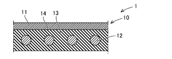
- FIG. 3 is a cross-sectional view of the basic configuration of the transducer 1.
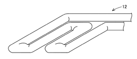
- FIG. It is a perspective view showing the heater 12.
- the electrostatic transducer (hereinafter referred to as “transducer”) includes an electrostatic sheet having a heater function.
- the transducer includes, for example, a base material and the electrostatic sheet attached to the attachment surface of the base material.
- the base material is an arbitrary member and is made of metal, resin, or other material.
- the mounting surface of the base material may be formed into a three-dimensional shape such as a curved surface, a composite flat surface (a shape formed by a plurality of flat surfaces), or a composite shape of a flat surface and a curved surface. You may form in planar shape.
- the electrostatic sheet can be attached to the attachment surface of the base material.
- the transducer can be used as the electrostatic sheet alone without the base material.
- the electrostatic sheet is placed on the mounting surface (front surface) of the base material.
- the electrostatic sheet as a whole is flexible. Flexible means having flexibility and being stretchable in the plane direction. Therefore, even if the mounting surface of the base material has a three-dimensional shape, the electrostatic sheet can be mounted along the mounting surface of the base material. In particular, wrinkling of the electrostatic sheet can be suppressed by mounting the electrostatic sheet on the mounting surface of the base material while stretching the electrostatic sheet in the surface direction.
- the electrostatic sheet can function as an actuator or a sensor by utilizing the change in electrostatic capacitance between a pair of electrodes.
- the electrostatic sheet may include at least one of the pair of electrodes, and is not limited to the configuration including the pair of electrodes. Of course, the electrostatic sheet may include a pair of electrodes.
- the electrostatic sheet can function as an actuator that generates vibration, sound, etc. by utilizing the change in electrostatic capacitance between the electrodes. Further, the electrostatic sheet can function as a sensor that detects a pushing force or the like from the outside or a sensor that detects contact or approach of a conductor having a potential by utilizing a change in capacitance between the electrodes. ..
- the electrostatic sheet functions as an actuator, when a voltage is applied to the electrodes, the dielectric body is deformed according to the potential between the electrodes, and the deformation of the dielectric body causes vibration.
- the electrostatic sheet functions as a sensor that detects the pressing force, the dielectric is deformed due to the input of external pressing force, vibration, sound, etc. (hereinafter, external pressing force, etc.).
- external pressing force etc.
- the electrostatic capacitance between the electrodes changes, and by detecting the voltage corresponding to the electrostatic capacitance between the electrodes, the pushing force or the like from the outside is detected.
- the electrostatic sheet functions as a sensor that detects contact or approach
- the capacitance between the electrodes changes due to the contact or approach of a conductor having a potential, and the changed capacitance between the electrodes is detected.
- the contact or approach of the conductor is detected by detecting the corresponding voltage.
- the transducer can be applied to, for example, the surface of a pointing device such as a mouse or joystick, or the surface of a vehicle part.
- vehicle parts include a steering wheel, a door knob, a shift lever, an armrest, a door trim, a center trim and a center console.
- the base material is formed of a non-flexible material such as metal or resin. That is, the transducer can apply heat to the target person in addition to detecting the state (operation, etc.) of the target person and applying vibration to the target person.
- the transducer may be arranged on the surface layer side of the seat seat surface or the surface layer side of the backrest surface.
- the transducer may be configured such that an electrostatic sheet having a heater function is attached to a base material formed of a flexible material such as a resin film.
- the transducer may be configured by an electrostatic sheet having a heater function without including the base material.
- the transducer 1 includes an electrostatic sheet 10 having a heater function, as shown in FIG.
- the electrostatic sheet 10 is formed in a sheet shape as a whole and is flexible.
- the term “flexible” means that it has flexibility and can be stretched in the plane direction.
- the electrostatic sheet 10 is attached to the attachment surface of the above-mentioned base material (not shown in FIG. 1). As shown in FIG. 1, the electrostatic sheet 10 includes at least an electrode sheet 11, a heater 12, and an insulating layer 13. The electrostatic sheet 10 may have a configuration other than the electrode sheet 11, the heater 12, and the insulating layer 13.
- the electrode sheet 11 has conductivity. Furthermore, the electrode sheet 11 is flexible.
- the electrode sheet 11 is formed of, for example, a conductive elastomer, a conductive cloth, a metal foil, or the like.
- the electrode sheet 11 is made of a conductive elastomer
- the electrode sheet 11 is formed of an elastomer containing a conductive filler. That is, the electrode sheet 11 is formed by using an elastomer as a base material and containing a conductive filler.
- the electrode sheet 11 is made of, for example, a thermoplastic elastomer.
- the electrode sheet 11 may be formed of the thermoplastic elastomer itself, or may be formed of an elastomer crosslinked by heating the thermoplastic elastomer as a raw material.
- the electrode sheet 11 can be selected from one or more of styrene-based, olefin-based, vinyl chloride-based, urethane-based, ester-based, amide-based, and other elastomers.
- examples of the styrene elastomer include SBS, SEBS, SEPS and the like.
- examples of the olefin elastomer include EEA, EMA, EMMA and the like, as well as a copolymer of ethylene and ⁇ -olefin (ethylene-octene copolymer) and the like.
- the electrode sheet 11 may contain rubber or resin other than the thermoplastic elastomer.
- rubber such as ethylene-propylene rubber (EPM, EPDM)
- EPM ethylene-propylene rubber
- the electrode sheet 11 may contain a flexibility-imparting component such as a plasticizer.
- the conductive cloth is a woven or non-woven fabric formed of conductive fibers.
- the conductive fiber is formed by coating the surface of the flexible fiber with a conductive material.
- the conductive fiber is formed, for example, by plating the surface of a resin fiber such as polyethylene with copper or nickel.
- the metal foil has a plurality of through holes similarly to the conductive cloth. Therefore, the electrode sheet 11 has flexibility and can be expanded in the surface direction as the through holes are deformed.
- the metal foil may be any conductive metal material, and for example, a copper foil, an aluminum foil or the like can be applied.
- the heater 12 is formed into a sheet shape (planar shape) by a heater wire.
- the heater 12 is arranged to face one surface of the electrode sheet 11.
- the heater wire is a metal alloy-based material, and for example, nickel chrome, iron chrome, or the like is applied.
- the insulating layer 13 is formed in a sheet shape and is sandwiched at least between the electrode sheet 11 and the heater 12.
- the insulating layer 13 may be formed so as to cover both surfaces (the upper and lower surfaces of FIG. 1) of the heater 12. Note that FIG. 1 illustrates the case where the insulating layer 13 covers both surfaces of the heater 12.
- the insulating layer 13 is made of a flexible material.
- the insulating layer 13 is formed of, for example, a thermoplastic material, particularly a thermoplastic elastomer. Further, the insulating layer 13 may be made of a non-thermoplastic elastomer foam material, a non-woven fabric, a woven fabric, or the like.
- the insulating layer 13 can also function as a dielectric layer in the electrostatic sheet 10.
- the electrostatic sheet 10 further includes an electrode fusion layer 14.
- the electrode fusion layer 14 is made of a fusion material.
- the electrode fusing layer 14 joins the electrode sheet 11 and the insulating layer 13 by fusing (thermal fusion) of the electrode fusing layer 14 itself.
- the electrode fusing layer 14 may be configured as a part of the electrode sheet 11 or may be configured as a part of the insulating layer 13.
- the electrode fusing layer 14 may be formed as a part of the electrode sheet 11 and also as a part of the insulating layer 13.
- the electrode fusion bonding layer 14 may be joined to the electrode sheet 11 and the insulating layer 13 as a separate member.
- a method of manufacturing the above-described basic configuration of the transducer 1 will be described.
- a laminated body in which the electrode sheet 11, the insulating layer 13, and the heater 12 are laminated in this order, which are components of the electrostatic sheet 10, is prepared (preparation step).
- the insulating layer 13 may be formed integrally with the heater 12 in advance, or may be formed separately from the electrode sheet 11 and the heater 12.
- the laminate is heated and pressed (heating and pressing step). Then, the electrode fusion layer 14 joins the electrode sheet 11 and the insulating layer 13. As described above, the electrode fusing layer 14 is a part of the electrode sheet 11, a part of the insulating layer 13, or a material different from the electrode sheet 11 and the insulating layer 13. In this way, the electrostatic sheet 10 is manufactured. Then, the electrostatic sheet 10 is attached to a base material (not shown). When the substrate is not present, the transducer 1 is completed by manufacturing the electrostatic sheet 10.
- the electrostatic sheet 10 forming the transducer 1 is integrally formed in a sheet shape as a whole. Therefore, the number of manufacturing steps of the transducer 1 can be reduced regardless of whether the transducer 1 is provided with a base material or not.
- the constituent members 11, 12, and 13 of the transducer 1 are integrally formed, when the constituent members 11, 12, and 13 of the transducer 1 are mounted on the mounting surface of the base material, mounting on the mounting surface is performed.
- the process can be one process. Therefore, the number of manufacturing steps can be reduced.
- the mounting step can be performed in one step with respect to the mounting surface, the more complicated the mounting surface is, the more effective the manufacturing process can be reduced.
- the number of manufacturing steps can be reduced also when the constituent members 11, 12, and 13 of the transducer 1 are attached to a flexible base material.
- the bonding between the electrode sheet 11 and the insulating layer 13 is performed by a fusion material that can be softened by heat. Therefore, the electrostatic sheet 10 having a heater function can be manufactured without using the volatile adhesive and the organic solvent. That is, the environment-friendly transducer 1 can be manufactured.
- the electrode fusing layer 14 is composed of a part of the electrode sheet 11 or a part of the insulating layer 13, no special member is required as the electrode fusing layer 14. As a result, it is possible to further reduce the cost.
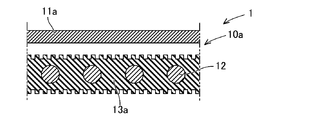
- the configuration of the electrostatic sheet 10a of the first example will be described with reference to FIGS. 3 and 4.
- the electrode sheet 11a that constitutes the electrostatic sheet 10a is formed by including a thermoplastic material.
- the electrode sheet 11a is made of a thermoplastic elastomer. That is, the electrode sheet 11a can be softened by heating and pressurizing and fused to the mating member.
- the insulating layer 13a is made of a thermoplastic material, for example, a thermoplastic elastomer.
- the thermoplastic material of the insulating layer 13a has a higher softening point than the thermoplastic material of the electrode sheet 11a.
- the insulating layer 13a has irregularities on the joint surface with the electrode sheet 11a. For example, by forming an uneven surface on a mold for molding the insulating layer 13a, it is possible to form unevenness on the bonding surface of the insulating layer 13a with the electrode sheet 11a.
- the electrostatic sheet 10a is manufactured by laminating the electrode sheet 11a and the insulating layer 13a and heating and pressing the laminated body.
- the electrode sheet 11a is formed of a thermoplastic material having a softening point lower than that of the insulating layer 13a. Therefore, when the laminated body is heated and pressed, the thermoplastic material of the electrode sheet 11a is first softened and enters the concave portion of the insulating layer 13a.
- a part of the electrode sheet 11a functions as an electrode fusion layer 14 that joins the electrode sheet 11a and the uneven surface of the insulating layer 13a by fusion of itself.
- a part of the electrode sheet 11a enters the concave portion of the insulating layer 13a, thereby exerting an anchor effect and increasing the bonding force between the electrode sheet 11a and the insulating layer 13a.
- the insulating layer 13a is made of a thermoplastic material, but a non-thermoplastic material may be applied. In this case, naturally, when the laminated body is heated and pressed, the thermoplastic material of the electrode sheet 11a is softened before the insulating layer 13a.
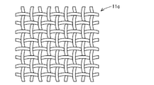
- the insulating layer 13a is a non-woven fabric or a woven fabric formed of fibers of a non-thermoplastic material. Since the non-woven fabric or the woven fabric is formed of fibers, at least the joint surface of the insulating layer 13a with the electrode sheet 11a has irregularities as shown in FIG. Specifically, the joint surface of the insulating layer 13a has fibers and irregularities formed by spaces between the fibers. That is, the insulating layer 13a has an uneven surface in which fibers are convex portions and concave portions are between adjacent fibers.
- the electrode sheet 11a and the insulating layer 13a are laminated, and the laminated body is heated and pressed to manufacture the electrostatic sheet 10a. That is, when the laminated body is heated and pressed, the thermoplastic material of the electrode sheet 11a is softened and enters the concave portion of the insulating layer 13a. And a part of electrode sheet 11a functions as electrode fusion layer 14 which joins electrode sheet 11a and the uneven surface of insulating layer 13a by fusion of itself.
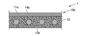
- Electrostatic sheet 10b of the fourth example The configuration of the electrostatic sheet 10b of the fourth example will be described with reference to FIGS.
- the electrode sheet 11a forming the electrostatic sheet 10b is formed by including a thermoplastic material, as in the first example.
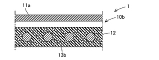
- the insulating layer 13b is formed of a non-thermoplastic foam material. As shown in FIG. 5, the insulating layer 13b has unevenness formed by bubbles on at least the surface. Of course, the insulating layer 13b has recesses (air bubbles) inside.
- the electrostatic sheet 10a is manufactured. That is, when the laminated body is heated and pressed, the thermoplastic material of the electrode sheet 11a is softened and enters the concave portion of the insulating layer 13b. And a part of electrode sheet 11a functions as electrode fusion layer 14 which joins electrode sheet 11a and the uneven surface of insulating layer 13b by fusion of itself.
- Electrostatic sheet 10c of the fifth example The configuration of the electrostatic sheet 10c of the fifth example will be described with reference to FIGS. 7 and 8.
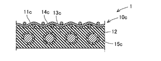
- the electrostatic sheet 10 includes at least an electrode sheet 11c, a heater 12, an insulating layer 13c, an electrode fusion layer 14c, and a heater fusion layer 15c.
- the electrode sheet 11c has conductivity and flexibility and stretchability in the plane direction.
- the electrode sheet 11c is, for example, a conductive cloth.
- the insulating layer 13c is formed of, for example, a thermoplastic material, particularly a thermoplastic elastomer.
- the electrode fusing layer 14c may be configured as a part of the insulating layer 13c or may be joined to the insulating layer 13c as a separate member.
- the heater fusion layer 15c is made of a fusion material.
- the heater fusing layer 15c joins the heater 12 and the insulating layer 13c by fusing (heat fusing) the heater fusing layer 15c itself.
- the heater 12 is joined by the heater fusion layer 15c while being embedded in the insulating layer 13c.
- the heater fusion bonding layer 15c may be configured as a part of the insulating layer 13c or may be joined to the insulating layer 13c as a separate member.
- the heater fusion bonding layer 15c is formed of a thermoplastic material that is a fusion bonding material, and is configured as a part of the insulating layer 13c.
- the heater fusing layer 15c as a part of the insulating layer 13c joins the heater 12 and the insulating layer 13c by fusing themselves.
- a method of manufacturing the electrostatic sheet 10c will be described with reference to FIG.
- the material of the insulating layer 13c is assumed to be formed of a thermoplastic material.
- a laminated body is prepared in which the electrode sheet 11c, the first material 13c1 of the insulating layer 13c, the heater 12, and the second material 13c2 of the insulating layer 13c are laminated in this order (preparation step). Then, the laminated body is heated and pressed (heating and pressing step). Then, the first material 13c1 of the insulating layer 13c softens and functions as a fusion material, and is bonded to the electrode sheet 11c. The portion fused to the electrode sheet 11c becomes the electrode fusion layer 14c.
- first material 13c1 and the second material 13c2 of the insulating layer 13c are softened to function as a fusion material and are bonded to the heater 12.
- the portion fused to the heater 12 becomes the heater fusion layer 15c.
- the first material 13c1 and the second material 13c2 of the insulating layer 13c are integrated to form the insulating layer 13c.
- the heater 12 is embedded in the insulating layer 13c. In this way, the electrostatic sheet 10c of the transducer 1 is manufactured.
- the insulating layer 13c is formed of a thermoplastic material, and the electrode fusing layer 14c and the heater fusing layer 15c are formed as a part of the insulating layer 13c. Therefore, dedicated members are not required for the electrode fusion layer 14c and the heater fusion layer 15c. As a result, it is possible to further reduce the cost.
- the electrode fusing layer 14c and the heater fusing layer 15c are arranged as separate members from the insulating layer 13c, the electrode sheet 11c, the material of the electrode fusing layer 14c, the insulating layer 13c, the heater fusing layer A laminated body in which the material of 15c and the heater 12 are laminated in this order is prepared (preparation step). Then, the laminated body is heated and pressed (heating and pressing step). Then, the material of the electrode fusion layer 14c softens and functions as a fusion material to bond the electrode sheet 11c and the insulating layer 13c. Further, the material of the heater fusion bonding layer 15c softens and functions as a fusion bonding material to bond the heater 12 and the insulating layer 13c.
- Example of transducer 1 A plurality of examples will be given to describe the transducer 1 having the basic configuration of the transducer 1 described above and including other elements.
- the electrostatic sheet 10 of the transducer 1 is configured to have a pair of electrode sheets.
- the configuration of the transducer 100 of the first example will be described with reference to FIG.
- the transducer 100 includes an electrostatic sheet 110 having a heater function.
- the electrostatic sheet 110 is flexible as a whole.
- the electrostatic sheet 110 has a configuration using the electrostatic sheet 10a or 10b of any one of the first to fourth examples.
- the same components as those of the electrostatic sheets 10a and 10b are designated by the same reference numerals and detailed description thereof will be omitted.
- the electrostatic sheet 110 includes at least the first electrode sheet 116, the second electrode sheet 11a, the heater 12, the interelectrode insulating layer 117, the back surface side insulating layers 13a and 13b, and the back surface side fusion bonding layers 14a and 14b.
- the first electrode sheet 116 has the same configuration as the electrode sheet 11a in the electrostatic sheet 10a, 10b of any one of the first to fourth examples.
- the first electrode sheet 116 is arranged on the surface layer side.
- the second electrode sheet 11a corresponds to a portion functioning as the electrode sheet 11a in any one of the electrostatic sheets 10a and 10b of the first to fourth examples.
- the second electrode sheet 11a is arranged to face the back surface of the first electrode sheet 116.
- the heater 12 corresponds to a portion functioning as the heater 12 in any one of the electrostatic sheets 10a and 10b of the first to fourth examples.
- the heater 12 is arranged to face the back surface of the second electrode sheet 11a.
- the inter-electrode insulating layer 117 is formed in a sheet shape and is sandwiched between the first electrode sheet 116 and the second electrode sheet 11a.
- the interelectrode insulating layer 117 is made of an elastically deformable material.
- the inter-electrode insulating layer 117 is formed of, for example, a thermoplastic material, particularly a thermoplastic elastomer. Further, the inter-electrode insulating layer 117 may be made of a non-thermoplastic elastomer foam material, a non-woven fabric or the like.
- the interelectrode insulating layer 117 functions as a dielectric layer in the electrostatic sheet.
- the back side insulating layers 13a and 13b are formed in a sheet shape and are sandwiched between the second electrode sheet 11a and the heater 12.
- the back surface side insulating layers 13a and 13b correspond to the portions functioning as the insulating layers 13a and 13b in the electrostatic sheets 10a and 10b of any one of the first to fourth examples.
- the back surface side insulating layers 13a and 13b are formed of the same material as the interelectrode insulating layer 117. Since both are made of the same material, the cost can be reduced.
- the back side fusion layers 14a and 14b are formed of a fusion material.
- the back side fusion layers 14a and 14b join the second electrode sheet 11a and the back side insulation layers 13a and 13b, and function as the electrode fusion layers 14a and 14b in the electrostatic sheets 10a and 10b of the first example. Corresponding to.
- the first electrode sheet 116, the inter-electrode insulating layer 117, and the second electrode sheet 11a are integrally formed in a pre-laminated state (preparation step). Further, the heater 12 and the back surface side insulating layers 13a and 13b are integrally formed in advance (preparation step). And the laminated body which laminated
- the second electrode sheet 11a is softened and fused to the uneven surfaces of the back surface side insulating layers 13a and 13b. That is, a part of the second electrode sheet 11a forms the back surface side fusion bonding layers 14a and 14b. In this way, the electrostatic sheet 110 of the transducer 100 of the first example is manufactured.
- the first electrode sheet 116, the second electrode sheet 11a, and the inter-electrode insulating layer 117 are located on the front side of the heater 12. That is, the heater 12 is not located between the first electrode sheet 116 and the second electrode sheet 11a and on the surface side of the first electrode sheet 116. As a result, it is possible to suppress the influence of the heater 12 on the detection performance or the driving performance, so that the high detection performance or the driving performance can be exhibited.
- the interelectrode insulating layer 117 can sufficiently function as a heater by using a material having good thermal conductivity.
- the back surface side insulating layers 13a and 13b that are in direct contact with the heater 12 are formed of a material having good thermal conductivity, sufficient heat is diffused before the heat becomes sufficiently high, so that sufficient heat is generated on the surface layer. Hard to be transmitted to. Therefore, by forming the back side insulating layers 13a and 13b with a material having a poor thermal conductivity to some extent, heat can be effectively transferred to the surface layer.
- the back surface side insulating layers 13a and 13b are made of a foam material, a non-woven fabric, a woven fabric or the like having pores formed therein, heat can be more effectively transferred to the surface layer.
- the configuration of the transducer 200 of the second example will be described with reference to FIG.
- the transducer 200 includes an electrostatic sheet 210 having a heater function.
- the electrostatic sheet 110 is flexible as a whole.
- the electrostatic sheet 210 has a configuration using any one of the electrostatic sheets 10a and 10b of the first to fourth examples. In this example, the same components as those of the electrostatic sheets 10a and 10b are designated by the same reference numerals and detailed description thereof will be omitted.
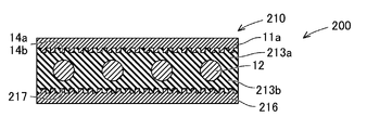
- the electrostatic sheet 210 includes at least a first electrode sheet 11a, a heater 12, a second electrode sheet 216, a first insulating layer 213a (13a, 13b), a second insulating layer 213b (13a, 13b), and a first electrode fusion bonding.
- the layers 14a and 14b and the second electrode fusion layer 217 are provided.
- the first electrode sheet 11a has the same structure as the electrode sheet 11a in the electrostatic sheet 10a, 10b of any one of the first to fourth examples.
- the first electrode sheet 11a is arranged on the surface layer side.
- the heater 12 is arranged to face the back surface of the first electrode sheet 11a.
- the second electrode sheet 216 has the same structure as the first electrode sheet 11a.
- the second electrode sheet 216 is arranged to face the back surface side of the heater 12. That is, the heater 12 is interposed between the first electrode sheet 11a and the second electrode sheet 216.
- the first insulating layer 213a is formed in a sheet shape and is sandwiched between the first electrode sheet 11a and the heater 12.
- the first insulating layer 213a functions as a part of the insulating layers 13a and 13b in the electrostatic sheets 10a and 10b of any one of the first to fourth examples.
- the second insulating layer 213b is formed in a sheet shape and is sandwiched between the heater 12 and the second electrode sheet 216.
- the second insulating layer 213b functions as another part of the insulating layers 13a and 13b in the electrostatic sheets 10a and 10b of the first to fourth examples. That is, the first insulating layer 213a and the second insulating layer 213b are made of the same material.
- the first electrode fusion layers 14a and 14b are made of a fusion material.
- the first electrode fusing layers 14a and 14b join the first electrode sheet 11a and the first insulating layer 213a.
- the first electrode fusing layers 14a and 14b function as the electrode fusing layers 14a and 14b in any one of the electrostatic sheets 10a and 10b of the first to fourth examples.
- the second electrode fusion layer 217 is made of a fusion material.
- the second electrode fusing layer 217 joins the second electrode sheet 216 and the second insulating layer 213b.
- the second electrode fusing layer 217 has the same configuration as the first electrode fusing layers 14a and 14b.
- a method of manufacturing the second example transducer 200 will be described.
- the first insulating layer 213a, the heater 12, and the second insulating layer 213b are integrally formed in advance.
- a laminated body in which the first electrode sheet 11a, the integrally molded product, and the second electrode sheet 216 are laminated in this order is prepared (preparation step).
- the first electrode sheet 11a is softened and fused to the uneven surface of the first insulating layer 213a. That is, a part of the first electrode sheet 11a forms the first electrode fusing layers 14a and 14b.
- the second electrode sheet 216 is softened and fused to the uneven surface of the second insulating layer 213b. That is, a part of the second electrode sheet 216 forms the second electrode fusing layer 217. In this way, the electrostatic sheet 210 of the transducer 200 of the second example is manufactured.
- the heater 12 is sandwiched between the first electrode sheet 11a and the second electrode sheet 216. Therefore, the thickness of the electrostatic sheet 210 can be reduced. Therefore, a small electrostatic sheet 210 can be manufactured.
- the configuration of the transducer 300 of the third example will be described with reference to FIG.
- the transducer 300 includes an electrostatic sheet 310 having a heater function.
- the electrostatic sheet 310 is flexible as a whole.
- the electrostatic sheet 310 has a configuration using one of the electrostatic sheets 10a and 10b of the first to fourth examples.
- the same components as those of the electrostatic sheets 10a and 10b are designated by the same reference numerals, and detailed description thereof will be omitted.
- the electrostatic sheet 310 includes at least the heater 12, the first electrode sheet 11a, the second electrode sheet 316, the surface side insulating layers 13a and 13b, the inter-electrode insulating layer 317, and the surface side fusion layers 14a and 14b.
- the first electrode sheet 11a has the same configuration as the electrode sheet 11a in the electrostatic sheets 10a and 10b of any one of the first to fourth examples.
- the first electrode sheet 116 is arranged on the surface layer side.
- the heater 12 is arranged on the surface side.
- the heater 12 corresponds to a portion functioning as the heater 12 in any one of the electrostatic sheets 10a and 10b of the first to fourth examples.
- the first electrode sheet 11a is arranged to face the back surface of the heater 12.
- the 1st electrode sheet 11a respond
- the second electrode sheet 316 is arranged to face the back surface of the first electrode sheet 11a.
- the second electrode sheet 316 has the same configuration as the first electrode sheet 11a.
- the front-side insulating layers 13a and 13b are formed in a sheet shape and sandwiched between the heater 12 and the first electrode sheet 11a.
- the front surface side insulating layers 13a and 13b correspond to the portions functioning as the insulating layers 13a and 13b in the electrostatic sheets 10a and 10b of any one of the first to fourth examples.
- the interelectrode insulating layer 317 is formed in a sheet shape, and is sandwiched between the first electrode sheet 11a and the second electrode sheet 316.
- the inter-electrode insulating layer 317 is made of an elastically deformable material.
- the inter-electrode insulating layer 317 is formed of, for example, a thermoplastic material, particularly a thermoplastic elastomer. Further, the inter-electrode insulating layer 317 may be made of a non-thermoplastic elastomer foam material, a non-woven fabric, or the like.
- the interelectrode insulating layer 317 functions as a dielectric layer in the electrostatic sheet.
- the surface-side insulating layers 13a and 13b and the inter-electrode insulating layer 317 are made of different materials.
- the surface side insulating layers 13a and 13b are formed of a material having a higher thermal conductivity than the interelectrode insulating layer 317.
- the interelectrode insulating layer 317 does not need to be a material having high thermal conductivity. By forming the interelectrode insulating layer 317 from a material that effectively exhibits a dielectric, the detection performance or drive performance of the electrostatic sheet 310 can be improved.
- the first electrode sheet 11a, the inter-electrode insulating layer 317, and the second electrode sheet 316 are integrally formed in a previously laminated state (preparation step). Further, the heater 12 and the front surface side insulating layers 13a and 13b are integrally formed in advance (preparation step). And the laminated body which laminated
- the first electrode sheet 11a is softened and fused to the uneven surfaces of the surface-side insulating layers 13a and 13b. That is, a part of the first electrode sheet 11a forms the surface-side fusion bonding layers 14a and 14b. In this way, the electrostatic sheet 310 of the transducer 300 of the third example is manufactured.
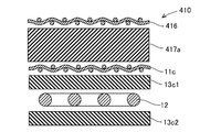
- the transducer 400 includes a base material 430 and an electrostatic sheet 410 attached to the attachment surface of the base material 430.
- the electrostatic sheet 410 has a heater function.
- the electrostatic sheet 410 is flexible as a whole.
- the electrostatic sheet 410 has a configuration using the electrostatic sheet 10c of the fifth example.
- parts having the same configurations as those of the electrostatic sheet 10c of the fifth example are designated by the same reference numerals, and detailed description thereof will be omitted.
- the electrostatic sheet 410 includes at least the first electrode sheet 416, the second electrode sheet 11c, the heater 12, the inter-electrode insulating layer 417, the back side insulating layer 13c, the inter-electrode first fusion layer 418, and the inter-electrode second fusion layer.
- a layer 419, a backside fusion layer 14c, and a heater fusion layer 15c are provided.
- the electrostatic sheet 410 further includes a surface protective layer 420, a protective fusion bonding layer 421, and a base material fusion bonding layer 422.
- the electrostatic sheet 410 may be configured without the surface protective layer 420, the protective fusion bonding layer 421, and the base material fusion bonding layer 422.
- the first electrode sheet 416 has the same configuration as the electrode sheet 11c in the electrostatic sheet 10c of the fifth example.
- the first electrode sheet 416 is arranged on the surface layer side.
- the second electrode sheet 11c corresponds to a portion that functions as the electrode sheet 11c in the electrostatic sheet 10c of the fifth example.
- the second electrode sheet 11c is arranged to face the back surface of the first electrode sheet 416.
- the heater 12 corresponds to a portion that functions as the heater 12 in the electrostatic sheet 10c of the fifth example.
- the heater 12 is arranged to face the back surface of the second electrode sheet 11c.
- the inter-electrode insulating layer 417 is formed in a sheet shape and is sandwiched between the first electrode sheet 416 and the second electrode sheet 11c.
- the interelectrode insulating layer 417 is made of an elastically deformable material.
- the inter-electrode insulating layer 417 is formed of, for example, a thermoplastic material, particularly a thermoplastic elastomer. Further, the inter-electrode insulating layer 417 can also be made of a non-thermoplastic elastomer foam material, non-woven fabric, or the like.
- the interelectrode insulating layer 417 functions as a dielectric layer in the electrostatic sheet.
- the back side insulating layer 13c is formed in a sheet shape and is sandwiched between the second electrode sheet 11c and the heater 12.
- the back surface side insulating layer 13c corresponds to a portion functioning as the insulating layer 13c in the electrostatic sheet 10c of the fifth example.
- the back surface side insulating layer 13c is formed of the same material as the interelectrode insulating layer 417. Since both are made of the same material, the cost can be reduced.
- the first inter-electrode fusion layer 418 is made of a fusion material. That is, the inter-electrode first fusion-bonding layer 418 exerts a bonding force by being subjected to heat treatment. For example, the inter-electrode first fusion bonding layer 418 exerts a bonding force by being heated and pressed.
- the inter-electrode first fusion bonding layer 418 joins the first electrode sheet 416 and the inter-electrode insulating layer 417.
- the first inter-electrode fusion layer 418 may be configured as a part of the inter-electrode insulating layer 417, or may be joined to the inter-electrode insulating layer 417 as a separate member.
- the inter-electrode first fusion-bonding layer 418 is formed of a thermoplastic material that is a fusion-bonding material, and is configured as a part of the inter-electrode insulating layer 417.
- the inter-electrode first fusion-bonding layer 418 as a part of the inter-electrode insulation layer 417 joins the first electrode sheet 416 and the inter-electrode insulation layer 417 by fusion (thermal fusion).
- the second inter-electrode fusion layer 419 is made of a fusion material.
- the inter-electrode second fusing layer 419 is similar to the inter-electrode first fusing layer 418.
- the inter-electrode second fusion bonding layer 419 joins the inter-electrode insulating layer 417 and the second electrode sheet 11c.
- the inter-electrode second fusion bonding layer 419 may be configured as a part of the inter-electrode insulating layer 417 or may be joined to the inter-electrode insulating layer 417 as a separate member.
- the inter-electrode second fusion-bonding layer 419 is formed of a thermoplastic material that is a fusion-bonding material, and is configured as a part of the inter-electrode insulating layer 417.
- the inter-electrode second fusion bonding layer 419 as a part of the inter-electrode insulation layer 417 joins the inter-electrode insulation layer 417 and the second electrode sheet 11c by fusion (thermal fusion).
- the backside fusion layer 14c is formed of a fusion material.
- the back surface side fusion layer 14c corresponds to a portion which joins the second electrode sheet 11c and the back surface side insulation layer 13c and functions as the electrode fusion layer 14c in the electrostatic sheet 10c of the fifth example.
- the heater fusion layer 15c is made of a fusion material.
- the heater fusion bonding layer 15c joins the back surface side insulating layer 13c and the heater 12 and corresponds to a portion functioning as the heater fusion bonding layer 15c in the electrostatic sheet 10c of the fifth example.
- the heater 12 is bonded by the heater fusion bonding layer 15c on the back surface side of the second electrode sheet 11c while being embedded in the back surface side insulating layer 13c.
- the surface protection layer 420 is formed in a sheet shape and covers the surface side of the first electrode sheet 416.
- the surface protection layer 420 may be formed of a thermoplastic material, particularly a thermoplastic elastomer.
- the surface protection layer 420 may be formed of a part of the material of the inter-electrode insulating layer 417, or may be formed as a separate member from the inter-electrode insulating layer 417.
- a resin insulating sheet having an adhesive layer or an adhesive layer may be used instead of the thermoplastic material.
- the protective fusion bonding layer 421 is made of a fusion bonding material.
- the protective fusion bonding layer 421 joins the first electrode sheet 416 and the surface protective layer 420 together.
- the protective fusion bonding layer 421 may be configured as a part of the surface protective layer 420, or may be joined to the surface protective layer 420 as a separate member. Further, the protective fusion bonding layer 421 may be formed of a part of the material of the interelectrode insulating layer 417. However, when the surface protective layer 420 is an insulating sheet, the protective fusion bonding layer 421 becomes unnecessary.
- the base material fusion layer 422 is made of a fusion material, and joins the back surface side insulating layer 13c and the mounting surface of the base material 430.
- the base material fusion bonding layer 422 may be configured as a part of the back surface side insulating layer 13c, or may be joined to the back surface side insulating layer 13c as a separate member.
- the first electrode sheet 416, the material 417a of the inter-electrode insulating layer 417, the second electrode sheet 11c, the first material 13c1 of the back side insulating layer 13c, the heater 12, and the second material 13c2 of the back side insulating layer 13c were laminated in this order.
- a laminated body is prepared (preparation process). Then, the laminated body is heated and pressed (heating and pressing step).
- the material 417a of the interelectrode insulating layer 417 softens and functions as a fusion material, and is bonded to the first electrode sheet 416.
- the portion fused to the first electrode sheet 416 becomes the inter-electrode first fusion layer 418.
- the material 417a of the inter-electrode insulating layer 417 passes through the through hole of the first electrode sheet 416 and moves to the surface layer side of the first electrode sheet 416.
- the surface protection layer 420 is formed of the material 417a of the interelectrode insulating layer 417.
- the portion fused to the surface protective layer 420 and the first electrode sheet 416 becomes the protective fused layer 421.
- the material 417a of the interelectrode insulating layer 417 softens and functions as a fusion material, and is bonded to the second electrode sheet 11c.
- the portion fused to the second electrode sheet 11c becomes the inter-electrode second fused layer 419.
- the material 417a of the inter-electrode insulating layer 417 passes through the through hole of the second electrode sheet 11c and moves to the back surface side of the second electrode sheet 11c. Then, the material 417a that has moved to the back surface side of the second electrode sheet 11c is joined to the first material 13c1 of the back surface side insulating layer 13c.
- the first material 13c1 of the back surface side insulating layer 13c softens and functions as a fusion material, and is bonded to the back surface side of the second electrode sheet 11c. That is, a part of the material 417a of the interelectrode insulating layer 417 and a part of the first material 13c1 of the back surface side insulating layer 13c become the back surface side fusion layer 14c.
- the first material 13c1 and the second material 13c2 of the back surface side insulating layer 13c are softened to function as a fusion material and are bonded to the heater 12.
- the portion fused to the heater 12 becomes the heater fusion layer 15c.
- the back surface side insulating layer 13c is formed by integrating the first material 13c1 and the second material 13c2 of the back surface side insulating layer 13c.
- the heater 12 is in a state of being embedded in the back side insulating layer 13c. In this way, the electrostatic sheet 410 of the transducer 400 is manufactured.
- the base material fusion layer 422 can be formed by heating the back surface side insulating layer 13c and applying pressure to the base material 430. In this way, the transducer 400 is manufactured.
- the surface protection layer 420 is formed of the material 417a of the inter-electrode insulating layer 417, but an insulating sheet made of resin different from the material 417a of the inter-electrode insulating layer 417 is used. You can also
- a first laminated body in which the first electrode sheet 416, the material 417a of the interelectrode insulating layer 417, and the second electrode sheet 11c are laminated in this order is prepared (first laminated body preparing step), and the first laminated body is heated and heated. By pressing, the first molded body is molded (first molded body molding step). Then, a second laminated body is prepared by laminating the first material 13c1 of the back side insulating layer 13c, the heater 12, and the second material 13c2 of the back side insulating layer 13c in this order (second laminated body preparing step). The second molded body is molded by heating and pressing the laminated body (second molded body molding step).
- final laminate preparation step the final laminate in which the first compact and the second compact are laminated is prepared (final laminate preparation step), and the final laminate is heated and pressed to manufacture the electrostatic sheet 410 ( Final heat and pressure step).
- the first electrode sheet 416, the second electrode sheet 11c, and the inter-electrode insulating layer 417 are located on the surface side of the heater 12. That is, the heater 12 is not located between the first electrode sheet 416 and the second electrode sheet 11c and on the front surface side of the first electrode sheet 416. As a result, it is possible to suppress the influence of the heater 12 on the detection performance or the driving performance, so that the high detection performance or the driving performance can be exhibited.
- the inter-electrode insulating layer 417 and the back surface insulating layer 13c are made of a material having good thermal conductivity, so that the heater 12 sufficiently functions as a heater. can do.
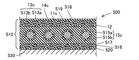
- the transducer 500 includes a base material 530 and an electrostatic sheet 510 attached to an attachment surface of the base material 530.
- the electrostatic sheet 510 has a heater function.
- the electrostatic sheet 510 is flexible as a whole.
- the electrostatic sheet 510 has a configuration using the electrostatic sheet 10c of the fifth example. Therefore, in this example, parts having the same configurations as those of the electrostatic sheet 10c of the fifth example are designated by the same reference numerals, and detailed description thereof will be omitted.
- the electrostatic sheet 510 includes at least the first electrode sheet 11c, the heater 12, the second electrode sheet 516, the first insulating layer 513a, the second insulating layer 513b, the first electrode fusion layer 14c, and the first heater fusion layer 515a.
- the electrostatic sheet 510 further includes a surface protective layer 518, a protective fusion bonding layer 519, and a base material fusion bonding layer 520.
- the electrostatic sheet 510 may be configured without the surface protective layer 518, the protective fusion bonding layer 519, and the base material fusion bonding layer 520.
- the first electrode sheet 11c is arranged on the surface side.
- the first electrode sheet 11c corresponds to a portion that functions as the electrode sheet 11c in the electrostatic sheet 10c of the fifth example.
- the heater 12 is arranged to face the back surface of the first electrode sheet 11c.
- the heater 12 corresponds to a portion that functions as the heater 12 in the electrostatic sheet 10c of the fifth example.
- the second electrode sheet 516 has the same structure as the first electrode sheet 11c.
- the second electrode sheet 516 is arranged to face the back surface side of the heater 12. That is, the heater 12 is interposed between the first electrode sheet 11c and the second electrode sheet 516.
- the first insulating layer 513a is formed in a sheet shape and is sandwiched between the first electrode sheet 11c and the heater 12.
- the first insulating layer 513a functions as a part of the insulating layer 13c in the electrostatic sheet 10c of the fifth example.
- the second insulating layer 513b is formed in a sheet shape and is sandwiched between the heater 12 and the second electrode sheet 516.
- the second insulating layer 513b functions as another part of the insulating layer 13c in the electrostatic sheet 10c of the fifth example. That is, the first insulating layer 513a and the second insulating layer 513b are formed of the same material.
- the first electrode fusion layer 14c is formed of a fusion material.
- the first electrode fusing layer 14c joins the first electrode sheet 11c and the first insulating layer 513a.
- the first electrode fusing layer 14c may be configured as a part of the first insulating layer 513a or may be joined to the first insulating layer 513a as a separate member.
- the first heater fusion layer 515a is made of a fusion material.
- the first heater fusion bonding layer 515a bonds the first insulating layer 513a and the heater 12. That is, the first heater fusion bonding layer 515a is a portion that is fused to the front surface side of the heater 12.
- the first heater fusion bonding layer 515a may be configured as a part of the first insulating layer 513a, or may be joined to the first insulating layer 513a as a separate member.
- the second heater fusion layer 515b is made of a fusion material.
- the second heater fusion bonding layer 515b joins the heater 12 and the second insulating layer 513b. That is, the second heater fusion bonding layer 515b is a portion that is fused to the back surface side of the heater 12.
- the second heater fusion bonding layer 515b may be configured as a part of the second insulating layer 513b, or may be joined to the second insulating layer 513b as a separate member.
- the first heater fusing layer 515a and the second heater fusing layer 515b function as the heater fusing layer 15c in the electrostatic sheet 10c of the fifth example.
- the heater 12 is embedded in the first insulating layer 513a and the second insulating layer 513b between the first electrode sheet 11c and the second electrode sheet 516, and is embedded in the first heater fusion layer 515a and the second heater layer 515a. They are joined by a heater fusion layer 515b.
- the second electrode fusion layer 517 is made of a fusion material.
- the second electrode fusing layer 517 joins the second insulating layer 513b and the second electrode sheet 516 together.
- the second electrode fusing layer 517 may be configured as a part of the second insulating layer 513b, or may be joined to the second insulating layer 513b as a separate member.
- the surface protective layer 518 is formed in a sheet shape and covers the surface side of the first electrode sheet 11c.
- the surface protective layer 518 may be formed of a thermoplastic material, particularly a thermoplastic elastomer.
- the surface protection layer 518 may be formed of a part of the material of the first insulating layer 513a, or may be formed as a separate member from the first insulating layer 513a. Further, as the surface protective layer 518, a resin insulating sheet having an adhesive layer or an adhesive layer may be applied instead of the thermoplastic material.
- the protective fusing layer 519 is configured similarly to the protective fusing layer 421 in the transducer 400 of the fourth example.
- the base material fusion bonding layer 520 is formed of a fusion bonding material, and joins the second insulating layer 513b and the mounting surface of the base material 530.
- the base material fusion bonding layer 520 may be configured as a part of the second insulating layer 513b or may be joined to the second insulating layer 513b as a separate member.
- the material 13c1 of the first insulating layer 513a softens and functions as a fusion material, and is bonded to the first electrode sheet 11c.
- the portion fused to the first electrode sheet 11c becomes the first electrode fusion layer 14c.
- the material 13c1 of the first insulating layer 513a passes through the through holes of the first electrode sheet 11c to form the surface protective layer 518 and the protective fusion bonding layer 519. This point is the same as the surface protective layer 420 and the protective fusion bonding layer 421 in the transducer 400 of the fourth example.
- the material 13c1 of the first insulating layer 513a and the material 13c2 of the second insulating layer 513b are softened to function as a fusion material and are bonded to the heater 12.
- the portions fused to the heater 12 become the first heater fusion layer 515a and the second heater fusion layer 515b.
- the material 13c1 of the first insulating layer 513a and the material 13c2 of the second insulating layer 513b are integrated to form the insulating layer 13c.
- the heater 12 is embedded in the insulating layer 13c.
- the material 13c2 of the second insulating layer 513b softens and functions as a fusion material, and is bonded to the second electrode sheet 516.
- the portion fused to the second electrode sheet 516 becomes the second electrode fusion layer 517.
- the material 13c2 of the second insulating layer 513b passes through the through holes of the second electrode sheet 516 and moves to the back surface side of the second electrode sheet 516.
- the material 13c2 that has moved to the back surface side of the second electrode sheet 516 is joined to the back surface side of the second electrode sheet 516. That is, the material 13c2 of the second insulating layer 513b becomes the base material fusion bonding layer 520. In this way, the electrostatic sheet 510 of the transducer 500 is manufactured.
- the base material fusion layer 520 heats the base material fusion layer 520 and pressurizes it against the base material 530 when the electrostatic sheet 510 is attached to the base material 530. 520 is fused to substrate 530. In this way, the transducer 500 is manufactured.
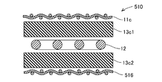
- first laminated body preparing step By preparing a first laminated body in which the first insulating layer 513a, the heater 12, and the second insulating layer 513b are laminated in this order (first laminated body preparing step), and heating and pressurizing the first laminated body, The first molded body is molded (first molded body molding step).
- stacked the 1st electrode sheet 11c, the said 1st molded object, and the 2nd electrode sheet 516 in order was prepared (2nd laminated body preparation process), and the said 2nd laminated body was heated and added.
- the electrostatic sheet 510 of the transducer 500 is manufactured (heating and pressing step).
- the heater 12 is sandwiched between the first electrode sheet 11c and the second electrode sheet 516. Therefore, the thickness of the electrostatic sheet 510 can be reduced. Therefore, a small electrostatic sheet 510 can be manufactured.
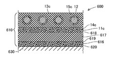
- the transducer 600 includes a base material 630 and an electrostatic sheet 610 attached to an attachment surface of the base material 630.
- the heater 12 is arranged on the back surface side of the second electrode sheet 11c, whereas in the electrostatic sheet 610 of the present example, the heater 12 is arranged on the first electrode sheet 11c. They are different in that they are arranged on the surface side of.
- the electrostatic sheet 610 of this example has a heater function and is flexible as a whole. Further, the electrostatic sheet 610 has a configuration using the electrostatic sheet 10c of the fifth example. In this example, parts having the same configurations as those of the electrostatic sheet 10c of the fifth example are designated by the same reference numerals, and detailed description thereof will be omitted.
- the electrostatic sheet 610 includes at least the heater 12, the first electrode sheet 11c, the second electrode sheet 616, the surface-side insulating layer 13c, the inter-electrode insulating layer 617, the heater fusion layer 15c, the surface-side fusion layer 14c, and the inter-electrode space.
- the first fusion bonding layer 618 and the inter-electrode second fusion bonding layer 619 are provided.
- the electrostatic sheet 610 further includes a base material fusion bonding layer 620.
- the heater 12 is arranged on the surface side.
- the heater 12 corresponds to a portion that functions as the heater 12 in the electrostatic sheet 10c of the fifth example.
- the first electrode sheet 11c is arranged to face the back surface of the heater 12.
- the first electrode sheet 11c corresponds to a portion that functions as the electrode sheet 11c in the electrostatic sheet 10c of the fifth example.
- the second electrode sheet 616 is arranged to face the back surface of the first electrode sheet 11c.
- the second electrode sheet 616 has the same configuration as the first electrode sheet 11c.
- the front-side insulating layer 13c is formed in a sheet shape and is sandwiched between the heater 12 and the first electrode sheet 11c.
- the front surface side insulating layer 13c corresponds to a portion functioning as the insulating layer 13c in the electrostatic sheet 10c of the fifth example.
- the inter-electrode insulating layer 617 is formed in a sheet shape and is sandwiched between the first electrode sheet 11c and the second electrode sheet 616.
- the inter-electrode insulating layer 617 is made of an elastically deformable material.
- the inter-electrode insulating layer 617 is formed of, for example, a thermoplastic material, particularly a thermoplastic elastomer.
- the inter-electrode insulating layer 617 may be formed of a non-thermoplastic elastomer foam material, a non-woven fabric, or the like.
- the interelectrode insulating layer 617 functions as a dielectric layer in the electrostatic sheet.
- the surface-side insulating layer 13c and the inter-electrode insulating layer 617 are made of different materials.
- the surface-side insulating layer 13c is made of a material having a higher thermal conductivity than the interelectrode insulating layer 617.
- the interelectrode insulating layer 617 does not need to be a material having high thermal conductivity. By forming the interelectrode insulating layer 617 from a material that effectively exhibits a dielectric, the detection performance or drive performance of the electrostatic sheet 610 can be improved.
- the heater fusing layer 15c is made of a fusing material, and joins the heater 12 and the front side insulating layer 13c.
- the heater fusing layer 15c corresponds to a portion that functions as the heater fusing layer 15c in the electrostatic sheet 10c of the fifth example.
- the heater 12 is joined to the first electrode sheet 11c by the heater fusion layer 15c while being embedded in the front-side insulating layer 13c on the front side.
- the front-side fusion layer 14c is formed of a fusion material, and joins the front-side insulating layer 13c and the first electrode sheet 11c.
- the front-side fusion-bonding layer 14c corresponds to a portion functioning as the electrode fusion-bonding layer 14c in the electrostatic sheet 10c of the fifth example.
- the first inter-electrode fusion layer 618 is made of a fusion material and joins the first electrode sheet 11c and the inter-electrode insulating layer 617.
- the inter-electrode first fusion-bonding layer 618 may be configured as a part of the inter-electrode insulating layer 617, or may be joined to the inter-electrode insulating layer 617 as a separate member.
- the inter-electrode first fusion-bonding layer 618 corresponds to the inter-electrode first fusion-bonding layer 418 in the transducer 400 of the fourth example.
- the inter-electrode second fusion-bonding layer 619 is made of a fusion-bonding material, and joins the inter-electrode insulating layer 617 and the second electrode sheet 616.
- the inter-electrode second fusion bonding layer 619 may be configured as a part of the inter-electrode insulating layer 617, or may be joined to the inter-electrode insulating layer 617 as a separate member.
- the inter-electrode second fusing layer 619 corresponds to the inter-electrode second fusing layer 419 in the transducer 400 of the fourth example.
- the base material fusion layer 620 is made of a fusion material, and joins the interelectrode insulating layer 617 and the mounting surface of the base material 630.
- the base material fusion bonding layer 620 may be configured as a part of the interelectrode insulating layer 617, or may be joined to the interelectrode insulating layer 617 as a separate member.
- the first material 13c1 of the front-side insulating layer 13c, the heater 12, the second material 13c2 of the front-side insulating layer 13c, the first electrode sheet 11c, the material 617a of the inter-electrode insulating layer 617, and the second electrode sheet 616 were laminated in this order.
- a laminated body is prepared (preparation process). Then, the laminated body is heated and pressed (heating and pressing step).
- the first material 13c1 and the second material 13c2 of the surface-side insulating layer 13c are softened to function as a fusion material and are bonded to the heater 12.
- the portion fused to the heater 12 becomes the heater fusion layer 15c.
- the first material 13c1 and the second material 13c2 of the front surface side insulating layer 13c are integrated to form the front surface side insulating layer 13c.
- the heater 12 is in a state of being embedded in the front insulating layer 13c.
- the material 617a of the inter-electrode insulating layer 617 softens and functions as a fusion material, and is bonded to the first electrode sheet 11c.
- the portion fused to the first electrode sheet 11c becomes the inter-electrode first fusion layer 618.
- the material 617a of the inter-electrode insulating layer 617 passes through the through hole of the first electrode sheet 11c and moves to the surface layer side of the first electrode sheet 11c. Then, the material 617a that has moved to the front surface side of the first electrode sheet 11c is joined to the second material 13c2 of the front surface side insulating layer 13c.
- the second material 13c2 of the surface-side insulating layer 13c softens and functions as a fusion material, and is bonded to the surface side of the first electrode sheet 11c. That is, a part of the material 617a of the inter-electrode insulating layer 617 and a part of the second material 13c2 of the surface-side insulating layer 13c become the surface-side fusion bonding layer 14c.
- the material 617a of the inter-electrode insulating layer 617 softens and functions as a fusion material, and is bonded to the second electrode sheet 616.
- the portion fused to the second electrode sheet 616 becomes the inter-electrode second fused layer 619.
- the material 617a of the inter-electrode insulating layer 617 passes through the through hole of the second electrode sheet 616 and moves to the back surface side of the second electrode sheet 616.
- the material 617a that has moved to the back surface side of the second electrode sheet 616 is joined to the back surface side of the second electrode sheet 616. That is, the material 617a of the inter-electrode insulating layer 617 becomes the base material fusion layer 620. In this way, the electrostatic sheet 610 of the transducer 600 is manufactured.
- the base material fusion layer 620 is heated by applying pressure to the base material 630 while heating the base material fusion layer 620. 620 is fused to the substrate 630. In this way, the transducer 600 is manufactured.
- a first laminated body in which the first electrode sheet 11c, the material 617a of the inter-electrode insulating layer 617, and the second electrode sheet 616 are laminated in this order is prepared (first laminated body preparing step), and the first laminated body is heated and heated. By pressing, the first molded body is molded (first molded body molding step).
- second laminated body preparing step a second laminated body in which the first material 13c1 of the front surface side insulating layer 13c, the heater 12, and the second material 13c2 of the front surface side insulating layer 13c are laminated in this order is prepared (second laminated body preparing step), and the second The second molded body is molded by heating and pressing the laminated body (second molded body molding step).
- the final laminated body in which the first molded body and the second molded body are laminated is prepared (final laminated body preparing step), and the final laminated body is heated and pressed to manufacture the electrostatic sheet 610 ( Final heat and pressure step).
- the heater 12 is arranged on the surface layer. Therefore, the transducer 600 can have a high heater function.
- the transducer 600 can have a high heater function.
- by using different materials for the surface-side insulating layer 13c and the inter-electrode insulating layer 617 it is possible to achieve both a high heater function and high detection performance or drive performance.
Landscapes
- Chemical & Material Sciences (AREA)
- Engineering & Computer Science (AREA)
- Ceramic Engineering (AREA)
- Surface Heating Bodies (AREA)
- Control Of Resistance Heating (AREA)
Abstract
揮散型接着剤および有機溶媒を用いることなく製造でき、かつ、製造工数の低減を図ることができるヒータ機能を有する静電型トランスデューサを提供する。静電型トランスデューサ(1)は、電極シート(11)と、シート状に形成され電極シート(11)に対向して配置されたヒータ(12)と、シート状に形成され電極シート(11)とヒータ(12)との間に挟まれた絶縁層(13)と、融着材料により形成されており、電極シート(11)および絶縁層(13)の少なくとも一方の一部分として構成され若しくは電極シート(11)および絶縁層(13)に別部材として接合され、自身の融着により電極シート(11)と絶縁層(13)とを接合する電極融着層(14)とを備える。
Description
本発明は、静電型トランスデューサおよびその製造方法に関するものである。
近年、ヒータ機能を有する静電型トランスデューサが知られている。例えば、特許文献1、2には、運転者の手を放していることを検出する静電センサと、ヒータとを備えるステアリングホイールが記載されている。特許文献1に記載のステアリングホイールは、ステアリングホイールの軸芯の外周側にヒータ線をコイル状に周回し、ヒータ線の外周側に静電センサを配置することにより製造される。
特許文献1に記載の製造方法のように、ステアリングホイールの軸芯等の基材に、ヒータ線を取り付け、その後に静電シートを取り付ける製造方法では、多大な製造工数を要する。すなわち、ヒータ線の取付工程と、静電シートの取付工程とが必要となる。さらに、ヒータ線および静電シートを取り付ける基材取付面が、ステアリングホイールの軸芯のように湾曲した面である場合等、単なる平面ではなく複雑な形状である場合には、上記2工程を有することにより多大な製造工数を要する。そこで、製造工数を低減することが求められる。
また、トランスデューサが、可撓性を有する基材と、当該基材に取り付けられたヒータと、静電センサとを備える場合にも、製造工数の低減を図ることが求められる。また、トランスデューサが、基材を備えずに、ヒータと静電センサとを備える構成とする場合においても、製造工数の低減を図ることが求められる。
また、近年、環境対策として、揮発性有機化合物(VOC)の排出の抑制が求められている。そのため、揮散型接着剤を用いないことが求められ、かつ、有機溶媒も用いないことが求められる。
本発明は、揮散型接着剤および有機溶媒を用いることなく製造でき、かつ、製造工数の低減を図ることができるヒータ機能を有する静電型トランスデューサ、および、その製造方法を提供することを目的の一つとする。
(1.静電型トランスデューサ)
本発明の実施形態に係るヒータ機能を有する静電型トランスデューサは、電極シートと、シート状に形成され前記電極シートに対向して配置されたヒータと、シート状に形成され前記電極シートと前記ヒータとの間に挟まれた絶縁層と、融着材料により形成されており、前記電極シートおよび前記絶縁層の少なくとも一方の一部分として構成され若しくは前記電極シートおよび前記絶縁層に別部材として接合され、自身の融着により前記電極シートと前記絶縁層とを接合する電極融着層とを備える。
本発明の実施形態に係るヒータ機能を有する静電型トランスデューサは、電極シートと、シート状に形成され前記電極シートに対向して配置されたヒータと、シート状に形成され前記電極シートと前記ヒータとの間に挟まれた絶縁層と、融着材料により形成されており、前記電極シートおよび前記絶縁層の少なくとも一方の一部分として構成され若しくは前記電極シートおよび前記絶縁層に別部材として接合され、自身の融着により前記電極シートと前記絶縁層とを接合する電極融着層とを備える。
ヒータ機能を有する静電型トランスデューサの上記各構成部材がシート状に形成されているため、静電型トランスデューサを構成する電極シート、絶縁層およびヒータは、全体としてシート状に一体に形成されている。従って、静電型トランスデューサが、基材を備える場合であっても、基材を備えない場合であっても、静電型トランスデューサの製造工数の低減を図ることができる。
また、ヒータ機能を有する静電型トランスデューサの上記構成部材は一体に形成されているため、当該静電型トランスデューサの上記構成部材を基材の取付面に取り付ける場合において、取付面への取付工程を1工程とすることができる。従って、製造工数を低減することができる。また、取付面に対して1工程での取付工程とすることができるため、取付面が複雑な形状であるほど、より製造工数の低減に効果を発揮する。可撓性を有する基材に当該静電型トランスデューサの上記構成部材を取り付ける場合にも、製造工数の低減を図ることができる。
(2.静電型トランスデューサの製造方法)
本発明に係るヒータ機能を有する静電型トランスデューサの製造方法は、少なくとも前記電極シート、前記絶縁層、および、前記ヒータを含む積層体を、加熱および加圧することにより、前記静電型トランスデューサを製造する。つまり、電極シートと絶縁層とは、加熱および加圧によって融着する融着材料により接合される。従って、揮散型接着剤および有機溶媒を用いることなく、ヒータ機能を有する静電型トランスデューサを製造することができる。つまり、環境に優しい静電型トランスデューサを製造することができる。
本発明に係るヒータ機能を有する静電型トランスデューサの製造方法は、少なくとも前記電極シート、前記絶縁層、および、前記ヒータを含む積層体を、加熱および加圧することにより、前記静電型トランスデューサを製造する。つまり、電極シートと絶縁層とは、加熱および加圧によって融着する融着材料により接合される。従って、揮散型接着剤および有機溶媒を用いることなく、ヒータ機能を有する静電型トランスデューサを製造することができる。つまり、環境に優しい静電型トランスデューサを製造することができる。
(1.適用対象)
静電型トランスデューサ(以下、「トランスデューサ」と称する)は、ヒータ機能を有する静電シートを備える。トランスデューサは、例えば、基材と、基材の取付面に取り付けられた当該静電シートとを備える。基材は、任意の部材であって、金属、樹脂、その他の材料により形成されている。
静電型トランスデューサ(以下、「トランスデューサ」と称する)は、ヒータ機能を有する静電シートを備える。トランスデューサは、例えば、基材と、基材の取付面に取り付けられた当該静電シートとを備える。基材は、任意の部材であって、金属、樹脂、その他の材料により形成されている。
また、基材の取付面は、曲面、複合平面(複数の平面により形成された形状)、平面と曲面の複合形状等の三次元形状に形成してもよいし、基材の表面が単一平面形状に形成してもよい。基材が可撓性を有する材料により形成されている場合に、当該基材の取付面に当該静電シートを取り付けることもできる。また、トランスデューサは、基材を備えることなく、当該静電シート単体として利用することもできる。
静電シートは、基材の取付面(表面)に配置されている。静電シートは、全体として、柔軟である。柔軟とは、可撓性を有し、且つ、面方向に伸張可能であることを意味する。従って、基材の取付面が三次元形状であったとしても、静電シートは、基材の取付面に沿って取り付けることができる。特に、静電シートを面方向に伸張させながら基材の取付面に取り付けることで、静電シートにしわが発生することを抑制することができる。
静電シートは、一対の電極間の静電容量の変化を利用して、アクチュエータまたはセンサとして機能させることができる。静電シートは、一対の電極のうち少なくとも1つを備えればよく、一対の電極を備える構成に限定されるものではない。もちろん、静電シートは、一対の電極を備えるようにしてもよい。
静電シートは、電極間の静電容量の変化を利用して、振動や音等を発生させるアクチュエータとして機能させることができる。また、静電シートは、電極間の静電容量の変化を利用して、外部からの押込力等を検出するセンサ、電位を有する導電体の接触または接近を検出するセンサとして機能させることができる。
静電シートがアクチュエータとして機能する場合には、電極に電圧が印加されることにより、電極間の電位に応じて誘電体が変形し、誘電体の変形に伴って振動が発生する。静電シートが押込力を検出するセンサとして機能する場合には、外部からの押込力、振動、および、音等(以下、外部からの押込力等)の入力に起因して誘電体が変形することにより電極間の静電容量が変化し、電極間の静電容量に応じた電圧を検出することで、外部からの押込力等を検出する。また、静電シートが接触または接近を検出するセンサとして機能する場合には、電位を有する導電体の接触または接近により、電極間の静電容量が変化し、変化した電極間の静電容量に応じた電圧を検出することで、当該導電体の接触または接近を検出する。
トランスデューサは、例えば、ポインティングデバイスであるマウスやジョイスティックの表面、車両部品の表面等に適用できる。車両部品としては、ステアリングホイール、ドアノブ、シフトレバー、アームレスト、ドアトリム、センタートリム、センターコンソール等が含まれる。多くの場合には、基材は、金属や樹脂等の可撓性を有しない材料により形成されている。つまり、トランスデューサは、対象者の状態(操作等)の検出や対象者への振動の付与に加えて、対象者への熱の付与を行うことができる。
また、トランスデューサは、シート座面の表層側または背もたれ面の表層側に配置されるようにしてもよい。この場合、トランスデューサは、樹脂フィルム等の可撓性を有する材料により形成された基材に、ヒータ機能を有する静電シートを取り付けるように構成してもよい。また、トランスデューサは、基材を備えずに、ヒータ機能を有する静電シートにより構成されるようにしてもよい。
(2.トランスデューサ1の基本構成)
トランスデューサ1の基本構成の一例について、図1および図2を参照して説明する。トランスデューサ1は、図1に示すように、ヒータ機能を有する静電シート10を備える。静電シート10は、全体として、シート状に形成されており、かつ、柔軟である。ここで、柔軟とは、可撓性を有し、且つ、面方向に伸張可能であることを意味する。
トランスデューサ1の基本構成の一例について、図1および図2を参照して説明する。トランスデューサ1は、図1に示すように、ヒータ機能を有する静電シート10を備える。静電シート10は、全体として、シート状に形成されており、かつ、柔軟である。ここで、柔軟とは、可撓性を有し、且つ、面方向に伸張可能であることを意味する。
静電シート10は、上述した基材(図1には図示しない)の取付面に取り付けられている。静電シート10は、図1に示すように、少なくとも、電極シート11、ヒータ12、絶縁層13を備える。静電シート10は、電極シート11、ヒータ12、および、絶縁層13以外の構成を備えるようにしてもよい。
電極シート11は、導電性を有する。さらに、電極シート11は、柔軟である。電極シート11は、例えば、導電性エラストマー、導電性布、または、金属箔等により形成されている。
電極シート11が導電性エラストマーにより形成される場合について詳細に説明する。この場合、電極シート11は、導電性フィラーを含むエラストマーにより形成されている。つまり、電極シート11は、エラストマーを母材として、導電性フィラーを含有させることにより形成される。
電極シート11は、例えば、熱可塑性エラストマーにより形成されている。電極シート11は、熱可塑性エラストマー自身により形成されるようにしてもよいし、熱可塑性エラストマーを素材として加熱することによって架橋されたエラストマーにより形成されるようにしてもよい。
ここで、電極シート11は、スチレン系、オレフィン系、塩ビ系、ウレタン系、エステル系、アミド系等のエラストマーから、1種以上を選択可能である。例えば、スチレン系エラストマーとしては、SBS、SEBS、SEPS等が挙げられる。オレフィン系エラストマーとしては、EEA、EMA、EMMA等の他、エチレンとαオレフィンとの共重合体(エチレン-オクテン共重合体)等が挙げられる。
電極シート11は、熱可塑性エラストマー以外のゴム、樹脂を含んでいてもよい。例えば、エチレン-プロピレンゴム(EPM、EPDM)等のゴムを含む場合には、電極シート11の柔軟性が向上する。電極シート11の柔軟性を向上させるという観点から、電極シート11に可塑剤等の柔軟性付与成分を含有させてもよい。
また、電極シート11が導電性布により形成される場合について詳細に説明する。導電性布とは、導電性繊維により形成された織物または不織布である。ここで、導電性繊維は、柔軟性を有する繊維の表面を導電性材料により被覆することにより形成される。導電性繊維は、例えば、ポリエチレン等の樹脂繊維の表面に、銅やニッケル等をメッキすることにより形成される。
電極シート11が金属箔により形成される場合について詳細に説明する。金属箔は、導電性布と同様に、複数の貫通孔を有する。従って、電極シート11は、可撓性を有し、貫通孔の変形に伴い面方向への伸張を可能とする。金属箔は、導通可能な金属材料であればよく、例えば、銅箔、アルミニウム箔等を適用できる。
ヒータ12は、図2に示すように、ヒータ線によってシート状(面状)に形成されている。ヒータ12は、電極シート11の一方の面に対向して配置されている。ヒータ線は、金属の合金系材料であり、例えば、ニッケルクロム、鉄クロム等が適用される。
絶縁層13は、シート状に形成され、少なくとも、電極シート11とヒータ12との間に挟まれている。絶縁層13は、ヒータ12の両面(図1の上下面)を覆うように形成してもよい。なお、図1においては、絶縁層13は、ヒータ12の両面を覆う場合を図示している。
絶縁層13は、柔軟な材料により形成されている。絶縁層13は、例えば、熱可塑性材料、特に熱可塑性エラストマーにより形成されている。また、絶縁層13は、非熱可塑性エラストマーの発泡材料、不織布または織物等を用いることもできる。絶縁層13は、静電シート10における誘電層としても機能させることが可能である。
静電シート10は、さらに、電極融着層14を備える。電極融着層14は、融着材料により形成されている。電極融着層14は、電極融着層14自身の融着(熱融着)により、電極シート11と絶縁層13とを接合する。ここで、電極融着層14は、電極シート11の一部分として構成されるようにしてもよいし、絶縁層13の一部分として構成されるようにしてもよい。さらに、電極融着層14は、電極シート11の一部分として構成され、かつ、絶縁層13の一部分として構成されるようにしてもよい。また、電極融着層14は、電極シート11および絶縁層13と別部材として接合されるようにしてもよい。
上述したトランスデューサ1の基本構成の製造方法について説明する。静電シート10の構成要素である、電極シート11、絶縁層13、ヒータ12の順に積層された積層体を準備する(準備工程)。ここで、当該時点において、絶縁層13は、ヒータ12に予め一体に形成されていてもよいし、電極シート11およびヒータ12とは別体にされていてもよい。
続いて、当該積層体を加熱および加圧する(加熱加圧工程)。そうすると、電極融着層14によって、電極シート11と絶縁層13とが接合される。電極融着層14は、上述したように、電極シート11の一部分、絶縁層13の一部分、または、電極シート11および絶縁層13とは別材料の何れかである。このようにして、静電シート10が製造される。続いて、静電シート10を、図示しない基材に取り付ける。基材が存在しない場合には、静電シート10の製造により、トランスデューサ1が完成する。
(3.トランスデューサ1の基本構成による効果)
トランスデューサ1を構成する静電シート10は、全体としてシート状に一体に形成されている。従って、トランスデューサ1が、基材を備える場合であっても、基材を備えない場合であっても、トランスデューサ1の製造工数の低減を図ることができる。
トランスデューサ1を構成する静電シート10は、全体としてシート状に一体に形成されている。従って、トランスデューサ1が、基材を備える場合であっても、基材を備えない場合であっても、トランスデューサ1の製造工数の低減を図ることができる。
また、トランスデューサ1の上記構成部材11,12,13は一体に形成されているため、当該トランスデューサ1の上記構成部材11,12,13を基材の取付面に取り付ける場合において、取付面への取付工程を1工程とすることができる。従って、製造工数を低減することができる。また、取付面に対して1工程での取付工程とすることができるため、取付面が複雑な形状であるほど、より製造工数の低減に効果を発揮する。可撓性を有する基材に当該トランスデューサ1の上記構成部材11,12,13を取り付ける場合にも、製造工数の低減を図ることができる。
さらに、電極シート11と絶縁層13との接合は、熱によって軟化可能な融着材料により行われている。従って、揮散型接着剤および有機溶媒を用いることなく、ヒータ機能を有する静電シート10を製造することができる。つまり、環境に優しいトランスデューサ1を製造することができる。
また、電極融着層14が、電極シート11の一部分または絶縁層13の一部分により構成される場合には、電極融着層14として専用の部材を必要としない。その結果、より低コスト化を図ることができる。
(4.静電シート10の例)
上述したトランスデューサ1の基本構成の静電シート10について、複数例をあげて説明する。
上述したトランスデューサ1の基本構成の静電シート10について、複数例をあげて説明する。
(4-1.第一例の静電シート10a)
第一例の静電シート10aの構成について、図3および図4を参照して説明する。静電シート10aを構成する電極シート11aは、熱可塑性材料を含んで形成されている。例えば、電極シート11aは、熱可塑性エラストマーにより形成されている。つまり、電極シート11aは、加熱および加圧により、軟化して、相手部材に融着することが可能である。
第一例の静電シート10aの構成について、図3および図4を参照して説明する。静電シート10aを構成する電極シート11aは、熱可塑性材料を含んで形成されている。例えば、電極シート11aは、熱可塑性エラストマーにより形成されている。つまり、電極シート11aは、加熱および加圧により、軟化して、相手部材に融着することが可能である。
絶縁層13aは、熱可塑性材料、例えば、熱可塑性エラストマーにより形成されている。絶縁層13aの熱可塑性材料は、電極シート11aの熱可塑性材料よりも軟化点の高い材料である。さらに、絶縁層13aは、図3に示すように、電極シート11aとの接合面に凹凸を有している。例えば、絶縁層13aを成形するための金型に凹凸面を形成しておくことで、絶縁層13aにおける電極シート11aとの接合面に凹凸を形成することができる。
図4に示すように、電極シート11aと絶縁層13aとを積層して、当該積層体に加熱および加圧することにより、静電シート10aが製造される。ここで、電極シート11aは、絶縁層13aよりも軟化点の低い熱可塑性材料により形成されている。従って、積層体に加熱および加圧されることにより、電極シート11aの熱可塑性材料が、先に軟化して、絶縁層13aの凹部に入り込む。
そして、電極シート11aの一部分が、自身の融着により、電極シート11aと絶縁層13aの凹凸面とを接合する電極融着層14として機能する。特に、電極シート11aの一部分が、絶縁層13aの凹部に入り込むことにより、アンカー効果を発揮し、電極シート11aと絶縁層13aとの接合力が増加する。
(4-2.第二例の静電シート10a)
上記第一例の静電シート10aにおいて、絶縁層13aは、熱可塑性材料としたが、非熱可塑性材料を適用することもできる。この場合、積層体を加熱および加圧した場合において、当然に、電極シート11aの熱可塑性材料は、絶縁層13aよりも先に軟化することになる。
上記第一例の静電シート10aにおいて、絶縁層13aは、熱可塑性材料としたが、非熱可塑性材料を適用することもできる。この場合、積層体を加熱および加圧した場合において、当然に、電極シート11aの熱可塑性材料は、絶縁層13aよりも先に軟化することになる。
(4-3.第三例の静電シート10a)
絶縁層13aは、非熱可塑性材料の繊維により形成された不織布または織物である。不織布または織物は、繊維により形成されているため、少なくとも、絶縁層13aにおいて電極シート11aとの接合面に、図3に示すように、凹凸を有する。詳細には、絶縁層13aの当該接合面において、繊維と、繊維間の空間により形成された凹凸を有している。つまり、絶縁層13aは、繊維を凸部とし、隣り合う繊維の間を凹部とする凹凸面を有する。
絶縁層13aは、非熱可塑性材料の繊維により形成された不織布または織物である。不織布または織物は、繊維により形成されているため、少なくとも、絶縁層13aにおいて電極シート11aとの接合面に、図3に示すように、凹凸を有する。詳細には、絶縁層13aの当該接合面において、繊維と、繊維間の空間により形成された凹凸を有している。つまり、絶縁層13aは、繊維を凸部とし、隣り合う繊維の間を凹部とする凹凸面を有する。
そして、第一例と同様に、図4に示すように、電極シート11aと絶縁層13aとを積層して、当該積層体を加熱および加圧することにより、静電シート10aが製造される。つまり、積層体が加熱および加圧されることにより、電極シート11aの熱可塑性材料が、軟化して、絶縁層13aの凹部に入り込む。そして、電極シート11aの一部分が、自身の融着により、電極シート11aと絶縁層13aの凹凸面とを接合する電極融着層14として機能する。
(4-4.第四例の静電シート10b)
第四例の静電シート10bの構成について、図5および図6を参照して説明する。静電シート10bを構成する電極シート11aは、第一例と同様に、熱可塑性材料を含んで形成されている。
第四例の静電シート10bの構成について、図5および図6を参照して説明する。静電シート10bを構成する電極シート11aは、第一例と同様に、熱可塑性材料を含んで形成されている。
絶縁層13bは、非熱可塑性の発泡材料により形成されている。図5に示すように、絶縁層13bは、少なくとも表面に気泡により形成された凹凸を有している。もちろん、絶縁層13bは、内部においては、凹部(気泡)を有している。
そして、第一例と同様に、図6に示すように、電極シート11aと絶縁層13bとを積層して、当該積層体を加熱および加圧することにより、静電シート10aが製造される。つまり、積層体が加熱および加圧されることにより、電極シート11aの熱可塑性材料が、軟化して、絶縁層13bの凹部に入り込む。そして、電極シート11aの一部分が、自身の融着により、電極シート11aと絶縁層13bの凹凸面とを接合する電極融着層14として機能する。
(4-5.第五例の静電シート10c)
第五例の静電シート10cの構成について図7および図8を参照して説明する。静電シート10は、図7に示すように、少なくとも、電極シート11c、ヒータ12、絶縁層13c、電極融着層14c、および、ヒータ融着層15cを備える。電極シート11cは、導電性を有しつつ、柔軟性および面方向への伸縮性を有する。図8に示すように、電極シート11cは、例えば、導電性布である。
第五例の静電シート10cの構成について図7および図8を参照して説明する。静電シート10は、図7に示すように、少なくとも、電極シート11c、ヒータ12、絶縁層13c、電極融着層14c、および、ヒータ融着層15cを備える。電極シート11cは、導電性を有しつつ、柔軟性および面方向への伸縮性を有する。図8に示すように、電極シート11cは、例えば、導電性布である。
絶縁層13cは、例えば、熱可塑性材料、特に熱可塑性エラストマーにより形成されている。電極融着層14cは、絶縁層13cの一部分として構成されるようにしてもよいし、絶縁層13cに別部材として接合されるようにしてもよい。
ヒータ融着層15cは、融着材料により形成されている。ヒータ融着層15cは、ヒータ融着層15c自身の融着(熱融着)により、ヒータ12と絶縁層13cとを接合する。特に、ヒータ12は、絶縁層13cに埋設された状態で、ヒータ融着層15cにより接合されている。ヒータ融着層15cは、絶縁層13cの一部分として構成されるようにしてもよいし、絶縁層13cに別部材として接合されるようにしてもよい。
例えば、ヒータ融着層15cは、融着材料である熱可塑性材料により形成されており、絶縁層13cの一部分として構成される。この場合、絶縁層13cの一部分としてのヒータ融着層15cは、自身の融着によって、ヒータ12と絶縁層13cとを接合する。
静電シート10cの製造方法について、図9を参照して説明する。ここでは、絶縁層13cの素材が、熱可塑性材料により形成されているものとする。電極シート11c、絶縁層13cの第一素材13c1、ヒータ12、および、絶縁層13cの第二素材13c2の順に積層された積層体を準備する(準備工程)。続いて、積層体を加熱および加圧する(加熱加圧工程)。そうすると、絶縁層13cの第一素材13c1が、軟化して融着材料として機能し、電極シート11cに接合する。電極シート11cに融着した部位が、電極融着層14cとなる。
また、絶縁層13cの第一素材13c1および第二素材13c2が、軟化して融着材料として機能し、ヒータ12に接合する。ヒータ12に融着した部位が、ヒータ融着層15cとなる。そして、絶縁層13cの第一素材13c1と第二素材13c2とが一体化されることにより、絶縁層13cを形成する。さらに、ヒータ12が絶縁層13cに埋設された状態となる。このようにして、トランスデューサ1の静電シート10cが製造される。
絶縁層13cが熱可塑性材料により形成され、電極融着層14cおよびヒータ融着層15cが絶縁層13cの一部分として構成されている。従って、電極融着層14cおよびヒータ融着層15cとして専用の部材を必要としない。その結果、より低コスト化を図ることができる。
また、電極融着層14cおよびヒータ融着層15cが、絶縁層13cとは別部材として配置される場合には、電極シート11c、電極融着層14cの素材、絶縁層13c、ヒータ融着層15cの素材、および、ヒータ12の順に積層された積層体を準備する(準備工程)。続いて、積層体を加熱および加圧する(加熱加圧工程)。そうすると、電極融着層14cの素材が、軟化して融着材料として機能し、電極シート11cと絶縁層13cとを接合する。また、ヒータ融着層15cの素材が、軟化して融着材料として機能し、ヒータ12と絶縁層13cとを接合する。
(5.トランスデューサ1の例)
上述したトランスデューサ1の基本構成を有しつつ、他の要素を備えるトランスデューサ1について、複数例をあげて説明する。特に、トランスデューサ1の静電シート10は、一対の電極シートを有する構成である。
上述したトランスデューサ1の基本構成を有しつつ、他の要素を備えるトランスデューサ1について、複数例をあげて説明する。特に、トランスデューサ1の静電シート10は、一対の電極シートを有する構成である。
(5-1.第一例のトランスデューサ100)
第一例のトランスデューサ100の構成について図10を参照して説明する。トランスデューサ100は、ヒータ機能を有する静電シート110を備える。静電シート110は、全体として、柔軟である。静電シート110は、第一例乃至第四例の何れか1つの静電シート10a,10bを利用した構成をなしている。本例において、静電シート10a,10bと同一構成の部分については、同一符号を付して詳細な説明を省略する。
第一例のトランスデューサ100の構成について図10を参照して説明する。トランスデューサ100は、ヒータ機能を有する静電シート110を備える。静電シート110は、全体として、柔軟である。静電シート110は、第一例乃至第四例の何れか1つの静電シート10a,10bを利用した構成をなしている。本例において、静電シート10a,10bと同一構成の部分については、同一符号を付して詳細な説明を省略する。
静電シート110は、少なくとも、第一電極シート116、第二電極シート11a、ヒータ12、電極間絶縁層117、裏面側絶縁層13a,13b、裏面側融着層14a,14bを備える。第一電極シート116は、第一例乃至第四例の何れか1つの静電シート10a,10bにおける電極シート11aと同様の構成を有する。第一電極シート116は、表層側に配置されている。
第二電極シート11aは、第一例乃至第四例の何れか1つの静電シート10a,10bにおける電極シート11aとして機能する部位に対応する。第二電極シート11aは、第一電極シート116の裏面に対向して配置されている。ヒータ12は、第一例乃至第四例の何れか1つの静電シート10a,10bにおけるヒータ12として機能する部位に対応する。ヒータ12は、第二電極シート11aの裏面に対向して配置されている。
電極間絶縁層117は、シート状に形成され、第一電極シート116と第二電極シート11aとの間に挟まれている。電極間絶縁層117は、弾性変形可能な材料により形成されている。電極間絶縁層117は、例えば、熱可塑性材料、特に熱可塑性エラストマーにより形成されている。また、電極間絶縁層117は、非熱可塑性エラストマーの発泡材料、不織布等を用いることもできる。電極間絶縁層117は、静電シートにおける誘電層として機能する。
裏面側絶縁層13a,13bは、シート状に形成され、第二電極シート11aとヒータ12との間に挟まれている。裏面側絶縁層13a,13bは、第一例乃至第四例の何れか1つの静電シート10a,10bにおける絶縁層13a,13bとして機能する部位に対応する。裏面側絶縁層13a,13bは、電極間絶縁層117と同種の材料により形成されている。両者が同種の材料により形成されることで、低コスト化を図ることができる。
裏面側融着層14a,14bは、融着材料により形成されている。裏面側融着層14a,14bは、第二電極シート11aと裏面側絶縁層13a,13bとを接合し、第一例の静電シート10a,10bにおける電極融着層14a,14bとして機能する部位に対応する。
第一例のトランスデューサ100の製造方法について説明する。第一電極シート116、電極間絶縁層117および第二電極シート11aは、予め積層された状態で一体に形成しておく(準備工程)。さらに、ヒータ12および裏面側絶縁層13a,13bは、予め一体に形成しておく(準備工程)。そして、それぞれ一体に形成された部材を積層した積層体を準備する(準備工程)。
続いて、積層体を加熱および加圧する(加熱加圧工程)。そうすると、第二電極シート11aが軟化して、裏面側絶縁層13a,13bの凹凸面に融着する。つまり、第二電極シート11aの一部分が、裏面側融着層14a,14bを形成する。このようにして、第一例のトランスデューサ100の静電シート110が製造される。
第一例のトランスデューサ100によれば、第一電極シート116、第二電極シート11a、および、電極間絶縁層117が、ヒータ12よりも表面側に位置している。つまり、ヒータ12が、第一電極シート116と第二電極シート11aとの間、および、第一電極シート116よりも表面側に位置していない。その結果、ヒータ12が検出性能または駆動性能に影響を及ぼすことを抑制できるため、高い検出性能または駆動性能を発揮することができる。
ヒータ12が、第二電極シート11aの裏面側に位置するとしても、電極間絶縁層117が熱伝導性の良好な材料とすることで、十分にヒータとしての機能を発揮することができる。ここで、ヒータ12に直接接触する裏面側絶縁層13a,13bが熱伝導性の良好な材料により形成されると、十分に熱が高くなる前に熱が拡散することによって、十分な熱が表層に伝達されにくい。そこで、裏面側絶縁層13a,13bをある程度熱伝導性の良好ではない材料とすることで、効果的に熱を表層に伝達させることができる。特に、裏面側絶縁層13a,13bが、内部に空孔が形成される発泡材料、不織布または織物等とすることで、より効果的に熱を表層に伝達させることができる。
(5-2.第二例のトランスデューサ200)
第二例のトランスデューサ200の構成について図11を参照して説明する。トランスデューサ200は、ヒータ機能を有する静電シート210を備える。静電シート110は、全体として、柔軟である。静電シート210は、第一例乃至第四例の何れか1つの静電シート10a,10bを利用した構成をなしている。本例において、静電シート10a,10bと同一構成の部分については、同一符号を付して詳細な説明を省略する。
第二例のトランスデューサ200の構成について図11を参照して説明する。トランスデューサ200は、ヒータ機能を有する静電シート210を備える。静電シート110は、全体として、柔軟である。静電シート210は、第一例乃至第四例の何れか1つの静電シート10a,10bを利用した構成をなしている。本例において、静電シート10a,10bと同一構成の部分については、同一符号を付して詳細な説明を省略する。
静電シート210は、少なくとも、第一電極シート11a、ヒータ12、第二電極シート216、第一絶縁層213a(13a,13b)、第二絶縁層213b(13a,13b)、第一電極融着層14a,14b、第二電極融着層217を備える。
第一電極シート11aは、第一例乃至第四例の何れか1つの静電シート10a,10bにおける電極シート11aと同様の構成を有する。第一電極シート11aは、表層側に配置されている。ヒータ12は、第一電極シート11aの裏面に対向して配置されている。
第二電極シート216は、第一電極シート11aと同様の構成を有する。第二電極シート216は、ヒータ12の裏面側に対向して配置されている。つまり、第一電極シート11aと第二電極シート216との間に、ヒータ12が介在している。
第一絶縁層213aは、シート状に形成され、第一電極シート11aとヒータ12との間に挟まれている。第一絶縁層213aは、第一例乃至第四例の何れか1つの静電シート10a,10bにおける絶縁層13a,13bの一部分として機能する。第二絶縁層213bは、シート状に形成され、ヒータ12と第二電極シート216との間に挟まれている。第二絶縁層213bは、第一例乃至第四例の静電シート10a,10bにおける絶縁層13a,13bの他の一部分として機能する。つまり、第一絶縁層213aおよび第二絶縁層213bは、同種の材料により形成されている。
第一電極融着層14a,14bは、融着材料により形成されている。第一電極融着層14a,14bは、第一電極シート11aと第一絶縁層213aとを接合する。第一電極融着層14a,14bは、第一例乃至第四例の何れか1つの静電シート10a,10bにおける電極融着層14a,14bとして機能する。第二電極融着層217は、融着材料により形成されている。第二電極融着層217は、第二電極シート216と第二絶縁層213bとを接合する。第二電極融着層217は、第一電極融着層14a,14bと同様の構成を有する。
第二例のトランスデューサ200の製造方法について説明する。第一絶縁層213a、ヒータ12、第二絶縁層213bは、予め一体に形成しておく。そして、第一電極シート11a、上記一体成形品、第二電極シート216の順で積層した積層体を準備する(準備工程)。
続いて、積層体を加熱および加圧する(加熱加圧工程)。そうすると、第一電極シート11aが軟化して、第一絶縁層213aの凹凸面に融着する。つまり、第一電極シート11aの一部分が、第一電極融着層14a,14bを形成する。さらに、第二電極シート216が軟化して、第二絶縁層213bの凹凸面に融着する。つまり、第二電極シート216の一部分が、第二電極融着層217を形成する。このようにして、第二例のトランスデューサ200の静電シート210が製造される。
第二例のトランスデューサ200によれば、ヒータ12が第一電極シート11aと第二電極シート216との間に挟まれている。従って、静電シート210の厚みが薄くできる。従って、小型の静電シート210を製造することができる。
(5-3.第三例のトランスデューサ300)
第三例のトランスデューサ300の構成について図12を参照して説明する。トランスデューサ300は、ヒータ機能を有する静電シート310を備える。静電シート310は、全体として、柔軟である。静電シート310は、第一例乃至第四例の何れか1つの静電シート10a,10bを利用した構成をなしている。本例においては、静電シート10a,10bと同一構成の部分については、同一符号を付して詳細な説明を省略する。
第三例のトランスデューサ300の構成について図12を参照して説明する。トランスデューサ300は、ヒータ機能を有する静電シート310を備える。静電シート310は、全体として、柔軟である。静電シート310は、第一例乃至第四例の何れか1つの静電シート10a,10bを利用した構成をなしている。本例においては、静電シート10a,10bと同一構成の部分については、同一符号を付して詳細な説明を省略する。
静電シート310は、少なくとも、ヒータ12、第一電極シート11a、第二電極シート316、表面側絶縁層13a,13b、電極間絶縁層317、表面側融着層14a,14bを備える。第一電極シート11aは、第一例乃至第四例の何れか1つの静電シート10a,10bにおける電極シート11aと同様の構成を有する。第一電極シート116は、表層側に配置されている。
ヒータ12は、表層側に配置されている。ヒータ12は、第一例乃至第四例の何れか1つの静電シート10a,10bにおけるヒータ12として機能する部位に対応する。
第一電極シート11aは、ヒータ12の裏面に対向して配置されている。第一電極シート11aは、第一例乃至第四例の何れか1つの静電シート10a,10bにおける電極シート11aとして機能する部位に対応する。第二電極シート316は、第一電極シート11aの裏面に対向して配置されている。第二電極シート316は、第一電極シート11aと同様の構成を有する。
表面側絶縁層13a,13bは、シート状に形成され、ヒータ12と第一電極シート11aとの間に挟まれている。表面側絶縁層13a,13bは、第一例乃至第四例の何れか1つの静電シート10a,10bにおける絶縁層13a,13bとして機能する部位に対応する。
電極間絶縁層317は、シート状に形成され、第一電極シート11aと第二電極シート316との間に挟まれている。電極間絶縁層317は、弾性変形可能な材料により形成されている。電極間絶縁層317は、例えば、熱可塑性材料、特に熱可塑性エラストマーにより形成されている。また、電極間絶縁層317は、非熱可塑性エラストマーの発泡材料、不織布等を用いることもできる。電極間絶縁層317は、静電シートにおける誘電層として機能する。
ここで、表面側絶縁層13a,13bと電極間絶縁層317とは、異種の材料により形成されている。具体的には、表面側絶縁層13a,13bは、電極間絶縁層317よりも熱伝導率が高い材料により形成されている。ヒータ12から表層までの部位が、熱伝導率が高い材料により形成されることで、静電シート310の表層において、ヒータ機能を効果的に発揮することができる。一方、電極間絶縁層317は、熱伝導率が高い材料であることは不要である。そして、電極間絶縁層317が誘電体として効果的に発揮する材料により形成することにより、静電シート310による検出性能または駆動性能を高くすることができる。
第三例のトランスデューサ300の製造方法について説明する。第一電極シート11a、電極間絶縁層317および第二電極シート316は、予め積層された状態で一体に形成しておく(準備工程)。さらに、ヒータ12および表面側絶縁層13a,13bは、予め一体に形成しておく(準備工程)。そして、それぞれ一体に形成された部材を積層した積層体を準備する(準備工程)。
続いて、積層体を加熱および加圧する(加熱加圧工程)。そうすると、第一電極シート11aが軟化して、表面側絶縁層13a,13bの凹凸面に融着する。つまり、第一電極シート11aの一部分が、表面側融着層14a,14bを形成する。このようにして、第三例のトランスデューサ300の静電シート310が製造される。
(5-4.第四例のトランスデューサ400)
(5-4-1.第四例のトランスデューサ400の構成)
第四例のトランスデューサ400の構成について図13を参照して説明する。トランスデューサ400は、基材430と、基材430の取付面に取り付けられた静電シート410とを備える。
(5-4-1.第四例のトランスデューサ400の構成)
第四例のトランスデューサ400の構成について図13を参照して説明する。トランスデューサ400は、基材430と、基材430の取付面に取り付けられた静電シート410とを備える。
静電シート410は、ヒータ機能を有する。静電シート410は、全体として、柔軟である。静電シート410は、第五例の静電シート10cを利用した構成をなしている。本例において、第五例の静電シート10cと同一構成の部分については、同一符号を付して詳細な説明を省略する。
静電シート410は、少なくとも、第一電極シート416、第二電極シート11c、ヒータ12、電極間絶縁層417、裏面側絶縁層13c、電極間第一融着層418、電極間第二融着層419、裏面側融着層14c、ヒータ融着層15cを備える。本例においては、静電シート410は、さらに、表面保護層420、保護融着層421、基材融着層422を備える。ただし、静電シート410は、表面保護層420、保護融着層421、基材融着層422を備えない構成とすることもできる。
第一電極シート416は、第五例の静電シート10cにおける電極シート11cと同様の構成を有する。第一電極シート416は、表層側に配置されている。第二電極シート11cは、第五例の静電シート10cにおける電極シート11cとして機能する部位に対応する。第二電極シート11cは、第一電極シート416の裏面に対向して配置されている。ヒータ12は、第五例の静電シート10cにおけるヒータ12として機能する部位に対応する。ヒータ12は、第二電極シート11cの裏面に対向して配置されている。
電極間絶縁層417は、シート状に形成され、第一電極シート416と第二電極シート11cとの間に挟まれている。電極間絶縁層417は、弾性変形可能な材料により形成されている。電極間絶縁層417は、例えば、熱可塑性材料、特に熱可塑性エラストマーにより形成されている。また、電極間絶縁層417は、非熱可塑性エラストマーの発泡材料、不織布等を用いることもできる。電極間絶縁層417は、静電シートにおける誘電層として機能する。
裏面側絶縁層13cは、シート状に形成され、第二電極シート11cとヒータ12との間に挟まれている。裏面側絶縁層13cは、第五例の静電シート10cにおける絶縁層13cとして機能する部位に対応する。裏面側絶縁層13cは、電極間絶縁層417と同種の材料により形成されている。両者が同種の材料により形成されることで、低コスト化を図ることができる。
電極間第一融着層418は、融着材料により形成されている。すなわち、電極間第一融着層418は、熱処理が施されることによって接合力を発揮する。例えば、電極間第一融着層418は、加熱および加圧されることにより、接合力を発揮する。電極間第一融着層418は、第一電極シート416と電極間絶縁層417とを接合する。電極間第一融着層418は、電極間絶縁層417の一部分として構成されるようにしてもよいし、電極間絶縁層417に別部材として接合されるようにしてもよい。
例えば、電極間第一融着層418は、融着材料である熱可塑性材料により形成されており、電極間絶縁層417の一部分として構成される。この場合、電極間絶縁層417の一部分としての電極間第一融着層418が、融着(熱融着)によって、第一電極シート416と電極間絶縁層417とを接合する。
電極間第二融着層419は、融着材料により形成されている。電極間第二融着層419は、電極間第一融着層418と同様である。電極間第二融着層419は、電極間絶縁層417と第二電極シート11cとを接合する。電極間第二融着層419は、電極間絶縁層417の一部分として構成されるようにしてもよいし、電極間絶縁層417に別部材として接合されるようにしてもよい。
例えば、電極間第二融着層419は、融着材料である熱可塑性材料により形成されており、電極間絶縁層417の一部分として構成される。この場合、電極間絶縁層417の一部分としての電極間第二融着層419が、融着(熱融着)によって、電極間絶縁層417と第二電極シート11cとを接合する。
裏面側融着層14cは、融着材料により形成されている。裏面側融着層14cは、第二電極シート11cと裏面側絶縁層13cとを接合し、第五例の静電シート10cにおける電極融着層14cとして機能する部位に対応する。
ヒータ融着層15cは、融着材料により形成されている。ヒータ融着層15cは、裏面側絶縁層13cとヒータ12とを接合し、第五例の静電シート10cにおけるヒータ融着層15cとして機能する部位に対応する。特に、ヒータ12は、第二電極シート11cの裏面側において、裏面側絶縁層13cに埋設された状態で、ヒータ融着層15cにより接合されている。
表面保護層420は、シート状に形成され、第一電極シート416の表面側を被覆する。表面保護層420は、熱可塑性材料、特に熱可塑性エラストマーにより形成されるようにしてもよい。表面保護層420は、電極間絶縁層417の素材の一部分によって形成されるようにしてもよいし、電極間絶縁層417とは別部材として形成されるようにしてもよい。また、表面保護層420は、熱可塑性材料に代えて、粘着層または接着層を有する樹脂製の絶縁シート等を適用することもできる。
保護融着層421は、融着材料により形成されている。保護融着層421は、第一電極シート416と表面保護層420とを接合する。保護融着層421は、表面保護層420の一部分として構成されるようにしてもよいし、表面保護層420に別部材として接合されるようにしてもよい。また、保護融着層421は、電極間絶縁層417の素材の一部分によって形成されるようにしてもよい。ただし、表面保護層420が絶縁シートである場合には、保護融着層421は不要となる。
基材融着層422は、融着材料により形成されており、裏面側絶縁層13cと基材430の取付面とを接合する。基材融着層422は、裏面側絶縁層13cの一部分として構成されるようにしてもよいし、裏面側絶縁層13cに別部材として接合されるようにしてもよい。
(5-4-2.第四例のトランスデューサ400の製造方法)
第四例のトランスデューサ400を構成する静電シート410の製造方法について、図14を参照して説明する。ここでは、電極間絶縁層417の素材417aおよび裏面側絶縁層13cの素材13c1,13c2が、熱可塑性材料により形成されているものとする。
第四例のトランスデューサ400を構成する静電シート410の製造方法について、図14を参照して説明する。ここでは、電極間絶縁層417の素材417aおよび裏面側絶縁層13cの素材13c1,13c2が、熱可塑性材料により形成されているものとする。
第一電極シート416、電極間絶縁層417の素材417a、第二電極シート11c、裏面側絶縁層13cの第一素材13c1、ヒータ12、裏面側絶縁層13cの第二素材13c2の順に積層された積層体を準備する(準備工程)。続いて、積層体を加熱および加圧する(加熱加圧工程)。
そうすると、電極間絶縁層417の素材417aが、軟化して融着材料として機能し、第一電極シート416に接合する。第一電極シート416に融着した部位が、電極間第一融着層418となる。さらに、電極間絶縁層417の素材417aが、第一電極シート416の貫通孔を通過して、第一電極シート416の表層側に移動する。このようにして、電極間絶縁層417の素材417aによって、表面保護層420が形成される。そして、表面保護層420と第一電極シート416に融着した部位が、保護融着層421となる。
さらに、電極間絶縁層417の素材417aが、軟化して融着材料として機能し、第二電極シート11cに接合する。第二電極シート11cに融着した部位が、電極間第二融着層419となる。さらに、電極間絶縁層417の素材417aが、第二電極シート11cの貫通孔を通過して、第二電極シート11cの裏面側に移動する。そして、第二電極シート11cの裏面側に移動した素材417aが、裏面側絶縁層13cの第一素材13c1に接合する。また、裏面側絶縁層13cの第一素材13c1が、軟化して融着材料として機能し、第二電極シート11cの裏面側に接合する。つまり、電極間絶縁層417の素材417aの一部と裏面側絶縁層13cの第一素材13c1の一部が、裏面側融着層14cとなる。
また、裏面側絶縁層13cの第一素材13c1および第二素材13c2が、軟化して融着材料として機能し、ヒータ12に接合する。ヒータ12に融着した部位が、ヒータ融着層15cとなる。そして、裏面側絶縁層13cの第一素材13c1と第二素材13c2とが一体化されることにより、裏面側絶縁層13cを形成する。さらに、ヒータ12が裏面側絶縁層13cに埋設された状態となる。このようにして、トランスデューサ400の静電シート410が製造される。
また、基材430に静電シート410を取り付ける際に、裏面側絶縁層13cを加熱すると共に基材430に対して加圧することにより、基材融着層422を形成することができる。このようにして、トランスデューサ400が製造される。
ところで、上記製造方法においては、表面保護層420が電極間絶縁層417の素材417aにより形成されるものとしたが、電極間絶縁層417の素材417aとは別の樹脂製の絶縁シートを用いることもできる。
また、上記製造方法の他に、以下のようにすることもできる。第一電極シート416、電極間絶縁層417の素材417a、第二電極シート11cの順に積層された第一積層体を準備し(第一積層体準備工程)、当該第一積層体を加熱および加圧することで、第一成形体を成形する(第一成形体成形工程)。そして、裏面側絶縁層13cの第一素材13c1、ヒータ12、裏面側絶縁層13cの第二素材13c2の順に積層された第二積層体を準備し(第二積層体準備工程)、当該第二積層体を加熱および加圧することで、第二成形体を成形する(第二成形体成形工程)。
そして、第一成形体と第二成形体とを積層された最終積層体を準備し(最終積層体準備工程)、当該最終積層体を加熱および加圧することで、静電シート410を製造する(最終加熱加圧工程)。
(5-4-3.効果)
第四例のトランスデューサ400によれば、第一電極シート416、第二電極シート11c、および、電極間絶縁層417が、ヒータ12よりも表面側に位置している。つまり、ヒータ12が、第一電極シート416と第二電極シート11cとの間、および、第一電極シート416よりも表面側に位置していない。その結果、ヒータ12が検出性能または駆動性能に影響を及ぼすことを抑制できるため、高い検出性能または駆動性能を発揮することができる。ヒータ12が、第二電極シート11cの裏面側に位置するとしても、電極間絶縁層417および裏面側絶縁層13cが熱伝導性の良好な材料とすることで、十分にヒータとしての機能を発揮することができる。
第四例のトランスデューサ400によれば、第一電極シート416、第二電極シート11c、および、電極間絶縁層417が、ヒータ12よりも表面側に位置している。つまり、ヒータ12が、第一電極シート416と第二電極シート11cとの間、および、第一電極シート416よりも表面側に位置していない。その結果、ヒータ12が検出性能または駆動性能に影響を及ぼすことを抑制できるため、高い検出性能または駆動性能を発揮することができる。ヒータ12が、第二電極シート11cの裏面側に位置するとしても、電極間絶縁層417および裏面側絶縁層13cが熱伝導性の良好な材料とすることで、十分にヒータとしての機能を発揮することができる。
(5-5.第五例のトランスデューサ500)
(5-5-1.第五例のトランスデューサ500の構成)
第五例のトランスデューサ500の構成について図15を参照して説明する。トランスデューサ500は、基材530と、基材530の取付面に取り付けられた静電シート510とを備える。
(5-5-1.第五例のトランスデューサ500の構成)
第五例のトランスデューサ500の構成について図15を参照して説明する。トランスデューサ500は、基材530と、基材530の取付面に取り付けられた静電シート510とを備える。
静電シート510は、ヒータ機能を有する。静電シート510は、全体として、柔軟である。静電シート510は、第五例の静電シート10cを利用した構成をなしている。そこで、本例において、第五例の静電シート10cと同一構成の部分については、同一符号を付して詳細な説明を省略する。
静電シート510は、少なくとも、第一電極シート11c、ヒータ12、第二電極シート516、第一絶縁層513a、第二絶縁層513b、第一電極融着層14c、第一ヒータ融着層515a、第二ヒータ融着層515b、第二電極融着層517を備える。本例においては、静電シート510は、さらに、表面保護層518、保護融着層519、基材融着層520を備える。ただし、静電シート510は、表面保護層518、保護融着層519、基材融着層520を備えない構成とすることもできる。
第一電極シート11cは、表層側に配置されている。第一電極シート11cは、第五例の静電シート10cにおける電極シート11cとして機能する部位に対応する。ヒータ12は、第一電極シート11cの裏面に対向して配置されている。ヒータ12は、第五例の静電シート10cにおけるヒータ12として機能する部位に対応する。
第二電極シート516は、第一電極シート11cと同様の構成を有する。第二電極シート516は、ヒータ12の裏面側に対向して配置されている。つまり、第一電極シート11cと第二電極シート516との間に、ヒータ12が介在している。
第一絶縁層513aは、シート状に形成され、第一電極シート11cとヒータ12との間に挟まれている。第一絶縁層513aは、第五例の静電シート10cにおける絶縁層13cの一部分として機能する。第二絶縁層513bは、シート状に形成され、ヒータ12と第二電極シート516との間に挟まれている。第二絶縁層513bは、第五例の静電シート10cにおける絶縁層13cの他の一部分として機能する。つまり、第一絶縁層513aおよび第二絶縁層513bは、同種の材料により形成されている。
第一電極融着層14cは、融着材料により形成されている。第一電極融着層14cは、第一電極シート11cと第一絶縁層513aとを接合する。第一電極融着層14cは、第一絶縁層513aの一部分として構成されるようにしてもよいし、第一絶縁層513aに別部材として接合されるようにしてもよい。
第一ヒータ融着層515aは、融着材料により形成されている。第一ヒータ融着層515aは、第一絶縁層513aとヒータ12とを接合する。すなわち、第一ヒータ融着層515aは、ヒータ12の表面側に融着される部位である。第一ヒータ融着層515aは、第一絶縁層513aの一部分として構成されるようにしてもよいし、第一絶縁層513aに別部材として接合されるようにしてもよい。
第二ヒータ融着層515bは、融着材料により形成されている。第二ヒータ融着層515bは、ヒータ12と第二絶縁層513bとを接合する。すなわち、第二ヒータ融着層515bは、ヒータ12の裏面側に融着される部位である。第二ヒータ融着層515bは、第二絶縁層513bの一部分として構成されるようにしてもよいし、第二絶縁層513bに別部材として接合されるようにしてもよい。
第一ヒータ融着層515aおよび第二ヒータ融着層515bが、第五例の静電シート10cにおけるヒータ融着層15cとして機能する。そして、ヒータ12は、第一電極シート11cと第二電極シート516との間において、第一絶縁層513aおよび第二絶縁層513bに埋設された状態で、第一ヒータ融着層515aおよび第二ヒータ融着層515bにより接合されている。
第二電極融着層517は、融着材料により形成されている。第二電極融着層517は、第二絶縁層513bと第二電極シート516とを接合する。第二電極融着層517は、第二絶縁層513bの一部分として構成されるようにしてもよいし、第二絶縁層513bに別部材として接合されるようにしてもよい。
表面保護層518は、シート状に形成され、第一電極シート11cの表面側を被覆する。表面保護層518は、熱可塑性材料、特に熱可塑性エラストマーにより形成されるようにしてもよい。表面保護層518は、第一絶縁層513aの素材の一部分によって形成されるようにしてもよいし、第一絶縁層513aとは別部材として形成されるようにしてもよい。また、表面保護層518は、熱可塑性材料に代えて、粘着層または接着層を有する樹脂製の絶縁シート等を適用することもできる。
保護融着層519は、第四例のトランスデューサ400における保護融着層421と同様に構成される。基材融着層520は、融着材料により形成されており、第二絶縁層513bと基材530の取付面とを接合する。基材融着層520は、第二絶縁層513bの一部分として構成されるようにしてもよいし、第二絶縁層513bに別部材として接合されるようにしてもよい。
(5-5-2.第五例のトランスデューサ500の製造方法)
第五例のトランスデューサ500の製造方法について、図16を参照して説明する。ここでは、第一絶縁層513aの素材13c1および第二絶縁層513bの素材13c2が、熱可塑性材料により形成されているものとする。
第五例のトランスデューサ500の製造方法について、図16を参照して説明する。ここでは、第一絶縁層513aの素材13c1および第二絶縁層513bの素材13c2が、熱可塑性材料により形成されているものとする。
第一電極シート11c、第一絶縁層513aの素材13c1、ヒータ12、第二絶縁層513bの素材13c2、第二電極シート516の順に積層された積層体を準備する(準備工程)。続いて、積層体を加熱および加圧する(加熱加圧工程)。
そうすると、第一絶縁層513aの素材13c1が軟化して融着材料として機能し、第一電極シート11cに接合する。第一電極シート11cに融着した部位が、第一電極融着層14cとなる。さらに、第一絶縁層513aの素材13c1が、第一電極シート11cの貫通孔を通過して、表面保護層518および保護融着層519を形成する。この点、第四例のトランスデューサ400における表面保護層420および保護融着層421と同様である。
さらに、第一絶縁層513aの素材13c1および第二絶縁層513bの素材13c2が、軟化して融着材料として機能し、ヒータ12に接合する。ヒータ12に融着した部位が、第一ヒータ融着層515aおよび第二ヒータ融着層515bとなる。そして、第一絶縁層513aの素材13c1と第二絶縁層513bの素材13c2とが一体化されることにより、絶縁層13cを形成する。さらに、ヒータ12が絶縁層13cに埋設された状態となる。
さらに、第二絶縁層513bの素材13c2が、軟化して融着材料として機能し、第二電極シート516に接合する。第二電極シート516に融着した部位が、第二電極融着層517となる。さらに、第二絶縁層513bの素材13c2が、第二電極シート516の貫通孔を通過して、第二電極シート516の裏面側に移動する。そして、第二電極シート516の裏面側に移動した素材13c2が、第二電極シート516の裏面側に接合する。つまり、第二絶縁層513bの素材13c2が、基材融着層520となる。このようにして、トランスデューサ500の静電シート510が製造される。
ここで、基材融着層520は、基材530に静電シート510を取り付ける際に、基材融着層520を加熱すると共に基材530に対して加圧することにより、基材融着層520が基材530に融着する。このようにして、トランスデューサ500が製造される。
また、上記製造方法の他に、以下のようにすることもできる。第一絶縁層513a、ヒータ12、および、第二絶縁層513bの順に積層された第一積層体を準備し(第一積層体準備工程)、当該第一積層体を加熱および加圧することで、第一成形体を成形する(第一成形体成形工程)。
続いて、第一電極シート11c、上記第一成形体、第二電極シート516の順に積層された第二積層体を準備し(第二積層体準備工程)、当該第二積層体を加熱および加圧することで、トランスデューサ500の静電シート510を製造する(加熱加圧工程)。
(5-5-3.効果)
第五例のトランスデューサ500によれば、ヒータ12が第一電極シート11cと第二電極シート516との間に挟まれている。従って、静電シート510の厚みが薄くできる。従って、小型の静電シート510を製造することができる。
第五例のトランスデューサ500によれば、ヒータ12が第一電極シート11cと第二電極シート516との間に挟まれている。従って、静電シート510の厚みが薄くできる。従って、小型の静電シート510を製造することができる。
(5-6.第六例のトランスデューサ600)
(5-6-1.第六例のトランスデューサ600の構成)
第六例のトランスデューサ600の構成について図17を参照して説明する。トランスデューサ600は、基材630と、基材630の取付面に取り付けられた静電シート610とを備える。
(5-6-1.第六例のトランスデューサ600の構成)
第六例のトランスデューサ600の構成について図17を参照して説明する。トランスデューサ600は、基材630と、基材630の取付面に取り付けられた静電シート610とを備える。
第四例のトランスデューサ400における静電シート410は、ヒータ12を第二電極シート11cの裏面側に配置させたのに対して、本例の静電シート610は、ヒータ12を第一電極シート11cの表面側に配置させた点において、両者は異なる。
本例の静電シート610は、ヒータ機能を有し、全体として、柔軟である。また、静電シート610は、第五例の静電シート10cを利用した構成をなしている。本例において、第五例の静電シート10cと同一構成の部分については、同一符号を付して詳細な説明を省略する。
静電シート610は、少なくとも、ヒータ12、第一電極シート11c、第二電極シート616、表面側絶縁層13c、電極間絶縁層617、ヒータ融着層15c、表面側融着層14c、電極間第一融着層618、電極間第二融着層619を備える。本例においては、静電シート610は、さらに、基材融着層620を備える。
ヒータ12は、表層側に配置されている。ヒータ12は、第五例の静電シート10cにおけるヒータ12として機能する部位に対応する。
第一電極シート11cは、ヒータ12の裏面に対向して配置されている。第一電極シート11cは、第五例の静電シート10cにおける電極シート11cとして機能する部位に対応する。第二電極シート616は、第一電極シート11cの裏面に対向して配置されている。第二電極シート616は、第一電極シート11cと同様の構成を有する。
表面側絶縁層13cは、シート状に形成され、ヒータ12と第一電極シート11cとの間に挟まれている。表面側絶縁層13cは、第五例の静電シート10cにおける絶縁層13cとして機能する部位に対応する。
電極間絶縁層617は、シート状に形成され、第一電極シート11cと第二電極シート616との間に挟まれている。電極間絶縁層617は、弾性変形可能な材料により形成されている。電極間絶縁層617は、例えば、熱可塑性材料、特に熱可塑性エラストマーにより形成されている。また、電極間絶縁層617は、非熱可塑性エラストマーの発泡材料、不織布等を用いることもできる。電極間絶縁層617は、静電シートにおける誘電層として機能する。
ここで、表面側絶縁層13cと電極間絶縁層617とは、異種の材料により形成されている。具体的には、表面側絶縁層13cは、電極間絶縁層617よりも熱伝導率が高い材料により形成されている。ヒータ12から表層までの部位が、熱伝導率が高い材料により形成されることで、静電シート610の表層において、ヒータ機能を効果的に発揮することができる。一方、電極間絶縁層617は、熱伝導率が高い材料であることは不要である。そして、電極間絶縁層617が誘電体として効果的に発揮する材料により形成することにより、静電シート610による検出性能または駆動性能を高くすることができる。
ヒータ融着層15cは、融着材料により形成されており、ヒータ12と表面側絶縁層13cとを接合する。ヒータ融着層15cは、第五例の静電シート10cにおけるヒータ融着層15cとして機能する部位に対応する。特に、ヒータ12は、第一電極シート11cの表面側において、表面側絶縁層13cに埋設された状態で、ヒータ融着層15cにより接合されている。
表面側融着層14cは、融着材料により形成されており、表面側絶縁層13cと第一電極シート11cとを接合する。表面側融着層14cは、第五例の静電シート10cにおける電極融着層14cとして機能する部位に対応する。
電極間第一融着層618は、融着材料により形成されており、第一電極シート11cと電極間絶縁層617とを接合する。電極間第一融着層618は、電極間絶縁層617の一部分として構成されるようにしてもよいし、電極間絶縁層617に別部材として接合されるようにしてもよい。電極間第一融着層618は、第四例のトランスデューサ400における電極間第一融着層418に対応する。
電極間第二融着層619は、融着材料により形成されており、電極間絶縁層617と第二電極シート616とを接合する。電極間第二融着層619は、電極間絶縁層617の一部分として構成されるようにしてもよいし、電極間絶縁層617に別部材として接合されるようにしてもよい。電極間第二融着層619は、第四例のトランスデューサ400における電極間第二融着層419に対応する。
基材融着層620は、融着材料により形成されており、電極間絶縁層617と基材630の取付面とを接合する。基材融着層620は、電極間絶縁層617の一部分として構成されるようにしてもよいし、電極間絶縁層617に別部材として接合されるようにしてもよい。
(5-6-2.第六例のトランスデューサ600の製造方法)
第六例のトランスデューサ600の製造方法について、図18を参照して説明する。ここでは、表面側絶縁層13cの素材13c1,13c2および電極間絶縁層617の素材617aが、熱可塑性材料により形成されているものとする。
第六例のトランスデューサ600の製造方法について、図18を参照して説明する。ここでは、表面側絶縁層13cの素材13c1,13c2および電極間絶縁層617の素材617aが、熱可塑性材料により形成されているものとする。
表面側絶縁層13cの第一素材13c1、ヒータ12、表面側絶縁層13cの第二素材13c2、第一電極シート11c、電極間絶縁層617の素材617a、第二電極シート616の順に積層された積層体を準備する(準備工程)。続いて、積層体を加熱および加圧する(加熱加圧工程)。
そうすると、表面側絶縁層13cの第一素材13c1および第二素材13c2が、軟化して融着材料として機能し、ヒータ12に接合する。ヒータ12に融着した部位が、ヒータ融着層15cとなる。そして、表面側絶縁層13cの第一素材13c1と第二素材13c2とが一体化されることにより、表面側絶縁層13cを形成する。さらに、ヒータ12が表面側絶縁層13cに埋設された状態となる。
電極間絶縁層617の素材617aが、軟化して融着材料として機能し、第一電極シート11cに接合する。第一電極シート11cに融着した部位が、電極間第一融着層618となる。さらに、電極間絶縁層617の素材617aが、第一電極シート11cの貫通孔を通過して、第一電極シート11cの表層側に移動する。そして、第一電極シート11cの表面側に移動した素材617aが、表面側絶縁層13cの第二素材13c2に接合する。また、表面側絶縁層13cの第二素材13c2が、軟化して融着材料として機能し、第一電極シート11cの表面側に接合する。つまり、電極間絶縁層617の素材617aの一部と表面側絶縁層13cの第二素材13c2の一部が、表面側融着層14cとなる。
さらに、電極間絶縁層617の素材617aが、軟化して融着材料として機能し、第二電極シート616に接合する。第二電極シート616に融着した部位が、電極間第二融着層619となる。さらに、電極間絶縁層617の素材617aが、第二電極シート616の貫通孔を通過して、第二電極シート616の裏面側に移動する。そして、第二電極シート616の裏面側に移動した素材617aが、第二電極シート616の裏面側に接合する。つまり、電極間絶縁層617の素材617aが、基材融着層620となる。このようにして、トランスデューサ600の静電シート610が製造される。
ここで、基材融着層620は、基材630に静電シート610を取り付ける際に、基材融着層620を加熱すると共に基材630に対して加圧することにより、基材融着層620が基材630に融着する。このようにして、トランスデューサ600が製造される。
また、上記製造方法の他に、以下のようにすることもできる。第一電極シート11c、電極間絶縁層617の素材617a、第二電極シート616の順に積層された第一積層体を準備し(第一積層体準備工程)、当該第一積層体を加熱および加圧することで、第一成形体を成形する(第一成形体成形工程)。そして、表面側絶縁層13cの第一素材13c1、ヒータ12、表面側絶縁層13cの第二素材13c2の順に積層された第二積層体を準備し(第二積層体準備工程)、当該第二積層体を加熱および加圧することで、第二成形体を成形する(第二成形体成形工程)。
そして、第一成形体と第二成形体とを積層された最終積層体を準備し(最終積層体準備工程)、当該最終積層体を加熱および加圧することで、静電シート610を製造する(最終加熱加圧工程)。
(5-6-3.効果)
第六例のトランスデューサ600によれば、ヒータ12が表層に配置されている。従って、トランスデューサ600は、高いヒータ機能を有することができる。特に、表面側絶縁層13cと電極間絶縁層617とを異種材料とすることで、高いヒータ機能と、高い検出性能または駆動性能との両立を図ることができる。
第六例のトランスデューサ600によれば、ヒータ12が表層に配置されている。従って、トランスデューサ600は、高いヒータ機能を有することができる。特に、表面側絶縁層13cと電極間絶縁層617とを異種材料とすることで、高いヒータ機能と、高い検出性能または駆動性能との両立を図ることができる。
(トランスデューサ1の基本構成)
1:トランスデューサ、10:静電シート、11:電極シート、12:ヒータ、13:絶縁層、14:電極融着層
(第一例乃至第三例の静電シート10a)
1:トランスデューサ、10a:静電シート、11a:電極シート、12:ヒータ、13a:絶縁層、14a:電極融着層
(第四例の静電シート10b)
1:トランスデューサ、10b:静電シート、11a:電極シート、12:ヒータ、13b:絶縁層、14b:電極融着層
(第五例の静電シート10c)
1:トランスデューサ、10c:静電シート、11c:電極シート、12:ヒータ、13c:絶縁層、13c1:第一素材、13c2:第二素材、14c:電極融着層、15c:ヒータ融着層
(第一例のトランスデューサ100)
100:トランスデューサ、110:静電シート、116:第一電極シート、11a:第二電極シート、12:ヒータ、117:電極間絶縁層、13a,13b:裏面側絶縁層、14a,14b:裏面側融着層
(第二例のトランスデューサ200)
200:トランスデューサ、210:静電シート、11a:第一電極シート、12:ヒータ、216:第二電極シート、213a:第一絶縁層、213b:第二絶縁層、14a,14b:第一電極融着層、217:第二電極融着層
(第三例のトランスデューサ300)
300:トランスデューサ、310:静電シート、12:ヒータ、11a:第一電極シート、316:第二電極シート、13a,13b:表面側絶縁層、317:電極間絶縁層、14a,14b:表面側融着層
(第四例のトランスデューサ400)
400:トランスデューサ、410:静電シート、416:第一電極シート、11c:第二電極シート、12:ヒータ、417:電極間絶縁層、13c:裏面側絶縁層、418:電極間第一融着層、419:電極間第二融着層、14c:裏面側融着層、15c:ヒータ融着層、430:基材
(第五例のトランスデューサ500)
500:トランスデューサ、510:静電シート、11c:第一電極シート、12:ヒータ、516:第二電極シート、513a:第一絶縁層、513b:第二絶縁層、14c:第一電極融着層、515a:第一ヒータ融着層、515b:第二ヒータ融着層、517:第二電極融着層、530:基材
(第六例のトランスデューサ600)
600:トランスデューサ、610:静電シート、12:ヒータ、11c:第一電極シート、616:第二電極シート、13c:表面側絶縁層、617:電極間絶縁層、15c:ヒータ融着層、14c:表面側融着層、618:電極間第一融着層、619:電極間第二融着層、630:基材
1:トランスデューサ、10:静電シート、11:電極シート、12:ヒータ、13:絶縁層、14:電極融着層
(第一例乃至第三例の静電シート10a)
1:トランスデューサ、10a:静電シート、11a:電極シート、12:ヒータ、13a:絶縁層、14a:電極融着層
(第四例の静電シート10b)
1:トランスデューサ、10b:静電シート、11a:電極シート、12:ヒータ、13b:絶縁層、14b:電極融着層
(第五例の静電シート10c)
1:トランスデューサ、10c:静電シート、11c:電極シート、12:ヒータ、13c:絶縁層、13c1:第一素材、13c2:第二素材、14c:電極融着層、15c:ヒータ融着層
(第一例のトランスデューサ100)
100:トランスデューサ、110:静電シート、116:第一電極シート、11a:第二電極シート、12:ヒータ、117:電極間絶縁層、13a,13b:裏面側絶縁層、14a,14b:裏面側融着層
(第二例のトランスデューサ200)
200:トランスデューサ、210:静電シート、11a:第一電極シート、12:ヒータ、216:第二電極シート、213a:第一絶縁層、213b:第二絶縁層、14a,14b:第一電極融着層、217:第二電極融着層
(第三例のトランスデューサ300)
300:トランスデューサ、310:静電シート、12:ヒータ、11a:第一電極シート、316:第二電極シート、13a,13b:表面側絶縁層、317:電極間絶縁層、14a,14b:表面側融着層
(第四例のトランスデューサ400)
400:トランスデューサ、410:静電シート、416:第一電極シート、11c:第二電極シート、12:ヒータ、417:電極間絶縁層、13c:裏面側絶縁層、418:電極間第一融着層、419:電極間第二融着層、14c:裏面側融着層、15c:ヒータ融着層、430:基材
(第五例のトランスデューサ500)
500:トランスデューサ、510:静電シート、11c:第一電極シート、12:ヒータ、516:第二電極シート、513a:第一絶縁層、513b:第二絶縁層、14c:第一電極融着層、515a:第一ヒータ融着層、515b:第二ヒータ融着層、517:第二電極融着層、530:基材
(第六例のトランスデューサ600)
600:トランスデューサ、610:静電シート、12:ヒータ、11c:第一電極シート、616:第二電極シート、13c:表面側絶縁層、617:電極間絶縁層、15c:ヒータ融着層、14c:表面側融着層、618:電極間第一融着層、619:電極間第二融着層、630:基材
Claims (28)
- 電極シートと、
シート状に形成され、前記電極シートに対向して配置されたヒータと、
シート状に形成され、前記電極シートと前記ヒータとの間に挟まれた絶縁層と、
融着材料により形成されており、前記電極シートおよび前記絶縁層の少なくとも一方の一部分として構成され若しくは前記電極シートおよび前記絶縁層に別部材として接合され、自身の融着により前記電極シートと前記絶縁層とを接合する電極融着層と、
を備える、ヒータ機能を有する静電型トランスデューサ。 - 前記電極シート、前記絶縁層、および、前記ヒータは、一体に形成され、シート状に形成され、かつ、柔軟である、請求項1に記載のヒータ機能を有する静電型トランスデューサ。
- 前記電極シートは、熱可塑性材料を含んで形成され、
前記電極融着層は、前記融着材料である熱可塑性材料により形成されており、前記電極シートの一部分として構成され、前記電極シートと前記絶縁層とを接合する、請求項1または2に記載のヒータ機能を有する静電型トランスデューサ。 - 前記絶縁層は、前記電極シートの前記熱可塑性材料よりも軟化点の高い熱可塑性材料により形成されている、請求項3に記載のヒータ機能を有する静電型トランスデューサ。
- 前記絶縁層は、前記電極シートとの接合面に凹凸を有しており、
前記電極シートの前記熱可塑性材料は、前記絶縁層の凹部に入り込んでいる、請求項4に記載のヒータ機能を有する静電型トランスデューサ。 - 前記絶縁層は、非熱可塑性材料により形成されている、請求項3に記載のヒータ機能を有する静電型トランスデューサ。
- 前記絶縁層は、前記電極シートとの接合面に凹凸を有しており、
前記電極シートの前記熱可塑性材料は、前記絶縁層の凹部に入り込んでいる、請求項6に記載のヒータ機能を有する静電型トランスデューサ。 - 前記絶縁層は、非熱可塑性の発泡材料により形成されており、表面に気泡により形成された凹凸を有している、請求項7に記載のヒータ機能を有する静電型トランスデューサ。
- 前記絶縁層は、非熱可塑性材料の不織布または織物により形成されており、繊維と繊維間の空間とにより形成された凹凸を有している、請求項7に記載のヒータ機能を有する静電型トランスデューサ。
- 前記絶縁層は、熱可塑性材料を含んで形成され、
前記電極融着層は、前記融着材料である熱可塑性材料により形成されており、前記絶縁層の一部分として構成され、前記電極シートと前記絶縁層とを接合する、請求項1-3の何れか1項に記載のヒータ機能を有する静電型トランスデューサ。 - 前記静電型トランスデューサは、さらに、
融着材料により形成されており、前記絶縁層の一部分として構成されまたは前記絶縁層に別部材として接合され、自身の融着により前記ヒータと前記絶縁層とを接合するヒータ融着層を備える、請求項1または2に記載のヒータ機能を有する静電型トランスデューサ。 - 前記ヒータ融着層は、前記融着材料である熱可塑性材料により形成されており、前記絶縁層の一部分として構成され、自身の融着により前記ヒータと前記絶縁層とを接合する、請求項11に記載のヒータ機能を有する静電型トランスデューサ。
- 表層側に配置された第一電極シートと、
前記第一電極シートの裏面に対向して配置され、前記電極シートとして機能する第二電極シートと、
前記第二電極シートの裏面に対向して配置された前記ヒータと、
シート状に形成され、前記第一電極シートと前記第二電極シートとの間に挟まれた電極間絶縁層と、
シート状に形成され、前記第二電極シートと前記ヒータとの間に挟まれ、前記絶縁層として機能する裏面側絶縁層と、
融着材料により形成されており、前記第二電極シートおよび前記裏面側絶縁層の少なくとも一方の一部分として構成され若しくは前記第二電極シートおよび前記裏面側絶縁層に別部材として接合され、自身の融着により前記第二電極シートと前記裏面側絶縁層とを接合し、前記電極融着層として機能する裏面側融着層と、
を備える、請求項1-12の何れか1項に記載のヒータ機能を有する静電型トランスデューサ。 - 前記静電型トランスデューサは、さらに、
融着材料により形成されており、前記電極間絶縁層の一部分として構成されまたは前記電極間絶縁層に別部材として接合され、前記第一電極シートと前記電極間絶縁層とを接合する電極間第一融着層と、
融着材料により形成されており、前記電極間絶縁層の一部分として構成されまたは前記電極間絶縁層に別部材として接合され、前記電極間絶縁層と前記第二電極シートとを接合する電極間第二融着層と、
を備える、請求項13に記載のヒータ機能を有する静電型トランスデューサ。 - 前記電極間絶縁層および前記裏面側絶縁層は、熱可塑性材料により形成され、
前記電極間第一融着層は、前記融着材料である熱可塑性材料により形成されており、前記電極間絶縁層の一部分として構成され、前記第一電極シートと前記電極間絶縁層とを接合し、
前記電極間第二融着層は、前記融着材料である熱可塑性材料により形成されており、前記電極間絶縁層の一部分として構成され、前記電極間絶縁層と前記第二電極シートとを接合し、
前記裏面側融着層は、前記融着材料である熱可塑性材料により形成されており、前記裏面側絶縁層の一部分として構成され、前記第二電極シートと前記裏面側絶縁層とを接合する、請求項14に記載のヒータ機能を有する静電型トランスデューサ。 - 前記電極間絶縁層および前記裏面側絶縁層は、同種の材料により形成されている、請求項15に記載のヒータ機能を有する静電型トランスデューサ。
- 表層側に配置され、前記電極シートとして機能する第一電極シートと、
前記第一電極シートの裏面に対向して配置された前記ヒータと、
前記ヒータの裏面に対向して配置される第二電極シートと、
シート状に形成され、前記第一電極シートと前記ヒータとの間に挟まれ、前記絶縁層として機能する第一絶縁層と、
シート状に形成され、前記ヒータと前記第二電極シートとの間に挟まれた第二絶縁層と、
融着材料により形成されており、前記第一電極シートおよび前記第一絶縁層の少なくとも一方の一部分として構成され若しくは前記第一電極シートおよび前記第一絶縁層に別部材として接合され、自身の融着により前記第一電極シートと前記第一絶縁層とを接合し、前記電極融着層として機能する第一電極融着層と、
融着材料により形成されており、前記第二電極シートおよび前記第二絶縁層の少なくとも一方の一部分として構成され若しくは前記第二電極シートおよび前記第二絶縁層に別部材として接合され、自身の融着により前記第二絶縁層と前記第二電極シートとを接合する第二電極融着層と、
を備える、請求項1-12の何れか1項に記載のヒータ機能を有する静電型トランスデューサ。 - 前記静電型トランスデューサは、さらに、
融着材料により形成されており、前記第一絶縁層の一部分として構成されまたは前記第一絶縁層に別部材として接合され、前記第一絶縁層と前記ヒータとを接合する第一ヒータ融着層と、
融着材料により形成されており、前記第二絶縁層の一部分として構成されまたは前記第二絶縁層に別部材として接合され、前記ヒータと前記第二絶縁層とを接合する第二ヒータ融着層と、
を備える、請求項17に記載のヒータ機能を有する静電型トランスデューサ。 - 前記第一絶縁層および前記第二絶縁層は、熱可塑性材料により形成され、
前記第一電極融着層は、前記融着材料である熱可塑性材料により形成されており、前記第一絶縁層の一部分として構成され、前記第一電極シートと前記第一絶縁層とを接合し、
前記第一ヒータ融着層は、前記融着材料である熱可塑性材料により形成されており、前記第一絶縁層の一部分として構成され、前記第一絶縁層と前記ヒータとを接合し、
前記第二ヒータ融着層は、前記融着材料である熱可塑性材料により形成されており、前記第二絶縁層の一部分として構成され、前記ヒータと前記第二絶縁層とを接合し、
前記第二電極融着層は、前記融着材料である熱可塑性材料により形成されており、前記第二絶縁層の一部分として構成され、前記第二絶縁層と前記第二電極シートとを接合する、請求項18に記載のヒータ機能を有する静電型トランスデューサ。 - 前記第一絶縁層、および、前記第二絶縁層は、同種の材料により形成されている、請求項19に記載のヒータ機能を有する静電型トランスデューサ。
- 表層側に配置された前記ヒータと、
前記ヒータの裏面に対向して配置され、前記電極シートとして機能する第一電極シートと、
前記第一電極シートの裏面に対向して配置された第二電極シートと、
シート状に形成され、前記ヒータと前記第一電極シートとの間に挟まれ、前記絶縁層として機能する表面側絶縁層と、
シート状に形成され、前記第一電極シートと前記第二電極シートとの間に挟まれた電極間絶縁層と、
融着材料により形成されており、前記表面側絶縁層および前記第一電極シートの少なくとも一方の一部分として構成され若しくは前記表面側絶縁層および前記第一電極シートに別部材として接合され、自身の融着により前記表面側絶縁層と前記第一電極シートとを接合し、前記電極融着層として機能する表面側融着層と、
を備える、請求項1-12の何れか1項に記載のヒータ機能を有する静電型トランスデューサ。 - 前記静電型トランスデューサは、さらに、
融着材料により形成されており、前記電極間絶縁層の一部分として構成されまたは前記電極間絶縁層に別部材として接合され、前記第一電極シートと前記電極間絶縁層とを接合する電極間第一融着層と、
融着材料により形成されており、前記電極間絶縁層の一部分として構成されまたは前記電極間絶縁層に別部材として接合され、前記電極間絶縁層と前記第二電極シートとを接合する電極間第二融着層と、
を備える、請求項21に記載のヒータ機能を有する静電型トランスデューサ。 - 前記表面側絶縁層および前記電極間絶縁層は、熱可塑性材料により形成され、
前記表面側融着層は、前記融着材料である熱可塑性材料により形成されており、前記表面側絶縁層の一部分として構成され、前記表面側絶縁層と前記第一電極シートとを接合し、
前記電極間第一融着層は、前記融着材料である熱可塑性材料により形成されており、前記電極間絶縁層の一部分として構成され、前記第一電極シートと前記電極間絶縁層とを接合し、
前記電極間第二融着層は、前記融着材料である熱可塑性材料により形成されており、前記電極間絶縁層の一部分として構成され、前記電極間絶縁層と前記第二電極シートとを接合する、請求項22に記載のヒータ機能を有する静電型トランスデューサ。 - 前記表面側絶縁層と前記電極間絶縁層は、異種の材料により形成されており、
前記表面側絶縁層は、前記電極間絶縁層よりも熱伝導率が高い材料により形成されている、請求項23に記載のヒータ機能を有する静電型トランスデューサ。 - 請求項1-24の何れか1項に記載のヒータ機能を有する静電型トランスデューサの製造方法であって、
少なくとも前記電極シート、前記絶縁層、および、前記ヒータを含む積層体を、加熱および加圧することにより、前記静電型トランスデューサを製造する、ヒータ機能を有する静電型トランスデューサの製造方法。 - 請求項15に記載のヒータ機能を有する静電型トランスデューサの製造方法であって、
前記第一電極シート、前記電極間絶縁層の素材、前記第二電極シート、前記裏面側絶縁層の素材、および、前記ヒータを含む積層体を加熱および加圧することにより、前記静電型トランスデューサを製造する、ヒータ機能を有する静電型トランスデューサの製造方法。 - 請求項19に記載のヒータ機能を有する静電型トランスデューサの製造方法であって、
前記第一電極シート、前記第一絶縁層の素材、前記ヒータ、前記第二絶縁層の素材、および、前記第二電極シートを含む積層体を加熱および加圧することにより、前記静電型トランスデューサを製造する、ヒータ機能を有する静電型トランスデューサの製造方法。 - 請求項23に記載のヒータ機能を有する静電型トランスデューサの製造方法であって、
前記ヒータ、前記表面側絶縁層の素材、前記第一電極シート、前記電極間絶縁層の素材、および、前記第二電極シートを含む積層体を加熱および加圧することにより、前記静電型トランスデューサを製造する、ヒータ機能を有する静電型トランスデューサの製造方法。
Priority Applications (3)
| Application Number | Priority Date | Filing Date | Title |
|---|---|---|---|
| JP2020562355A JP7364596B2 (ja) | 2018-12-24 | 2019-09-19 | 静電型トランスデューサ |
| CN201980083508.3A CN113196868B (zh) | 2018-12-24 | 2019-09-19 | 静电型换能器 |
| DE112019006387.1T DE112019006387T5 (de) | 2018-12-24 | 2019-09-19 | Elektrostatischer wandler und verfahren zu seiner herstellung |
Applications Claiming Priority (2)
| Application Number | Priority Date | Filing Date | Title |
|---|---|---|---|
| JP2018-240423 | 2018-12-24 | ||
| JP2018240423 | 2018-12-24 |
Publications (1)
| Publication Number | Publication Date |
|---|---|
| WO2020137036A1 true WO2020137036A1 (ja) | 2020-07-02 |
Family
ID=71128405
Family Applications (1)
| Application Number | Title | Priority Date | Filing Date |
|---|---|---|---|
| PCT/JP2019/036661 Ceased WO2020137036A1 (ja) | 2018-12-24 | 2019-09-19 | 静電型トランスデューサおよびその製造方法 |
Country Status (4)
| Country | Link |
|---|---|
| JP (1) | JP7364596B2 (ja) |
| CN (1) | CN113196868B (ja) |
| DE (1) | DE112019006387T5 (ja) |
| WO (1) | WO2020137036A1 (ja) |
Cited By (2)
| Publication number | Priority date | Publication date | Assignee | Title |
|---|---|---|---|---|
| CN115698660A (zh) * | 2020-11-30 | 2023-02-03 | 住友理工株式会社 | 静电型换能器 |
| JPWO2024228311A1 (ja) * | 2023-05-01 | 2024-11-07 |
Families Citing this family (1)
| Publication number | Priority date | Publication date | Assignee | Title |
|---|---|---|---|---|
| JP7573503B2 (ja) * | 2021-09-27 | 2024-10-25 | 株式会社東海理化電機製作所 | 検出機構 |
Citations (8)
| Publication number | Priority date | Publication date | Assignee | Title |
|---|---|---|---|---|
| JPS5040252B1 (ja) * | 1970-06-13 | 1975-12-23 | ||
| JPS5212291U (ja) * | 1975-07-08 | 1977-01-28 | ||
| JP2003163070A (ja) * | 2001-11-27 | 2003-06-06 | Misawa Shokai:Kk | 発熱装置 |
| US20040178069A1 (en) * | 2003-03-14 | 2004-09-16 | Wang Da Yu | Compact ceramic sensor for fuel volatility and oxygenate concentration |
| US20120247641A1 (en) * | 2009-10-22 | 2012-10-04 | Datec Coating Corporation | Method of melt bonding high-temperature thermoplastic based heating element to a substrate |
| US20130213950A1 (en) * | 2008-12-03 | 2013-08-22 | Illinois Tool Works | Combination seat heater and occupant sensor antenna |
| JP2015046073A (ja) * | 2013-08-28 | 2015-03-12 | 住友電気工業株式会社 | タッチセンサパネル及びその製造方法 |
| JP2017010909A (ja) * | 2015-06-26 | 2017-01-12 | 株式会社クラベ | ヒータユニット及びステアリングホイール |
Family Cites Families (6)
| Publication number | Priority date | Publication date | Assignee | Title |
|---|---|---|---|---|
| US20100162832A1 (en) * | 2007-02-23 | 2010-07-01 | Koninklijke Philips Electronics N.V. | Shear force and pressure measurement in wearable textiles |
| GB2477337B (en) * | 2010-01-29 | 2011-12-07 | Gkn Aerospace Services Ltd | Electrical apparatus |
| JP2012181084A (ja) * | 2011-03-01 | 2012-09-20 | Tokai Rubber Ind Ltd | 静電容量型面状センサおよびその製造方法 |
| WO2016158425A1 (ja) * | 2015-03-30 | 2016-10-06 | 株式会社 イマック | 荷重計測装置 |
| US10067008B2 (en) * | 2015-04-22 | 2018-09-04 | Vorbeck Materials Corp. | Capacitive sensor |
| WO2016209213A1 (en) * | 2015-06-23 | 2016-12-29 | Hewlett Packard Enterprise Development Lp | Recommending analytic tasks based on similarity of datasets |
-
2019
- 2019-09-19 WO PCT/JP2019/036661 patent/WO2020137036A1/ja not_active Ceased
- 2019-09-19 CN CN201980083508.3A patent/CN113196868B/zh active Active
- 2019-09-19 JP JP2020562355A patent/JP7364596B2/ja active Active
- 2019-09-19 DE DE112019006387.1T patent/DE112019006387T5/de active Pending
Patent Citations (8)
| Publication number | Priority date | Publication date | Assignee | Title |
|---|---|---|---|---|
| JPS5040252B1 (ja) * | 1970-06-13 | 1975-12-23 | ||
| JPS5212291U (ja) * | 1975-07-08 | 1977-01-28 | ||
| JP2003163070A (ja) * | 2001-11-27 | 2003-06-06 | Misawa Shokai:Kk | 発熱装置 |
| US20040178069A1 (en) * | 2003-03-14 | 2004-09-16 | Wang Da Yu | Compact ceramic sensor for fuel volatility and oxygenate concentration |
| US20130213950A1 (en) * | 2008-12-03 | 2013-08-22 | Illinois Tool Works | Combination seat heater and occupant sensor antenna |
| US20120247641A1 (en) * | 2009-10-22 | 2012-10-04 | Datec Coating Corporation | Method of melt bonding high-temperature thermoplastic based heating element to a substrate |
| JP2015046073A (ja) * | 2013-08-28 | 2015-03-12 | 住友電気工業株式会社 | タッチセンサパネル及びその製造方法 |
| JP2017010909A (ja) * | 2015-06-26 | 2017-01-12 | 株式会社クラベ | ヒータユニット及びステアリングホイール |
Cited By (2)
| Publication number | Priority date | Publication date | Assignee | Title |
|---|---|---|---|---|
| CN115698660A (zh) * | 2020-11-30 | 2023-02-03 | 住友理工株式会社 | 静电型换能器 |
| JPWO2024228311A1 (ja) * | 2023-05-01 | 2024-11-07 |
Also Published As
| Publication number | Publication date |
|---|---|
| JPWO2020137036A1 (ja) | 2021-11-11 |
| DE112019006387T5 (de) | 2021-10-21 |
| JP7364596B2 (ja) | 2023-10-18 |
| CN113196868B (zh) | 2023-09-19 |
| CN113196868A (zh) | 2021-07-30 |
Similar Documents
| Publication | Publication Date | Title |
|---|---|---|
| CN110959295B (zh) | 换能器及其制造方法 | |
| JP7543255B2 (ja) | 静電型トランスデューサおよび静電型トランスデューサユニット | |
| CN112020635B (zh) | 静电型换能器及其制造方法 | |
| JP2008041298A (ja) | 柔軟性ptc発熱体 | |
| JP7364596B2 (ja) | 静電型トランスデューサ | |
| JP6874225B2 (ja) | 静電容量結合方式センサ | |
| JP2023093739A (ja) | トランスデューサ及びその製造方法 | |
| US12007520B2 (en) | Electrostatic transducer and electrostatic transducer unit | |
| JP7015413B2 (ja) | 静電型トランスデューサおよびその製造方法 | |
| JP2007227280A (ja) | 柔軟性ptc発熱体 | |
| JP7693572B2 (ja) | 静電型トランスデューサ | |
| KR102953264B1 (ko) | 전기매트 및 그 제조방법 | |
| JP2007227281A (ja) | 柔軟性ptc発熱体 | |
| JP7724725B2 (ja) | 静電型トランスデューサ | |
| JP2020053553A (ja) | トランスデューサ及びその製造方法 | |
| JP2013201512A (ja) | 静電型スピーカ | |
| CN116890755A (zh) | 包括碳材料制成的离散加热元件的装饰元件 | |
| JP2023056943A (ja) | 検出装置及びステアリングホイール |
Legal Events
| Date | Code | Title | Description |
|---|---|---|---|
| 121 | Ep: the epo has been informed by wipo that ep was designated in this application |
Ref document number: 19902088 Country of ref document: EP Kind code of ref document: A1 |
|
| ENP | Entry into the national phase |
Ref document number: 2020562355 Country of ref document: JP Kind code of ref document: A |
|
| 122 | Ep: pct application non-entry in european phase |
Ref document number: 19902088 Country of ref document: EP Kind code of ref document: A1 |