WO2020137022A1 - 車載機器 - Google Patents
車載機器 Download PDFInfo
- Publication number
- WO2020137022A1 WO2020137022A1 PCT/JP2019/035691 JP2019035691W WO2020137022A1 WO 2020137022 A1 WO2020137022 A1 WO 2020137022A1 JP 2019035691 W JP2019035691 W JP 2019035691W WO 2020137022 A1 WO2020137022 A1 WO 2020137022A1
- Authority
- WO
- WIPO (PCT)
- Prior art keywords
- base
- cable
- vehicle
- unit
- output cable
- Prior art date
- Legal status (The legal status is an assumption and is not a legal conclusion. Google has not performed a legal analysis and makes no representation as to the accuracy of the status listed.)
- Ceased
Links
Images




Classifications
-
- H—ELECTRICITY
- H04—ELECTRIC COMMUNICATION TECHNIQUE
- H04N—PICTORIAL COMMUNICATION, e.g. TELEVISION
- H04N23/00—Cameras or camera modules comprising electronic image sensors; Control thereof
- H04N23/57—Mechanical or electrical details of cameras or camera modules specially adapted for being embedded in other devices
-
- B—PERFORMING OPERATIONS; TRANSPORTING
- B60—VEHICLES IN GENERAL
- B60R—VEHICLES, VEHICLE FITTINGS, OR VEHICLE PARTS, NOT OTHERWISE PROVIDED FOR
- B60R11/00—Arrangements for holding or mounting articles, not otherwise provided for
- B60R11/02—Arrangements for holding or mounting articles, not otherwise provided for for radio sets, television sets, telephones, or the like; Arrangement of controls thereof
-
- G—PHYSICS
- G03—PHOTOGRAPHY; CINEMATOGRAPHY; ANALOGOUS TECHNIQUES USING WAVES OTHER THAN OPTICAL WAVES; ELECTROGRAPHY; HOLOGRAPHY
- G03B—APPARATUS OR ARRANGEMENTS FOR TAKING PHOTOGRAPHS OR FOR PROJECTING OR VIEWING THEM; APPARATUS OR ARRANGEMENTS EMPLOYING ANALOGOUS TECHNIQUES USING WAVES OTHER THAN OPTICAL WAVES; ACCESSORIES THEREFOR
- G03B15/00—Special procedures for taking photographs; Apparatus therefor
-
- G—PHYSICS
- G03—PHOTOGRAPHY; CINEMATOGRAPHY; ANALOGOUS TECHNIQUES USING WAVES OTHER THAN OPTICAL WAVES; ELECTROGRAPHY; HOLOGRAPHY
- G03B—APPARATUS OR ARRANGEMENTS FOR TAKING PHOTOGRAPHS OR FOR PROJECTING OR VIEWING THEM; APPARATUS OR ARRANGEMENTS EMPLOYING ANALOGOUS TECHNIQUES USING WAVES OTHER THAN OPTICAL WAVES; ACCESSORIES THEREFOR
- G03B17/00—Details of cameras or camera bodies; Accessories therefor
- G03B17/56—Accessories
Definitions
- the present invention relates to an in-vehicle device.
- Patent Document 1 Japanese Patent Laid-Open No. 2018-738759 discloses a drive recorder attached to a windshield.
- An object of the present disclosure is to provide a technology for securely mounting an in-vehicle device on a vehicle while reducing the size of the in-vehicle device.
- an in-vehicle device main body that houses electronic components therein, a base that is mounted with the in-vehicle device main body, is attached to an attachment target, and is pulled out from the in-vehicle device main body.
- An in-vehicle device is provided, which comprises: a cable, the cable abutting the base and being drawn out so as to be curved.
- the in-vehicle device can be firmly attached to the vehicle while the in-vehicle device is downsized.
- FIG. 4 is a partially cutaway side view of the back monitor unit in which the front side of the paper surface of the base is cut away. It is a principal part enlarged view of FIG.
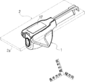
- FIGS. 1 and 2 show a state in which the back monitor unit 1 is attached to the glass inner surface 2a of the rear window glass 2 on the vehicle interior side.
- the back monitor unit 1 is attached to the glass inner surface 2a of the rear window glass 2 and images the rear side of the vehicle to generate and output image data.
- the image data output from the back monitor unit 1 is output on any display visible from the driver's seat.
- the back monitor unit 1 is a specific example of an in-vehicle device.
- the rear window glass 2 is a specific example of an object to be attached.
- the height direction, the longitudinal direction, and the width direction are directions orthogonal to each other.
- the height direction is a specific example of the first direction, and is a direction orthogonal to the glass inner surface 2a of the rear window glass 2.
- the height direction includes an upper direction and a lower direction.
- the upward direction is the direction of the back monitor unit 1 as viewed from the rear window glass 2.
- the downward direction is the opposite direction of the upward direction.
- the glass inner surface 2a of the rear window glass 2 is slightly curved, the height direction is defined based on the portion of the glass inner surface 2a of the rear window glass 2 to which the back monitor unit 1 is attached. ..
- the longitudinal direction is one specific example of the second direction, and is the same as the optical axis of the back monitor unit 1 in a plan view when the back monitor unit 1 is viewed in a direction orthogonal to the glass inner surface 2a of the rear window glass 2. It is a parallel direction.
- the longitudinal direction includes the front and the rear.
- the front side is a direction that is the imaging direction of the back monitor unit 1 when the back monitor unit 1 is viewed in a direction orthogonal to the glass inner surface 2a of the rear window glass 2.
- the back is the opposite direction of the front.
- the width direction is a specific example of the third direction, and is a direction orthogonal to the height direction and the longitudinal direction.
- the height direction, the width direction, and the longitudinal direction are used for convenience of description, and do not limit the posture of the back monitor unit 1 in the use state.
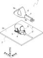
- the back monitor unit 1 includes a camera unit 3 and a base 4.
- the back monitor unit 1 may include an optical axis adjusting mechanism 5, a main body cover 6, and a cable cover 7.
- the camera unit 3 includes a unit body 8 and an output cable 9.
- the unit body 8 is a specific example of a vehicle-mounted device body.
- the unit main body 8 includes an imaging unit 10 such as a CCD (Charged-coupled devices) camera or a CMOS (Complementary metal-oxide-semiconductor) camera, and a housing 11 that houses the imaging unit 10 therein. ,,.
- CCD Charge-coupled devices
- CMOS Complementary metal-oxide-semiconductor
- the image pickup unit 10 has an optical axis 10a indicated by a chain line in FIG.
- the housing 11 extends along the optical axis direction and is formed so as to taper toward the rear.
- the housing 11 has two side surfaces 11 a facing the width direction and a bottom surface 11 b facing the base 4 and the rear window glass 2.
- the bottom surface 11b is a specific example of the facing surface.
- the housing 11 further includes a swing shaft portion 11c protruding from each side surface 11a in the width direction at the rear end, and a female screw portion 11d formed rearward of the swing shaft portion 11c.
- the output cable 9 is a specific example of a cable, and is a cable for outputting the image data captured and generated by the image capturing unit 10 to the outside. As shown in FIG. 5, the output cable 9 is pulled out from the bottom surface 11 b of the housing 11 of the unit body 8 toward the base 4 so as to approach the base 4. The output cable 9 is drawn out from the bottom surface 11b of the housing 11 of the unit body 8 so as to come into contact with the base 4 and bend. The output cable 9 is pulled out from the bottom surface 11b of the housing 11 of the unit body 8 toward the glass inner surface 2a of the rear window glass 2. The output cable 9 is pulled out from the bottom surface 11b of the housing 11 of the unit body 8 in a direction substantially orthogonal to the optical axis 10a of the imaging unit 10.
- the imaging unit 10 is a specific example of electronic components.
- the base 4 mounts the unit main body 8 and is adhered to the glass inner surface 2a of the rear window glass 2 via the double-sided tape 17, and has a plate-shaped base main body 15 And a cable guide 16.
- the base body 15 is a plate parallel to the glass inner surface 2a of the rear window glass 2. As shown in FIG. 5, the base body 15 is bonded to the glass inner surface 2 a of the rear window glass 2 via the double-sided tape 17. As shown in FIGS. 5 and 6, the base body 15 has an adhesive surface 15a that faces the inner glass surface 2a of the rear window glass 2 and is adhered to the inner glass surface 2a of the rear window glass 2 via the double-sided tape 17. And a component mounting surface 15b on the opposite side of the adhesive surface 15a on which the camera unit 3 and the optical axis adjusting mechanism 5 are mounted.
- the adhesive surface 15a is a specific example of the first surface.
- the component mounting surface 15b is a specific example of the second surface.
- the shape of the base body 15 is not limited to a plate shape, and may have a thickness or irregularities.
- the cable guide 16 is a guide for guiding the output cable 9 pulled out from the unit body 8 of the camera unit 3.
- the cable guide 16 has a guide pillar 16a protruding upward from the base body 15 and a guide protrusion 16b protruding in the width direction from the upper end of the guide pillar 16a.
- the guide protrusion 16b is supported in a cantilever shape by the guide pillar 16a, and has a height-direction opposing relationship with the component mounting surface 15b of the base body 15.
- the cable guide 16 is not an essential component, and the base 4 may be composed of only the plate-shaped base body 15.
- the optical axis adjusting mechanism 5 adjusts the tilt angle of the optical axis 10 a of the image pickup unit 10. That is, the angle of inclination of the rear window glass 2 with respect to the horizontal differs depending on the vehicle type, and is generally within the range of 10 degrees to 85 degrees. Therefore, in order to set the orientation of the optical axis 10a of the imaging unit 10 to an appropriate orientation, a mechanism for adjusting the orientation of the optical axis 10a of the imaging unit 10 after the back monitor unit 1 is attached to the rear window glass 2 is required. .. In the present embodiment, by using the optical axis adjusting mechanism 5, the direction of the optical axis 10a of the image pickup unit 10 can be adjusted.
- the optical axis adjusting mechanism 5 has an adjusting plate 20 fixed to the component mounting surface 15b of the base 4.
- the adjusting plate 20 is formed with a shaft portion housing portion 20a for housing the swing shaft portion 11c of the housing 11 of the unit body 8 and a long hole 20b extending in an arc around the shaft portion housing portion 20a. ing. With this configuration, by housing the swing shaft portion 11c of the housing 11 of the unit body 8 in the shaft portion housing portion 20a of the adjustment plate 20 of the optical axis adjusting mechanism 5, the unit body 8 moves around the swing shaft portion 11c. It is supported by the base 4 so as to be swingable.
- the male screw 21 is screwed into the female screw portion 11d of the housing 11 through the elongated hole 20b in the adjusted state.
- the position of the housing 11 with respect to the adjustment plate 20 is fixed, and thus the orientation of the optical axis 10a of the imaging unit 10 is fixed with respect to the rear window glass 2.
- the main body cover 6 is a cover that covers the unit main body 8 of the camera unit 3.
- the body cover 6 is formed in a U-shaped cross section that opens downward.
- the main body cover 6 is formed with an imaging opening 6a that opens forward so as not to block the imaging by the imaging unit 10.
- the body cover 6 is formed with a cable opening 6b through which the output cable 9 passes when the output cable 9 pulled out from the unit body 8 is wired rearward.
- the cable opening 6b is formed as a U-shaped recess that opens rearward and opens downward.
- the cable cover 7 is a cover that covers the output cable 9 that extends from the unit body 8 and extends rearward.
- the output cable 9 extends in the longitudinal direction and has a U-shaped cross section.
- the output cable 9 is pulled out from the bottom surface 11b of the unit body 8 so as to approach the base 4. Therefore, as compared with the case where the output cable 9 is pulled out rearward from the unit body 8, a large space 25 on the rear side of the unit body 8 can be secured. That is, it is possible to suppress the amount of the back monitor unit 1 protruding toward the vehicle compartment. Therefore, miniaturization of the back monitor unit 1 is achieved, and even if the back monitor unit 1 is attached, the vehicle interior environment of the vehicle can be maintained without any problem.
- the output cable 9 pulled out from the bottom surface 11b of the unit body 8 is curved rearward by coming into contact with the component mounting surface 15b of the base 4.
- the output cable 9 extends parallel to the glass inner surface 2a of the rear window glass 2.
- the elastic restoring force of the output cable 9 is 4 acts to peel off the glass inner surface 2a of the rear window glass 2.
- the output cable 9 pulled out from the bottom surface 11b of the unit body 8 is curved at the component mounting surface 15b of the base 4.
- the elastic restoring force of the output cable 9 acts on the component mounting surface 15b of the base 4 that comes into contact with the bending point of the output cable 9, but acts to peel the base 4 from the glass inner surface 2a of the rear window glass 2.
- the back monitor unit 1 is less likely to fall off the rear window glass 2.
- the output cable 9 is wired so as to pass between the guide protrusion 16b of the cable guide 16 and the base body 15. Therefore, even when the angle ⁇ between the optical axis 10a of the imaging unit 10 and the glass inner surface 2a of the rear window glass 2 is set to, for example, 80 degrees, the output cable 9 is prohibited from being lifted from the base 4, and the output cable 9 is not connected to the base 4. It is possible to maintain the above-described configuration in which the output cable 9 bends due to the contact with the component mounting surface 15b.
- the back monitor unit 1 as an in-vehicle device is equipped with a unit body 8 as an in-vehicle device body that accommodates an imaging unit 10 as an electronic component inside, and the unit body 8.
- a base 4 bonded to a rear window glass 2 as an attachment target and an output cable 9 as a cable pulled out from the unit body 8 are also provided.
- the output cable 9 contacts the base 4 and is drawn out so as to be curved.
- the unit main body 8 has a bottom surface 11b as a facing surface facing the base 4.
- the output cable 9 is pulled out from the bottom surface 11b.
- the in-vehicle device is not limited to the back monitor unit 1, but may be one that monitors the front or side of the vehicle.
- the base 4 has an adhesive surface 15a as a first surface to be adhered to the rear window glass 2 and a component mounting surface 15b as a second surface opposite to the adhesive surface 15a.
- the output cable 9 abuts on the component mounting surface 15b of the base 4 and is drawn out so as to be curved.
- an optical axis adjusting mechanism 5 is further provided as an adjusting mechanism for adjusting the attitude of the unit main body 8 with respect to the base 4. According to the above configuration, the direction of the optical axis 10a of the imaging unit 10 can be adjusted appropriately regardless of the inclination angle of the rear window glass 2 with respect to the horizontal.
- the base 4 is extended to a position where the output cable 9 comes into contact with the base 4 within a range adjusted by the optical axis adjusting mechanism 5.
- the output cable 9 is pulled out from the unit main body 8 in a direction substantially orthogonal to the optical axis 10a of the imaging unit 10. According to the above configuration, downsizing of the back monitor unit 1 can be realized at a higher level.
- the base 4 has a cable guide 16 that guides the output cable 9.
- the output cable 9 runs between the cable guide 16 and the base 4. According to the above configuration, the output cable 9 can be brought into contact with the base 4 and curved regardless of the posture of the unit main body 8 with respect to the base 4.
- the present invention is not limited to the above embodiment.
- the above-described embodiment has been described as an example of the back monitor unit 1, but it is also applicable to, for example, a camera unit for a drive recorder mounted on the windshield.
- the present invention is applicable to in-vehicle devices and has industrial applicability.
Landscapes
- Physics & Mathematics (AREA)
- General Physics & Mathematics (AREA)
- Engineering & Computer Science (AREA)
- Mechanical Engineering (AREA)
- Multimedia (AREA)
- Signal Processing (AREA)
- Fittings On The Vehicle Exterior For Carrying Loads, And Devices For Holding Or Mounting Articles (AREA)
- Accessories Of Cameras (AREA)
- Studio Devices (AREA)
Abstract
バックモニターユニット(1)は、内部に撮像部(10)を収容するユニット本体(8)と、ユニット本体(8)を搭載すると共にリアウィンドウガラス(2)に接着されるベース(4)と、ユニット本体(8)から引き出された出力ケーブル(9)と、を備える。出力ケーブル(9)は、ベース(4)に当接して湾曲するように引き出されている。
Description
本発明は、車載機器に関する。
特許文献1(特開2018-73879号公報)は、フロントガラスに取り付けられるドライブレコーダを開示している。
ところで、車載機器の分野においては、車載機器の小型化に加え、車両に対する装着の強度も求められている。
本開示の目的は、車載機器を小型化しつつ、車両に対して車載機器を強固に装着する技術を提供することにある。
本実施形態の第1の観点によれば、内部に電子部品を収容する車載機器本体と、前記車載機器本体を搭載すると共に、取付対象物に接着されるベースと、前記車載機器本体から引き出されたケーブルと、を備え、前記ケーブルは、前記ベースに当接して湾曲するように引き出されている、車載機器が提供される。
本実施形態によれば、車載機器を小型化しつつ、車両に対して車載機器を強固に装着することができる。
以下、図面を参照して、本開示の一実施形態に係るバックモニターユニット1を説明する。図1及び図2には、リアウィンドウガラス2の車室側となるガラス内面2aにバックモニターユニット1を取り付けた様子を示している。図1及び図2に示すように、バックモニターユニット1は、リアウィンドウガラス2のガラス内面2aに取り付けられ、車両の後方を撮像して画像データを生成し、出力するものである。バックモニターユニット1から出力された画像データは、運転席から視認可能な任意のディスプレイ上に出力される。バックモニターユニット1は、車載機器の一具体例である。リアウィンドウガラス2は、取付対象物の一具体例である。
以下、説明の便宜上、図3以降の図面においては、バックモニターユニット1を上下逆にして描いている。
図3において、「高さ方向」「長手方向」「幅方向」を定義する。高さ方向、長手方向、幅方向は互いに直交する方向である。高さ方向は、第1の方向の一具体例であって、リアウィンドウガラス2のガラス内面2aに対して直交する方向である。高さ方向は、上方向と下方向を含む。上方向は、リアウィンドウガラス2から見たバックモニターユニット1の方向である。下方向は、上方向の反対方向である。なお、リアウィンドウガラス2のガラス内面2aは僅かに湾曲しているが、上記の高さ方向は、リアウィンドウガラス2のガラス内面2aのうちバックモニターユニット1が取り付けられる部分に基づいて定義される。長手方向は、第2の方向の一具体例であって、リアウィンドウガラス2のガラス内面2aに対して直交する方向でバックモニターユニット1を見た平面視において、バックモニターユニット1の光軸と平行となる方向である。長手方向は、前方と後方を含む。前方は、リアウィンドウガラス2のガラス内面2aに対して直交する方向でバックモニターユニット1を見たときにバックモニターユニット1の撮像方向となる方向である。後方は、前方の反対方向である。幅方向は、第3の方向の一具体例であって、高さ方向及び長手方向に対して直交する方向である。なお、高さ方向、幅方向、長手方向は、説明の便宜上使用するものであって、バックモニターユニット1の使用状態における姿勢を限定するものではない。
図3及び図4に示すように、バックモニターユニット1は、カメラユニット3と、ベース4と、を備えている。バックモニターユニット1は、光軸調整機構5と、本体カバー6と、ケーブルカバー7と、を備えてもよい。
(カメラユニット3)
図4に示すように、カメラユニット3は、ユニット本体8と、出力ケーブル9と、で構成されている。ユニット本体8は、車載機器本体の一具体例である。図5に示すように、ユニット本体8は、例えばCCD(Charged-coupled devices)カメラやCMOS(Complementary metal-oxide-semiconductor)カメラなどの撮像部10と、撮像部10を内部に収容するハウジング11と、で構成されている。
図4に示すように、カメラユニット3は、ユニット本体8と、出力ケーブル9と、で構成されている。ユニット本体8は、車載機器本体の一具体例である。図5に示すように、ユニット本体8は、例えばCCD(Charged-coupled devices)カメラやCMOS(Complementary metal-oxide-semiconductor)カメラなどの撮像部10と、撮像部10を内部に収容するハウジング11と、で構成されている。
撮像部10は、図5において一点鎖線で示す光軸10aを有する。ハウジング11は、光軸方向に沿って延びており、後方に向かうにつれて先細るように形成されている。ハウジング11は、幅方向を向く2つの側面11aと、ベース4及びリアウィンドウガラス2を向く底面11bと、を有する。底面11bは、対向面の一具体例である。ハウジング11は、更に、後方端において各側面11aから幅方向に突出する揺動軸部11cと、揺動軸部11cよりも後方に形成された雌ねじ部11dと、を有する。
出力ケーブル9は、ケーブルの一具体例であって、撮像部10で撮像されて生成された画像データを外部に出力するためのケーブルである。図5に示すように、出力ケーブル9は、ユニット本体8のハウジング11の底面11bから、ベース4に近づくようにベース4に向かって引き出されている。出力ケーブル9は、ユニット本体8のハウジング11の底面11bから、ベース4に当接して湾曲するように引き出されている。出力ケーブル9は、ユニット本体8のハウジング11の底面11bから、リアウィンドウガラス2のガラス内面2aに向かって引き出されている。出力ケーブル9は、ユニット本体8のハウジング11の底面11bから、撮像部10の光軸10aに対して実質的に直交する方向で引き出されている。撮像部10は、電子部品の一具体例である。
(ベース4)
図5に示すように、ベース4は、ユニット本体8を搭載するものであって、リアウィンドウガラス2のガラス内面2aに両面テープ17を介して接着されるものであり、板状のベース本体15と、ケーブルガイド16と、により構成されている。
図5に示すように、ベース4は、ユニット本体8を搭載するものであって、リアウィンドウガラス2のガラス内面2aに両面テープ17を介して接着されるものであり、板状のベース本体15と、ケーブルガイド16と、により構成されている。
ベース本体15は、リアウィンドウガラス2のガラス内面2aに対して平行な板体である。図5に示すように、ベース本体15は、両面テープ17を介してリアウィンドウガラス2のガラス内面2aに接着される。図5及び図6に示すように、ベース本体15は、リアウィンドウガラス2のガラス内面2aに対向すると共にリアウィンドウガラス2のガラス内面2aに両面テープ17を介して接着される接着面15aと、接着面15aの反対側の面であってカメラユニット3や光軸調整機構5が搭載される部品搭載面15bと、を有する。接着面15aは、第1の面の一具体例である。部品搭載面15bは、第2の面の一具体例である。ベース本体15の形状は、板状に限定されず、厚みを有してもよく、凹凸を有してもよい。
ケーブルガイド16は、カメラユニット3のユニット本体8から引き出された出力ケーブル9を案内するガイドである。図6に示すように、ケーブルガイド16は、ベース本体15から上方に突出するガイドピラー16aと、ガイドピラー16aの上端から幅方向に突出するガイド突起16bと、を有する。ガイド突起16bは、ガイドピラー16aによって片持梁状に支持されており、ベース本体15の部品搭載面15bと高さ方向で対向関係にある。ケーブルガイド16は必須の構成ではなく、ベース4は、板状のベース本体15のみで構成されてもよい。
(光軸調整機構5)
図5に戻り、光軸調整機構5は、撮像部10の光軸10aの傾斜角を調整するものである。即ち、リアウィンドウガラス2の水平に対する傾斜角は、車種に応じて異なっており、概ね10度から85度の範囲内とされている。従って、撮像部10の光軸10aの向きを適切な向きとするには、バックモニターユニット1をリアウィンドウガラス2に取り付けた後に撮像部10の光軸10aの向きを調整する機構が必要となる。本実施形態では、光軸調整機構5を用いることで、撮像部10の光軸10aの向きを調整することができる。
図5に戻り、光軸調整機構5は、撮像部10の光軸10aの傾斜角を調整するものである。即ち、リアウィンドウガラス2の水平に対する傾斜角は、車種に応じて異なっており、概ね10度から85度の範囲内とされている。従って、撮像部10の光軸10aの向きを適切な向きとするには、バックモニターユニット1をリアウィンドウガラス2に取り付けた後に撮像部10の光軸10aの向きを調整する機構が必要となる。本実施形態では、光軸調整機構5を用いることで、撮像部10の光軸10aの向きを調整することができる。
光軸調整機構5は、ベース4の部品搭載面15bに固定された調整板20を有する。調整板20には、ユニット本体8のハウジング11の揺動軸部11cを収容する軸部収容部20aと、軸部収容部20aを中心として円弧を描くように延びる長孔20bと、が形成されている。この構成で、ユニット本体8のハウジング11の揺動軸部11cを光軸調整機構5の調整板20の軸部収容部20aに収容することで、ユニット本体8は、揺動軸部11cまわりで揺動自在となるようにベース4に支持されることになる。また、撮像部10の光軸10aの向きを好適に調整した後、その調整後の状態で雄ねじ21を長孔20bを介してハウジング11の雌ねじ部11dに螺合させる。これにより、ハウジング11の調整板20に対する位置が固定され、もって、撮像部10の光軸10aの向きがリアウィンドウガラス2に対して固定されることになる。
(本体カバー6)
図4に示すように、本体カバー6は、カメラユニット3のユニット本体8を覆うカバーである。本体カバー6は、下方に向かって開口する断面U字状に形成されている。本体カバー6には、撮像部10による撮像を遮らないように、前方に開口する撮像開口6aが形成されている。また、本体カバー6には、ユニット本体8から引き出された出力ケーブル9を後方に向かって配線する際に出力ケーブル9が通過するケーブル開口6bが形成されている。ケーブル開口6bは、後方に向かって開口すると共に、下方に向かって開口するU字状の窪みとして形成されている。
図4に示すように、本体カバー6は、カメラユニット3のユニット本体8を覆うカバーである。本体カバー6は、下方に向かって開口する断面U字状に形成されている。本体カバー6には、撮像部10による撮像を遮らないように、前方に開口する撮像開口6aが形成されている。また、本体カバー6には、ユニット本体8から引き出された出力ケーブル9を後方に向かって配線する際に出力ケーブル9が通過するケーブル開口6bが形成されている。ケーブル開口6bは、後方に向かって開口すると共に、下方に向かって開口するU字状の窪みとして形成されている。
(ケーブルカバー7)
ケーブルカバー7は、ユニット本体8から引き出され、後方に向かって延びる出力ケーブル9を覆うカバーである。出力ケーブル9は、長手方向に沿って延びており、断面U字状に形成されている。
ケーブルカバー7は、ユニット本体8から引き出され、後方に向かって延びる出力ケーブル9を覆うカバーである。出力ケーブル9は、長手方向に沿って延びており、断面U字状に形成されている。
ここで、出力ケーブル9の引き出し方向について補足説明する。図5に示すように、本実施形態では、出力ケーブル9は、ベース4に近づくようにユニット本体8の底面11bから引き出されている。従って、出力ケーブル9がユニット本体8から後方に向かって引き出される場合と比較して、ユニット本体8の後方側のスペース25を大きく確保することができる。即ち、バックモニターユニット1が車室側に突き出る量を抑えることができる。従って、バックモニターユニット1の小型化が達成されると共に、バックモニターユニット1を取り付けても車両の車室環境を問題なく維持することができる。
また、図6に示すように、ユニット本体8の底面11bから引き出された出力ケーブル9は、ベース4の部品搭載面15bに当接することで後方に向かって湾曲している。この結果、出力ケーブル9は、リアウィンドウガラス2のガラス内面2aに対して平行に延びている。仮に、ユニット本体8の底面11bから引き出された出力ケーブル9がリアウィンドウガラス2のガラス内面2aに当接することで後方に向かって湾曲しているとすると、出力ケーブル9の弾性復元力は、ベース4をリアウィンドウガラス2のガラス内面2aから引き剥がすように作用することになる。これに対し、本実施形態では、ユニット本体8の底面11bから引き出された出力ケーブル9をベース4の部品搭載面15bで湾曲させている。従って、出力ケーブル9の弾性復元力は、出力ケーブル9の湾曲点と接触するベース4の部品搭載面15bに作用するものの、ベース4をリアウィンドウガラス2のガラス内面2aから引き剥がすように作用することがない。このため、バックモニターユニット1がリアウィンドウガラス2から脱落し難くなる。
また、図5に示すように、出力ケーブル9は、ケーブルガイド16のガイド突起16bとベース本体15の間を通るように配線されている。従って、撮像部10の光軸10aとリアウィンドウガラス2のガラス内面2aとの角度θを例えば80度とした場合でも、出力ケーブル9のベース4からの浮きが禁止され、出力ケーブル9がベース4の部品搭載面15bに当接し、この当接により出力ケーブル9が湾曲する上述した構成を維持することができる。
以上に、本開示の好適な実施形態を説明したが、上記実施形態は以下の特長を有する。
即ち、図4及び図5に示すように、車載機器としてのバックモニターユニット1は、内部に電子部品としての撮像部10を収容する車載機器本体としてのユニット本体8と、ユニット本体8を搭載すると共に取付対象物としてのリアウィンドウガラス2に接着されるベース4と、ユニット本体8から引き出されたケーブルとしての出力ケーブル9と、を備える。出力ケーブル9は、ベース4に当接して湾曲するように引き出されている。以上の構成によれば、バックモニターユニット1を小型化しつつ、車両に対してバックモニターユニット1を強固に装着することができる。
また、図4及び図5に示すように、ユニット本体8は、ベース4に対向する対向面としての底面11bを有する。出力ケーブル9は、底面11bから引き出されている。
なお、車載機器としては、バックモニターユニット1に限らず、車両の前方や側方をモニタリングするものであってもよい。
また、図5に示すように、ベース4は、リアウィンドウガラス2に接着される第1の面としての接着面15aと、接着面15aと反対側の第2の面としての部品搭載面15bと、を有する。出力ケーブル9は、ベース4の部品搭載面15bに当接して湾曲するように引き出されている。
また、図5に示すように、ユニット本体8のベース4に対する姿勢を調整する調整機構としての光軸調整機構5を更に備える。以上の構成によれば、リアウィンドウガラス2の水平に対する傾斜角の如何にかかわらず、撮像部10の光軸10aの向きを好適に調整することができる。
また、図5に示すように、ベース4は、光軸調整機構5で調整される範囲で出力ケーブル9がベース4に当接する位置まで延伸されている。
また、図5に示すように、出力ケーブル9は、撮像部10の光軸10aに対して実質的に直交する方向で、ユニット本体8から引き出されている。以上の構成によれば、バックモニターユニット1の小型化が一層高いレベルで実現される。
また、図5に示すように、ベース4は、出力ケーブル9を案内するケーブルガイド16を有する。出力ケーブル9は、ケーブルガイド16とベース4の間を通っている。以上の構成によれば、ベース4に対するユニット本体8の姿勢の如何にかかわらず、出力ケーブル9をベース4に当接させて湾曲させることが可能となる。
本発明は、上述した実施形態に限定されるものではない。上述した実施形態は、バックモニターユニット1の例として説明したが、ウィンドシールドに装着される、例えばドライブレコーダ用のカメラユニットなどにも適用可能である。
この出願は、2018年12月26日に出願された日本出願特願2018-242531を基礎とする優先権を主張し、その開示の全てをここに取り込む。
本発明は、車載機器に適用可能であり、産業上の利用可能性を有する。
1 バックモニターユニット
2 リアウィンドウガラス
2a ガラス内面
3 カメラユニット
4 ベース
5 光軸調整機構
6 本体カバー
6a 撮像開口
6b ケーブル開口
7 ケーブルカバー
8 ユニット本体
9 出力ケーブル
10 撮像部
10a 光軸
11 ハウジング
11a 側面
11b 底面
11c 揺動軸部
11d 雌ねじ部
15 ベース本体
15a 接着面
15b 部品搭載面
16 ケーブルガイド
16a ガイドピラー
16b ガイド突起
17 両面テープ
20 調整板
20a 軸部収容部
20b 長孔
21 雄ねじ
25 スペース
2 リアウィンドウガラス
2a ガラス内面
3 カメラユニット
4 ベース
5 光軸調整機構
6 本体カバー
6a 撮像開口
6b ケーブル開口
7 ケーブルカバー
8 ユニット本体
9 出力ケーブル
10 撮像部
10a 光軸
11 ハウジング
11a 側面
11b 底面
11c 揺動軸部
11d 雌ねじ部
15 ベース本体
15a 接着面
15b 部品搭載面
16 ケーブルガイド
16a ガイドピラー
16b ガイド突起
17 両面テープ
20 調整板
20a 軸部収容部
20b 長孔
21 雄ねじ
25 スペース
Claims (7)
- 内部に電子部品を収容する車載機器本体と、
前記車載機器本体を搭載すると共に、取付対象物に接着されるベースと、
前記車載機器本体から引き出されたケーブルと、
を備え、
前記ケーブルは、前記ベースに当接して湾曲するように引き出されている、
車載機器。 - 前記車載機器本体は、前記ベースに対向する対向面を有し、
前記ケーブルは、前記対向面から引き出されている、
請求項1に記載の車載機器。 - 前記ベースは、前記取付対象物に接着される第1の面と、前記第1の面と反対側の第2の面と、を有し、
前記ケーブルは、前記ベースの前記第2の面に当接して湾曲するように引き出されている、
請求項1又は2に記載の車載機器。 - 前記車載機器本体の前記ベースに対する姿勢を調整する調整機構を更に備える、
請求項1から3までの何れか1項に記載の車載機器。 - 前記ベースは、前記調整機構で調整される範囲で前記ケーブルが前記ベースに当接する位置まで延伸されている、
請求項4に記載の車載機器。 - 前記電子部品はカメラであり、
前記ケーブルは、前記カメラの光軸に対して直交する方向で、前記車載機器本体から引き出されている、
請求項1から5までの何れか1項に記載の車載機器。 - 前記ベースは、前記ケーブルを案内するケーブルガイドを有し、
前記ケーブルは、前記ケーブルガイドと前記ベースの間を通っている、
請求項1から6までの何れか1項に記載の車載機器。
Applications Claiming Priority (2)
| Application Number | Priority Date | Filing Date | Title |
|---|---|---|---|
| JP2018-242531 | 2018-12-26 | ||
| JP2018242531A JP2020104565A (ja) | 2018-12-26 | 2018-12-26 | 車載機器 |
Publications (1)
| Publication Number | Publication Date |
|---|---|
| WO2020137022A1 true WO2020137022A1 (ja) | 2020-07-02 |
Family
ID=71126066
Family Applications (1)
| Application Number | Title | Priority Date | Filing Date |
|---|---|---|---|
| PCT/JP2019/035691 Ceased WO2020137022A1 (ja) | 2018-12-26 | 2019-09-11 | 車載機器 |
Country Status (2)
| Country | Link |
|---|---|
| JP (1) | JP2020104565A (ja) |
| WO (1) | WO2020137022A1 (ja) |
Cited By (1)
| Publication number | Priority date | Publication date | Assignee | Title |
|---|---|---|---|---|
| WO2025187321A1 (ja) * | 2024-03-07 | 2025-09-12 | 株式会社クボタ | カメラ、カメラの固定構造、作業機 |
Families Citing this family (1)
| Publication number | Priority date | Publication date | Assignee | Title |
|---|---|---|---|---|
| WO2023234240A1 (ja) * | 2022-05-30 | 2023-12-07 | Agc株式会社 | 車両用ガラス及びカメラユニット |
Citations (4)
| Publication number | Priority date | Publication date | Assignee | Title |
|---|---|---|---|---|
| JP2012226030A (ja) * | 2011-04-18 | 2012-11-15 | Beat Sonic:Kk | カメラ装置 |
| JP2017073751A (ja) * | 2015-10-09 | 2017-04-13 | パナソニックIpマネジメント株式会社 | 車載カメラ及び車両 |
| JP2017124732A (ja) * | 2016-01-14 | 2017-07-20 | 株式会社ティーズコンシェル | 自動車用バックカメラの取付構造 |
| WO2018155302A1 (ja) * | 2017-02-21 | 2018-08-30 | 住友建機株式会社 | ショベル |
-
2018
- 2018-12-26 JP JP2018242531A patent/JP2020104565A/ja active Pending
-
2019
- 2019-09-11 WO PCT/JP2019/035691 patent/WO2020137022A1/ja not_active Ceased
Patent Citations (4)
| Publication number | Priority date | Publication date | Assignee | Title |
|---|---|---|---|---|
| JP2012226030A (ja) * | 2011-04-18 | 2012-11-15 | Beat Sonic:Kk | カメラ装置 |
| JP2017073751A (ja) * | 2015-10-09 | 2017-04-13 | パナソニックIpマネジメント株式会社 | 車載カメラ及び車両 |
| JP2017124732A (ja) * | 2016-01-14 | 2017-07-20 | 株式会社ティーズコンシェル | 自動車用バックカメラの取付構造 |
| WO2018155302A1 (ja) * | 2017-02-21 | 2018-08-30 | 住友建機株式会社 | ショベル |
Cited By (1)
| Publication number | Priority date | Publication date | Assignee | Title |
|---|---|---|---|---|
| WO2025187321A1 (ja) * | 2024-03-07 | 2025-09-12 | 株式会社クボタ | カメラ、カメラの固定構造、作業機 |
Also Published As
| Publication number | Publication date |
|---|---|
| JP2020104565A (ja) | 2020-07-09 |
Similar Documents
| Publication | Publication Date | Title |
|---|---|---|
| JP6997712B2 (ja) | 電子機器、カメラ装置、並びにシールド・シャーシー | |
| CN110446629B (zh) | 车载摄像装置 | |
| US7604421B2 (en) | Imaging device module | |
| JP2016057468A (ja) | 屈曲撮像装置 | |
| CN108808295B (zh) | 车载摄像机 | |
| WO2020137022A1 (ja) | 車載機器 | |
| JP6767186B2 (ja) | 車載用カメラ装置 | |
| JP2013190772A (ja) | 撮像装置 | |
| US10609261B2 (en) | Optical camera to be mounted on vehicles | |
| JP6923491B2 (ja) | ドライブレコーダ | |
| KR101577672B1 (ko) | 흔들림 보정 기능을 갖는 카메라모듈 | |
| JP2020114728A (ja) | 車載撮像装置 | |
| US20150319871A1 (en) | Holding apparatus that holds electronic apparatus | |
| JP5157877B2 (ja) | 撮像素子の取付構造及び撮像装置 | |
| CN108702436B (zh) | 电子部件安装构件、摄像装置以及车载用摄像装置 | |
| JP6004726B2 (ja) | 撮像装置 | |
| CN117518395A (zh) | 棱镜驱动装置 | |
| US20240045309A1 (en) | Optical element drive device, camera module, and camera mounting device | |
| WO2017154745A1 (ja) | 撮像装置 | |
| JP5187181B2 (ja) | 撮像装置 | |
| KR20110028840A (ko) | 카메라가 장착된 차량용 룸미러 조립체 | |
| JP2012210871A (ja) | 電子機器保持具および電子機器取り付けユニット | |
| JP7143636B2 (ja) | 撮像装置 | |
| JP6971713B2 (ja) | 撮像装置 | |
| JP2018169446A (ja) | 電子機器 |
Legal Events
| Date | Code | Title | Description |
|---|---|---|---|
| 121 | Ep: the epo has been informed by wipo that ep was designated in this application |
Ref document number: 19903213 Country of ref document: EP Kind code of ref document: A1 |
|
| NENP | Non-entry into the national phase |
Ref country code: DE |
|
| 122 | Ep: pct application non-entry in european phase |
Ref document number: 19903213 Country of ref document: EP Kind code of ref document: A1 |