WO2020136749A1 - 変倍光学系、光学機器および変倍光学系の製造方法 - Google Patents
変倍光学系、光学機器および変倍光学系の製造方法 Download PDFInfo
- Publication number
- WO2020136749A1 WO2020136749A1 PCT/JP2018/047781 JP2018047781W WO2020136749A1 WO 2020136749 A1 WO2020136749 A1 WO 2020136749A1 JP 2018047781 W JP2018047781 W JP 2018047781W WO 2020136749 A1 WO2020136749 A1 WO 2020136749A1
- Authority
- WO
- WIPO (PCT)
- Prior art keywords
- lens group
- focusing
- focusing lens
- lens
- optical system
- Prior art date
- Legal status (The legal status is an assumption and is not a legal conclusion. Google has not performed a legal analysis and makes no representation as to the accuracy of the status listed.)
- Ceased
Links
Images





Classifications
-
- G—PHYSICS
- G02—OPTICS
- G02B—OPTICAL ELEMENTS, SYSTEMS OR APPARATUS
- G02B15/00—Optical objectives with means for varying the magnification
- G02B15/14—Optical objectives with means for varying the magnification by axial movement of one or more lenses or groups of lenses relative to the image plane for continuously varying the equivalent focal length of the objective
- G02B15/146—Optical objectives with means for varying the magnification by axial movement of one or more lenses or groups of lenses relative to the image plane for continuously varying the equivalent focal length of the objective having more than five groups
- G02B15/1461—Optical objectives with means for varying the magnification by axial movement of one or more lenses or groups of lenses relative to the image plane for continuously varying the equivalent focal length of the objective having more than five groups the first group being positive
-
- G—PHYSICS
- G02—OPTICS
- G02B—OPTICAL ELEMENTS, SYSTEMS OR APPARATUS
- G02B3/00—Simple or compound lenses
- G02B3/02—Simple or compound lenses with non-spherical faces
- G02B3/04—Simple or compound lenses with non-spherical faces with continuous faces that are rotationally symmetrical but deviate from a true sphere, e.g. so called "aspheric" lenses
-
- G—PHYSICS
- G02—OPTICS
- G02B—OPTICAL ELEMENTS, SYSTEMS OR APPARATUS
- G02B7/00—Mountings, adjusting means, or light-tight connections, for optical elements
- G02B7/02—Mountings, adjusting means, or light-tight connections, for optical elements for lenses
- G02B7/021—Mountings, adjusting means, or light-tight connections, for optical elements for lenses for more than one lens
-
- G—PHYSICS
- G02—OPTICS
- G02B—OPTICAL ELEMENTS, SYSTEMS OR APPARATUS
- G02B7/00—Mountings, adjusting means, or light-tight connections, for optical elements
- G02B7/02—Mountings, adjusting means, or light-tight connections, for optical elements for lenses
- G02B7/04—Mountings, adjusting means, or light-tight connections, for optical elements for lenses with mechanism for focusing or varying magnification
- G02B7/09—Mountings, adjusting means, or light-tight connections, for optical elements for lenses with mechanism for focusing or varying magnification adapted for automatic focusing or varying magnification
-
- G—PHYSICS
- G02—OPTICS
- G02B—OPTICAL ELEMENTS, SYSTEMS OR APPARATUS
- G02B13/00—Optical objectives specially designed for the purposes specified below
- G02B13/18—Optical objectives specially designed for the purposes specified below with lenses having one or more non-spherical faces, e.g. for reducing geometrical aberration
-
- G—PHYSICS
- G02—OPTICS
- G02B—OPTICAL ELEMENTS, SYSTEMS OR APPARATUS
- G02B15/00—Optical objectives with means for varying the magnification
- G02B15/14—Optical objectives with means for varying the magnification by axial movement of one or more lenses or groups of lenses relative to the image plane for continuously varying the equivalent focal length of the objective
- G02B15/16—Optical objectives with means for varying the magnification by axial movement of one or more lenses or groups of lenses relative to the image plane for continuously varying the equivalent focal length of the objective with interdependent non-linearly related movements between one lens or lens group, and another lens or lens group
- G02B15/20—Optical objectives with means for varying the magnification by axial movement of one or more lenses or groups of lenses relative to the image plane for continuously varying the equivalent focal length of the objective with interdependent non-linearly related movements between one lens or lens group, and another lens or lens group having an additional movable lens or lens group for varying the objective focal length
-
- G—PHYSICS
- G02—OPTICS
- G02B—OPTICAL ELEMENTS, SYSTEMS OR APPARATUS
- G02B3/00—Simple or compound lenses
- G02B2003/0093—Simple or compound lenses characterised by the shape
-
- G—PHYSICS
- G02—OPTICS
- G02B—OPTICAL ELEMENTS, SYSTEMS OR APPARATUS
- G02B7/00—Mountings, adjusting means, or light-tight connections, for optical elements
- G02B7/02—Mountings, adjusting means, or light-tight connections, for optical elements for lenses
- G02B7/04—Mountings, adjusting means, or light-tight connections, for optical elements for lenses with mechanism for focusing or varying magnification
- G02B7/10—Mountings, adjusting means, or light-tight connections, for optical elements for lenses with mechanism for focusing or varying magnification by relative axial movement of several lenses, e.g. of varifocal objective lens
- G02B7/102—Mountings, adjusting means, or light-tight connections, for optical elements for lenses with mechanism for focusing or varying magnification by relative axial movement of several lenses, e.g. of varifocal objective lens controlled by a microcomputer
Definitions
- the present invention relates to a variable power optical system, an optical device using the same, and a method for manufacturing the variable power optical system.
- variable power optical systems suitable for photographic cameras, electronic still cameras, video cameras, etc.
- a variable power optical system it is required to suppress variation in aberration during variable power or focusing.
- the variable power optical system is a variable power optical system having a plurality of lens groups, in which the distance between adjacent lens groups changes during zooming and moves during focusing. It has a focusing lens group and an image side lens group disposed adjacent to the image side of the focusing lens group, and satisfies the following conditional expression. 0.000 ⁇ dL0t/dL1t ⁇ 1.000 However, dL0t: distance on the optical axis between the focusing lens unit and the image side lens unit when focusing on an object at infinity in the telephoto end state dL1t: when focusing on a short-distance object in the telephoto end state Distance on the optical axis between the focusing lens group and the image side lens group
- variable power optical system is a variable power optical system having a plurality of lens groups, wherein the distance between adjacent lens groups changes during zooming, and as a focusing lens group, A first focusing lens group that moves during focusing, and a second focusing lens group that is disposed on the image side of the first focusing lens group and that moves during focusing, The conditional expression of is satisfied.
- dF0w distance on the optical axis between the first focusing lens group and the second focusing lens group when focusing on an object at infinity in the wide-angle end state
- dF1w short-distance object in the wide-angle end state
- a variable power optical system is a variable power optical system having a plurality of lens groups, in which the distance between adjacent lens groups changes during zooming and moves during focusing. It has a focusing lens group and a tubular member to which a drive unit for moving the focusing lens unit is fixed, the tubular member moves during zooming, and the focusing unit is driven by the drive unit.
- the lens unit is movable relative to the tubular member, and the amount of movement of the lens disposed on the object side or the image side of the focusing lens unit during zooming and the movement of the tubular member during zooming. Unlike the amount, the following conditional expression is satisfied.
- dA the amount of movement of the focusing lens group with respect to the image surface during zooming from the wide-angle end state to the telephoto end state (the amount of movement to the object side is set to +, and to the image side The sign of the amount of movement of is-)
- dB Amount of movement of the cylindrical member relative to the image plane during zooming from the wide-angle end state to the telephoto end state (sign of the amount of movement to the object side is +, and the amount of movement to the image side is The sign is-)
- a variable power optical system is a variable power optical system having a plurality of lens groups, in which the distance between adjacent lens groups changes during zooming and moves during focusing. It has a focusing lens group and a tubular member to which a drive unit for moving the focusing lens unit is fixed, the tubular member moves during zooming, and the focusing unit is driven by the drive unit.
- the group is movable relative to the tubular member, the lens is not fixed to the tubular member, and the following conditional expression is satisfied.
- dA the amount of movement of the focusing lens group with respect to the image surface during zooming from the wide-angle end state to the telephoto end state (the amount of movement to the object side is set to +, and to the image side The sign of the amount of movement of is-)
- dB Amount of movement of the cylindrical member relative to the image plane during zooming from the wide-angle end state to the telephoto end state (sign of the amount of movement to the object side is +, and the amount of movement to the image side is The sign is-)
- the optical device according to the fifth aspect is configured by mounting the above variable power optical system.
- a method for manufacturing a variable power optical system is a method for manufacturing a variable power optical system having a plurality of lens groups, wherein the distance between adjacent lens groups changes during zooming,
- a focusing lens group that moves during focusing and an image side lens group that is disposed adjacent to the image side of the focusing lens group and that satisfies the following conditional expression are provided. Place each lens on.
- dL0t distance on the optical axis between the focusing lens unit and the image side lens unit when focusing on an object at infinity in the telephoto end state
- dL1t when focusing on a short-distance object in the telephoto end state
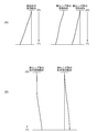
- FIG. 5A is a schematic diagram showing movement trajectories of the tube member and the focusing lens group with respect to the image plane during zooming
- FIG. 5B is a tube of the focusing lens group during zooming. It is a schematic diagram showing a relative movement locus to a member.
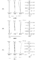
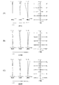
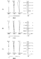
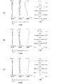
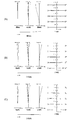
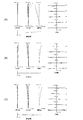
- 6(A), 6(B), and 6(C) show focusing at infinity at the wide-angle end state, the intermediate focal length state, and the telephoto end state of the variable power optical system according to Example 1, respectively.
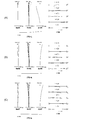
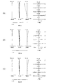
- 9 is a diagram of various types of aberrations in FIG. 7(A), 7(B), and 7(C) are respectively for wide-angle end state, intermediate focal length state, and telephoto end state of the variable power optical system according to Example 1 at short distance focusing.
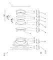
- 9 is a diagram of various types of aberrations in FIG. It is a figure which shows the lens structure of the variable power optical system which concerns on 2nd Example.
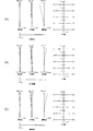
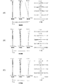
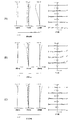
- 9(A), 9(B), and 9(C) respectively show focusing at infinity in the wide-angle end state, intermediate focal length state, and telephoto end state of the variable power optical system according to the second example.
- 9 is a diagram of various types of aberrations in FIG. 10(A), 10(B), and 10(C) respectively show the variable power optical system according to Example 2 at the wide-angle end state, the intermediate focal length state, and the telephoto end state when focusing on a short distance.
- 9 is a diagram of various types of aberrations in FIG. It is a figure which shows the lens structure of the variable power optical system which concerns on 3rd Example.
- FIG. 12(A), 12(B), and 12(C) respectively show focusing at infinity in the wide-angle end state, intermediate focal length state, and telephoto end state of the variable power optical system according to the third example.
- 9 is a diagram of various types of aberrations in FIG. 13(A), 13(B), and 13(C) respectively show the variable power optical system according to Example 3 at the wide-angle end state, the intermediate focal length state, and the telephoto end state when focusing on a short distance.
- 9 is a diagram of various types of aberrations in FIG. It is a figure which shows the lens structure of the variable power optical system which concerns on 4th Example.
- FIG. 16(A), 16(B), and 16(C) respectively show the variable power optical system according to Example 4 at the wide-angle end state, the intermediate focal length state, and the telephoto end state when focusing on a short distance.
- 9 is a diagram of various types of aberrations in FIG. It is a figure which shows the lens structure of the variable power optical system which concerns on 5th Example.
- FIG. 19(A), 19(B), and 19(C) respectively show the variable magnification optical system according to the fifth example at the wide-angle end state, the intermediate focal length state, and the telephoto end state at the short distance focusing.
- 9 is a diagram of various types of aberrations in FIG. It is a figure which shows the lens structure of the variable power optical system which concerns on 6th Example.
- 21(A), 21(B), and 21(C) show focusing at infinity in the wide-angle end state, intermediate focal length state, and telephoto end state of the variable power optical system according to the sixth example, respectively.
- 9 is a diagram of various types of aberrations in FIG. 22(A), 22(B), and 22(C) respectively show the variable power optical system according to the sixth example at the wide-angle end state, the intermediate focal length state, and the telephoto end state when focusing on a short distance.
- 9 is a diagram of various types of aberrations in FIG. It is a figure which shows the lens structure of the variable power optical system which concerns on 7th Example.
- FIG. 24(A), 24(B), and 24(C) respectively show the variable magnification optical system according to the seventh example at the wide-angle end state, the intermediate focal length state, and the telephoto end state at infinity.
- 9 is a diagram of various types of aberrations in FIG. 25(A), 25(B), and 25(C) respectively show the variable magnification optical system according to Example 7 at the wide-angle end state, the intermediate focal length state, and the telephoto end state at a short distance focus.
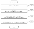
- 9 is a diagram of various types of aberrations in FIG. 6 is a flowchart showing a method of manufacturing the variable power optical system according to the first embodiment.
- variable power optical systems according to the first to fourth embodiments and optical devices equipped with the variable power optical systems will be described with reference to the drawings.
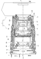
- a camera optical device including the variable power optical system according to the first to fourth embodiments will be described with reference to FIG.
- the camera 1 is a camera including a variable magnification optical system according to the first to fourth embodiments as a lens barrel 2.
- the camera 1 includes a lens barrel 2 and a camera body 3.
- the lens barrel 2 is provided with a lens mount LM at a base end portion (rear portion) on the image side, and is detachably attached to the camera body 3 by engaging with a body mount BM of the camera body 3.
- the subject side in the optical axis OA direction of the lens barrel 2 is referred to as the object side
- the camera body 3 side is referred to as the image side.
- the side away from the optical axis OA is called the outer diameter side
- the side approaching the optical axis OA is called the inner diameter side.
- the camera body 3 includes an image sensor 4 that converts an optical image into an electric signal, and image-processes image data captured by the image sensor 4 and records the image data in a recording unit (not shown).
- the lens barrel 2 is a so-called zoom lens (variable magnification optical system) having a plurality of lens groups and having a changeable focal length.
- a first lens group G1, a second lens group G2, a third lens group G3, a fourth lens group G4, a fifth lens group G5, and a sixth lens group are sequentially arranged from the object side.
- a lens group G6 and a seventh lens group G7 are arranged. At least a part of the first lens group G1, the second lens group G2, the third lens group G3, the fourth lens group G4, the fifth lens group G5, the sixth lens group G6, and the seventh lens group G7 has a variable power. Move during (zooming).
- the fifth lens group G5 and the sixth lens group G6 are focusing lens groups that move during focusing.
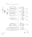
- the first lens group G1 is held by the first group frame 11.
- the outer periphery of the first group frame 11 is held by the first group sliding cylinder 12.
- the second lens group G2 is held by the second group frame 21.
- the third lens group G3 is held by the third group frame 31.
- the fourth lens group G4 is held by the fourth group frame 41.
- the fifth lens group G5 is held by the fifth group frame 51.
- the sixth lens group G6 is held by the sixth group frame 61.
- the seventh lens group G7 is held by the seventh group frame 71.
- the lens barrel 2 includes a first operating ring 81, an outer cam barrel 82, an inner cam barrel 83, an outer fixed barrel 84, an inner fixed barrel 85, and a second operating ring 86.
- a first operation ring 81 and a second operation ring 86 are rotatably provided on the outer peripheral portion of the outer fixed barrel 84 with respect to the outer fixed barrel 84.
- the first group sliding barrel 12 and the outer cam barrel 82 are arranged in order from the outer diameter side.
- the second group frame 21, the third group frame 31, the fourth group frame 41, the tubular member 100, and the seventh group frame 71 are arranged on the inner diameter side of the inner fixed barrel 85 in order from the front side.
- a fifth group frame 51 and a sixth group frame 61 are arranged in this order from the front side on the inner diameter side of the tubular member 100.
- An inner cam barrel 83 is arranged between the fourth group frame 41, the tubular member 100, the seventh group frame 71, and the inner fixed barrel 85.
- a plurality of cam grooves are formed in the outer cam barrel 82 and the inner cam barrel 83, and the cam followers of the corresponding lens group frames and tubular members are engaged with each other. Further, a plurality of rectilinear grooves are formed in the inner fixed barrel 85 and the outer fixed barrel 84 along the optical axis OA direction, and the cam followers and the tubular members of the corresponding lens group frames are engaged therewith.
- the drive mechanism for driving each lens group frame in the optical axis OA direction can be changed as appropriate.
- the first operation ring 81 is a so-called zoom ring and can be rotated by the user.
- the lens barrel 2 includes a first detection unit (not shown) that detects the rotation amount of the first operation ring 81.
- the first detection unit When detecting the rotation of the first operation ring 81, the first detection unit outputs the rotation amount and the rotation speed to the control unit (not shown) in the lens barrel 2.
- the control unit drives and controls a motor for changing the focal length (such as a fifth-group drive motor STM5 or a sixth-group drive motor STM6 described below) according to the rotation amount of the first operation ring 81.
- the second operation ring 86 can be rotated by the user, and the function operated by the rotation can be set on the lens barrel 2 or the camera body 3.
- the user can change the optical characteristics such as the focus position, the focal length, and the aperture value by rotating the second operation ring 86, for example.
- a second detection unit (not shown) that detects the rotation amount of the second operation ring 86 is provided on the inner diameter side of the second operation ring 86.
- the second detection unit detects the rotation amount and the rotation speed of the second operation ring 86 and outputs them to the control unit (not shown) in the lens barrel 2. ..
- the control unit drives and controls a motor for changing the optical characteristics (a drive motor STM5 for the fifth group, a drive motor STM6 for the sixth group, etc., which will be described later) according to the rotation amount of the second operation ring 86.
- the control unit also transmits information to and from the camera body 3 according to the rotation of the first operation ring 81 or the second operation ring 86, and determines the state of the lens barrel 2 (optical characteristics or operation state by the user). Send to 3.
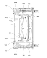
- the tubular member 100 includes a part of a fifth group driving unit 150 including a fifth group driving motor STM5 and a part of a sixth group driving unit 160 including a sixth group driving motor STM6.
- a pair of guide shafts 170 are provided.
- the fifth group driving unit 150 drives the fifth group frame 51 in the optical axis OA direction.
- the fifth-group drive unit 150 includes a fifth-group drive screw STM5 and a fifth-group lead screw 151 and a fifth-group rack 152.
- the fifth-group drive motor STM5 is, for example, a stepping motor, and is fixed to the tubular member 100.
- the fifth group lead screw 151 is formed in a shaft shape having a threaded portion and extending in the optical axis OA direction, and is connected to the output shaft of the fifth group drive motor STM5 to rotate.
- the fifth-group rack 152 is screwed with the thread portion of the fifth-group lead screw 151 and is connected to the fifth-group frame 51.
- the 6-group drive unit 160 drives the 6-group frame 61 in the optical axis OA direction.
- the 6-group drive unit 160 includes a 6-group drive screw STM6, a 6-group lead screw 161, and a 6-group rack 162.
- the sixth-group drive motor STM6 is, for example, a stepping motor, and is fixed to the tubular member 100.
- the sixth group lead screw 161 is formed in a shaft shape having a threaded portion and extending in the optical axis OA direction, and is connected to the output shaft of the sixth group drive motor STM6.
- the sixth group rack 162 is screwed with the thread portion of the sixth group lead screw 161, and is connected to the sixth group frame 61.
- the fifth-group drive motor STM5 and the sixth-group drive motor STM6 are arranged in the cylindrical member 100 at positions displaced by about 180° around the optical axis OA.
- the guide shaft 170 is formed in a shaft shape extending in the optical axis OA direction and is fixed to the tubular member 100.
- the guide shaft 170 engages with an engagement hole formed in the fifth group frame 51 to guide the fifth group frame 51 in the optical axis OA direction.
- the guide shaft 170 engages with an engagement hole formed in the sixth group frame 61 to guide the sixth group frame 61 straight in the optical axis OA direction.
- the fifth lens group G5 held by the fifth group frame 51 and the sixth lens group G6 held by the sixth group frame 61 are guided straight by the guide shaft 170 in the optical axis OA direction.
- the optical axis OA is applied to the fifth-group frame 51 via the fifth-group rack 152 screwed with the thread portion of the fifth-group lead screw 151.
- the driving force in the direction is transmitted.
- the fifth lens group G5 held by the fifth group frame 51 is guided straight in the optical axis OA direction by the guide shaft 170 so as not to rotate about the fifth group lead screw 151 as the central axis.
- the fifth lens group G5 can be moved relative to the tubular member 100 in the optical axis OA direction by the fifth group driving unit 150. This makes it possible for the fifth lens group G5 and the tubular member 100 to have different amounts of relative movement in the optical axis OA direction with respect to the image sensor 4 (image surface) during zooming.
- the sixth-group drive motor STM6 rotates the sixth-group lead screw 161
- the optical axis OA with respect to the sixth-group frame 61 is passed through the sixth-group rack 162 threadedly engaged with the thread portion of the sixth-group lead screw 161.
- the driving force in the direction is transmitted.
- the sixth lens group G6 held by the sixth group frame 61 is guided straight by the guide shaft 170 in the optical axis OA direction so as not to rotate about the sixth group lead screw 161 as the central axis.
- the sixth lens unit G6 can move the sixth lens group G6 relative to the tubular member 100 in the optical axis OA direction.
- the sixth lens group G6 and the tubular member 100 can have different amounts of relative movement in the optical axis OA direction with respect to the image sensor 4 (image surface) during zooming.
- the fifth lens unit G5 and the sixth lens unit G6 can be driven separately by the fifth lens unit driving unit 150 and the sixth lens unit driving unit 160. This makes it possible for the fifth lens group G5 and the sixth lens group G6 to differ in the relative movement amount in the optical axis OA direction with respect to the image sensor 4 (image surface) during zooming or focusing.
- the fifth-group drive motor STM5 and the sixth-group drive motor STM6 are, for example, stepping motors, but are not limited to these, and may be DC motors, voice coil motors, ultrasonic motors, or the like.
- the drive motor STM5 for the fifth group and the drive motor STM6 for the sixth group may use the same type of motor or different types of motors.
- the fifth-group drive motor STM5 and the sixth-group drive motor STM6 are arranged on the object side of the tubular member 100, but the arrangement of the fifth-group drive motor STM5 and the sixth-group drive motor STM6 can be appropriately changed.
- the fifth group drive motor STM5 may be arranged on the object side (or the image side) of the cylindrical member 100
- the sixth group drive motor STM6 may be arranged on the image side (or the object side) of the cylindrical member 100.
- one of the fifth-group drive motor STM5 and the sixth-group drive motor STM6 is arranged on the cylindrical member 100
- the other of the fifth-group drive motor STM5 and the sixth-group drive motor STM6 is arranged on a member different from the cylindrical member 100. It may be done.
- the lens barrel 2 since the two lens groups (G5, G6) that move during focusing are arranged in one tubular member 100, the lens barrel 2 can be miniaturized.
- the guide shaft 170 is fixed to the tubular member 100
- the guide shaft 170 is not limited to this, and may be fixed to a movable tubular member separately from the tubular member 100.
- the guide shaft 170 may be fixed to the fourth group frame 41, at least a part of which is arranged on the object side or the image side of the tubular member 100.
- the fifth lens group G5 held by the fifth group frame 51 and the sixth lens group G6 held by the sixth group frame 61 are guided straight by the guide shaft 170 in the optical axis OA direction, but the present invention is not limited to this.
- a cam follower and a straight groove may be used to guide straight in the optical axis OA direction.
- the pair of guide shafts 170 that linearly guide the fifth lens group G5 and the sixth lens group G6 are linearly guided.
- a pair of guide shafts for guiding may be provided.
- the fifth lens group G5 and the sixth lens group G6 are assumed to move independently in the optical axis OA direction, but the fifth lens group G5 and the sixth lens group G6 are integrated. It may be moved in the optical axis OA direction. Further, the fifth lens group G5 and the sixth lens group G6 may integrally move in the optical axis OA direction at a part of focusing from an object at infinity to a near object. When the fifth lens group G5 and the sixth lens group G6 move integrally in the optical axis OA direction, only one drive unit may be provided in the tubular member 100.
- the first group frame 11 (first group sliding cylinder 12 ), the second group frame 21, the third group frame 31, the fourth group frame 41, the tubular member 100, and the seventh group frame 71 of the first operation ring 81 during zooming.
- the outer cam barrel 82 and the inner cam barrel 83 which rotate due to the rotation, they are driven in the optical axis OA direction.
- the fifth group frame 51 is attached to the tubular member 100 by the fifth group drive unit 150 provided on the tubular member 100 in accordance with the rotation of the first operating ring 81 or the second operating ring 86. In contrast, it is driven in the optical axis OA direction.
- the sixth group frame 61 is also driven in the optical axis OA direction with respect to the tubular member 100 by the sixth group driving unit 160 provided in the tubular member 100 in response to the rotation of the first operating ring 81 or the second operating ring 86.
- the first lens group G1, the second lens group G2, the third lens group G3, the fourth lens group G4, the tubular member 100 and the seventh lens group G7 are mechanical when the first operating ring 81 is rotated.
- the fifth lens group G5 and the sixth lens group G6 are mechanically and electrically (motor drive control) driven in the optical axis OA direction when the first operating ring 81 is rotated, and the second operating ring G5.
- 86 is rotated and a focusing operation is instructed, it is electrically driven in the optical axis OA direction.
- the first lens group G1, the second lens group G2, the third lens group G3, the fourth lens group G4, the fifth lens group G5, the sixth lens group G6, and the seventh lens group G7 are At the time of doubling, it is driven in the optical axis OA direction.
- the fifth lens group G5 and the sixth lens group G6 are driven in the optical axis OA direction during focusing.
- the variable power lens group is driven in the optical axis OA direction by the cam function, but a drive unit (motor) for driving the variable power lens group in the optical axis OA direction may be provided.
- the camera 1 In such a camera 1, light from an unillustrated object (subject) is condensed by the lens barrel 2 and reaches the image sensor 4 of the camera body 3. Thereby, the light from the subject is captured by the image sensor 4, and the image data captured by the image sensor 4 is image-processed and recorded in a recording unit (not shown). In this way, the photographer can photograph the subject with the camera 1.
- the camera 1 is not limited to a digital single lens reflex camera, but may be a mirrorless camera or a compact digital camera.
- variable power optical system ZL(1) as an example of the variable power optical system ZL according to the first embodiment has a plurality of lens groups, and each adjacent lens at the time of variable power. Group spacing changes.
- the variable power optical system ZL(1) has a focusing lens group that moves during focusing, and an image side lens group that is arranged adjacent to the image side of the focusing lens group.
- variable power optical system ZL may be the variable power optical system ZL(2) shown in FIG. 8, the variable power optical system ZL(3) shown in FIG. 11, or the variable power optical system shown in FIG.
- the system ZL(4) may be used, or the variable power optical system ZL(7) shown in FIG. 23 may be used.
- variable power optical system ZL satisfies the following conditional expression (1).
- dL0t Distance on the optical axis between the focusing lens group and the image side lens group when focusing on an object at infinity in the telephoto end state
- dL1t Focusing when focusing on a short-distance object at the telephoto end state Distance on the optical axis between the lens group and the image-side lens group
- Conditional expression (1) is defined by the distance between the focusing lens group and the image-side lens group on the optical axis when focusing on an object at infinity in the telephoto end state, and the distance object (the object at the shortest distance). It defines the ratio of the distance between the focusing lens unit and the image-side lens unit on the optical axis when focusing.
- various aberrations such as spherical aberration and coma are good both when focusing on an object at infinity and when focusing on a near object at the telephoto end. Can be corrected to.
- the upper limit of conditional expression (1) is set to 0.900, 0.850, 0.800, 0.780, 0.750, 0.740, 0. It may be set to 0.730, 0.720, 0.710, 0.700, 0.695, or 0.690.
- the lower limit of conditional expression (1) is set to 0.150, 0.200, 0.250, 0.300, 0.350, 0.400, 0. .450, 0.500, 0.550, 0.600, 0.610, 0.620, 0.630, 0.640, 0.650, 0.660, and may be set to 0.665.
- the plurality of lens groups are arranged in order from the object side, the first lens group G1 having a positive refractive power and the second lens group G2 having a negative refractive power. And a third lens group G3 having a positive refractive power, a fourth lens group G4 having a positive refractive power, and a succeeding lens group GR, the succeeding lens group GR including the focusing lens group and the image side. It is desirable to have a lens group.
- variable power optical system ZL has at least five lens groups, and the distance between the lens groups changes during zooming. Therefore, it becomes possible to suppress the variation of aberration at the time of zooming from the wide-angle end state to the telephoto end state. Further, by disposing the focusing lens group in the succeeding lens group GR, the focusing lens group can be reduced in size and weight, and high-speed and quiet autofocus can be realized without increasing the size of the lens barrel. It will be possible.
- variable power optical system ZL(1) as an example of the variable power optical system ZL according to the second embodiment has a plurality of lens groups as shown in FIG. 1, and each of the adjacent lenses at the time of variable power. Group spacing changes.
- the variable power optical system ZL(1) is a focusing lens group, and is arranged on the image side of the first focusing lens group and the first focusing lens group that moves during focusing and is focused. And a second focusing lens unit that moves at the time.
- variable power optical system ZL may be the variable power optical system ZL(2) shown in FIG. 8, the variable power optical system ZL(3) shown in FIG. 11, or the variable power optical system shown in FIG. System ZL(7) may also be used.
- variable power optical system ZL satisfies the following conditional expression (2).
- dF0w distance on the optical axis between the first focusing lens group and the second focusing lens group when focusing on an object at infinity in the wide-angle end state
- dF1w focusing on a short-distance object in the wide-angle end state
- Conditional expression (2) is defined by the distance on the optical axis between the first focusing lens group and the second focusing lens group when focusing on an object at infinity in the wide-angle end state, and a short-distance object (closest object). It defines the ratio of the distance between the first focusing lens group and the second focusing lens group on the optical axis when focusing on an object (distance).
- various aberrations such as spherical aberration and coma are good both when focusing on an object at infinity and when focusing on a near object at the wide-angle end. Can be corrected to.
- conditional expression (2) If the corresponding value of the conditional expression (2) deviates from the above range, the distance between the focusing lens group and the image side lens group becomes unsuitable, and it becomes difficult to suppress aberration fluctuation.
- the upper limit values of conditional expression (2) are set to 0.950, 0.940, 0.930, 0.920, 0.910, 0.900, 0. It may be set to 0.895, 0.890, 0.885, 0.880, 0.875, or 0.870.
- the lower limit of conditional expression (2) is set to 0.200, 0.300, 0.400, 0.500, 0.550, 0.600, 0. .650, 0.700, 0.750, 0.780, 0.800, 0.810, 0.815, and even 0.820.
- the plurality of lens groups are arranged in order from the object side, the first lens group G1 having a positive refractive power and the second lens group G2 having a negative refractive power. And a third lens group G3 having a positive refractive power, a fourth lens group G4 having a positive refractive power, and a succeeding lens group GR, and the succeeding lens group GR is a first focusing lens group. , And a second focusing lens unit.
- variable power optical system ZL according to the second embodiment has at least five lens groups, and the distance between the lens groups changes during zooming. Therefore, it becomes possible to suppress the variation of aberration at the time of zooming from the wide-angle end state to the telephoto end state. Further, by disposing the focusing lens group in the succeeding lens group GR, the focusing lens group can be reduced in size and weight, and high-speed and quiet autofocus can be realized without increasing the size of the lens barrel. It will be possible.
- variable power optical system ZL(1) which is an example of the variable power optical system ZL according to the third embodiment, has a plurality of lens groups as shown in FIG. Group spacing changes.
- the variable power optical system ZL(1) includes a focusing lens group that moves at the time of focusing, and a tubular member to which a drive unit for moving the focusing lens group is fixed (for example, FIGS. 1 and 2). And the tubular member 100) shown in FIG. 1, the tubular member moves during zooming.
- the focusing lens group can be moved relative to the tubular member by the driving unit, and the direction in which the focusing lens group moves relative to the tubular member during zooming from the wide-angle end state to the telephoto end state is
- the moving amount of the lens which is opposite to the moving direction of the cylindrical member and is arranged on the object side or the image side of the focusing lens unit, at the time of zooming differs from the moving amount of the cylindrical member at the time of zooming. Therefore, the cylinder member can be moved regardless of the movement locus of the focusing lens group during zooming, and the degree of freedom in designing the movement locus of the cylinder member is improved.
- the optical performance is improved by moving the tubular member and the lenses before and after the tubular member along a movement trajectory that avoids a collision, and the distance between the tubular member and the lenses before and after the tubular member is set under a non-photographing condition (for example, a reduced tubular state).
- a non-photographing condition for example, a reduced tubular state.
- the moving direction of the tubular member with respect to the image plane is the first direction
- the relative moving direction of the focusing lens group with respect to the tubular member is the second direction. ..
- the first direction and the second direction are opposite to each other at least in part during zooming from the wide-angle end state to the telephoto end state.
- the first direction and the second direction may be opposite when zooming in all focal length regions from the wide-angle end state to the telephoto end state, and when zooming in some focal length regions.
- the focusing lens group may not move relative to the tubular member.
- the focal length region in which the first direction and the second direction are opposite to each other is the focal point in which the first direction and the second direction are the same direction or the focusing lens group does not move relative to the tubular member. More than the distance region is preferable.
- variable power optical system ZL according to the third embodiment may be the variable power optical system ZL(2) shown in FIG. 8, the variable power optical system ZL(3) shown in FIG. 11, or the variable power optical system shown in FIG. System ZL(4) may also be used.
- the variable power optical system ZL according to the third embodiment may be the variable power optical system ZL(5) shown in FIG. 17, the variable power optical system ZL(6) shown in FIG. 20, or the variable power shown in FIG.
- the double optical system ZL(7) may be used.
- variable power optical system ZL satisfies the following conditional expression (3).
- dA the amount of movement of the focusing lens unit with respect to the image plane during zooming from the wide-angle end state to the telephoto end state (the amount of movement to the object side is set to +, and The sign of the amount of movement is-)
- dB Amount of movement of the cylindrical member with respect to the image surface during zooming from the wide-angle end state to the telephoto end state (the sign of the amount of movement to the object side is +, the sign of the amount of movement to the image side is To-)
- Conditional expression (3) is an amount of movement of the focusing lens group with respect to the image plane and a movement of the cylindrical member with respect to the image plane during zooming from the wide-angle end state to the telephoto end state. It defines the ratio to the quantity.
- conditional expression (3) it is possible to realize the miniaturization of the lens barrel while satisfactorily correcting various aberrations such as field curvature and coma.
- the moving amount of the focusing lens unit is the moving amount of the second focusing lens unit.
- conditional expression (3) If the corresponding value of the conditional expression (3) deviates from the above range, the positional relationship between the focusing lens group and the tubular member becomes unsuitable, so that the lens barrel can be downsized while suppressing the aberration variation. It will be difficult.
- the upper limit of conditional expression (3) By setting the upper limit of conditional expression (3) to 1.950, the effect of this embodiment can be made more reliable.
- the upper limit values of conditional expression (3) are set to 1.900, 1.800, 1.700, 1.600, 1.500, 1.400, 1 .300, 1.200, 1.100, 1.000, 0.980, and even 0.950.
- the lower limit of conditional expression (3) is set to ⁇ 0.100, 0.100, 0.200, 0.300, 0.400, 0.500, It may be set to 0.550, 0.600, 0.650, 0.700, 0.710, and even 0.720.
- variable power optical system ZL(1) which is an example of the variable power optical system ZL according to the fourth embodiment, has a plurality of lens groups as shown in FIG. Group spacing changes.
- the variable power optical system ZL(1) includes a focusing lens group that moves at the time of focusing, and a tubular member to which a drive unit for moving the focusing lens group is fixed (for example, FIGS. 1 and 2). And the tubular member 100) shown in FIG. 1, the tubular member moves during zooming.
- the focusing lens group can be moved relative to the tubular member by the drive unit, and the lens is not fixed to the tubular member.
- variable power optical system ZL according to the fourth embodiment may be the variable power optical system ZL(2) shown in FIG. 8, the variable power optical system ZL(3) shown in FIG. 11, or the variable power optical system shown in FIG. System ZL(4) may also be used.
- the variable power optical system ZL according to the fourth embodiment may be the variable power optical system ZL(5) shown in FIG. 17, the variable power optical system ZL(6) shown in FIG. 20, or the variable power shown in FIG.
- the double optical system ZL(7) may be used.
- variable power optical system ZL according to the fourth embodiment satisfies the following conditional expression (3) described above.
- conditional expression (3) By satisfying the conditional expression (3), it is possible to realize the miniaturization of the lens barrel while satisfactorily correcting various aberrations such as field curvature and coma as in the third embodiment.
- the upper limit values of conditional expression (3) are set to 1.900, 1.800, 1.700, 1.600, 1.500, 1.400, 1 .300, 1.200, 1.100, 1.000, 0.980, and even 0.950. Further, by setting the lower limit of conditional expression (3) to ⁇ 0.500, the effect of this embodiment can be made more reliable.
- the lower limit of conditional expression (3) is set to ⁇ 0.100, 0.100, 0.200, 0.300, 0.400, 0.500, It may be set to 0.550, 0.600, 0.650, 0.700, 0.710, and even 0.720.
- the plurality of lens groups has a first lens group G1 having a positive refractive power and arranged in order from the object side, and a negative refractive power.
- the second lens group G2, the third lens group G3 having a positive refractive power, the fourth lens group G4 having a positive refractive power, and the succeeding lens group GR are included, and the succeeding lens group GR is a focusing lens. It is desirable to have a group.
- variable power optical system ZL has at least five lens groups, and the distance between the lens groups changes during zooming. Therefore, it becomes possible to suppress the variation of aberration at the time of zooming from the wide-angle end state to the telephoto end state. Further, by disposing the focusing lens group in the succeeding lens group GR, the focusing lens group can be reduced in size and weight, and high-speed and quiet autofocus can be realized without increasing the size of the lens barrel. It will be possible.
- variable power optical system ZL has an image side lens group disposed adjacent to the image side of the focusing lens group, and the focusing lens group at the time of zooming. It is preferable that the distance between the lens group and the image-side lens group is changed and the following conditional expression (4) is satisfied.
- dE the amount of movement of the image-side lens unit relative to the image plane during zooming from the wide-angle end state to the telephoto end state (the amount of movement to the object side is defined as +, and The sign of the amount of movement is-)
- Conditional expression (4) is an amount of movement of the cylindrical member with respect to the image surface and an amount of movement of the image side lens unit with respect to the image surface during zooming from the wide-angle end state to the telephoto end state. It defines the ratio with.
- conditional expression (4) If the corresponding value of the conditional expression (4) deviates from the above range, the positional relationship between the focusing lens group and the tubular member becomes unsuitable, so that the lens barrel can be downsized while suppressing the aberration variation. It will be difficult.
- the upper limit of conditional expression (4) By setting the upper limit of conditional expression (4) to 1.450, the effect of this embodiment can be made more reliable.
- the upper limit values of conditional expression (4) are set to 1.400, 1.350, 1.300, 1.250, 1.200, 1.150, 1. .120, 1.100, 1.080, and even 1.050.
- the lower limit of conditional expression (4) is set to ⁇ 0.100, 0.100, 0.200, 0.300, 0.400, 0.500, It may be set to 0.550, 0.600, 0.650, 0.700, or 0.750.
- variable power optical system ZL has an object side lens group disposed adjacent to the object side of the focusing lens group, and at the time of zooming, the object side lens group. It is preferable that the distance between the focusing lens group and the focusing lens group changes, and the following conditional expression (5) is satisfied.
- dD the amount of movement of the object-side lens unit relative to the image plane during zooming from the wide-angle end state to the telephoto end state (the amount of movement to the object side is defined as +, and The sign of the amount of movement is-)
- Conditional expression (5) is an amount of movement of the cylindrical member with respect to the image surface and an amount of movement of the object-side lens unit with respect to the image surface during zooming from the wide-angle end state to the telephoto end state. It defines the ratio with.
- the upper limit of conditional expression (5) is set to 0.900, 0.850, 0.800, 0.750, 0.700, 0.690, 0. It may be set to .680, 0.670, or 0.665.
- the lower limit of conditional expression (5) is set to ⁇ 0.100, 0.100, 0.200, 0.300, 0.400, 0.500, It may be set to 0.510, 0.520, 0.530, 0.540, or even 0.550.
- the drive unit be a stepping motor. Accordingly, the focusing lens group can be moved in the optical axis direction as needed even during zooming, and the optical performance can be further improved.
- the variable power optical system ZL according to the third embodiment and the fourth embodiment includes, as a focusing lens group, a first focusing lens group that moves during focusing and an image side of the first focusing lens group. And a second focusing lens group which is disposed at a position and moves at the time of focusing, and a movement locus of the first focusing lens group at the time of zooming, and a zooming path of the second focusing lens group. It is desirable that the movement locus at the time of is different. This makes it possible to excellently correct various aberrations such as field curvature and spherical aberration.
- the first drive unit for moving the first focusing lens group and the second focusing lens group are moved in the tubular member. It is desirable that the second driving portion for fixing the fixed portion be fixed. Thereby, the fixing member of the first driving unit and the fixing member of the second driving unit can be used in common, and the lens barrel can be prevented from becoming large.
- a guide shaft for example, a guide shaft that linearly guides the first focusing lens group and the second focusing lens group in the optical axis direction on the tubular member.
- the guide shaft 170 shown in FIGS. 2 and 3 is preferably fixed.
- the fixing member for the linear guide shaft of the first focusing lens group and the fixing member for the linear guide shaft of the second focusing lens group can be used together, and the lens barrel can be prevented from becoming large. it can.
- variable power optical system ZL as a focusing lens group, a first focusing lens group that moves at the time of focusing, and an image side of the first focusing lens group are arranged. And a second focusing lens group that moves during focusing, the first focusing lens group and the second focusing lens group have positive refractive power, and the following conditional expression ( It is desirable to satisfy 6).
- fF1 focal length of the first focusing lens unit
- fF2 focal length of the second focusing lens unit
- Conditional expression (6) defines the ratio between the focal length of the first focusing lens unit and the focal length of the second focusing lens unit.
- the refracting power of the second focusing lens unit becomes too strong, so that fluctuations of various aberrations such as spherical aberration during focusing can be suppressed. It will be difficult.
- the upper limit of conditional expression (6) is set to 2.50, 2.30, 2.20, 2.10, 2.00, 1.90, 1, It may be set to 0.80, 1.70, 1.60, or 1.50.
- the refracting power of the first focusing lens unit becomes too strong, so that fluctuations of various aberrations such as spherical aberration during focusing can be suppressed. It will be difficult.
- the lower limit values of conditional expression (6) are set to 0.28, 0.30, 0.33, 0.35, 0.38, 0.40, 0. It may be set to 0.43, 0.45, 0.48, or 0.50.
- variable power optical system ZL as a focusing lens group, a first focusing lens group that moves at the time of focusing, and an image side of the first focusing lens group are arranged. And a second focusing lens group that moves during focusing, the first focusing lens group and the second focusing lens group have positive refractive power, and the following conditional expression ( It is desirable to satisfy 7).
- MTF1 Absolute value of the amount of movement of the first focusing lens unit when focusing from an infinite object to a short-distance object in the telephoto end state
- MTF2 focusing from an infinite object to a short-distance object in the telephoto end state Absolute value of the amount of movement of the second focusing lens unit when moving
- Conditional expression (7) is an absolute value of the amount of movement of the first focusing lens unit when focusing from an infinitely distant object to a short-distance object (object at the shortest distance) in the telephoto end state, and in the telephoto end state. It defines the ratio of the moving amount of the second focusing lens unit to the absolute value when focusing from an object at infinity to an object at a short distance (object at the closest distance).
- the upper limit of conditional expression (7) is set to 2.80, 2.70, 2.60, 2.50, 2.40, 2.30, 2. .20, 2.10, or even 2.00.
- conditional expression (7) If the corresponding value of the conditional expression (7) is less than the lower limit value, the amount of movement of the second focusing lens unit becomes too large, so fluctuations of various aberrations such as spherical aberration during focusing can be suppressed. It will be difficult.
- the lower limit values of conditional expression (7) are set to 0.30, 0.35, 0.40, 0.45, 0.50, 0.55, 0. It may be set to 0.60, 0.65, or 0.70.
- variable power optical system ZL as a focusing lens group, a first focusing lens group that moves at the time of focusing, and an image side of the first focusing lens group are arranged. And a second focusing lens group that moves during focusing, the first focusing lens group and the second focusing lens group have positive refractive power, and the following conditional expression ( It is desirable to satisfy 8).
- ⁇ TF1 lateral magnification of the first focusing lens group when focusing on an object at infinity in the telephoto end state
- ⁇ TF2 of the second focusing lens group when focusing on an object at infinity at the telephoto end state
- Conditional expression (8) is the lateral magnification of the first focusing lens unit when focusing on an object at infinity in the telephoto end state, and the second focusing when focusing on an object at infinity at the telephoto end state. It defines the ratio to the lateral magnification of the lens group.
- conditional expression (8) exceeds the upper limit value, the lateral magnification of the first focusing lens unit becomes too large, so that fluctuations of various aberrations such as spherical aberration during focusing can be suppressed. It will be difficult.
- the upper limit of conditional expression (8) is set to 4.50, 4.30, 4.00, 3.80, 3.50, 3.30, and 3. It may be set to 0.00, 2.80, 2.50, 2.30, 2.00, 1.80, or 1.50.
- the corresponding value of the conditional expression (8) is less than the lower limit value, the lateral magnification of the second focusing lens unit becomes too large, so that fluctuations of various aberrations such as spherical aberration at the time of focusing can be suppressed. It will be difficult.
- the lower limit values of conditional expression (8) are set to 0.30, 0.35, 0.40, 0.45, 0.50, 0.55, 0. It may be set to 0.60, 0.65, or 0.70.
- variable power optical system ZL as a focusing lens group, a first focusing lens group that moves at the time of focusing, and an image side of the first focusing lens group are arranged. And a second focusing lens group that moves during focusing, and the first focusing lens group and the second focusing lens group have positive refracting power, and the first focusing lens group It is desirable that the lens group and the second focusing lens group be adjacent to each other. This makes it possible to suppress variations in various aberrations such as spherical aberration when focusing from an infinitely distant object to a short-distance object.
- the focusing lens group be composed of three or less single lenses. This makes it possible to reduce the size and weight of the focusing lens unit.
- variable power optical system ZL it is preferable that at least one of the focusing lens groups has a single lens having a negative refractive power. This makes it possible to suppress variations in various aberrations such as spherical aberration when focusing from an infinitely distant object to a short-distance object.
- variable power optical systems ZL it is desirable that the focusing lens group be arranged on the image side of the aperture stop S. This makes it possible to reduce the size and weight of the focusing lens unit.
- variable power optical systems ZL according to the first to fourth embodiments satisfy the following conditional expression (9).
- fF focal length of the focusing lens unit having the strongest refractive power in the focusing lens unit
- ft focal length of the variable power optical system ZL in the telephoto end state
- Conditional expression (9) defines the ratio of the focal length of the focusing lens unit having the strongest refractive power among the focusing lens units and the focal length of the variable magnification optical system ZL in the telephoto end state.
- the corresponding value of the conditional expression (9) exceeds the upper limit value, the refracting power of the focusing lens group becomes too weak, so that the amount of movement of the focusing lens group at the time of focusing becomes large and the lens barrel becomes large. ..
- the upper limit of conditional expression (9) is set to 3.60, 3.40, 3.20, 3.00, 2.80, 2.60, 2 .40, 2.20, or even 2.00.
- the corresponding value of the conditional expression (9) When the corresponding value of the conditional expression (9) is lower than the lower limit value, the refractive power of the focusing lens unit becomes too strong, so that it becomes difficult to suppress variations in various aberrations such as spherical aberration during focusing. ..
- the lower limit of conditional expression (9) By setting the lower limit of conditional expression (9) to 0.23, the effect of this embodiment can be made more reliable. In order to further secure the effect of the present embodiment, even if the lower limit value of the conditional expression (9) is set to 0.25, 0.28, 0.30, 0.33, and further 0.35. Good.
- step ST1 a plurality of lens groups are arranged (step ST1). Then, the configuration is such that the distance between adjacent lens groups changes during zooming (step ST2). Further, a focusing lens group that moves during focusing is arranged, and an image side lens group is arranged adjacent to the image side of the focusing lens group (step ST3). Further, each lens is arranged in the lens barrel so as to satisfy at least the conditional expression (1) (step ST4).
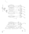
- variable power optical system ZL according to each embodiment will be described below with reference to the drawings. 4, FIG. 8, FIG. 11, FIG. 14, FIG. 17, FIG. 20, and FIG. 23 show the configuration of variable magnification optical systems ZL ⁇ ZL(1) to ZL(7) ⁇ according to the first to seventh examples, and It is sectional drawing which shows refractive power distribution.
- the first to third examples and the seventh example are examples corresponding to the first to fourth embodiments, and the fourth example corresponds to the first embodiment and the third to fourth embodiments.
- Examples 5 to 6 are examples corresponding to the third to fourth embodiments.
- the moving direction along the optical axis of each lens group when zooming from the wide-angle end state (W) to the telephoto end state (T) is indicated by an arrow.
- the moving direction when the focusing lens group focuses on an object at a short distance from infinity is indicated by an arrow together with the character "focus".
- each lens group is represented by a combination of reference numeral G and a numeral
- each lens is represented by a combination of reference numeral L and a numeral.
- the lens groups and the like are represented independently by using combinations of symbols and numbers for each embodiment. Therefore, even if the same combination of reference numerals and numbers is used between the embodiments, it does not mean that they have the same configuration.
- f is the focal length of the entire lens system
- FNO is the F number
- 2 ⁇ is the angle of view (unit is ° (degrees)
- ⁇ is the half angle of view
- Ymax is the maximum image height.
- TL represents the distance from the lens front surface to the final lens surface on the optical axis when focused on infinity, plus BF.
- BF is the image from the final lens surface on the optical axis when focused on infinity.
- the air-converted distance (back focus) to the surface I is shown. Note that these values are shown for each of the wide-angle end (W), the intermediate focal length (M), and the telephoto end (T) in each variable power state.
- MTF1 is the absolute amount of movement of the first focusing lens unit when focusing from an object at infinity to a short-distance object (object at the shortest distance) in the telephoto end state. Indicates a value.
- MTF2 represents the absolute value of the amount of movement of the second focusing lens group when focusing from an infinitely distant object to a short-distance object (object at the shortest distance) in the telephoto end state.
- ⁇ TF1 represents the lateral magnification of the first focusing lens unit when focusing on an object at infinity in the telephoto end state.
- ⁇ TF2 represents the lateral magnification of the second focusing lens unit when focusing on an object at infinity in the telephoto end state.
- dA represents the amount of movement of the focusing lens group with respect to the image plane during zooming from the wide-angle end state to the telephoto end state (+ is the sign of the amount of movement toward the object side, and The sign of the amount of movement of is-).
- dB indicates the amount of movement of the tubular member with respect to the image plane during zooming from the wide-angle end state to the telephoto end state.
- dD represents the amount of movement of the object-side lens group with respect to the image plane during zooming from the wide-angle end state to the telephoto end state.
- dE represents the amount of movement of the image-side lens unit with respect to the image surface during zooming from the wide-angle end state to the telephoto end state.
- the surface number indicates the order of the optical surface from the object side along the traveling direction of the light beam, and R represents the radius of curvature of each optical surface (the surface whose center of curvature is located on the image side).
- D is a surface distance that is a distance on the optical axis from each optical surface to the next optical surface (or image surface)
- nd is a refractive index of the material of the optical member with respect to d-line
- ⁇ d is an optical value.
- the Abbe numbers of the material of the member with respect to the d-line are shown respectively.
- the radius of curvature “ ⁇ ” indicates a plane or an aperture, and (stop S) indicates an aperture stop.
- X(y) is the distance (zag amount) along the optical axis from the tangent plane at the apex of the aspherical surface to the position on the aspherical surface at the height y
- R is the radius of curvature of the reference spherical surface (paraxial radius of curvature).
- ⁇ is a conic constant
- Ai is an i-th order aspherical coefficient.
- the quadratic aspherical coefficient A2 is 0, and the description thereof is omitted.
- the [Lens group data] table shows the starting surface (the surface closest to the object) and the focal length of each lens group.
- the table of [Variable spacing data] shows the surface spacing at the surface number where the surface spacing is “variable” in the table showing [lens specifications].
- W wide-angle end
- M intermediate focal length
- T telephoto end
- the table of [Values corresponding to conditional expressions] shows the values corresponding to each conditional expression.
- the focal length f, radius of curvature R, surface distance D, and other lengths listed are generally “mm” unless otherwise specified, but the optical system is enlarged proportionally. Alternatively, the same optical performance can be obtained even if the proportion is reduced, and the present invention is not limited to this.
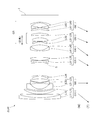
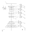
- FIG. 4 is a diagram showing a lens configuration of a variable power optical system according to the first example.
- the variable power optical system ZL(1) according to the first example includes a first lens group G1 having a positive refractive power, a second lens group G2 having a negative refractive power, and an aperture arranged in order from the object side.
- the lens group including the fifth lens group G5, the sixth lens group G6, and the seventh lens group G7 corresponds to the succeeding lens group GR, and has a negative refracting power as a whole.
- the symbol (+) or ( ⁇ ) attached to each lens group symbol indicates the refractive power of each lens group, and this is the same in all the examples below.
- the first lens group G1 includes, in order from the object side, a positive lens cemented with a negative meniscus lens L11 having a convex surface facing the object side and a positive meniscus lens L12 having a convex surface facing the object side, and a convex surface facing the object side. And a positive meniscus lens L13.
- the second lens group G2 includes, in order from the object side, a negative meniscus lens L21 having a convex surface facing the object side, a biconcave negative lens L22, a biconvex positive lens L23, and a concave surface facing the object side. And a negative meniscus lens L24 facing the lens.
- the negative meniscus lens L21 has an aspherical lens surface on the object side.
- the third lens group G3 is composed of a positive meniscus lens L31 having a convex surface facing the object side and a biconvex positive lens L32 arranged in order from the object side.
- the aperture stop S is provided near the object side of the third lens group G3, and moves together with the third lens group G3 during zooming.
- the positive meniscus lens L31 has an aspherical lens surface on the object side.
- the fourth lens group G4 is composed of a cemented positive lens including a negative meniscus lens L41 having a convex surface directed toward the object side and a biconvex positive lens L42.
- the fifth lens group G5 is composed of a negative meniscus lens L51 having a concave surface facing the object side and a biconvex positive lens L52 arranged in order from the object side.
- the sixth lens group G6 is composed of a positive meniscus lens L61 having a concave surface facing the object side.
- the image-side lens surface of the positive meniscus lens L61 is aspheric.
- the seventh lens group G7 is composed of a positive meniscus lens L71 having a concave surface facing the object side, a biconcave negative lens L72, and a negative meniscus lens L73 having a concave surface facing the object side, which are arranged in order from the object side. To be done.
- the negative lens L72 has an aspherical lens surface on the object side.
- the image plane I is disposed on the image side of the seventh lens group G7.
- the fifth lens group G5 and the sixth lens group G6 are independently moved to the object side, thereby focusing from a long-distance object to a short-distance object (infinite object to finite object). Done. That is, the fifth lens group G5 corresponds to the first focusing lens group, and the sixth lens group G6 corresponds to the second focusing lens group.
- the fourth lens group G4 corresponds to the object side lens group, and the seventh lens group G7 corresponds to the image side lens group.
- the cylinder member 100 is arranged between the fourth lens group G4 and the seventh lens group G7, and the fifth lens group G5 and , And a sixth lens group G6.
- the tubular member 100 moves to the object side.
- the fifth lens group G5 and the sixth lens group G6 can be moved relative to the tubular member 100 in the optical axis direction by the fifth group driving motor and the sixth group driving motor fixed to the tubular member 100.
- the fifth lens group G5, the sixth lens group G6, and the tubular member 100 make it possible for the fifth lens group G5, the sixth lens group G6, and the tubular member 100 to have different relative movement amounts in the optical axis direction with respect to the image plane I during zooming. Further, at the time of zooming or focusing, the relative movement amount in the optical axis direction with respect to the image plane I can be made different between the fifth lens group G5 and the sixth lens group G6.
- FIG. 5(A) On the left side of FIG. 5(A), a movement locus of the tubular member 100 with respect to the image plane when zooming from the wide-angle end state (W) to the telephoto end state (T) is shown.
- the movement of the focusing lens group (the fifth lens group G5 and the sixth lens group G6) with respect to the image plane when changing the magnification from the wide-angle end state (W) to the telephoto end state (T). Shows the trajectory.
- FIG. 5B shows the relative position of the focusing lens group (the fifth lens group G5 and the sixth lens group G6) with respect to the tubular member 100 when zooming from the wide-angle end state (W) to the telephoto end state (T). Shows a moving path.
- the cylindrical member 100 when the magnification is changed from the wide-angle end state to the telephoto end state, the cylindrical member 100 is arranged at a position close to the image-side end of the lens arranged on the object side of the cylindrical member 100 in the wide-angle end state.
- the tubular member 100 In the telephoto end state, the tubular member 100 is arranged at a position close to the object side end of the lens arranged on the image plane side. That is, the tubular member 100 is close to the lens arranged on one of the object side and the image plane side of the tubular member 100 in the first focal length state, and is in the second focal length state different from the first focal length state. Is close to a lens arranged on the other side of the cylindrical member 100 on the object side and the image plane side.
- the tubular member 100 moves so as to avoid collision with the front and rear lenses that move toward the tubular member 100.
- the tubular member 100 moves so as to avoid a collision with the fourth lens group G4 in the wide-angle end state and a collision with the seventh lens group G7 in the telephoto end state.
- the focusing lens group (fifth lens group G5 and sixth lens group G6) is movable relative to the tubular member 100, and each aberration can be corrected by appropriately moving in each focal length state.
- the tubular member 100 moves toward the object side, while the focusing lens group has a fixed position with respect to the tubular member 100 or moves toward the image plane side with respect to the tubular member 100.
- the focusing lens group can be moved by a smaller amount than the cylindrical member 100, and each aberration can be corrected.
- the focusing lens group is configured to fix the position with respect to the tubular member 100 or to move relative to the direction opposite to the moving direction of the tubular member 100 during zooming. The relative movement may be performed in the same direction. Further, when the magnification is changed, the focusing lens group moves to the object side with respect to the image plane, but may move to the image plane side with respect to the image plane.
- Table 1 below lists values of specifications of the variable power optical system according to the first example.
- 6(A), 6(B), and 6(C) show focusing at infinity at the wide-angle end state, the intermediate focal length state, and the telephoto end state of the variable power optical system according to Example 1, respectively.
- 9 is a diagram of various types of aberrations in FIG. 7(A), 7(B), and 7(C) are respectively for wide-angle end state, intermediate focal length state, and telephoto end state of the variable power optical system according to Example 1 at short distance focusing.
- 9 is a diagram of various types of aberrations in FIG.
- FNO indicates the F number
- Y indicates the image height
- the spherical aberration diagram shows the F number value corresponding to the maximum aperture
- the astigmatism diagram and the distortion diagram show the maximum image height
- the lateral aberration diagram shows the image height value.
- NA represents the numerical aperture
- Y represents the image height
- the spherical aberration diagram shows the numerical aperture value corresponding to the maximum aperture
- the astigmatism diagram and the distortion diagram show the maximum image height
- the lateral aberration diagram shows the image height value.
- the solid line shows the sagittal image plane
- the broken line shows the meridional image plane.
- variable power optical system according to the first example has excellent imaging performance by satisfactorily correcting various aberrations from the wide-angle end state to the telephoto end state, and further when focusing on a short distance. It can be seen that also has excellent imaging performance.
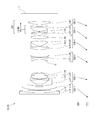
- FIG. 8 is a diagram showing a lens configuration of a variable power optical system according to the second example.
- the variable power optical system ZL(2) according to the second example includes a first lens group G1 having a positive refractive power, a second lens group G2 having a negative refractive power, and an aperture arranged in order from the object side.
- the lens group including the fifth lens group G5, the sixth lens group G6, and the seventh lens group G7 corresponds to the succeeding lens group GR, and has a negative refracting power as a whole.
- the first lens group G1 includes, in order from the object side, a positive lens cemented with a negative meniscus lens L11 having a convex surface facing the object side and a positive meniscus lens L12 having a convex surface facing the object side, and a convex surface facing the object side. And a positive meniscus lens L13.
- the second lens group G2 includes, in order from the object side, a negative meniscus lens L21 having a convex surface facing the object side, a biconcave negative lens L22, a biconvex positive lens L23, and a concave surface facing the object side. And a negative meniscus lens L24 facing the lens.
- the negative meniscus lens L21 has an aspherical lens surface on the object side.
- the third lens group G3 is composed of a biconvex positive lens L31 and a biconvex positive lens L32, which are arranged in order from the object side.
- the aperture stop S is provided near the object side of the third lens group G3, and moves together with the third lens group G3 during zooming.
- the lens surface of the positive lens L31 on the object side is an aspherical surface.
- the fourth lens group G4 is composed of a cemented positive lens including a negative meniscus lens L41 having a convex surface directed toward the object side and a biconvex positive lens L42.
- the fifth lens group G5 is composed of a negative meniscus lens L51 having a concave surface facing the object side and a biconvex positive lens L52 arranged in order from the object side.
- the sixth lens group G6 is composed of a positive meniscus lens L61 having a concave surface facing the object side.
- the image-side lens surface of the positive meniscus lens L61 is aspheric.
- the seventh lens group G7 is composed of a positive meniscus lens L71 having a concave surface facing the object side, a biconcave negative lens L72, and a negative meniscus lens L73 having a concave surface facing the object side, which are arranged in order from the object side. To be done.
- the negative lens L72 has an aspherical lens surface on the object side.
- the image plane I is disposed on the image side of the seventh lens group G7.
- the fifth lens group G5 and the sixth lens group G6 are independently moved to the object side, thereby focusing from a long-distance object to a short-distance object (infinite object to finite object). Done. That is, the fifth lens group G5 corresponds to the first focusing lens group, and the sixth lens group G6 corresponds to the second focusing lens group.
- the fourth lens group G4 corresponds to the object side lens group, and the seventh lens group G7 corresponds to the image side lens group.
- a tubular member (for example, the tubular member 100 shown in FIGS. 1 and 2) is disposed between the fourth lens group G4 and the seventh lens group G7, and the inner diameter side of the tubular member Further, a fifth lens group G5 and a sixth lens group G6 are arranged.
- the fifth lens group G5 and the sixth lens group G6 are relatively movable in the optical axis direction with respect to the tubular member by the fifth group driving motor and the sixth group driving motor fixed to the tubular member.
- the fifth lens group G5 and the sixth lens group G6 and the tubular member make different relative movement amounts in the optical axis direction with respect to the image plane I during zooming. Further, at the time of zooming or focusing, the relative movement amount in the optical axis direction with respect to the image plane I can be made different between the fifth lens group G5 and the sixth lens group G6.
- Table 2 below lists values of specifications of the variable power optical system according to the second example.
- 9(A), 9(B), and 9(C) respectively show the zoom optical system according to the second example at the wide-angle end state, the intermediate focal length state, and the telephoto end state at infinity.
- 9 is a diagram of various types of aberrations in FIG. 10(A), 10(B), and 10(C) respectively show the variable power optical system according to Example 2 at the wide-angle end state, the intermediate focal length state, and the telephoto end state when focusing on a short distance.
- 9 is a diagram of various types of aberrations in FIG. From the various aberration diagrams, the variable power optical system according to the second example has excellent imaging performance by satisfactorily correcting various aberrations from the wide-angle end state to the telephoto end state, and further when focusing on a short distance. It can be seen that also has excellent imaging performance.
- FIG. 11 is a diagram showing a lens configuration of a variable power optical system according to the third example.
- the variable power optical system ZL(3) according to the third example includes, in order from the object side, a first lens group G1 having a positive refractive power, a second lens group G2 having a negative refractive power, and an aperture.
- the lens group including the fifth lens group G5, the sixth lens group G6, and the seventh lens group G7 corresponds to the succeeding lens group GR, and has a negative refracting power as a whole.
- the first lens group G1 includes, in order from the object side, a cemented positive lens composed of a negative meniscus lens L11 having a convex surface facing the object side and a biconvex positive lens L12, and a positive meniscus lens having a convex surface facing the object side. And L13.
- the second lens group G2 includes, in order from the object side, a negative meniscus lens L21 having a convex surface facing the object side, a biconcave negative lens L22, a biconvex positive lens L23, and a concave surface facing the object side. And a negative meniscus lens L24 facing the lens.
- the negative meniscus lens L21 has an aspherical lens surface on the object side.
- the third lens group G3 is composed of a positive meniscus lens L31 having a convex surface facing the object side and a biconvex positive lens L32 arranged in order from the object side.
- the aperture stop S is provided near the object side of the third lens group G3, and moves together with the third lens group G3 during zooming.
- the positive meniscus lens L31 has an aspherical lens surface on the object side.
- the fourth lens group G4 is composed of a cemented positive lens including a negative meniscus lens L41 having a convex surface directed toward the object side and a biconvex positive lens L42.
- the fifth lens group G5 is composed of a negative meniscus lens L51 having a concave surface facing the object side and a biconvex positive lens L52 arranged in order from the object side.
- the sixth lens group G6 is composed of a positive meniscus lens L61 having a concave surface facing the object side.
- the image-side lens surface of the positive meniscus lens L61 is aspheric.
- the seventh lens group G7 includes, in order from the object side, a negative meniscus lens L71 having a convex surface directed toward the object side, a positive meniscus lens L72 having a concave surface directed toward the object side, and a negative meniscus lens having a concave surface directed toward the object side. And L73.
- the negative meniscus lens L73 has an aspherical lens surface on the object side.
- the image plane I is disposed on the image side of the seventh lens group G7.
- the fifth lens group G5 and the sixth lens group G6 are independently moved to the object side, thereby focusing from a long-distance object to a short-distance object (infinite object to finite object). Done. That is, the fifth lens group G5 corresponds to the first focusing lens group, and the sixth lens group G6 corresponds to the second focusing lens group.
- the fourth lens group G4 corresponds to the object side lens group, and the seventh lens group G7 corresponds to the image side lens group.
- a tubular member (for example, the tubular member 100 shown in FIGS. 1 and 2) is arranged between the fourth lens group G4 and the seventh lens group G7, and the inner diameter side of the tubular member Further, a fifth lens group G5 and a sixth lens group G6 are arranged.
- the fifth lens group G5 and the sixth lens group G6 are relatively movable in the optical axis direction with respect to the tubular member by the fifth group driving motor and the sixth group driving motor fixed to the tubular member.
- the fifth lens group G5 and the sixth lens group G6 and the tubular member make different relative movement amounts in the optical axis direction with respect to the image plane I during zooming. Further, at the time of zooming or focusing, the relative movement amount in the optical axis direction with respect to the image plane I can be made different between the fifth lens group G5 and the sixth lens group G6.
- Table 3 lists values of specifications of the variable power optical system according to the third example.
- FIG. 12(A), 12(B), and 12(C) show focusing at infinity at the wide-angle end state, the intermediate focal length state, and the telephoto end state of the variable power optical system according to the third example, respectively.
- 9 is a diagram of various types of aberrations in FIG. 13(A), 13(B), and 13(C) respectively show the variable power optical system according to Example 3 at the wide-angle end state, the intermediate focal length state, and the telephoto end state when focusing on a short distance.
- 9 is a diagram of various types of aberrations in FIG. From each aberration diagram, the variable power optical system according to Example 3 has excellent imaging performance by excellently correcting various aberrations from the wide-angle end state to the telephoto end state, and further when focusing on a short distance. It can be seen that also has excellent imaging performance.
- FIG. 14 is a diagram showing a lens configuration of a variable power optical system according to the fourth example.
- the variable power optical system ZL(4) according to the fourth example includes a first lens group G1 having a positive refractive power, a second lens group G2 having a negative refractive power, and an aperture arranged in order from the object side.
- 6 lens group G6 is a diagram showing a lens configuration of a variable power optical system according to the fourth example.
- the variable power optical system ZL(4) according to the fourth example includes a first lens group G1 having a positive refractive power, a second lens group G2 having a negative refractive power, and an aperture arranged in order from the object side.
- the first to sixth lens groups G1 to G6 respectively move in the directions shown by the arrows in FIG. Change.
- the lens group including the fifth lens group G5 and the sixth lens group G6 corresponds to the succeeding lens group GR and has a negative refracting power as a whole.
- the first lens group G1 includes, in order from the object side, a positive lens cemented with a negative meniscus lens L11 having a convex surface facing the object side and a positive meniscus lens L12 having a convex surface facing the object side, and a convex surface facing the object side. And a positive meniscus lens L13.
- the second lens group G2 includes, in order from the object side, a negative meniscus lens L21 having a convex surface facing the object side, a biconcave negative lens L22, a biconvex positive lens L23, and a concave surface facing the object side. And a negative meniscus lens L24 facing the lens.
- the negative meniscus lens L21 has an aspherical lens surface on the object side.
- the third lens group G3 is composed of a positive meniscus lens L31 having a convex surface facing the object side and a biconvex positive lens L32 arranged in order from the object side.
- the aperture stop S is provided near the object side of the third lens group G3, and moves together with the third lens group G3 during zooming.
- the positive meniscus lens L31 has an aspherical lens surface on the object side.
- the fourth lens group G4 is composed of a cemented positive lens including a negative meniscus lens L41 having a convex surface directed toward the object side and a biconvex positive lens L42.
- the fifth lens group G5 includes, in order from the object side, a negative meniscus lens L51 having a concave surface facing the object side, a biconvex positive lens L52, and a positive meniscus lens L53 having a concave surface facing the object side. To be done.
- the positive meniscus lens L53 has an aspherical lens surface on the image side.
- the sixth lens group G6 includes, in order from the object side, a positive meniscus lens L61 having a concave surface facing the object side, a biconcave negative lens L62, and a negative meniscus lens L63 having a concave surface facing the object side. To be done.
- the negative lens L62 has an aspherical lens surface on the object side.
- the image plane I is disposed on the image side of the sixth lens group G6.
- the fifth lens group G5 corresponds to the focusing lens group.
- the fourth lens group G4 corresponds to the object side lens group, and the sixth lens group G6 corresponds to the image side lens group.
- a tubular member (for example, the tubular member 100 shown in FIGS. 1 and 2) is disposed between the fourth lens group G4 and the sixth lens group G6, and the inner diameter side of the tubular member is disposed.
- the fifth lens group G5 is disposed in the.
- the fifth lens group G5 is relatively movable in the optical axis direction with respect to the tubular member by the fifth-group drive motor fixed to the tubular member. This makes it possible for the fifth lens group G5 and the tubular member to differ in the amount of relative movement in the optical axis direction with respect to the image plane I during zooming.
- Table 4 below shows values of specifications of the variable power optical system according to the fourth example.
- FIG. 16(A), 16(B), and 16(C) respectively show the variable power optical system according to Example 4 at the wide-angle end state, the intermediate focal length state, and the telephoto end state when focusing on a short distance.
- 9 is a diagram of various types of aberrations in FIG.
- variable power optical system according to the fourth example has excellent imaging performance by excellently correcting various aberrations from the wide-angle end state to the telephoto end state, and further when focusing on a short distance. It can be seen that also has excellent imaging performance.
- FIG. 17 is a diagram showing a lens configuration of a variable power optical system according to the fifth example.
- the variable power optical system ZL(5) according to the fifth example includes a first lens group G1 having a positive refractive power, a second lens group G2 having a negative refractive power, and an aperture, which are arranged in order from the object side.
- 6 lens group G6 is a diagram showing a lens configuration of a variable power optical system according to the fifth example.
- the variable power optical system ZL(5) according to the fifth example includes a first lens group G1 having a positive refractive power, a second lens group G2 having a negative refractive power, and an aperture, which are arranged in order from the object side.
- the first to sixth lens groups G1 to G6 move in the directions shown by the arrows in FIG. 17, and the distance between adjacent lens groups is increased. Change.
- the lens group including the fifth lens group G5 and the sixth lens group G6 corresponds to the succeeding lens group GR and has a negative refracting power as a whole.
- the first lens group G1 includes, in order from the object side, a cemented negative lens composed of a negative meniscus lens L11 having a convex surface directed toward the object side and a biconvex positive lens L12, and a positive meniscus lens having a convex surface directed toward the object side. And L13.
- the second lens group G2 includes, in order from the object side, a negative meniscus lens L21 having a convex surface facing the object side, a biconcave negative lens L22, a positive meniscus lens L23 having a convex surface facing the object side, and an object. And a negative meniscus lens L24 having a concave surface directed to the side.
- the negative meniscus lens L21 has an aspherical lens surface on the object side.
- the third lens group G3 is composed of a positive meniscus lens L31 having a convex surface facing the object side and a biconvex positive lens L32 arranged in order from the object side.
- the aperture stop S is provided near the object side of the third lens group G3, and moves together with the third lens group G3 during zooming.
- the positive meniscus lens L31 has an aspherical lens surface on the object side.
- the fourth lens group G4 includes, in order from the object side, a biconvex positive lens L41, a negative lens cemented with a biconcave negative lens L42 and a biconvex positive lens L43, and a biconvex positive lens. It is composed of a lens L44.
- the lens surface of the positive lens L41 on the object side is an aspherical surface.
- the image-side lens surface of the positive lens L44 is an aspherical surface.
- the fifth lens group G5 includes, in order from the object side, a positive meniscus lens L51 having a concave surface facing the object side, a biconcave negative lens L52, and a biconcave negative lens L53.
- the negative lens L53 has an aspherical lens surface on the object side.
- the sixth lens group G6 is composed of a biconvex positive lens L61.
- the image plane I is disposed on the image side of the sixth lens group G6.
- the fifth lens group G5 corresponds to the focusing lens group.
- the fourth lens group G4 corresponds to the object side lens group, and the sixth lens group G6 corresponds to the image side lens group.
- a tubular member (for example, the tubular member 100 shown in FIGS. 1 and 2) is arranged between the fourth lens group G4 and the sixth lens group G6, and the inner diameter side of the tubular member
- the fifth lens group G5 is disposed in the.
- the fifth lens group G5 is relatively movable in the optical axis direction with respect to the tubular member by the fifth-group drive motor fixed to the tubular member. This makes it possible for the fifth lens group G5 and the tubular member to differ in the amount of relative movement in the optical axis direction with respect to the image plane I during zooming.
- Table 5 lists values of specifications of the variable power optical system according to the fifth example.
- FIG. 19(A), 19(B), and 19(C) respectively show the variable magnification optical system according to the fifth example at the wide-angle end state, the intermediate focal length state, and the telephoto end state at the short distance focusing.
- 9 is a diagram of various types of aberrations in FIG. From the various aberration diagrams, the variable power optical system according to Example 5 has excellent imaging performance by excellently correcting various aberrations from the wide-angle end state to the telephoto end state, and further when focusing on a short distance. It can be seen that also has excellent imaging performance.
- FIG. 20 is a diagram showing a lens configuration of a variable power optical system according to the sixth example.
- the variable power optical system ZL(6) according to Example 6 has a first lens group G1 having a positive refractive power, a second lens group G2 having a negative refractive power, and an aperture, which are arranged in order from the object side.
- the lens group including the fifth lens group G5, the sixth lens group G6, and the seventh lens group G7 corresponds to the succeeding lens group GR, and has a negative refracting power as a whole.
- the first lens group G1 includes, in order from the object side, a negative lens cemented with a negative meniscus lens L11 having a convex surface facing the object side and a positive meniscus lens L12 having a convex surface facing the object side, and a convex surface facing the object side. And a positive meniscus lens L13.
- the second lens group G2 includes, in order from the object side, a negative meniscus lens L21 having a convex surface facing the object side, a biconcave negative lens L22, a positive meniscus lens L23 having a convex surface facing the object side, and an object. And a negative meniscus lens L24 having a concave surface directed to the side.
- the negative meniscus lens L21 has an aspherical lens surface on the object side.
- the third lens group G3 is composed of a positive meniscus lens L31 having a convex surface facing the object side and a biconvex positive lens L32 arranged in order from the object side.
- the aperture stop S is provided near the object side of the third lens group G3, and moves together with the third lens group G3 during zooming.
- the positive meniscus lens L31 has an aspherical lens surface on the object side.
- the fourth lens group G4 includes, in order from the object side, a biconvex positive lens L41, a negative lens cemented with a biconcave negative lens L42 and a biconvex positive lens L43, and a biconvex positive lens. It is composed of a lens L44.
- the lens surface of the positive lens L41 on the object side is an aspherical surface.
- the image-side lens surface of the positive lens L44 is an aspherical surface.
- the fifth lens group G5 includes, in order from the object side, a positive meniscus lens L51 having a concave surface facing the object side, a biconcave negative lens L52, and a biconcave negative lens L53.
- the negative lens L53 has an aspherical lens surface on the object side.
- the sixth lens group G6 is composed of a positive meniscus lens L61 having a convex surface directed toward the object side.
- the seventh lens group G7 is composed of a biconvex positive lens L71.
- the image plane I is disposed on the image side of the seventh lens group G7.
- the fifth lens group G5 corresponds to the focusing lens group.
- the fourth lens group G4 corresponds to the object side lens group, and the sixth lens group G6 corresponds to the image side lens group.
- a tubular member (for example, the tubular member 100 shown in FIGS. 1 and 2) is arranged between the fourth lens group G4 and the sixth lens group G6, and the tubular member has an inner diameter side.
- the fifth lens group G5 is disposed in the.
- the fifth lens group G5 is relatively movable in the optical axis direction with respect to the tubular member by the fifth-group drive motor fixed to the tubular member. This makes it possible for the fifth lens group G5 and the tubular member to differ in the amount of relative movement in the optical axis direction with respect to the image plane I during zooming.
- Table 6 below lists values of specifications of the variable power optical system according to the sixth example.
- 21(A), 21(B), and 21(C) show focusing at infinity in the wide-angle end state, intermediate focal length state, and telephoto end state of the variable power optical system according to the sixth example, respectively.
- 9 is a diagram of various types of aberrations in FIG. 22(A), 22(B), and 22(C) respectively show the variable power optical system according to the sixth example at the wide-angle end state, the intermediate focal length state, and the telephoto end state when focusing on a short distance.
- 9 is a diagram of various types of aberrations in FIG.
- variable power optical system according to the sixth example has excellent imaging performance by excellently correcting various aberrations from the wide-angle end state to the telephoto end state, and further when focusing on a short distance. It can be seen that also has excellent imaging performance.
- FIG. 23 is a diagram showing a lens configuration of a variable power optical system according to the seventh example.
- the variable power optical system ZL(7) according to Example 7 has a first lens group G1 having a positive refractive power, a second lens group G2 having a negative refractive power, and an aperture, which are arranged in order from the object side.
- the lens group including the fifth lens group G5, the sixth lens group G6, and the seventh lens group G7 corresponds to the succeeding lens group GR, and has a positive refracting power as a whole.
- the first lens group G1 includes, in order from the object side, a positive lens cemented with a negative meniscus lens L11 having a convex surface facing the object side and a positive meniscus lens L12 having a convex surface facing the object side, and a convex surface facing the object side. And a positive meniscus lens L13.
- the second lens group G2 includes, in order from the object side, a negative meniscus lens L21 having a convex surface facing the object side, a biconcave negative lens L22, a biconvex positive lens L23, and a concave surface facing the object side. And a negative meniscus lens L24 facing the lens.
- the negative meniscus lens L21 has an aspherical lens surface on the object side.
- the third lens group G3 is composed of a positive meniscus lens L31 having a convex surface facing the object side and a biconvex positive lens L32 arranged in order from the object side.
- the aperture stop S is provided near the object side of the third lens group G3, and moves together with the third lens group G3 during zooming.
- the positive meniscus lens L31 has an aspherical lens surface on the object side.
- the fourth lens group G4 is composed of a cemented positive lens including a negative meniscus lens L41 having a convex surface directed toward the object side and a biconvex positive lens L42.
- the fifth lens group G5 is composed of a negative meniscus lens L51 having a concave surface facing the object side and a biconvex positive lens L52 arranged in order from the object side.
- the sixth lens group G6 is composed of a positive meniscus lens L61 having a concave surface facing the object side.
- the image-side lens surface of the positive meniscus lens L61 is aspheric.
- the seventh lens group G7 is composed of, in order from the object side, a positive meniscus lens L71 having a concave surface facing the object side, a biconcave negative lens L72, and a negative meniscus lens L73 having a concave surface facing the object side. It The image plane I is disposed on the image side of the seventh lens group G7.
- the negative lens L72 has an aspherical lens surface on the object side.
- the fifth lens group G5 and the sixth lens group G6 are independently moved to the object side, thereby focusing from a long-distance object to a short-distance object (infinite object to finite object). Done. That is, the fifth lens group G5 corresponds to the first focusing lens group, and the sixth lens group G6 corresponds to the second focusing lens group.
- the fourth lens group G4 corresponds to the object side lens group, and the seventh lens group G7 corresponds to the image side lens group.
- a tubular member (for example, the tubular member 100 shown in FIGS. 1 and 2) is disposed between the fourth lens group G4 and the seventh lens group G7, and the inner diameter side of the tubular member is disposed. Further, a fifth lens group G5 and a sixth lens group G6 are arranged. When changing the magnification from the wide-angle end state (W) to the telephoto end state (T), the tubular member moves to the object side.
- the fifth lens group G5 and the sixth lens group G6 are relatively movable in the optical axis direction with respect to the tubular member by the fifth group driving motor and the sixth group driving motor fixed to the tubular member.
- the fifth lens group G5 and the sixth lens group G6 and the tubular member make different relative movement amounts in the optical axis direction with respect to the image plane I during zooming. Further, at the time of zooming or focusing, the relative movement amount in the optical axis direction with respect to the image plane I can be made different between the fifth lens group G5 and the sixth lens group G6.
- Table 7 below lists values of specifications of the variable power optical system according to the seventh example.
- FIG. 24(A), 24(B), and 24(C) respectively show the variable magnification optical system according to the seventh example at the wide-angle end state, the intermediate focal length state, and the telephoto end state at infinity.
- 9 is a diagram of various types of aberrations in FIG. 25(A), 25(B), and 25(C) respectively show the variable magnification optical system according to Example 7 at the wide-angle end state, the intermediate focal length state, and the telephoto end state at a short distance focus.
- 9 is a diagram of various types of aberrations in FIG. From the various aberration diagrams, the variable power optical system according to Example 7 has excellent imaging performance by excellently correcting various aberrations from the wide-angle end state to the telephoto end state, and further when focusing on a short distance. It can be seen that also has excellent imaging performance.
- each of the embodiments it is possible to realize high-speed and quiet autofocus without increasing the size of the lens barrel, fluctuation of aberration during zooming from the wide-angle end state to the telephoto end state, and infinity. It is possible to realize a variable power optical system that suppresses variation in aberration when focusing from an object to a short distance object.
- variable power optical system As the numerical examples of the variable power optical system, the six-group configuration and the seven-group configuration are shown, but the present application is not limited to this, and a variable-power optical system of other group configurations (for example, eight groups) is configured. You can also do it. Specifically, a configuration may be adopted in which a lens or a lens group is added on the most object side or the most image plane side of the variable power optical system.
- the lens group refers to a portion having at least one lens, which is separated by an air gap that changes during zooming.
- the lens surface may be a spherical surface, a flat surface, or an aspherical surface.
- lens processing and assembly adjustment are facilitated, and deterioration of optical performance due to an error in processing and assembly adjustment can be prevented, which is preferable. Further, even if the image plane is deviated, the drawing performance is less deteriorated, which is preferable.
- the aspherical surface is an aspherical surface formed by grinding, a glass mold aspherical surface formed by molding glass into an aspherical shape, or a composite type aspherical surface formed by resin forming an aspherical surface on the glass surface. Either is fine.
- the lens surface may be a diffractive surface, and the lens may be a gradient index lens (GRIN lens) or a plastic lens.
- the aperture stop is preferably arranged between the second lens group and the third lens group, but the role of the lens frame may be substituted instead of providing a member as the aperture stop.
- each lens surface may be coated with an antireflection film having high transmittance in a wide wavelength range in order to reduce flare and ghosts and achieve high-contrast optical performance. Thereby, flare and ghost can be reduced and high optical performance with high contrast can be achieved.
Landscapes
- Physics & Mathematics (AREA)
- General Physics & Mathematics (AREA)
- Optics & Photonics (AREA)
- Lenses (AREA)
- Lens Barrels (AREA)
Abstract
複数のレンズ群を有する変倍光学系(ZL)において、変倍の際に、隣り合う各レンズ群の間隔が変化し、合焦の際に移動する合焦レンズ群(G5~G6)と、合焦レンズ群(G5~G6)の像側に隣り合って配置された像側レンズ群(G7)とを有し、以下の条件式を満足する。 0.000<dL0t/dL1t<1.000 但し、dL0t:望遠端状態において無限遠物体に合焦する場合の合焦レンズ群(G5~G6)と像側レンズ群(G7)との光軸上の間隔 dL1t:望遠端状態において近距離物体に合焦する場合の合焦レンズ群(G5~G6)と像側レンズ群(G7)との光軸上の間隔
Description
本発明は、変倍光学系、これを用いた光学機器およびこの変倍光学系の製造方法に関する。
従来から、写真用カメラ、電子スチルカメラ、ビデオカメラ等に適した変倍光学系が提案されている(例えば、特許文献1を参照)。変倍光学系においては、変倍または合焦の際の収差の変動を抑えることが求められている。
第1の態様に係る変倍光学系は、複数のレンズ群を有する変倍光学系であって、変倍の際に、隣り合う各レンズ群の間隔が変化し、合焦の際に移動する合焦レンズ群と、前記合焦レンズ群の像側に隣り合って配置された像側レンズ群とを有し、以下の条件式を満足する。
0.000<dL0t/dL1t<1.000
但し、dL0t:望遠端状態において無限遠物体に合焦する場合の前記合焦レンズ群と前記像側レンズ群との光軸上の間隔
dL1t:望遠端状態において近距離物体に合焦する場合の前記合焦レンズ群と前記像側レンズ群との光軸上の間隔
0.000<dL0t/dL1t<1.000
但し、dL0t:望遠端状態において無限遠物体に合焦する場合の前記合焦レンズ群と前記像側レンズ群との光軸上の間隔
dL1t:望遠端状態において近距離物体に合焦する場合の前記合焦レンズ群と前記像側レンズ群との光軸上の間隔
第2の態様に係る変倍光学系は、複数のレンズ群を有する変倍光学系であって、変倍の際に、隣り合う各レンズ群の間隔が変化し、合焦レンズ群として、合焦の際に移動する第1の合焦レンズ群と、前記第1の合焦レンズ群より像側に配置されて合焦の際に移動する第2の合焦レンズ群とを有し、以下の条件式を満足する。
0.000<dF0w/dF1w<1.000
但し、dF0w:広角端状態において無限遠物体に合焦する場合の前記第1の合焦レンズ群と前記第2の合焦レンズ群との光軸上の間隔
dF1w:広角端状態において近距離物体に合焦する場合の前記第1の合焦レンズ群と前記第2の合焦レンズ群との光軸上の間隔
0.000<dF0w/dF1w<1.000
但し、dF0w:広角端状態において無限遠物体に合焦する場合の前記第1の合焦レンズ群と前記第2の合焦レンズ群との光軸上の間隔
dF1w:広角端状態において近距離物体に合焦する場合の前記第1の合焦レンズ群と前記第2の合焦レンズ群との光軸上の間隔
第3の態様に係る変倍光学系は、複数のレンズ群を有する変倍光学系であって、変倍の際に、隣り合う各レンズ群の間隔が変化し、合焦の際に移動する合焦レンズ群と、前記合焦レンズ群を移動させるための駆動部が固定された筒部材とを有し、変倍の際に、前記筒部材が移動し、前記駆動部により前記合焦レンズ群が前記筒部材に対して相対移動可能であり、前記合焦レンズ群の物体側または像側に配置されるレンズの変倍の際の移動量と、前記筒部材の変倍の際の移動量とが異なり、以下の条件式を満足する。
-1.000<dA/dB<2.000
但し、dA:広角端状態から望遠端状態への変倍の際に、像面に対して前記合焦レンズ群が移動する移動量(物体側への移動量の符号を+とし、像側への移動量の符号を-とする)
dB:広角端状態から望遠端状態への変倍の際に、像面に対して前記筒部材が移動する移動量(物体側への移動量の符号を+とし、像側への移動量の符号を-とする)
-1.000<dA/dB<2.000
但し、dA:広角端状態から望遠端状態への変倍の際に、像面に対して前記合焦レンズ群が移動する移動量(物体側への移動量の符号を+とし、像側への移動量の符号を-とする)
dB:広角端状態から望遠端状態への変倍の際に、像面に対して前記筒部材が移動する移動量(物体側への移動量の符号を+とし、像側への移動量の符号を-とする)
第4の態様に係る変倍光学系は、複数のレンズ群を有する変倍光学系であって、変倍の際に、隣り合う各レンズ群の間隔が変化し、合焦の際に移動する合焦レンズ群と、前記合焦レンズ群を移動させるための駆動部が固定された筒部材とを有し、変倍の際に、前記筒部材が移動し、前記駆動部により前記合焦レンズ群が前記筒部材に対して相対移動可能であり、前記筒部材に対してレンズが固定されておらず、以下の条件式を満足する。
-1.000<dA/dB<2.000
但し、dA:広角端状態から望遠端状態への変倍の際に、像面に対して前記合焦レンズ群が移動する移動量(物体側への移動量の符号を+とし、像側への移動量の符号を-とする)
dB:広角端状態から望遠端状態への変倍の際に、像面に対して前記筒部材が移動する移動量(物体側への移動量の符号を+とし、像側への移動量の符号を-とする)
-1.000<dA/dB<2.000
但し、dA:広角端状態から望遠端状態への変倍の際に、像面に対して前記合焦レンズ群が移動する移動量(物体側への移動量の符号を+とし、像側への移動量の符号を-とする)
dB:広角端状態から望遠端状態への変倍の際に、像面に対して前記筒部材が移動する移動量(物体側への移動量の符号を+とし、像側への移動量の符号を-とする)
第5の態様に係る光学機器は、上記変倍光学系を搭載して構成される。
第6の態様に係る変倍光学系の製造方法は、複数のレンズ群を有する変倍光学系の製造方法であって、変倍の際に、隣り合う各レンズ群の間隔が変化し、合焦の際に移動する合焦レンズ群と、前記合焦レンズ群の像側に隣り合って配置された像側レンズ群とを有し、以下の条件式を満足するように、レンズ鏡筒内に各レンズを配置する。
0.000<dL0t/dL1t<1.000
但し、dL0t:望遠端状態において無限遠物体に合焦する場合の前記合焦レンズ群と前記像側レンズ群との光軸上の間隔
dL1t:望遠端状態において近距離物体に合焦する場合の前記合焦レンズ群と前記像側レンズ群との光軸上の間隔
0.000<dL0t/dL1t<1.000
但し、dL0t:望遠端状態において無限遠物体に合焦する場合の前記合焦レンズ群と前記像側レンズ群との光軸上の間隔
dL1t:望遠端状態において近距離物体に合焦する場合の前記合焦レンズ群と前記像側レンズ群との光軸上の間隔
以下、第1~第4実施形態に係る変倍光学系および、これを備えた光学機器について図を参照して説明する。まず、第1~第4実施形態に係る変倍光学系を備えたカメラ(光学機器)を図1に基づいて説明する。このカメラ1は、図1に示すように、レンズ鏡筒2として第1~第4実施形態に係る変倍光学系を備えたカメラである。
カメラ1は、レンズ鏡筒2と、カメラボディ3とを備えている。レンズ鏡筒2は、像側の基端部(後部)にレンズマウントLMが設けられ、カメラボディ3のボディマウントBMと係合することで、カメラボディ3に着脱可能に装着されている。なお、カメラ1の説明において、レンズ鏡筒2の光軸OA方向被写体側を物体側、カメラボディ3側を像側と称する。また、レンズ鏡筒2の光軸OAと直交する径方向において、光軸OAから離れる側を外径側、光軸OAに近づく側を内径側と称する。カメラボディ3は、光像を電気信号に変換する撮像素子4を備え、この撮像素子4による撮像データを画像処理して記録部(図示せず)に記録する。
レンズ鏡筒2は、複数のレンズ群を備え、焦点距離が変更可能ないわゆるズームレンズ(変倍光学系)である。図1に示す例では、複数のレンズ群として、物体側から順に、第1レンズ群G1、第2レンズ群G2、第3レンズ群G3、第4レンズ群G4、第5レンズ群G5、第6レンズ群G6、および第7レンズ群G7が配置されている。第1レンズ群G1、第2レンズ群G2、第3レンズ群G3、第4レンズ群G4、第5レンズ群G5、第6レンズ群G6、および第7レンズ群G7の少なくとも一部は、変倍(ズーミング)の際に移動する。第5レンズ群G5および第6レンズ群G6は、合焦(フォーカシング)の際に移動する合焦レンズ群である。
第1レンズ群G1は、1群枠11に保持されている。1群枠11の外周は1群摺動筒12に保持されている。第2レンズ群G2は、2群枠21に保持されている。第3レンズ群G3は、3群枠31に保持されている。第4レンズ群G4は、4群枠41に保持されている。第5レンズ群G5は、5群枠51に保持されている。第6レンズ群G6は、6群枠61に保持されている。第7レンズ群G7は、7群枠71に保持されている。
また、レンズ鏡筒2は、第1操作環81と、外カム筒82と、内カム筒83と、外固定筒84と、内固定筒85と、第2操作環86とを備えている。外固定筒84の外周部には、第1操作環81と第2操作環86とが、それぞれ外固定筒84に対して回転可能に設けられている。外固定筒84と内固定筒85との間には、外径側から順に、1群摺動筒12、および外カム筒82が配置されている。内固定筒85の内径側には、前側から順に、2群枠21、3群枠31、4群枠41、筒部材100、および7群枠71が配置されている。筒部材100の内径側には、前側から順に、5群枠51、および6群枠61が配置されている。4群枠41、筒部材100、および7群枠71と、内固定筒85との間には、内カム筒83が配置されている。
外カム筒82と内カム筒83には複数のカム溝が形成され、対応するレンズ群枠や筒部材のカムフォロワーが係合している。また、内固定筒85と外固定筒84には光軸OA方向に沿って複数の直進溝が形成され、対応するレンズ群枠のカムフォロワーや筒部材が係合している。なお、各レンズ群枠を光軸OA方向に駆動させる駆動機構は適宜変更可能である。
第1操作環81は、いわゆるズームリングであり、ユーザにより回転操作可能である。レンズ鏡筒2は、第1操作環81の回転量を検出する第1検出部(図示せず)を備える。第1検出部は、第1操作環81の回転を検出すると、レンズ鏡筒2内の制御部(図示せず)に回転量や回転速度を出力する。制御部は、第1操作環81の回転量に応じて、焦点距離を変更するためのモータ(後述の5群用駆動モータSTM5や6群用駆動モータSTM6など)を駆動制御する。
第2操作環86は、ユーザにより回転操作可能であり、回転操作により操作される機能をレンズ鏡筒2またはカメラボディ3で設定可能である。ユーザは、例えば、第2操作環86を回転操作することにより、合焦位置、焦点距離または絞り値などの光学特性の変更を行うことが可能である。第2操作環86の内径側には、第2操作環86の回転量を検出する第2検出部(図示せず)が備えられている。第2操作環86がユーザにより回転操作されると、第2検出部は第2操作環86の回転量や回転速度を検出してレンズ鏡筒2内の制御部(図示せず)に出力する。制御部は、第2操作環86の回転量に応じて、光学特性を変更するためのモータ(後述の5群用駆動モータSTM5や6群用駆動モータSTM6など)を駆動制御する。また、制御部は、第1操作環81または第2操作環86の回転に応じたカメラボディ3との情報伝達を行い、レンズ鏡筒2の状態(光学特性やユーザによる操作状態)をカメラボディ3に送信する。
図2に示すように、筒部材100には、5群用駆動モータSTM5を備えた5群駆動ユニット150の一部と、6群用駆動モータSTM6を備えた6群駆動ユニット160の一部と、一対の案内軸170とが設けられている。5群駆動ユニット150は、5群枠51を光軸OA方向に駆動する。5群駆動ユニット150は、上述の5群用駆動モータSTM5に加え、5群用リードスクリュー151と、5群用ラック152とを備えている。5群用駆動モータSTM5は、例えばステッピングモータであり、筒部材100に固定される。5群用リードスクリュー151は、ネジ部を有して光軸OA方向に延びる軸状に形成され、5群用駆動モータSTM5の出力軸と連結されて回転する。5群用ラック152は、5群用リードスクリュー151のネジ部と螺合して、5群枠51と連結される。
6群駆動ユニット160は、6群枠61を光軸OA方向に駆動する。6群駆動ユニット160は、上述の6群用駆動モータSTM6に加え、6群用リードスクリュー161と、6群用ラック162とを備えている。6群用駆動モータSTM6は、例えばステッピングモータであり、筒部材100に固定される。6群用リードスクリュー161は、ネジ部を有して光軸OA方向に延びる軸状に形成され、6群用駆動モータSTM6の出力軸と連結される。6群用ラック162は、6群用リードスクリュー161のネジ部と螺合して、6群枠61と連結される。5群用駆動モータSTM5と6群用駆動モータSTM6とは、筒部材100において光軸OA回りに約180°変位した位置に配置される。
案内軸170は、図2および図3に示すように、光軸OA方向に延びる軸状に形成され、筒部材100に固定される。案内軸170は、5群枠51に形成された係合穴と係合し、5群枠51を光軸OA方向に直進案内する。また、案内軸170は、6群枠61に形成された係合穴と係合し、6群枠61を光軸OA方向に直進案内する。これにより、5群枠51に保持された第5レンズ群G5と、6群枠61に保持された第6レンズ群G6は、案内軸170により光軸OA方向に直進案内される。
5群用駆動モータSTM5が5群用リードスクリュー151を回転させると、5群用リードスクリュー151のネジ部と螺合した5群用ラック152を介して、5群枠51に対して光軸OA方向の駆動力が伝達される。このとき、5群枠51に保持された第5レンズ群G5は、5群用リードスクリュー151を中心軸として回動しないように、案内軸170により光軸OA方向に直進案内される。5群駆動ユニット150により、第5レンズ群G5は筒部材100に対して光軸OA方向に相対移動可能である。これにより、変倍の際、撮像素子4(像面)に対する光軸OA方向の相対移動量を、第5レンズ群G5と筒部材100とで異ならせることが可能である。
6群用駆動モータSTM6が6群用リードスクリュー161を回転させると、6群用リードスクリュー161のネジ部と螺合した6群用ラック162を介して、6群枠61に対して光軸OA方向の駆動力が伝達される。このとき、6群枠61に保持された第6レンズ群G6は、6群用リードスクリュー161を中心軸として回動しないように、案内軸170により光軸OA方向に直進案内される。6群駆動ユニット160により、第6レンズ群G6は筒部材100に対して光軸OA方向に相対移動可能である。これにより、変倍の際、撮像素子4(像面)に対する光軸OA方向の相対移動量を、第6レンズ群G6と筒部材100とで異ならせることが可能である。また、5群駆動ユニット150および6群駆動ユニット160により、第5レンズ群G5と第6レンズ群G6とを別個に駆動することができる。これにより、変倍または合焦の際、撮像素子4(像面)に対する光軸OA方向の相対移動量を、第5レンズ群G5と第6レンズ群G6とで異ならせることが可能である。
なお、5群用駆動モータSTM5および6群用駆動モータSTM6は、例えばステッピングモータであるが、これに限られるものではなく、DCモータやボイスコイルモータ、超音波モータ等でもよい。5群用駆動モータSTM5および6群用駆動モータSTM6は、同じ種類のモータを用いてもよく、異なる種類のモータを用いてもよい。5群用駆動モータSTM5および6群用駆動モータSTM6は、筒部材100の物体側に配置されているが、5群用駆動モータSTM5および6群用駆動モータSTM6の配置は適宜変更可能である。例えば、5群用駆動モータSTM5が筒部材100の物体側(もしくは像側)に配置され、6群用駆動モータSTM6が筒部材100の像側(もしくは物体側)に配置されてもよい。また、5群用駆動モータSTM5と6群用駆動モータSTM6の一方を筒部材100に配置し、5群用駆動モータSTM5と6群用駆動モータSTM6の他方を筒部材100とは異なる部材に配置することとしてもよい。本実施形態では、合焦の際に移動する二つのレンズ群(G5,G6)を一つの筒部材100に配置するので、レンズ鏡筒2の小型化が可能である。
また、案内軸170は、筒部材100に固定されているが、これに限られるものではなく、筒部材100とは別個に移動可能な筒部材に固定されるようにしてもよい。例えば、案内軸170は、筒部材100の物体側または像側に少なくとも一部が配置される4群枠41に固定されてもよい。5群枠51に保持された第5レンズ群G5と、6群枠61に保持された第6レンズ群G6は、案内軸170により光軸OA方向に直進案内されるが、これに限られるものではなく、例えばカムフォロワーと直進溝を用いて、光軸OA方向に直進案内されてもよい。また、一対の案内軸170で第5レンズ群G5と第6レンズ群G6を直進案内するものとしたが、第5レンズ群G5を直進案内する一対の案内軸と、第6レンズ群G6を直進案内する一対の案内軸とを設けることとしてもよい。
また、合焦の際、第5レンズ群G5と第6レンズ群G6がそれぞれ独立して光軸OA方向に移動するものとしたが、第5レンズ群G5と第6レンズ群G6とが一体で光軸OA方向に移動することとしてもよい。また、無限遠物体から近距離物体への合焦の際の一部において、第5レンズ群G5と第6レンズ群G6とが一体で光軸OA方向に移動することとしてもよい。第5レンズ群G5と第6レンズ群G6とが一体で光軸OA方向に移動する場合、筒部材100に設けられる駆動ユニットは一つでもよい。
1群枠11(1群摺動筒12)、2群枠21、3群枠31、4群枠41、筒部材100、および7群枠71は、変倍の際、第1操作環81の回転によって回転する外カム筒82および内カム筒83の回転により、光軸OA方向に駆動される。また、変倍および合焦の際、5群枠51は、第1操作環81または第2操作環86の回転に応じて、筒部材100に設けられた5群駆動ユニット150によって筒部材100に対して光軸OA方向に駆動される。また、6群枠61も、第1操作環81または第2操作環86の回転に応じて、筒部材100に設けられた6群駆動ユニット160によって筒部材100に対して光軸OA方向に駆動される。すなわち、第1レンズ群G1、第2レンズ群G2、第3レンズ群G3、第4レンズ群G4、筒部材100および第7レンズ群G7は、第1操作環81が回転されると、機械的に光軸OA方向に駆動される。また、第5レンズ群G5および第6レンズ群G6は、第1操作環81が回転されると、機械的および電気的(モータの駆動制御)に光軸OA方向に駆動され、第2操作環86が回転されて合焦動作が指示されると、電気的に光軸OA方向に駆動される。
このようにして、第1レンズ群G1、第2レンズ群G2、第3レンズ群G3、第4レンズ群G4、第5レンズ群G5、第6レンズ群G6、および第7レンズ群G7は、変倍の際、光軸OA方向に駆動される。第5レンズ群G5および第6レンズ群G6は、合焦の際、光軸OA方向に駆動される。本実施形態において変倍レンズ群はカム機能で光軸OA方向に駆動されるが、変倍レンズ群を光軸OA方向に駆動させるための駆動部(モータ)を備えるようにしてもよい。
このようなカメラ1において、不図示の物体(被写体)からの光は、レンズ鏡筒2で集光されて、カメラボディ3の撮像素子4へ到達する。これにより被写体からの光は、当該撮像素子4によって撮像され、撮像素子4による撮像データが画像処理されて記録部(図示せず)に記録される。このようにして、撮影者はカメラ1による被写体の撮影を行うことができる。なお、このカメラ1は、デジタル一眼レフカメラに限らず、ミラーレスカメラでもよく、コンパクトデジタルカメラでもよい。
次に、変倍光学系(ズームレンズ)の第1実施形態について説明する。第1実施形態に係る変倍光学系ZLの一例としての変倍光学系ZL(1)は、図4に示すように、複数のレンズ群を有し、変倍の際に、隣り合う各レンズ群の間隔が変化する。また、変倍光学系ZL(1)は、合焦の際に移動する合焦レンズ群と、合焦レンズ群の像側に隣り合って配置された像側レンズ群とを有している。
第1実施形態に係る変倍光学系ZLは、図8に示す変倍光学系ZL(2)でもよく、図11に示す変倍光学系ZL(3)でもよく、図14に示す変倍光学系ZL(4)でもよく、図23に示す変倍光学系ZL(7)でもよい。
上記構成の下、第1実施形態に係る変倍光学系ZLは、以下の条件式(1)を満足する。
0.000<dL0t/dL1t<1.000 ・・・(1)
但し、dL0t:望遠端状態において無限遠物体に合焦する場合の合焦レンズ群と像側レンズ群との光軸上の間隔
dL1t:望遠端状態において近距離物体に合焦する場合の合焦レンズ群と像側レンズ群との光軸上の間隔
但し、dL0t:望遠端状態において無限遠物体に合焦する場合の合焦レンズ群と像側レンズ群との光軸上の間隔
dL1t:望遠端状態において近距離物体に合焦する場合の合焦レンズ群と像側レンズ群との光軸上の間隔
条件式(1)は、望遠端状態において無限遠物体に合焦する場合の合焦レンズ群と像側レンズ群との光軸上の間隔と、近距離物体(最も近距離の物体)に合焦する場合の合焦レンズ群と像側レンズ群との光軸上の間隔との比を規定するものである。条件式(1)を満足することで、望遠端状態において無限遠物体に合焦する場合と近距離物体に合焦する場合のどちらにおいても、球面収差やコマ収差をはじめとする諸収差を良好に補正することができる。
条件式(1)の対応値が上記範囲を外れてしまうと、合焦レンズ群と像側レンズ群との間隔が適切ではなくなるため、収差変動を抑えることが困難になる。条件式(1)の上限値を0.950に設定することで、本実施形態の効果をより確実なものとすることができる。本実施形態の効果をさらに確実なものとするために、条件式(1)の上限値を、0.900、0.850、0.800、0.780、0.750、0.740、0.730、0.720、0.710、0.700、0.695、さらに0.690に設定してもよい。
条件式(1)の下限値を0.100に設定することで、本実施形態の効果をより確実なものとすることができる。本実施形態の効果をさらに確実なものとするために、条件式(1)の下限値を、0.150、0.200、0.250、0.300、0.350、0.400、0.450、0.500、0.550、0.600、0.610、0.620、0.630、0.640、0.650、0.660、さらに0.665に設定してもよい。
第1実施形態に係る変倍光学系ZLにおいて、複数のレンズ群は、物体側から順に並んだ、正の屈折力を有する第1レンズ群G1と、負の屈折力を有する第2レンズ群G2と、正の屈折力を有する第3レンズ群G3と、正の屈折力を有する第4レンズ群G4と、後続レンズ群GRとを含み、後続レンズ群GRは、合焦レンズ群と、像側レンズ群とを有することが望ましい。
これにより、第1実施形態に係る変倍光学系ZLは、少なくとも5つのレンズ群を有し、変倍の際に各レンズ群の間隔が変化する。そのため、広角端状態から望遠端状態への変倍の際の収差の変動を抑えることが可能になる。また、後続レンズ群GRに合焦レンズ群を配置することで、合焦レンズ群を小型軽量化することができ、鏡筒が大型化することなく、高速で静粛性の高いオートフォーカスを実現することが可能になる。
次に、変倍光学系の第2実施形態について説明する。第2実施形態に係る変倍光学系は、第1実施形態に係る変倍光学系ZLと同様の構成であるため、第1実施形態と同一の符号を付して説明する。第2実施形態に係る変倍光学系ZLの一例としての変倍光学系ZL(1)は、図1に示すように、複数のレンズ群を有し、変倍の際に、隣り合う各レンズ群の間隔が変化する。また、変倍光学系ZL(1)は、合焦レンズ群として、合焦の際に移動する第1の合焦レンズ群と、第1の合焦レンズ群より像側に配置されて合焦の際に移動する第2の合焦レンズ群とを有している。
第2実施形態に係る変倍光学系ZLは、図8に示す変倍光学系ZL(2)でもよく、図11に示す変倍光学系ZL(3)でもよく、図23に示す変倍光学系ZL(7)でもよい。
上記構成の下、第2実施形態に係る変倍光学系ZLは、以下の条件式(2)を満足する。
0.000<dF0w/dF1w<1.000 ・・・(2)
但し、dF0w:広角端状態において無限遠物体に合焦する場合の第1の合焦レンズ群と第2の合焦レンズ群との光軸上の間隔
dF1w:広角端状態において近距離物体に合焦する場合の第1の合焦レンズ群と第2の合焦レンズ群との光軸上の間隔
但し、dF0w:広角端状態において無限遠物体に合焦する場合の第1の合焦レンズ群と第2の合焦レンズ群との光軸上の間隔
dF1w:広角端状態において近距離物体に合焦する場合の第1の合焦レンズ群と第2の合焦レンズ群との光軸上の間隔
条件式(2)は、広角端状態において無限遠物体に合焦する場合の第1の合焦レンズ群と第2の合焦レンズ群との光軸上の間隔と、近距離物体(最も近距離の物体)に合焦する場合の第1の合焦レンズ群と第2の合焦レンズ群との光軸上の間隔との比を規定するものである。条件式(2)を満足することで、広角端状態において無限遠物体に合焦する場合と近距離物体に合焦する場合のどちらにおいても、球面収差やコマ収差をはじめとする諸収差を良好に補正することができる。
条件式(2)の対応値が上記範囲を外れてしまうと、合焦レンズ群と像側レンズ群との間隔が適切ではなくなるため、収差変動を抑えることが困難になる。条件式(2)の上限値を0.980に設定することで、本実施形態の効果をより確実なものとすることができる。本実施形態の効果をさらに確実なものとするために、条件式(2)の上限値を、0.950、0.940、0.930、0.920、0.910、0.900、0.895、0.890、0.885、0.880、0.875、さらに0.870に設定してもよい。
条件式(2)の下限値を0.100に設定することで、本実施形態の効果をより確実なものとすることができる。本実施形態の効果をさらに確実なものとするために、条件式(2)の下限値を、0.200、0.300、0.400、0.500、0.550、0.600、0.650、0.700、0.750、0.780、0.800、0.810、0.815、さらに0.820に設定してもよい。
第2実施形態に係る変倍光学系ZLにおいて、複数のレンズ群は、物体側から順に並んだ、正の屈折力を有する第1レンズ群G1と、負の屈折力を有する第2レンズ群G2と、正の屈折力を有する第3レンズ群G3と、正の屈折力を有する第4レンズ群G4と、後続レンズ群GRとを含み、後続レンズ群GRは、第1の合焦レンズ群と、第2の合焦レンズ群とを有することが望ましい。
これにより、第2実施形態に係る変倍光学系ZLは、少なくとも5つのレンズ群を有し、変倍の際に各レンズ群の間隔が変化する。そのため、広角端状態から望遠端状態への変倍の際の収差の変動を抑えることが可能になる。また、後続レンズ群GRに合焦レンズ群を配置することで、合焦レンズ群を小型軽量化することができ、鏡筒が大型化することなく、高速で静粛性の高いオートフォーカスを実現することが可能になる。
次に、変倍光学系の第3実施形態について説明する。第3実施形態に係る変倍光学系は、第1実施形態に係る変倍光学系ZLと同様の構成であるため、第1実施形態と同一の符号を付して説明する。第3実施形態に係る変倍光学系ZLの一例としての変倍光学系ZL(1)は、図1に示すように、複数のレンズ群を有し、変倍の際に、隣り合う各レンズ群の間隔が変化する。また、変倍光学系ZL(1)は、合焦の際に移動する合焦レンズ群と、合焦レンズ群を移動させるための駆動部が固定された筒部材(例えば、図1および図2に示す筒部材100)とを有し、変倍の際に、筒部材が移動する。駆動部により合焦レンズ群が筒部材に対して相対移動可能であり、広角端状態から望遠端状態への変倍の際、合焦レンズ群が筒部材に対して相対的に移動する方向が筒部材の移動方向と逆向きであり、合焦レンズ群の物体側または像側に配置されるレンズの変倍の際の移動量と、筒部材の変倍の際の移動量とが異なる。そのため、変倍の際に合焦レンズ群の移動軌跡に関わらず筒部材を移動させることができ、筒部材の移動軌跡の設計自由度が向上する。したがって、筒部材とその前後のレンズとを、衝突を回避した移動軌跡で移動させて光学性能を向上させたり、筒部材とその前後のレンズとの間隔を、非撮影条件下(例えば縮筒状態)では短くして光学性能と全長の短縮化を両立させたりすること等を図ることができる。
ここで、広角端状態から望遠端状態への変倍の際、筒部材の像面に対する移動方向を第1方向とし、合焦レンズ群の筒部材に対する相対的な移動方向を第2方向とする。本実施形態では、広角端状態から望遠端状態への変倍の際の少なくとも一部で、第1方向と第2方向とが逆向きになる。広角端状態から望遠端状態の全ての焦点距離領域での変倍の際に第1方向と第2方向とが逆向きになることとしてもよく、一部の焦点距離領域での変倍の際に合焦レンズ群が筒部材に対して相対的に移動しないこととしてもよい。本実施形態においては、第1方向と第2方向とが逆向きになる焦点距離領域が、第1方向と第2方向とが同じ向きまたは合焦レンズ群が筒部材に対して相対移動しない焦点距離領域より多いのが好ましい。
第3実施形態に係る変倍光学系ZLは、図8に示す変倍光学系ZL(2)でもよく、図11に示す変倍光学系ZL(3)でもよく、図14に示す変倍光学系ZL(4)でもよい。また、第3実施形態に係る変倍光学系ZLは、図17に示す変倍光学系ZL(5)でもよく、図20に示す変倍光学系ZL(6)でもよく、図23に示す変倍光学系ZL(7)でもよい。
上記構成の下、第3実施形態に係る変倍光学系ZLは、以下の条件式(3)を満足する。
-1.000<dA/dB<2.000 ・・・(3)
但し、dA:広角端状態から望遠端状態への変倍の際に、像面に対して合焦レンズ群が移動する移動量(物体側への移動量の符号を+とし、像側への移動量の符号を-とする)
dB:広角端状態から望遠端状態への変倍の際に、像面に対して筒部材が移動する移動量(物体側への移動量の符号を+とし、像側への移動量の符号を-とする)
但し、dA:広角端状態から望遠端状態への変倍の際に、像面に対して合焦レンズ群が移動する移動量(物体側への移動量の符号を+とし、像側への移動量の符号を-とする)
dB:広角端状態から望遠端状態への変倍の際に、像面に対して筒部材が移動する移動量(物体側への移動量の符号を+とし、像側への移動量の符号を-とする)
条件式(3)は、広角端状態から望遠端状態への変倍の際に、像面に対して前記合焦レンズ群が移動する移動量と、像面に対して筒部材が移動する移動量との比を規定するものである。条件式(3)を満足することにより、像面湾曲やコマ収差をはじめとする諸収差を良好に補正しつつ、鏡筒の小型化を実現することができる。なお、条件式(3)において、合焦レンズ群として、合焦の際に移動する第1の合焦レンズ群と、第1の合焦レンズ群より像側に配置されて合焦の際に移動する第2の合焦レンズ群とを有する場合、合焦レンズ群が移動する移動量は、第2の合焦レンズ群が移動する移動量である。
条件式(3)の対応値が上記範囲を外れてしまうと、合焦レンズ群と筒部材との位置関係が適切ではなくなるため、収差変動を抑えつつ、鏡筒の小型化を実現することが困難になる。条件式(3)の上限値を1.950に設定することで、本実施形態の効果をより確実なものとすることができる。本実施形態の効果をさらに確実なものとするために、条件式(3)の上限値を、1.900、1.800、1.700、1.600、1.500、1.400、1.300、1.200、1.100、1.000、0.980、さらに0.950に設定してもよい。
条件式(3)の下限値を-0.500に設定することで、本実施形態の効果をより確実なものとすることができる。本実施形態の効果をさらに確実なものとするために、条件式(3)の下限値を、-0.100、0.100、0.200、0.300、0.400、0.500、0.550、0.600、0.650、0.700、0.710、さらに0.720に設定してもよい。
次に、変倍光学系の第4実施形態について説明する。第4実施形態に係る変倍光学系は、第1実施形態に係る変倍光学系ZLと同様の構成であるため、第1実施形態と同一の符号を付して説明する。第4実施形態に係る変倍光学系ZLの一例としての変倍光学系ZL(1)は、図1に示すように、複数のレンズ群を有し、変倍の際に、隣り合う各レンズ群の間隔が変化する。また、変倍光学系ZL(1)は、合焦の際に移動する合焦レンズ群と、合焦レンズ群を移動させるための駆動部が固定された筒部材(例えば、図1および図2に示す筒部材100)とを有し、変倍の際に、筒部材が移動する。駆動部により合焦レンズ群が筒部材に対して相対移動可能であり、筒部材に対してレンズが固定されていない。
第4実施形態に係る変倍光学系ZLは、図8に示す変倍光学系ZL(2)でもよく、図11に示す変倍光学系ZL(3)でもよく、図14に示す変倍光学系ZL(4)でもよい。また、第4実施形態に係る変倍光学系ZLは、図17に示す変倍光学系ZL(5)でもよく、図20に示す変倍光学系ZL(6)でもよく、図23に示す変倍光学系ZL(7)でもよい。
上記構成の下、第4実施形態に係る変倍光学系ZLは、先に述べた以下の条件式(3)を満足する。
-1.000<dA/dB<2.000 ・・・(3)
条件式(3)を満足することにより、第3実施形態と同様に、像面湾曲やコマ収差をはじめとする諸収差を良好に補正しつつ、鏡筒の小型化を実現することができる。なお、条件式(3)の上限値を1.950に設定することで、本実施形態の効果をより確実なものとすることができる。本実施形態の効果をさらに確実なものとするために、条件式(3)の上限値を、1.900、1.800、1.700、1.600、1.500、1.400、1.300、1.200、1.100、1.000、0.980、さらに0.950に設定してもよい。また、条件式(3)の下限値を-0.500に設定することで、本実施形態の効果をより確実なものとすることができる。本実施形態の効果をさらに確実なものとするために、条件式(3)の下限値を、-0.100、0.100、0.200、0.300、0.400、0.500、0.550、0.600、0.650、0.700、0.710、さらに0.720に設定してもよい。
第3実施形態および第4実施形態に係る変倍光学系ZLにおいて、複数のレンズ群は、物体側から順に並んだ、正の屈折力を有する第1レンズ群G1と、負の屈折力を有する第2レンズ群G2と、正の屈折力を有する第3レンズ群G3と、正の屈折力を有する第4レンズ群G4と、後続レンズ群GRとを含み、後続レンズ群GRは、合焦レンズ群を有することが望ましい。
これにより、第3実施形態および第4実施形態に係る変倍光学系ZLは、少なくとも5つのレンズ群を有し、変倍の際に各レンズ群の間隔が変化する。そのため、広角端状態から望遠端状態への変倍の際の収差の変動を抑えることが可能になる。また、後続レンズ群GRに合焦レンズ群を配置することで、合焦レンズ群を小型軽量化することができ、鏡筒が大型化することなく、高速で静粛性の高いオートフォーカスを実現することが可能になる。
第3実施形態および第4実施形態に係る変倍光学系ZLは、合焦レンズ群の像側に隣り合って配置された像側レンズ群を有し、変倍の際に、合焦レンズ群と像側レンズ群との間隔が変化し、以下の条件式(4)を満足することが望ましい。
-1.000<dB/dE<1.500 ・・・(4)
但し、dE:広角端状態から望遠端状態への変倍の際に、像面に対して像側レンズ群が移動する移動量(物体側への移動量の符号を+とし、像側への移動量の符号を-とする)
但し、dE:広角端状態から望遠端状態への変倍の際に、像面に対して像側レンズ群が移動する移動量(物体側への移動量の符号を+とし、像側への移動量の符号を-とする)
条件式(4)は、広角端状態から望遠端状態への変倍の際に、像面に対して筒部材が移動する移動量と、像面に対して像側レンズ群が移動する移動量との比を規定するものである。条件式(4)を満足することにより、像面湾曲やコマ収差をはじめとする諸収差を良好に補正しつつ、鏡筒の小型化を実現することができる。
条件式(4)の対応値が上記範囲を外れてしまうと、合焦レンズ群と筒部材との位置関係が適切ではなくなるため、収差変動を抑えつつ、鏡筒の小型化を実現することが困難になる。条件式(4)の上限値を1.450に設定することで、本実施形態の効果をより確実なものとすることができる。本実施形態の効果をさらに確実なものとするために、条件式(4)の上限値を、1.400、1.350、1.300、1.250、1.200、1.150、1.120、1.100、1.080、さらに1.050に設定してもよい。
条件式(4)の下限値を-0.500に設定することで、本実施形態の効果をより確実なものとすることができる。本実施形態の効果をさらに確実なものとするために、条件式(4)の下限値を、-0.100、0.100、0.200、0.300、0.400、0.500、0.550、0.600、0.650、0.700、さらに0.750に設定してもよい。
第3実施形態および第4実施形態に係る変倍光学系ZLは、合焦レンズ群の物体側に隣り合って配置された物体側レンズ群を有し、変倍の際に、物体側レンズ群と合焦レンズ群との間隔が変化し、以下の条件式(5)を満足することが望ましい。
-1.000<dB/dD<1.000 ・・・(5)
但し、dD:広角端状態から望遠端状態への変倍の際に、像面に対して物体側レンズ群が移動する移動量(物体側への移動量の符号を+とし、像側への移動量の符号を-とする)
但し、dD:広角端状態から望遠端状態への変倍の際に、像面に対して物体側レンズ群が移動する移動量(物体側への移動量の符号を+とし、像側への移動量の符号を-とする)
条件式(5)は、広角端状態から望遠端状態への変倍の際に、像面に対して筒部材が移動する移動量と、像面に対して物体側レンズ群が移動する移動量との比を規定するものである。条件式(5)を満足することにより、像面湾曲やコマ収差をはじめとする諸収差を良好に補正しつつ、鏡筒の小型化を実現することができる。
条件式(5)の対応値が上記範囲を外れてしまうと、合焦レンズ群と筒部材との位置関係が適切ではなくなるため、収差変動を抑えつつ、鏡筒の小型化を実現することが困難になる。条件式(5)の上限値を0.950に設定することで、本実施形態の効果をより確実なものとすることができる。本実施形態の効果をさらに確実なものとするために、条件式(5)の上限値を、0.900、0.850、0.800、0.750、0.700、0.690、0.680、0.670、さらに0.665に設定してもよい。
条件式(5)の下限値を-0.500に設定することで、本実施形態の効果をより確実なものとすることができる。本実施形態の効果をさらに確実なものとするために、条件式(5)の下限値を、-0.100、0.100、0.200、0.300、0.400、0.500、0.510、0.520、0.530、0.540、さらに0.550に設定してもよい。
第3実施形態および第4実施形態に係る変倍光学系ZLにおいて、駆動部はステッピングモータであることが望ましい。これにより、変倍時も合焦レンズ群を必要に応じて光軸方向に移動させることができ、より光学性能を良くすることができる。
第3実施形態および第4実施形態に係る変倍光学系ZLは、合焦レンズ群として、合焦の際に移動する第1の合焦レンズ群と、第1の合焦レンズ群より像側に配置されて合焦の際に移動する第2の合焦レンズ群とを有し、第1の合焦レンズ群の変倍の際の移動軌跡と、第2の合焦レンズ群の変倍の際の移動軌跡とが異なることが望ましい。これにより、像面湾曲や球面収差などの諸収差を良好に補正することができる。
第3実施形態および第4実施形態に係る変倍光学系ZLにおいて、筒部材に、第1の合焦レンズ群を移動させるための第1の駆動部と、第2の合焦レンズ群を移動させるための第2の駆動部とが固定されることが望ましい。これにより、第1の駆動部の固定部材と第2の駆動部の固定部材とを兼用することができ、鏡筒が大きくなることを防ぐことができる。
第3実施形態および第4実施形態に係る変倍光学系ZLにおいて、筒部材に、第1の合焦レンズ群および第2の合焦レンズ群を光軸方向に直進案内する案内軸(例えば、図2および図3に示す案内軸170)が固定されることが望ましい。これにより、第1の合焦レンズ群の直進案内軸の固定部材と第2の合焦レンズ群の直進案内軸の固定部材とを兼用することができ、鏡筒が大きくなることを防ぐことができる。
第1~第4実施形態に係る変倍光学系ZLにおいて、合焦レンズ群として、合焦の際に移動する第1の合焦レンズ群と、第1の合焦レンズ群より像側に配置されて合焦の際に移動する第2の合焦レンズ群とを有し、第1の合焦レンズ群および第2の合焦レンズ群が正の屈折力を有し、以下の条件式(6)を満足することが望ましい。
0.20<fF1/fF2<3.00 ・・・(6)
但し、fF1:第1の合焦レンズ群の焦点距離
fF2:第2の合焦レンズ群の焦点距離
但し、fF1:第1の合焦レンズ群の焦点距離
fF2:第2の合焦レンズ群の焦点距離
条件式(6)は、第1の合焦レンズ群の焦点距離と第2の合焦レンズ群の焦点距離との比を規定するものである。条件式(6)を満足することで、無限遠物体から近距離物体への合焦の際の球面収差をはじめとする諸収差の変動を抑えることができる。
条件式(6)の対応値が上限値を上回ると、第2の合焦レンズ群の屈折力が強くなりすぎるため、合焦の際の球面収差をはじめとする諸収差の変動を抑えることが困難になる。条件式(6)の上限値を2.80に設定することで、本実施形態の効果をより確実なものとすることができる。本実施形態の効果をさらに確実なものとするために、条件式(6)の上限値を、2.50、2.30、2.20、2.10、2.00、1.90、1.80、1.70、1.60、さらに1.50に設定してもよい。
条件式(6)の対応値が下限値を下回ると、第1の合焦レンズ群の屈折力が強くなりすぎるため、合焦の際の球面収差をはじめとする諸収差の変動を抑えることが困難になる。条件式(6)の下限値を0.25に設定することで、本実施形態の効果をより確実なものとすることができる。本実施形態の効果をさらに確実なものとするために、条件式(6)の下限値を、0.28、0.30、0.33、0.35、0.38、0.40、0.43、0.45、0.48、さらに0.50に設定してもよい。
第1~第4実施形態に係る変倍光学系ZLにおいて、合焦レンズ群として、合焦の際に移動する第1の合焦レンズ群と、第1の合焦レンズ群より像側に配置されて合焦の際に移動する第2の合焦レンズ群とを有し、第1の合焦レンズ群および第2の合焦レンズ群が正の屈折力を有し、以下の条件式(7)を満足することが望ましい。
0.20<MTF1/MTF2<3.00 ・・・(7)
但し、MTF1:望遠端状態において無限遠物体から近距離物体へ合焦する際の第1の合焦レンズ群の移動量の絶対値
MTF2:望遠端状態において無限遠物体から近距離物体へ合焦する際の第2の合焦レンズ群の移動量の絶対値
但し、MTF1:望遠端状態において無限遠物体から近距離物体へ合焦する際の第1の合焦レンズ群の移動量の絶対値
MTF2:望遠端状態において無限遠物体から近距離物体へ合焦する際の第2の合焦レンズ群の移動量の絶対値
条件式(7)は、望遠端状態において無限遠物体から近距離物体(最も近距離の物体)へ合焦する際の第1の合焦レンズ群の移動量の絶対値と、望遠端状態において無限遠物体から近距離物体(最も近距離の物体)へ合焦する際の第2の合焦レンズ群の移動量の絶対値との比を規定するものである。条件式(7)を満足することで、無限遠物体から近距離物体への合焦の際の球面収差をはじめとする諸収差の変動を抑えることができる。
条件式(7)の対応値が上限値を上回ると、第1の合焦レンズ群の移動量が大きくなりすぎるため、合焦の際の球面収差をはじめとする諸収差の変動を抑えることが困難になる。条件式(7)の上限値を2.90に設定することで、本実施形態の効果をより確実なものとすることができる。本実施形態の効果をさらに確実なものとするために、条件式(7)の上限値を、2.80、2.70、2.60、2.50、2.40、2.30、2.20、2.10、さらに2.00に設定してもよい。
条件式(7)の対応値が下限値を下回ると、第2の合焦レンズ群の移動量が大きくなりすぎるため、合焦の際の球面収差をはじめとする諸収差の変動を抑えることが困難になる。条件式(7)の下限値を0.25に設定することで、本実施形態の効果をより確実なものとすることができる。本実施形態の効果をさらに確実なものとするために、条件式(7)の下限値を、0.30、0.35、0.40、0.45、0.50、0.55、0.60、0.65、さらに0.70に設定してもよい。
第1~第4実施形態に係る変倍光学系ZLにおいて、合焦レンズ群として、合焦の際に移動する第1の合焦レンズ群と、第1の合焦レンズ群より像側に配置されて合焦の際に移動する第2の合焦レンズ群とを有し、第1の合焦レンズ群および第2の合焦レンズ群が正の屈折力を有し、以下の条件式(8)を満足することが望ましい。
0.20<|βTF1|/|βTF2|<5.00 ・・・(8)
但し、βTF1:望遠端状態において無限遠物体に合焦する場合の第1の合焦レンズ群の横倍率
βTF2:望遠端状態において無限遠物体に合焦する場合の第2の合焦レンズ群の横倍率
但し、βTF1:望遠端状態において無限遠物体に合焦する場合の第1の合焦レンズ群の横倍率
βTF2:望遠端状態において無限遠物体に合焦する場合の第2の合焦レンズ群の横倍率
条件式(8)は、望遠端状態において無限遠物体に合焦する場合の第1の合焦レンズ群の横倍率と、望遠端状態において無限遠物体に合焦する場合の第2の合焦レンズ群の横倍率との比を規定するものである。条件式(8)を満足することで、無限遠物体から近距離物体への合焦の際の球面収差をはじめとする諸収差の変動を抑えることができる。
条件式(8)の対応値が上限値を上回ると、第1の合焦レンズ群の横倍率が大きくなりすぎるため、合焦の際の球面収差をはじめとする諸収差の変動を抑えることが困難になる。条件式(8)の上限値を4.80に設定することで、本実施形態の効果をより確実なものとすることができる。本実施形態の効果をさらに確実なものとするために、条件式(8)の上限値を、4.50、4.30、4.00、3.80、3.50、3.30、3.00、2.80、2.50、2.30、2.00、1.80、さらに1.50に設定してもよい。
条件式(8)の対応値が下限値を下回ると、第2の合焦レンズ群の横倍率が大きくなりすぎるため、合焦の際の球面収差をはじめとする諸収差の変動を抑えることが困難になる。条件式(8)の下限値を0.25に設定することで、本実施形態の効果をより確実なものとすることができる。本実施形態の効果をさらに確実なものとするために、条件式(8)の下限値を、0.30、0.35、0.40、0.45、0.50、0.55、0.60、0.65、さらに0.70に設定してもよい。
第1~第4実施形態に係る変倍光学系ZLにおいて、合焦レンズ群として、合焦の際に移動する第1の合焦レンズ群と、第1の合焦レンズ群より像側に配置されて合焦の際に移動する第2の合焦レンズ群とを有し、第1の合焦レンズ群および第2の合焦レンズ群が正の屈折力を有し、第1の合焦レンズ群と第2の合焦レンズ群とが互いに隣り合うことが望ましい。これにより、無限遠物体から近距離物体への合焦の際の球面収差をはじめとする諸収差の変動を抑えることができる。
第1~第4実施形態に係る変倍光学系ZLにおいて、合焦レンズ群は、3つ以下の単レンズからなることが望ましい。これにより、合焦レンズ群を小型軽量化することができる。
第1~第4実施形態に係る変倍光学系ZLにおいて、合焦レンズ群のうち少なくとも1つは、負の屈折力を有する単レンズを有することが望ましい。これにより、無限遠物体から近距離物体への合焦の際の球面収差をはじめとする諸収差の変動を抑えることができる。
第1~第4実施形態に係る変倍光学系ZLにおいて、合焦レンズ群は、開口絞りSよりも像側に配置されることが望ましい。これにより、合焦レンズ群を小型軽量化することができる。
第1~第4実施形態に係る変倍光学系ZLは、以下の条件式(9)を満足することが望ましい。
0.20<|fF|/ft<4.00 ・・・(9)
但し、fF:合焦レンズ群のうち最も屈折力が強い合焦レンズ群の焦点距離
ft:望遠端状態における変倍光学系ZLの焦点距離
但し、fF:合焦レンズ群のうち最も屈折力が強い合焦レンズ群の焦点距離
ft:望遠端状態における変倍光学系ZLの焦点距離
条件式(9)は、合焦レンズ群のうち最も屈折力が強い合焦レンズ群の焦点距離と、望遠端状態における変倍光学系ZLの焦点距離との比を規定するものである。条件式(9)を満足することで、鏡筒が大型化することなく、無限遠物体から近距離物体への合焦の際の球面収差をはじめとする諸収差の変動を抑えることができる。
条件式(9)の対応値が上限値を上回ると、合焦レンズ群の屈折力が弱くなりすぎるため、合焦の際の合焦レンズ群の移動量が大きくなり、鏡筒が大型化する。条件式(9)の上限値を3.80に設定することで、本実施形態の効果をより確実なものとすることができる。本実施形態の効果をさらに確実なものとするために、条件式(9)の上限値を、3.60、3.40、3.20、3.00、2.80、2.60、2.40、2.20、さらに2.00に設定してもよい。
条件式(9)の対応値が下限値を下回ると、合焦レンズ群の屈折力が強くなりすぎるため、合焦の際の球面収差をはじめとする諸収差の変動を抑えることが困難になる。条件式(9)の下限値を0.23に設定することで、本実施形態の効果をより確実なものとすることができる。本実施形態の効果をさらに確実なものとするために、条件式(9)の下限値を、0.25、0.28、0.30、0.33、さらに0.35に設定してもよい。
続いて、図26を参照しながら、第1実施形態に係る変倍光学系ZLの製造方法について概説する。まず、複数のレンズ群を配置する(ステップST1)。そして、変倍の際に、隣り合う各レンズ群の間隔が変化するように構成する(ステップST2)。また、合焦の際に移動する合焦レンズ群を配置し、合焦レンズ群の像側に隣り合わせて像側レンズ群を配置する(ステップST3)。さらに、少なくとも上記条件式(1)を満足するように、レンズ鏡筒内に各レンズを配置する(ステップST4)。このような製造方法によれば、鏡筒が大型化することなく、高速で静粛性の高いオートフォーカスを実現可能で、広角端状態から望遠端状態への変倍の際の収差の変動および、無限遠物体から近距離物体への合焦の際の収差の変動を抑えた変倍光学系を製造することが可能になる。
以下、各実施例に係る変倍光学系ZLを図面に基づいて説明する。図4、図8、図11、図14、図17、図20、図23は、第1~第7実施例に係る変倍光学系ZL{ZL(1)~ZL(7)}の構成及び屈折力配分を示す断面図である。なお、第1~第3実施例および第7実施例は第1~第4実施形態に対応する実施例であり、第4実施例は第1実施形態および第3~第4実施形態に対応する実施例であり、第5~第6実施例は第3~第4実施形態に対応する実施例である。各断面図には、広角端状態(W)から望遠端状態(T)に変倍する際の各レンズ群の光軸に沿った移動方向を矢印で示している。さらに、合焦レンズ群が無限遠から近距離物体に合焦する際の移動方向を、「合焦」という文字とともに矢印で示している。
これらの図(図4、図8、図11、図14、図17、図20、図23)において、各レンズ群を符号Gと数字の組み合わせにより、各レンズを符号Lと数字の組み合わせにより、それぞれ表している。この場合において、符号、数字の種類および数が大きくなって煩雑化するのを防止するため、実施例毎にそれぞれ独立して符号と数字の組み合わせを用いてレンズ群等を表している。このため、実施例間で同一の符号と数字の組み合わせが用いられていても、同一の構成であることを意味するものでは無い。
以下に表1~表7を示すが、この内、表1は第1実施例、表2は第2実施例、表3は第3実施例、表4は第4実施例、表5は第5実施例、表6は第6実施例、表7は第7実施例における各諸元データを示す表である。各実施例では収差特性の算出対象として、d線(波長λ=587.6nm)、g線(波長λ=435.8nm)を選んでいる。
[全体諸元]の表において、fはレンズ全系の焦点距離、FNОはFナンバー、2ωは画角(単位は°(度)で、ωが半画角である)、Ymaxは最大像高を示す。TLは無限遠合焦時の光軸上でのレンズ最前面からレンズ最終面までの距離にBFを加えた距離を示し、BFは無限遠合焦時の光軸上でのレンズ最終面から像面Iまでの空気換算距離(バックフォーカス)を示す。なお、これらの値は、広角端(W)、中間焦点距離(M)、望遠端(T)の各変倍状態におけるそれぞれについて示している。また、[全体諸元]の表において、MTF1は、望遠端状態において無限遠物体から近距離物体(最も近距離の物体)へ合焦する際の第1の合焦レンズ群の移動量の絶対値を示す。MTF2は、望遠端状態において無限遠物体から近距離物体(最も近距離の物体)へ合焦する際の第2の合焦レンズ群の移動量の絶対値を示す。βTF1は、望遠端状態において無限遠物体に合焦する場合の第1の合焦レンズ群の横倍率を示す。βTF2は、望遠端状態において無限遠物体に合焦する場合の第2の合焦レンズ群の横倍率を示す。dAは、広角端状態から望遠端状態への変倍の際に、像面に対して合焦レンズ群が移動する移動量を示す(物体側への移動量の符号を+とし、像側への移動量の符号を-とする)。dBは、広角端状態から望遠端状態への変倍の際に、像面に対して筒部材が移動する移動量を示す。dDは、広角端状態から望遠端状態への変倍の際に、像面に対して物体側レンズ群が移動する移動量を示す。dEは、広角端状態から望遠端状態への変倍の際に、像面に対して像側レンズ群が移動する移動量を示す。
[レンズ諸元]の表において、面番号は光線の進行する方向に沿った物体側からの光学面の順序を示し、Rは各光学面の曲率半径(曲率中心が像側に位置する面を正の値としている)、Dは各光学面から次の光学面(又は像面)までの光軸上の距離である面間隔、ndは光学部材の材質のd線に対する屈折率、νdは光学部材の材質のd線を基準とするアッベ数を、それぞれ示す。曲率半径の「∞」は平面又は開口を、(絞りS)は開口絞りを、それぞれ示す。空気の屈折率nd=1.00000の記載は省略している。レンズ面が非球面である場合には面番号に*印を付して曲率半径Rの欄には近軸曲率半径を示している。
[非球面データ]の表には、[レンズ諸元]に示した非球面について、その形状を次式(A)で示す。X(y)は非球面の頂点における接平面から高さyにおける非球面上の位置までの光軸方向に沿った距離(ザグ量)を、Rは基準球面の曲率半径(近軸曲率半径)を、κは円錐定数を、Aiは第i次の非球面係数を示す。「E-n」は、「×10-n」を示す。例えば、1.234E-05=1.234×10⁻⁵である。なお、2次の非球面係数A2は0であり、その記載を省略している。
X(y)=(y2/R)/{1+(1-κ×y2/R2)1/2}+A4×y4+A6×y6+A8×y8+A10×y10+A12×y12 ・・・(A)
[レンズ群データ]の表には、各レンズ群のそれぞれの始面(最も物体側の面)と焦点距離を示す。
[可変間隔データ]の表には、[レンズ諸元]を示す表において面間隔が「可変」となっている面番号での面間隔を示す。ここでは無限遠および近距離に合焦させたときのそれぞれについて、広角端(W)、中間焦点距離(M)、望遠端(T)の各変倍状態における面間隔を示す。
[条件式対応値]の表には、各条件式に対応する値を示す。
以下、全ての諸元値において、掲載されている焦点距離f、曲率半径R、面間隔D、その他の長さ等は、特記のない場合一般に「mm」が使われるが、光学系は比例拡大又は比例縮小しても同等の光学性能が得られるので、これに限られるものではない。
ここまでの表の説明は全ての実施例において共通であり、以下での重複する説明は省略する。
(第1実施例)
第1実施例について、図4~図7および表1を用いて説明する。図4は、第1実施例に係る変倍光学系のレンズ構成を示す図である。第1実施例に係る変倍光学系ZL(1)は、物体側から順に並んだ、正の屈折力を有する第1レンズ群G1と、負の屈折力を有する第2レンズ群G2と、開口絞りSと、正の屈折力を有する第3レンズ群G3と、正の屈折力を有する第4レンズ群G4と、正の屈折力を有する第5レンズ群G5と、正の屈折力を有する第6レンズ群G6と、負の屈折力を有する第7レンズ群G7とから構成される。広角端状態(W)から望遠端状態(T)に変倍する際、第1~第7レンズ群G1~G7がそれぞれ図4の矢印で示す方向に移動し、隣り合う各レンズ群の間隔が変化する。第5レンズ群G5と、第6レンズ群G6と、第7レンズ群G7とからなるレンズ群は、後続レンズ群GRに該当し、全体として負の屈折力を有している。各レンズ群記号に付けている符号(+)もしくは(-)は各レンズ群の屈折力を示し、このことは以下の全ての実施例でも同様である。
第1実施例について、図4~図7および表1を用いて説明する。図4は、第1実施例に係る変倍光学系のレンズ構成を示す図である。第1実施例に係る変倍光学系ZL(1)は、物体側から順に並んだ、正の屈折力を有する第1レンズ群G1と、負の屈折力を有する第2レンズ群G2と、開口絞りSと、正の屈折力を有する第3レンズ群G3と、正の屈折力を有する第4レンズ群G4と、正の屈折力を有する第5レンズ群G5と、正の屈折力を有する第6レンズ群G6と、負の屈折力を有する第7レンズ群G7とから構成される。広角端状態(W)から望遠端状態(T)に変倍する際、第1~第7レンズ群G1~G7がそれぞれ図4の矢印で示す方向に移動し、隣り合う各レンズ群の間隔が変化する。第5レンズ群G5と、第6レンズ群G6と、第7レンズ群G7とからなるレンズ群は、後続レンズ群GRに該当し、全体として負の屈折力を有している。各レンズ群記号に付けている符号(+)もしくは(-)は各レンズ群の屈折力を示し、このことは以下の全ての実施例でも同様である。
第1レンズ群G1は、物体側から順に並んだ、物体側に凸面を向けた負メニスカスレンズL11と物体側に凸面を向けた正メニスカスレンズL12との接合正レンズと、物体側に凸面を向けた正メニスカスレンズL13とから構成される。
第2レンズ群G2は、物体側から順に並んだ、物体側に凸面を向けた負メニスカスレンズL21と、両凹形状の負レンズL22と、両凸形状の正レンズL23と、物体側に凹面を向けた負メニスカスレンズL24とから構成される。負メニスカスレンズL21は、物体側のレンズ面が非球面である。
第3レンズ群G3は、物体側から順に並んだ、物体側に凸面を向けた正メニスカスレンズL31と、両凸形状の正レンズL32とから構成される。開口絞りSは、第3レンズ群G3の物体側近傍に設けられ、変倍の際、第3レンズ群G3とともに移動する。正メニスカスレンズL31は、物体側のレンズ面が非球面である。
第4レンズ群G4は、物体側に凸面を向けた負メニスカスレンズL41と両凸形状の正レンズL42との接合正レンズから構成される。
第5レンズ群G5は、物体側から順に並んだ、物体側に凹面を向けた負メニスカスレンズL51と、両凸形状の正レンズL52とから構成される。
第6レンズ群G6は、物体側に凹面を向けた正メニスカスレンズL61から構成される。正メニスカスレンズL61は、像側のレンズ面が非球面である。
第7レンズ群G7は、物体側から順に並んだ、物体側に凹面を向けた正メニスカスレンズL71と、両凹形状の負レンズL72と、物体側に凹面を向けた負メニスカスレンズL73とから構成される。負レンズL72は、物体側のレンズ面が非球面である。第7レンズ群G7の像側に、像面Iが配置される。
本実施例では、第5レンズ群G5と第6レンズ群G6とをそれぞれ独立に物体側へ移動させることにより、遠距離物体から近距離物体(無限遠物体から有限距離物体)への合焦が行われる。すなわち、第5レンズ群G5は、第1の合焦レンズ群に該当し、第6レンズ群G6は、第2の合焦レンズ群に該当する。第4レンズ群G4は、物体側レンズ群に該当し、第7レンズ群G7は、像側レンズ群に該当する。
図4では二点鎖線により簡略化して図示するが、第4レンズ群G4と第7レンズ群G7との間に筒部材100が配置され、筒部材100の内径側に、第5レンズ群G5と、第6レンズ群G6とが配置されている。図4に簡略化して図示しているが、広角端状態(W)から望遠端状態(T)に変倍する際、筒部材100は物体側へ移動する。筒部材100に固定された5群用駆動モータおよび6群用駆動モータにより、第5レンズ群G5および第6レンズ群G6は筒部材100に対して光軸方向に相対移動可能である。これにより、変倍の際、像面Iに対する光軸方向の相対移動量を、第5レンズ群G5および第6レンズ群G6と筒部材100とで異ならせることが可能である。また、変倍または合焦の際、像面Iに対する光軸方向の相対移動量を、第5レンズ群G5と第6レンズ群G6とで異ならせることが可能である。
図5(A)の左側に、広角端状態(W)から望遠端状態(T)に変倍する際の筒部材100の像面に対する移動軌跡を示す。図5(A)の右側に、広角端状態(W)から望遠端状態(T)に変倍する際の合焦レンズ群(第5レンズ群G5および第6レンズ群G6)の像面に対する移動軌跡を示す。図5(B)に、広角端状態(W)から望遠端状態(T)に変倍する際の合焦レンズ群(第5レンズ群G5および第6レンズ群G6)の筒部材100に対する相対的な移動軌跡を示す。
第1実施例では、広角端状態から望遠端状態に変倍する際、筒部材100は、広角端状態では筒部材100の物体側に配置されたレンズの像面側端部に近い位置に配置され、望遠端状態では筒部材100は像面側に配置されたレンズの物体側端部に近い位置に配置される。つまり、筒部材100は、第1の焦点距離状態では筒部材100の物体側と像面側の一方に配置されたレンズに近く、前記第1の焦点距離状態とは異なる第2の焦点距離状態では筒部材100の物体側と像面側の他方に配置されたレンズに近い。変倍の際、筒部材100は、筒部材100に近づくように移動してくる前後のレンズとの衝突を回避するようにして移動する。第1実施例では、筒部材100は、広角端状態では第4レンズ群G4との衝突を回避し、望遠端状態では第7レンズ群G7との衝突を回避するように移動する。一方、合焦レンズ群(第5レンズ群G5および第6レンズ群G6)は筒部材100に対して相対的に移動可能であり、それぞれの焦点距離状態において適宜移動することにより各収差を補正可能である。第1実施例では、筒部材100は物体側に移動する一方、合焦レンズ群は筒部材100に対する位置を固定または筒部材100に対して像面側に移動する。このようにして、合焦レンズ群は筒部材100より少ない移動量とすることができ、各収差を補正可能である。第1実施例では、合焦レンズ群は、変倍の際、筒部材100に対する位置を固定または筒部材100の移動方向と逆向きに相対移動することとしたが、筒部材100の移動方向と同じ向きに相対移動することとしてもよい。また、変倍の際、合焦レンズ群は、像面に対して物体側に移動するものとしたが、像面に対して像面側に移動するものとしてもよい。
以下の表1に、第1実施例に係る変倍光学系の諸元の値を掲げる。
(表1)
[全体諸元]
変倍比 2.74
MTF1=-1.352
MTF2=-0.941
βTF1=0.758
βTF2=0.760
dA=12.515
dB=17.350
dD=26.291
dE=16.690
W M T
f 24.8 50.0 67.9
FNO 2.92 2.92 2.92
2ω 85.10 45.26 33.84
Ymax 21.60 21.60 21.60
TL 139.35 158.45 169.16
BF 11.93 23.42 28.62
[レンズ諸元]
面番号 R D nd νd
物体面 ∞
1 234.3873 2.500 1.84666 23.80
2 109.5180 5.200 1.75500 52.34
3 389.6852 0.200
4 59.0627 5.700 1.77250 49.62
5 135.3649 D5(可変)
6* 218.4420 2.000 1.74389 49.53
7 18.6957 9.658
8 -59.6856 1.300 1.77250 49.62
9 59.6856 0.442
10 39.2099 6.400 1.72825 28.38
11 -48.6731 1.933
12 -26.4065 1.300 1.61800 63.34
13 -71.7612 D13(可変)
14 ∞ 1.712 (絞りS)
15* 71.8876 2.500 1.69370 53.32
16 127.6411 0.716
17 38.7492 5.900 1.59319 67.90
18 -105.4274 D18(可変)
19 67.0276 1.300 1.73800 32.33
20 19.5126 9.700 1.49782 82.57
21 -50.5609 D21(可変)
22 -23.9237 1.200 1.72047 34.71
23 -56.2081 0.200
24 103.1749 5.900 1.59349 67.00
25 -33.0197 D25(可変)
26 -70.6288 3.500 1.79189 45.04
27* -38.2153 D27(可変)
28 -43.9824 3.000 1.94595 17.98
29 -32.4253 0.200
30* -100.5837 1.500 1.85207 40.15
31 88.1634 7.847
32 -25.2838 1.400 1.58913 61.22
33 -45.3661 BF
像面 ∞
[非球面データ]
第6面
κ=1.0000,A4=5.27866E-06,A6=-5.41835E-09
A8=1.33113E-11,A10=-2.04736E-14,A12=2.05090E-17
第15面
κ=1.0000,A4=-4.55747E-06,A6=-1.40092E-10
A8=-8.81384E-13,A10=-8.42653E-15,A12=0.00000E+00
第27面
κ=1.0000,A4=1.09543E-05,A6=-2.36281E-08
A8=1.42728E-10,A10=-5.02724E-13,A12=7.51800E-16
第30面
κ=1.0000,A4=-2.18913E-06,A6=-2.29301E-08
A8=3.94582E-11,A10=-9.84200E-14,A12=0.00000E+00
[レンズ群データ]
群 始面 焦点距離
G1 1 119.124
G2 6 -22.126
G3 14 40.880
G4 19 115.687
G5 22 124.717
G6 26 100.365
G7 28 -47.354
[可変間隔データ]
W M T W M T
無限遠 無限遠 無限遠 近距離 近距離 近距離
D5 1.780 21.220 30.246 1.780 21.220 30.246
D13 19.285 6.132 2.013 19.285 6.132 2.013
D18 9.167 3.866 1.493 9.167 3.866 1.493
D21 5.179 14.279 19.018 4.137 12.991 17.666
D25 2.679 3.515 2.616 3.249 4.079 3.027
D27 6.128 2.807 1.953 6.600 3.530 2.893
[条件式対応値]
条件式(1) dL0t/dL1t=0.675
条件式(2) dF0t/dF1t=0.825
条件式(3) dA/dB=0.721
条件式(4) dB/dE=1.040
条件式(5) dB/dD=0.660
条件式(6) fF1/fF2=1.243
条件式(7) MTF1/MTF2=1.437
条件式(8) |βTF1|/|βTF2|=0.997
条件式(9) |fF|/ft=1.837
図6(A)、図6(B)、および図6(C)はそれぞれ、第1実施例に係る変倍光学系の広角端状態、中間焦点距離状態、望遠端状態における無限遠合焦時の諸収差図である。図7(A)、図7(B)、および図7(C)はそれぞれ、第1実施例に係る変倍光学系の広角端状態、中間焦点距離状態、望遠端状態における近距離合焦時の諸収差図である。
図6(A)~図6(C)の各収差図において、FNOはFナンバー、Yは像高をそれぞれ示す。球面収差図では最大口径に対応するFナンバーの値を示し、非点収差図および歪曲収差図では像高の最大値をそれぞれ示し、横収差図では各像高の値を示す。図7(A)~図7(C)の各収差図において、NAは開口数、Yは像高をそれぞれ示す。球面収差図では最大口径に対応する開口数の値を示し、非点収差図および歪曲収差図では像高の最大値をそれぞれ示し、横収差図では各像高の値を示す。また、各収差図において、dはd線(波長λ=587.6nm)、gはg線(波長λ=435.8nm)をそれぞれ示す。非点収差図において、実線はサジタル像面、破線はメリディオナル像面をそれぞれ示す。なお、以下に示す各実施例の収差図においても、本実施例と同様の符号を用い、重複する説明は省略する。
各諸収差図より、第1実施例に係る変倍光学系は、広角端状態から望遠端状態にわたって諸収差を良好に補正し優れた結像性能を有しており、さらに近距離合焦時にも優れた結像性能を有していることがわかる。
(第2実施例)
第2実施例について、図8~図10および表2を用いて説明する。図8は、第2実施例に係る変倍光学系のレンズ構成を示す図である。第2実施例に係る変倍光学系ZL(2)は、物体側から順に並んだ、正の屈折力を有する第1レンズ群G1と、負の屈折力を有する第2レンズ群G2と、開口絞りSと、正の屈折力を有する第3レンズ群G3と、正の屈折力を有する第4レンズ群G4と、正の屈折力を有する第5レンズ群G5と、正の屈折力を有する第6レンズ群G6と、負の屈折力を有する第7レンズ群G7とから構成される。広角端状態(W)から望遠端状態(T)に変倍する際、第1~第7レンズ群G1~G7がそれぞれ図8の矢印で示す方向に移動し、隣り合う各レンズ群の間隔が変化する。第5レンズ群G5と、第6レンズ群G6と、第7レンズ群G7とからなるレンズ群は、後続レンズ群GRに該当し、全体として負の屈折力を有している。
第2実施例について、図8~図10および表2を用いて説明する。図8は、第2実施例に係る変倍光学系のレンズ構成を示す図である。第2実施例に係る変倍光学系ZL(2)は、物体側から順に並んだ、正の屈折力を有する第1レンズ群G1と、負の屈折力を有する第2レンズ群G2と、開口絞りSと、正の屈折力を有する第3レンズ群G3と、正の屈折力を有する第4レンズ群G4と、正の屈折力を有する第5レンズ群G5と、正の屈折力を有する第6レンズ群G6と、負の屈折力を有する第7レンズ群G7とから構成される。広角端状態(W)から望遠端状態(T)に変倍する際、第1~第7レンズ群G1~G7がそれぞれ図8の矢印で示す方向に移動し、隣り合う各レンズ群の間隔が変化する。第5レンズ群G5と、第6レンズ群G6と、第7レンズ群G7とからなるレンズ群は、後続レンズ群GRに該当し、全体として負の屈折力を有している。
第1レンズ群G1は、物体側から順に並んだ、物体側に凸面を向けた負メニスカスレンズL11と物体側に凸面を向けた正メニスカスレンズL12との接合正レンズと、物体側に凸面を向けた正メニスカスレンズL13とから構成される。
第2レンズ群G2は、物体側から順に並んだ、物体側に凸面を向けた負メニスカスレンズL21と、両凹形状の負レンズL22と、両凸形状の正レンズL23と、物体側に凹面を向けた負メニスカスレンズL24とから構成される。負メニスカスレンズL21は、物体側のレンズ面が非球面である。
第3レンズ群G3は、物体側から順に並んだ、両凸形状の正レンズL31と、両凸形状の正レンズL32とから構成される。開口絞りSは、第3レンズ群G3の物体側近傍に設けられ、変倍の際、第3レンズ群G3とともに移動する。正レンズL31は、物体側のレンズ面が非球面である。
第4レンズ群G4は、物体側に凸面を向けた負メニスカスレンズL41と両凸形状の正レンズL42との接合正レンズから構成される。
第5レンズ群G5は、物体側から順に並んだ、物体側に凹面を向けた負メニスカスレンズL51と、両凸形状の正レンズL52とから構成される。
第6レンズ群G6は、物体側に凹面を向けた正メニスカスレンズL61から構成される。正メニスカスレンズL61は、像側のレンズ面が非球面である。
第7レンズ群G7は、物体側から順に並んだ、物体側に凹面を向けた正メニスカスレンズL71と、両凹形状の負レンズL72と、物体側に凹面を向けた負メニスカスレンズL73とから構成される。負レンズL72は、物体側のレンズ面が非球面である。第7レンズ群G7の像側に、像面Iが配置される。
本実施例では、第5レンズ群G5と第6レンズ群G6とをそれぞれ独立に物体側へ移動させることにより、遠距離物体から近距離物体(無限遠物体から有限距離物体)への合焦が行われる。すなわち、第5レンズ群G5は、第1の合焦レンズ群に該当し、第6レンズ群G6は、第2の合焦レンズ群に該当する。第4レンズ群G4は、物体側レンズ群に該当し、第7レンズ群G7は、像側レンズ群に該当する。
図8での図示を省略するが、第4レンズ群G4と第7レンズ群G7との間に筒部材(例えば、図1および図2に示す筒部材100)が配置され、筒部材の内径側に、第5レンズ群G5と、第6レンズ群G6とが配置されている。広角端状態(W)から望遠端状態(T)に変倍する際、筒部材は物体側へ移動する。筒部材に固定された5群用駆動モータおよび6群用駆動モータにより、第5レンズ群G5および第6レンズ群G6は筒部材に対して光軸方向に相対移動可能である。これにより、変倍の際、像面Iに対する光軸方向の相対移動量を、第5レンズ群G5および第6レンズ群G6と筒部材とで異ならせることが可能である。また、変倍または合焦の際、像面Iに対する光軸方向の相対移動量を、第5レンズ群G5と第6レンズ群G6とで異ならせることが可能である。
以下の表2に、第2実施例に係る変倍光学系の諸元の値を掲げる。
(表2)
[全体諸元]
変倍比 2.74
MTF1=-1.170
MTF2=-0.956
βTF1=0.758
βTF2=0.793
dA=13.767
dB=17.350
dD=27.774
dE=17.570
W M T
f 24.8 50.0 67.9
FNO 2.92 2.92 2.92
2ω 85.08 45.32 33.84
Ymax 21.60 21.60 21.60
TL 139.96 156.15 168.00
BF 11.76 26.07 29.33
[レンズ諸元]
面番号 R D nd νd
物体面 ∞
1 282.3733 2.500 1.84666 23.80
2 123.2365 5.647 1.77250 49.62
3 1180.1775 0.200
4 59.2907 4.310 1.81600 46.59
5 98.9987 D5(可変)
6* 205.3191 2.000 1.74389 49.53
7 19.2200 9.185
8 -74.7032 1.300 1.83481 42.73
9 64.3697 0.324
10 41.9771 5.683 1.78472 25.64
11 -72.0408 4.071
12 -26.6709 1.300 1.60300 65.44
13 -52.5345 D13(可変)
14 ∞ 1.500 (絞りS)
15* 84.6431 3.039 1.58913 61.15
16 -4073.6051 0.200
17 42.4140 5.438 1.59319 67.90
18 -143.7473 D18(可変)
19 74.9775 1.300 1.73800 32.33
20 20.9860 9.090 1.49782 82.57
21 -48.9247 D21(可変)
22 -23.9603 1.200 1.73800 32.33
23 -52.8529 0.955
24 113.2572 5.800 1.59349 66.99
25 -32.1120 D25(可変)
26 -120.6162 3.500 1.74389 49.53
27* -50.8923 D27(可変)
28 -61.4253 3.215 1.94595 17.98
29 -34.3446 0.200
30* -69.3409 1.500 1.85108 40.12
31 72.0715 6.683
32 -23.1150 1.400 1.69680 55.52
33 -36.7553 BF
像面 ∞
[非球面データ]
第6面
κ=1.0000,A4=4.34838E-06,A6=-2.30274E-09
A8=1.34342E-12,A10=2.08876E-15,A12=0.00000E+00
第15面
κ=1.0000,A4=-4.08736E-06,A6=2.82731E-09
A8=-1.71368E-11,A10=2.81580E-14,A12=0.00000E+00
第27面
κ=1.0000,A4=9.77330E-06,A6=-1.31611E-08
A8=7.02329E-11,A10=-1.28887E-13,A12=0.00000E+00
第30面
κ=1.0000,A4=-3.68898E-06,A6=-1.92901E-08
A8=3.36794E-11,A10=-8.19805E-14,A12=0.00000E+00
[レンズ群データ]
群 始面 焦点距離
G1 1 133.226
G2 6 -23.579
G3 14 40.561
G4 19 115.254
G5 22 113.536
G6 26 115.868
G7 28 -42.726
[可変間隔データ]
W M T W M T
無限遠 無限遠 無限遠 近距離 近距離 近距離
D5 2.000 18.194 30.046 2.000 18.194 30.046
D13 21.479 6.645 2.000 21.479 6.645 2.000
D18 9.801 4.462 1.500 9.801 4.462 1.500
D21 5.195 13.414 18.760 4.220 12.328 17.590
D25 2.295 3.824 2.737 2.742 4.222 2.950
D27 5.890 2.000 2.087 6.417 2.689 3.043
[条件式対応値]
条件式(1) dL0t/dL1t=0.686
条件式(2) dF0t/dF1t=0.837
条件式(3) dA/dB=0.793
条件式(4) dB/dE=0.987
条件式(5) dB/dD=0.625
条件式(6) fF1/fF2=0.980
条件式(7) MTF1/MTF2=1.223
条件式(8) |βTF1|/|βTF2|=0.955
条件式(9) |fF|/ft=1.706
図9(A)、図9(B)、および図9(C)はそれぞれ、第2実施例に係る変倍光学系の広角端状態、中間焦点距離状態、望遠端状態における無限遠合焦時の諸収差図である。図10(A)、図10(B)、および図10(C)はそれぞれ、第2実施例に係る変倍光学系の広角端状態、中間焦点距離状態、望遠端状態における近距離合焦時の諸収差図である。各諸収差図より、第2実施例に係る変倍光学系は、広角端状態から望遠端状態にわたって諸収差を良好に補正し優れた結像性能を有しており、さらに近距離合焦時にも優れた結像性能を有していることがわかる。
(第3実施例)
第3実施例について、図11~図13および表3を用いて説明する。図11は、第3実施例に係る変倍光学系のレンズ構成を示す図である。第3実施例に係る変倍光学系ZL(3)は、物体側から順に並んだ、正の屈折力を有する第1レンズ群G1と、負の屈折力を有する第2レンズ群G2と、開口絞りSと、正の屈折力を有する第3レンズ群G3と、正の屈折力を有する第4レンズ群G4と、正の屈折力を有する第5レンズ群G5と、正の屈折力を有する第6レンズ群G6と、負の屈折力を有する第7レンズ群G7とから構成される。広角端状態(W)から望遠端状態(T)に変倍する際、第1~第7レンズ群G1~G7がそれぞれ図11の矢印で示す方向に移動し、隣り合う各レンズ群の間隔が変化する。第5レンズ群G5と、第6レンズ群G6と、第7レンズ群G7とからなるレンズ群は、後続レンズ群GRに該当し、全体として負の屈折力を有している。
第3実施例について、図11~図13および表3を用いて説明する。図11は、第3実施例に係る変倍光学系のレンズ構成を示す図である。第3実施例に係る変倍光学系ZL(3)は、物体側から順に並んだ、正の屈折力を有する第1レンズ群G1と、負の屈折力を有する第2レンズ群G2と、開口絞りSと、正の屈折力を有する第3レンズ群G3と、正の屈折力を有する第4レンズ群G4と、正の屈折力を有する第5レンズ群G5と、正の屈折力を有する第6レンズ群G6と、負の屈折力を有する第7レンズ群G7とから構成される。広角端状態(W)から望遠端状態(T)に変倍する際、第1~第7レンズ群G1~G7がそれぞれ図11の矢印で示す方向に移動し、隣り合う各レンズ群の間隔が変化する。第5レンズ群G5と、第6レンズ群G6と、第7レンズ群G7とからなるレンズ群は、後続レンズ群GRに該当し、全体として負の屈折力を有している。
第1レンズ群G1は、物体側から順に並んだ、物体側に凸面を向けた負メニスカスレンズL11と両凸形状の正レンズL12との接合正レンズと、物体側に凸面を向けた正メニスカスレンズL13とから構成される。
第2レンズ群G2は、物体側から順に並んだ、物体側に凸面を向けた負メニスカスレンズL21と、両凹形状の負レンズL22と、両凸形状の正レンズL23と、物体側に凹面を向けた負メニスカスレンズL24とから構成される。負メニスカスレンズL21は、物体側のレンズ面が非球面である。
第3レンズ群G3は、物体側から順に並んだ、物体側に凸面を向けた正メニスカスレンズL31と、両凸形状の正レンズL32とから構成される。開口絞りSは、第3レンズ群G3の物体側近傍に設けられ、変倍の際、第3レンズ群G3とともに移動する。正メニスカスレンズL31は、物体側のレンズ面が非球面である。
第4レンズ群G4は、物体側に凸面を向けた負メニスカスレンズL41と両凸形状の正レンズL42との接合正レンズから構成される。
第5レンズ群G5は、物体側から順に並んだ、物体側に凹面を向けた負メニスカスレンズL51と、両凸形状の正レンズL52とから構成される。
第6レンズ群G6は、物体側に凹面を向けた正メニスカスレンズL61から構成される。正メニスカスレンズL61は、像側のレンズ面が非球面である。
第7レンズ群G7は、物体側から順に並んだ、物体側に凸面を向けた負メニスカスレンズL71と、物体側に凹面を向けた正メニスカスレンズL72と、物体側に凹面を向けた負メニスカスレンズL73とから構成される。負メニスカスレンズL73は、物体側のレンズ面が非球面である。第7レンズ群G7の像側に、像面Iが配置される。
本実施例では、第5レンズ群G5と第6レンズ群G6とをそれぞれ独立に物体側へ移動させることにより、遠距離物体から近距離物体(無限遠物体から有限距離物体)への合焦が行われる。すなわち、第5レンズ群G5は、第1の合焦レンズ群に該当し、第6レンズ群G6は、第2の合焦レンズ群に該当する。第4レンズ群G4は、物体側レンズ群に該当し、第7レンズ群G7は、像側レンズ群に該当する。
図11での図示を省略するが、第4レンズ群G4と第7レンズ群G7との間に筒部材(例えば、図1および図2に示す筒部材100)が配置され、筒部材の内径側に、第5レンズ群G5と、第6レンズ群G6とが配置されている。広角端状態(W)から望遠端状態(T)に変倍する際、筒部材は物体側へ移動する。筒部材に固定された5群用駆動モータおよび6群用駆動モータにより、第5レンズ群G5および第6レンズ群G6は筒部材に対して光軸方向に相対移動可能である。これにより、変倍の際、像面Iに対する光軸方向の相対移動量を、第5レンズ群G5および第6レンズ群G6と筒部材とで異ならせることが可能である。また、変倍または合焦の際、像面Iに対する光軸方向の相対移動量を、第5レンズ群G5と第6レンズ群G6とで異ならせることが可能である。
以下の表3に、第3実施例に係る変倍光学系の諸元の値を掲げる。
(表3)
[全体諸元]
変倍比 3.33
MTF1=-1.344
MTF2=-0.999
βTF1=0.732
βTF2=0.841
dA=16.129
dB=17.350
dD=31.352
dE=19.030
W M T
f 24.8 50.0 82.5
FNO 2.92 2.92 2.92
2ω 85.12 45.44 28.34
Ymax 21.60 21.60 21.60
TL 150.97 164.85 185.45
BF 11.75 21.93 30.78
[レンズ諸元]
面番号 R D nd νd
物体面 ∞
1 454.1335 2.500 1.94594 17.98
2 158.8346 5.629 1.81600 46.59
3 -1850.8518 0.200
4 62.5732 5.149 1.81600 46.59
5 111.4228 D5(可変)
6* 143.7538 2.000 1.81600 46.59
7 20.1321 9.695
8 -48.3009 2.346 1.88300 40.66
9 156.4679 0.200
10 65.6396 6.565 1.80518 25.45
11 -42.2522 2.354
12 -26.3896 1.200 1.69680 55.52
13 -61.8795 D13(可変)
14 ∞ 1.500 (絞りS)
15* 46.9137 2.985 1.81600 46.59
16 79.9069 0.200
17 56.4482 6.543 1.49782 82.57
18 -69.0474 D18(可変)
19 78.4165 1.300 1.90366 31.27
20 26.6178 9.263 1.59319 67.90
21 -58.5857 D21(可変)
22 -29.0948 1.200 1.80100 34.92
23 -53.3089 2.957
24 64.8393 6.500 1.48749 70.32
25 -36.2810 D25(可変)
26 -486.6338 2.667 1.58887 61.13
27* -77.9833 D27(可変)
28 208.9420 1.200 1.90366 31.27
29 40.1016 3.903
30 -103.6980 6.199 1.84666 23.80
31 -35.7067 3.104
32* -19.6292 1.500 1.81600 46.59
33 -40.5502 BF
像面 ∞
[非球面データ]
第6面
κ=1.0000,A4=4.25283E-06,A6=-2.28156E-09
A8=-7.12258E-14,A10=7.16065E-15,A12=0.00000E+00
第15面
κ=1.0000,A4=-3.75837E-06,A6=9.56813E-10
A8=-1.31531E-12,A10=1.97978E-16,A12=0.00000E+00
第27面
κ=1.0000,A4=1.09037E-05,A6=-5.09501E-11
A8=-1.76649E-12,A10=1.58609E-14,A12=0.00000E+00
第32面
κ=1.0000,A4=1.01091E-05,A6=1.61408E-08
A8=3.76726E-12,A10=1.25182E-13,A12=0.00000E+00
[レンズ群データ]
群 始面 焦点距離
G1 1 130.092
G2 6 -23.049
G3 14 44.414
G4 19 100.000
G5 22 98.812
G6 26 157.320
G7 28 -42.703
[可変間隔データ]
W M T W M T
無限遠 無限遠 無限遠 近距離 近距離 近距離
D5 2.000 21.323 36.906 2.000 21.323 36.906
D13 25.662 7.746 2.000 25.662 7.746 2.000
D18 9.597 5.312 1.500 9.597 5.312 1.500
D21 6.192 11.864 21.415 5.303 10.833 20.070
D25 2.000 3.105 2.000 2.411 3.415 2.346
D27 4.901 4.716 2.000 5.379 5.438 2.999
[条件式対応値]
条件式(1) dL0t/dL1t=0.667
条件式(2) dF0t/dF1t=0.830
条件式(3) dA/dB=0.930
条件式(4) dB/dE=0.912
条件式(5) dB/dD=0.553
条件式(6) fF1/fF2=0.628
条件式(7) MTF1/MTF2=1.346
条件式(8) |βTF1|/|βTF2|=0.870
条件式(9) |fF|/ft=1.907
図12(A)、図12(B)、および図12(C)はそれぞれ、第3実施例に係る変倍光学系の広角端状態、中間焦点距離状態、望遠端状態における無限遠合焦時の諸収差図である。図13(A)、図13(B)、および図13(C)はそれぞれ、第3実施例に係る変倍光学系の広角端状態、中間焦点距離状態、望遠端状態における近距離合焦時の諸収差図である。各諸収差図より、第3実施例に係る変倍光学系は、広角端状態から望遠端状態にわたって諸収差を良好に補正し優れた結像性能を有しており、さらに近距離合焦時にも優れた結像性能を有していることがわかる。
(第4実施例)
第4実施例について、図14~図16および表4を用いて説明する。図14は、第4実施例に係る変倍光学系のレンズ構成を示す図である。第4実施例に係る変倍光学系ZL(4)は、物体側から順に並んだ、正の屈折力を有する第1レンズ群G1と、負の屈折力を有する第2レンズ群G2と、開口絞りSと、正の屈折力を有する第3レンズ群G3と、正の屈折力を有する第4レンズ群G4と、正の屈折力を有する第5レンズ群G5と、負の屈折力を有する第6レンズ群G6とから構成される。広角端状態(W)から望遠端状態(T)に変倍する際、第1~第6レンズ群G1~G6がそれぞれ図14の矢印で示す方向に移動し、隣り合う各レンズ群の間隔が変化する。第5レンズ群G5と、第6レンズ群G6とからなるレンズ群は、後続レンズ群GRに該当し、全体として負の屈折力を有している。
第4実施例について、図14~図16および表4を用いて説明する。図14は、第4実施例に係る変倍光学系のレンズ構成を示す図である。第4実施例に係る変倍光学系ZL(4)は、物体側から順に並んだ、正の屈折力を有する第1レンズ群G1と、負の屈折力を有する第2レンズ群G2と、開口絞りSと、正の屈折力を有する第3レンズ群G3と、正の屈折力を有する第4レンズ群G4と、正の屈折力を有する第5レンズ群G5と、負の屈折力を有する第6レンズ群G6とから構成される。広角端状態(W)から望遠端状態(T)に変倍する際、第1~第6レンズ群G1~G6がそれぞれ図14の矢印で示す方向に移動し、隣り合う各レンズ群の間隔が変化する。第5レンズ群G5と、第6レンズ群G6とからなるレンズ群は、後続レンズ群GRに該当し、全体として負の屈折力を有している。
第1レンズ群G1は、物体側から順に並んだ、物体側に凸面を向けた負メニスカスレンズL11と物体側に凸面を向けた正メニスカスレンズL12との接合正レンズと、物体側に凸面を向けた正メニスカスレンズL13とから構成される。
第2レンズ群G2は、物体側から順に並んだ、物体側に凸面を向けた負メニスカスレンズL21と、両凹形状の負レンズL22と、両凸形状の正レンズL23と、物体側に凹面を向けた負メニスカスレンズL24とから構成される。負メニスカスレンズL21は、物体側のレンズ面が非球面である。
第3レンズ群G3は、物体側から順に並んだ、物体側に凸面を向けた正メニスカスレンズL31と、両凸形状の正レンズL32とから構成される。開口絞りSは、第3レンズ群G3の物体側近傍に設けられ、変倍の際、第3レンズ群G3とともに移動する。正メニスカスレンズL31は、物体側のレンズ面が非球面である。
第4レンズ群G4は、物体側に凸面を向けた負メニスカスレンズL41と両凸形状の正レンズL42との接合正レンズから構成される。
第5レンズ群G5は、物体側から順に並んだ、物体側に凹面を向けた負メニスカスレンズL51と、両凸形状の正レンズL52と、物体側に凹面を向けた正メニスカスレンズL53とから構成される。正メニスカスレンズL53は、像側のレンズ面が非球面である。
第6レンズ群G6は、物体側から順に並んだ、物体側に凹面を向けた正メニスカスレンズL61と、両凹形状の負レンズL62と、物体側に凹面を向けた負メニスカスレンズL63とから構成される。負レンズL62は、物体側のレンズ面が非球面である。第6レンズ群G6の像側に、像面Iが配置される。
本実施例では、第5レンズ群G5を物体側へ移動させることにより、遠距離物体から近距離物体(無限遠物体から有限距離物体)への合焦が行われる。すなわち、第5レンズ群G5は、合焦レンズ群に該当する。第4レンズ群G4は、物体側レンズ群に該当し、第6レンズ群G6は、像側レンズ群に該当する。
図14での図示を省略するが、第4レンズ群G4と第6レンズ群G6との間に筒部材(例えば、図1および図2に示す筒部材100)が配置され、筒部材の内径側に、第5レンズ群G5が配置されている。広角端状態(W)から望遠端状態(T)に変倍する際、筒部材は物体側へ移動する。筒部材に固定された5群用駆動モータにより、第5レンズ群G5は筒部材に対して光軸方向に相対移動可能である。これにより、変倍の際、像面Iに対する光軸方向の相対移動量を、第5レンズ群G5と筒部材とで異ならせることが可能である。
以下の表4に、第4実施例に係る変倍光学系の諸元の値を掲げる。
(表4)
[全体諸元]
変倍比 2.75
dA=14.487
dB=17.350
dD=26.776
dE=18.460
W M T
f 24.7 50.0 67.9
FNO 2.92 2.92 2.92
2ω 85.08 45.26 33.84
Ymax 21.60 21.60 21.60
TL 139.95 154.92 168.36
BF 11.75 26.42 30.21
[レンズ諸元]
面番号 R D nd νd
物体面 ∞
1 500.0000 2.500 1.84666 23.80
2 128.5654 5.629 1.77250 49.62
3 1528.3565 0.200
4 51.0685 4.893 1.81600 46.59
5 84.5957 D5(可変)
6* 150.2756 2.000 1.74389 49.53
7 19.5218 9.332
8 -70.5990 1.300 1.83481 42.73
9 68.8663 0.377
10 44.7171 5.665 1.78472 25.64
11 -66.3119 4.463
12 -25.4625 1.300 1.60300 65.44
13 -54.4747 D13(可変)
14 ∞ 1.500 (絞りS)
15* 93.5557 2.758 1.58913 61.15
16 731.3943 0.200
17 45.8800 5.212 1.59319 67.90
18 -126.9127 D18(可変)
19 57.2400 1.300 1.73800 32.33
20 21.3782 8.742 1.49782 82.57
21 -52.7685 D21(可変)
22 -23.6692 1.200 1.73800 32.33
23 -59.4644 0.200
24 110.3346 5.800 1.59349 67.00
25 -32.1046 4.444
26 -114.5585 3.326 1.74389 49.53
27* -41.8456 D27(可変)
28 -51.0521 2.929 1.94594 17.98
29 -33.3238 0.200
30* -98.8101 1.500 1.85108 40.12
31 58.4711 6.329
32 -25.4692 1.400 1.69680 55.52
33 -42.7921 BF
像面 ∞
[非球面データ]
第6面
κ=1.0000,A4=4.65692E-06,A6=-1.64542E-09
A8=3.72186E-13,A10=4.82369E-15,A12=0.00000E+00
第15面
κ=1.0000,A4=-3.70657E-06,A6=3.18672E-09
A8=-1.82835E-11,A10=3.59863E-14,A12=0.00000E+00
第27面
κ=1.0000,A4=1.13375E-05,A6=-1.49475E-08
A8=6.38011E-11,A10=-1.10074E-13,A12=0.00000E+00
第30面
κ=1.0000,A4=-5.84233E-06,A6=-2.49185E-08
A8=2.26680E-11,A10=-7.54165E-14,A12=0.00000E+00
[レンズ群データ]
群 始面 焦点距離
G1 1 136.259
G2 6 -23.493
G3 14 44.223
G4 19 90.807
G5 22 53.777
G6 28 -40.364
[可変間隔データ]
W M T W M T
無限遠 無限遠 無限遠 近距離 近距離 近距離
D5 2.000 16.966 30.403 2.000 16.966 30.403
D13 20.342 6.266 2.000 20.342 6.266 2.000
D18 10.475 3.778 2.048 10.475 3.778 2.048
D21 4.711 14.758 17.000 4.046 13.957 16.055
D27 5.973 2.030 2.000 6.639 2.831 2.945
[条件式対応値]
条件式(1) dL0t/dL1t=0.679
条件式(3) dA/dB=0.835
条件式(4) dB/dE=0.940
条件式(5) dB/dD=0.648
条件式(9) |fF|/ft=0.792
図15(A)、図15(B)、および図15(C)はそれぞれ、第4実施例に係る変倍光学系の広角端状態、中間焦点距離状態、望遠端状態における無限遠合焦時の諸収差図である。図16(A)、図16(B)、および図16(C)はそれぞれ、第4実施例に係る変倍光学系の広角端状態、中間焦点距離状態、望遠端状態における近距離合焦時の諸収差図である。各諸収差図より、第4実施例に係る変倍光学系は、広角端状態から望遠端状態にわたって諸収差を良好に補正し優れた結像性能を有しており、さらに近距離合焦時にも優れた結像性能を有していることがわかる。
(第5実施例)
第5実施例について、図17~図19および表5を用いて説明する。図17は、第5実施例に係る変倍光学系のレンズ構成を示す図である。第5実施例に係る変倍光学系ZL(5)は、物体側から順に並んだ、正の屈折力を有する第1レンズ群G1と、負の屈折力を有する第2レンズ群G2と、開口絞りSと、正の屈折力を有する第3レンズ群G3と、正の屈折力を有する第4レンズ群G4と、負の屈折力を有する第5レンズ群G5と、正の屈折力を有する第6レンズ群G6とから構成される。広角端状態(W)から望遠端状態(T)に変倍する際、第1~第6レンズ群G1~G6がそれぞれ図17の矢印で示す方向に移動し、隣り合う各レンズ群の間隔が変化する。第5レンズ群G5と、第6レンズ群G6とからなるレンズ群は、後続レンズ群GRに該当し、全体として負の屈折力を有している。
第5実施例について、図17~図19および表5を用いて説明する。図17は、第5実施例に係る変倍光学系のレンズ構成を示す図である。第5実施例に係る変倍光学系ZL(5)は、物体側から順に並んだ、正の屈折力を有する第1レンズ群G1と、負の屈折力を有する第2レンズ群G2と、開口絞りSと、正の屈折力を有する第3レンズ群G3と、正の屈折力を有する第4レンズ群G4と、負の屈折力を有する第5レンズ群G5と、正の屈折力を有する第6レンズ群G6とから構成される。広角端状態(W)から望遠端状態(T)に変倍する際、第1~第6レンズ群G1~G6がそれぞれ図17の矢印で示す方向に移動し、隣り合う各レンズ群の間隔が変化する。第5レンズ群G5と、第6レンズ群G6とからなるレンズ群は、後続レンズ群GRに該当し、全体として負の屈折力を有している。
第1レンズ群G1は、物体側から順に並んだ、物体側に凸面を向けた負メニスカスレンズL11と両凸形状の正レンズL12との接合負レンズと、物体側に凸面を向けた正メニスカスレンズL13とから構成される。
第2レンズ群G2は、物体側から順に並んだ、物体側に凸面を向けた負メニスカスレンズL21と、両凹形状の負レンズL22と、物体側に凸面を向けた正メニスカスレンズL23と、物体側に凹面を向けた負メニスカスレンズL24とから構成される。負メニスカスレンズL21は、物体側のレンズ面が非球面である。
第3レンズ群G3は、物体側から順に並んだ、物体側に凸面を向けた正メニスカスレンズL31と、両凸形状の正レンズL32とから構成される。開口絞りSは、第3レンズ群G3の物体側近傍に設けられ、変倍の際、第3レンズ群G3とともに移動する。正メニスカスレンズL31は、物体側のレンズ面が非球面である。
第4レンズ群G4は、物体側から順に並んだ、両凸形状の正レンズL41と、両凹形状の負レンズL42と両凸形状の正レンズL43との接合負レンズと、両凸形状の正レンズL44とから構成される。正レンズL41は、物体側のレンズ面が非球面である。正レンズL44は、像側のレンズ面が非球面である。
第5レンズ群G5は、物体側から順に並んだ、物体側に凹面を向けた正メニスカスレンズL51と、両凹形状の負レンズL52と、両凹形状の負レンズL53とから構成される。負レンズL53は、物体側のレンズ面が非球面である。
第6レンズ群G6は、両凸形状の正レンズL61から構成される。第6レンズ群G6の像側に、像面Iが配置される。
本実施例では、第5レンズ群G5を像面I側へ移動させることにより、遠距離物体から近距離物体(無限遠物体から有限距離物体)への合焦が行われる。すなわち、第5レンズ群G5は、合焦レンズ群に該当する。第4レンズ群G4は、物体側レンズ群に該当し、第6レンズ群G6は、像側レンズ群に該当する。
図17での図示を省略するが、第4レンズ群G4と第6レンズ群G6との間に筒部材(例えば、図1および図2に示す筒部材100)が配置され、筒部材の内径側に、第5レンズ群G5が配置されている。広角端状態(W)から望遠端状態(T)に変倍する際、筒部材は物体側へ移動する。筒部材に固定された5群用駆動モータにより、第5レンズ群G5は筒部材に対して光軸方向に相対移動可能である。これにより、変倍の際、像面Iに対する光軸方向の相対移動量を、第5レンズ群G5と筒部材とで異ならせることが可能である。
以下の表5に、第5実施例に係る変倍光学系の諸元の値を掲げる。
(表5)
[全体諸元]
変倍比 2.75
dA=31.138
dB=17.350
dD=29.976
dE=21.280
W M T
f 24.7 50.0 67.9
FNO 2.92 2.92 2.92
2ω 85.16 45.24 34.12
Ymax 21.60 21.60 21.60
TL 134.73 154.61 169.45
BF 13.56 26.94 34.84
[レンズ諸元]
面番号 R D nd νd
物体面 ∞
1 10957.4900 2.500 1.84666 23.80
2 273.2507 3.923 1.59319 67.90
3 -4164.8091 0.200
4 97.8909 5.850 1.81600 46.59
5 1686.5488 D5(可変)
6* 500.0000 2.000 1.67798 54.89
7 19.6217 7.571
8 -119.4257 1.200 1.59319 67.90
9 74.2767 0.211
10 36.8572 5.028 1.85000 27.03
11 146.1931 4.217
12 -25.9063 1.200 1.60300 65.44
13 -48.3220 D13(可変)
14 ∞ 1.500 (絞りS)
15* 31.8609 3.346 1.79504 28.69
16 60.3817 1.288
17 65.3208 3.503 1.49782 82.57
18 -22831.8850 D18(可変)
19* 52.1943 4.361 1.82098 42.50
20 -99.8775 0.663
21 -484.1811 1.200 1.85478 24.80
22 19.0497 8.079 1.49782 82.57
23 -86.9834 3.675
24 61.0249 5.155 1.80604 40.74
25* -60.8291 D25(可変)
26 -310.5249 2.912 1.94594 17.98
27 -59.5174 0.200
28 -155.6589 1.200 1.77250 49.62
29 30.4299 6.880
30* -54.7368 1.300 1.95150 29.83
31 317.1233 D31(可変)
32 72.1520 4.819 1.83481 42.73
33 -315.4491 BF
像面 ∞
[非球面データ]
第6面
κ=1.0000,A4= 5.57412E-06,A6=-5.71627E-09
A8=9.08385E-12,A10=-4.74214E-15,A12=0.00000E+00
第15面
κ=1.0000,A4=-5.90450E-06,A6=3.98445E-09
A8=-4.29920E-11,A10=9.10161E-14,A12=0.00000E+00
第19面
κ=1.0000,A4=-5.71112E-06,A6=-6.16170E-10
A8=2.42198E-11,A10=-5.71940E-14,A12=0.00000E+00
第25面
κ=1.0000,A4=2.37352E-06,A6=-6.63258E-09
A8=-2.39696E-11,A10=1.99908E-14,A12=0.00000E+00
第30面
κ=1.0000,A4=-6.17314E-06,A6=-3.26346E-08
A8=1.32620E-10,A10=-6.33629E-13,A12=0.00000E+00
[レンズ群データ]
群 始面 焦点距離
G1 1 139.410
G2 6 -23.353
G3 14 51.116
G4 19 31.271
G5 26 -24.892
G6 32 70.741
[可変間隔データ]
W M T W M T
無限遠 無限遠 無限遠 近距離 近距離 近距離
D5 2.000 21.443 31.758 2.000 21.443 31.758
D13 19.908 6.376 2.000 19.908 6.376 2.000
D18 9.100 3.184 2.000 9.100 3.184 2.000
D25 3.162 2.189 2.000 3.569 2.602 2.454
D31 3.023 10.499 12.881 2.616 10.087 12.426
[条件式対応値]
条件式(3) dA/dB=1.795
条件式(4) dB/dE=0.815
条件式(5) dB/dD=0.579
条件式(9) |fF|/ft=0.367
図18(A)、図18(B)、および図18(C)はそれぞれ、第5実施例に係る変倍光学系の広角端状態、中間焦点距離状態、望遠端状態における無限遠合焦時の諸収差図である。図19(A)、図19(B)、および図19(C)はそれぞれ、第5実施例に係る変倍光学系の広角端状態、中間焦点距離状態、望遠端状態における近距離合焦時の諸収差図である。各諸収差図より、第5実施例に係る変倍光学系は、広角端状態から望遠端状態にわたって諸収差を良好に補正し優れた結像性能を有しており、さらに近距離合焦時にも優れた結像性能を有していることがわかる。
(第6実施例)
第6実施例について、図20~図22および表6を用いて説明する。図20は、第6実施例に係る変倍光学系のレンズ構成を示す図である。第6実施例に係る変倍光学系ZL(6)は、物体側から順に並んだ、正の屈折力を有する第1レンズ群G1と、負の屈折力を有する第2レンズ群G2と、開口絞りSと、正の屈折力を有する第3レンズ群G3と、正の屈折力を有する第4レンズ群G4と、負の屈折力を有する第5レンズ群G5と、正の屈折力を有する第6レンズ群G6と、正の屈折力を有する第7レンズ群G7とから構成される。広角端状態(W)から望遠端状態(T)に変倍する際、第1~第7レンズ群G1~G7がそれぞれ図20の矢印で示す方向に移動し、隣り合う各レンズ群の間隔が変化する。第5レンズ群G5と、第6レンズ群G6と、第7レンズ群G7とからなるレンズ群は、後続レンズ群GRに該当し、全体として負の屈折力を有している。
第6実施例について、図20~図22および表6を用いて説明する。図20は、第6実施例に係る変倍光学系のレンズ構成を示す図である。第6実施例に係る変倍光学系ZL(6)は、物体側から順に並んだ、正の屈折力を有する第1レンズ群G1と、負の屈折力を有する第2レンズ群G2と、開口絞りSと、正の屈折力を有する第3レンズ群G3と、正の屈折力を有する第4レンズ群G4と、負の屈折力を有する第5レンズ群G5と、正の屈折力を有する第6レンズ群G6と、正の屈折力を有する第7レンズ群G7とから構成される。広角端状態(W)から望遠端状態(T)に変倍する際、第1~第7レンズ群G1~G7がそれぞれ図20の矢印で示す方向に移動し、隣り合う各レンズ群の間隔が変化する。第5レンズ群G5と、第6レンズ群G6と、第7レンズ群G7とからなるレンズ群は、後続レンズ群GRに該当し、全体として負の屈折力を有している。
第1レンズ群G1は、物体側から順に並んだ、物体側に凸面を向けた負メニスカスレンズL11と物体側に凸面を向けた正メニスカスレンズL12との接合負レンズと、物体側に凸面を向けた正メニスカスレンズL13とから構成される。
第2レンズ群G2は、物体側から順に並んだ、物体側に凸面を向けた負メニスカスレンズL21と、両凹形状の負レンズL22と、物体側に凸面を向けた正メニスカスレンズL23と、物体側に凹面を向けた負メニスカスレンズL24とから構成される。負メニスカスレンズL21は、物体側のレンズ面が非球面である。
第3レンズ群G3は、物体側から順に並んだ、物体側に凸面を向けた正メニスカスレンズL31と、両凸形状の正レンズL32とから構成される。開口絞りSは、第3レンズ群G3の物体側近傍に設けられ、変倍の際、第3レンズ群G3とともに移動する。正メニスカスレンズL31は、物体側のレンズ面が非球面である。
第4レンズ群G4は、物体側から順に並んだ、両凸形状の正レンズL41と、両凹形状の負レンズL42と両凸形状の正レンズL43との接合負レンズと、両凸形状の正レンズL44とから構成される。正レンズL41は、物体側のレンズ面が非球面である。正レンズL44は、像側のレンズ面が非球面である。
第5レンズ群G5は、物体側から順に並んだ、物体側に凹面を向けた正メニスカスレンズL51と、両凹形状の負レンズL52と、両凹形状の負レンズL53とから構成される。負レンズL53は、物体側のレンズ面が非球面である。
第6レンズ群G6は、物体側に凸面を向けた正メニスカスレンズL61から構成される。
第7レンズ群G7は、両凸形状の正レンズL71から構成される。第7レンズ群G7の像側に、像面Iが配置される。
本実施例では、第5レンズ群G5を像面I側へ移動させることにより、遠距離物体から近距離物体(無限遠物体から有限距離物体)への合焦が行われる。すなわち、第5レンズ群G5は、合焦レンズ群に該当する。第4レンズ群G4は、物体側レンズ群に該当し、第6レンズ群G6は、像側レンズ群に該当する。
図20での図示を省略するが、第4レンズ群G4と第6レンズ群G6との間に筒部材(例えば、図1および図2に示す筒部材100)が配置され、筒部材の内径側に、第5レンズ群G5が配置されている。広角端状態(W)から望遠端状態(T)に変倍する際、筒部材は物体側へ移動する。筒部材に固定された5群用駆動モータにより、第5レンズ群G5は筒部材に対して光軸方向に相対移動可能である。これにより、変倍の際、像面Iに対する光軸方向の相対移動量を、第5レンズ群G5と筒部材とで異ならせることが可能である。
以下の表6に、第6実施例に係る変倍光学系の諸元の値を掲げる。
(表6)
[全体諸元]
変倍比 2.74
dA=31.999
dB=17.350
dD=31.074
dE=21.714
W M T
f 24.8 50.0 67.9
FNO 2.96 2.98 2.99
2ω 85.16 45.20 34.12
Ymax 21.60 21.60 21.60
TL 138.57 158.72 174.45
BF 13.13 25.93 34.76
[レンズ諸元]
面番号 R D nd νd
物体面 ∞
1 800.0000 2.500 1.84666 23.80
2 214.4014 3.846 1.59319 67.90
3 1317.1215 0.200
4 112.4262 5.452 1.81600 46.59
5 6769.9563 D5(可変)
6* 500.0000 2.000 1.67798 54.89
7 20.1483 7.488
8 -122.7141 1.200 1.59319 67.90
9 65.7886 0.272
10 36.9186 6.199 1.85000 27.03
11 167.8314 4.151
12 -26.0907 1.200 1.60300 65.44
13 -47.5468 D13(可変)
14 ∞ 1.500 (絞りS)
15* 34.4078 3.172 1.79504 28.69
16 61.0992 1.040
17 57.2334 3.808 1.49782 82.57
18 -5887.8063 D18(可変)
19* 56.4489 4.200 1.82098 42.50
20 -110.1792 0.505
21 -291.5983 1.200 1.85478 24.80
22 21.3003 9.632 1.49782 82.57
23 -65.8810 3.027
24 55.5374 5.156 1.80604 40.74
25* -64.8934 D25(可変)
26 -368.5041 2.887 1.94594 17.98
27 -62.4504 0.200
28 -158.4306 1.200 1.77250 49.62
29 31.1763 6.060
30* -91.4544 1.300 1.95150 29.83
31 81.4249 D31(可変)
32 57.0897 2.149 1.80518 25.45
33 69.0085 D33(可変)
34 73.7084 4.702 1.64000 60.19
35 -314.5384 BF
像面 ∞
[非球面データ]
第6面
κ=1.0000,A4=4.89442E-06,A6=-5.03173E-09
A8=9.04508E-12,A10=-5.83062E-15,A12=0.00000E+00
第15面
κ=1.0000,A4=-5.12384E-06,A6=3.61548E-09
A8=-3.66003E-11,A10=7.76731E-14,A12=0.00000E+00
第19面
κ=1.0000,A4=-5.21485E-06,A6=-8.93869E-10
A8=2.28848E-11,A10=-5.34780E-14,A12=0.00000E+00
第25面
κ=1.0000,A4=3.45860E-06,A6=-6.25344E-09
A8=-1.37950E-11,A10=2.51017E-14,A12=0.00000E+00
第30面
κ=1.0000,A4=-6.74203E-06,A6=-2.42770E-08
A8= 5.92492E-11,A10=-3.49332E-13,A12=0.00000E+00
[レンズ群データ]
群 始面 焦点距離
G1 1 152.425
G2 6 -24.007
G3 14 52.775
G4 19 30.001
G5 26 -24.147
G6 32 379.967
G7 34 93.748
[可変間隔データ]
W M T W M T
無限遠 無限遠 無限遠 近距離 近距離 近距離
D5 2.000 22.083 33.118 2.000 22.083 33.118
D13 20.464 6.484 2.000 20.464 6.484 2.000
D18 9.842 3.320 2.000 9.842 3.320 2.000
D25 2.978 2.225 2.053 3.339 2.586 2.447
D31 2.915 10.198 13.200 2.555 9.837 12.806
D33 1.000 2.234 1.084 1.000 2.234 1.084
[条件式対応値]
条件式(3) dA/dB=1.844
条件式(4) dB/dE=0.799
条件式(5) dB/dD=0.558
条件式(9) |fF|/ft=0.356
図21(A)、図21(B)、および図21(C)はそれぞれ、第6実施例に係る変倍光学系の広角端状態、中間焦点距離状態、望遠端状態における無限遠合焦時の諸収差図である。図22(A)、図22(B)、および図22(C)はそれぞれ、第6実施例に係る変倍光学系の広角端状態、中間焦点距離状態、望遠端状態における近距離合焦時の諸収差図である。各諸収差図より、第6実施例に係る変倍光学系は、広角端状態から望遠端状態にわたって諸収差を良好に補正し優れた結像性能を有しており、さらに近距離合焦時にも優れた結像性能を有していることがわかる。
(第7実施例)
第7実施例について、図23~図25および表7を用いて説明する。図23は、第7実施例に係る変倍光学系のレンズ構成を示す図である。第7実施例に係る変倍光学系ZL(7)は、物体側から順に並んだ、正の屈折力を有する第1レンズ群G1と、負の屈折力を有する第2レンズ群G2と、開口絞りSと、正の屈折力を有する第3レンズ群G3と、正の屈折力を有する第4レンズ群G4と、正の屈折力を有する第5レンズ群G5と、正の屈折力を有する第6レンズ群G6と、負の屈折力を有する第7レンズ群G7とから構成される。広角端状態(W)から望遠端状態(T)に変倍する際、第1~第7レンズ群G1~G7がそれぞれ図23の矢印で示す方向に移動し、隣り合う各レンズ群の間隔が変化する。第5レンズ群G5と、第6レンズ群G6と、第7レンズ群G7とからなるレンズ群は、後続レンズ群GRに該当し、全体として正の屈折力を有している。
第7実施例について、図23~図25および表7を用いて説明する。図23は、第7実施例に係る変倍光学系のレンズ構成を示す図である。第7実施例に係る変倍光学系ZL(7)は、物体側から順に並んだ、正の屈折力を有する第1レンズ群G1と、負の屈折力を有する第2レンズ群G2と、開口絞りSと、正の屈折力を有する第3レンズ群G3と、正の屈折力を有する第4レンズ群G4と、正の屈折力を有する第5レンズ群G5と、正の屈折力を有する第6レンズ群G6と、負の屈折力を有する第7レンズ群G7とから構成される。広角端状態(W)から望遠端状態(T)に変倍する際、第1~第7レンズ群G1~G7がそれぞれ図23の矢印で示す方向に移動し、隣り合う各レンズ群の間隔が変化する。第5レンズ群G5と、第6レンズ群G6と、第7レンズ群G7とからなるレンズ群は、後続レンズ群GRに該当し、全体として正の屈折力を有している。
第1レンズ群G1は、物体側から順に並んだ、物体側に凸面を向けた負メニスカスレンズL11と物体側に凸面を向けた正メニスカスレンズL12との接合正レンズと、物体側に凸面を向けた正メニスカスレンズL13とから構成される。
第2レンズ群G2は、物体側から順に並んだ、物体側に凸面を向けた負メニスカスレンズL21と、両凹形状の負レンズL22と、両凸形状の正レンズL23と、物体側に凹面を向けた負メニスカスレンズL24とから構成される。負メニスカスレンズL21は、物体側のレンズ面が非球面である。
第3レンズ群G3は、物体側から順に並んだ、物体側に凸面を向けた正メニスカスレンズL31と、両凸形状の正レンズL32とから構成される。開口絞りSは、第3レンズ群G3の物体側近傍に設けられ、変倍の際、第3レンズ群G3とともに移動する。正メニスカスレンズL31は、物体側のレンズ面が非球面である。
第4レンズ群G4は、物体側に凸面を向けた負メニスカスレンズL41と両凸形状の正レンズL42との接合正レンズから構成される。
第5レンズ群G5は、物体側から順に並んだ、物体側に凹面を向けた負メニスカスレンズL51と、両凸形状の正レンズL52とから構成される。
第6レンズ群G6は、物体側に凹面を向けた正メニスカスレンズL61から構成される。正メニスカスレンズL61は、像側のレンズ面が非球面である。
第7レンズ群G7は、物体側から順に並んだ、物体側に凹面を向けた正メニスカスレンズL71と、両凹形状の負レンズL72と、物体側に凹面を向けた負メニスカスレンズL73から構成される。第7レンズ群G7の像側に、像面Iが配置される。負レンズL72は、物体側のレンズ面が非球面である。
本実施例では、第5レンズ群G5と第6レンズ群G6とをそれぞれ独立に物体側へ移動させることにより、遠距離物体から近距離物体(無限遠物体から有限距離物体)への合焦が行われる。すなわち、第5レンズ群G5は、第1の合焦レンズ群に該当し、第6レンズ群G6は、第2の合焦レンズ群に該当する。第4レンズ群G4は、物体側レンズ群に該当し、第7レンズ群G7は、像側レンズ群に該当する。
図23での図示を省略するが、第4レンズ群G4と第7レンズ群G7との間に筒部材(例えば、図1および図2に示す筒部材100)が配置され、筒部材の内径側に、第5レンズ群G5と、第6レンズ群G6とが配置されている。広角端状態(W)から望遠端状態(T)に変倍する際、筒部材は物体側へ移動する。筒部材に固定された5群用駆動モータおよび6群用駆動モータにより、第5レンズ群G5および第6レンズ群G6は筒部材に対して光軸方向に相対移動可能である。これにより、変倍の際、像面Iに対する光軸方向の相対移動量を、第5レンズ群G5および第6レンズ群G6と筒部材とで異ならせることが可能である。また、変倍または合焦の際、像面Iに対する光軸方向の相対移動量を、第5レンズ群G5と第6レンズ群G6とで異ならせることが可能である。
以下の表7に、第7実施例に係る変倍光学系の諸元の値を掲げる。
(表7)
[全体諸元]
変倍比 2.74
MTF1=-1.328
MTF2=-0.926
βTF1=0.751
βTF2=0.754
dA=12.895
dB=17.35
dD=26.306
dE=17.010
W M T
f 24.8 50.0 67.9
FNO 2.92 2.92 2.92
2ω 85.10 45.24 33.84
Ymax 21.60 21.60 21.60
TL 139.31 158.27 168.76
BF 11.75 23.48 28.76
[レンズ諸元]
面番号 R D nd νd
物体面 ∞
1 189.0188 2.500 1.84666 23.80
2 98.2637 5.200 1.75500 52.33
3 281.1360 0.200
4 58.7593 5.700 1.77250 49.62
5 135.0000 D5(可変)
6* 221.1138 2.000 1.74389 49.53
7 18.6091 9.662
8 -58.7660 1.300 1.77250 49.62
9 58.7660 0.506
10 39.8268 6.400 1.72825 28.38
11 -48.5880 1.773
12 -26.6513 1.300 1.61800 63.34
13 -70.7180 D13(可変)
14 ∞ 1.702 (絞りS)
15* 71.3000 2.500 1.69370 53.32
16 121.5261 0.202
17 38.6117 5.900 1.59319 67.90
18 -111.3842 D18(可変)
19 66.4297 1.300 1.73800 32.33
20 19.7070 9.700 1.49782 82.57
21 -49.1811 D21(可変)
22 -23.7160 1.200 1.72047 34.71
23 -55.5303 0.200
24 103.5406 5.980 1.59349 67.00
25 -32.7186 D25(可変)
26 -75.1626 3.736 1.79189 45.04
27* -39.1303 D27(可変)
28 -44.6016 3.000 1.94594 17.98
29 -32.9994 0.201
30* -101.4301 1.500 1.85207 40.15
31 85.4850 7.927
32 -25.8904 1.400 1.58913 61.22
33 -45.0397 BF
像面 ∞
[非球面データ]
第6面
κ=1.0000,A4=5.47971E-06,A6=-6.22095E-09
A8=1.44104E-11,A10=-2.08855E-14,A12=2.01910E-17
第15面
κ=1.0000,A4=-4.50985E-06,A6=2.81159E-10
A8=-2.63745E-12,A10=-4.80538E-15,A12=0.00000E+00
第27面
κ=1.0000,A4=1.09182E-05,A6=-2.25976E-08
A8=1.43325E-10,A10=-4.96895E-13,A12=6.77820E-16
第30面
κ=1.0000,A4=-2.19229E-06,A6=-2.44256E-08
A8=6.38954E-11,A10=-1.65927E-13,A12=0.00000E+00
[レンズ群データ]
群 始面 焦点距離
G1 1 118.121
G2 6 -21.898
G3 14 41.497
G4 19 109.585
G5 22 123.527
G6 26 98.560
G7 28 -47.807
[可変間隔データ]
W M T W M T
無限遠 無限遠 無限遠 近距離 近距離 近距離
D5 1.800 21.061 29.930 1.800 21.061 29.930
D13 19.119 6.127 2.000 19.119 6.127 2.000
D18 9.354 3.967 1.500 9.354 3.967 1.500
D21 5.286 14.229 18.845 4.337 12.953 17.517
D25 2.861 3.580 2.713 3.291 4.145 3.115
D27 6.143 2.841 2.028 6.662 3.552 2.955
[条件式対応値]
条件式(1) dL0t/dL1t=0.686
条件式(2) dF0t/dF1t=0.869
条件式(3) dA/dB=0.743
条件式(4) dB/dE=1.020
条件式(5) dB/dD=0.660
条件式(6) fF1/fF2=1.253
条件式(7) MTF1/MTF2=1.433
条件式(8) |βTF1|/|βTF2|=0.996
条件式(9) |fF|/ft=1.819
図24(A)、図24(B)、および図24(C)はそれぞれ、第7実施例に係る変倍光学系の広角端状態、中間焦点距離状態、望遠端状態における無限遠合焦時の諸収差図である。図25(A)、図25(B)、および図25(C)はそれぞれ、第7実施例に係る変倍光学系の広角端状態、中間焦点距離状態、望遠端状態における近距離合焦時の諸収差図である。各諸収差図より、第7実施例に係る変倍光学系は、広角端状態から望遠端状態にわたって諸収差を良好に補正し優れた結像性能を有しており、さらに近距離合焦時にも優れた結像性能を有していることがわかる。
各実施例によれば、鏡筒が大型化することなく、高速で静粛性の高いオートフォーカスを実現可能で、広角端状態から望遠端状態への変倍の際の収差の変動および、無限遠物体から近距離物体への合焦の際の収差の変動を抑えた変倍光学系を実現することができる。
ここで、上述の第1~第7実施例は対応する各実施形態の一具体例を示しているものであり、各実施形態はこれらに限定されるものではない。
なお、以下の内容は、各実施形態に係る変倍光学系の光学性能を損なわない範囲で適宜採用することが可能である。
変倍光学系の数値実施例として6群構成のものと7群構成のものを示したが、本願はこれに限られず、その他の群構成(例えば、8群等)の変倍光学系を構成することもできる。具体的には、変倍光学系の最も物体側や最も像面側に、レンズまたはレンズ群を追加した構成でも構わない。なお、レンズ群とは、変倍時に変化する空気間隔で分離された、少なくとも1枚のレンズを有する部分を示す。
レンズ面は、球面または平面で形成されても、非球面で形成されても構わない。レンズ面が球面または平面の場合、レンズ加工および組立調整が容易になり、加工および組立調整の誤差による光学性能の劣化を防げるので好ましい。また、像面がずれた場合でも描写性能の劣化が少ないので好ましい。
レンズ面が非球面の場合、非球面は、研削加工による非球面、ガラスを型で非球面形状に形成したガラスモールド非球面、ガラスの表面に樹脂を非球面形状に形成した複合型非球面のいずれでも構わない。また、レンズ面は回折面としても良く、レンズを屈折率分布型レンズ(GRINレンズ)あるいはプラスチックレンズとしても良い。
開口絞りは、第2レンズ群と第3レンズ群との間に配置されるのが好ましいが、開口絞りとしての部材を設けずに、レンズの枠でその役割を代用しても良い。
各レンズ面には、フレアやゴーストを軽減し、コントラストの高い光学性能を達成するために、広い波長域で高い透過率を有する反射防止膜を施しても良い。これにより、フレアやゴーストを軽減し、高コントラストの高い光学性能を達成することができる。
G1 第1レンズ群 G2 第2レンズ群
G3 第3レンズ群 G4 第4レンズ群
G5 第5レンズ群 G6 第6レンズ群
G7 第7レンズ群
I 像面 S 開口絞り
G3 第3レンズ群 G4 第4レンズ群
G5 第5レンズ群 G6 第6レンズ群
G7 第7レンズ群
I 像面 S 開口絞り
Claims (23)
- 複数のレンズ群を有する変倍光学系であって、
変倍の際に、隣り合う各レンズ群の間隔が変化し、
合焦の際に移動する合焦レンズ群と、前記合焦レンズ群の像側に隣り合って配置された像側レンズ群とを有し、
以下の条件式を満足する変倍光学系。
0.000<dL0t/dL1t<1.000
但し、dL0t:望遠端状態において無限遠物体に合焦する場合の前記合焦レンズ群と前記像側レンズ群との光軸上の間隔
dL1t:望遠端状態において近距離物体に合焦する場合の前記合焦レンズ群と前記像側レンズ群との光軸上の間隔 - 複数のレンズ群を有する変倍光学系であって、
変倍の際に、隣り合う各レンズ群の間隔が変化し、
合焦レンズ群として、合焦の際に移動する第1の合焦レンズ群と、前記第1の合焦レンズ群より像側に配置されて合焦の際に移動する第2の合焦レンズ群とを有し、
以下の条件式を満足する変倍光学系。
0.000<dF0w/dF1w<1.000
但し、dF0w:広角端状態において無限遠物体に合焦する場合の前記第1の合焦レンズ群と前記第2の合焦レンズ群との光軸上の間隔
dF1w:広角端状態において近距離物体に合焦する場合の前記第1の合焦レンズ群と前記第2の合焦レンズ群との光軸上の間隔 - 複数のレンズ群を有する変倍光学系であって、
変倍の際に、隣り合う各レンズ群の間隔が変化し、
合焦の際に移動する合焦レンズ群と、前記合焦レンズ群を移動させるための駆動部が固定された筒部材とを有し、
変倍の際に、前記筒部材が移動し、
前記駆動部により前記合焦レンズ群が前記筒部材に対して相対移動可能であり、
前記合焦レンズ群の物体側または像側に配置されるレンズの変倍の際の移動量と、前記筒部材の変倍の際の移動量とが異なり、
以下の条件式を満足する変倍光学系。
-1.000<dA/dB<2.000
但し、dA:広角端状態から望遠端状態への変倍の際に、像面に対して前記合焦レンズ群が移動する移動量(物体側への移動量の符号を+とし、像側への移動量の符号を-とする)
dB:広角端状態から望遠端状態への変倍の際に、像面に対して前記筒部材が移動する移動量(物体側への移動量の符号を+とし、像側への移動量の符号を-とする) - 複数のレンズ群を有する変倍光学系であって、
変倍の際に、隣り合う各レンズ群の間隔が変化し、
合焦の際に移動する合焦レンズ群と、前記合焦レンズ群を移動させるための駆動部が固定された筒部材とを有し、
変倍の際に、前記筒部材が移動し、
前記駆動部により前記合焦レンズ群が前記筒部材に対して相対移動可能であり、
前記筒部材に対してレンズが固定されておらず、
以下の条件式を満足する変倍光学系。
-1.000<dA/dB<2.000
但し、dA:広角端状態から望遠端状態への変倍の際に、像面に対して前記合焦レンズ群が移動する移動量(物体側への移動量の符号を+とし、像側への移動量の符号を-とする)
dB:広角端状態から望遠端状態への変倍の際に、像面に対して前記筒部材が移動する移動量(物体側への移動量の符号を+とし、像側への移動量の符号を-とする) - 前記合焦レンズ群の像側に隣り合って配置された像側レンズ群を有し、
変倍の際に、前記合焦レンズ群と前記像側レンズ群との間隔が変化し、
以下の条件式を満足する請求項3または4に記載の変倍光学系。
-1.000<dB/dE<1.500
但し、dE:広角端状態から望遠端状態への変倍の際に、像面に対して前記像側レンズ群が移動する移動量(物体側への移動量の符号を+とし、像側への移動量の符号を-とする) - 前記合焦レンズ群の物体側に隣り合って配置された物体側レンズ群を有し、
変倍の際に、前記物体側レンズ群と前記合焦レンズ群との間隔が変化し、
以下の条件式を満足する請求項3~5のいずれか一項に記載の変倍光学系。
-1.000<dB/dD<1.000
但し、dD:広角端状態から望遠端状態への変倍の際に、像面に対して前記物体側レンズ群が移動する移動量(物体側への移動量の符号を+とし、像側への移動量の符号を-とする) - 前記駆動部はステッピングモータである請求項3~6のいずれか一項に記載の変倍光学系。
- 前記合焦レンズ群として、合焦の際に移動する第1の合焦レンズ群と、前記第1の合焦レンズ群より像側に配置されて合焦の際に移動する第2の合焦レンズ群とを有し、
前記第1の合焦レンズ群の変倍の際の移動軌跡と、前記第2の合焦レンズ群の変倍の際の移動軌跡とが異なる請求項3~7のいずれか一項に記載の変倍光学系。 - 前記筒部材に、前記第1の合焦レンズ群を移動させるための第1の駆動部と、前記第2の合焦レンズ群を移動させるための第2の駆動部とが固定される請求項8に記載の変倍光学系。
- 前記筒部材に、前記第1の合焦レンズ群および前記第2の合焦レンズ群を光軸方向に直進案内する案内軸が固定される請求項8または9に記載の変倍光学系。
- 前記複数のレンズ群は、物体側から順に並んだ、正の屈折力を有する第1レンズ群と、負の屈折力を有する第2レンズ群と、正の屈折力を有する第3レンズ群と、正の屈折力を有する第4レンズ群と、後続レンズ群とを含み、
前記後続レンズ群は、前記合焦レンズ群と、前記像側レンズ群とを有する請求項1に記載の変倍光学系。 - 前記複数のレンズ群は、物体側から順に並んだ、正の屈折力を有する第1レンズ群と、負の屈折力を有する第2レンズ群と、正の屈折力を有する第3レンズ群と、正の屈折力を有する第4レンズ群と、後続レンズ群とを含み、
前記後続レンズ群は、前記第1の合焦レンズ群と、前記第2の合焦レンズ群とを有する請求項2に記載の変倍光学系。 - 前記複数のレンズ群は、物体側から順に並んだ、正の屈折力を有する第1レンズ群と、負の屈折力を有する第2レンズ群と、正の屈折力を有する第3レンズ群と、正の屈折力を有する第4レンズ群と、後続レンズ群とを含み、
前記後続レンズ群は、前記合焦レンズ群を有する請求項3または4に記載の変倍光学系。 - 前記合焦レンズ群として、合焦の際に移動する第1の合焦レンズ群と、前記第1の合焦レンズ群より像側に配置されて合焦の際に移動する第2の合焦レンズ群とを有し、
前記第1の合焦レンズ群および前記第2の合焦レンズ群が正の屈折力を有し、
以下の条件式を満足する請求項1~13のいずれか一項に記載の変倍光学系。
0.20<fF1/fF2<3.00
但し、fF1:前記第1の合焦レンズ群の焦点距離
fF2:前記第2の合焦レンズ群の焦点距離 - 前記合焦レンズ群として、合焦の際に移動する第1の合焦レンズ群と、前記第1の合焦レンズ群より像側に配置されて合焦の際に移動する第2の合焦レンズ群とを有し、
前記第1の合焦レンズ群および前記第2の合焦レンズ群が正の屈折力を有し、
以下の条件式を満足する請求項1~14のいずれか一項に記載の変倍光学系。
0.20<MTF1/MTF2<3.00
但し、MTF1:望遠端状態において無限遠物体から近距離物体へ合焦する際の前記第1の合焦レンズ群の移動量の絶対値
MTF2:望遠端状態において無限遠物体から近距離物体へ合焦する際の前記第2の合焦レンズ群の移動量の絶対値 - 前記合焦レンズ群として、合焦の際に移動する第1の合焦レンズ群と、前記第1の合焦レンズ群より像側に配置されて合焦の際に移動する第2の合焦レンズ群とを有し、
前記第1の合焦レンズ群および前記第2の合焦レンズ群が正の屈折力を有し、
以下の条件式を満足する請求項1~15のいずれか一項に記載の変倍光学系。
0.20<|βTF1|/|βTF2|<5.00
但し、βTF1:望遠端状態において無限遠物体に合焦する場合の前記第1の合焦レンズ群の横倍率
βTF2:望遠端状態において無限遠物体に合焦する場合の前記第2の合焦レンズ群の横倍率 - 前記合焦レンズ群として、合焦の際に移動する第1の合焦レンズ群と、前記第1の合焦レンズ群より像側に配置されて合焦の際に移動する第2の合焦レンズ群とを有し、
前記第1の合焦レンズ群および前記第2の合焦レンズ群が正の屈折力を有し、
前記第1の合焦レンズ群と前記第2の合焦レンズ群とが互いに隣り合う請求項1~16のいずれか一項に記載の変倍光学系。 - 前記合焦レンズ群は、3つ以下の単レンズからなる請求項1~17のいずれか一項に記載の変倍光学系。
- 前記合焦レンズ群のうち少なくとも1つは、負の屈折力を有する単レンズを有する請求項1~18のいずれか一項に記載の変倍光学系。
- 前記合焦レンズ群は、開口絞りよりも像側に配置される請求項1~19のいずれか一項に記載の変倍光学系。
- 以下の条件式を満足する請求項1~20のいずれか一項に記載の変倍光学系。
0.20<|fF|/ft<4.00
但し、fF:前記合焦レンズ群のうち最も屈折力が強い前記合焦レンズ群の焦点距離
ft:望遠端状態における前記変倍光学系の焦点距離 - 請求項1~21のいずれかに記載の変倍光学系を搭載して構成される光学機器。
- 複数のレンズ群を有する変倍光学系の製造方法であって、
変倍の際に、隣り合う各レンズ群の間隔が変化し、
合焦の際に移動する合焦レンズ群と、前記合焦レンズ群の像側に隣り合って配置された像側レンズ群とを有し、
以下の条件式を満足するように、
レンズ鏡筒内に各レンズを配置する変倍光学系の製造方法。
0.000<dL0t/dL1t<1.000
但し、dL0t:望遠端状態において無限遠物体に合焦する場合の前記合焦レンズ群と前記像側レンズ群との光軸上の間隔
dL1t:望遠端状態において近距離物体に合焦する場合の前記合焦レンズ群と前記像側レンズ群との光軸上の間隔
Priority Applications (5)
| Application Number | Priority Date | Filing Date | Title |
|---|---|---|---|
| PCT/JP2018/047781 WO2020136749A1 (ja) | 2018-12-26 | 2018-12-26 | 変倍光学系、光学機器および変倍光学系の製造方法 |
| JP2020562012A JP7218762B2 (ja) | 2018-12-26 | 2018-12-26 | 変倍光学系および光学機器 |
| US17/311,683 US11906716B2 (en) | 2018-12-26 | 2018-12-26 | Zoom optical system, optical apparatus and method for manufacturing the zoom optical system |
| CN201880099576.4A CN113056695B (zh) | 2018-12-26 | 2018-12-26 | 变倍光学系统以及光学设备 |
| JP2023004275A JP7491416B2 (ja) | 2018-12-26 | 2023-01-16 | 変倍光学系および光学機器 |
Applications Claiming Priority (1)
| Application Number | Priority Date | Filing Date | Title |
|---|---|---|---|
| PCT/JP2018/047781 WO2020136749A1 (ja) | 2018-12-26 | 2018-12-26 | 変倍光学系、光学機器および変倍光学系の製造方法 |
Publications (1)
| Publication Number | Publication Date |
|---|---|
| WO2020136749A1 true WO2020136749A1 (ja) | 2020-07-02 |
Family
ID=71126967
Family Applications (1)
| Application Number | Title | Priority Date | Filing Date |
|---|---|---|---|
| PCT/JP2018/047781 Ceased WO2020136749A1 (ja) | 2018-12-26 | 2018-12-26 | 変倍光学系、光学機器および変倍光学系の製造方法 |
Country Status (4)
| Country | Link |
|---|---|
| US (1) | US11906716B2 (ja) |
| JP (2) | JP7218762B2 (ja) |
| CN (1) | CN113056695B (ja) |
| WO (1) | WO2020136749A1 (ja) |
Cited By (1)
| Publication number | Priority date | Publication date | Assignee | Title |
|---|---|---|---|---|
| JP2022092388A (ja) * | 2020-12-10 | 2022-06-22 | 株式会社ニコン | 光学系、光学機器および光学系の製造方法 |
Families Citing this family (4)
| Publication number | Priority date | Publication date | Assignee | Title |
|---|---|---|---|---|
| WO2020136743A1 (ja) | 2018-12-26 | 2020-07-02 | 株式会社ニコン | 変倍光学系、光学機器および変倍光学系の製造方法 |
| KR102725662B1 (ko) | 2020-12-29 | 2024-11-05 | 삼성전기주식회사 | 카메라 모듈 및 이를 포함하는 휴대용 전자기기 |
| US12449632B2 (en) * | 2021-03-09 | 2025-10-21 | Samsung Electro-Mechanics Co., Ltd. | Camera module |
| KR102671976B1 (ko) | 2021-12-08 | 2024-06-05 | 삼성전기주식회사 | 카메라 모듈 |
Citations (4)
| Publication number | Priority date | Publication date | Assignee | Title |
|---|---|---|---|---|
| JP2012053444A (ja) * | 2010-08-02 | 2012-03-15 | Panasonic Corp | ズームレンズ系、交換レンズ装置及びカメラシステム |
| JP2014102462A (ja) * | 2012-11-22 | 2014-06-05 | Canon Inc | ズームレンズ及びそれを有する撮像装置 |
| JP2015215438A (ja) * | 2014-05-09 | 2015-12-03 | キヤノン株式会社 | ズームレンズ及びそれを有する撮像装置 |
| WO2018221723A1 (ja) * | 2017-06-02 | 2018-12-06 | 株式会社ニコン | レンズ鏡筒及び撮像装置 |
Family Cites Families (12)
| Publication number | Priority date | Publication date | Assignee | Title |
|---|---|---|---|---|
| US5559571A (en) * | 1994-01-20 | 1996-09-24 | Nikon Corporation | Lens barrel and electric circuit board connection structure |
| JP5648907B2 (ja) * | 2010-11-26 | 2015-01-07 | 株式会社ニコン | 変倍光学系、及び、光学機器 |
| JP5907600B2 (ja) * | 2011-11-17 | 2016-04-26 | キヤノン株式会社 | ズームレンズ及びそれを有する撮像装置 |
| JP5893423B2 (ja) | 2012-02-06 | 2016-03-23 | キヤノン株式会社 | ズームレンズおよびそれを有する撮像装置 |
| JP6031778B2 (ja) * | 2012-02-28 | 2016-11-24 | 株式会社ニコン | ズームレンズ、光学機器及びズームレンズの製造方法 |
| JP6300070B2 (ja) | 2013-02-22 | 2018-03-28 | パナソニックIpマネジメント株式会社 | ズームレンズ系、交換レンズ装置及びカメラシステム |
| JP2018092185A (ja) | 2013-02-22 | 2018-06-14 | パナソニックIpマネジメント株式会社 | ズームレンズ系、交換レンズ装置及びカメラシステム |
| JP6232805B2 (ja) * | 2013-07-29 | 2017-11-22 | 株式会社ニコン | 変倍光学系、光学装置及び変倍光学系の製造方法 |
| JP6525009B2 (ja) * | 2014-07-30 | 2019-06-05 | 株式会社ニコン | 変倍光学系、及び、光学装置 |
| US10877240B2 (en) * | 2015-11-30 | 2020-12-29 | Nikon Corporation | Zoom optical system, optical apparatus and method for manufacturing the zoom optical system |
| JP7035508B2 (ja) * | 2016-12-28 | 2022-03-15 | パナソニックIpマネジメント株式会社 | 撮像光学系とそれを備える撮像装置およびカメラシステム |
| WO2020136743A1 (ja) * | 2018-12-26 | 2020-07-02 | 株式会社ニコン | 変倍光学系、光学機器および変倍光学系の製造方法 |
-
2018
- 2018-12-26 JP JP2020562012A patent/JP7218762B2/ja active Active
- 2018-12-26 WO PCT/JP2018/047781 patent/WO2020136749A1/ja not_active Ceased
- 2018-12-26 CN CN201880099576.4A patent/CN113056695B/zh active Active
- 2018-12-26 US US17/311,683 patent/US11906716B2/en active Active
-
2023
- 2023-01-16 JP JP2023004275A patent/JP7491416B2/ja active Active
Patent Citations (4)
| Publication number | Priority date | Publication date | Assignee | Title |
|---|---|---|---|---|
| JP2012053444A (ja) * | 2010-08-02 | 2012-03-15 | Panasonic Corp | ズームレンズ系、交換レンズ装置及びカメラシステム |
| JP2014102462A (ja) * | 2012-11-22 | 2014-06-05 | Canon Inc | ズームレンズ及びそれを有する撮像装置 |
| JP2015215438A (ja) * | 2014-05-09 | 2015-12-03 | キヤノン株式会社 | ズームレンズ及びそれを有する撮像装置 |
| WO2018221723A1 (ja) * | 2017-06-02 | 2018-12-06 | 株式会社ニコン | レンズ鏡筒及び撮像装置 |
Cited By (2)
| Publication number | Priority date | Publication date | Assignee | Title |
|---|---|---|---|---|
| JP2022092388A (ja) * | 2020-12-10 | 2022-06-22 | 株式会社ニコン | 光学系、光学機器および光学系の製造方法 |
| JP7501339B2 (ja) | 2020-12-10 | 2024-06-18 | 株式会社ニコン | 光学系、光学機器および光学系の製造方法 |
Also Published As
| Publication number | Publication date |
|---|---|
| CN113056695A (zh) | 2021-06-29 |
| JP7491416B2 (ja) | 2024-05-28 |
| US11906716B2 (en) | 2024-02-20 |
| JP2023029644A (ja) | 2023-03-03 |
| JPWO2020136749A1 (ja) | 2021-09-27 |
| US20220026692A1 (en) | 2022-01-27 |
| JP7218762B2 (ja) | 2023-02-07 |
| CN113056695B (zh) | 2022-12-20 |
Similar Documents
| Publication | Publication Date | Title |
|---|---|---|
| JP5581730B2 (ja) | 変倍光学系、光学装置 | |
| JP5448028B2 (ja) | ズームレンズ、これを有する光学機器 | |
| JP5641680B2 (ja) | ズームレンズ、これを有する光学機器 | |
| JP7491416B2 (ja) | 変倍光学系および光学機器 | |
| JP5321608B2 (ja) | 変倍光学系、光学装置 | |
| JP5344279B2 (ja) | ズームレンズ、これを有する光学機器及び変倍方法 | |
| WO2010013435A1 (ja) | ズームレンズ、これを有する光学機器及びズームレンズの製造方法 | |
| JP5344291B2 (ja) | ズームレンズ、光学機器及びズームレンズの製造方法 | |
| WO2010004806A1 (ja) | ズームレンズ、これを有する光学機器及びズームレンズの製造方法 | |
| WO2017057658A1 (ja) | ズームレンズ、光学機器及びズームレンズの製造方法 | |
| JPWO2018074413A1 (ja) | 変倍光学系、光学装置、変倍光学系の製造方法 | |
| WO2018185868A1 (ja) | 変倍光学系、光学装置、および変倍光学系の製造方法 | |
| JP5888004B2 (ja) | 光学系、及び、この光学系を有する光学機器 | |
| JP4288409B2 (ja) | ズームレンズ | |
| JP7243841B2 (ja) | 変倍光学系および光学機器 | |
| JP5549259B2 (ja) | 変倍光学系、光学装置、変倍光学系の製造方法 | |
| JP2012141330A (ja) | 変倍光学系、この変倍光学系を有する光学機器、及び、変倍光学系の製造方法 | |
| JP4288429B2 (ja) | ズームレンズ | |
| WO2020105103A1 (ja) | 変倍光学系、光学機器および変倍光学系の製造方法 | |
| JP5458933B2 (ja) | 変倍光学系、光学装置 | |
| WO2015136988A1 (ja) | ズームレンズ、光学装置、ズームレンズの製造方法 | |
| WO2020136743A1 (ja) | 変倍光学系、光学機器および変倍光学系の製造方法 | |
| WO2020136744A1 (ja) | 変倍光学系、光学機器および変倍光学系の製造方法 | |
| WO2020136745A1 (ja) | 変倍光学系、光学機器および変倍光学系の製造方法 | |
| JP7163974B2 (ja) | 変倍光学系および光学機器 |
Legal Events
| Date | Code | Title | Description |
|---|---|---|---|
| 121 | Ep: the epo has been informed by wipo that ep was designated in this application |
Ref document number: 18945336 Country of ref document: EP Kind code of ref document: A1 |
|
| ENP | Entry into the national phase |
Ref document number: 2020562012 Country of ref document: JP Kind code of ref document: A |
|
| NENP | Non-entry into the national phase |
Ref country code: DE |
|
| 122 | Ep: pct application non-entry in european phase |
Ref document number: 18945336 Country of ref document: EP Kind code of ref document: A1 |