WO2020129685A1 - 通信装置および通信方法、並びにプログラム - Google Patents
通信装置および通信方法、並びにプログラム Download PDFInfo
- Publication number
- WO2020129685A1 WO2020129685A1 PCT/JP2019/047761 JP2019047761W WO2020129685A1 WO 2020129685 A1 WO2020129685 A1 WO 2020129685A1 JP 2019047761 W JP2019047761 W JP 2019047761W WO 2020129685 A1 WO2020129685 A1 WO 2020129685A1
- Authority
- WO
- WIPO (PCT)
- Prior art keywords
- packet
- header
- extension
- setting information
- extended
- Prior art date
- Legal status (The legal status is an assumption and is not a legal conclusion. Google has not performed a legal analysis and makes no representation as to the accuracy of the status listed.)
- Ceased
Links
Images








Classifications
-
- H—ELECTRICITY
- H04—ELECTRIC COMMUNICATION TECHNIQUE
- H04L—TRANSMISSION OF DIGITAL INFORMATION, e.g. TELEGRAPHIC COMMUNICATION
- H04L69/00—Network arrangements, protocols or services independent of the application payload and not provided for in the other groups of this subclass
- H04L69/30—Definitions, standards or architectural aspects of layered protocol stacks
- H04L69/32—Architecture of open systems interconnection [OSI] 7-layer type protocol stacks, e.g. the interfaces between the data link level and the physical level
- H04L69/322—Intralayer communication protocols among peer entities or protocol data unit [PDU] definitions
- H04L69/324—Intralayer communication protocols among peer entities or protocol data unit [PDU] definitions in the data link layer [OSI layer 2], e.g. HDLC
-
- G—PHYSICS
- G06—COMPUTING OR CALCULATING; COUNTING
- G06F—ELECTRIC DIGITAL DATA PROCESSING
- G06F13/00—Interconnection of, or transfer of information or other signals between, memories, input/output devices or central processing units
- G06F13/10—Program control for peripheral devices
-
- G—PHYSICS
- G06—COMPUTING OR CALCULATING; COUNTING
- G06F—ELECTRIC DIGITAL DATA PROCESSING
- G06F13/00—Interconnection of, or transfer of information or other signals between, memories, input/output devices or central processing units
- G06F13/38—Information transfer, e.g. on bus
-
- G—PHYSICS
- G06—COMPUTING OR CALCULATING; COUNTING
- G06F—ELECTRIC DIGITAL DATA PROCESSING
- G06F13/00—Interconnection of, or transfer of information or other signals between, memories, input/output devices or central processing units
- G06F13/38—Information transfer, e.g. on bus
- G06F13/382—Information transfer, e.g. on bus using universal interface adapter
- G06F13/385—Information transfer, e.g. on bus using universal interface adapter for adaptation of a particular data processing system to different peripheral devices
-
- H—ELECTRICITY
- H04—ELECTRIC COMMUNICATION TECHNIQUE
- H04L—TRANSMISSION OF DIGITAL INFORMATION, e.g. TELEGRAPHIC COMMUNICATION
- H04L69/00—Network arrangements, protocols or services independent of the application payload and not provided for in the other groups of this subclass
- H04L69/22—Parsing or analysis of headers
-
- H—ELECTRICITY
- H04—ELECTRIC COMMUNICATION TECHNIQUE
- H04L—TRANSMISSION OF DIGITAL INFORMATION, e.g. TELEGRAPHIC COMMUNICATION
- H04L69/00—Network arrangements, protocols or services independent of the application payload and not provided for in the other groups of this subclass
- H04L69/30—Definitions, standards or architectural aspects of layered protocol stacks
- H04L69/32—Architecture of open systems interconnection [OSI] 7-layer type protocol stacks, e.g. the interfaces between the data link level and the physical level
- H04L69/322—Intralayer communication protocols among peer entities or protocol data unit [PDU] definitions
- H04L69/323—Intralayer communication protocols among peer entities or protocol data unit [PDU] definitions in the physical layer [OSI layer 1]
Definitions
- the present disclosure relates to a communication device, a communication method, and a program, and more particularly, to a communication device, a communication method, and a program that can be applied to more diverse applications.
- CSI Code Serial Interface-2 ver4.0
- C-PHY Physical layer
- D-PHY Physical layer
- the CSI-2 standard has become widely used not only for mobile devices but also for various applications such as in-vehicle and IoT (Internet of Things). It is assumed that it is not possible to deal with. Therefore, the MIPI (Mobile Industry Processor Interface) Alliance is considering expanding the packet structure such as existing packet headers and footers in order to support various applications.
- MIPI Mobile Industry Processor Interface
- Patent Document 1 proposes a system that can reduce the number of data buses when connecting a processing device and a plurality of image sensors by using the CSI-2 standard.
- the present disclosure has been made in view of such a situation, and is intended to be applicable to a wider variety of applications.
- the communication device stores setting information indicating a condition set for data transmitted in a packet, and a packet header generation unit configured to generate a packet header according to an existing CSI-2 standard;
- An extension header generation unit that generates an extension header that stores the setting information is provided separately from the packet header, and the packet header generation unit is a data type that is the setting information indicating the type of data transmitted in the packet.
- extension mode setting information indicating whether or not the extension mode using the extension header is set is stored.
- a communication method or program stores setting information indicating a condition set for data transmitted in a packet, generates a packet header according to an existing CSI-2 standard, and stores the packet.
- generating an extension header for storing the setting information, in the data type which is the setting information indicating the type of data transmitted in the packet, is not used in the existing CSI-2 standard.
- the extension mode setting information indicating whether or not the extension mode using the extension header is set is stored.
- setting information indicating a condition set for data transmitted in a packet is stored, a packet header is generated according to an existing CSI-2 standard, and separately from the packet header, An extension header that stores the setting information is generated. Then, in the data type, which is the setting information indicating the type of data transmitted in the packet, whether the extension mode uses the extension header in the unused area defined as unused in the existing CSI-2 standard.
- the extended mode setting information indicating that is stored is stored.
- a communication device is a packet header detection unit that detects a packet header in which setting information indicating a condition set for data transmitted in a packet is stored, according to an existing CSI-2 standard.
- the existing CSI is stored according to the extended mode setting information stored in an unused area defined as unused in the existing CSI-2 standard and indicating whether the extended mode uses the extension header.
- -2 Switch between receiving a packet with a packet structure conforming to the standard and receiving a packet with a packet structure in the extended mode.
- a communication method or program is to detect a packet header in which setting information indicating a condition set for data transmitted in a packet is stored according to an existing CSI-2 standard.
- the packet structure according to the existing CSI-2 standard is used. Switching between packet reception and packet structure packet reception in the extended mode is performed.
- a packet header in which setting information indicating a condition set for data transmitted in a packet is stored is detected according to the existing CSI-2 standard, and is different from the packet header.
- the setting information stored in the extension header is interpreted.
- the extension mode that uses the extension header stored in the unused area defined as unused in the existing CSI-2 standard. According to the extended mode setting information indicating whether or not the packet is received, switching between reception of a packet structure packet according to the existing CSI-2 standard and reception of a packet structure packet in the extension mode is performed.
- FIG. 19 is a block diagram illustrating a configuration example of an embodiment of a computer to which the present technology is applied.
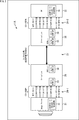
- FIG. 1 is a block diagram showing a configuration example of a first embodiment of a communication system to which the present technology is applied.
- the communication system 11 is configured by connecting an image sensor 21 and an application processor 22 via a bus 23.
- the communication system 11 is used for CSI-2 connection inside an existing mobile device such as a so-called smartphone.
- the image sensor 21 includes, for example, a lens, an image sensor (none of which are shown), and an extended mode CSI-2 transmission circuit 31 incorporated therein.
- the image sensor 21 transmits the image data of the image acquired by the imaging device to the application processor 22 by the extended mode compatible CSI-2 transmission circuit 31.
- the application processor 22 is configured by incorporating an extended mode compatible CSI-2 receiving circuit 32 together with an LSI (Large Scale Integration) that performs processing according to various applications executed by a mobile device including the communication system 11.
- the application processor 22 receives the image data transmitted from the image sensor 21 by the extended mode compatible CSI-2 receiving circuit 32, and the LSI can process the image data according to the application. it can.
- the bus 23 is a communication path for transmitting signals according to the CSI-2 standard, and for example, the transmission distance capable of transmitting signals is about 30 cm. Further, the bus 23 connects the image sensor 21 and the application processor 22 by a plurality of signal lines (I2C, CLKP/N, D0P/N, D1P/N, D2P/N, D3P/N) as illustrated. ..
- the extended mode compatible CSI-2 transmitting circuit 31 and the extended mode compatible CSI-2 receiving circuit 32 support communication in an extended mode in which the CSI-2 standard is extended, and perform mutual signal transmission and reception. You can Detailed configurations of the extended mode compatible CSI-2 transmission circuit 31 and the extended mode compatible CSI-2 reception circuit 32 will be described later with reference to FIGS. 9 and 10.
- FIG. 2 is a block diagram showing a configuration example of a second embodiment of a communication system to which the present technology is applied.
- the image sensor 21 and the serializer 25 are connected via a bus 24-1, and the application processor 22 and the deserializer 26 are connected via a bus 24-2.
- a serializer 25 and a deserializer 26 are connected and configured via a bus 27.
- the communication system 11A is used for connection in an existing vehicle-mounted camera.
- the image sensor 21 and the application processor 22 are configured similarly to the image sensor 21 and the application processor 22 in FIG. 1, and detailed description thereof will be omitted.
- the buses 24-1 and 24-2 are communication paths for transmitting signals in conformity with the CSI-2 standard, and as shown in the drawing, a plurality of signal lines (HS-GPIO , I2C, CLKP/N, D0P/N, D1P/N, D2P/N, D3P/N).
- the serializer 25 includes a CSI-2 receiving circuit 33 and a SerDes (Serializer Deserializer) transmitting circuit 34.
- the CSI-2 receiving circuit 33 communicates with the extended mode-compatible CSI-2 transmitting circuit 31 in accordance with the normal CSI-2 standard, so that the image sensor 21 is transmitted. The signal of the bit parallel which comes is acquired. Then, the serializer 25 converts the acquired signal into bit serial, and the SerDes transmission circuit 34 communicates with the SerDes reception circuit 35 in one lane to transmit the signal to the deserializer 26.
- the deserializer 26 includes a SerDes reception circuit 35 and a CSI-2 transmission circuit 36.
- the deserializer 26 acquires a bit serial signal transmitted by the SerDes reception circuit 35 performing communication in one lane with the SerDes transmission circuit 34. Then, the deserializer 26 converts the acquired signal into bit parallel, and the CSI-2 transmission circuit 36 communicates with the extended mode compatible CSI-2 reception circuit 32 in accordance with the normal CSI-2 standard. Is transmitted to the application processor 22.
- the bus 27 is a communication path that transmits signals in conformity with SerDes standards other than CSI-2, such as FPD (Flat Panel Display)-LINK III.
- SerDes standards other than CSI-2 such as FPD (Flat Panel Display)-LINK III.
- a transmission distance that enables signals to be transmitted. Is about 15 m.
- the extended mode compatible CSI-2 transmitting circuit 31 and the extended mode compatible CSI-2 receiving circuit 32 transmit/receive data in packets having an expanded packet structure as described later. be able to. This makes it possible to support more diverse applications such as RAW24, SmartROI (Region of Interest), and GLD (Graceful Link Degradation) described below.
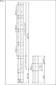
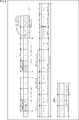
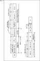
- FIG. 3 shows the overall packet structure of a packet used in the extension mode of CSI-2 when the physical layer is D-PHY (hereinafter, referred to as extension packet for D-PHY).
- the extended packet for D-PHY has the same packet structure as the existing CSI-2 standard in the packet header and packet footer.
- the packet header stores VC (VirtualChannel) indicating the number of virtual channel lines, data type (DataType) indicating the type of data, WC (Word Count) indicating the data length of the payload, and VCX/ECC.
- VC VirtualChannel
- DataType data type
- WC Wide Count
- VCX/ECC Cyclic Redundancy Check
- 0x38-0x3F is defined as the reserved data type transmitted in the packet header. Therefore, in the extension packet for D-PHY, the setting information for identifying the extension mode on the receiving side is newly defined by using the data type that is already reserved.
- DataType[5:3] is defined as extended mode setting information
- DataType[1:0] is extended type. It is defined as setting information.
- the extension mode setting information indicates whether or not the extension mode is set. For example, when DataType[5:3] is 3'b111, it indicates that the extension mode is set. Further, when four types of extended mode 0, extended mode 1, extended mode 2 and extended mode 3 are prepared as types of extended mode, the extended type setting information is any one of them. Indicates For example, when DataType[1:0] is 2'b00, it indicates that the type of extended mode is extended mode 0.
- Extended payload header is placed at the beginning corresponding to the existing CSI-2 standard payload, and must be transmitted in extended mode.
- the extended payload header is configured with setting information such as an SROI identification flag, an extended VC (Virtual Channel), an extended DataType, an OePH selection flag, and an OePF selection flag, as shown in the figure.
- the extended VC expands the VC that was 4 bits in the existing CSI-2 standard to 8 bits
- the expanded DataType expands the DataType that was 4 bits in the existing CSI-2 standard to 8 bits. It
- the optional extended payload header and optional extended payload footer are selectively transmitted according to the purpose.
- the legacy payload corresponds to the same payload as the existing CSI-2 standard.
- the extended payload header, optional extended payload header, and optional extended payload footer shall be 26-bit + 6-bit ECC (Error Correction Code). This makes it possible to divert the existing payload header circuit to suppress an increase in circuit size and improve error resistance.
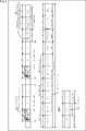
- FIG. 4 shows a short packet (hereinafter, referred to as D-PHY) used in the extension mode of CSI-2 when the physical layer is D-PHY. Packet structure) is shown.
- FIG. 5 shows a packet structure of a long packet (hereinafter referred to as an extended long packet for D-PHY) used in the extended mode of CSI-2 when the physical layer is D-PHY. There is.
- Short Packet Data Field is transmitted. This Short Packet Data Field is the same as that defined in the existing CSI-2 standard.
- MC GLD MessageCount
- RSID vehicle row number and SourceID
- An extended short packet having a packet structure as shown in FIG. 4 can extend the data type and the bit width of the virtual channel as compared with the extended short packet according to the existing CSI-2 standard. It can support various uses defined in the extended payload header. If these functions are not required, the extended short packet according to the existing CSI-2 standard may be transmitted together with the extended long packet.
- the optional extension payload header, legacy payload, and optional extension payload footer are stored in the existing CSI-2 standard payload and transmitted.
- the existing SerDes transmission circuit 34 and the SerDes reception circuit 35 (FIG. 2) recognize the same as the image data transmitted in the existing payload, and as it is. It is transmitted to the latter stage.
- the application processor 22 at the final stage can determine the extended mode by the data type DT[5:0] of the packet header. Therefore, the application processor 22 can interpret the contents of the payload in order from the extended payload header and take out the data in the desired extended mode.
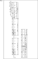
- FIG. 6 shows an overall packet structure of a packet used in the extension mode of CSI-2 when the physical layer is C-PHY (hereinafter, referred to as extension packet for C-PHY).
- extension packet for C-PHY shown in FIG. 6, description of the configuration common to the extension packet for D-PHY of FIG. 3 will be omitted, and a different configuration will be described.
- the extension mode is identified by the data type, and all the data according to each application executed by the application processor 22 is It is embedded in the payload and transmitted.
- the extension packet for C-PHY transmits the packet header twice like the packet for C-PHY conforming to the existing CSI-2 standard, and C-PHY transmits 7 bits of 16bit to 16symbol. Data is arranged in 16-bit units for the convenience of conversion to.
- the extended payload header is placed at the beginning of the payload, but regarding the virtual channel, in the case of C-PHY, the beginning of the existing packet header was reserved for that purpose, so the extended payload header contains the virtual channel. Is not stored.
- the virtual channel may be stored in the extension payload header.
- a flag called OePHF is prepared. If this flag is 1, OePH/OePF information will be transmitted next. Then, after the ePH information and the OePH information, the CRC is transmitted as the extended payload header, and the packet header having the same configuration is transmitted twice. In this way, by making the structure and the structure of the existing packet header transmitted twice, it is possible to achieve both circuit reusability and error resistance.
- FIG. 7 shows a short packet (hereinafter referred to as C-PHY) used in the extension mode of CSI-2 when the physical layer is C-PHY. Packet structure) is shown.
- FIG. 8 shows a packet structure of a long packet (hereinafter referred to as an extended long packet for C-PHY) used in the extended mode of CSI-2 when the physical layer is C-PHY. There is.
- the extended short packet for C-PHY shown in FIG. 7 does not have a large difference in packet structure from the extended short packet for D-PHY shown in FIG. 4, and the extended long packet for C-PHY shown in FIG. Does not differ greatly from the extended long packet for D-PHY shown in FIG. 5 and the packet structure.
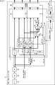
- FIG. 9 is a block diagram showing a configuration example of the image sensor 21 including the extended mode compatible CSI-2 transmission circuit 31.
- the image sensor 21 includes a pixel 41, an AD converter 42, an image processing unit 43, a pixel CRC calculation unit 44, a physical layer processing unit 45, in addition to the extended mode compatible CSI-2 transmission circuit 31. It is configured to include an I2C/I3C slave 46 and a register 47.
- the extended mode compatible CSI-2 transmission circuit 31 includes a packing unit 51, a packet header generation unit 52, a payload header generation unit 53, a payload footer generation unit 54, selection units 55 and 56, a CRC calculation unit 57, and a lane distribution unit 58. , CCI slave 59, and controller 60.
- the pixel 41 outputs an analog pixel signal according to the amount of received light
- an AD converter ADC: Analog-to-Digital Converter
- ADC Analog-to-Digital Converter
- An image processing unit (ISP: Image Signal Processor) 43 supplies image data obtained by performing various types of image processing on an image based on a pixel signal to the pixel CRC calculation unit 44 and the packing unit 51. Further, the image processing unit 43 supplies the data enable signal data_en indicating whether the image data is valid to the packing unit 51 and the controller 60.
- the pixel CRC calculation unit 44 calculates and calculates a CRC for each pixel in the image data supplied from the image processing unit 43, and supplies the CRC to the payload footer generation unit 54.
- the physical layer processing unit 45 can execute physical layer processing of both C-PHY and D-PHY. For example, the physical layer processing unit 45 executes the physical layer processing of the C-PHY when the C layer enable signal cphy_en supplied from the controller 60 is valid, and when the C layer enable signal cphy_en is invalid. Executes physical layer processing of D-PHY. Then, the physical layer processing unit 45 transmits the packet divided into four lanes by the lane distribution unit 58 to the application processor 22.
- the I2C/I3C slave 46 communicates according to the I2C/I3C master 72 (FIG. 10) of the application processor 22 based on the I2C (Inter-Integrated Circuit) or I3C (Improved Inter Integrated Circuits) standard.
- settings transmitted from the application processor 22 are written in the register 47 via the I2C/I3C slave 46 and the CCI slave 59.
- the settings written in the register 47 for example, communication settings according to the CSI-2 standard, extended mode settings indicating whether or not the extended mode is used, and fixed communication settings required for communication in the extended mode. and so on.
- the packing unit 51 performs a packing process of storing the image data supplied from the image processing unit 43 in the payload of the packet, and supplies the payload to the selection unit 55 and the lane distribution unit 58.
- the packet header generation unit 52 when instructed to generate the packet header according to the packet header generation instruction signal ph_go supplied from the controller 60, generates the packet header and supplies it to the selection unit 55 and the lane distribution unit 58.
- the packet header generation unit 52 generates, according to the existing CSI-2 standard, a packet header storing setting information indicating a condition set for data transmitted in a packet, for example, a data type indicating a data type. .. Also, the packet header generation unit 52 uses the extension header in an unused area defined as unused in the existing CSI-2 standard in the data type that is the setting information indicating the type of data transmitted in the packet. The extension mode setting information indicating whether or not the extension mode setting is performed is stored. Further, the packet header generation unit 52 stores, in the unused area, extension type setting information indicating which type of extension modes of a plurality of types prepared as extension modes.
- the payload header generation unit 53 generates each of the extension payload header and the optional extension payload header according to the extension payload header generation instruction signal eph_go and the extension payload header enable signal ePH_en supplied from the controller 60, and the selection unit 56 and the lane distribution unit 58. Supply to.
- the payload header generation unit 53 is supplied with an in-vehicle row number, a source ID (identification), etc. according to the application of the image sensor 21, and converts them into an extended payload header or an optional extended payload header as necessary. Store.
- the payload header generating unit 53 generates an extended payload header storing the setting information as shown in FIG. 3, for example, separately from the packet header generated by the packet header generating unit 52. Further, when transmitting the optional extension header, the payload header generation unit 53 should transmit the optional extension header as optional extension header setting information (OePH[7:0]) indicating whether or not to transmit the optional extension header.
- the optional extension header setting information indicating is stored in the extension header, and the optional extension header is generated following the extension header.
- the payload footer generation unit 54 generates an optional extended payload footer according to the extended payload footer generation instruction signal epf_go and the extended payload header enable signal ePF_en supplied from the controller 60, and supplies the optional extended payload footer to the selection unit 56 and the lane distribution unit 58.
- the payload footer generation unit 54 uses the legacy payload in which the data is stored. Generate an optional extension footer that is placed consecutively.
- the controller 60 also supplies a C layer enable signal cphy_en to the packet header generation unit 52, the payload header generation unit 53, and the payload footer generation unit 54.
- the C layer enable signal cphy_en indicates that the packet header is valid
- the packet header generation unit 52 generates a packet header for C-PHY
- the payload header generation unit 53 causes the extended payload header and optional extended payload for C-PHY.
- the header is generated, and the payload footer generator 54 generates an optional extended payload footer for C-PHY.
- the C layer enable signal cphy_en indicates invalid, the packet header generation unit 52 generates the D-PHY packet header, and the payload header generation unit 53 the D-PHY extended payload header and the optional extended payload.
- the header is generated, and the payload footer generation unit 54 generates an optional extended payload footer for D-PHY.
- the selecting unit 55 selects the packet header supplied from the packet header generating unit 52 according to the C layer enable signal cphy_en supplied from the controller 60, and supplies the packet header to the selecting unit 56. ..
- the selection unit 55 selects the payload supplied from the packing unit 51 and supplies it to the selection unit 56.
- the selection unit 56 selectively supplies the packet header or payload via the selection unit 55, the extended payload header and the optional extended payload supplied from the payload header generation unit 53.
- One of the optional extended payload footer supplied from the header and payload footer generation unit 54 is selected and supplied to the CRC calculation unit 57.
- the CRC calculation unit 57 calculates and calculates the CRC of the packet header, the payload, the extension payload header, the optional extension payload header, or the optional extension payload footer selectively supplied through the selecting unit 56, and the CRC is lane-distributed. It is supplied to the part 58.
- the lane distribution unit 58 receives the payload supplied from the packing unit 51, the packet header supplied from the packet header generation unit 52, the extended payload header supplied from the payload header generation unit 53, and the optional extended payload header.
- the optional extended payload footer supplied from the payload footer generation unit 54 and the CRC supplied from the CRC calculation unit 57 are distributed to four lanes according to the CSI-2 standard and supplied to the physical layer processing unit 45. To do.
- the CCI (Camera Control Interface) slave 59 communicates according to the CSI-2 standard, under the initiative of the CCI master 88 (FIG. 10) of the application processor 22.
- the controller 60 reads out various settings stored in the register 47, and controls each block constituting the extended mode compatible CSI-2 transmission circuit 31 according to these settings. For example, the controller 60 controls switching between transmission of a packet having a packet structure conforming to the existing CSI-2 standard and transmission of a packet having a packet structure in the extended mode, depending on the content of data to be transmitted.
- the image sensor 21 is configured as described above, and it is possible to generate an extended packet having a packet structure as described with reference to FIGS. 3 to 8 and send it to the application processor 22.
- FIG. 10 is a block diagram showing a configuration example of the application processor 22 including the CSI-2 receiving circuit 32 supporting the extended mode.
- the application processor 22 includes a physical layer processing unit 71, an I2C/I3C master 72, a register 73, and a controller 74, in addition to the extended mode compatible CSI-2 receiving circuit 32.
- the extended mode compatible CSI-2 receiving circuit 32 includes a packet header detecting unit 81, a lane merging unit 82, an interpreting unit 83, selecting units 84 and 85, a CRC calculating unit 86, an unpacking unit 87, and a CCI master 88. Prepared for.
- the physical layer processing unit 71 can execute both physical layer processing of C-PHY and D-PHY. As described above, the physical layer processing unit 45 of the image sensor 21 performs one of the C-PHY and the D-PHY physical layer processing, and the physical layer processing unit 71 causes the physical layer processing unit 45 to perform the physical layer processing. Perform the same physical layer processing that was performed in.
- the I2C/I3C master 72 takes the initiative in communication with the I2C/I3C slave 46 (FIG. 9) of the image sensor 21 based on the I2C or I3C standard.
- the controller 74 records various settings to be written in the register 47 of the image sensor 21 in the register 73.
- the controller 74 controls each block forming the application processor 22.
- mrg_en merging enable signal
- the packet header detection unit 81 detects the packet header in which the setting information (data type etc.) indicating the condition set for the data transmitted in the packet is stored according to the existing CSI-2 standard. At this time, the packet header detection unit 81 is stored in an unused area defined as unused in the existing CSI-2 standard in the data type that is the setting information indicating the type of data transmitted in the packet. , The extended mode detection flag is output according to the extended mode setting information indicating whether or not the extended mode uses the extended header to receive the packet having the packet structure according to the existing CSI-2 standard and the extended mode. Switch to reception of a packet having a packet structure at time.
- the packet header detection unit 81 has a plurality of types of extension modes prepared as extension modes according to extension mode type information stored in an unused area of a data type defined as unused in the existing CSI-2 standard. Recognize which type of extended mode is selected.
- the lane merging unit 82 merges the packets divided into four lanes supplied from the physical layer processing unit 71 when the merging enable signal mrg_en supplied from the packet header detection unit 81 is valid. Then, the lane merging unit 82 supplies the packet of one lane to the interpretation unit 83, the selection unit 84, and the selection unit 85.
- the interpretation unit 83 determines from the packet supplied from the lane merging unit 82 based on the packet structure of the extension mode. , Extended payload header, optional extended payload header, and optional extended payload footer. Then, the interpretation unit 83 interprets the setting information stored in the extension payload header, the optional extension payload header, and the optional extension payload footer.
- the interpretation unit 83 receives, as an extension header, an extension payload header placed at the beginning of the payload according to the existing CSI-2 standard, and interprets the setting information stored in the extension payload header. Further, when the optional extension header setting information stored in the extension header indicates that the optional extension header transmitted selectively according to the use is transmitted, the interpretation unit 83 follows the extension header and the optional extension header. Receives the extension header and interprets the setting information stored in the optional extension header. Furthermore, when the packet transmitted in the extended mode is an extended long packet that stores data transmitted as a payload in the existing CSI-2 standard, the interpreting unit 83 follows the legacy payload in which the data is stored. Receives the optional extension footer to be placed and interprets the optional extension footer.
- the interpretation unit 83 reads, for example, the vehicle-mounted line number and the source ID stored in the optional extension payload header and outputs them to the LSI (not shown) in the subsequent stage.
- the interpreting unit 83 determines that the extended mode detection flag supplied from the packet header detection unit 81 does not indicate the extended mode, that is, if the packet having the existing packet structure is supplied. Stops without performing the processing described above.
- the selection unit 84 selectively supplies data to the unpacking unit 87 according to the extension mode detection flag supplied from the packet header detection unit 81, based on the packet structure of the existing packet or the packet structure of the expansion packet.
- the selection unit 85 selectively supplies data to the CRC calculation unit 86 based on the packet structure of the existing packet or the packet structure of the extended packet according to the extension mode detection flag supplied from the packet header detection unit 81.
- the CRC calculation unit 86 calculates the CRC of the packet header, payload, extended payload header, optional extended payload header, or optional extended payload footer that is selectively supplied via the selection unit 85. Then, when a CRC error is detected, the CRC calculator 86 outputs a crc error detection signal indicating that to a subsequent LSI (not shown).
- the unpacking unit 87 performs an unpacking process for extracting the image data stored in the payload selectively supplied via the selection unit 84, and outputs the acquired image data to a subsequent stage LSI (not shown). ..
- the CCI master 88 takes the initiative in communication with the CCI slave 59 (FIG. 9) of the image sensor 21 based on the CSI-2 standard.
- the application processor 22 is configured as described above, receives the extension packet transmitted from the image sensor 21, and interprets the setting information stored in the extension payload header, the optional extension payload header, and the optional extension payload footer. Then, the image data can be obtained.
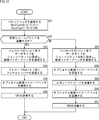
- FIG. 11 is a flowchart illustrating a process in which the image sensor 21 transmits a packet.
- step S11 the controller 60 determines whether to use the extended mode when starting communication with the application processor 22. For example, the controller 60 confirms the extended mode setting stored in the register 47, and determines that the extended mode is used when the extended mode setting indicating that the extended mode is used is written by the application processor 22.
- step S11 determines in step S11 that the extended mode is not used. If the controller 60 determines in step S11 that the extended mode is not used, the process proceeds to step S12.
- step S12 the I2C/I3C slave 46 receives the transmission start command of the image data transmitted from the application processor 22 (in step S54 of FIG. 13 described later). Further, the I2C/I3C slave 46 receives the communication setting according to the CSI-2 standard transmitted together with the transmission start command, and writes it in the register 47 via the CCI slave 59.
- step S13 the image sensor 21 executes the conventional packet transmission process of transmitting the packet having the packet structure according to the existing CSI-2 standard to the application processor 22 based on the communication setting stored in the register 47. To be done.
- step S11 when the controller 60 determines to use the extended mode, the process proceeds to step S14.
- step S14 the I2C/I3C slave 46 receives the fixed communication settings (for example, PH/PF copy for each lane in GLD) required for communication in the extended mode, and the I2C/I3C slave 46 receives the fixed communication settings via the CCI slave 59. Write to register 47.
- the fixed communication settings for example, PH/PF copy for each lane in GLD
- step S15 the I2C/I3C slave 46 receives the transmission start command of the image data transmitted from the application processor 22 (in step S57 of FIG. 13 described later). Further, the I2C/I3C slave 46 receives the communication setting according to the CSI-2 standard transmitted together with the transmission start command, and writes it in the register 47 via the CCI slave 59.
- step S16 the controller 60 determines whether or not to start packet transmission, and waits for processing until it is determined to start packet transmission.
- step S16 when it is determined that the packet transmission is started, the process proceeds to step S17, and the controller 60 determines whether or not the data should be transmitted in the extended mode.
- the controller 60 determines that the data should be transmitted in the extended mode, for example, if the data is transmitted in a use case of an application example described later. To do.
- step S17 When the controller 60 determines in step S17 that the data is to be transmitted in the extended mode, the process proceeds to step S18, and the extended mode transmission process (see FIG. 12) for transmitting the extended packet corresponding to the extended mode is performed. Be seen.
- step S17 determines in step S17 that the data is not data to be transmitted in the extended mode.
- step S19 the controller 60 determines whether to send a short packet. For example, the controller 60 determines to transmit the short packet at the start of the frame and at the end of the frame.
- step S19 If it is determined in step S19 that the controller 60 transmits a short packet, the process proceeds to step S20.
- step S20 the packet header generation unit 52 generates a packet header and transmits the short packet having the conventional packet structure to the application processor 22.
- step S19 when the controller 60 determines that the short packet is not transmitted (that is, the long packet is transmitted), the process proceeds to step S21.
- step S21 the packing unit 51 stores the image data in the payload, and the CRC calculation unit 57 obtains the CRC to generate a long packet having a conventional packet structure, and transmits the long packet to the application processor 22.
- step S18 After the processing of step S18, step S20, or step S21, the processing proceeds to step S22, and the controller 60 ends the packet transmission processing. After that, the process returns to step S16, and the process of transmitting the packet is repeated for the next packet.
- FIG. 12 is a flowchart illustrating the extended mode transmission process performed in the process of step S18 of FIG.
- step S31 the packet header generation unit 52 generates a packet header storing VC, data type, WC, etc., and sends it to the application processor 22.
- DataType[1:0] 2'b00
- step S32 the application processor 22 determines whether to send the extended short packet. For example, the controller 60 determines to transmit the extended short packet at the start of the frame and at the end of the frame.
- step S32 If the application processor 22 determines to transmit the extended short packet in step S32, the process proceeds to step S33.
- step S33 the payload header generation unit 53 transmits the extended payload header in which the data type (DataType[7:0]) is set to short packet in the first byte of the payload.
- the payload header generation unit 53 performs various settings stored in the extended payload header (for example, OePH[7:0] and OePF[3:0]).
- step S34 the payload header generation unit 53 stores the frame number (FN: FrameNumber) in the second byte of the payload and transmits it.
- FN FrameNumber
- step S35 the payload header generation unit 53 generates and transmits the optional extension payload header as shown in FIG. 4 according to the setting (OePH[7:0]) performed in step S33.
- step S36 the CRC calculation unit 57 obtains the CRC and transmits it as a packet footer.
- step S32 determines in step S32 that the extended short packet is not transmitted (that is, the long packet is transmitted). the process proceeds to step S37.
- step S37 the payload header generation unit 53 transmits the extended payload header in which the data type (DataType[7:0]) is set to other than short packet in the first byte of the payload.
- the payload header generation unit 53 performs various settings stored in the extended payload header (for example, OePH[7:0] and OePF[3:0]).
- step S38 the payload header generation unit 53 generates and transmits the optional extension payload header as shown in FIG. 5 according to the setting (OePH[7:0]) performed in step S37.
- step S39 the packing unit 51 packs the image data supplied from the image processing unit 43, generates a legacy payload, and transmits it.
- step S40 the payload footer generation unit 54 generates and transmits the optional extended payload footer as shown in FIG. 4 according to the setting (OePF[3:0]) performed in step S37.
- step S41 the CRC calculation unit 57 obtains the CRC and transmits it as a packet footer.
- step S36 or S41 the extended mode transmission processing is ended.
- the image sensor 21 can generate and transmit an extended short packet or an extended long packet.
- FIG. 13 is a flowchart for explaining the process in which the application processor 22 receives a packet.
- step S 51 the process is started when the image sensor 21 is connected to the application processor 22 via the bus 23.
- the controller 74 writes the initial settings of the image sensor 21 (for example, which one of C-PHY and D-PHY is used as the physical layer) in the register 73, and the I 2 C/I 3 C via the CCI master 88. It is transmitted to the image sensor 21 by the master 72. As a result, the initial setting is written in the register 47 of the image sensor 21.
- step S52 the controller 74 recognizes whether the image sensor 21 supports the extended mode. For example, the controller 74 obtains the setting value (for example, extended PH/PF compatible capability) stored in the register 47 of the image sensor 21 by the I2C/I3C master 72, so that the image sensor 21 corresponds to the extended mode. It can be recognized whether or not. Alternatively, the controller 74 can recognize in advance whether or not the image sensor 21 is compatible with the extension mode based on, for example, an input by a manual or the like.
- the setting value for example, extended PH/PF compatible capability
- step S53 the controller 74 determines whether the image sensor 21 supports the extended mode and the application executed by the application processor 22 requires use of the extended mode.
- step S53 when the controller 74 determines that the image sensor 21 does not support the extended mode or the use of the extended mode is not required, the process proceeds to step S54.
- step S54 the controller 74 transmits an image data transmission start command to the image sensor 21 by the I2C/I3C master 72. At this time, the controller 74 also transmits the communication settings according to the CSI-2 standard.
- step S55 the application processor 22 performs the conventional packet reception process of receiving the packet having the packet structure according to the existing CSI-2 standard, based on the communication setting transmitted in step S54.
- step S53 determines in step S53 that the image sensor 21 is compatible with the extended mode and that the application executed by the application processor 22 requires the use of the extended mode, the process proceeds to step S56. Proceed to.
- step S56 the I2C/I3C master 72 transmits the fixed communication setting required for communication in the extended mode before the communication in the extended mode is started. As a result, the fixed communication settings are written in the register 47 of the image sensor 21 (step S14 in FIG. 11).
- step S57 the controller 74 causes the I2C/I3C master 72 to transmit an image data transmission start command to the image sensor 21. At this time, the controller 74 also transmits the communication settings according to the CSI-2 standard.
- step S58 the packet header detection unit 81 determines whether or not the packet reception is started by confirming the data supplied from the physical layer processing unit 71, and the process is performed until it is determined that the packet reception is started. To wait.
- the packet header detection unit 81 when detecting the packet header from the data supplied from the physical layer processing unit 71, determines that the reception of the packet has started.
- step S58 If the packet header detection unit 81 determines in step S58 that reception of the packet has started, the process proceeds to step S59.
- step S59 When the packet header detection unit 81 determines in step S59 that the packet that has started to be received is an extension packet, the process proceeds to step S60, and an extension mode reception process (see FIG. 14) for receiving the extension packet is performed. ..
- step S59 when the packet header detection unit 81 determines that the packet that has started reception is not the extension packet, the process proceeds to step S61.
- step S61 the packet header detection unit 81 confirms the data type (DataType[5:0]) of the packet header detected in step S58, and determines whether or not the packet whose reception has started is a short packet. ..
- step S61 if the packet header detection unit 81 determines that the packet that has started receiving is a short packet, the process proceeds to step S62.
- step S62 the packet header detection unit 81 receives the short packet having the conventional packet structure transmitted from the image sensor 21.
- step S61 when the packet header detection unit 81 determines that the packet that has started reception is not a short packet (that is, reception of long packet has started), the process proceeds to step S63.
- the unpacking unit 87 receives the payload of the long packet of the conventional packet structure transmitted from the image sensor 21 and extracts the image data, and the CRC calculation unit 86 transmits the packet header after the payload. WC + 1st byte is received as CRC.
- step S60 After the processing of step S60, step S62, or step S63, the processing proceeds to step S64, and the controller 74 ends the packet reception processing. After that, the process returns to step S58, and the process of receiving the packet is repeated for the next packet.
- FIG. 14 is a flowchart illustrating the extended mode reception process performed in the process of step S60 of FIG.
- step S71 if the packet header detection unit 81 determines that the mode setting of the extended mode is extended mode 0, the process proceeds to step S72.
- step S72 the interpretation unit 83 receives the first byte of the payload as an extended payload header.
- step S73 the interpretation unit 83 confirms the data type (DataType[7:0]) of the extended payload header received in step S72, and determines whether or not the packet whose reception has started is an extended short packet. ..
- step S73 when the interpretation unit 83 determines that the packet is an extended short packet, the process proceeds to step S74.
- the interpretation unit 83 receives the optional extension payload header according to the setting (OePH[7:0]) stored in the extension payload header received in step S72.
- step S75 the CRC calculation unit 86 receives the WC+1st byte transmitted after the optional extension payload header as the CRC.
- step S73 when the interpretation unit 83 determines that it is not the extended short packet (that is, the reception of the extended long packet is started), the process proceeds to step S76.
- step S76 the interpretation unit 83 receives the optional extension payload header according to the setting (OePH[7:0]) stored in the extension payload header received in step S72.
- step S77 the unpacking unit 87 receives the legacy payload of the extended long packet transmitted from the image sensor 21 and extracts the image data.
- step S78 the interpretation unit 83 receives the optional extended payload footer according to the setting (OePF[3:0]) stored in the extended payload header received in step S72.
- step S79 the CRC calculation unit 86 receives, as a CRC, the WC+1st byte transmitted following the optional extension payload footer.
- step S71 when it is determined in step S71 that the mode setting of the extended mode is not the extended mode 0, the extended mode reception process is ended after the process of step S75 or the process of step S79.
- the application processor 22 can receive the extended short packet or the extended long packet and acquire the data.
- the packet header and the packet footer are the same as those of the existing CSI-2 standard, with an emphasis on maintaining compatibility with the existing CSI-2 standard.
- a packet structure is used, and the packet structure is expanded by an extended payload header, an optional extended payload header, and an optional extended payload footer.
- the packet header and the packet footer are different from the existing CSI-2 standard, and the packet structure is expanded by the extended packet header and the extended packet footer.
- FIG. 15 shows a packet structure of a short packet (hereinafter, an extended short packet for D-PHY) used in the CSI-2 extended mode when the physical layer is D-PHY.
- a short packet hereinafter, an extended short packet for D-PHY
- the extended short packet for D-PHY shown in FIG. 15 is stored in the same packet header as the existing CSI-2 standard, like the extended short packet for D-PHY of the first structural example shown in FIG.
- the extended data type identifies the extended mode.
- the frame number is set in the short packet data field as in the short packet according to the existing CSI-2 standard. Is stored. Then, following the packet header, an extended packet header configured similar to the extended payload header shown in FIG. 4 is transmitted.
- the application processor 22 on the receiving side interprets the data type stored in the extended packet header and determines that the frame number is stored in the data field of the packet header in the case of the extended short packet. can do.
- the optional extension packet header in the extended short packet for D-PHY shown in FIG. 15 is configured similarly to the optional extended payload header in the extended short packet for D-PHY of the first structural example shown in FIG. It However, since the optional extension packet header has a packet structure that is not embedded in the payload, it is not necessary to add a CRC at the end.
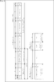
- FIG. 16 shows a packet structure of a long packet (hereinafter, an extended long packet for D-PHY) used in the CSI-2 extended mode when the physical layer is D-PHY.
- a long packet hereinafter, an extended long packet for D-PHY
- the extended data is not embedded in the payload but is transmitted as a part of the packet header or the packet footer. Therefore, the WC of the head packet header indicates the byte length of the payload as in the existing standard.
- FIG. 17 shows a packet structure of a short packet (hereinafter, an extended short packet for C-PHY) used in the extended mode of CSI-2 when the physical layer is C-PHY.
- a short packet hereinafter, an extended short packet for C-PHY
- the extended portion of the extended short packet for C-PHY shown in FIG. 17 is transmitted as an extension of the packet header according to the existing CSI-2 standard, so an extended portion such as an extended payload header is inserted after the frame number. It Then, like the existing CSI-2 standard, the packet header ends with CRC. Further, the packet structure for transmitting these twice with SYNC in between is similar to the short packet conforming to the existing CSI-2 standard.
- FIG. 18 shows a packet structure of a long packet (hereinafter, an extended long packet for C-PHY) used in CSI-2 extended mode when the physical layer is C-PHY.
- a long packet hereinafter, an extended long packet for C-PHY
- the extended long packet for C-PHY shown in FIG. 18 is the first packet shown in FIG. 8 in that the WC of the head packet header indicates the byte length of the payload as in the existing standard. There is a difference from the extended long packet for C-PHY in the structural example.
- the packet structure of the extended packet of the second structure example shown in FIGS. 15 to 18 is more diverse than the conventional one, similarly to the packet structure of the extended packet of the first structure example (FIGS. 3 to 8). It is possible to meet various uses.
- the extension packet of the second structure example has a packet structure in which the existing packet header and footer are extended without embedding the extension data in the existing payload. Therefore, when the packet structure of the extended packet of the second structural example is adopted, compared with the case of adopting the packet structure of the extended packet of the first structural example, the communication system which has been conventionally used is The impact that would require changes cannot be minimized. That is, for example, the existing SerDes transmission circuit 34 needs to be changed from the SerDes reception circuit 35 (FIG. 2).
- an in-vehicle system can be constructed with a minimal effect.
- Each block constituting the image sensor 21 of FIG. 9 and the application processor 22 of FIG. 10 described above was configured so as to be able to perform processing corresponding to both D-PHY and C-PHY packets.
- both a block for exclusively processing a D-PHY packet and a block for exclusively processing a C-PHY packet may be provided, and the respective processes may be switched. ..
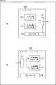
- the image sensor 21A shown in A of FIG. 19 includes a D layer processing block unit 101, a C layer processing block unit 102, a switching unit 103, and a controller 60.
- the D layer processing block unit 101 has a block that exclusively processes a packet for D-PHY among the blocks configuring the image sensor 21 in FIG. 9.
- the C-layer processing block unit 102 includes a block that exclusively processes a packet for C-PHY among the blocks that configure the image sensor 21 in FIG. 9.
- the switching unit 103 outputs the D-PHY packet generated in the D-layer processing block unit 101 according to the control of the controller 60 and the C-PHY for the physical layer. When used, switching is performed so as to output a C-PHY packet generated in the C layer processing block unit 102.
- the application processor 22A shown in B of FIG. 19 includes a switching unit 111, a D layer processing block unit 112, a C layer processing block unit 113, and a controller 74.
- the switching unit 111 switches so that the packet transmitted from the image sensor 21A is supplied to one of the D layer processing block unit 112 and the C layer processing block unit 113.
- the D-layer processing block unit 112 has a block that exclusively processes a packet for D-PHY among the blocks that configure the application processor 22 in FIG. 10.
- the C-layer processing block unit 113 has a block that exclusively processes a packet for C-PHY among the blocks that configure the application processor 22 in FIG. 10.
- the physical layer to be used can be set between the controller 60 and the controller 74 before starting communication. Then, for example, when the D-PHY is used for the physical layer, the D-PHY packet generated in the D layer processing block unit 101 is transmitted via the switching unit 103, and the D-PHY packet is transmitted via the switching unit 111. The layer processing block unit 112 is supplied and processed. Further, for example, when the C-PHY is used for the physical layer, the C-PHY packet generated in the C layer processing block unit 102 is transmitted via the switching unit 103 and the C-PHY packet is transmitted via the switching unit 111. The layer processing block unit 113 is supplied and processed.
- RAW6, RAW7, RAW8, RAW10, RAW12, RAW14, RAW16, and RAW20 are defined as the data types stored in the packet header according to the existing CSI-2 standard. There is.
- RAW24 the data type of the extension payload header.
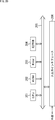
- Extending packets is also considered to be applied to SmartROI, which is a technology that transmits only the image area of interest on the screen.
- extension packet for example, it is possible to transmit coordinate data of 16 bits or more for each of the X coordinate and the Y coordinate.
- GLD is a proposal that is being considered in CSI-2 ver3.0.
- the in-vehicle camera interface has at least a disconnection detection function, and shows the line number (16bit) indicating the line number of information on the screen, the SourceID (8bit) indicating which camera sent the data, and the transmission number. Information such as message counter (16bit) is required. Furthermore, when used in combination with the SROI as described above, it is conceivable that these pieces of information are transmitted in frame units.
- FIG. 20 is a block diagram showing a hardware configuration example of a computer that executes the series of processes described above by a program.
- a CPU Central Processing Unit
- ROM Read Only Memory
- RAM Random Access Memory
- EEPROM Electrically Erasable and Programmable Read Only Memory
- the CPU 201 loads the programs stored in the ROM 202 and the EEPROM 204 into the RAM 203 via the bus 205 and executes the programs to perform the series of processes described above.
- the program executed by the computer can be written in the ROM 202 in advance, or can be externally installed or updated in the EEPROM 204 via the input/output interface 206.
- the processing performed by the computer according to the program does not necessarily have to be performed in time series in the order described as the flowchart. That is, the processing performed by the computer according to the program also includes processing that is executed in parallel or individually (for example, parallel processing or object processing).
- the program may be processed by one computer (processor) or may be processed by a plurality of computers in a distributed manner. Further, the program may be transferred to a remote computer and executed.
- the system means a set of a plurality of constituent elements (devices, modules (parts), etc.), and it does not matter whether or not all constituent elements are in the same housing. Therefore, a plurality of devices housed in separate housings and connected via a network, and one device housing a plurality of modules in one housing are all systems. ..
- the configuration described as one device (or processing unit) may be divided and configured as a plurality of devices (or processing units).
- the configurations described above as a plurality of devices (or processing units) may be integrated into one device (or processing unit).
- part of the configuration of a certain device (or processing unit) may be included in the configuration of another device (or another processing unit). ..
- the present technology can have a configuration of cloud computing in which one device is shared by a plurality of devices via a network and jointly processes.
- the program described above can be executed in any device.
- the device may have a necessary function (function block or the like) so that necessary information can be obtained.
- each step described in the above-mentioned flowchart can be executed by one device or shared by a plurality of devices.
- the plurality of processes included in the one step can be executed by one device or shared by a plurality of devices.
- a plurality of processes included in one step can be executed as a process of a plurality of steps.
- the processes described as a plurality of steps can be collectively executed as one step.
- the program executed by the computer may be configured such that the processes of the steps for writing the program are executed in time series in the order described in this specification, or in parallel, or when the call is made. It may be executed individually at a necessary timing such as time. That is, as long as no contradiction occurs, the processing of each step may be executed in an order different from the order described above. Furthermore, the process of the step of writing this program may be executed in parallel with the process of another program, or may be executed in combination with the process of another program.
- a packet header generation unit that stores setting information indicating conditions set for data transmitted in packets and generates a packet header according to the existing CSI-2 standard
- an extension header generation unit that generates an extension header that stores the setting information is provided
- the packet header generation unit in the data type that is the setting information indicating the type of data transmitted in the packet, in the unused area defined as unused in the existing CSI-2 standard, the extension header,
- a communication device that stores extended mode setting information indicating whether or not the extended mode to be used is used.
- extension header generation unit generates, as the extension header, an extension payload header arranged at the beginning of a payload according to the existing CSI-2 standard.
- extension header generation unit generates, as the extension header, an extension packet header arranged subsequent to the packet header so as to extend the standard of the packet header.
- the extension header generation unit stores, in the extension header, optional extension header setting information indicating whether or not to send an optional extension header selectively transmitted according to a use. (1) to (3) The communication device according to any one of 1.
- the extension header generation unit stores the optional extension header setting information indicating that the optional extension header is transmitted, in the extension header, and after the extension header, the optional extension header.
- the communication device according to any one of (1) to (4) above.
- the packet header generation unit stores, in the unused area, extension type setting information indicating which type of extension modes of a plurality of types prepared as the extension mode is set.
- the communication device according to any one of (5).
- (7) When the packet transmitted in the extended mode is an extended long packet that stores data transmitted as a payload in the existing CSI-2 standard, an optional packet that is arranged subsequent to the legacy payload in which the data is stored
- the communication device according to any one of (1) to (6), further including an optional extension footer generation unit that generates an extension footer.
- a control unit is further provided for controlling switching between transmission of a packet structure packet conforming to the existing CSI-2 standard and transmission of a packet structure packet in the extended mode according to the content of the data to be transmitted.
- the communication device according to any one of 1) to (7).
- the communication device that communicates Storing the setting information indicating the conditions set for the data transmitted in the packet, and generating the packet header according to the existing CSI-2 standard, Aside from the packet header, generating an extension header storing the setting information,
- the data type which is the setting information indicating the type of data transmitted in the packet, is the extension mode in which the extension header is used in an unused area defined as unused in the existing CSI-2 standard?
- a communication method that stores extended mode setting information that indicates whether or not it is present.
- a packet header detection unit that detects the packet header in which the setting information indicating the conditions set for the data transmitted in the packet is stored according to the existing CSI-2 standard, An interpreting unit that interprets the setting information stored in an extension header different from the packet header, The packet header detection unit, in the data type that is the setting information indicating the type of data transmitted in the packet, stored in an unused area defined as unused in the existing CSI-2 standard, According to the extension mode setting information indicating whether or not the extension mode using the extension header, the reception of the packet structure packet according to the existing CSI-2 standard, and the reception of the packet structure packet in the extension mode A communication device that causes switching.
- the interpretation unit receives, as the extension header, an extension payload header placed at the beginning of a payload according to the existing CSI-2 standard, and interprets the setting information stored in the extension payload header ( The communication device according to 11).
- the interpretation unit receives, as the extension header, an extension packet header arranged subsequent to the packet header so as to extend the standard of the packet header, and interprets the setting information stored in the extension header.
- the interpretation unit follows the extension header and then The communication device according to any one of (11) to (13) above, which receives an optional extension header and interprets the setting information stored in the optional extension header.
- the packet header detection unit recognizes which type of extension mode is selected from the plurality of types of extension modes prepared as the extension mode according to the extension mode type information stored in the unused area.
- the communication device according to any one of (11) to (14) above.
- the interpretation unit when the packet transmitted in the extended mode is an extended long packet storing data transmitted as a payload in the existing CSI-2 standard, continues the legacy payload in which the data is stored.
- the communication device according to any one of (11) to (15) above, which receives an optional extended footer that is arranged as a unit and interprets the optional extended footer.
- the communication device that communicates Detecting a packet header that stores setting information indicating conditions set for data transmitted in a packet according to the existing CSI-2 standard, Interpreting the setting information stored in an extension header different from the packet header, In the data type that is the setting information indicating the type of data transmitted in the packet, an extension that uses the extension header is stored in an unused area that is defined as unused in the existing CSI-2 standard.
- a communication method that switches between receiving a packet with a packet structure conforming to the existing CSI-2 standard and receiving a packet with a packet structure in the extended mode according to the extended mode setting information that indicates whether or not the mode is set.
Landscapes
- Engineering & Computer Science (AREA)
- Theoretical Computer Science (AREA)
- Computer Security & Cryptography (AREA)
- Computer Networks & Wireless Communication (AREA)
- Signal Processing (AREA)
- Physics & Mathematics (AREA)
- General Engineering & Computer Science (AREA)
- General Physics & Mathematics (AREA)
- Communication Control (AREA)
- Data Exchanges In Wide-Area Networks (AREA)
- Information Transfer Systems (AREA)
- Mobile Radio Communication Systems (AREA)
Abstract
Description
図1は、本技術を適用した通信システムの第1の実施の形態の構成例を示すブロック図である。
図3乃至図8を参照して、拡張モード対応CSI-2送信回路31および拡張モード対応CSI-2受信回路32の間の通信で用いられるパケットのパケット構造の第1の構造例について説明する。
・DataType[5:3]=3’b111の場合、拡張モード
・DataType[2]=Reserve(RES:将来の拡張のための予約)
・DataType[1:0]=extension mode type(4つの拡張モードを用意)
を定義する。
図9は、拡張モード対応CSI-2送信回路31を備えるイメージセンサ21の構成例を示すブロック図である。
図11乃至図14を参照して、イメージセンサ21およびアプリケーションプロセッサ22で行われる通信処理について説明する。
図15乃至図18を参照して、拡張モード対応CSI-2送信回路31および拡張モード対応CSI-2受信回路32の間の通信で用いられるパケットのパケット構造の第2の構造例について説明する。
図19を参照して、イメージセンサおよびアプリケーションプロセッサの変形例について説明する。
上述した拡張パケットは、例えば、以下のようなユースケースに適用することが検討されている。
次に、上述した一連の処理(通信方法)は、ハードウエアにより行うこともできるし、ソフトウェアにより行うこともできる。一連の処理をソフトウェアによって行う場合には、そのソフトウェアを構成するプログラムが、汎用のコンピュータ等にインストールされる。
なお、本技術は以下のような構成も取ることができる。
(1)
パケットで伝送されるデータについて設定された条件を示す設定情報を格納し、既存のCSI-2規格に従ってパケットヘッダを生成するパケットヘッダ生成部と、
前記パケットヘッダとは別に、前記設定情報を格納する拡張ヘッダを生成する拡張ヘッダ生成部と
を備え、
前記パケットヘッダ生成部は、前記パケットで伝送されるデータのタイプを示す前記設定情報であるデータタイプにおいて、既存のCSI-2規格では未使用と定義されている未使用領域に、前記拡張ヘッダを使用する拡張モードであるか否かを示す拡張モード設定情報を格納する
通信装置。
(2)
前記拡張ヘッダ生成部は、前記拡張ヘッダとして、既存のCSI-2規格に従ったペイロードの先頭に配置される拡張ペイロードヘッダを生成する
上記(1)に記載の通信装置。
(3)
前記拡張ヘッダ生成部は、前記拡張ヘッダとして、前記パケットヘッダの規格を拡張するように前記パケットヘッダに続けて配置される拡張パケットヘッダを生成する
上記(1)に記載の通信装置。
(4)
前記拡張ヘッダ生成部は、前記拡張ヘッダに、用途に応じて選択的に伝送されるオプショナル拡張ヘッダを送信するか否かを示すオプショナル拡張ヘッダ設定情報を格納する
上記(1)から(3)までのいずれかに記載の通信装置。
(5)
前記拡張ヘッダ生成部は、前記オプショナル拡張ヘッダを送信する場合、前記オプショナル拡張ヘッダを送信することを示す前記オプショナル拡張ヘッダ設定情報を前記拡張ヘッダに格納し、前記拡張ヘッダに続けて前記オプショナル拡張ヘッダを生成する
上記(1)から(4)までのいずれかに記載の通信装置。
(6)
前記パケットヘッダ生成部は、前記未使用領域に、前記拡張モードとして用意される複数のタイプの拡張モードのうちの、いずれのタイプであるかを示す拡張タイプ設定情報を格納する
上記(1)から(5)までのいずれかに記載の通信装置。
(7)
前記拡張モードにおいて伝送される前記パケットが、既存のCSI-2規格においてペイロードとして伝送されるデータを格納する拡張ロングパケットである場合に、前記データが格納されるレガシーペイロードに続けて配置されるオプショナル拡張フッタを生成するオプショナル拡張フッタ生成部
をさらに備える上記(1)から(6)までのいずれかに記載の通信装置。
(8)
送信対象のデータの内容に応じて、既存のCSI-2規格に従ったパケット構造のパケットの送信と、拡張モード時におけるパケット構造のパケットの送信との切り替えを制御する制御部
をさらに備える上記(1)から(7)までのいずれかに記載の通信装置。
(9)
通信を行う通信装置が、
パケットで伝送されるデータについて設定された条件を示す設定情報を格納し、既存のCSI-2規格に従ってパケットヘッダを生成することと、
前記パケットヘッダとは別に、前記設定情報を格納する拡張ヘッダを生成することと
を含み、
前記パケットで伝送されるデータのタイプを示す前記設定情報であるデータタイプにおいて、既存のCSI-2規格では未使用と定義されている未使用領域に、前記拡張ヘッダを使用する拡張モードであるか否かを示す拡張モード設定情報を格納する
通信方法。
(10)
通信を行う通信装置のコンピュータに、
パケットで伝送されるデータについて設定された条件を示す設定情報を格納し、既存のCSI-2規格に従ってパケットヘッダを生成することと、
前記パケットヘッダとは別に、前記設定情報を格納する拡張ヘッダを生成することと
を含み、
前記パケットで伝送されるデータのタイプを示す前記設定情報であるデータタイプにおいて、既存のCSI-2規格では未使用と定義されている未使用領域に、前記拡張ヘッダを使用する拡張モードであるか否かを示す拡張モード設定情報を格納する
通信処理を実行させるためのプログラム。
(11)
パケットで伝送されるデータについて設定された条件を示す設定情報が格納されるパケットヘッダを、既存のCSI-2規格に従って検出する検出するパケットヘッダ検出部と、
前記パケットヘッダとは別の拡張ヘッダに格納されている前記設定情報を解釈する解釈部と
を備え、
前記パケットヘッダ検出部は、前記パケットで伝送されるデータのタイプを示す前記設定情報であるデータタイプにおいて、既存のCSI-2規格では未使用と定義されている未使用領域に格納されている、前記拡張ヘッダを使用する拡張モードであるか否かを示す拡張モード設定情報に従って、既存のCSI-2規格に従ったパケット構造のパケットの受信と、拡張モード時におけるパケット構造のパケットの受信との切り替えを行わせる
通信装置。
(12)
前記解釈部は、前記拡張ヘッダとして、既存のCSI-2規格に従ったペイロードの先頭に配置される拡張ペイロードヘッダを受信し、前記拡張ペイロードヘッダに格納されている前記設定情報を解釈する
上記(11)に記載の通信装置。
(13)
前記解釈部は、前記拡張ヘッダとして、前記パケットヘッダの規格を拡張するように前記パケットヘッダに続けて配置される拡張パケットヘッダを受信し、前記拡張ヘッダに格納されている前記設定情報を解釈する
上記(11)に記載の通信装置。
(14)
前記解釈部は、前記拡張ヘッダに格納されているオプショナル拡張ヘッダ設定情報が、用途に応じて選択的に伝送されるオプショナル拡張ヘッダを送信することを示している場合、前記拡張ヘッダに続けて前記オプショナル拡張ヘッダを受信し、前記オプショナル拡張ヘッダに格納されている前記設定情報を解釈する
上記(11)から(13)までのいずれかに記載の通信装置。
(15)
前記パケットヘッダ検出部は、前記未使用領域に格納されている拡張モードタイプ情報に従って、前記拡張モードとして用意される複数のタイプの拡張モードのうちの、いずれのタイプの拡張モードであるかを認識する
上記(11)から(14)までのいずれかに記載の通信装置。
(16)
前記解釈部は、前記拡張モードにおいて伝送される前記パケットが、既存のCSI-2規格においてペイロードとして伝送されるデータを格納する拡張ロングパケットである場合に、前記データが格納されるレガシーペイロードに続けて配置されるオプショナル拡張フッタを受信し、前記オプショナル拡張フッタを解釈する
上記(11)から(15)までのいずれかに記載の通信装置。
(17)
通信を行う通信装置が、
パケットで伝送されるデータについて設定された条件を示す設定情報が格納されるパケットヘッダを、既存のCSI-2規格に従って検出することと、
前記パケットヘッダとは別の拡張ヘッダに格納されている前記設定情報を解釈することと
を含み、
前記パケットで伝送されるデータのタイプを示す前記設定情報であるデータタイプにおいて、既存のCSI-2規格では未使用と定義されている未使用領域に格納されている、前記拡張ヘッダを使用する拡張モードであるか否かを示す拡張モード設定情報に従って、既存のCSI-2規格に従ったパケット構造のパケットの受信と、拡張モード時におけるパケット構造のパケットの受信との切り替えが行われる
通信方法。
(18)
通信を行う通信装置のコンピュータに、
パケットで伝送されるデータについて設定された条件を示す設定情報が格納されるパケットヘッダを、既存のCSI-2規格に従って検出することと、
前記パケットヘッダとは別の拡張ヘッダに格納されている前記設定情報を解釈することと
を含み、
前記パケットで伝送されるデータのタイプを示す前記設定情報であるデータタイプにおいて、既存のCSI-2規格では未使用と定義されている未使用領域に格納されている、前記拡張ヘッダを使用する拡張モードであるか否かを示す拡張モード設定情報に従って、既存のCSI-2規格に従ったパケット構造のパケットの受信と、拡張モード時におけるパケット構造のパケットの受信との切り替えが行われる
通信処理を実行させるためのプログラム。
Claims (18)
- パケットで伝送されるデータについて設定された条件を示す設定情報を格納し、既存のCSI-2規格に従ってパケットヘッダを生成するパケットヘッダ生成部と、
前記パケットヘッダとは別に、前記設定情報を格納する拡張ヘッダを生成する拡張ヘッダ生成部と
を備え、
前記パケットヘッダ生成部は、前記パケットで伝送されるデータのタイプを示す前記設定情報であるデータタイプにおいて、既存のCSI-2規格では未使用と定義されている未使用領域に、前記拡張ヘッダを使用する拡張モードであるか否かを示す拡張モード設定情報を格納する
通信装置。 - 前記拡張ヘッダ生成部は、前記拡張ヘッダとして、既存のCSI-2規格に従ったペイロードの先頭に配置される拡張ペイロードヘッダを生成する
請求項1に記載の通信装置。 - 前記拡張ヘッダ生成部は、前記拡張ヘッダとして、前記パケットヘッダの規格を拡張するように前記パケットヘッダに続けて配置される拡張パケットヘッダを生成する
請求項1に記載の通信装置。 - 前記拡張ヘッダ生成部は、前記拡張ヘッダに、用途に応じて選択的に伝送されるオプショナル拡張ヘッダを送信するか否かを示すオプショナル拡張ヘッダ設定情報を格納する
請求項1に記載の通信装置。 - 前記拡張ヘッダ生成部は、前記オプショナル拡張ヘッダを送信する場合、前記オプショナル拡張ヘッダを送信することを示す前記オプショナル拡張ヘッダ設定情報を前記拡張ヘッダに格納し、前記拡張ヘッダに続けて前記オプショナル拡張ヘッダを生成する
請求項4に記載の通信装置。 - 前記パケットヘッダ生成部は、前記未使用領域に、前記拡張モードとして用意される複数のタイプの拡張モードのうちの、いずれのタイプであるかを示す拡張タイプ設定情報を格納する
請求項1に記載の通信装置。 - 前記拡張モードにおいて伝送される前記パケットが、既存のCSI-2規格においてペイロードとして伝送されるデータを格納する拡張ロングパケットである場合に、前記データが格納されるレガシーペイロードに続けて配置されるオプショナル拡張フッタを生成するオプショナル拡張フッタ生成部
をさらに備える請求項1に記載の通信装置。 - 送信対象のデータの内容に応じて、既存のCSI-2規格に従ったパケット構造のパケットの送信と、拡張モード時におけるパケット構造のパケットの送信との切り替えを制御する制御部
をさらに備える請求項1に記載の通信装置。 - 通信を行う通信装置が、
パケットで伝送されるデータについて設定された条件を示す設定情報を格納し、既存のCSI-2規格に従ってパケットヘッダを生成することと、
前記パケットヘッダとは別に、前記設定情報を格納する拡張ヘッダを生成することと
を含み、
前記パケットで伝送されるデータのタイプを示す前記設定情報であるデータタイプにおいて、既存のCSI-2規格では未使用と定義されている未使用領域に、前記拡張ヘッダを使用する拡張モードであるか否かを示す拡張モード設定情報を格納する
通信方法。 - 通信を行う通信装置のコンピュータに、
パケットで伝送されるデータについて設定された条件を示す設定情報を格納し、既存のCSI-2規格に従ってパケットヘッダを生成することと、
前記パケットヘッダとは別に、前記設定情報を格納する拡張ヘッダを生成することと
を含み、
前記パケットで伝送されるデータのタイプを示す前記設定情報であるデータタイプにおいて、既存のCSI-2規格では未使用と定義されている未使用領域に、前記拡張ヘッダを使用する拡張モードであるか否かを示す拡張モード設定情報を格納する
通信処理を実行させるためのプログラム。 - パケットで伝送されるデータについて設定された条件を示す設定情報が格納されるパケットヘッダを、既存のCSI-2規格に従って検出するパケットヘッダ検出部と、
前記パケットヘッダとは別の拡張ヘッダに格納されている前記設定情報を解釈する解釈部と
を備え、
前記パケットヘッダ検出部は、前記パケットで伝送されるデータのタイプを示す前記設定情報であるデータタイプにおいて、既存のCSI-2規格では未使用と定義されている未使用領域に格納されている、前記拡張ヘッダを使用する拡張モードであるか否かを示す拡張モード設定情報に従って、既存のCSI-2規格に従ったパケット構造のパケットの受信と、拡張モード時におけるパケット構造のパケットの受信との切り替えを行わせる
通信装置。 - 前記解釈部は、前記拡張ヘッダとして、既存のCSI-2規格に従ったペイロードの先頭に配置される拡張ペイロードヘッダを受信し、前記拡張ペイロードヘッダに格納されている前記設定情報を解釈する
請求項11に記載の通信装置。 - 前記解釈部は、前記拡張ヘッダとして、前記パケットヘッダの規格を拡張するように前記パケットヘッダに続けて配置される拡張パケットヘッダを受信し、前記拡張ヘッダに格納されている前記設定情報を解釈する
請求項11に記載の通信装置。 - 前記解釈部は、前記拡張ヘッダに格納されているオプショナル拡張ヘッダ設定情報が、用途に応じて選択的に伝送されるオプショナル拡張ヘッダを送信することを示している場合、前記拡張ヘッダに続けて前記オプショナル拡張ヘッダを受信し、前記オプショナル拡張ヘッダに格納されている前記設定情報を解釈する
請求項11に記載の通信装置。 - 前記パケットヘッダ検出部は、前記未使用領域に格納されている拡張モードタイプ情報に従って、前記拡張モードとして用意される複数のタイプの拡張モードのうちの、いずれのタイプの拡張モードであるかを認識する
請求項11に記載の通信装置。 - 前記解釈部は、前記拡張モードにおいて伝送される前記パケットが、既存のCSI-2規格においてペイロードとして伝送されるデータを格納する拡張ロングパケットである場合に、前記データが格納されるレガシーペイロードに続けて配置されるオプショナル拡張フッタを受信し、前記オプショナル拡張フッタを解釈する
請求項11に記載の通信装置。 - 通信を行う通信装置が、
パケットで伝送されるデータについて設定された条件を示す設定情報が格納されるパケットヘッダを、既存のCSI-2規格に従って検出することと、
前記パケットヘッダとは別の拡張ヘッダに格納されている前記設定情報を解釈することと
を含み、
前記パケットで伝送されるデータのタイプを示す前記設定情報であるデータタイプにおいて、既存のCSI-2規格では未使用と定義されている未使用領域に格納されている、前記拡張ヘッダを使用する拡張モードであるか否かを示す拡張モード設定情報に従って、既存のCSI-2規格に従ったパケット構造のパケットの受信と、拡張モード時におけるパケット構造のパケットの受信との切り替えが行われる
通信方法。 - 通信を行う通信装置のコンピュータに、
パケットで伝送されるデータについて設定された条件を示す設定情報が格納されるパケットヘッダを、既存のCSI-2規格に従って検出することと、
前記パケットヘッダとは別の拡張ヘッダに格納されている前記設定情報を解釈することと
を含み、
前記パケットで伝送されるデータのタイプを示す前記設定情報であるデータタイプにおいて、既存のCSI-2規格では未使用と定義されている未使用領域に格納されている、前記拡張ヘッダを使用する拡張モードであるか否かを示す拡張モード設定情報に従って、既存のCSI-2規格に従ったパケット構造のパケットの受信と、拡張モード時におけるパケット構造のパケットの受信との切り替えが行われる
通信処理を実行させるためのプログラム。
Priority Applications (5)
| Application Number | Priority Date | Filing Date | Title |
|---|---|---|---|
| US17/260,391 US12457279B2 (en) | 2018-12-20 | 2019-12-06 | Communication apparatus and communication method as well as program |
| DE112019006340.5T DE112019006340T5 (de) | 2018-12-20 | 2019-12-06 | Kommunikationsvorrichtung, kommunikationsverfahren und programm |
| JP2020561296A JP7494126B2 (ja) | 2018-12-20 | 2019-12-06 | 通信装置および通信方法、並びにプログラム |
| CN201980082706.8A CN113168383B (zh) | 2018-12-20 | 2019-12-06 | 通信装置和通信方法以及程序 |
| KR1020217002625A KR102747710B1 (ko) | 2018-12-20 | 2019-12-06 | 통신 장치 및 통신 방법, 및 프로그램 |
Applications Claiming Priority (2)
| Application Number | Priority Date | Filing Date | Title |
|---|---|---|---|
| JP2018238300 | 2018-12-20 | ||
| JP2018-238300 | 2018-12-20 |
Publications (1)
| Publication Number | Publication Date |
|---|---|
| WO2020129685A1 true WO2020129685A1 (ja) | 2020-06-25 |
Family
ID=71100845
Family Applications (1)
| Application Number | Title | Priority Date | Filing Date |
|---|---|---|---|
| PCT/JP2019/047761 Ceased WO2020129685A1 (ja) | 2018-12-20 | 2019-12-06 | 通信装置および通信方法、並びにプログラム |
Country Status (7)
| Country | Link |
|---|---|
| US (1) | US12457279B2 (ja) |
| JP (1) | JP7494126B2 (ja) |
| KR (1) | KR102747710B1 (ja) |
| CN (1) | CN113168383B (ja) |
| DE (1) | DE112019006340T5 (ja) |
| TW (1) | TWI868088B (ja) |
| WO (1) | WO2020129685A1 (ja) |
Cited By (8)
| Publication number | Priority date | Publication date | Assignee | Title |
|---|---|---|---|---|
| JPWO2022009691A1 (ja) * | 2020-07-10 | 2022-01-13 | ||
| US20220021756A1 (en) * | 2020-07-16 | 2022-01-20 | Maxim Integrated Products, Inc. | Mipi translation in gmsl tunnel mode |
| JPWO2022050057A1 (ja) * | 2020-09-01 | 2022-03-10 | ||
| WO2022075081A1 (ja) | 2020-10-09 | 2022-04-14 | ソニーセミコンダクタソリューションズ株式会社 | 情報処理装置、移動体装置、および通信システム |
| WO2023145479A1 (ja) | 2022-01-28 | 2023-08-03 | ソニーセミコンダクタソリューションズ株式会社 | 通信装置および通信方法、並びにプログラム |
| JP2023163310A (ja) * | 2022-04-28 | 2023-11-10 | ソニーセミコンダクタソリューションズ株式会社 | 送信装置、送信方法、受信装置、受信方法、プログラム、および伝送システム |
| JP2023549354A (ja) * | 2020-11-12 | 2023-11-24 | 華為技術有限公司 | データ伝送方法及び電子デバイス |
| TWI923592B (zh) | 2020-07-10 | 2026-05-01 | 日商索尼半導體解決方案公司 | 通信裝置及通信方法、以及電腦程式產品 |
Families Citing this family (2)
| Publication number | Priority date | Publication date | Assignee | Title |
|---|---|---|---|---|
| US20250023663A1 (en) * | 2023-07-11 | 2025-01-16 | Sony Semiconductor Solutions Corporation | Communication apparatus and communication system |
| CN121303014B (zh) * | 2025-12-11 | 2026-02-27 | 湖北芯擎科技有限公司 | 一种基于emulation平台的CSI协议激励产生方法及装置 |
Citations (3)
| Publication number | Priority date | Publication date | Assignee | Title |
|---|---|---|---|---|
| US20060268878A1 (en) * | 2005-05-04 | 2006-11-30 | Samsung Electronics Co., Ltd. | Apparatus and method for transmitting and receiving a multi-user packet in a mobile communication system |
| JP2012520020A (ja) * | 2009-03-03 | 2012-08-30 | クゥアルコム・インコーポレイテッド | 縮小拡大可能なヘッダー拡張 |
| US20170359499A1 (en) * | 2016-06-14 | 2017-12-14 | Intel Corporation | Transmission of Image Data and Camera Management Commands |
Family Cites Families (22)
| Publication number | Priority date | Publication date | Assignee | Title |
|---|---|---|---|---|
| US6647440B1 (en) | 1999-09-15 | 2003-11-11 | Koninklijke Philips Electronics N.V. | End-of-message handling and interrupt generation in a CAN module providing hardware assembly of multi-frame CAN messages |
| SE525776C2 (sv) * | 2003-09-16 | 2005-04-26 | Henry Norrby | Förpackning för förvaring av varor i ett preserverande tillstånd samt förfarande för förfärdigande av dylika förpackningar |
| WO2008122512A2 (en) * | 2007-04-04 | 2008-10-16 | Nokia Corporation | Network clustering for improving connection management and re-routing capabilities |
| US8660128B2 (en) * | 2009-04-15 | 2014-02-25 | Ibiquity Digital Corporation | Systems and methods for a multiport synchronous-asynchronous client for scheduling and delivering content for digital radio broadcast transmission |
| KR20110076751A (ko) * | 2009-12-29 | 2011-07-06 | 엘지전자 주식회사 | 광대역 무선 통신 시스템에서 아이들 모드 천이 제어 방법 |
| US8856883B2 (en) * | 2010-07-06 | 2014-10-07 | Intel Corporation | System and method for protecting MAC control messages |
| JP5725242B1 (ja) * | 2014-06-04 | 2015-05-27 | ソニー株式会社 | 送信装置及び送信方法、並びに受信装置並びに受信方法 |
| US20160014670A1 (en) * | 2014-07-10 | 2016-01-14 | Electronics And Telecommunications Research Institute | Method for generating network route using tv white space |
| JP6506767B2 (ja) * | 2014-08-20 | 2019-04-24 | ソニーセミコンダクタソリューションズ株式会社 | 受信装置、フレーム同期方法、送信装置、送信方法、およびプログラム |
| KR102299577B1 (ko) * | 2014-08-25 | 2021-09-08 | 삼성전자주식회사 | 호스트와 이를 포함하는 멀티 디스플레이 시스템 |
| WO2016111526A1 (ko) * | 2015-01-06 | 2016-07-14 | 엘지전자 주식회사 | 방송 신호 송신 장치, 방송 신호 수신 장치, 방송 신호 송신 방법, 및 방송 신호 수신 방법 |
| JP2017026936A (ja) * | 2015-07-27 | 2017-02-02 | シナプティクス・ジャパン合同会社 | 半導体装置、半導体デバイスモジュール、表示パネルドライバ及び表示モジュール |
| KR102466160B1 (ko) * | 2016-01-08 | 2022-11-14 | 삼성전자주식회사 | 데이터의 루프백을 수행하는 시스템 온 칩과 집적 회로, 및 이들을 포함하는 모바일 장치 |
| JP6695739B2 (ja) | 2016-05-26 | 2020-05-20 | ソニーセミコンダクタソリューションズ株式会社 | 処理装置、画像センサ、およびシステム |
| US10063312B2 (en) * | 2016-06-21 | 2018-08-28 | Futurewei Technologies, Inc. | Optical network unit reset message |
| KR102516027B1 (ko) * | 2016-07-20 | 2023-03-31 | 삼성전자주식회사 | 헤더 처리 장치, 프로세서 및 전자장치 |
| JP6773616B2 (ja) * | 2017-08-21 | 2020-10-21 | 株式会社東芝 | 無線通信装置および無線通信方法 |
| KR102641559B1 (ko) * | 2017-11-10 | 2024-02-28 | 소니 세미컨덕터 솔루션즈 가부시키가이샤 | 송신 장치 |
| US11039092B2 (en) * | 2017-11-15 | 2021-06-15 | Nvidia Corporation | Sparse scanout for image sensors |
| US11096043B2 (en) * | 2018-02-16 | 2021-08-17 | Apple Inc. | Downlink control information format for ultra-reliable physical downlink control channel |
| US11019183B2 (en) * | 2018-07-02 | 2021-05-25 | Intel Corporation | Network provenance with multi-interface translation |
| CN112513822B (zh) * | 2018-08-01 | 2024-05-10 | 华为技术有限公司 | 信息处理方法及装置、设备、系统 |
-
2019
- 2019-11-26 TW TW108142855A patent/TWI868088B/zh active
- 2019-12-06 US US17/260,391 patent/US12457279B2/en active Active
- 2019-12-06 DE DE112019006340.5T patent/DE112019006340T5/de active Pending
- 2019-12-06 WO PCT/JP2019/047761 patent/WO2020129685A1/ja not_active Ceased
- 2019-12-06 JP JP2020561296A patent/JP7494126B2/ja active Active
- 2019-12-06 CN CN201980082706.8A patent/CN113168383B/zh active Active
- 2019-12-06 KR KR1020217002625A patent/KR102747710B1/ko active Active
Patent Citations (3)
| Publication number | Priority date | Publication date | Assignee | Title |
|---|---|---|---|---|
| US20060268878A1 (en) * | 2005-05-04 | 2006-11-30 | Samsung Electronics Co., Ltd. | Apparatus and method for transmitting and receiving a multi-user packet in a mobile communication system |
| JP2012520020A (ja) * | 2009-03-03 | 2012-08-30 | クゥアルコム・インコーポレイテッド | 縮小拡大可能なヘッダー拡張 |
| US20170359499A1 (en) * | 2016-06-14 | 2017-12-14 | Intel Corporation | Transmission of Image Data and Camera Management Commands |
Non-Patent Citations (1)
| Title |
|---|
| "DRAFT MIPI alliance specification for camera serial interface 2 (CSI-2)", DRAFT MIPI ALLIANCE SPEDIFICATION FOR CSI-2 DRAFT, April 2009 (2009-04-01), pages 21 - 23 , 46-50 * |
Cited By (20)
| Publication number | Priority date | Publication date | Assignee | Title |
|---|---|---|---|---|
| JPWO2022009691A1 (ja) * | 2020-07-10 | 2022-01-13 | ||
| WO2022009691A1 (ja) * | 2020-07-10 | 2022-01-13 | ソニーセミコンダクタソリューションズ株式会社 | 通信装置および通信方法、並びにプログラム |
| EP4180982A4 (en) * | 2020-07-10 | 2023-11-29 | Sony Semiconductor Solutions Corporation | COMMUNICATION DEVICE, COMMUNICATION METHOD AND PROGRAM |
| JP7721527B2 (ja) | 2020-07-10 | 2025-08-12 | ソニーセミコンダクタソリューションズ株式会社 | 通信装置および通信方法、並びにプログラム |
| TWI923592B (zh) | 2020-07-10 | 2026-05-01 | 日商索尼半導體解決方案公司 | 通信裝置及通信方法、以及電腦程式產品 |
| US11595504B2 (en) | 2020-07-16 | 2023-02-28 | Maxim Integrated Products, Inc. | MIPI translation in GMSL tunnel mode |
| US11962674B2 (en) * | 2020-07-16 | 2024-04-16 | Maxim Integrated Products, Inc. | MIPI translation in gigabit multimedia serial link |
| US20230208946A1 (en) * | 2020-07-16 | 2023-06-29 | Maxim Integrated Products, Inc. | Mipi translation in gigabit multimedia serial link |
| US20220021756A1 (en) * | 2020-07-16 | 2022-01-20 | Maxim Integrated Products, Inc. | Mipi translation in gmsl tunnel mode |
| WO2022050057A1 (ja) * | 2020-09-01 | 2022-03-10 | ソニーセミコンダクタソリューションズ株式会社 | 情報処理装置、移動体装置、および通信システム |
| JPWO2022050057A1 (ja) * | 2020-09-01 | 2022-03-10 | ||
| US12375456B2 (en) | 2020-09-01 | 2025-07-29 | Sony Semiconductor Solutions Corporation | Information processing apparatus, mobile apparatus, and communication system |
| JP7679388B2 (ja) | 2020-09-01 | 2025-05-19 | ソニーセミコンダクタソリューションズ株式会社 | 情報処理装置、移動体装置、および通信システム |
| WO2022075081A1 (ja) | 2020-10-09 | 2022-04-14 | ソニーセミコンダクタソリューションズ株式会社 | 情報処理装置、移動体装置、および通信システム |
| EP4227817A4 (en) * | 2020-10-09 | 2024-03-20 | Sony Semiconductor Solutions Corporation | Information processing device, mobile device, and communication system |
| US12407661B2 (en) | 2020-10-09 | 2025-09-02 | Sony Semiconductor Solutions Corporation | Information processing device, mobile device, and communication system |
| JP7666596B2 (ja) | 2020-11-12 | 2025-04-22 | 華為技術有限公司 | データ伝送方法及び電子デバイス |
| JP2023549354A (ja) * | 2020-11-12 | 2023-11-24 | 華為技術有限公司 | データ伝送方法及び電子デバイス |
| WO2023145479A1 (ja) | 2022-01-28 | 2023-08-03 | ソニーセミコンダクタソリューションズ株式会社 | 通信装置および通信方法、並びにプログラム |
| JP2023163310A (ja) * | 2022-04-28 | 2023-11-10 | ソニーセミコンダクタソリューションズ株式会社 | 送信装置、送信方法、受信装置、受信方法、プログラム、および伝送システム |
Also Published As
| Publication number | Publication date |
|---|---|
| CN113168383B (zh) | 2024-09-06 |
| JP7494126B2 (ja) | 2024-06-03 |
| DE112019006340T5 (de) | 2021-09-30 |
| JPWO2020129685A1 (ja) | 2021-11-11 |
| TW202029002A (zh) | 2020-08-01 |
| KR20210104015A (ko) | 2021-08-24 |
| US12457279B2 (en) | 2025-10-28 |
| KR102747710B1 (ko) | 2024-12-31 |
| CN113168383A (zh) | 2021-07-23 |
| TWI868088B (zh) | 2025-01-01 |
| US20210306445A1 (en) | 2021-09-30 |
Similar Documents
| Publication | Publication Date | Title |
|---|---|---|
| JP7494126B2 (ja) | 通信装置および通信方法、並びにプログラム | |
| JP7686629B2 (ja) | 送信装置、受信装置、および通信システム | |
| EP3926911B1 (en) | Communication device, communication method, and program | |
| US20230205723A1 (en) | Communication device, communication method, and program | |
| US20200186841A1 (en) | Picture transmission device and picture reception device | |
| CN115104090A (zh) | 发送装置、接收装置和通信系统 | |
| US11563483B2 (en) | Communication device and communication system | |
| US12401856B2 (en) | Reception device and transmission system | |
| TW202335473A (zh) | 通信裝置及通信方法、以及程式 | |
| WO2019146566A1 (ja) | 半導体装置、ディスプレイ装置、グラフィックプロセッサ、電子機器、画像処理方法 | |
| KR20240136076A (ko) | Mipi a-phy 기반 차량의 카메라의 초기화를 위한 장치 및 방법 | |
| KR20190017397A (ko) | 플러그 앤 플레이 디바이스의 인터페이스 장치 및 그 동작 방법 | |
| CN111064908B (zh) | 信号传输方法、装置、设备及可读存储介质 |
Legal Events
| Date | Code | Title | Description |
|---|---|---|---|
| 121 | Ep: the epo has been informed by wipo that ep was designated in this application |
Ref document number: 19898099 Country of ref document: EP Kind code of ref document: A1 |
|
| ENP | Entry into the national phase |
Ref document number: 20217002625 Country of ref document: KR Kind code of ref document: A |
|
| ENP | Entry into the national phase |
Ref document number: 2020561296 Country of ref document: JP Kind code of ref document: A |
|
| 122 | Ep: pct application non-entry in european phase |
Ref document number: 19898099 Country of ref document: EP Kind code of ref document: A1 |
|
| WWG | Wipo information: grant in national office |
Ref document number: 17260391 Country of ref document: US |