WO2020129488A1 - Seat air-conditioner - Google Patents
Seat air-conditioner Download PDFInfo
- Publication number
- WO2020129488A1 WO2020129488A1 PCT/JP2019/044715 JP2019044715W WO2020129488A1 WO 2020129488 A1 WO2020129488 A1 WO 2020129488A1 JP 2019044715 W JP2019044715 W JP 2019044715W WO 2020129488 A1 WO2020129488 A1 WO 2020129488A1
- Authority
- WO
- WIPO (PCT)
- Prior art keywords
- air
- seat
- guide member
- vehicle
- state
- Prior art date
Links
- 239000003570 air Substances 0.000 claims description 337
- 238000001514 detection method Methods 0.000 claims description 14
- 239000012080 ambient air Substances 0.000 claims description 3
- 238000007664 blowing Methods 0.000 description 37
- 238000001816 cooling Methods 0.000 description 13
- 230000000052 comparative effect Effects 0.000 description 11
- 238000004378 air conditioning Methods 0.000 description 10
- 238000000034 method Methods 0.000 description 8
- 238000009423 ventilation Methods 0.000 description 8
- 230000006870 function Effects 0.000 description 7
- 230000000694 effects Effects 0.000 description 6
- 238000012856 packing Methods 0.000 description 4
- 238000005192 partition Methods 0.000 description 4
- JOYRKODLDBILNP-UHFFFAOYSA-N Ethyl urethane Chemical compound CCOC(N)=O JOYRKODLDBILNP-UHFFFAOYSA-N 0.000 description 3
- 238000010586 diagram Methods 0.000 description 3
- 230000004048 modification Effects 0.000 description 3
- 238000012986 modification Methods 0.000 description 3
- 238000004590 computer program Methods 0.000 description 2
- 239000004744 fabric Substances 0.000 description 2
- 101000718497 Homo sapiens Protein AF-10 Proteins 0.000 description 1
- 102100026286 Protein AF-10 Human genes 0.000 description 1
- 230000001154 acute effect Effects 0.000 description 1
- 210000001217 buttock Anatomy 0.000 description 1
- 230000001143 conditioned effect Effects 0.000 description 1
- 238000005265 energy consumption Methods 0.000 description 1
- 230000005484 gravity Effects 0.000 description 1
- 239000010985 leather Substances 0.000 description 1
- 239000002649 leather substitute Substances 0.000 description 1
- 239000000463 material Substances 0.000 description 1
- 230000002093 peripheral effect Effects 0.000 description 1
- 239000007779 soft material Substances 0.000 description 1
- 230000007704 transition Effects 0.000 description 1
Images


Classifications
-
- B—PERFORMING OPERATIONS; TRANSPORTING
- B60—VEHICLES IN GENERAL
- B60N—SEATS SPECIALLY ADAPTED FOR VEHICLES; VEHICLE PASSENGER ACCOMMODATION NOT OTHERWISE PROVIDED FOR
- B60N2/00—Seats specially adapted for vehicles; Arrangement or mounting of seats in vehicles
- B60N2/002—Seats provided with an occupancy detection means mounted therein or thereon
-
- B—PERFORMING OPERATIONS; TRANSPORTING
- B60—VEHICLES IN GENERAL
- B60H—ARRANGEMENTS OF HEATING, COOLING, VENTILATING OR OTHER AIR-TREATING DEVICES SPECIALLY ADAPTED FOR PASSENGER OR GOODS SPACES OF VEHICLES
- B60H1/00—Heating, cooling or ventilating [HVAC] devices
-
- B—PERFORMING OPERATIONS; TRANSPORTING
- B60—VEHICLES IN GENERAL
- B60H—ARRANGEMENTS OF HEATING, COOLING, VENTILATING OR OTHER AIR-TREATING DEVICES SPECIALLY ADAPTED FOR PASSENGER OR GOODS SPACES OF VEHICLES
- B60H1/00—Heating, cooling or ventilating [HVAC] devices
- B60H1/34—Nozzles; Air-diffusers
-
- B—PERFORMING OPERATIONS; TRANSPORTING
- B60—VEHICLES IN GENERAL
- B60N—SEATS SPECIALLY ADAPTED FOR VEHICLES; VEHICLE PASSENGER ACCOMMODATION NOT OTHERWISE PROVIDED FOR
- B60N2/00—Seats specially adapted for vehicles; Arrangement or mounting of seats in vehicles
- B60N2/56—Heating or ventilating devices
- B60N2/5607—Heating or ventilating devices characterised by convection
- B60N2/5621—Heating or ventilating devices characterised by convection by air
- B60N2/5628—Heating or ventilating devices characterised by convection by air coming from the vehicle ventilation system, e.g. air-conditioning system
-
- B—PERFORMING OPERATIONS; TRANSPORTING
- B60—VEHICLES IN GENERAL
- B60N—SEATS SPECIALLY ADAPTED FOR VEHICLES; VEHICLE PASSENGER ACCOMMODATION NOT OTHERWISE PROVIDED FOR
- B60N2/00—Seats specially adapted for vehicles; Arrangement or mounting of seats in vehicles
- B60N2/56—Heating or ventilating devices
- B60N2/5607—Heating or ventilating devices characterised by convection
- B60N2/5621—Heating or ventilating devices characterised by convection by air
- B60N2/565—Heating or ventilating devices characterised by convection by air sucked from the seat surface
Definitions
- the present disclosure relates to a seat air conditioner provided on a vehicle seat.
- this device can improve the comfort of both the front seat space and the rear seat space in the vehicle interior.
- front seat space refers to a space in front of the back part of the seating surface of the front seat in the vehicle interior space
- the rear seat space refers to the seating surface of the front seat in the vehicle interior space. The space behind the back.
- the present disclosure aims to provide a seat air conditioner capable of switching between a state in which the comfort of both the front seat space and the rear seat space are enhanced and a state in which energy consumed for cooling the vehicle interior is reduced.
- the seat air conditioner installed in the vehicle, An air passage provided in a vehicle seat, A blower that blows air through the air passage, An air outlet that blows the air flowing through the air passage toward the rear of the passenger compartment along the upper surface of the seat,
- the first state which is provided on the rear side of the vehicle with respect to the air outlet and allows the air blown from the air outlet to be blown toward the rear of the vehicle by entraining the surrounding air, and the air blown from the air outlet.
- a guide member configured to be displaceable in a second state in which the guide member is guided toward the vehicle ceiling side or the vehicle floor side.
- the air blown out from the air outlet flows toward the rear of the passenger compartment along the upper surface of the seat.
- the air around the blowing air that flows along the upper surface of the seat that is, the air in the vicinity of the blowing air and the air in front of the blowing air
- the flow of air entrained in the blowing air is referred to as "entrainment wind”.
- the cold air generated in the vehicle air conditioner provided inside the instrument panel of the vehicle and blown into the front seat space is caught in the blown air blown from the seat air conditioner, and becomes a trapped wind.
- the air is blown to the seat space. Therefore, in this seat air conditioner, by setting the guide member in the first state, it is possible to enhance the comfort of both the front seat space and the rear seat space, for example, when there are occupants in both the front seats and the rear seats. it can.
- the guide member when the guide member is in the second state, the air blown out from the air outlet flows along the upper surface of the seat and then is guided to the vehicle ceiling side or the vehicle floor side by the guide member.
- the wind guided by the guide member forms an air curtain as a wall of air that partitions the front seat space and the rear seat space.
- the air around the blowing air flowing along the upper surface of the seat is blocked from flowing toward the rear of the passenger compartment. Therefore, for example, when there is an occupant only in the front seat, the cool air in the front seat space is suppressed from being blown to the rear seat space, and a temperature difference occurs between the front seat space and the rear seat space. Therefore, in this seat air conditioner, by setting the guide member in the second state, it is possible to improve comfort of the front seat space and reduce energy consumed for cooling the vehicle interior.
- FIG. 3 is a view of the front seat viewed from the direction III in FIG. 2. It is sectional drawing which shows the 1st state of a guide member in the IV section of FIG. It is sectional drawing which shows the 2nd state of a guide member in the IV section of FIG. It is a perspective view which shows an example of a guide member. It is a perspective view which shows an example of the blowing part and guide member of 1st Embodiment. It is a perspective view which shows the blowing part of a comparative example.
- FIG. 10 is an enlarged view of the vicinity of the guide member and the upper surface of the seat in FIG. 9. It is a block diagram which shows the control system in the seat air conditioning apparatus which concerns on 3rd Embodiment. It is a figure which shows the 1st state of a guide member in the seat air conditioning apparatus which concerns on 4th Embodiment. It is a figure which shows the 2nd state of a guide member in the seat air conditioning apparatus which concerns on 4th Embodiment. It is a figure which shows the 2nd state of a guide member in the seat air conditioning apparatus which concerns on 5th Embodiment. It is a figure which shows the 2nd state of a guide member in the seat air conditioning apparatus which concerns on 6th Embodiment.
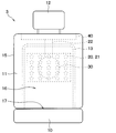
- a vehicle 2 in which the seat air conditioner 1 of the present embodiment is mounted has a two-row seat, and a front seat 3 and a rear seat 4 are provided.
- the seat air conditioner 1 of this embodiment is provided in the front seat 3.
- the seat air conditioner 1 may be provided in both the driver seat and the passenger seat of the front seats 3, or may be provided in only one of them.
- the front seat 3 may be referred to as a seat
- the rear seat 4 may be referred to as a rear seat.
- a vehicle air conditioner 6 for air conditioning the interior of the vehicle is provided inside the instrument panel 5 of the vehicle 2.
- the vehicle air conditioner 6 sucks in the air outside the vehicle compartment or the air inside the vehicle compartment, and blows out the conditioned air whose temperature and humidity have been adjusted into the vehicle interior space from the air outlet 7 provided in the instrument panel 5 or the like. It is for air conditioning.
- a space in front of the seat back of the front seat 3 is referred to as a front seat space 8
- a space behind the seat back of the front seat 3 is referred to as a rear seat space 9.
- the seat provided with the seat air conditioner 1 has a seat cushion 10 and a seat back 11.
- a headrest 12 is provided above the seat back 11.
- the seat back 11 of the seat has a structure in which a pad 14 is provided on a spring (not shown) provided on the frame 13, and the entire surface is covered with a skin 15.
- the pad 14 is a member that supports the force of the occupant leaning against the seat back 11.
- a soft material for example, urethane
- the skin 15 is directly touched by the occupant.
- the part of the seating surface with which the occupant's back comes into contact is called the back part 16, and the part with which the lower half of the occupant comes into contact is called the buttocks 17.
- the seat air conditioner 1 includes an air passage 20, a blower 30, a blower 40, a guide member 50, and the like.
- the air passage 20 is composed of an air passage 21 and an air distribution duct 22 provided in the seat.
- the ventilation passage 21 is the air passage 20 formed in the pad 14 of the seat.
- One side of the ventilation passage 21 is open to the skin 15 side forming the back portion 16 of the seat.
- the other side of the ventilation path 21 is open to the suction port 31 side of the blower 30. Therefore, the ventilation passage 21 can guide the air that has passed through the outer skin 15 of the back portion 16 of the seat to the blower 30.
- the blower 30 is a device for sucking air from the skin 15 of the back portion 16 of the seat through the ventilation passage 21 and sending the air to the blowing portion 40 through the air distribution duct 22.
- a centrifugal blower such as a turbo fan, a sirocco fan, or a radial fan is used.
- the type of the blower 30 is not limited to this, and various types such as an axial flow fan, a mixed flow fan, and a cross flow fan may be used.
- a suction port packing 32 is provided between the suction port 31 of the blower 30 and the pad 14.
- the suction port packing 32 is a member that fills the gap between the blower 30 and the pad 14, and for example, one obtained by compressing porous urethane is used.
- the air distribution duct 22 is a structural member that forms the air passage 20 that connects the blower 30 and the blowout unit 40. One end of the air distribution duct 22 is connected to the air outlet 33 of the blower 30. The other end of the air distribution duct 22 is connected to the blowout part 40. Therefore, the air distribution duct 22 can guide the air blown from the air outlet 33 of the blower 30 to the blowout portion 40.
- a duct packing 23 is provided between the air distribution duct 22 and the blowout portion 40.
- the duct packing 23 is a member that fills the gap between the air distribution duct 22 and the blowout portion 40, and for example, one obtained by compressing porous urethane is used.
- the blowout portion 40 is provided in an upper portion of the seatback 11.
- the blowout portion 40 is a structural member for forming an outlet 41 that blows out the air supplied from the air distribution duct 22. As shown in FIGS. 3 and 7, the blowout portion 40 is formed to have a large physique in the vehicle width direction. Therefore, the blowing portion 40 occupies most of the lateral width of the seat back 11.
- the air outlet 41 formed in the air outlet 40 is also formed in a wide range in the vehicle width direction. Therefore, the air outlet 41 occupies most of the seat back 11 in the vehicle width direction.
- the air outlet 41 is formed so as to blow the air flowing through the air passage 20 toward the rear of the passenger compartment along the upper surface of the seat (hereinafter referred to as the seat upper surface 18).
- the angle ⁇ formed by the surface of the seat upper surface 18 on the front side of the air outlet 41 and the wall surface on the front side of the air outlet 41 is an acute angle.
- the angle ⁇ formed by the surface of the seat upper surface 18 on the rear side of the air outlet 41 and the wall surface on the rear side of the air outlet 41 is an obtuse angle.
- the blowout unit 40 may be provided with an adjusting mechanism 42 for adjusting the wind direction of the blown air blown from the blowout port 41 to the rear of the vehicle interior, if necessary.
- the width W1 of the adjusting mechanism 42 is smaller than the width W2 of the outlet 41.
- the guide member 50 is provided on the vehicle rear side with respect to the air outlet 41.
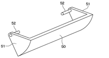
- the guide member 50 of this embodiment is formed in an arcuate cross section.
- the guide member 50 is formed so as to extend in the vehicle width direction.
- the width W3 of the guide member 50 is longer than the width W2 of the outlet 41. Therefore, as shown in FIG. 7, the width W3 of the guide member 50>the width W2 of the outlet 41>the width W1 of the adjusting mechanism 42.
- the guide member 50 is rotatably provided around a rotation shaft 52 of a support body 51 provided at both ends in the width direction thereof.
- the guide member 50 may be configured to rotate by a manual operation of an occupant, or may be configured to rotate by an electric motor (not shown).
- the guide member 50 is configured to be displaceable between a first state and a second state described below.
- the first state is a state in which the blown air blown out from the blowout port 41 allows ambient air to be blown and is sent to the rear of the passenger compartment.
- the second state is a state in which the air blown out from the air outlet 41 is guided toward the vehicle ceiling side or the vehicle floor side.
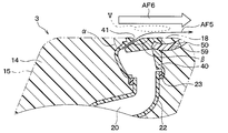
- FIG. 4 shows an example of the first state of the guide member 50.
- the guide member 50 is stored in the storage space 59 provided in the seat.
- the guide member 50 is brought into a state in which the air blown out from the air outlet 41 is allowed to be blown toward the rear of the passenger compartment by taking in the surrounding air.
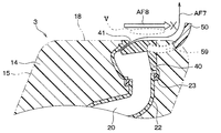
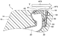
- FIG. 5 shows an example of the second state of the guide member 50.
- the guide member 50 In the second state, the guide member 50 is at least partially exposed from the storage space 59. Then, in the second state, the guide member 50 of the present embodiment has a shape that extends from the seat upper surface 18 to the ceiling side at the vehicle rear side from the air outlet 41. As a result, the guide member 50 has a shape capable of guiding the flow of air blown from the outlet 41 to the rear of the vehicle interior toward the vehicle ceiling.
- the operation of the seat air conditioner 1 of this embodiment will be described.
- air is sucked into the ventilation passage 21 via the skin 15 forming the back portion 16 of the seat.
- the air flowing through the ventilation passage 21 is collected by the suction port 31 of the blower 30.
- the air blown from the air outlet 33 of the blower 30 to the air distribution duct 22 flows through the air passage 20 in the air distribution duct 22 to the blowing portion 40.
- the air that has flown into the blowout portion 40 is blown out into the vehicle interior from the blowout port 41.
- the air blown out from the air outlet 41 flows rearward in the vehicle compartment along the seat upper surface 18 as indicated by an arrow AF5.
- the air around the blowing air flowing along the seat upper surface 18 that is, the air in the vicinity of the blowing air and the air in front of the blowing air
- the flow of air entrained in the blowing air is referred to as "entrainment wind”.
- the viscosity of air is schematically indicated by the broken line V
- the entrained wind is indicated by the arrow AF6.
- the seat air conditioner 1 sets the guide member 50 in the first state, so that, for example, when there are occupants in both the front seats 3 and the rear seats 4, both the front seat space 8 and the rear seat space 9 are instructed. You can increase comfort.
- the guide member 50 when the guide member 50 is in the second state, the blown air blown out from the blowout port 41 flows along the seat upper surface 18 as shown by an arrow AF7, and then, is guided.
- the member 50 guides the vehicle to the ceiling side.
- the wind guided by the guide member 50 forms an air curtain as a wall of air that partitions the front seat space 8 and the rear seat space 9. Therefore, as shown by the arrow AF8, the air around the blown air flowing along the seat upper surface 18 is blocked from flowing toward the rear of the passenger compartment.
- the seat air conditioner 1 can improve the comfort of the front seat space 8 and reduce the energy consumed by the vehicle air conditioner 6 for cooling the passenger compartment by setting the guide member 50 to the second state. it can.
- blowout section 400 provided in the seat air conditioner of the comparative example will be described.
- the blowing unit 400 included in the seat air conditioner of the comparative example is developed by the same applicant as the present disclosure, and is not a known technique at the time of filing the present disclosure.
- the blowing section 400 included in the seat air conditioner of the comparative example does not include the guide member 50. Therefore, also in the seat air conditioner of the comparative example, when the blower 30 is driven, as in the first embodiment, the air around the air is caught by the blown air blown from the blowout port 41 and blown to the rear of the passenger compartment. It Therefore, the air in the front seat space 8 is blown to the rear seat space 9, so that the comfort of both the front seat space 8 and the rear seat space 9 can be enhanced.
- the blowing section 400 of the comparative example includes the adjusting mechanism 42, the occupant seated in the rear seat 4 can adjust the wind direction of the blowing air blown out from the blowout port 41.
- the seat air conditioner of the comparative example when a passenger seated in the front seat 3 uses this device, the air in the front seat space 8 is blown to the rear seat space 9 regardless of whether or not the passenger in the rear seat 4 is present. Will end up. Therefore, when the seat air conditioner of the comparative example is used, the air in both the front seat space 8 and the rear seat space 9 is cooled even when there is no passenger in the rear seat 4, so that the vehicle air conditioner 6 operates in the vehicle. There is a problem in that energy consumed for indoor cooling is wasted.
- the seat air conditioner 1 of the above-described first embodiment has the following operational effects.
- the seat air conditioner 1 of the first embodiment and the seat air conditioner of the comparative example both improve the comfort of the occupant by sucking in the stuffy air between the occupant seated on the seat and the back of the seat. It has a function as SVS (abbreviation of seat ventilation system). Further, in all of these seat air conditioners, the air in the front seat space 8 is blown to the rear seat space 9 to enhance the comfort of both the front seat space 8 and the rear seat space 9. (abbreviation of circulator) has a function as.
- the air in the front seat space 8 is irrelevant regardless of the presence or absence of the passenger in the rear seat 4.
- the air is blown into the rear seat space 9. Therefore, the energy consumed by the vehicle air conditioner 6 to cool the vehicle interior may be wasted.
- the rear seat space 9 is not cooled as much as possible when the passenger in the rear seat 4 is absent, and there is a temperature difference between the front seat space 8 and the rear seat space 9.
- the guide member 50 when the occupant in the rear seat 4 is absent, the guide member 50 is set to the second state to guide the wind direction of the blown air flowing along the seat upper surface 18.
- the member 50 is configured to be changed in a substantially upward direction.
- the blown wind whose direction is changed by the guide member 50 forms an air curtain as a wall of air that partitions the front seat space 8 and the rear seat space 9.
- the blowing air deflected in the orthogonal direction by the guide member 50 prevents the air from flowing into the rear seat space 9.
- a temperature difference occurs between the front seat space 8 and the rear seat space 9. Therefore, the seat air conditioner 1 can improve the comfort of the front seat space 8 and reduce the energy consumed for cooling the passenger compartment by setting the guide member 50 to the second state.
- the width W3 of the guide member 50 is longer than the width W2 of the outlet 41.
- the width W3 of the guide member 50 needs to be longer than the width W2 of the air outlet 41. Even if the width W3 of the guide member 50 is short, the same effect is obtained, but it is considered to be not preferable because a backward flow is generated to some extent.
- the use of the adjusting mechanism 42 provided in the blowing section 40 is to adjust the blowing air to the wind direction desired by the passenger in the rear seat 4. Therefore, it can be said that the adjusting mechanism 42 assumes the occupant surrounding the rear seat 4 as the range of the wind direction adjustment, and does not assume that the blowing air is bent in a substantially orthogonal direction. Further, the width W1 of the adjusting mechanism 42 is shorter than the width W2 of the air outlet 41. This is because the adjusting mechanism 42 aims to widen the range of air blowing.
- the width W3 of the guide member 50 in the vehicle width direction is longer than the width W2 of the air outlet 41, so that the guide member 50 is blown out from the air outlet 41 in the second state. It is possible to form a wide air curtain by using almost all of the blowing air. Therefore, by further improving the effect of the air curtain, the comfort of the front seat space 8 can be further improved, and the energy consumed for cooling the vehicle interior can be further reduced.
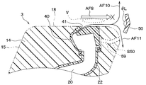
- the movable range of the guide member 50 is different from that of the first embodiment.
- the guide member 50 of the second embodiment is in a state where both the upper end and the lower end are exposed outside the sheet in the second state. In this state, the guide member 50 can guide the flow of air blown from the air outlet 41 to the rear of the vehicle compartment to the vehicle ceiling side and the vehicle floor side, respectively. Specifically, as shown by an arrow AF10, the blowing air guided to the vehicle ceiling side by the guide member 50 forms an air curtain above the seat.
- the blowing air guided to the vehicle floor side by the guide member 50 forms an air curtain below the seat.
- the cold air blown from the vehicle air conditioner 6 into the front seat space 8 has a large specific gravity, it flows downward in the vehicle interior space. Therefore, in the second embodiment, by forming the air curtain below the seat by the guide member 50, it is possible to prevent the cool air below the vehicle interior space from flowing into the rear seat space 9.
- the broken line S50 in FIG. 9 indicates the first state of the guide member 50.
- the guide member 50 In the first state, the guide member 50 can be stored in the storage space 59 provided in the seat. In the first state, the guide member 50 allows the flow of air blown from the air outlet 41 to the rear of the vehicle interior.
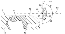
- the angle of the guide member 50 in the second state is set as follows.
- a plane connecting the upper end 56 and the lower end 57 of the surface of the guide member 50 on the vehicle front side is referred to as a first virtual surface S1.
- a plane that includes the center CL of the upper end 56 and the lower end 57 of the guide member 50 on the vehicle front side and is parallel to the seat upper surface 18 is defined as a second virtual surface S2.
- the angles formed by the first virtual surface S1 and the second virtual surface S2 are defined as ⁇ 1 and ⁇ 2.
- ⁇ 1 and ⁇ 2 are the angles of the first virtual surface S1 at the rear of the vehicle.
- the angles ⁇ 1 and ⁇ 2 of the guide member 50 in the second state are set in the range of 45° ⁇ 1 ⁇ 135° or ⁇ 45° ⁇ 2 ⁇ 135°.
- the angle of the mainstream of the blowing air that forms the air curtain is approximately 45° to 135° with respect to the seat upper surface 18, or It is possible to set approximately -45° to -135°.
- the function of the air curtain as a wall of air that separates the front seat space 8 and the rear seat space 9 from each other is enhanced, and it is possible to suppress the cold air in the front seat space 8 from moving to the rear seat space 9. is there. Therefore, the seat air conditioner 1 of the second embodiment can further enhance the comfort of the front seat space 8 and further reduce the energy consumed by the vehicle air conditioner 6 for cooling the vehicle interior.
- the guide member 50 has the angles ⁇ 1 and ⁇ 2 in the second state within the range of 45° ⁇ 1 ⁇ 135° or ⁇ 45° ⁇ 2 ⁇ 135°. Although it has been described as being set, it is not limited to this.
- the guide member 50 sets the angles ⁇ 1 and ⁇ 2 in the second state within the range of 60° ⁇ 1 ⁇ 120° or ⁇ 60° ⁇ 2 ⁇ 120°. Set. Further, it is more preferable that the guide member 50 sets the angles ⁇ 1 and ⁇ 2 in the second state to be substantially perpendicular to the seat upper surface 18.
- the third embodiment is a modification of the driving method of the guide member 50 with respect to the first embodiment and the like, and is similar to the first embodiment and the like in other respects, and therefore the parts different from the first embodiment and the like will be described. Only explained.
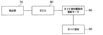
- FIG. 11 is a block diagram showing a control system of the seat air conditioner 1 of the third embodiment.
- the guide member 50 is configured to rotate by the electric motor 60 for driving the guide member.
- the vehicle 2 equipped with the seat air conditioner 1 of the third embodiment is provided with a detection unit 70 for detecting the presence or absence of an occupant seated in the rear seat 4.
- the detection unit 70 include a courtesy switch that detects opening and closing of a rear door, a seating sensor provided in the rear seat 4, or an in-vehicle camera.
- the signal output from the detection unit 70 is transmitted to a control device (ECU: Electronic Control Unit) 80.
- ECU Electronic Control Unit
- the control device 80 includes a processor that performs control processing and arithmetic processing, a microcomputer that stores a storage unit such as ROM and RAM that stores programs and data, and its peripheral circuits.
- the storage unit of the control device 80 is composed of a non-transitional substantive storage medium.
- the control device 80 controls the operation of the electric motor 60 for driving the guide member, which is connected to the output port, according to the presence or absence of an occupant detected by the detection unit 70. Specifically, the control device 80 sets the guide member 50 to the first state when the detection unit 70 detects that the occupant is seated in the rear seat 4. On the other hand, when the detection unit 70 detects that the occupant is not seated in the rear seat 4, the control device 80 places the guide member 50 in the second state.
- the control device 80 switches the guide member 50 to the first state or the second state depending on the presence/absence of an occupant seated in the rear seat 4.
- the guide member 50 automatically switches between the first state and the second state depending on whether or not there is an occupant seated in the rear seat 4. Therefore, the seat air conditioner 1 of the third embodiment can save the labor of the occupant who moves the guide member 50, improve the comfort of the front seat space 8, and reduce the energy consumed for cooling the passenger compartment.
- the fourth to sixth embodiments are different from the first embodiment and the like in the shape of the guide member 50 and the like, and are otherwise similar to the first embodiment and the like. Only different parts will be described.
- the guide member 50 included in the seat air conditioner 1 of the fourth embodiment has a linear cross section. Therefore, the guide member 50 is formed in a flat plate shape.
- FIG. 12 shows the first state of the guide member 50
- FIG. 13 shows the second state of the guide member 50.
- the guide member 50 may be driven by, for example, a rack and pinion.
- the pinion 54 provided on the seat side is configured to mesh with the rack 53 provided on the guide member 50.
- the guide member 50 is displaced between the first state and the second state.
- the driving method of the guide member 50 is not limited to this, and the guide member 50 may be configured to be displaced by a manual operation of an occupant. Further, the guide member 50 may be configured to have the support bodies 51 as described in the first embodiment at both ends in the width direction.
- the guide member 50 included in the seat air conditioner 1 according to the fifth embodiment has a cross-section formed by combining two line segments.
- the angle ⁇ L formed by the two line segments is 90° ⁇ L ⁇ 180° on the vehicle front side.
- the first state of the guide member 50 is shown by a broken line S50, and the second state of the guide member 50 is shown by a solid line.
- the driving method of the guide member 50 may be configured to be displaced by a manual operation of an occupant as in the above-described embodiments, or may be configured to be rotated by an electric motor 60 (not shown). Good.
- the seat air conditioner 1 of the fifth embodiment can also achieve the same effects as those of the above-described first to fourth embodiments.
- the guide member 50 included in the seat air conditioner 1 of the sixth embodiment has a shape having a plurality of uneven portions 55.
- the plurality of uneven portions 55 are provided on the front surface of the vehicle when the guide member 50 is in the second state.
- the first state of the guide member 50 is shown by a broken line S50
- the second state of the guide member 50 is shown by a solid line.
- the driving method of the guide member 50 may be configured to be displaced by a manual operation of an occupant as in the above-described embodiments, or may be configured to be rotated by an electric motor 60 (not shown). Good.
- the seat air conditioner 1 of the sixth embodiment can also achieve the same effects as those of the above-described first to fifth embodiments.
- control device and the method thereof described in the present disclosure are realized by a dedicated computer provided by configuring a processor and a memory programmed to execute one or more functions embodied by a computer program. May be done.
- control device and the method thereof described in the present disclosure may be realized by a dedicated computer provided by configuring a processor with one or more dedicated hardware logic circuits.
- control device and the method thereof described in the present disclosure are based on a combination of a processor and a memory programmed to execute one or a plurality of functions and a processor configured by one or more hardware logic circuits. It may be realized by one or more dedicated computers configured.
- the computer program may be stored in a computer-readable non-transition tangible recording medium as an instruction executed by a computer.
- the seat air conditioner 1 is described as being mounted on the vehicle 2 having two rows of seats, but the present invention is not limited to this.
- the seat air conditioner 1 may be installed in a vehicle 2 having three or more rows of seats. In that case, the seat air conditioner 1 may be provided in the front seat 3 or in the seats in the second and subsequent rows from the front.
- the shape of the guide member 50 included in the seat air conditioner 1 is an arc cross section, a straight cross section (that is, a flat plate shape), and a cross section having a combination of two line segments, or
- the shape having the uneven portion 55 on the surface has been described, but the shape is not limited to this.
- Various shapes and materials of the guide member 50 and the support body 51 can be adopted.
- the air passage 20 included in the seat air conditioner 1 is described as including the air passage 21 and the air distribution duct 22 provided in the seat, but the present invention is not limited to this.
- the air passage 20 included in the seat air conditioner 1 may have any configuration as long as it can guide the wind sucked from the skin 15 of the seat to the blowout portion 40.
- the seat air conditioner 1 is described as sucking air from the back portion 16 of the seating surface of the seat, but the present invention is not limited to this.
- the position where the seat air conditioner 1 sucks in air may be any position on the seat.
- the guide member 50 is stored in the storage space 59 provided in the seat in the first state, but the configuration is not limited to this.
- the guide member 50 may be configured to move below the seat upper surface 18 along the seat back surface skin 15, for example.
- the seat air conditioner mounted on the vehicle includes an air passage, a blower, an outlet, and a guide member.
- the air passage is provided in a vehicle seat.
- the blower blows air through the air passage.
- the air outlet blows the air flowing through the air passage toward the rear of the passenger compartment along the upper surface of the seat.
- the guide member is provided behind the vehicle with respect to the air outlet.
- the guide member is in a first state in which the blown air blown from the blowout port allows ambient air to be blown to the rear of the passenger compartment, and the blown wind blown from the blowout port is on the vehicle ceiling side or It is configured to be displaceable into a second state in which the vehicle is guided toward the floor side.
- the air around the blowout air blown out from the blowout port is caught in the blowout air due to the viscosity of the air and blown toward the rear of the vehicle interior. Is configured.
- the air blown from the air outlet and guided by the guide member to the vehicle ceiling side or the vehicle floor side causes the air around the blown air to flow toward the rear of the vehicle compartment. It is configured to be blocked.
- the air blown out from the air outlet flows toward the rear of the passenger compartment along the upper surface of the seat.
- the air around the blowing air that flows along the upper surface of the seat that is, the air in the vicinity of the blowing air and the air in front of the blowing air
- the cold air generated by the vehicle air conditioner and blown into the front seat space is entrained by the air blown out from the seat air conditioner, and becomes entrained air and is blown to the rear seat space. Therefore, in this seat air conditioner, by setting the guide member in the first state, it is possible to enhance the comfort of both the front seat space and the rear seat space, for example, when there are occupants in both the front seats and the rear seats. it can.
- the guide member when the guide member is in the second state, the air blown out from the air outlet flows along the upper surface of the seat and then is guided to the vehicle ceiling side or the vehicle floor side by the guide member.
- the wind guided by the guide member forms an air curtain as a wall of air that partitions the front seat space and the rear seat space.
- the air around the blowing air flowing along the upper surface of the seat is blocked from flowing toward the rear of the passenger compartment. Therefore, for example, when there is an occupant only in the front seat, the cool air in the front seat space is suppressed from being blown to the rear seat space, and a temperature difference occurs between the front seat space and the rear seat space. Therefore, in this seat air conditioner, by setting the guide member in the second state, it is possible to improve comfort of the front seat space and reduce energy consumed for cooling the vehicle interior.
- the air passage is configured so that the air sucked from the back of the seating surface of the seat flows to the air outlet.
- the stuffy air between the occupant sitting on the seat provided with the seat air conditioner and the back of the seat is sucked into the air passage of the seat air conditioner.
- the seat air conditioner can improve the comfort of the occupant sitting on the seat.
- the seat air conditioner uses the air blown from the air outlet to enhance the comfort of the rear seat space when there is an occupant in the rear seat, and above the seat or when there is no occupant in the rear seat.
- An air curtain can be formed below.
- the width of the guide member is longer than the width of the air outlet.
- the guide member when the guide member is in the second state, the first virtual surface connecting the upper end and the lower end of the vehicle front side surface of the guide member, and the upper surface of the seat including the center of the upper end and the lower end of the first virtual surface.
- the angles formed by the second parallel virtual surface are ⁇ 1 and ⁇ 2.
- the guide member is set such that the angles ⁇ 1 and ⁇ 2 in the second state are in the range of 45° ⁇ 1 ⁇ 135° or ⁇ 45° ⁇ 2 ⁇ 135°.
- the angle of the main flow forming the air curtain can be set to approximately 45° to 135° or approximately ⁇ 45° to ⁇ 135° with respect to the upper surface of the seat. Is.
- the seat air conditioner includes a detection unit that detects the presence or absence of an occupant seated in a rear seat located behind the seat in which the seat air conditioner is installed, and the presence or absence of the occupant detected by the detection unit. And a controller for controlling the drive of the guide member according to the above.
- the control device sets the guide member to the first state when the detection unit detects that the occupant is seated on the rear seat.
- the control device sets the guide member to the second state when the detection unit detects that the occupant is not seated on the rear seat.
- the control device automatically switches the guide member to the first state or the second state depending on the presence or absence of an occupant seated on the rear seat. Therefore, this seat air conditioner can save the labor of the occupant who moves the guide member, improve the comfort of the front seat space, and reduce the energy consumed for cooling the vehicle interior.
Abstract
An air passage (20) is provided in a seat (3) of a vehicle. A blower (30) sends air to the air passage (20). An air outlet (41) blows the air flowing through the air passage (20), to the back of the vehicle interior along an upper surface (18) of the seat. A guide member (50) is provided at the back of the vehicle with respect to the air outlet (41). The guide member (50) is configured to be displaceable to a first state for allowing the air blown out of the air outlet (41) to entrain the surrounding air and to be sent to the back of the vehicle interior, and a second state for guiding the air blown out of the air outlet (41) toward the ceiling of the vehicle or the floor of the vehicle.
Description
本出願は、2018年12月19日に出願された日本特許出願番号2018-237458号に基づくもので、ここにその記載内容が参照により組み入れられる。
This application is based on Japanese Patent Application No. 2018-237458 filed on December 19, 2018, the description of which is incorporated herein by reference.
本開示は、車両のシートに設けられるシート空調装置に関するものである。
The present disclosure relates to a seat air conditioner provided on a vehicle seat.
従来、車両のシートに設けられる種々のシート空調装置が知られている。
特許文献1に記載の装置は、車両の前席に設けられており、前席の着座面のうち背中部から吸い込んだ空気を、前席の側面等に設けた吹出口から車室内後方へ吹き出すように構成されている。これにより、この装置は、前席の側面等の吹出口から空気が吹き出されると、その吹き出された空気(以下、吹出風という)の周囲の空気が、空気の粘性によってその吹出風に巻き込まれて車室内後方へ送風される。そのため、車両のインストルメントパネルの内側に設けられる車両用空調装置で生成されて前席空間に吹き出された冷たい空気は、吹出風に巻き込まれて後席空間へ送風される。これにより、この装置は、車室内の前席空間と後席空間の両方の快適性を高めることができる。 Conventionally, various seat air conditioners provided on a seat of a vehicle are known.
The device described inPatent Document 1 is provided in a front seat of a vehicle, and blows air sucked from the back part of the seating surface of the front seat toward the rear of the vehicle interior from an outlet provided in a side surface of the front seat or the like. Is configured. As a result, when air is blown out from the air outlet on the side surface of the front seat or the like, the air around the blown air (hereinafter referred to as blowout air) is entrained in the blowout air due to the viscosity of the air. Is blown to the rear of the passenger compartment. Therefore, the cold air generated by the vehicle air conditioner provided inside the instrument panel of the vehicle and blown into the front seat space is caught in the blown air and blown into the rear seat space. As a result, this device can improve the comfort of both the front seat space and the rear seat space in the vehicle interior.
特許文献1に記載の装置は、車両の前席に設けられており、前席の着座面のうち背中部から吸い込んだ空気を、前席の側面等に設けた吹出口から車室内後方へ吹き出すように構成されている。これにより、この装置は、前席の側面等の吹出口から空気が吹き出されると、その吹き出された空気(以下、吹出風という)の周囲の空気が、空気の粘性によってその吹出風に巻き込まれて車室内後方へ送風される。そのため、車両のインストルメントパネルの内側に設けられる車両用空調装置で生成されて前席空間に吹き出された冷たい空気は、吹出風に巻き込まれて後席空間へ送風される。これにより、この装置は、車室内の前席空間と後席空間の両方の快適性を高めることができる。 Conventionally, various seat air conditioners provided on a seat of a vehicle are known.
The device described in
なお、前席空間とは、車室内空間の中で前席の着座面のうち背中部よりも前方の空間をいい、後席空間とは、車室内空間の中で前席の着座面のうち背中部よりも後方の空間をいう。
Note that the front seat space refers to a space in front of the back part of the seating surface of the front seat in the vehicle interior space, and the rear seat space refers to the seating surface of the front seat in the vehicle interior space. The space behind the back.
しかしながら、上述した特許文献1に記載の装置では、前席に着座した乗員がこの装置を使用すると、後席の乗員の有無に関わらず、車両用空調装置から前席空間に吹き出された冷たい空気が、後席空間へ送風されてしまうことが考えられる。そのため、この装置を使用すると、後席に乗員がいないときにも、前席空間と後席空間の両方の空気が冷やされることになるので、車室内冷房に消費されるエネルギが無駄になるといった課題が考えられる。
However, in the device described in Patent Document 1 described above, when an occupant seated in the front seat uses this device, regardless of the presence or absence of the occupant in the rear seat, the cold air blown from the vehicle air-conditioning device to the front seat space. However, it is possible that air will be blown into the rear seat space. Therefore, when this device is used, the air in both the front seat space and the rear seat space is cooled even when there is no passenger in the rear seat, and the energy consumed for cooling the vehicle interior is wasted. Issues can be considered.
本開示は、前席空間と後席空間の両方の快適性を高める状態と、車室内冷房に消費されるエネルギを低減する状態とを切り替え可能なシート空調装置を提供することを目的とする。
The present disclosure aims to provide a seat air conditioner capable of switching between a state in which the comfort of both the front seat space and the rear seat space are enhanced and a state in which energy consumed for cooling the vehicle interior is reduced.
本開示の1つの観点によれば、
車両に搭載されるシート空調装置において、
車両のシートに設けられる空気通路と、
空気通路に空気を流す送風機と、
空気通路を流れる空気をシートの上面に沿うように車室内後方へ吹き出す吹出口と、
吹出口に対し車両後方に設けられ、吹出口から吹き出された吹出風が周囲の空気を巻き込んで車室内後方へ送風されることを許容する第1状態と、吹出口から吹き出された吹出風が車両天井側または車両床側へ向かうように案内する第2状態とに変位可能に構成されているガイド部材と、を備える。 According to one aspect of the disclosure,
In the seat air conditioner installed in the vehicle,
An air passage provided in a vehicle seat,
A blower that blows air through the air passage,
An air outlet that blows the air flowing through the air passage toward the rear of the passenger compartment along the upper surface of the seat,
The first state, which is provided on the rear side of the vehicle with respect to the air outlet and allows the air blown from the air outlet to be blown toward the rear of the vehicle by entraining the surrounding air, and the air blown from the air outlet. A guide member configured to be displaceable in a second state in which the guide member is guided toward the vehicle ceiling side or the vehicle floor side.
これによれば、ガイド部材が第1状態のとき、吹出口から吹き出される吹出風は、シートの上面に沿って車室内後方へ流れる。その際、シート上面に沿って流れる吹出風の周囲の空気(すなわち、吹出風の近傍にある空気やその前側にある空気)も、空気の粘性によってその吹出風に巻き込まれて車室内後方へ送風される。以下、吹出風に巻き込まれる空気の流れを「巻き込み風」という。すなわち、車両のインストルメントパネルの内側に設けられる車両用空調装置で生成されて前席空間に吹き出された冷たい空気は、シート空調装置から吹き出される吹出風に巻き込まれ、巻き込み風となって後席空間へ送風される。したがって、このシート空調装置は、ガイド部材を第1状態とすることで、例えば前席と後席の両方に乗員がいる場合など、前席空間と後席空間の両方の快適性を高めることができる。
According to this, when the guide member is in the first state, the air blown out from the air outlet flows toward the rear of the passenger compartment along the upper surface of the seat. At that time, the air around the blowing air that flows along the upper surface of the seat (that is, the air in the vicinity of the blowing air and the air in front of the blowing air) is also entrained in the blowing air due to the viscosity of the air and blown toward the rear of the vehicle compartment. To be done. Hereinafter, the flow of air entrained in the blowing air is referred to as "entrainment wind". That is, the cold air generated in the vehicle air conditioner provided inside the instrument panel of the vehicle and blown into the front seat space is caught in the blown air blown from the seat air conditioner, and becomes a trapped wind. The air is blown to the seat space. Therefore, in this seat air conditioner, by setting the guide member in the first state, it is possible to enhance the comfort of both the front seat space and the rear seat space, for example, when there are occupants in both the front seats and the rear seats. it can.
一方、ガイド部材が第2状態のとき、吹出口から吹き出される吹出風は、シート上面に沿って流れた後、ガイド部材によって車両天井側または車両床側へ案内される。そして、ガイド部材により案内された風は、前席空間と後席空間とを仕切る空気の壁としてのエアカーテンを形成する。これにより、シート上面に沿って流れる吹出風の周囲にある空気は、車室内後方へ向かう流れが遮断される。そのため、例えば前席のみに乗員がいる場合など、前席空間の冷たい空気が後席空間に送風されることが抑制され、前席空間と後席空間とに温度差が発生する。したがって、このシート空調装置は、ガイド部材を第2状態とすることで、前席空間の快適性を高めると共に、車室内冷房に消費されるエネルギを低減することができる。
On the other hand, when the guide member is in the second state, the air blown out from the air outlet flows along the upper surface of the seat and then is guided to the vehicle ceiling side or the vehicle floor side by the guide member. The wind guided by the guide member forms an air curtain as a wall of air that partitions the front seat space and the rear seat space. As a result, the air around the blowing air flowing along the upper surface of the seat is blocked from flowing toward the rear of the passenger compartment. Therefore, for example, when there is an occupant only in the front seat, the cool air in the front seat space is suppressed from being blown to the rear seat space, and a temperature difference occurs between the front seat space and the rear seat space. Therefore, in this seat air conditioner, by setting the guide member in the second state, it is possible to improve comfort of the front seat space and reduce energy consumed for cooling the vehicle interior.
なお、各構成要素等に付された括弧付きの参照符号は、その構成要素等と後述する実施形態に記載の具体的な構成要素等との対応関係の一例を示すものである。
Note that the reference numerals in parentheses attached to the respective components and the like indicate an example of a correspondence relationship between the components and the like and specific components and the like described in the embodiments described later.
以下、本開示の実施形態について図面を参照しつつ説明する。なお、以下の各実施形態相互において、互いに同一もしくは均等である部分には、同一符号を付し、その説明を省略する。
Hereinafter, embodiments of the present disclosure will be described with reference to the drawings. In each of the following embodiments, the same or equivalent portions will be denoted by the same reference numerals, and description thereof will be omitted.
(第1実施形態)
第1実施形態について図面を参照しつつ説明する。図1に示すように、本実施形態のシート空調装置1が搭載される車両2は、2列シートになっており、前席3と後席4が設けられている。本実施形態のシート空調装置1は、前席3に設けられている。シート空調装置1は、前席3のうち運転席または助手席の両方に設けられていてもよく、または、その一方のみに設けられていてもよい。なお、本明細書において、前席3をシートと呼び、後席4を後部シートと呼ぶことがある。 (First embodiment)
The first embodiment will be described with reference to the drawings. As shown in FIG. 1, a vehicle 2 in which theseat air conditioner 1 of the present embodiment is mounted has a two-row seat, and a front seat 3 and a rear seat 4 are provided. The seat air conditioner 1 of this embodiment is provided in the front seat 3. The seat air conditioner 1 may be provided in both the driver seat and the passenger seat of the front seats 3, or may be provided in only one of them. In the present specification, the front seat 3 may be referred to as a seat, and the rear seat 4 may be referred to as a rear seat.
第1実施形態について図面を参照しつつ説明する。図1に示すように、本実施形態のシート空調装置1が搭載される車両2は、2列シートになっており、前席3と後席4が設けられている。本実施形態のシート空調装置1は、前席3に設けられている。シート空調装置1は、前席3のうち運転席または助手席の両方に設けられていてもよく、または、その一方のみに設けられていてもよい。なお、本明細書において、前席3をシートと呼び、後席4を後部シートと呼ぶことがある。 (First embodiment)
The first embodiment will be described with reference to the drawings. As shown in FIG. 1, a vehicle 2 in which the
この車両2のインストルメントパネル5の内側には、車室内を空調するための車両用空調装置6が設けられている。車両用空調装置6は、車室外空気または車室内空気を吸い込んで、温度および湿度を調整した空調風を、インストルメントパネル5等に設けられた吹出口7から車室内空間に吹き出し、車室内の空調を行うものである。
以下の説明において、車室内空間の中で、前席3のシートバックよりも前方の空間を前席空間8といい、前席3のシートバックよりも後方の空間を後席空間9ということとする。 Inside theinstrument panel 5 of the vehicle 2, a vehicle air conditioner 6 for air conditioning the interior of the vehicle is provided. The vehicle air conditioner 6 sucks in the air outside the vehicle compartment or the air inside the vehicle compartment, and blows out the conditioned air whose temperature and humidity have been adjusted into the vehicle interior space from the air outlet 7 provided in the instrument panel 5 or the like. It is for air conditioning.
In the following description, in the vehicle interior space, a space in front of the seat back of thefront seat 3 is referred to as a front seat space 8, and a space behind the seat back of the front seat 3 is referred to as a rear seat space 9. To do.
以下の説明において、車室内空間の中で、前席3のシートバックよりも前方の空間を前席空間8といい、前席3のシートバックよりも後方の空間を後席空間9ということとする。 Inside the
In the following description, in the vehicle interior space, a space in front of the seat back of the
図2および図3に示すように、シート空調装置1が設けられるシートは、シートクッション10とシートバック11を有している。なお、シートバック11の上方にはヘッドレスト12が設けられている。シートのシートバック11は、フレーム13に設けられた図示しないスプリングにパッド14が設けられ、その全体が表皮15によって覆われた構成となっている。パッド14は、乗員がシートバック11に凭れ掛かる力を支える部材である。パッド14として、力を分散する柔らかい材質(例えばウレタン)が用いられる。表皮15は、乗員が直接触れるものである。表皮15として、例えば、空気を通すために孔を空けた革製、合皮製もしくは布製(例えばファブリック)のものが用いられる。以下の説明において、シートの表皮15の中で乗員が接する着座面のうち、乗員の背中が接する部位を背中部16と呼び、乗員の下半身が接する部位を臀部17と呼ぶ。
As shown in FIGS. 2 and 3, the seat provided with the seat air conditioner 1 has a seat cushion 10 and a seat back 11. A headrest 12 is provided above the seat back 11. The seat back 11 of the seat has a structure in which a pad 14 is provided on a spring (not shown) provided on the frame 13, and the entire surface is covered with a skin 15. The pad 14 is a member that supports the force of the occupant leaning against the seat back 11. As the pad 14, a soft material (for example, urethane) that disperses the force is used. The skin 15 is directly touched by the occupant. As the outer skin 15, for example, a leather, a synthetic leather or a cloth (for example, fabric) having holes for allowing air to pass is used. In the following description, of the seating surface of the seat 15 on which the occupant comes into contact, the part of the seating surface with which the occupant's back comes into contact is called the back part 16, and the part with which the lower half of the occupant comes into contact is called the buttocks 17.
シート空調装置1は、空気通路20、送風機30、吹出部40、および、ガイド部材50などを備えている。
空気通路20は、シートに設けられる通風路21と配風ダクト22により構成されている。通風路21は、シートのパッド14に形成される空気通路20である。通風路21の一方の側は、シートの背中部16を形成する表皮15側に開口している。通風路21の他方の側は、送風機30の吸込口31側に開口している。そのため、通風路21は、シートの背中部16の表皮15を通過した空気を送風機30へ導くことが可能である。 Theseat air conditioner 1 includes an air passage 20, a blower 30, a blower 40, a guide member 50, and the like.
Theair passage 20 is composed of an air passage 21 and an air distribution duct 22 provided in the seat. The ventilation passage 21 is the air passage 20 formed in the pad 14 of the seat. One side of the ventilation passage 21 is open to the skin 15 side forming the back portion 16 of the seat. The other side of the ventilation path 21 is open to the suction port 31 side of the blower 30. Therefore, the ventilation passage 21 can guide the air that has passed through the outer skin 15 of the back portion 16 of the seat to the blower 30.
空気通路20は、シートに設けられる通風路21と配風ダクト22により構成されている。通風路21は、シートのパッド14に形成される空気通路20である。通風路21の一方の側は、シートの背中部16を形成する表皮15側に開口している。通風路21の他方の側は、送風機30の吸込口31側に開口している。そのため、通風路21は、シートの背中部16の表皮15を通過した空気を送風機30へ導くことが可能である。 The
The
送風機30は、シートの背中部16の表皮15から通風路21を介して空気を吸込み、その空気を配風ダクト22を介して吹出部40へ送るための装置である。送風機30として、例えば、ターボファン、シロッコファン、ラジアルファンなどの遠心送風機が用いられる。なお、送風機30の種類はこれに限らず、軸流ファン、斜流ファン、横流ファンなど種々のものを使用してもよい。送風機30の吸込口31とパッド14との間には、吸込口パッキン32が設けられる。吸込口パッキン32は、送風機30とパッド14との隙間を埋める部材であり、例えば、多孔質ウレタンを圧縮したものが用いられる。
The blower 30 is a device for sucking air from the skin 15 of the back portion 16 of the seat through the ventilation passage 21 and sending the air to the blowing portion 40 through the air distribution duct 22. As the blower 30, for example, a centrifugal blower such as a turbo fan, a sirocco fan, or a radial fan is used. The type of the blower 30 is not limited to this, and various types such as an axial flow fan, a mixed flow fan, and a cross flow fan may be used. A suction port packing 32 is provided between the suction port 31 of the blower 30 and the pad 14. The suction port packing 32 is a member that fills the gap between the blower 30 and the pad 14, and for example, one obtained by compressing porous urethane is used.
配風ダクト22は、送風機30と吹出部40を繋ぐ空気通路20を形成する構造部材である。配風ダクト22の一方の端部は、送風機30の空気出口33に接続されている。配風ダクト22の他方の端部は、吹出部40に接続されている。そのため、配風ダクト22は、送風機30の空気出口33から吹き出された空気を吹出部40へ導くことが可能である。配風ダクト22と吹出部40との間には、ダクトパッキン23が設けられる。ダクトパッキン23は、配風ダクト22と吹出部40との隙間を埋める部材であり、例えば、多孔質ウレタンを圧縮したものが用いられる。
The air distribution duct 22 is a structural member that forms the air passage 20 that connects the blower 30 and the blowout unit 40. One end of the air distribution duct 22 is connected to the air outlet 33 of the blower 30. The other end of the air distribution duct 22 is connected to the blowout part 40. Therefore, the air distribution duct 22 can guide the air blown from the air outlet 33 of the blower 30 to the blowout portion 40. A duct packing 23 is provided between the air distribution duct 22 and the blowout portion 40. The duct packing 23 is a member that fills the gap between the air distribution duct 22 and the blowout portion 40, and for example, one obtained by compressing porous urethane is used.
吹出部40は、シートバック11の中で上方の部位に設けられている。吹出部40は、配風ダクト22から供給された空気を吹き出す吹出口41を形成するための構造部材である。図3および図7に示すように、吹出部40は、車幅方向の体格が大きく形成されている。そのため、吹出部40は、シートバック11の横幅の大部分を占めている。そして、吹出部40に形成される吹出口41も、車幅方向に広い範囲で形成されている。そのため、吹出口41は、シートバック11の車幅方向の大部分を占めている。
The blowout portion 40 is provided in an upper portion of the seatback 11. The blowout portion 40 is a structural member for forming an outlet 41 that blows out the air supplied from the air distribution duct 22. As shown in FIGS. 3 and 7, the blowout portion 40 is formed to have a large physique in the vehicle width direction. Therefore, the blowing portion 40 occupies most of the lateral width of the seat back 11. The air outlet 41 formed in the air outlet 40 is also formed in a wide range in the vehicle width direction. Therefore, the air outlet 41 occupies most of the seat back 11 in the vehicle width direction.
また、吹出口41は、空気通路20を流れる空気をシートの上面(以下、シート上面18という)に沿うように車室内後方へ吹き出すように形成されている。具体的には、図4に示すように、シート上面18のうち吹出口41より前側の面と、吹出口41の前側の壁面とのなす角αは鋭角となっている。また、シート上面18のうち吹出口41より後側の面と、吹出口41の後側の壁面とのなす角βは鈍角となっている。
Further, the air outlet 41 is formed so as to blow the air flowing through the air passage 20 toward the rear of the passenger compartment along the upper surface of the seat (hereinafter referred to as the seat upper surface 18). Specifically, as shown in FIG. 4, the angle α formed by the surface of the seat upper surface 18 on the front side of the air outlet 41 and the wall surface on the front side of the air outlet 41 is an acute angle. Further, the angle β formed by the surface of the seat upper surface 18 on the rear side of the air outlet 41 and the wall surface on the rear side of the air outlet 41 is an obtuse angle.
なお、図7に示すように、吹出部40には、必要に応じて、吹出口41から車室内後方へ吹出された吹出風の風向きを調整するための調節機構42を設けてもよい。なお、この調節機構42の幅W1は、吹出口41の幅W2より小さいものとなっている。
ガイド部材50は、吹出口41に対し車両後方に設けられている。本実施形態のガイド部材50は、断面が円弧状に形成されている。また、ガイド部材50は、車幅方向に延びるように形成されている。そして、ガイド部材50の幅W3は、吹出口41の幅W2より長いものとなっている。したがって、図7に示すように、ガイド部材50の幅W3>吹出口41の幅W2>調節機構42の幅W1 の関係になっている。 Note that, as shown in FIG. 7, theblowout unit 40 may be provided with an adjusting mechanism 42 for adjusting the wind direction of the blown air blown from the blowout port 41 to the rear of the vehicle interior, if necessary. The width W1 of the adjusting mechanism 42 is smaller than the width W2 of the outlet 41.
Theguide member 50 is provided on the vehicle rear side with respect to the air outlet 41. The guide member 50 of this embodiment is formed in an arcuate cross section. The guide member 50 is formed so as to extend in the vehicle width direction. The width W3 of the guide member 50 is longer than the width W2 of the outlet 41. Therefore, as shown in FIG. 7, the width W3 of the guide member 50>the width W2 of the outlet 41>the width W1 of the adjusting mechanism 42.
ガイド部材50は、吹出口41に対し車両後方に設けられている。本実施形態のガイド部材50は、断面が円弧状に形成されている。また、ガイド部材50は、車幅方向に延びるように形成されている。そして、ガイド部材50の幅W3は、吹出口41の幅W2より長いものとなっている。したがって、図7に示すように、ガイド部材50の幅W3>吹出口41の幅W2>調節機構42の幅W1 の関係になっている。 Note that, as shown in FIG. 7, the
The
図6に示すように、ガイド部材50は、その幅方向の両端に設けられた支持体51の回転軸52を中心として回転可能に設けられている。なお、ガイド部材50は、乗員の手動操作により回転するように構成されていてもよく、または、図示しない電動モータにより回転するように構成されていてもよい。
As shown in FIG. 6, the guide member 50 is rotatably provided around a rotation shaft 52 of a support body 51 provided at both ends in the width direction thereof. The guide member 50 may be configured to rotate by a manual operation of an occupant, or may be configured to rotate by an electric motor (not shown).
図4および図5に示すように、ガイド部材50は、次に述べる第1状態と第2状態とに変位可能に構成されている。第1状態とは、吹出口41から吹き出された吹出風が周囲の空気を巻き込んで車室内後方へ送風されることを許容する状態である。第2状態とは、吹出口41から吹き出された吹出風が車両天井側または車両床側へ向かうように案内する状態である。
As shown in FIGS. 4 and 5, the guide member 50 is configured to be displaceable between a first state and a second state described below. The first state is a state in which the blown air blown out from the blowout port 41 allows ambient air to be blown and is sent to the rear of the passenger compartment. The second state is a state in which the air blown out from the air outlet 41 is guided toward the vehicle ceiling side or the vehicle floor side.
図4は、ガイド部材50の第1状態の一例を示している。ガイド部材50は、第1状態のとき、シートに設けられた格納スペース59に格納される。これにより、ガイド部材50は、吹出口41から吹き出された吹出風が周囲の空気を巻き込んで車室内後方へ送風されることを許容する状態となる。
FIG. 4 shows an example of the first state of the guide member 50. In the first state, the guide member 50 is stored in the storage space 59 provided in the seat. As a result, the guide member 50 is brought into a state in which the air blown out from the air outlet 41 is allowed to be blown toward the rear of the passenger compartment by taking in the surrounding air.
一方、図5は、ガイド部材50の第2状態の一例を示している。ガイド部材50は、第2状態のとき、格納スペース59から少なくとも一部が露出した状態となる。そして、本実施形態のガイド部材50は、第2状態のとき、吹出口41より車両後方で、シート上面18から天井側へ延びる形状となる。これにより、ガイド部材50は、吹出口41から車室内後方へ吹き出される空気の流れを車両天井側へ案内可能な形状となる。
On the other hand, FIG. 5 shows an example of the second state of the guide member 50. In the second state, the guide member 50 is at least partially exposed from the storage space 59. Then, in the second state, the guide member 50 of the present embodiment has a shape that extends from the seat upper surface 18 to the ceiling side at the vehicle rear side from the air outlet 41. As a result, the guide member 50 has a shape capable of guiding the flow of air blown from the outlet 41 to the rear of the vehicle interior toward the vehicle ceiling.
次に、本実施形態のシート空調装置1の作動を説明する。
シート空調装置1の送風機30が駆動すると、図2の矢印AF1に示すように、シートの背中部16を形成する表皮15を介して通風路21に空気が吸い込まれる。矢印AF2、AF3に示すように、通風路21を流れる空気は、送風機30の吸込口31に集風される。次に、矢印AF4に示すように、送風機30の空気出口33から配風ダクト22に吹き出された空気は、配風ダクト22の中の空気通路20を通って吹出部40に流れる。そして、矢印AF5に示すように、吹出部40に流入した空気は、吹出口41から車室内に吹き出される。 Next, the operation of theseat air conditioner 1 of this embodiment will be described.
When theblower 30 of the seat air conditioner 1 is driven, as shown by an arrow AF1 in FIG. 2, air is sucked into the ventilation passage 21 via the skin 15 forming the back portion 16 of the seat. As indicated by arrows AF2 and AF3, the air flowing through the ventilation passage 21 is collected by the suction port 31 of the blower 30. Next, as shown by an arrow AF4, the air blown from the air outlet 33 of the blower 30 to the air distribution duct 22 flows through the air passage 20 in the air distribution duct 22 to the blowing portion 40. Then, as indicated by an arrow AF5, the air that has flown into the blowout portion 40 is blown out into the vehicle interior from the blowout port 41.
シート空調装置1の送風機30が駆動すると、図2の矢印AF1に示すように、シートの背中部16を形成する表皮15を介して通風路21に空気が吸い込まれる。矢印AF2、AF3に示すように、通風路21を流れる空気は、送風機30の吸込口31に集風される。次に、矢印AF4に示すように、送風機30の空気出口33から配風ダクト22に吹き出された空気は、配風ダクト22の中の空気通路20を通って吹出部40に流れる。そして、矢印AF5に示すように、吹出部40に流入した空気は、吹出口41から車室内に吹き出される。 Next, the operation of the
When the
図4に示すように、ガイド部材50が第1状態のとき、吹出口41から吹き出される吹出風は、矢印AF5に示すように、シート上面18に沿って車室内後方へ流れる。その際、シート上面18に沿って流れる吹出風の周囲の空気(すなわち、吹出風の近傍にある空気やその前側にある空気)も、空気の粘性によってその吹出風に巻き込まれて車室内後方へ送風される。以下、吹出風に巻き込まれる空気の流れを「巻き込み風」という。なお、図4では、空気の粘性を模式的に破線Vで示し、巻き込み風を矢印AF6で示している。
As shown in FIG. 4, when the guide member 50 is in the first state, the air blown out from the air outlet 41 flows rearward in the vehicle compartment along the seat upper surface 18 as indicated by an arrow AF5. At that time, the air around the blowing air flowing along the seat upper surface 18 (that is, the air in the vicinity of the blowing air and the air in front of the blowing air) is also entrained in the blowing air due to the viscosity of the air to the rear of the passenger compartment. Blown. Hereinafter, the flow of air entrained in the blowing air is referred to as "entrainment wind". In FIG. 4, the viscosity of air is schematically indicated by the broken line V, and the entrained wind is indicated by the arrow AF6.
このように、ガイド部材50が第1状態のとき、吹出口41から吹き出される吹出風の周囲の空気が、吹出風に巻き込まれて車室内後方へ送風されることで、前席空間8の空気が後席空間9に送風される。そのため、車両2のインストルメントパネル5の内側に設けられる車両用空調装置6で生成されて前席空間8に吹き出された冷たい空気は、巻き込み風となって後席空間9へ送風される。したがって、このシート空調装置1は、ガイド部材50を第1状態とすることで、例えば前席3と後席4の両方に乗員がいる場合など、前席空間8と後席空間9の両方の快適性を高めることができる。
As described above, when the guide member 50 is in the first state, the air around the blowout air blown out from the blowout port 41 is entrained in the blowout air and blown toward the rear of the passenger compartment, whereby the front seat space 8 Air is blown into the rear seat space 9. Therefore, the cold air generated in the vehicle air conditioner 6 provided inside the instrument panel 5 of the vehicle 2 and blown into the front seat space 8 becomes entrained air and is blown to the rear seat space 9. Therefore, the seat air conditioner 1 sets the guide member 50 in the first state, so that, for example, when there are occupants in both the front seats 3 and the rear seats 4, both the front seat space 8 and the rear seat space 9 are instructed. You can increase comfort.
これに対し、図5に示すように、ガイド部材50が第2状態のとき、吹出口41から吹き出される吹出風は、矢印AF7に示すように、シート上面18に沿って流れた後、ガイド部材50によって車両天井側へ案内される。そして、ガイド部材50によって案内された風は、前席空間8と後席空間9とを仕切る空気の壁としてのエアカーテンを形成する。そのため、矢印AF8に示すように、シート上面18に沿って流れる吹出風の周囲にある空気は、車室内後方へ向かう流れが遮断される。これにより、例えば前席3のみに乗員がいる場合など、前席空間8の冷たい空気が後席空間9に送風されることが抑制され、前席空間8と後席空間9とに温度差が発生する。したがって、このシート空調装置1は、ガイド部材50を第2状態とすることで、前席空間8の快適性を高めると共に、車両用空調装置6が車室内冷房に消費するエネルギを低減することができる。
On the other hand, as shown in FIG. 5, when the guide member 50 is in the second state, the blown air blown out from the blowout port 41 flows along the seat upper surface 18 as shown by an arrow AF7, and then, is guided. The member 50 guides the vehicle to the ceiling side. The wind guided by the guide member 50 forms an air curtain as a wall of air that partitions the front seat space 8 and the rear seat space 9. Therefore, as shown by the arrow AF8, the air around the blown air flowing along the seat upper surface 18 is blocked from flowing toward the rear of the passenger compartment. As a result, for example, when there is an occupant only in the front seat 3, it is possible to prevent the cool air in the front seat space 8 from being blown into the rear seat space 9 and to cause a temperature difference between the front seat space 8 and the rear seat space 9. appear. Therefore, the seat air conditioner 1 can improve the comfort of the front seat space 8 and reduce the energy consumed by the vehicle air conditioner 6 for cooling the passenger compartment by setting the guide member 50 to the second state. it can.
ここで、上述した第1実施形態のシート空調装置1と比較するため、比較例のシート空調装置が備える吹出部400について説明する。なお、この比較例のシート空調装置が備える吹出部400は、本開示と同一出願人により開発されたものであり、本開示の出願時における公知技術ではない。
Here, in order to make a comparison with the seat air conditioner 1 of the first embodiment described above, the blowout section 400 provided in the seat air conditioner of the comparative example will be described. The blowing unit 400 included in the seat air conditioner of the comparative example is developed by the same applicant as the present disclosure, and is not a known technique at the time of filing the present disclosure.
図8に示すように、比較例のシート空調装置が備える吹出部400は、ガイド部材50を備えていない。そのため、比較例のシート空調装置も、上記第1実施形態と同様に、送風機30を駆動すると、吹出口41から吹き出される吹出風により、その周囲の空気が巻き込まれて車室内後方へ送風される。そのため、前席空間8の空気が後席空間9に送風されるので、前席空間8と後席空間9の両方の快適性を高めることができる。また、比較例の吹出部400は、調節機構42を備えているので、後席4に着座した乗員は、吹出口41から吹出される吹出風の風向きを調整することが可能である。
As shown in FIG. 8, the blowing section 400 included in the seat air conditioner of the comparative example does not include the guide member 50. Therefore, also in the seat air conditioner of the comparative example, when the blower 30 is driven, as in the first embodiment, the air around the air is caught by the blown air blown from the blowout port 41 and blown to the rear of the passenger compartment. It Therefore, the air in the front seat space 8 is blown to the rear seat space 9, so that the comfort of both the front seat space 8 and the rear seat space 9 can be enhanced. In addition, since the blowing section 400 of the comparative example includes the adjusting mechanism 42, the occupant seated in the rear seat 4 can adjust the wind direction of the blowing air blown out from the blowout port 41.
しかしながら、比較例のシート空調装置では、前席3に着座した乗員がこの装置を使用すると、後席4の乗員の有無に関わらず、前席空間8の空気が、後席空間9へ送風されてしまう。そのため、比較例のシート空調装置を使用すると、後席4に乗員がいないときにも、前席空間8と後席空間9の両方の空気が冷えることになるので、車両用空調装置6が車室内冷房に消費するエネルギが無駄になってしまうといった問題が考えられる。
However, in the seat air conditioner of the comparative example, when a passenger seated in the front seat 3 uses this device, the air in the front seat space 8 is blown to the rear seat space 9 regardless of whether or not the passenger in the rear seat 4 is present. Will end up. Therefore, when the seat air conditioner of the comparative example is used, the air in both the front seat space 8 and the rear seat space 9 is cooled even when there is no passenger in the rear seat 4, so that the vehicle air conditioner 6 operates in the vehicle. There is a problem in that energy consumed for indoor cooling is wasted.
このような比較例のシート空調装置に対し、上述した第1実施形態のシート空調装置1は、次のような作用効果を奏するものである。
In contrast to the seat air conditioner of such a comparative example, the seat air conditioner 1 of the above-described first embodiment has the following operational effects.
すなわち、第1実施形態のシート空調装置1と比較例のシート空調装置はいずれも、シートに着座した乗員とシートの背中部との間の蒸れた空気を吸い込むことで、乗員の快適性を高めるといった、SVS(seat ventilation systemの略)としての機能を有している。さらに、これらのシート空調装置はいずれも、前席空間8の空気を後席空間9に送風することで、前席空間8と後席空間9の両方の快適性を高めるといった、SBC(seat back circulatorの略)としての機能を有している。
That is, the seat air conditioner 1 of the first embodiment and the seat air conditioner of the comparative example both improve the comfort of the occupant by sucking in the stuffy air between the occupant seated on the seat and the back of the seat. It has a function as SVS (abbreviation of seat ventilation system). Further, in all of these seat air conditioners, the air in the front seat space 8 is blown to the rear seat space 9 to enhance the comfort of both the front seat space 8 and the rear seat space 9. (abbreviation of circulator) has a function as.
しかしながら、上述したように比較例のシート空調装置は、前席3に着座した乗員がこのシート空調装置をSVSとして使用すると、後席4の乗員の有無に関わらず、前席空間8の空気が後席空間9へ送風されてしまう。そのため、車両用空調装置6が車室内冷房に消費するエネルギが無駄になってしまうといった問題が考えられる。消費エネルギを低減する観点でみれば、後席4の乗員が不在の時はできる限り後席空間9を冷やさず、前席空間8と後席空間9との温度差がある方がよい。
However, as described above, in the seat air conditioner of the comparative example, when the passenger seated in the front seat 3 uses this seat air conditioner as the SVS, the air in the front seat space 8 is irrelevant regardless of the presence or absence of the passenger in the rear seat 4. The air is blown into the rear seat space 9. Therefore, the energy consumed by the vehicle air conditioner 6 to cool the vehicle interior may be wasted. From the viewpoint of reducing energy consumption, it is preferable that the rear seat space 9 is not cooled as much as possible when the passenger in the rear seat 4 is absent, and there is a temperature difference between the front seat space 8 and the rear seat space 9.
そこで、本実施形態のシート空調装置1は、後席4の乗員が不在の時は、ガイド部材50を第2状態とすることで、シート上面18に沿って流れていた吹出風の風向きをガイド部材50によって略直上方向に変える構成としている。このガイド部材50によって風向きを変えられた吹出風は、前席空間8と後席空間9とを仕切る空気の壁としてのエアカーテンを形成する。その際、空気の粘性により発生する巻き込み風は、シート側面に沿った流れであるため、ガイド部材50により直交方向に変向された吹出風により後席空間9への流れが防止される。その結果、前席空間8と後席空間9とに温度差が発生する。したがって、このシート空調装置1は、ガイド部材50を第2状態とすることで、前席空間8の快適性を高めると共に、車室内冷房に消費されるエネルギを低減することができる。
Therefore, in the seat air conditioner 1 of the present embodiment, when the occupant in the rear seat 4 is absent, the guide member 50 is set to the second state to guide the wind direction of the blown air flowing along the seat upper surface 18. The member 50 is configured to be changed in a substantially upward direction. The blown wind whose direction is changed by the guide member 50 forms an air curtain as a wall of air that partitions the front seat space 8 and the rear seat space 9. At that time, since the entrained wind generated by the viscosity of the air is a flow along the side surface of the seat, the blowing air deflected in the orthogonal direction by the guide member 50 prevents the air from flowing into the rear seat space 9. As a result, a temperature difference occurs between the front seat space 8 and the rear seat space 9. Therefore, the seat air conditioner 1 can improve the comfort of the front seat space 8 and reduce the energy consumed for cooling the passenger compartment by setting the guide member 50 to the second state.
また、第1実施形態では、ガイド部材50の幅W3が、吹出口41の幅W2よりも長いものとなっている。ガイド部材50を用いて後席空間9への風流れを防止するためには、ガイド部材50の幅W3は、吹出口41の幅W2よりも長いことが必要と考える。仮にガイド部材50の幅W3が短い場合でも同様の効果を奏するが、少なからず後方流れが発生するために好ましくないと考える。
Further, in the first embodiment, the width W3 of the guide member 50 is longer than the width W2 of the outlet 41. In order to prevent the airflow to the rear seat space 9 by using the guide member 50, it is considered that the width W3 of the guide member 50 needs to be longer than the width W2 of the air outlet 41. Even if the width W3 of the guide member 50 is short, the same effect is obtained, but it is considered to be not preferable because a backward flow is generated to some extent.
一方、吹出部40に設けられる調節機構42の用途は、吹出風を後席4の乗員が所望する風向へ調節するものである。このため、調節機構42は、その風向調整の範囲として後席4の乗員周囲を想定しており、吹出風を略直交方向へ曲げる事は想定していないと言える。更に、調節機構42の幅W1は、吹出口41の幅W2よりも短い。これは、調節機構42は、送風の範囲を広げる事を狙いとしているためである。
On the other hand, the use of the adjusting mechanism 42 provided in the blowing section 40 is to adjust the blowing air to the wind direction desired by the passenger in the rear seat 4. Therefore, it can be said that the adjusting mechanism 42 assumes the occupant surrounding the rear seat 4 as the range of the wind direction adjustment, and does not assume that the blowing air is bent in a substantially orthogonal direction. Further, the width W1 of the adjusting mechanism 42 is shorter than the width W2 of the air outlet 41. This is because the adjusting mechanism 42 aims to widen the range of air blowing.
これに対し、第1実施形態では、ガイド部材50の車幅方向の幅W3が、吹出口41の幅W2よりも長いので、ガイド部材50は第2状態のとき、吹出口41から吹き出される吹出風の殆ど全てを利用して幅の広いエアカーテンを形成することが可能である。したがって、エアカーテンの効果をより高めることで、前席空間8の快適性をより向上し、且つ、車室内冷房に消費されるエネルギをより低減することができる。
On the other hand, in the first embodiment, the width W3 of the guide member 50 in the vehicle width direction is longer than the width W2 of the air outlet 41, so that the guide member 50 is blown out from the air outlet 41 in the second state. It is possible to form a wide air curtain by using almost all of the blowing air. Therefore, by further improving the effect of the air curtain, the comfort of the front seat space 8 can be further improved, and the energy consumed for cooling the vehicle interior can be further reduced.
(第2実施形態)
第2実施形態について説明する。第2実施形態は、第1実施形態に対してガイド部材50の構成を変更したものであり、その他については第1実施形態と同様であるため、第1実施形態と異なる部分についてのみ説明する。 (Second embodiment)
The second embodiment will be described. In the second embodiment, the configuration of theguide member 50 is changed from that of the first embodiment, and the other points are the same as those of the first embodiment, so only the portions different from the first embodiment will be described.
第2実施形態について説明する。第2実施形態は、第1実施形態に対してガイド部材50の構成を変更したものであり、その他については第1実施形態と同様であるため、第1実施形態と異なる部分についてのみ説明する。 (Second embodiment)
The second embodiment will be described. In the second embodiment, the configuration of the
図9に示すように、第2実施形態では、第1実施形態に対し、ガイド部材50の可動範囲が異なっている。図9に示すように、第2実施形態のガイド部材50は、第2状態のとき、シートの外側に上端と下端の両方が露出した状態となる。この状態でガイド部材50は、吹出口41から車室内後方へ吹き出される空気の流れを車両天井側と車両床側へそれぞれ案内することが可能である。具体的には、矢印AF10に示すように、ガイド部材50によって車両天井側へ案内される吹出風は、シートの上方にエアカーテンを形成する。
As shown in FIG. 9, in the second embodiment, the movable range of the guide member 50 is different from that of the first embodiment. As shown in FIG. 9, the guide member 50 of the second embodiment is in a state where both the upper end and the lower end are exposed outside the sheet in the second state. In this state, the guide member 50 can guide the flow of air blown from the air outlet 41 to the rear of the vehicle compartment to the vehicle ceiling side and the vehicle floor side, respectively. Specifically, as shown by an arrow AF10, the blowing air guided to the vehicle ceiling side by the guide member 50 forms an air curtain above the seat.
一方、矢印AF11に示すように、ガイド部材50によって車両床側へ案内される吹出風は、シートの下方にエアカーテンを形成する。ここで、車両用空調装置6から前席空間8に吹き出された冷たい空気は比重が重いので車室内空間の下方向へ向かって流れる。そこで、第2実施形態では、ガイド部材50によってシートの下方にエアカーテンを形成することで、車室内空間の下方の冷気が後席空間9へ流れることを防ぐことができる。
On the other hand, as shown by an arrow AF11, the blowing air guided to the vehicle floor side by the guide member 50 forms an air curtain below the seat. Here, since the cold air blown from the vehicle air conditioner 6 into the front seat space 8 has a large specific gravity, it flows downward in the vehicle interior space. Therefore, in the second embodiment, by forming the air curtain below the seat by the guide member 50, it is possible to prevent the cool air below the vehicle interior space from flowing into the rear seat space 9.
なお、図9の破線S50は、ガイド部材50の第1状態を示している。ガイド部材50は、第1状態のとき、シートに設けられた格納スペース59に格納することが可能である。ガイド部材50は、第1状態のとき、吹出口41から車室内後方へ吹き出される空気の流れを許容する。
The broken line S50 in FIG. 9 indicates the first state of the guide member 50. In the first state, the guide member 50 can be stored in the storage space 59 provided in the seat. In the first state, the guide member 50 allows the flow of air blown from the air outlet 41 to the rear of the vehicle interior.
第2実施形態では、ガイド部材50は、第2状態のときの角度が次のように設定される。
図10に示すように、ガイド部材50のうち車両前側の面の上端56と下端57とを結ぶ平面を第1仮想面S1とする。ガイド部材50のうち車両前側の面の上端56と下端57との中心CLを含みシート上面18に平行な平面を第2仮想面S2とする。そして、第1仮想面S1と第2仮想面S2とのなす角をθ1、θ2とする。なお、θ1、θ2は、第1仮想面S1の車両後方における角度である。このとき、ガイド部材50は、第2状態のときの角度θ1、θ2が、 45°≦θ1≦135°、または、-45°≧θ2≧-135° の範囲に設定される。 In the second embodiment, the angle of theguide member 50 in the second state is set as follows.
As shown in FIG. 10, a plane connecting theupper end 56 and the lower end 57 of the surface of the guide member 50 on the vehicle front side is referred to as a first virtual surface S1. A plane that includes the center CL of the upper end 56 and the lower end 57 of the guide member 50 on the vehicle front side and is parallel to the seat upper surface 18 is defined as a second virtual surface S2. Then, the angles formed by the first virtual surface S1 and the second virtual surface S2 are defined as θ1 and θ2. Note that θ1 and θ2 are the angles of the first virtual surface S1 at the rear of the vehicle. At this time, the angles θ1 and θ2 of the guide member 50 in the second state are set in the range of 45°≦θ1≦135° or −45°≧θ2≧−135°.
図10に示すように、ガイド部材50のうち車両前側の面の上端56と下端57とを結ぶ平面を第1仮想面S1とする。ガイド部材50のうち車両前側の面の上端56と下端57との中心CLを含みシート上面18に平行な平面を第2仮想面S2とする。そして、第1仮想面S1と第2仮想面S2とのなす角をθ1、θ2とする。なお、θ1、θ2は、第1仮想面S1の車両後方における角度である。このとき、ガイド部材50は、第2状態のときの角度θ1、θ2が、 45°≦θ1≦135°、または、-45°≧θ2≧-135° の範囲に設定される。 In the second embodiment, the angle of the
As shown in FIG. 10, a plane connecting the
ガイド部材50が第2状態のときの角度θ1、θ2をこのように設定することで、エアカーテンを形成する吹出風の主流の角度を、シート上面18に対して略45°~135°、または略-45°~-135°とすることが可能である。これにより、前席空間8と後席空間9とを仕切る空気の壁としてのエアカーテンの機能を高め、前席空間8の冷たい空気が後席空間9に移動することを抑制することが可能である。したがって、第2実施形態のシート空調装置1は、前席空間8の快適性をより高めると共に、車両用空調装置6が車室内冷房に消費するエネルギをより低減することができる。
By setting the angles θ1 and θ2 when the guide member 50 is in the second state in this way, the angle of the mainstream of the blowing air that forms the air curtain is approximately 45° to 135° with respect to the seat upper surface 18, or It is possible to set approximately -45° to -135°. As a result, the function of the air curtain as a wall of air that separates the front seat space 8 and the rear seat space 9 from each other is enhanced, and it is possible to suppress the cold air in the front seat space 8 from moving to the rear seat space 9. is there. Therefore, the seat air conditioner 1 of the second embodiment can further enhance the comfort of the front seat space 8 and further reduce the energy consumed by the vehicle air conditioner 6 for cooling the vehicle interior.
(第2実施形態の変形例)
なお、上記第2実施形態の説明では、ガイド部材50は、第2状態のときの角度θ1、θ2が、 45°≦θ1≦135°、または、-45°≧θ2≧-135° の範囲に設定されるものとして説明したが、これに限られるものではない。例えば、第2実施形態の変形例では、ガイド部材50は、第2状態のときの角度θ1、θ2を、60°≦θ1≦120°、または、-60°≧θ2≧-120° の範囲に設定する。さらに、ガイド部材50は、第2状態のときの角度θ1、θ2を、シート上面18に対して実質的に垂直に設定することがより好ましい。このように設定することで、エアカーテンを形成する吹出風の主流の角度を、シート上面18に対して垂直に近づけることが可能である。これにより、前席空間8と後席空間9とを仕切る空気の壁としてのエアカーテンの機能を高め、前席空間8の冷たい空気が後席空間9に移動することを抑制できる。 (Modification of the second embodiment)
In the above description of the second embodiment, theguide member 50 has the angles θ1 and θ2 in the second state within the range of 45°≦θ1≦135° or −45°≧θ2≧−135°. Although it has been described as being set, it is not limited to this. For example, in the modification of the second embodiment, the guide member 50 sets the angles θ1 and θ2 in the second state within the range of 60°≦θ1≦120° or −60°≧θ2≧−120°. Set. Further, it is more preferable that the guide member 50 sets the angles θ1 and θ2 in the second state to be substantially perpendicular to the seat upper surface 18. By setting in this way, it is possible to make the angle of the mainstream of the blowing air that forms the air curtain close to perpendicular to the seat upper surface 18. As a result, the function of the air curtain as a wall of air that divides the front seat space 8 and the rear seat space 9 can be enhanced, and the cold air in the front seat space 8 can be suppressed from moving to the rear seat space 9.
なお、上記第2実施形態の説明では、ガイド部材50は、第2状態のときの角度θ1、θ2が、 45°≦θ1≦135°、または、-45°≧θ2≧-135° の範囲に設定されるものとして説明したが、これに限られるものではない。例えば、第2実施形態の変形例では、ガイド部材50は、第2状態のときの角度θ1、θ2を、60°≦θ1≦120°、または、-60°≧θ2≧-120° の範囲に設定する。さらに、ガイド部材50は、第2状態のときの角度θ1、θ2を、シート上面18に対して実質的に垂直に設定することがより好ましい。このように設定することで、エアカーテンを形成する吹出風の主流の角度を、シート上面18に対して垂直に近づけることが可能である。これにより、前席空間8と後席空間9とを仕切る空気の壁としてのエアカーテンの機能を高め、前席空間8の冷たい空気が後席空間9に移動することを抑制できる。 (Modification of the second embodiment)
In the above description of the second embodiment, the
(第3実施形態)
第3実施形態について説明する。第3実施形態は、第1実施形態等に対してガイド部材50の駆動方法を変更したものであり、その他については第1実施形態等と同様であるため、第1実施形態等と異なる部分についてのみ説明する。 (Third Embodiment)
A third embodiment will be described. The third embodiment is a modification of the driving method of theguide member 50 with respect to the first embodiment and the like, and is similar to the first embodiment and the like in other respects, and therefore the parts different from the first embodiment and the like will be described. Only explained.
第3実施形態について説明する。第3実施形態は、第1実施形態等に対してガイド部材50の駆動方法を変更したものであり、その他については第1実施形態等と同様であるため、第1実施形態等と異なる部分についてのみ説明する。 (Third Embodiment)
A third embodiment will be described. The third embodiment is a modification of the driving method of the
図11は、第3実施形態のシート空調装置1の制御系統を示すブロック図である。第3実施形態では、ガイド部材50は、ガイド部材駆動用の電動モータ60により回転するように構成されているものとする。
FIG. 11 is a block diagram showing a control system of the seat air conditioner 1 of the third embodiment. In the third embodiment, it is assumed that the guide member 50 is configured to rotate by the electric motor 60 for driving the guide member.
第3実施形態のシート空調装置1が搭載される車両2には、後席4に着座する乗員の有無を検出するための検出部70が設けられている。検出部70として、例えば、後部ドアの開閉を検出するカーテシスイッチ、後席4に設けられる着座センサ、または、車内カメラなどが挙げられる。その検出部70から出力される信号は、制御装置(ECU:Electronic Control Unit)80に伝送される。
The vehicle 2 equipped with the seat air conditioner 1 of the third embodiment is provided with a detection unit 70 for detecting the presence or absence of an occupant seated in the rear seat 4. Examples of the detection unit 70 include a courtesy switch that detects opening and closing of a rear door, a seating sensor provided in the rear seat 4, or an in-vehicle camera. The signal output from the detection unit 70 is transmitted to a control device (ECU: Electronic Control Unit) 80.
制御装置80は、制御処理や演算処理を行うプロセッサ、プログラムやデータ等を記憶するROM、RAM等の記憶部を含むマイクロコンピュータ、およびその周辺回路で構成されている。なお、制御装置80の記憶部は、非遷移的実体的記憶媒体で構成されている。制御装置80は、検出部70によって検出された乗員の有無に応じて、出力ポートに接続されたガイド部材駆動用の電動モータ60の作動を制御する。具体的には、制御装置80は、後席4に乗員が着座していることが検出部70により検出された場合、ガイド部材50を第1状態にする。一方、制御装置80は、後席4に乗員が着座していないことが検出部70により検出された場合、ガイド部材50を第2状態にする。
The control device 80 includes a processor that performs control processing and arithmetic processing, a microcomputer that stores a storage unit such as ROM and RAM that stores programs and data, and its peripheral circuits. The storage unit of the control device 80 is composed of a non-transitional substantive storage medium. The control device 80 controls the operation of the electric motor 60 for driving the guide member, which is connected to the output port, according to the presence or absence of an occupant detected by the detection unit 70. Specifically, the control device 80 sets the guide member 50 to the first state when the detection unit 70 detects that the occupant is seated in the rear seat 4. On the other hand, when the detection unit 70 detects that the occupant is not seated in the rear seat 4, the control device 80 places the guide member 50 in the second state.
以上説明した第3実施形態では、制御装置80は、後席4に着座する乗員の有無に応じて、ガイド部材50を第1状態または第2状態に切り替える。後席4に着座する乗員の有無に応じて、ガイド部材50は、乗員の手動によらず、第1状態と第2状態とに自動的に切り替える。したがって、第3実施形態のシート空調装置1は、ガイド部材50を動かす乗員の手間を省き、前席空間8の快適性を高めると共に、車室内冷房に消費されるエネルギを低減することができる。
In the third embodiment described above, the control device 80 switches the guide member 50 to the first state or the second state depending on the presence/absence of an occupant seated in the rear seat 4. The guide member 50 automatically switches between the first state and the second state depending on whether or not there is an occupant seated in the rear seat 4. Therefore, the seat air conditioner 1 of the third embodiment can save the labor of the occupant who moves the guide member 50, improve the comfort of the front seat space 8, and reduce the energy consumed for cooling the passenger compartment.
(第4~第6実施形態)
第4~第6実施形態は、第1実施形態等に対してガイド部材50の形状などを変更したものであり、その他については第1実施形態等と同様であるため、第1実施形態等と異なる部分についてのみ説明する。 (Fourth to Sixth Embodiments)
The fourth to sixth embodiments are different from the first embodiment and the like in the shape of theguide member 50 and the like, and are otherwise similar to the first embodiment and the like. Only different parts will be described.
第4~第6実施形態は、第1実施形態等に対してガイド部材50の形状などを変更したものであり、その他については第1実施形態等と同様であるため、第1実施形態等と異なる部分についてのみ説明する。 (Fourth to Sixth Embodiments)
The fourth to sixth embodiments are different from the first embodiment and the like in the shape of the
(第4実施形態)
図12および図13に示すように、第4実施形態のシート空調装置1が備えるガイド部材50は、断面が直線状に形成されている。したがって、このガイド部材50は、平板状に形成されている。図12は、ガイド部材50の第1状態を示し、図13は、ガイド部材50の第2状態を示している。 (Fourth Embodiment)
As shown in FIGS. 12 and 13, theguide member 50 included in the seat air conditioner 1 of the fourth embodiment has a linear cross section. Therefore, the guide member 50 is formed in a flat plate shape. FIG. 12 shows the first state of the guide member 50, and FIG. 13 shows the second state of the guide member 50.
図12および図13に示すように、第4実施形態のシート空調装置1が備えるガイド部材50は、断面が直線状に形成されている。したがって、このガイド部材50は、平板状に形成されている。図12は、ガイド部材50の第1状態を示し、図13は、ガイド部材50の第2状態を示している。 (Fourth Embodiment)
As shown in FIGS. 12 and 13, the
ガイド部材50の駆動は、例えば、ラック・アンド・ピニオンによるものとしてもよい。その場合、ガイド部材50に設けられたラック53に対し、シート側に設けられたピニオン54が噛み合う構成とする。ピニオン54が回転すると、ガイド部材50が第1状態と第2状態とに変位する。
なお、ガイド部材50の駆動方法はこれに限らず、例えば、乗員の手動操作により変位するように構成されていてもよい。また、ガイド部材50は、幅方向の両端に、第1実施形態で説明したような支持体51を有する構成としてもよい。 Theguide member 50 may be driven by, for example, a rack and pinion. In that case, the pinion 54 provided on the seat side is configured to mesh with the rack 53 provided on the guide member 50. When the pinion 54 rotates, the guide member 50 is displaced between the first state and the second state.
The driving method of theguide member 50 is not limited to this, and the guide member 50 may be configured to be displaced by a manual operation of an occupant. Further, the guide member 50 may be configured to have the support bodies 51 as described in the first embodiment at both ends in the width direction.
なお、ガイド部材50の駆動方法はこれに限らず、例えば、乗員の手動操作により変位するように構成されていてもよい。また、ガイド部材50は、幅方向の両端に、第1実施形態で説明したような支持体51を有する構成としてもよい。 The
The driving method of the
(第5実施形態)
図14に示すように、第5実施形態のシート空調装置1が備えるガイド部材50は、断面が2本の線分を組み合わせた形状となっている。その2本の線分同士のなす角θLは、車両前側において90°<θL<180°となっている。
図14では、ガイド部材50の第1状態を破線S50で示し、ガイド部材50の第2状態を実線で示している。なお、ガイド部材50の駆動方法は、上記各実施形態と同様に、乗員の手動操作により変位するように構成されていてもよく、または、図示しない電動モータ60により回転するように構成されていてもよい。
第5実施形態のシート空調装置1も、上述した第1~第4実施形態と同様の作用効果を奏することができる。 (Fifth Embodiment)
As shown in FIG. 14, theguide member 50 included in the seat air conditioner 1 according to the fifth embodiment has a cross-section formed by combining two line segments. The angle θ L formed by the two line segments is 90°<θ L <180° on the vehicle front side.
In FIG. 14, the first state of theguide member 50 is shown by a broken line S50, and the second state of the guide member 50 is shown by a solid line. The driving method of the guide member 50 may be configured to be displaced by a manual operation of an occupant as in the above-described embodiments, or may be configured to be rotated by an electric motor 60 (not shown). Good.
Theseat air conditioner 1 of the fifth embodiment can also achieve the same effects as those of the above-described first to fourth embodiments.
図14に示すように、第5実施形態のシート空調装置1が備えるガイド部材50は、断面が2本の線分を組み合わせた形状となっている。その2本の線分同士のなす角θLは、車両前側において90°<θL<180°となっている。
図14では、ガイド部材50の第1状態を破線S50で示し、ガイド部材50の第2状態を実線で示している。なお、ガイド部材50の駆動方法は、上記各実施形態と同様に、乗員の手動操作により変位するように構成されていてもよく、または、図示しない電動モータ60により回転するように構成されていてもよい。
第5実施形態のシート空調装置1も、上述した第1~第4実施形態と同様の作用効果を奏することができる。 (Fifth Embodiment)
As shown in FIG. 14, the
In FIG. 14, the first state of the
The
(第6実施形態)
図15に示すように、第6実施形態のシート空調装置1が備えるガイド部材50は、複数の凹凸部55を有する形状となっている。その複数の凹凸部55は、ガイド部材50が第2状態のときに、車両前方の面に設けられている。
図15でも、ガイド部材50の第1状態を破線S50で示し、ガイド部材50の第2状態を実線で示している。なお、ガイド部材50の駆動方法は、上記各実施形態と同様に、乗員の手動操作により変位するように構成されていてもよく、または、図示しない電動モータ60により回転するように構成されていてもよい。
第6実施形態のシート空調装置1も、上述した第1~第5実施形態と同様の作用効果を奏することができる。 (Sixth Embodiment)
As shown in FIG. 15, theguide member 50 included in the seat air conditioner 1 of the sixth embodiment has a shape having a plurality of uneven portions 55. The plurality of uneven portions 55 are provided on the front surface of the vehicle when the guide member 50 is in the second state.
Also in FIG. 15, the first state of theguide member 50 is shown by a broken line S50, and the second state of the guide member 50 is shown by a solid line. The driving method of the guide member 50 may be configured to be displaced by a manual operation of an occupant as in the above-described embodiments, or may be configured to be rotated by an electric motor 60 (not shown). Good.
Theseat air conditioner 1 of the sixth embodiment can also achieve the same effects as those of the above-described first to fifth embodiments.
図15に示すように、第6実施形態のシート空調装置1が備えるガイド部材50は、複数の凹凸部55を有する形状となっている。その複数の凹凸部55は、ガイド部材50が第2状態のときに、車両前方の面に設けられている。
図15でも、ガイド部材50の第1状態を破線S50で示し、ガイド部材50の第2状態を実線で示している。なお、ガイド部材50の駆動方法は、上記各実施形態と同様に、乗員の手動操作により変位するように構成されていてもよく、または、図示しない電動モータ60により回転するように構成されていてもよい。
第6実施形態のシート空調装置1も、上述した第1~第5実施形態と同様の作用効果を奏することができる。 (Sixth Embodiment)
As shown in FIG. 15, the
Also in FIG. 15, the first state of the
The
(他の実施形態)
本開示は上記した実施形態に限定されるものではなく、適宜変更が可能である。また、上記各実施形態は、互いに無関係なものではなく、組み合わせが明らかに不可な場合を除き、適宜組み合わせが可能である。また、上記各実施形態において、実施形態を構成する要素は、特に必須であると明示した場合および原理的に明らかに必須であると考えられる場合等を除き、必ずしも必須のものではないことは言うまでもない。また、上記各実施形態において、実施形態の構成要素の個数、数値、量、範囲等の数値が言及されている場合、特に必須であると明示した場合および原理的に明らかに特定の数に限定される場合等を除き、その特定の数に限定されるものではない。また、上記各実施形態において、構成要素等の形状、位置関係等に言及するときは、特に明示した場合および原理的に特定の形状、位置関係等に限定される場合等を除き、その形状、位置関係等に限定されるものではない。 (Other embodiments)
The present disclosure is not limited to the above-described embodiment, and can be modified as appropriate. Further, the above embodiments are not unrelated to each other, and can be appropriately combined unless a combination is obviously impossible. Further, in each of the above-mentioned embodiments, it is needless to say that the elements constituting the embodiment are not necessarily indispensable except when explicitly specified as being indispensable and when it is considered to be indispensable in principle. Yes. Further, in each of the above-mentioned embodiments, when numerical values such as the number of components of the embodiment, numerical values, amounts, ranges, etc. are mentioned, it is clearly limited to a particular number and in principle limited to a specific number. It is not limited to the specific number except for the case where it is done. Further, in each of the above-mentioned embodiments, when referring to the shapes of the components and the like, the positional relationship, etc., unless otherwise explicitly stated and in principle the specific shape, unless otherwise limited to the positional relationship, etc., the shape, It is not limited to the positional relationship or the like.
本開示に記載の制御装置及びその手法は、コンピュータプログラムにより具体化された一つ乃至は複数の機能を実行するようにプログラムされたプロセッサ及びメモリーを構成することによって提供された専用コンピュータにより、実現されてもよい。あるいは、本開示に記載の制御装置及びその手法は、一つ以上の専用ハードウエア論理回路によってプロセッサを構成することによって提供された専用コンピュータにより、実現されてもよい。もしくは、本開示に記載の制御装置及びその手法は、一つ乃至は複数の機能を実行するようにプログラムされたプロセッサ及びメモリーと一つ以上のハードウエア論理回路によって構成されたプロセッサとの組み合わせにより構成された一つ以上の専用コンピュータにより、実現されてもよい。また、コンピュータプログラムは、コンピュータにより実行されるインストラクションとして、コンピュータ読み取り可能な非遷移有形記録媒体に記憶されていてもよい。
The control device and the method thereof described in the present disclosure are realized by a dedicated computer provided by configuring a processor and a memory programmed to execute one or more functions embodied by a computer program. May be done. Alternatively, the control device and the method thereof described in the present disclosure may be realized by a dedicated computer provided by configuring a processor with one or more dedicated hardware logic circuits. Alternatively, the control device and the method thereof described in the present disclosure are based on a combination of a processor and a memory programmed to execute one or a plurality of functions and a processor configured by one or more hardware logic circuits. It may be realized by one or more dedicated computers configured. Further, the computer program may be stored in a computer-readable non-transition tangible recording medium as an instruction executed by a computer.
(1)上記各実施形態では、シート空調装置1は、2列シートの車両2に搭載されるものとして説明したが、これに限られない。シート空調装置1は、3列以上のシートを備える車両2に搭載されるものであってもよい。その場合、シート空調装置1は、前席3に設けられていてもよく、前から2列目以降のシートに設けられていてもよい。
(1) In each of the above embodiments, the seat air conditioner 1 is described as being mounted on the vehicle 2 having two rows of seats, but the present invention is not limited to this. The seat air conditioner 1 may be installed in a vehicle 2 having three or more rows of seats. In that case, the seat air conditioner 1 may be provided in the front seat 3 or in the seats in the second and subsequent rows from the front.
(2)上記各実施形態では、シート空調装置1が備えるガイド部材50の形状について、断面が円弧状、断面が直線状(すなわち平板状)、断面が2本の線分を組み合わせた形状、または、表面に凹凸部55を有する形状について説明したが、これに限らない。ガイド部材50および支持体51の形状、材質等については、種々のものを採用できる。
(2) In each of the above-described embodiments, the shape of the guide member 50 included in the seat air conditioner 1 is an arc cross section, a straight cross section (that is, a flat plate shape), and a cross section having a combination of two line segments, or The shape having the uneven portion 55 on the surface has been described, but the shape is not limited to this. Various shapes and materials of the guide member 50 and the support body 51 can be adopted.
(3)上記各実施形態では、シート空調装置1が備える空気通路20はシートに設けられる通風路21と配風ダクト22により構成されるものとして説明したが、これに限らない。シート空調装置1が備える空気通路20は、シートの表皮15などから吸い込んだ風を吹出部40に導くことが可能なものであれば、どのような構成としてもよい。
(3) In each of the above-described embodiments, the air passage 20 included in the seat air conditioner 1 is described as including the air passage 21 and the air distribution duct 22 provided in the seat, but the present invention is not limited to this. The air passage 20 included in the seat air conditioner 1 may have any configuration as long as it can guide the wind sucked from the skin 15 of the seat to the blowout portion 40.
(4)上記各実施形態では、シート空調装置1は、シートの着座面のうち背中部16から空気を吸い込むものとして説明したが、これに限らない。シート空調装置1が空気を吸い込む位置はシートのどこの位置であってもよい。
(4) In each of the above embodiments, the seat air conditioner 1 is described as sucking air from the back portion 16 of the seating surface of the seat, but the present invention is not limited to this. The position where the seat air conditioner 1 sucks in air may be any position on the seat.
(5)上記各実施形態では、ガイド部材50は第1状態のとき、シートに設けられた格納スペース59に格納される構成について説明したが、これに限らない。ガイド部材50は第1状態のとき、例えば、シート背面の表皮15に沿ってシート上面18より下方に移動する構成としてもよい。
(5) In each of the above-described embodiments, the guide member 50 is stored in the storage space 59 provided in the seat in the first state, but the configuration is not limited to this. In the first state, the guide member 50 may be configured to move below the seat upper surface 18 along the seat back surface skin 15, for example.
(まとめ)
上述の実施形態の一部または全部で示された第1の観点によれば、車両に搭載されるシート空調装置は、空気通路、送風機、吹出口およびガイド部材を備える。空気通路は、車両のシートに設けられる。送風機は、空気通路に空気を流す。吹出口は、空気通路を流れる空気をシート上面に沿うように車室内後方へ吹き出す。ガイド部材は、吹出口に対し車両後方に設けられている。そして、ガイド部材は、吹出口から吹き出された吹出風が周囲の空気を巻き込んで車室内後方へ送風されることを許容する第1状態と、吹出口から吹き出された吹出風が車両天井側または車両床側へ向かうように案内する第2状態とに変位可能に構成されている。 (Summary)
According to the first aspect shown in part or all of the above-described embodiment, the seat air conditioner mounted on the vehicle includes an air passage, a blower, an outlet, and a guide member. The air passage is provided in a vehicle seat. The blower blows air through the air passage. The air outlet blows the air flowing through the air passage toward the rear of the passenger compartment along the upper surface of the seat. The guide member is provided behind the vehicle with respect to the air outlet. The guide member is in a first state in which the blown air blown from the blowout port allows ambient air to be blown to the rear of the passenger compartment, and the blown wind blown from the blowout port is on the vehicle ceiling side or It is configured to be displaceable into a second state in which the vehicle is guided toward the floor side.
第2の観点によれば、ガイド部材が第1状態のとき、吹出口から吹き出される吹出風の周囲にある空気が空気の粘性によってその吹出風に巻き込まれて車室内後方へ送風されるように構成されている。一方、ガイド部材が第2状態のとき、吹出口から吹き出されてガイド部材により車両天井側または車両床側へ案内される風により、吹出風の周囲にある空気は、車室内後方へ向かう流れが遮断されるように構成されている。
According to the second aspect, when the guide member is in the first state, the air around the blowout air blown out from the blowout port is caught in the blowout air due to the viscosity of the air and blown toward the rear of the vehicle interior. Is configured. On the other hand, when the guide member is in the second state, the air blown from the air outlet and guided by the guide member to the vehicle ceiling side or the vehicle floor side causes the air around the blown air to flow toward the rear of the vehicle compartment. It is configured to be blocked.
これによれば、ガイド部材が第1状態のとき、吹出口から吹き出される吹出風は、シートの上面に沿って車室内後方へ流れる。その際、シート上面に沿って流れる吹出風の周囲の空気(すなわち、吹出風の近傍にある空気やその前側にある空気)も、空気の粘性によってその吹出風に巻き込まれて車室内後方へ送風される。そのため、車両用空調装置で生成されて前席空間に吹き出された冷たい空気は、シート空調装置から吹き出される吹出風に巻き込まれ、巻き込み風となって後席空間へ送風される。したがって、このシート空調装置は、ガイド部材を第1状態とすることで、例えば前席と後席の両方に乗員がいる場合など、前席空間と後席空間の両方の快適性を高めることができる。
According to this, when the guide member is in the first state, the air blown out from the air outlet flows toward the rear of the passenger compartment along the upper surface of the seat. At that time, the air around the blowing air that flows along the upper surface of the seat (that is, the air in the vicinity of the blowing air and the air in front of the blowing air) is also entrained in the blowing air due to the viscosity of the air and blown toward the rear of the vehicle compartment. To be done. Therefore, the cold air generated by the vehicle air conditioner and blown into the front seat space is entrained by the air blown out from the seat air conditioner, and becomes entrained air and is blown to the rear seat space. Therefore, in this seat air conditioner, by setting the guide member in the first state, it is possible to enhance the comfort of both the front seat space and the rear seat space, for example, when there are occupants in both the front seats and the rear seats. it can.
一方、ガイド部材が第2状態のとき、吹出口から吹き出される吹出風は、シート上面に沿って流れた後、ガイド部材によって車両天井側または車両床側へ案内される。そして、ガイド部材により案内された風は、前席空間と後席空間とを仕切る空気の壁としてのエアカーテンを形成する。これにより、シート上面に沿って流れる吹出風の周囲にある空気は、車室内後方へ向かう流れが遮断される。そのため、例えば前席のみに乗員がいる場合など、前席空間の冷たい空気が後席空間に送風されることが抑制され、前席空間と後席空間とに温度差が発生する。したがって、このシート空調装置は、ガイド部材を第2状態とすることで、前席空間の快適性を高めると共に、車室内冷房に消費されるエネルギを低減することができる。
On the other hand, when the guide member is in the second state, the air blown out from the air outlet flows along the upper surface of the seat and then is guided to the vehicle ceiling side or the vehicle floor side by the guide member. The wind guided by the guide member forms an air curtain as a wall of air that partitions the front seat space and the rear seat space. As a result, the air around the blowing air flowing along the upper surface of the seat is blocked from flowing toward the rear of the passenger compartment. Therefore, for example, when there is an occupant only in the front seat, the cool air in the front seat space is suppressed from being blown to the rear seat space, and a temperature difference occurs between the front seat space and the rear seat space. Therefore, in this seat air conditioner, by setting the guide member in the second state, it is possible to improve comfort of the front seat space and reduce energy consumed for cooling the vehicle interior.
第3の観点によれば、空気通路は、シートの着座面のうち背中部から吸い込まれた空気が吹出口へ流れるように構成されている。
According to the third aspect, the air passage is configured so that the air sucked from the back of the seating surface of the seat flows to the air outlet.
これによれば、シート空調装置が設けられるシートに着座する乗員とシートの背中部との間の蒸れた空気は、シート空調装置の空気通路に吸い込まれる。これにより、シート空調装置は、シートに着座する乗員の快適性を高めることができる。さらに、シート空調装置は、吹出口から吹き出される吹出風を利用して、後席に乗員がいる場合に後席空間の快適性を高め、後席に乗員がいない場合等にシートの上方または下方にエアカーテンを形成することができる。
According to this, the stuffy air between the occupant sitting on the seat provided with the seat air conditioner and the back of the seat is sucked into the air passage of the seat air conditioner. As a result, the seat air conditioner can improve the comfort of the occupant sitting on the seat. Further, the seat air conditioner uses the air blown from the air outlet to enhance the comfort of the rear seat space when there is an occupant in the rear seat, and above the seat or when there is no occupant in the rear seat. An air curtain can be formed below.
第4の観点によれば、ガイド部材の幅は、吹出口の幅よりも長い。
According to the fourth aspect, the width of the guide member is longer than the width of the air outlet.
これによれば、ガイド部材は第2状態のとき、吹出口から吹き出される吹出風の殆ど全てを利用して幅の広いエアカーテンを形成することが可能である。したがって、エアカーテンの効果をより高めることで、前席空間の快適性をより向上し、且つ、車室内冷房に消費されるエネルギをより低減することができる。
According to this, when the guide member is in the second state, it is possible to form a wide air curtain by using almost all of the blowing air blown from the blowing outlet. Therefore, by further increasing the effect of the air curtain, the comfort of the front seat space can be further improved, and the energy consumed for cooling the vehicle interior can be further reduced.
第5の観点によれば、ガイド部材が第2状態のとき、ガイド部材のうち車両前側の面の上端と下端とを結ぶ第1仮想面と、その上端と下端との中心を含みシート上面に平行な第2仮想面とのなす角をθ1、θ2とする。このとき、ガイド部材は、第2状態のときの角度θ1、θ2が、45°≦θ1≦135°、または、-45°≧θ2≧-135° の範囲に設定されている。
According to a fifth aspect, when the guide member is in the second state, the first virtual surface connecting the upper end and the lower end of the vehicle front side surface of the guide member, and the upper surface of the seat including the center of the upper end and the lower end of the first virtual surface. The angles formed by the second parallel virtual surface are θ1 and θ2. At this time, the guide member is set such that the angles θ1 and θ2 in the second state are in the range of 45°≦θ1≦135° or −45°≧θ2≧−135°.
これによれば、ガイド部材が第2状態のとき、エアカーテンを形成する主流の角度を、シート上面に対して略45°~135°、または略-45°~-135°とすることが可能である。これにより、前席空間と後席空間とを仕切る空気の壁としてのエアカーテンの機能を高め、前席空間の冷たい空気が後席空間に移動することを抑制することが可能である。したがって、前席空間の快適性をより高めると共に、車室内冷房に消費されるエネルギをより低減することができる。
According to this, when the guide member is in the second state, the angle of the main flow forming the air curtain can be set to approximately 45° to 135° or approximately −45° to −135° with respect to the upper surface of the seat. Is. As a result, it is possible to enhance the function of the air curtain as a wall of air that separates the front seat space and the rear seat space, and to prevent the cold air in the front seat space from moving to the rear seat space. Therefore, it is possible to further improve the comfort of the front seat space and further reduce the energy consumed for cooling the vehicle interior.
第6の観点によれば、シート空調装置は、シート空調装置が設けられるシートより後方に位置する後部シートに着座する乗員の有無を検出する検出部と、その検出部によって検出された乗員の有無に応じてガイド部材の駆動を制御する制御装置と、をさらに備える。制御装置は、後部シートに乗員が着座していることが検出部により検出された場合、ガイド部材を第1状態にする。一方、制御装置は、後部シートに乗員が着座していないことが検出部により検出された場合、ガイド部材を第2状態にする。
According to a sixth aspect, the seat air conditioner includes a detection unit that detects the presence or absence of an occupant seated in a rear seat located behind the seat in which the seat air conditioner is installed, and the presence or absence of the occupant detected by the detection unit. And a controller for controlling the drive of the guide member according to the above. The control device sets the guide member to the first state when the detection unit detects that the occupant is seated on the rear seat. On the other hand, the control device sets the guide member to the second state when the detection unit detects that the occupant is not seated on the rear seat.
これによれば、制御装置は、後部シートに着座する乗員の有無に応じて、ガイド部材を第1状態または第2状態に自動的に切り替える。したがって、このシート空調装置は、ガイド部材を動かす乗員の手間を省き、前席空間の快適性を高めると共に、車室内冷房に消費されるエネルギを低減することができる。
According to this, the control device automatically switches the guide member to the first state or the second state depending on the presence or absence of an occupant seated on the rear seat. Therefore, this seat air conditioner can save the labor of the occupant who moves the guide member, improve the comfort of the front seat space, and reduce the energy consumed for cooling the vehicle interior.
Claims (6)
- 車両(2)に搭載されるシート空調装置において、
前記車両のシート(3)に設けられる空気通路(20、21、22)と、
前記空気通路に空気を流す送風機(30)と、
前記空気通路を流れる空気を前記シートの上面(18)に沿うように車室内後方へ吹き出す吹出口(41)と、
前記吹出口に対し車両後方に設けられ、前記吹出口から吹き出された吹出風が周囲の空気を巻き込んで車室内後方へ送風されることを許容する第1状態と、前記吹出口から吹き出された吹出風が車両天井側または車両床側へ向かうように案内する第2状態とに変位可能に構成されているガイド部材(50)と、を備えるシート空調装置。 In the seat air conditioner mounted on the vehicle (2),
Air passages (20, 21, 22) provided in the vehicle seat (3),
A blower (30) for flowing air through the air passage,
An air outlet (41) that blows out air flowing through the air passage toward the rear of the vehicle compartment along the upper surface (18) of the seat;
A first state, which is provided on the rear side of the vehicle with respect to the air outlet and allows the air blown from the air outlet to be blown toward the rear of the passenger compartment by entraining ambient air, and is blown out from the air outlet A seat air conditioner comprising: a guide member (50) configured to be displaceable into a second state in which blown air is guided toward a vehicle ceiling side or a vehicle floor side. - 前記ガイド部材が前記第1状態のとき、前記吹出口から吹き出される吹出風の周囲にある空気が空気の粘性によって吹出風に巻き込まれて車室内後方へ送風されるように構成されており、
前記ガイド部材が前記第2状態のとき、前記吹出口から吹き出されて前記ガイド部材により車両天井側または車両床側へ案内される風により、吹出風の周囲にある空気は、車室内後方へ向かう流れが遮断されるように構成されている、請求項1に記載のシート空調装置。 When the guide member is in the first state, the air around the air blown out from the air outlet is configured to be entrained in the air blown by the viscosity of the air and blown toward the rear of the vehicle interior,
When the guide member is in the second state, the air blown from the outlet and guided by the guide member to the vehicle ceiling side or the vehicle floor side causes the air around the blown air to travel rearward in the vehicle interior. The seat air conditioner according to claim 1, wherein the seat air conditioner is configured to block the flow. - 前記空気通路は、前記シートの着座面のうち背中部(16)から吸い込まれた空気が前記吹出口へ流れるように構成されている、請求項1または2に記載のシート空調装置。 The seat air conditioner according to claim 1 or 2, wherein the air passage is configured so that air sucked from a back portion (16) of the seating surface of the seat flows to the air outlet.
- 前記ガイド部材の幅(W3)は、前記吹出口の幅(W2)よりも長い、請求項1ないし3のいずれか1つに記載のシート空調装置。 The seat air conditioner according to any one of claims 1 to 3, wherein a width (W3) of the guide member is longer than a width (W2) of the air outlet.
- 前記ガイド部材が前記第2状態のとき、前記ガイド部材のうち車両前側の面の上端(56)と下端(57)とを結ぶ第1仮想面(S1)と、その上端と下端との中心(CL)を含み前記シートの上面に平行な第2仮想面(S2)とのなす角をθ1、θ2とすると、
前記ガイド部材は、前記第2状態のときの角度θ1、θ2が、45°≦θ1≦135°、または、-45°≧θ2≧-135° の範囲に設定されている、請求項1ないし4のいずれか1つに記載のシート空調装置。 When the guide member is in the second state, a first virtual surface (S1) connecting the upper end (56) and the lower end (57) of the vehicle front side surface of the guide member, and the center of the upper end and the lower end (S1) CL) and an angle formed by the second virtual surface (S2) parallel to the upper surface of the sheet are θ1 and θ2,
5. The guide member according to claim 1, wherein the angles θ1 and θ2 in the second state are set in a range of 45°≦θ1≦135° or −45°≧θ2≧−135°. The seat air conditioner according to any one of 1. - 前記シート空調装置が設けられる前記シートより後方に位置する後部シート(4)に着座する乗員の有無を検出する検出部(70)と、
前記検出部によって検出された乗員の有無に応じて前記ガイド部材の駆動を制御する制御装置(80)と、をさらに備え、
前記制御装置は、
前記後部シートに乗員が着座していることが前記検出部により検出された場合、前記ガイド部材を前記第1状態とし、
前記後部シートに乗員が着座していないことが前記検出部により検出された場合、前記ガイド部材を前記第2状態とする、請求項1ないし5のいずれか1つに記載のシート空調装置。 A detection unit (70) for detecting the presence or absence of an occupant seated on a rear seat (4) located behind the seat provided with the seat air conditioner;
A control device (80) for controlling the drive of the guide member according to the presence or absence of an occupant detected by the detection unit;
The control device is
When it is detected that the occupant is seated on the rear seat by the detection unit, the guide member is set to the first state,
The seat air conditioner according to any one of claims 1 to 5, wherein the guide member is set to the second state when the detection unit detects that the occupant is not seated on the rear seat.
Priority Applications (2)
| Application Number | Priority Date | Filing Date | Title |
|---|---|---|---|
| CN201980083433.9A CN113242806A (en) | 2018-12-19 | 2019-11-14 | Air conditioning device for seat |
| US17/348,105 US20210309134A1 (en) | 2018-12-19 | 2021-06-15 | Seat air conditioner |
Applications Claiming Priority (2)
| Application Number | Priority Date | Filing Date | Title |
|---|---|---|---|
| JP2018-237458 | 2018-12-19 | ||
| JP2018237458A JP7081474B2 (en) | 2018-12-19 | 2018-12-19 | Seat air conditioner |
Related Child Applications (1)
| Application Number | Title | Priority Date | Filing Date |
|---|---|---|---|
| US17/348,105 Continuation US20210309134A1 (en) | 2018-12-19 | 2021-06-15 | Seat air conditioner |
Publications (1)
| Publication Number | Publication Date |
|---|---|
| WO2020129488A1 true WO2020129488A1 (en) | 2020-06-25 |
Family
ID=71100432
Family Applications (1)
| Application Number | Title | Priority Date | Filing Date |
|---|---|---|---|
| PCT/JP2019/044715 WO2020129488A1 (en) | 2018-12-19 | 2019-11-14 | Seat air-conditioner |
Country Status (4)
| Country | Link |
|---|---|
| US (1) | US20210309134A1 (en) |
| JP (1) | JP7081474B2 (en) |
| CN (1) | CN113242806A (en) |
| WO (1) | WO2020129488A1 (en) |
Families Citing this family (1)
| Publication number | Priority date | Publication date | Assignee | Title |
|---|---|---|---|---|
| KR20220123995A (en) * | 2021-03-02 | 2022-09-13 | 현대두산인프라코어(주) | Construction machine |
Citations (6)
| Publication number | Priority date | Publication date | Assignee | Title |
|---|---|---|---|---|
| JPS6081112U (en) * | 1983-11-11 | 1985-06-05 | トヨタ自動車株式会社 | Vehicle air conditioner |
| JPH05139143A (en) * | 1991-11-19 | 1993-06-08 | Mitsubishi Heavy Ind Ltd | Air conditioner for vehicle |
| JPH0725219A (en) * | 1993-07-14 | 1995-01-27 | Mitsubishi Heavy Ind Ltd | Air conditioner for automobile |
| JP2002362128A (en) * | 2001-06-11 | 2002-12-18 | Denso Corp | Vehicular air-conditioner |
| JP2013095296A (en) * | 2011-11-01 | 2013-05-20 | Inoac Corp | Air conditioning structure for vehicle |
| JP2014111424A (en) * | 2012-10-29 | 2014-06-19 | Denso Corp | Convection current promotion device for vehicle |
Family Cites Families (9)
| Publication number | Priority date | Publication date | Assignee | Title |
|---|---|---|---|---|
| JPH10267423A (en) * | 1997-03-27 | 1998-10-09 | Sharp Corp | Hot air heater device |
| JP2003042528A (en) * | 2001-07-26 | 2003-02-13 | Hitachi Ltd | Air conditioner |
| JP2003294303A (en) * | 2002-04-01 | 2003-10-15 | Mitsubishi Heavy Ind Ltd | Wind direction control plate, guide plate, indoor unit, and air conditioner |
| JP4333512B2 (en) * | 2004-07-23 | 2009-09-16 | 株式会社デンソー | Air conditioner for vehicles |
| JP2007186152A (en) * | 2006-01-16 | 2007-07-26 | Denso Corp | Vehicular seat air-conditioner |
| JP5139143B2 (en) | 2008-04-28 | 2013-02-06 | 有限会社医用超音波技術研究所 | Ultrasonic diagnostic equipment |
| JP6081112B2 (en) | 2012-09-14 | 2017-02-15 | 株式会社カワタ | Powder classifier |
| JP6197616B2 (en) * | 2012-12-20 | 2017-09-20 | 株式会社デンソー | Blower for vehicle |
| JP2016020114A (en) * | 2014-07-11 | 2016-02-04 | トヨタ紡織株式会社 | Cabin air-conditioning control device |
-
2018
- 2018-12-19 JP JP2018237458A patent/JP7081474B2/en active Active
-
2019
- 2019-11-14 CN CN201980083433.9A patent/CN113242806A/en active Pending
- 2019-11-14 WO PCT/JP2019/044715 patent/WO2020129488A1/en active Application Filing
-
2021
- 2021-06-15 US US17/348,105 patent/US20210309134A1/en active Pending
Patent Citations (6)
| Publication number | Priority date | Publication date | Assignee | Title |
|---|---|---|---|---|
| JPS6081112U (en) * | 1983-11-11 | 1985-06-05 | トヨタ自動車株式会社 | Vehicle air conditioner |
| JPH05139143A (en) * | 1991-11-19 | 1993-06-08 | Mitsubishi Heavy Ind Ltd | Air conditioner for vehicle |
| JPH0725219A (en) * | 1993-07-14 | 1995-01-27 | Mitsubishi Heavy Ind Ltd | Air conditioner for automobile |
| JP2002362128A (en) * | 2001-06-11 | 2002-12-18 | Denso Corp | Vehicular air-conditioner |
| JP2013095296A (en) * | 2011-11-01 | 2013-05-20 | Inoac Corp | Air conditioning structure for vehicle |
| JP2014111424A (en) * | 2012-10-29 | 2014-06-19 | Denso Corp | Convection current promotion device for vehicle |
Also Published As
| Publication number | Publication date |
|---|---|
| JP7081474B2 (en) | 2022-06-07 |
| CN113242806A (en) | 2021-08-10 |
| US20210309134A1 (en) | 2021-10-07 |
| JP2020097377A (en) | 2020-06-25 |
Similar Documents
| Publication | Publication Date | Title |
|---|---|---|
| JP6376282B2 (en) | Vehicle seat air conditioning unit | |
| US10214125B2 (en) | Air-circulation promotion apparatus for vehicle | |
| JP5381834B2 (en) | Vehicle seat air conditioner | |
| US11780288B2 (en) | Vehicle cabin airflow forming device | |
| CN110126580B (en) | Air conditioner for vehicle | |
| JP2002046445A (en) | Air conditioner for vehicle and method of controlling the air conditioner | |
| JP6597894B2 (en) | Air conditioner for vehicles | |
| JP2014141236A (en) | Vehicle air conditioning system | |
| JP2008149998A (en) | Vehicular air-conditioner | |
| JP2015104980A (en) | Vehicular air-conditioning system | |
| JP6627976B2 (en) | Vehicle air conditioner | |
| WO2020129488A1 (en) | Seat air-conditioner | |
| JP4935515B2 (en) | Air conditioner for vehicles | |
| WO2012077670A1 (en) | Air conditioning system for vehicle | |
| JP2006240539A (en) | Air conditioner for vehicle | |
| JP6555420B2 (en) | Sheet blower | |
| JP6898821B2 (en) | Seat air conditioner | |
| JP2020121698A (en) | Air conditioner for vehicle | |
| JP2012121482A (en) | Air conditioning system for vehicle | |
| JP7309324B2 (en) | vehicle air conditioning system | |
| WO2012161145A1 (en) | Vehicle air conditioning system | |
| JP4000950B2 (en) | Air conditioner | |
| JPH0725226A (en) | Air conditioner for vehicle | |
| JP2014031034A (en) | Air conditioning system for vehicle | |
| JPH11291750A (en) | Air conditioner for industrial machine |
Legal Events
| Date | Code | Title | Description |
|---|---|---|---|
| 121 | Ep: the epo has been informed by wipo that ep was designated in this application |
Ref document number: 19900203 Country of ref document: EP Kind code of ref document: A1 |
|
| NENP | Non-entry into the national phase |
Ref country code: DE |
|
| 122 | Ep: pct application non-entry in european phase |
Ref document number: 19900203 Country of ref document: EP Kind code of ref document: A1 |