WO2020122257A1 - X-ray tube and x-ray detector - Google Patents
X-ray tube and x-ray detector Download PDFInfo
- Publication number
- WO2020122257A1 WO2020122257A1 PCT/JP2019/049162 JP2019049162W WO2020122257A1 WO 2020122257 A1 WO2020122257 A1 WO 2020122257A1 JP 2019049162 W JP2019049162 W JP 2019049162W WO 2020122257 A1 WO2020122257 A1 WO 2020122257A1
- Authority
- WO
- WIPO (PCT)
- Prior art keywords
- ray
- target
- unit
- rays
- ray tube
- Prior art date
Links
Images


Classifications
-
- G—PHYSICS
- G01—MEASURING; TESTING
- G01N—INVESTIGATING OR ANALYSING MATERIALS BY DETERMINING THEIR CHEMICAL OR PHYSICAL PROPERTIES
- G01N23/00—Investigating or analysing materials by the use of wave or particle radiation, e.g. X-rays or neutrons, not covered by groups G01N3/00 – G01N17/00, G01N21/00 or G01N22/00
- G01N23/22—Investigating or analysing materials by the use of wave or particle radiation, e.g. X-rays or neutrons, not covered by groups G01N3/00 – G01N17/00, G01N21/00 or G01N22/00 by measuring secondary emission from the material
- G01N23/223—Investigating or analysing materials by the use of wave or particle radiation, e.g. X-rays or neutrons, not covered by groups G01N3/00 – G01N17/00, G01N21/00 or G01N22/00 by measuring secondary emission from the material by irradiating the sample with X-rays or gamma-rays and by measuring X-ray fluorescence
-
- G—PHYSICS
- G21—NUCLEAR PHYSICS; NUCLEAR ENGINEERING
- G21K—TECHNIQUES FOR HANDLING PARTICLES OR IONISING RADIATION NOT OTHERWISE PROVIDED FOR; IRRADIATION DEVICES; GAMMA RAY OR X-RAY MICROSCOPES
- G21K5/00—Irradiation devices
- G21K5/02—Irradiation devices having no beam-forming means
-
- G—PHYSICS
- G21—NUCLEAR PHYSICS; NUCLEAR ENGINEERING
- G21K—TECHNIQUES FOR HANDLING PARTICLES OR IONISING RADIATION NOT OTHERWISE PROVIDED FOR; IRRADIATION DEVICES; GAMMA RAY OR X-RAY MICROSCOPES
- G21K5/00—Irradiation devices
- G21K5/08—Holders for targets or for other objects to be irradiated
-
- H—ELECTRICITY
- H01—ELECTRIC ELEMENTS
- H01J—ELECTRIC DISCHARGE TUBES OR DISCHARGE LAMPS
- H01J35/00—X-ray tubes
- H01J35/02—Details
- H01J35/04—Electrodes ; Mutual position thereof; Constructional adaptations therefor
- H01J35/08—Anodes; Anti cathodes
-
- H—ELECTRICITY
- H01—ELECTRIC ELEMENTS
- H01J—ELECTRIC DISCHARGE TUBES OR DISCHARGE LAMPS
- H01J35/00—X-ray tubes
- H01J35/02—Details
- H01J35/14—Arrangements for concentrating, focusing, or directing the cathode ray
-
- H—ELECTRICITY
- H01—ELECTRIC ELEMENTS
- H01J—ELECTRIC DISCHARGE TUBES OR DISCHARGE LAMPS
- H01J35/00—X-ray tubes
- H01J35/02—Details
- H01J35/16—Vessels; Containers; Shields associated therewith
-
- H—ELECTRICITY
- H01—ELECTRIC ELEMENTS
- H01J—ELECTRIC DISCHARGE TUBES OR DISCHARGE LAMPS
- H01J35/00—X-ray tubes
- H01J35/32—Tubes wherein the X-rays are produced at or near the end of the tube or a part thereof which tube or part has a small cross-section to facilitate introduction into a small hole or cavity
Definitions
- the present invention relates to an X-ray tube that generates X-rays and an X-ray detection device.
- -A sample can be analyzed by irradiating it with X-rays and detecting X-rays that have passed through the sample or secondary X-rays generated from the sample.
- fluorescent X-ray analysis for analyzing an element can be performed based on the fluorescent X-ray generated from the sample.
- X-ray tubes are used to generate X-rays used for such analysis.
- electrons are generated from an electron generation unit such as a heated filament, the electrons are accelerated by an electric field, the accelerated electrons collide with a target, and X-rays are generated from the target.
- Patent Document 1 describes an example of an X-ray tube.
- the present invention has been made in view of such circumstances, and an object of the present invention is to provide an X-ray tube and an X-ray detection device that can bring a target as close to a sample as possible. ..
- An X-ray tube includes an electron generating unit, an electron accelerating unit that accelerates electrons generated by the electron generating unit by a voltage, and a target that generates X-rays when the accelerated electrons collide.
- the target from the electron generating portion along the longitudinal direction of the thin tube portion as compared with the outer diameter of the tubular body portion which is the largest between the electron generating portion and the target along the longitudinal direction of the thin tube portion.
- the distance to is more than triple the length.
- the X-ray tube includes a tubular body portion in which the electron generating portion is arranged and a thin tube portion having a smaller outer diameter, and the target is at the tip of the thin tube portion, and the target from the electron generating portion to the target.
- the distance is more than three times the length of the outer diameter of the tubular body.
- the target can be brought closer to the sample by disposing the target at the tip of the thin tube portion having a small outer diameter. By increasing the distance from the electron generating unit to the target, the target can be brought as close as possible to the sample without the large-sized tube portion interfering with other devices.
- the X-ray tube according to the present invention is characterized in that the voltage generated by the electron acceleration unit for accelerating electrons is 21 kV or more and 70 kV or less.
- the voltage for accelerating electrons is 21 kV or more and 70 kV or less.
- the X-ray tube according to the present invention is characterized in that the thin tube portion is made of a high thermal conductive material, and the outer surface of the thin tube portion is coated with a magnetic material.
- the thin tube portion is made of a high thermal conductive material, and the heat from the target is efficiently radiated. Further, the outer surface of the thin tube portion is coated with a magnetic material. The coated magnetic material serves as a magnetic shield, and the course of the electrons is not affected by the external magnetic field.
- the X-ray tube according to the present invention is characterized in that the magnetic field lens section is configured by using a permanent magnet.
- the magnetic field lens unit that focuses the accelerated electrons is configured by using a permanent magnet.
- the magnetic field lens unit can be made smaller and lighter.
- the mechanism required for using the electromagnet is not required, and the structure of the X-ray tube is simplified.
- the target has a plurality of regions having different compositions
- the magnetic field lens unit changes a region in which the accelerated electrons collide in the plurality of regions. Characterize.
- the target has a plurality of regions having different compositions
- the X-ray tube can change the region where electrons collide.
- the energy of the X-rays emitted by the X-ray tube is changed by changing the region where the electrons collide, and it becomes possible to use the X-rays having the appropriate energy according to the type of the sample.
- the target is arranged at a position that closes the tip of the thin tube portion, the X-ray is radiated to the outside through the target, and the inner diameter of the tip portion is It is characterized in that it continuously decreases toward the tip.
- the target blocks the tip of the thin tube portion, and X-rays pass through the target and are emitted to the outside of the X-ray tube.
- the inner diameter of the tip portion of the thin tube portion continuously decreases toward the tip.
- On the front surface of the tip of the thin tube portion there is a region where the fluorescent X-ray generated from the inner surface of the tip portion where the electron collides is not emitted. Detection of fluorescent X-rays generated from the inner surface of the tip is suppressed, and the system peak when measuring X-rays from the sample is reduced.
- the X-ray tube according to the present invention is characterized in that the thin tube portion has flexibility.
- the thin tube portion has flexibility. It becomes possible to make the thin tube portion curved, and the curved thin tube portion can be used to bring the target closer to the desired portion of the sample.
- the outer diameter of the tip portion is 26 mm or less.
- the outer diameter of the tip of the thin tube portion is 26 mm or less, and the thin tube portion is sufficiently thin, so that even if the sample has an intricate shape, the target can be targeted to a desired portion of the sample. Can be brought closer.
- the X-ray tube according to the present invention is attachable to and detachable from a power storage unit that stores electric power for operating the electron generation unit and the electron acceleration unit, and is attached to the pipe body unit.
- the detachable unit that decompresses the inside of the tubular body portion and the thin tubular portion and supplies power to the power storage unit, and the tubular body portion and the thin tubular portion when the detachable unit is detached from the tubular body portion
- a sealing valve for sealing the tubular body portion and the thin tubular portion is further provided so as to maintain a reduced pressure inside the portion.
- the detachable unit that can be attached to and detached from the tube body depressurizes the insides of the tube body and the thin tube section, and supplies power to the power storage section that stores power for operating the X-ray tube. Since the insides of the tubular body portion and the thin tubular portion can be decompressed by the detachable unit, the structure of the X-ray tube can be a simple structure capable of temporarily maintaining a decompressed state. By enabling the detachable unit to supply power, the power storage unit can be used, and the X-ray tube can be used even when no external power is supplied.
- An X-ray detection apparatus includes an X-ray tube according to the present invention, a detection unit that detects X-rays generated from a sample irradiated with X-rays emitted from the X-ray tube, and a detection unit of the detection unit. And an analysis unit for performing elemental analysis based on the detection result.
- the X-ray detection apparatus is characterized in that the detection unit detects X-rays generated from the sample and transmitted through the sample.
- the target of the X-ray tube can be brought close to the sample. This makes it possible to irradiate the sample with high-intensity X-rays, detect high-intensity fluorescent X-rays in the detector, and perform elemental analysis in the analyzer.
- the present invention by bringing the target of the X-ray tube close to the sample, it becomes possible to irradiate the sample with high-intensity X-rays. Therefore, the present invention has excellent effects such that high-intensity X-rays can be obtained from a sample in response to irradiation of high-intensity X-rays, and highly accurate elemental analysis using high-intensity X-rays is possible. ..
- FIG. 1 is a block diagram showing a configuration of an X-ray detection device according to a first exemplary embodiment. It is a typical sectional view showing an example of composition inside an X-ray tube.
- FIG. 3 is a schematic cross-sectional view showing a configuration example of a tip end portion of a thin tube portion according to the first embodiment.
- 6 is a schematic cross-sectional view showing a configuration example of a tip end portion of a thin tube portion according to Embodiment 2.
- FIG. FIG. 9 is a schematic cross-sectional view showing a configuration example of a tip end portion of a thin tube portion according to the third embodiment.
- FIG. 9 is a schematic plan view showing a first example of the target according to the fourth embodiment.
- FIG. 3 is a schematic cross-sectional view showing a configuration example of a tip end portion of a thin tube portion according to the first embodiment.
- 6 is a schematic cross-sectional view showing a configuration example of a tip end portion of a thin tube portion according
- FIG. 11 is a schematic plan view showing a second example of the target according to the fourth embodiment. It is a typical perspective view showing a collision object. It is a schematic cross section which shows the magnetic field lens part which concerns on Embodiment 4 using a permanent magnet. It is a schematic cross section which shows the magnetic field lens part which concerns on Embodiment 4 using a permanent magnet. It is a block diagram which shows the structure of the X-ray detection apparatus which concerns on Embodiment 5. It is a schematic diagram which shows the X-ray tube which concerns on Embodiment 6. It is a block diagram which shows the X-ray tube which concerns on Embodiment 7. It is a block diagram which shows the structure of the X-ray detection apparatus which concerns on Embodiment 8.
- FIG. 1 is a block diagram showing the configuration of the X-ray detection apparatus 10 according to the first embodiment.
- the X-ray detection device 10 is, for example, a fluorescent X-ray analysis device.
- the X-ray detection device 10 includes an X-ray tube 1 that emits X-rays, a sample table 45 on which a sample 5 is placed, and an X-ray detector 3.
- the X-ray detector 3 corresponds to the detector.
- the X-ray emitted from the X-ray tube 1 is applied to the sample 5. Fluorescent X-rays are generated in the sample 5 irradiated with X-rays.
- the X-ray detector 3 detects the fluorescent X-ray generated from the sample 5.
- the X-rays emitted from the X-ray tube 1 and the fluorescent X-rays generated from the sample 5 are indicated by arrows.
- the X-ray detector 3 outputs a signal proportional to the energy of the detected fluorescent X-ray.
- At least a part of the X-ray tube 1 and the X-ray detector 3 may be arranged in a container whose interior is decompressed.
- the X-ray detection apparatus 10 may have a form in which the sample 5 is held by a method other than the method of placing it on the sample table 45.
- a signal processing unit 42 that processes the output signal is connected to the X-ray detector 3.
- the signal processing unit 42 counts the signal of each value output from the X-ray detector 3 and performs a process of generating the relationship between the energy of the fluorescent X-rays and the count number, that is, the spectrum of the fluorescent X-rays.
- the signal processing unit 42 is connected to the analysis unit 43.
- the analysis unit 43 is configured to include a calculation unit that performs calculation and a memory that stores data.
- the signal processing unit 42 outputs the data indicating the generated spectrum to the analysis unit 43.
- the analysis unit 43 receives the data from the signal processing unit 42, and performs qualitative analysis or quantitative analysis of the elements contained in the sample 5 based on the spectrum indicated by the input data.
- a display unit 44 such as a liquid crystal display is connected to the analysis unit 43.
- the display unit 44 displays the analysis result of the analysis unit 43.
- the display unit 44 also displays the spectrum generated by the signal processing unit 42.
- the X-ray tube 1 is connected to a power supply unit 2 that supplies electric power for operating the X-ray tube 1 to the X-ray tube 1.
- the signal processing unit 42, the analysis unit 43, and the power supply unit 2 are connected to the control unit 41.
- the control unit 41 controls the operations of the signal processing unit 42, the analysis unit 43, and the power supply unit 2.
- the control unit 41 may be configured to receive a user's operation and control each unit of the X-ray detection apparatus 10 according to the received operation. Further, the control unit 41 and the analysis unit 43 may be configured by the same computer.
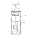
- FIG. 2 is a schematic sectional view showing an example of the internal structure of the X-ray tube 1.
- the X-ray tube 1 includes a tubular body portion 11 and a thin tubular portion 12 connected to the tubular body portion 11. Both the tubular body portion 11 and the thin tubular portion 12 are hollow tubes. The outer diameter of the thin tube portion 12 is smaller than that of the tubular body portion 11. Both ends of the tubular body 11 are sealed.
- a target 15 is provided at the tip portion 16 of the thin tube portion 12.
- the target 15 has a flat plate shape and is arranged at a position to close the tip of the thin tube portion 12.
- the end of the thin tube portion 12 is connected to one end of the tubular body portion 11.
- a ceramic connector 110 is arranged at the other end of the tubular body 11.
- the end of the thin tube portion 12 is open inside the tubular body portion 11. Therefore, the tubular body portion 11 and the thin tubular portion 12 communicate with each other, and the inside of the tubular body portion 11 and the inside of the thin tubular portion 12
- a filament 13 which is an electron generating portion is arranged inside the tube body portion 11.
- the filament 13 is made of, for example, tungsten.
- the filament 13 is heated by the electric power from the power supply unit 2 and is heated to emit thermoelectrons. In this way, the filament 13 generates electrons.
- the filament 13 is arranged at a position facing the opening 18 at the end of the thin tube portion 12.
- the thin tube portion 12 and the filament 13 are arranged so that the filament 13, the opening 18 at the end of the thin tube portion 12, and the target 15 are arranged substantially linearly.
- the X-ray tube 1 may have a form including an electron generation unit other than the filament 13.
- An electron accelerating unit 14 for accelerating the electrons generated from the filament 13 is arranged inside the tubular body 11.
- the electron acceleration unit 14 generates a voltage by the electric power from the power supply unit 2 and accelerates the electron by the voltage.
- the voltage generated between the filament 13 and the target 15 by the electron accelerating unit 14 is the acceleration voltage.
- the electrons generated from the filament 13 are accelerated by the acceleration voltage, enter the inside of the thin tube portion 12 through the opening 18, pass through the inside of the thin tube portion 12 along the longitudinal direction of the thin tube portion 12, and collide with the target 15. ..
- the X-ray tube 1 includes a magnetic field lens unit 17.
- the magnetic field lens unit 17 generates a magnetic field and focuses the moving electrons by the magnetic field.
- the magnetic field lens unit 17 is provided in the thin tube unit 12 and focuses the electrons passing through the thin tube unit 12.
- the magnetic field lens unit 17 focuses the electrons, so that more electrons collide with the target 15.
- the magnetic field lens unit 17 is configured by using, for example, a ring-shaped magnet.
- the magnetic field lens unit 17 may be configured to focus the electrons at one location along the longitudinal direction of the thin tube section 12, or may be configured to focus the electrons at a plurality of locations.
- the magnetic field lens unit 17 can be configured by using an electromagnet, it is preferably configured by using a permanent magnet.
- a power source for operating the electromagnet is required.
- heat is generated from the electromagnet, a heat exhausting mechanism is required.
- a permanent magnet is used, a power source and a heat exhaust mechanism are unnecessary, the structure of the X-ray tube 1 is simplified, and the X-ray tube 1 is downsized.
- the permanent magnet can be formed smaller than the electromagnet, the magnetic field lens unit 17 can be reduced in size and weight.
- the target 15 is made of a material that generates X-rays when an accelerated electron collides with it.
- the target 15 is formed using tungsten or molybdenum.
- X-rays generated by the accelerated electrons colliding with the target 15 pass through the target 15 and are emitted to the outside of the X-ray tube 1.
- the emitted X-rays are applied to the sample 5.
- Fluorescent X-rays are generated from the sample 5 by the irradiation of X-rays, the fluorescent X-rays are detected by the X-ray detector 3, and the analysis unit 43 performs elemental analysis.
- the inner diameter of the thin tube portion 12 is 3 mm or more. If the inner diameter of the thin tube portion 12 is 3 mm or more, a sufficient amount of electrons can pass through the inside of the thin tube portion 12.
- the distance from the tip of the filament 13 to the target 15 is more than three times the length of the outer diameter of the largest tubular portion 11 from the tip of the filament 13 to the target 15. Further, the outer diameter of the tip portion 16 of the thin tube portion 12 is 26 mm or less.
- the ceramic connector 110 seals the end of the tubular body 11.
- the ceramic connector 110 insulates the inside and outside of the tubular body 11 so that electrons generated in the tubular body 11 do not leak to the outside of the tubular body 11.
- the ceramic connector 110 needs to have a certain size in order to maintain insulation with respect to the power supply unit 2 that handles a high voltage. Therefore, there is a limit to reducing the outer diameter of the tubular body portion 11 in which the ceramic connector 110 is arranged. By increasing the distance from the filament 13 to the target 15, the outer diameter of the tip portion 16 of the thin tube portion 12 provided with the target 15 can be made significantly smaller than that of the tubular body portion 11.
- the target 15 can be brought closer to the sample 5 as compared with the case where the outer diameter of the tip portion 16 is larger. Further, since the target 15 is arranged at the tip portion 16 of the thin tube portion 12 connected to the tubular body portion 11, the large-sized tubular body portion 11 does not interfere with other components in the X-ray detection apparatus 10. , The target 15 can be brought as close as possible to the sample 5.
- the target 15 is an X-ray generation source, and by bringing the X-ray generation source closer to the sample 5, it becomes possible to irradiate the sample 5 with high-intensity X-rays. By irradiating the sample 5 with high-intensity X-rays, high-intensity fluorescent X-rays are generated, and high-precision elemental analysis can be performed using the high-intensity fluorescent X-rays.
- the acceleration voltage generated by the electron acceleration unit 14 is 21 kV or more and 70 kV or less.
- the acceleration voltage is preferably 40 kV or higher.
- the accelerating voltage exceeds 70 kV, the number of elements that can be subjected to elemental analysis hardly increases, so that the accelerating voltage up to 70 kV is sufficient.
- the thin tube portion 12 be made of a high thermal conductive material for heat dissipation.
- the high thermal conductive material is a material having a high thermal conductivity to the extent that the target 15 is not altered, melted or thermally decomposed by heat.
- the high thermal conductive material is copper. Since the thin tube portion 12 is made of a high thermal conductive material, the heat generated in the target 15 can be quickly dissipated. For example, the heat generated by the target 15 can be smoothly dissipated without using a large cooling mechanism such as a water cooling mechanism. Since the cooling mechanism is unnecessary, the tip portion 16 can be made thin.
- the outer surface of the thin tube portion 12 is preferably coated with a magnetic material by a method such as nickel plating. Even when the thin tube portion 12 is made of a material that does not exhibit ferromagnetism such as copper, the coated magnetic material serves as a magnetic shield, and an external magnetic field such as geomagnetism may enter the inside of the thin tube portion 12. There is no. Therefore, the trajectory of the electrons is not affected by the external magnetic field, and many electrons can efficiently collide with the target 15.
- FIG. 3 is a schematic cross-sectional view showing a configuration example of the tip portion 16 of the thin tube portion 12 according to the first embodiment.
- tip part 16 by the surface containing the central axis of the thin tube part 12 is shown.
- the central axis of the thin tube portion 12 is indicated by a chain line.
- the flat plate-shaped target 15 closes the tip of the thin tube portion 12.
- the inner surface of the tip portion 16 is tapered. That is, the inner diameter of the tip portion 16 continuously decreases toward the tip.
- a portion of the inner surface of the tip portion 16 where the inner diameter is continuously reduced is defined as a tapered surface 161.
- the inner diameter decreases linearly. That is, the tapered surface 161 is linearly inclined with respect to the surface of the target 15 within the plane including the central axis of the thin tube portion 12.
- the extended surface of the tapered surface 161 is indicated by a broken line.
- the spectrum of the generated fluorescent X-ray includes a peak that is not derived from the sample 5, a so-called system peak. Including the system peak in the spectrum of the fluorescent X-rays hinders the elemental analysis of the sample 5.
- the presence of the tapered surface 161 on the tip 16 limits the range in which the X-rays generated from the inner surface of the tip 16 are radiated.
- the X-rays generated from the tapered surface 161 are emitted to the inside of the thin tube portion 12 than the tapered surface 161, and are not emitted to the outside of the tapered surface 161. That is, in the plane including the central axis of the thin tube portion 12, X-rays are emitted only to the right side of the extension surface of the left tapered surface 161 shown in FIG. 3, and are not emitted to the left side of the extension surface. Similarly, X-rays are emitted only to the left side of the extension surface of the right tapered surface 161 shown in FIG.
- this region 162 it is possible to prevent the X-rays generated from the inner surface of the tip portion 16 from being detected by the X-ray detector 3. For example, by determining the position of the sample table 45 or the X-ray tube 1 so that the sample table 45 is located in the region 162, the X generated by the inner surface of the tip portion 16 and reflected by the sample 5 or the sample table 45 is reflected. The rays are prevented from entering the X-ray detector 3. This reduces the system peak and improves the accuracy of elemental analysis of the sample 5. Further, as the X-ray detector 3 is brought closer to the sample 5, the intensity of the fluorescent X-ray is improved, but the influence of the system peak may become more remarkable.
- the X-ray detector 3 is brought closer to the sample 5 to improve the intensity of the fluorescent X-rays, while suppressing the influence of the system peak, thereby reducing the elemental analysis of the sample 5.
- the accuracy can be improved.
- An angle 163 formed by the target 15 and the tapered surface 161 within the plane including the central axis of the thin tube portion 12 is an angle exceeding 90°.
- the angle 163 is preferably 120° or more.
- the inner diameter of the tip portion 16 may decrease non-linearly toward the tip.
- the angle of the tapered surface 161 with respect to the surface of the target 15 may be larger as the tip is closer.
- the configuration in which the inner diameter of the tip portion 16 decreases toward the tip is also applicable to X-ray tubes other than the X-ray tube in which the distance from the filament 13 to the target 15 is increased and the outer diameter of the tip portion 16 is decreased. ..
- it can be applied to an X-ray tube that does not require the target 15 to approach the sample 5.
- the X-rays generated from the inner surface of the tip portion 16 are suppressed from being detected by the X-ray detector 3, and the accuracy of elemental analysis of the sample 5 is improved.
- the X-ray detection device 10 may be configured to scan the sample 5 with X-rays.
- the X-ray detection apparatus 10 may scan the sample 5 with X-rays by sequentially moving the sample 5 or sequentially changing the X-ray direction.
- the X-ray detection device 10 sequentially detects fluorescent X-rays generated from a plurality of portions on the sample 5, and generates a distribution of elements contained in the sample 5 based on the detection result of the fluorescent X-rays. May be.
- the distance from the tip of the filament 13 to the target 15 is 2.5 times or more and 3 times or less as compared with the largest outer diameter of the tubular body portion 11 from the tip of the filament 13 to the target 15. It is also possible to adopt a configuration in which
- FIG. 4 is a schematic cross-sectional view showing a configuration example of the tip portion 16 of the thin tube portion 12 according to the second embodiment.
- tip part 16 by the surface containing the central axis of the thin tube part 12 is shown.
- the central axis of the thin tube portion 12 is shown by a chain line.
- the target 15 has a flat plate shape and closes the tip of the thin tube portion 12.
- the surface of the target 15 is not orthogonal to the central axis of the thin tube portion 12 but is inclined.
- the accelerated electrons collide with the target 15, and the generated X-rays pass through the target 15 and are emitted to the outside of the X-ray tube 1.
- the configurations of the other portions of the X-ray tube 1 and the portions of the X-ray detection apparatus 10 other than the X-ray tube 1 are the same as those in the first embodiment.
- arrows indicate the directions in which X-rays are emitted.
- the X-rays are emitted in a direction orthogonal to the surface of the target 15. More specifically, the X-rays are radiated radially centered on the direction orthogonal to the surface of the target 15. Since the surface of the target 15 is inclined with respect to the central axis of the thin tube section 12, X-rays are emitted in a direction intersecting with the central axis of the thin tube section 12.
- the outer diameter of the tip portion 16 of the thin tube portion 12 provided with the target 15 can be made significantly smaller than that of the tubular body portion 11.
- the small outer diameter of the tip 16 allows the target 15 to approach the sample 5.
- the target 15 can be brought close to the sample 5 without the tubular body portion 11 interfering with other components in the X-ray detection apparatus 10.
- the target 15 can be brought closer to the sample 5 depending on the structure of the X-ray detection device 10.
- FIG. 5 is a schematic cross-sectional view showing a configuration example of the tip end portion 16 of the thin tube portion 12 according to the third embodiment.
- tip part 16 by the surface containing the central axis of the thin tube part 12 is shown.
- the tip of the thin tube portion 12 is sealed.
- the target 15 has a flat plate shape and is arranged inside the tip portion 16 (in the cavity included in the tip portion 16).
- a window 164 through which X-rays can pass is provided on the side of the tip portion 16.
- electrons are indicated by dashed arrows and X-rays are indicated by straight arrows.
- the configurations of the other portions of the X-ray tube 1 and the portions of the X-ray detection apparatus 10 other than the X-ray tube 1 are the same as those in the first embodiment.
- the outer diameter of the tip portion 16 of the thin tube portion 12 provided with the target 15 can be made significantly smaller than that of the tubular body portion 11. Since the outer diameter of the tip portion 16 is small, the target 15 can be brought closer to the sample 5. Further, the target 15 can be brought as close as possible to the sample 5 without the tubular body portion 11 interfering with other components in the X-ray detection device 10.
- high-intensity fluorescent X-rays are generated, and high-precision elemental analysis can be performed using the high-intensity fluorescent X-rays.
- FIG. 6 is a schematic plan view showing a first example of the target 15 according to the fourth embodiment.
- the target 15 has a flat plate shape and includes a plurality of collision regions 151 to which electrons should collide.
- the plurality of collision regions 151 have different compositions.
- the plurality of collision areas 151 are made of different kinds of elements. Since the plurality of collision regions 151 have different compositions, the energy of the electrons generated when the electrons collide with the collision region 151 differs depending on the collision region 151.
- FIG. 6 shows an example in which the target 15 has two collision regions 151, the target 15 may have three or more collision regions 151.
- FIG. 7 is a schematic plan view showing a second example of the target 15 according to the fourth embodiment.
- a collided body 153 to which electrons should collide is provided on the surface of the target 15.
- FIG. 8 is a schematic perspective view showing the collision object 153.
- the collision object 153 is a polyhedron and has a plurality of collision surfaces 152.
- the collided body 153 is arranged at a position where electrons collide with the collision surface 152.
- the plurality of collision surfaces 152 have different compositions.
- the plurality of collision surfaces 152 are made of different kinds of elements. Since the plurality of collision surfaces 152 have different compositions, the energy of electrons generated when electrons collide with the collision surfaces 152 differs depending on the collision surfaces 152.
- FIG. 7 shows an example in which the collided body 153 has four collision surfaces 152, but the collided body 153 may have three collision surfaces 152, and five or more collision surfaces 152. May have.
- the magnetic field lens unit 17 can change the course of accelerated electrons.
- the magnetic field lens unit 17 is configured by using a plurality of electromagnets, and the control unit 41 controls which electromagnet is operated.
- the magnetic field lens unit 17 focuses electrons and adjusts the paths of the electrons, and selects which collision region 151 or collision surface 152 the electrons collide with.
- the magnetic field lens unit 17 may be configured by using a permanent magnet.
- 9A and 9B are schematic cross-sectional views showing the magnetic field lens unit 17 according to the fourth embodiment using a permanent magnet.
- disconnected the magnetic field lens part 17 and the thin tube part 12 in the surface which intersects the central axis of the thin tube part 12 is shown.
- the magnetic field lens section 17 is arranged outside the thin tube section 12, and two permanent magnets are arranged so as to sandwich the thin tube section 12 from both sides. Further, the magnetic field lens unit 17 is configured so that the position of the permanent magnet can be changed.
- FIG. 9A shows a state in which two permanent magnets are arranged in the horizontal direction in the figure, and FIG.
- the magnetic field lens unit 17 may use a single permanent magnet, or may use three or more permanent magnets. Further, the magnetic field lens unit 17 may adjust the path of the electrons by changing the position of the permanent magnet in the longitudinal direction of the thin tube unit 12.
- the magnetic field lens unit 17 may be configured so that the position of the permanent magnet can be changed manually. When the magnetic field lens section 17 is arranged outside the thin tube section 12, at least a portion of the outer surface of the thin tube section 12 where the magnetic field lens section 17 is arranged is not coated with a magnetic material.
- the configuration of the other parts of the X-ray tube 1 and the configuration of the parts of the X-ray detection apparatus 10 other than the X-ray tube 1 are the same as in any of the first to third embodiments.
- the X-ray tube 1 can change the collision area 151 or the collision surface 152 where electrons collide.
- the energy of the X-rays emitted by the X-ray tube 1 is changed by changing the collision area 151 or the collision surface 152 where the electrons collide.
- FIG. 10 is a block diagram showing the configuration of the X-ray detection apparatus 10 according to the fifth embodiment.
- the configuration of the X-ray tube 1 is the same as in any of the first to fourth embodiments.
- the position of the X-ray tube 1 with respect to the X-ray detector 3 can be changed, and the tip of the thin tube portion 12 is brought close to the sample 5.
- the X-ray detection device 10 includes a power supply unit 2, an X-ray detector 3, a control unit 41, a signal processing unit 42, an analysis unit 43, and a display unit 44.
- the X-ray tube 1 and the power supply unit 2 may be separated from the X-ray detector 3, the control unit 41, the signal processing unit 42, the analysis unit 43, and the display unit 44. In this case, the X-ray tube 1 and the power supply unit 2 are controlled by a control unit different from the control unit 41.
- the X-ray detection device 10 is, for example, a mobile type X-ray detection device 10.
- the sample 5 such as a cultural property may have a complicated shape.
- the sample 5 is a pipe or a pot.
- the X-ray tube 1 has a thin tube portion 12 having an outer diameter smaller than that of the tube body portion 11, and a target 15 is provided at a tip portion 16 of the thin tube portion 12.
- the tubular body portion 11 thicker than the thin tubular portion 12 collides with the sample 5 and the sample 5 It may be difficult to bring the target 15 close to a desired portion. In this case, it becomes difficult to irradiate the desired portion of the sample 5 with X-rays, and it becomes difficult to analyze the desired portion of the sample 5.
- the thin tubular portion 12 has a length such that the distance from the filament 13 to the target 15 exceeds three times. It's getting longer. Since the thin tube portion 12 is elongated, as shown in FIG. 10, it is possible to insert the thin tube portion 12 into the sample 5 having a complicated shape and bring the target 15 close to a desired portion of the sample 5. Therefore, even when the sample 5 has a complicated shape, it is possible to irradiate a desired portion of the sample 5 with X-rays from the X-ray tube 1. Fluorescent X-rays are generated from the sample 5 irradiated with X-rays, the X-ray detector 3 detects the fluorescent X-rays, and a desired portion of the sample 5 is analyzed.
- the target 15 can be brought close to a desired portion of the sample 5 even if the sample 5 has a complicated shape.
- high-intensity fluorescent X-rays are generated, and high-precision elemental analysis can be performed using the high-intensity fluorescent X-rays.
- the sample 5 can be analyzed nondestructively.
- the mobile X-ray detection apparatus 10 may have a form in which the target 15 includes a plurality of collision areas 151, as in the fourth embodiment. It is assumed that the mobile type X-ray detection device 10 is used for measuring various types of samples 5 at the site where the samples 5 such as cultural properties exist. By changing the collision area 151 to be used according to the type of the sample 5, it becomes possible to use X-rays having an appropriate energy for the elements contained in the sample 5. Therefore, it is possible to perform an appropriate analysis on various samples 5 in the field.
- FIG. 11 is a schematic diagram showing the X-ray tube 1 according to the sixth embodiment.
- the thin tube portion 12 has flexibility and can have not only a linear shape but also a curved shape.
- the thin tube portion 12 is configured by using a flexible tube.
- the flexible tube is configured by using a spiral tube formed by spirally winding a band-shaped metal and a resin that covers the spiral tube.
- the magnetic field lens unit 17 is configured to adjust the course of the electrons so that the electrons can pass through the curved thin tube unit 12.
- the magnetic field lens unit 17 has magnets arranged at a plurality of locations along the longitudinal direction of the thin tube unit 12, and guides electrons to the target 15 even when the thin tube unit 12 has a curved shape. It has become.
- the magnetic field lens unit 17 is capable of changing the course of accelerated electrons, as in the fourth embodiment, and the electrons pass through the curved thin tube unit 12 to the target 15.
- the target 15 can be brought closer to a desired portion of the sample 5 by forming the thin tube portion 12 into a curved shape.
- high-intensity fluorescent X-rays are generated, and high-precision elemental analysis can be performed using the high-intensity fluorescent X-rays.
- the sample 5 can be analyzed nondestructively.
- FIG. 12 is a block diagram showing the X-ray tube 1 according to the seventh embodiment.
- the X-ray tube 1 has a sealing valve 19 that seals the tubular body portion 11 and the thin tubular portion 12 in order to keep the insides of the tubular body portion 11 and the thin tubular portion 12 in a depressurized state.
- the power supply unit 2 has a power storage unit 21 using a secondary battery. The power supply unit 2 uses the power stored in the power storage unit 21 to supply power to the X-ray tube 1.
- the detachable unit 6 can be attached to and detached from the tubular body 11.
- the attachment/detachment unit 6 has a pressure reducing portion 61 that is connected to the sealing valve 19 when attached.
- the decompression unit 61 includes a vacuum pump, and can decompress the inside of the tubular body portion 11 and the thin tubular portion 12.
- the sealing valve 19 is opened, and the depressurizing portion 61 communicates with the insides of the tubular body portion 11 and the thin tubular portion 12 via the sealing valve 19.
- the decompression section 61 operates to decompress the inside of the tubular body section 11 and the thin tube section 12.
- the sealing valve 19 is closed and the attachment/detachment unit 6 is detached in a state where the insides of the tubular body portion 11 and the thin tubular portion 12 are sufficiently decompressed.
- the X-ray tube 1 operates with the detachable unit 6 detached.
- the detachable unit 6 has a power supply unit 62 that supplies power to the power storage unit 21 when mounted.
- the power feeding portion 62 is connected to the power source portion 2.
- Power supply unit 62 supplies power to power storage unit 21, and power storage unit 21 is charged.
- the power supply unit 2 operates with the detachable unit 6 detached.
- the configuration of the other portions of the X-ray tube 1 is the same as in any of the first to sixth embodiments, and the configuration of the portions of the X-ray detection device 10 other than the X-ray tube 1 and the power supply unit 2 is the same as in the fifth or sixth embodiment. Is.
- the X-ray tube 1 can reduce the pressure inside the tubular body portion 11 and the thin tube portion 12 by the detachable unit 6, so it is not necessary to maintain the reduced pressure state for a long time. Therefore, the structure of the X-ray tube 1 can be a simple structure that can maintain a decompressed state for a short period of time.
- the structure of the sealing valve 19 can also be a simple structure that can maintain the depressurized state for a short period of time. Therefore, the weight and cost of the X-ray tube 1 can be reduced.
- the power supply unit 2 can use the power storage unit 21 by enabling the detachable unit 6 to supply power.
- the X-ray tube 1 can be used even when there is no external power supply. Therefore, the X-ray tube 1 and the X-ray detection device 10 can be mobile type. By making the X-ray tube 1 or the X-ray detection device 10 a mobile type, the X-ray tube 1 can be brought as close as possible to the sample 5. Further, the detachable unit 6 can simultaneously reduce the pressure inside the tubular body portion 11 and the thin tubular portion 12 and supply power to the power storage unit 21. Therefore, the work for making the X-ray tube 1 operable can be completed in a short time.
- the X-ray tube 1 and the X-ray detector 3 are separated from each other.
- the sample 5 has a complicated shape, it may be difficult to bring both the X-ray tube 1 and the X-ray detector 3 close to the sample 5.
- the eighth embodiment shows a form in which the X-ray tube 1 and the X-ray detector 3 are integrated.
- FIG. 13 is a block diagram showing the configuration of the X-ray detection apparatus 10 according to the eighth embodiment.
- the X-ray tube 1 includes a tube body part 11.
- a filament 13, which is an electron generating portion, an electron accelerating portion 14, a target 15, and an X-ray detector 3 are arranged in the tubular body portion 11.
- a power supply unit 2 is connected to the X-ray tube 1.
- the power supply unit 2 supplies electric power to the X-ray tube 1.
- a signal processing unit 42 is connected to the X-ray tube 1.
- the filament 13 generates electrons, and the electron acceleration unit 14 accelerates the electrons.
- the accelerated electrons collide with the target 15 and X-rays are generated from the target 15.
- FIG. 14 is a schematic cross-sectional view showing a part of the X-ray tube 1 according to the eighth embodiment.
- the tubular body portion 11 has an X-ray transmission portion 111.
- a part of the tubular body portion 11 is made of a substance that transmits X-rays, and serves as an X-ray transmission portion 111.
- the X-ray transmission part 111 is made of beryllium.
- the X-ray transmission part 111 is provided on the side part of the tubular body part 11.
- the X-ray generated from the target 15 is transmitted through the X-ray transmission unit 111, radiated to the outside of the X-ray tube 1, and irradiated on the sample 5.
- the trajectory of electrons that collide with the target 15 is indicated by a dashed-dotted line, and the X-ray generated from the target 15 is indicated by a solid arrow.
- the X-ray detector 3 is arranged at a position between the target 15 and the X-ray transmission unit 111.
- the X-ray detector 3 is plate-shaped and has a through hole 34 formed therein.
- the X-ray detector 3 is arranged at a position where the optical axis of the X-ray generated from the target 15 passes through the through hole 34.
- the X-rays generated from the target 15 pass through the through holes 34, pass through the X-ray transmitting portion 111, and are irradiated to the sample 5 outside the X-ray tube 1.
- Fluorescent X-rays are generated in the sample 5 irradiated with X-rays.
- the fluorescent X-rays are indicated by broken line arrows.
- the X-ray detector 3 has a radiation detection element 31, a cooling unit 32, and a shield unit 33.
- the radiation detection element 31 is a semiconductor element that detects radiation, and is, for example, an SDD (Silicon Drift Detector).
- the radiation detection element 31 may be an element other than SDD.
- the cooling unit 32 is an element that cools the radiation detection element 31, and is, for example, a Peltier element.
- the shield part 33 prevents the X-rays from the target 15 from entering the radiation detection element 31.
- the shield part 33 is arranged at a position facing the target 15, and the radiation detecting element 31 is arranged at a position facing the X-ray transmitting part 111.
- the X-ray detector 3 is arranged at a position where the X-rays from the outside that have passed through the X-ray transmission unit 111 are incident on the radiation detection element 31.
- the fluorescent X-rays generated in the sample 5 pass through the X-ray transmission unit 111 and enter the radiation detection element 31.
- the X-ray detector 3 detects the incident fluorescent X-ray.
- a signal processing unit 42 is connected to the X-ray tube 1.
- the signal processing unit 42 is connected to the X-ray detector 3 in the X-ray tube 1.
- the signal processing unit 42 receives the signal output by the X-ray detector 3 and generates a spectrum of the fluorescent X-ray detected by the signal processing unit 42.
- the signal processing unit 42 is connected to the analysis unit 43.
- the analysis unit 43 performs elemental analysis of the sample 5 based on the spectrum of the fluorescent X-ray.
- a display unit 44 is connected to the analysis unit 43.
- the signal processing unit 42, the analysis unit 43, and the power supply unit 2 are connected to the control unit 41.
- FIG. 15 is a plan view schematically showing an example of the X-ray detector 3 according to the eighth embodiment.
- the radiation detection element 31 has an annular shape and has a through hole 34 formed therein.
- the X-ray detector 3 is arranged so that the optical axis 35 of the X-ray generated from the target 15 passes through the through hole 34.
- the X-ray detector 3 having such a configuration, the X-rays from the target 15 are radiated to the outside of the X-ray tube 1, and the fluorescent X-rays from the outside that have passed through the X-ray transmission unit 111 are efficiently emitted. It can be detected by the X-ray detector 3.
- the radiation detection element 31 may have a rectangular ring shape such as an octagonal ring. Further, the radiation detection element 31 may have a shape in which a part of the ring is not connected.
- FIG. 16 is a plan view schematically showing another example of the X-ray detector 3 according to the eighth embodiment.
- the X-ray detector 3 has a plurality of radiation detection elements 31.
- the X-ray detector 3 does not have to be integrated.
- the plurality of radiation detection elements 31 are arranged around the optical axis 35 of the X-ray generated from the target 15. Also in this example, the X-rays from the target 15 are radiated to the outside of the X-ray tube 1, and the fluorescent X-rays from the outside that have passed through the X-ray transmission unit 111 can be efficiently detected by the X-ray detector 3. it can.
- the number of the radiation detection elements 31 is four is shown in FIG. 16, the number of the radiation detection elements 31 may be other than four.
- the shape of the radiation detection element 31 is rectangular is shown in FIG. 16, the shape of the radiation detection element 31 may be a shape other than a rectangle, such as a circle.
- the X-ray tube 1 can approach a sample 5 such as a pipe having a complicated shape.
- the X-ray transmission part 111 can be brought close to a desired part of the sample 5. Therefore, both the target 15 and the X-ray detector 3 can be brought close to the desired portion of the sample 5.
- the sample 5 has a complicated shape, it is difficult to bring both the X-ray tube 1 and the X-ray detector 3 close to the sample 5.
- the eighth embodiment it is possible to bring both the X-ray generation source and the fluorescent X-ray detection unit closer to the sample 5 by merely bringing only the X-ray tube 1 closer to the sample 5.
- the sample 5 is irradiated with high-intensity X-rays, high-intensity fluorescent X-rays are generated, and the high-intensity fluorescent X-rays can be efficiently detected. Therefore, highly accurate elemental analysis is possible. Further, since it is possible to efficiently detect high-intensity fluorescent X-rays and perform elemental analysis, it is possible to increase the response speed of elemental analysis while maintaining high accuracy. As described above, even when the sample 5 has a complicated shape, it is possible to perform element analysis with high accuracy and high speed response. Further, the sample 5 can be analyzed nondestructively.
- FIG. 17 is a schematic sectional view showing the internal structure of the X-ray tube 1 according to the ninth embodiment.
- a part of the tip portion of the tubular body portion 11 is opened, and the target 15 is arranged by closing the opened portion.
- the target 15 has a flat plate shape and is fitted into the open portion of the tubular body 11.
- An X-ray transmission unit 111 is arranged around the target 15.
- the X-ray transmission part 111 forms a part of the tip portion of the tubular body part 11.
- a filament 13, which is an electron generating portion, an electron accelerating portion 14, and an X-ray detector 3 are arranged in the tubular body portion 11.
- the X-ray detector 3 is arranged near the X-ray transmission unit 111.
- the X-ray detector 3 is plate-shaped and has a through hole 34 formed therein.
- the X-ray detector 3 is arranged at a position such that the optical axis of the electron colliding with the target 15 passes through the through hole 34.
- the electrons generated from the filament 13 are accelerated by the electron acceleration unit 14, pass through the through hole 34, and collide with the target 15.
- X-rays are generated from the target 15 due to the collision of electrons, and the generated X-rays pass through the target 15 and are radiated to the outside of the X-ray tube 1 and irradiated on the sample 5.
- the trajectory of the electrons colliding with the target 15 is shown by the alternate long and short dash line, and the X-ray generated from the target 15 is shown by the solid arrow.
- Fluorescent X-rays are generated in the sample 5 irradiated with X-rays.
- the fluorescent X-rays pass through the X-ray transmitting unit 111 and enter the X-ray detector 3.
- the X-ray detector 3 detects the incident fluorescent X-ray.
- fluorescent X-rays are indicated by broken line arrows.
- the configuration of the X-ray detection apparatus 10 other than the X-ray tube 1 is the same as that of the eighth embodiment.
- the X-ray tube 1 can approach the sample 5 having a complicated shape.
- both the target 15 and the X-ray detector 3 can be brought closer to the desired portion of the sample 5.
- the sample 5 is irradiated with high-intensity X-rays, high-intensity fluorescent X-rays are generated, high-intensity fluorescent X-rays can be efficiently detected, and high-precision elemental analysis becomes possible.
- the sample 5 has a complicated shape, it is possible to perform highly accurate elemental analysis. Further, it becomes possible to analyze the sample 5 nondestructively.
- the X-ray detector 3 may have a plurality of radiation detection elements 31, and the plurality of radiation detection elements 31 may be arranged around the optical axis of the electron that collides with the target 15. Also in this form, the electrons collide with the target 15, the X-rays from the target 15 are radiated to the outside of the X-ray tube 1, and the fluorescent X-rays from the outside that have passed through the X-ray transmission unit 111 are detected by the X-ray detector 3. Can be detected with.
- the energy dispersive type in which X-rays are separated by energy and detected is shown.
- the X-ray detection apparatus 10 has a wavelength in which X-rays are separated by wavelength and detected. It may be in a dispersed form.
- the mode in which fluorescent X-rays are detected has been described, but the X-ray detection apparatus 10 may be in a mode in which X-rays other than fluorescent X-rays are detected.
- the X-ray detection device 10 may be in a form of detecting transmitted X-rays that have passed through the sample 5 or diffracted X-rays.
- an X-ray tube including an electron generating unit, a target that generates X-rays by collision of electrons generated by the electron generating unit, and a tube body section in which the electron generating unit and the target are arranged.
- An X-ray detector disposed inside the tubular body, The tubular body portion has an X-ray transmission portion that transmits X-rays, An X-ray tube, wherein the X-ray detector is arranged at a position where X-rays from the outside that have passed through the X-ray transmission unit are incident.
- the X-ray detector is plate-shaped, has a through hole, and is arranged at a position where an optical axis of X-rays generated from the target passes through the through hole.
- X-ray tube according to.
- the X-ray detector has a plurality of X-ray detection elements, The X-ray tube according to appendix 1, wherein the plurality of X-ray detection elements are arranged around an optical axis of X-rays generated from the target.
- X-rays generated from the target are radiated to the outside through the X-ray transmission unit,
- the X-ray detector detects X-rays generated from a sample irradiated to the outside and irradiated with X-rays and transmitted through the X-ray transmission unit.
- the X-ray tube described.
- the target is arranged at a position to close the open portion of the tubular body,
- the X-ray transmission unit is arranged around the target,
- the X-ray detector is plate-shaped, has a through hole, and is arranged at a position where an optical axis of an electron colliding with the target passes through the through hole.
- the X-ray tube described.
- An X-ray detection device comprising: an analysis unit that performs elemental analysis based on a detection result of an X-ray detector included in the X-ray tube.
Abstract
Provided are an X-ray tube and an X-ray detector that can bring a target as close as possible to a sample. The X-ray tube comprises: an electron generation unit; an electron acceleration unit that accelerates electrons generated by the electron generation unit with a voltage; a target with which the accelerated electrons collide so that X-rays are generated; a tubular body part in which the electron generation unit is disposed; a narrow-tube part which has a smaller outer diameter than the tubular body part and communicates with the tubular body part, and through which the accelerated electrons pass the inside thereof along a longitudinal direction; and a magnetic field lens part that focuses the electrons passing through the inside of the narrow-tube part by means of a magnetic field, wherein the target is disposed at a tip portion of the narrow-tube part, and the distance from the electron generation unit to the target along the longitudinal direction of the narrow-tube part exceeds three times the largest outer diameter of the tubular body part from the electron generation unit to the target along the longitudinal direction of the narrow-tube part.
Description
本発明は、X線を発生させるX線管、及びX線検出装置に関する。
The present invention relates to an X-ray tube that generates X-rays and an X-ray detection device.
試料へX線を照射し、試料を透過したX線、又は試料から発生した二次X線を検出し、試料の分析を行うことができる。例えば、試料から発生した蛍光X線に基づいて元素を分析する蛍光X線分析を行うことができる。このような分析に用いられるX線を発生させるために、X線管が用いられている。X線管では、加熱されたフィラメント等の電子発生部から電子を発生させ、電界により電子を加速し、加速した電子をターゲットに衝突させ、ターゲットからX線を発生させる。特許文献1には、X線管の例が記載されている。
-A sample can be analyzed by irradiating it with X-rays and detecting X-rays that have passed through the sample or secondary X-rays generated from the sample. For example, fluorescent X-ray analysis for analyzing an element can be performed based on the fluorescent X-ray generated from the sample. X-ray tubes are used to generate X-rays used for such analysis. In an X-ray tube, electrons are generated from an electron generation unit such as a heated filament, the electrons are accelerated by an electric field, the accelerated electrons collide with a target, and X-rays are generated from the target. Patent Document 1 describes an example of an X-ray tube.
X線を利用した分析を高精度に行うためには、高強度のX線を試料へ照射することが望ましい。高強度のX線を試料へ照射するためには、X線の発生源を試料へ近づけることが望ましい。しかしながら、X線管の大きさのため、X線管のターゲットを試料に近づけることには限界がある。
In order to carry out analysis using X-rays with high precision, it is desirable to irradiate the sample with high-intensity X-rays. In order to irradiate the sample with high-intensity X-rays, it is desirable to bring the X-ray generation source closer to the sample. However, due to the size of the X-ray tube, there is a limit to bringing the target of the X-ray tube close to the sample.
本発明は、斯かる事情に鑑みてなされたものであって、その目的とするところは、可及的に試料へターゲットを近づけることができるX線管及びX線検出装置を提供することにある。
The present invention has been made in view of such circumstances, and an object of the present invention is to provide an X-ray tube and an X-ray detection device that can bring a target as close to a sample as possible. ..
本発明に係るX線管は、電子発生部と、前記電子発生部が発生させた電子を電圧によって加速させる電子加速部と、加速された電子が衝突することによってX線を発生させるターゲットとを備えるX線管において、内部に前記電子発生部が配置された管体部と、前記管体部よりも外径が小さい管状であり、前記管体部に連通しており、前記加速された電子が内部を長手方向に沿って通過する細管部と、前記細管部の内部を通過する電子を磁界によって集束させる磁界レンズ部とを備え、前記ターゲットは、前記細管部の先端部に配置されており、前記細管部の長手方向に沿って前記電子発生部から前記ターゲットまでの間で最も大きい前記管体部の外径に比べて、前記細管部の長手方向に沿って前記電子発生部から前記ターゲットまでの距離は三倍を超過する長さであることを特徴とする。
An X-ray tube according to the present invention includes an electron generating unit, an electron accelerating unit that accelerates electrons generated by the electron generating unit by a voltage, and a target that generates X-rays when the accelerated electrons collide. In an X-ray tube provided, a tubular body portion in which the electron generating portion is disposed, and a tubular body having an outer diameter smaller than that of the tubular body portion, the tubular body portion communicating with the tubular body portion, and the accelerated electron Is provided with a thin tube portion that passes through the inside along the longitudinal direction, and a magnetic field lens portion that focuses the electrons that pass through the inside of the thin tube portion by a magnetic field, and the target is arranged at the tip portion of the thin tube portion. The target from the electron generating portion along the longitudinal direction of the thin tube portion as compared with the outer diameter of the tubular body portion which is the largest between the electron generating portion and the target along the longitudinal direction of the thin tube portion. The distance to is more than triple the length.
本発明においては、X線管は、電子発生部が配置された管体部と、より外径が小さい細管部とを備え、ターゲットは細管部の先端部にあり、電子発生部からターゲットまでの距離は管体部の外径に比べて三倍を超過する長さである。外径が小さい細管部の先端部にターゲットを配置することにより、ターゲットを試料へ近づけることができる。電子発生部からターゲットまでの距離を長くすることにより、サイズの大きい管体部が他の機器に干渉すること無く、ターゲットを試料へ可及的に近づけることができる。
In the present invention, the X-ray tube includes a tubular body portion in which the electron generating portion is arranged and a thin tube portion having a smaller outer diameter, and the target is at the tip of the thin tube portion, and the target from the electron generating portion to the target. The distance is more than three times the length of the outer diameter of the tubular body. The target can be brought closer to the sample by disposing the target at the tip of the thin tube portion having a small outer diameter. By increasing the distance from the electron generating unit to the target, the target can be brought as close as possible to the sample without the large-sized tube portion interfering with other devices.
本発明に係るX線管は、電子を加速させるために前記電子加速部が発生させる電圧は21kV以上70kV以下であることを特徴とする。
The X-ray tube according to the present invention is characterized in that the voltage generated by the electron acceleration unit for accelerating electrons is 21 kV or more and 70 kV or less.
本発明においては、電子を加速させる電圧は21kV以上70kV以下である。これにより、試料に含まれ分析対象となり得るほぼ全ての元素について十分な精度で元素分析を行うための蛍光X線を試料から発生させることができる。
In the present invention, the voltage for accelerating electrons is 21 kV or more and 70 kV or less. As a result, it is possible to generate from the sample fluorescent X-rays for performing elemental analysis with sufficient accuracy for almost all the elements contained in the sample that can be analyzed.
本発明に係るX線管は、前記細管部は、高熱伝導材を用いて構成されており、前記細管部の外面は磁性材でコーティングされていることを特徴とする。
The X-ray tube according to the present invention is characterized in that the thin tube portion is made of a high thermal conductive material, and the outer surface of the thin tube portion is coated with a magnetic material.
本発明においては、細管部は高熱伝導材を用いて構成されており、効率良くターゲットからの熱が放熱される。また、細管部の外面は磁性材でコーティングされている。コーティングされた磁性材が磁気シールドとなり、外部磁界によって電子の進路が影響を受けることが無い。
In the present invention, the thin tube portion is made of a high thermal conductive material, and the heat from the target is efficiently radiated. Further, the outer surface of the thin tube portion is coated with a magnetic material. The coated magnetic material serves as a magnetic shield, and the course of the electrons is not affected by the external magnetic field.
本発明に係るX線管は、前記磁界レンズ部は、永久磁石を用いて構成されていることを特徴とする。
The X-ray tube according to the present invention is characterized in that the magnetic field lens section is configured by using a permanent magnet.
本発明においては、加速させた電子を集束する磁界レンズ部は、永久磁石を用いて構成されている。永久磁石を用いることにより、磁界レンズ部が小型化・軽量化する。また、電磁石を使用するために必要な機構が不要となり、X線管の構造が簡素化する。
In the present invention, the magnetic field lens unit that focuses the accelerated electrons is configured by using a permanent magnet. By using a permanent magnet, the magnetic field lens unit can be made smaller and lighter. Moreover, the mechanism required for using the electromagnet is not required, and the structure of the X-ray tube is simplified.
本発明に係るX線管は、前記ターゲットは、組成の異なる複数の領域を有し、前記磁界レンズ部は、前記複数の領域の内で前記加速された電子が衝突する領域を変更することを特徴とする。
In the X-ray tube according to the present invention, the target has a plurality of regions having different compositions, and the magnetic field lens unit changes a region in which the accelerated electrons collide in the plurality of regions. Characterize.
本発明においては、ターゲットは組成の異なる複数の領域を有し、X線管は電子が衝突する領域が変更可能になっている。電子が衝突する領域を変更することによって、X線管が放射するX線のエネルギーが変更され、試料の種類に応じて適切なエネルギーのX線を利用することが可能となる。
In the present invention, the target has a plurality of regions having different compositions, and the X-ray tube can change the region where electrons collide. The energy of the X-rays emitted by the X-ray tube is changed by changing the region where the electrons collide, and it becomes possible to use the X-rays having the appropriate energy according to the type of the sample.
本発明に係るX線管は、前記ターゲットは、前記細管部の先端を塞ぐ位置に配置されてあり、前記X線は、前記ターゲットを通過して外部へ放射され、前記先端部の内径は、前記先端にかけて連続的に減少していることを特徴とする。
In the X-ray tube according to the present invention, the target is arranged at a position that closes the tip of the thin tube portion, the X-ray is radiated to the outside through the target, and the inner diameter of the tip portion is It is characterized in that it continuously decreases toward the tip.
本発明においては、ターゲットは細管部の先端を塞いでおり、X線はターゲットを通過してX線管の外部へ放射される。細管部の先端部の内径は、先端にかけて連続的に減少している。細管部の先端の正面には、電子が衝突した先端部の内面から発生した蛍光X線が放出されない領域が存在する。先端部の内面から発生した蛍光X線が検出されることが抑制され、試料からのX線を測定する際のシステムピークが減少する。
In the present invention, the target blocks the tip of the thin tube portion, and X-rays pass through the target and are emitted to the outside of the X-ray tube. The inner diameter of the tip portion of the thin tube portion continuously decreases toward the tip. On the front surface of the tip of the thin tube portion, there is a region where the fluorescent X-ray generated from the inner surface of the tip portion where the electron collides is not emitted. Detection of fluorescent X-rays generated from the inner surface of the tip is suppressed, and the system peak when measuring X-rays from the sample is reduced.
本発明に係るX線管は、前記細管部は、可撓性を有していることを特徴とする。
The X-ray tube according to the present invention is characterized in that the thin tube portion has flexibility.
本発明においては、細管部は可撓性を有している。細管部を曲線状にすることが可能となり、曲線状の細管部を用いて試料の所望の部分にターゲットをより近づけることが可能となる。
In the present invention, the thin tube portion has flexibility. It becomes possible to make the thin tube portion curved, and the curved thin tube portion can be used to bring the target closer to the desired portion of the sample.
本発明においては、前記先端部の外径は26mm以下であることを特徴とする。
In the present invention, the outer diameter of the tip portion is 26 mm or less.
本発明においては、細管部の先端部の外径が26mm以下であり、細管部が十分に細いので、試料が入り組んだ形状を有している場合であっても、試料の所望の部分にターゲットを近づけることが可能となる。
In the present invention, the outer diameter of the tip of the thin tube portion is 26 mm or less, and the thin tube portion is sufficiently thin, so that even if the sample has an intricate shape, the target can be targeted to a desired portion of the sample. Can be brought closer.
本発明に係るX線管は、前記電子発生部及び前記電子加速部を稼働させるための電力を蓄電する蓄電部と、前記管体部に着脱可能であり、前記管体部に装着されている場合に、前記管体部及び前記細管部の内部を減圧し、前記蓄電部に給電する着脱ユニットと、前記着脱ユニットが前記管体部から離脱している場合に、前記管体部及び前記細管部の内部が減圧された状態を維持するべく、前記管体部及び前記細管部を封止する封止弁とを更に備えることを特徴とする。
The X-ray tube according to the present invention is attachable to and detachable from a power storage unit that stores electric power for operating the electron generation unit and the electron acceleration unit, and is attached to the pipe body unit. In this case, the detachable unit that decompresses the inside of the tubular body portion and the thin tubular portion and supplies power to the power storage unit, and the tubular body portion and the thin tubular portion when the detachable unit is detached from the tubular body portion A sealing valve for sealing the tubular body portion and the thin tubular portion is further provided so as to maintain a reduced pressure inside the portion.
本発明においては、管体部に着脱可能な着脱ユニットは、管体部及び細管部の内部を減圧し、X線管を稼働させるための電力を蓄電する蓄電部に給電する。管体部及び細管部の内部を着脱ユニットによって減圧することができるので、X線管の構造を、一時的に減圧状態を保つことが可能な程度の簡素な構造とすることができる。着脱ユニットが給電を可能とすることによって、蓄電部を用いることが可能となり、外部からの電力の供給が無い状態でもX線管を使用することができる。
In the present invention, the detachable unit that can be attached to and detached from the tube body depressurizes the insides of the tube body and the thin tube section, and supplies power to the power storage section that stores power for operating the X-ray tube. Since the insides of the tubular body portion and the thin tubular portion can be decompressed by the detachable unit, the structure of the X-ray tube can be a simple structure capable of temporarily maintaining a decompressed state. By enabling the detachable unit to supply power, the power storage unit can be used, and the X-ray tube can be used even when no external power is supplied.
本発明に係るX線検出装置は、本発明に係るX線管と、該X線管から放射されたX線を照射された試料から発生するX線を検出する検出部と、該検出部の検出結果に基づいた元素分析を行う分析部とを備えることを特徴とする。
An X-ray detection apparatus according to the present invention includes an X-ray tube according to the present invention, a detection unit that detects X-rays generated from a sample irradiated with X-rays emitted from the X-ray tube, and a detection unit of the detection unit. And an analysis unit for performing elemental analysis based on the detection result.
本発明に係るX線検出装置は、前記検出部は、前記試料から発生し、前記試料を透過したX線を検出することを特徴とする。
The X-ray detection apparatus according to the present invention is characterized in that the detection unit detects X-rays generated from the sample and transmitted through the sample.
本発明においては、X線管のターゲットを試料へ近づけることができる。これにより、高強度のX線を試料へ照射することが可能となり、高強度の蛍光X線を検出部で検出し、分析部で元素分析を行うことができる。
In the present invention, the target of the X-ray tube can be brought close to the sample. This makes it possible to irradiate the sample with high-intensity X-rays, detect high-intensity fluorescent X-rays in the detector, and perform elemental analysis in the analyzer.
本発明にあっては、X線管のターゲットを試料へ近づけることにより、高強度のX線を試料へ照射することが可能となる。従って、高強度のX線の照射に応じた高強度のX線が試料から得られ、高強度のX線を利用した高精度の元素分析が可能となる等、本発明は優れた効果を奏する。
In the present invention, by bringing the target of the X-ray tube close to the sample, it becomes possible to irradiate the sample with high-intensity X-rays. Therefore, the present invention has excellent effects such that high-intensity X-rays can be obtained from a sample in response to irradiation of high-intensity X-rays, and highly accurate elemental analysis using high-intensity X-rays is possible. ..
以下本発明をその実施の形態を示す図面に基づき具体的に説明する。
(実施形態1)
図1は、実施形態1に係るX線検出装置10の構成を示すブロック図である。X線検出装置10は、例えば蛍光X線分析装置である。X線検出装置10は、X線を放射するX線管1と、試料5が載置される試料台45と、X線検出器3とを備えている。X線検出器3は検出部に対応する。X線管1が放射したX線は試料5へ照射される。X線を照射された試料5では、蛍光X線が発生する。X線検出器3は、試料5から発生した蛍光X線を検出する。図中には、X線管1が放射するX線及び試料5から発生する蛍光X線を矢印で示している。X線検出器3は、検出した蛍光X線のエネルギーに比例した信号を出力する。X線管1及びX線検出器3の少なくとも一部は、内部が減圧される容器内に配置されていてもよい。X線検出装置10は、試料台45に載置させる方法以外の方法で試料5を保持する形態であってもよい。 The present invention will be specifically described below with reference to the drawings showing the embodiments.
(Embodiment 1)
FIG. 1 is a block diagram showing the configuration of theX-ray detection apparatus 10 according to the first embodiment. The X-ray detection device 10 is, for example, a fluorescent X-ray analysis device. The X-ray detection device 10 includes an X-ray tube 1 that emits X-rays, a sample table 45 on which a sample 5 is placed, and an X-ray detector 3. The X-ray detector 3 corresponds to the detector. The X-ray emitted from the X-ray tube 1 is applied to the sample 5. Fluorescent X-rays are generated in the sample 5 irradiated with X-rays. The X-ray detector 3 detects the fluorescent X-ray generated from the sample 5. In the figure, the X-rays emitted from the X-ray tube 1 and the fluorescent X-rays generated from the sample 5 are indicated by arrows. The X-ray detector 3 outputs a signal proportional to the energy of the detected fluorescent X-ray. At least a part of the X-ray tube 1 and the X-ray detector 3 may be arranged in a container whose interior is decompressed. The X-ray detection apparatus 10 may have a form in which the sample 5 is held by a method other than the method of placing it on the sample table 45.
(実施形態1)
図1は、実施形態1に係るX線検出装置10の構成を示すブロック図である。X線検出装置10は、例えば蛍光X線分析装置である。X線検出装置10は、X線を放射するX線管1と、試料5が載置される試料台45と、X線検出器3とを備えている。X線検出器3は検出部に対応する。X線管1が放射したX線は試料5へ照射される。X線を照射された試料5では、蛍光X線が発生する。X線検出器3は、試料5から発生した蛍光X線を検出する。図中には、X線管1が放射するX線及び試料5から発生する蛍光X線を矢印で示している。X線検出器3は、検出した蛍光X線のエネルギーに比例した信号を出力する。X線管1及びX線検出器3の少なくとも一部は、内部が減圧される容器内に配置されていてもよい。X線検出装置10は、試料台45に載置させる方法以外の方法で試料5を保持する形態であってもよい。 The present invention will be specifically described below with reference to the drawings showing the embodiments.
(Embodiment 1)
FIG. 1 is a block diagram showing the configuration of the
X線検出器3には、出力した信号を処理する信号処理部42が接続されている。信号処理部42は、X線検出器3が出力した各値の信号をカウントし、蛍光X線のエネルギーとカウント数との関係、即ち蛍光X線のスペクトルを生成する処理を行う。信号処理部42は、分析部43に接続されている。分析部43は、演算を行う演算部及びデータを記憶するメモリを含んで構成されている。信号処理部42は、生成したスペクトルを示すデータを分析部43へ出力する。分析部43は、信号処理部42からのデータを入力され、入力されたデータが示すスペクトルに基づいて、試料5に含まれる元素の定性分析又は定量分析を行う。分析部43には、液晶ディスプレイ等の表示部44が接続されている。表示部44は、分析部43による分析結果を表示する。また、表示部44は、信号処理部42が生成したスペクトルを表示する。
A signal processing unit 42 that processes the output signal is connected to the X-ray detector 3. The signal processing unit 42 counts the signal of each value output from the X-ray detector 3 and performs a process of generating the relationship between the energy of the fluorescent X-rays and the count number, that is, the spectrum of the fluorescent X-rays. The signal processing unit 42 is connected to the analysis unit 43. The analysis unit 43 is configured to include a calculation unit that performs calculation and a memory that stores data. The signal processing unit 42 outputs the data indicating the generated spectrum to the analysis unit 43. The analysis unit 43 receives the data from the signal processing unit 42, and performs qualitative analysis or quantitative analysis of the elements contained in the sample 5 based on the spectrum indicated by the input data. A display unit 44 such as a liquid crystal display is connected to the analysis unit 43. The display unit 44 displays the analysis result of the analysis unit 43. The display unit 44 also displays the spectrum generated by the signal processing unit 42.
X線管1には、X線管1を動作させるための電力をX線管1へ供給する電源部2が接続されている。信号処理部42、分析部43及び電源部2は、制御部41に接続されている。制御部41は、信号処理部42、分析部43及び電源部2の動作を制御する。制御部41は、使用者の操作を受け付け、受け付けた操作に応じてX線検出装置10の各部を制御する構成であってもよい。また、制御部41及び分析部43は同一のコンピュータで構成されていてもよい。
The X-ray tube 1 is connected to a power supply unit 2 that supplies electric power for operating the X-ray tube 1 to the X-ray tube 1. The signal processing unit 42, the analysis unit 43, and the power supply unit 2 are connected to the control unit 41. The control unit 41 controls the operations of the signal processing unit 42, the analysis unit 43, and the power supply unit 2. The control unit 41 may be configured to receive a user's operation and control each unit of the X-ray detection apparatus 10 according to the received operation. Further, the control unit 41 and the analysis unit 43 may be configured by the same computer.
図2は、X線管1の内部の構成例を示す模式的断面図である。X線管1は、管体部11と、管体部11に連結した細管部12とを備えている。管体部11及び細管部12はいずれも中空管である。細管部12の外径は管体部11に比べて小さい。管体部11は、両端が封止されている。細管部12の先端部16にはターゲット15が設けられている。ターゲット15は平板状であり、細管部12の先端を塞ぐ位置に配置されている。管体部11の一端には、細管部12の末端が連結されている。管体部11の他端にはセラミックコネクタ110が配置されている。細管部12の末端は、管体部11の内部で開口している。このため、管体部11及び細管部12は連通しており、管体部11の内部と細管部12の内部とは繋がっている。
FIG. 2 is a schematic sectional view showing an example of the internal structure of the X-ray tube 1. The X-ray tube 1 includes a tubular body portion 11 and a thin tubular portion 12 connected to the tubular body portion 11. Both the tubular body portion 11 and the thin tubular portion 12 are hollow tubes. The outer diameter of the thin tube portion 12 is smaller than that of the tubular body portion 11. Both ends of the tubular body 11 are sealed. A target 15 is provided at the tip portion 16 of the thin tube portion 12. The target 15 has a flat plate shape and is arranged at a position to close the tip of the thin tube portion 12. The end of the thin tube portion 12 is connected to one end of the tubular body portion 11. A ceramic connector 110 is arranged at the other end of the tubular body 11. The end of the thin tube portion 12 is open inside the tubular body portion 11. Therefore, the tubular body portion 11 and the thin tubular portion 12 communicate with each other, and the inside of the tubular body portion 11 and the inside of the thin tubular portion 12 are connected to each other.
管体部11の内部には、電子発生部であるフィラメント13が配置されている。フィラメント13は、例えばタングステンを用いて構成されている。フィラメント13は、電源部2からの電力により、電流が流れ、加熱され、熱電子を放出する。このようにして、フィラメント13は、電子を発生させる。フィラメント13は、細管部12の末端の開口部18に対向する位置に配置されている。細管部12及びフィラメント13は、フィラメント13と細管部12の末端の開口部18とターゲット15とがほぼ直線状に並ぶように、配置されている。なお、X線管1は、フィラメント13以外の電子発生部を備えた形態であってもよい。
Inside the tube body portion 11, a filament 13 which is an electron generating portion is arranged. The filament 13 is made of, for example, tungsten. The filament 13 is heated by the electric power from the power supply unit 2 and is heated to emit thermoelectrons. In this way, the filament 13 generates electrons. The filament 13 is arranged at a position facing the opening 18 at the end of the thin tube portion 12. The thin tube portion 12 and the filament 13 are arranged so that the filament 13, the opening 18 at the end of the thin tube portion 12, and the target 15 are arranged substantially linearly. The X-ray tube 1 may have a form including an electron generation unit other than the filament 13.
管体部11の内部には、フィラメント13から発生した電子を加速させる電子加速部14が配置されている。電子加速部14は、電源部2からの電力により、電圧を発生させ、電圧によって電子を加速させる。電子加速部14によってフィラメント13とターゲット15との間に発生する電圧を加速電圧とする。フィラメント13から発生した電子は、加速電圧によって加速され、開口部18から細管部12の内部へ侵入し、細管部12の長手方向に沿って細管部12の内部を通過し、ターゲット15へ衝突する。
An electron accelerating unit 14 for accelerating the electrons generated from the filament 13 is arranged inside the tubular body 11. The electron acceleration unit 14 generates a voltage by the electric power from the power supply unit 2 and accelerates the electron by the voltage. The voltage generated between the filament 13 and the target 15 by the electron accelerating unit 14 is the acceleration voltage. The electrons generated from the filament 13 are accelerated by the acceleration voltage, enter the inside of the thin tube portion 12 through the opening 18, pass through the inside of the thin tube portion 12 along the longitudinal direction of the thin tube portion 12, and collide with the target 15. ..
X線管1は、磁界レンズ部17を備えている。磁界レンズ部17は、磁界を発生し、移動する電子を磁界によって集束させる。磁界レンズ部17は、細管部12に設けられており、細管部12の内部を通過する電子を集束させる。磁界レンズ部17が電子を集束させることによって、より多くの電子がターゲット15に衝突するようになる。磁界レンズ部17は、例えば、リング状に形成された磁石を用いて構成されている。磁界レンズ部17は、細管部12の長手方向に沿った一箇所で電子を集束させる形態であってもよく、複数の箇所で電子を集束させる形態であってもよい。
The X-ray tube 1 includes a magnetic field lens unit 17. The magnetic field lens unit 17 generates a magnetic field and focuses the moving electrons by the magnetic field. The magnetic field lens unit 17 is provided in the thin tube unit 12 and focuses the electrons passing through the thin tube unit 12. The magnetic field lens unit 17 focuses the electrons, so that more electrons collide with the target 15. The magnetic field lens unit 17 is configured by using, for example, a ring-shaped magnet. The magnetic field lens unit 17 may be configured to focus the electrons at one location along the longitudinal direction of the thin tube section 12, or may be configured to focus the electrons at a plurality of locations.
磁界レンズ部17は、電磁石を用いて構成されることも可能ではあるものの、永久磁石を用いて構成されていることが望ましい。電磁石を用いた場合は、電磁石を動作させるための電源が必要となる。また、電磁石からは熱が発生するので、排熱機構が必要となる。永久磁石を用いた場合は、電源及び排熱機構が不要となり、X線管1の構造が簡素化し、X線管1が小型化する。また、永久磁石は電磁石よりも小さく形成することができるので、磁界レンズ部17が小型化・軽量化する。
Although the magnetic field lens unit 17 can be configured by using an electromagnet, it is preferably configured by using a permanent magnet. When the electromagnet is used, a power source for operating the electromagnet is required. Moreover, since heat is generated from the electromagnet, a heat exhausting mechanism is required. When a permanent magnet is used, a power source and a heat exhaust mechanism are unnecessary, the structure of the X-ray tube 1 is simplified, and the X-ray tube 1 is downsized. Further, since the permanent magnet can be formed smaller than the electromagnet, the magnetic field lens unit 17 can be reduced in size and weight.
ターゲット15は、加速された電子が衝突することによってX線が発生する材料で形成されている。例えば、ターゲット15は、タングステン又はモリブデンを用いて形成されている。加速された電子がターゲット15に衝突することによって発生したX線は、ターゲット15を通過してX線管1の外部へ放射される。放射されたX線は、試料5へ照射される。X線の照射によって試料5から蛍光X線が発生し、蛍光X線はX線検出器3で検出され、分析部43で元素分析が行われる。
The target 15 is made of a material that generates X-rays when an accelerated electron collides with it. For example, the target 15 is formed using tungsten or molybdenum. X-rays generated by the accelerated electrons colliding with the target 15 pass through the target 15 and are emitted to the outside of the X-ray tube 1. The emitted X-rays are applied to the sample 5. Fluorescent X-rays are generated from the sample 5 by the irradiation of X-rays, the fluorescent X-rays are detected by the X-ray detector 3, and the analysis unit 43 performs elemental analysis.
細管部12の内径は3mm以上であることが望ましい。細管部12の内径が3mm以上であれば、細管部12の内部を十分な量の電子が通過することができる。フィラメント13の先端からターゲット15までの最も大きい管体部11の外径に比べて、フィラメント13の先端からターゲット15までの距離は、三倍を超過する長さになっている。また、細管部12の先端部16の外径は26mm以下である。
It is desirable that the inner diameter of the thin tube portion 12 is 3 mm or more. If the inner diameter of the thin tube portion 12 is 3 mm or more, a sufficient amount of electrons can pass through the inside of the thin tube portion 12. The distance from the tip of the filament 13 to the target 15 is more than three times the length of the outer diameter of the largest tubular portion 11 from the tip of the filament 13 to the target 15. Further, the outer diameter of the tip portion 16 of the thin tube portion 12 is 26 mm or less.
セラミックコネクタ110は、管体部11の端を封止している。セラミックコネクタ110は、管体部11内で発生した電子が管体部11の外部へ漏洩しないように、管体部11の内部と外部とを絶縁している。高電圧を扱う電源部2に対して絶縁を保つために、セラミックコネクタ110にはある程度の大きさが必要である。このため、セラミックコネクタ110を内部に配置している管体部11の外径を小さくすることには限界がある。フィラメント13からターゲット15までの距離を大きくすることにより、ターゲット15が設けられた細管部12の先端部16の外径を管体部11よりも大幅に小さくすることができる。先端部16の外径が小さいことによって、先端部16の外径がより大きい場合に比べて、ターゲット15をより試料5へ近づけることができる。また、管体部11に連結した細管部12の先端部16にターゲット15を配置してあることにより、サイズの大きい管体部11がX線検出装置10内の他の部品に干渉すること無く、ターゲット15を試料5へ可及的に近づけることができる。ターゲット15はX線の発生源であり、X線の発生源が試料5に近づけることにより、高強度のX線を試料5へ照射することが可能となる。高強度のX線が試料5へ照射されることにより、高強度の蛍光X線が発生し、高強度の蛍光X線を利用して高精度の元素分析が可能となる。
The ceramic connector 110 seals the end of the tubular body 11. The ceramic connector 110 insulates the inside and outside of the tubular body 11 so that electrons generated in the tubular body 11 do not leak to the outside of the tubular body 11. The ceramic connector 110 needs to have a certain size in order to maintain insulation with respect to the power supply unit 2 that handles a high voltage. Therefore, there is a limit to reducing the outer diameter of the tubular body portion 11 in which the ceramic connector 110 is arranged. By increasing the distance from the filament 13 to the target 15, the outer diameter of the tip portion 16 of the thin tube portion 12 provided with the target 15 can be made significantly smaller than that of the tubular body portion 11. Since the outer diameter of the tip portion 16 is small, the target 15 can be brought closer to the sample 5 as compared with the case where the outer diameter of the tip portion 16 is larger. Further, since the target 15 is arranged at the tip portion 16 of the thin tube portion 12 connected to the tubular body portion 11, the large-sized tubular body portion 11 does not interfere with other components in the X-ray detection apparatus 10. , The target 15 can be brought as close as possible to the sample 5. The target 15 is an X-ray generation source, and by bringing the X-ray generation source closer to the sample 5, it becomes possible to irradiate the sample 5 with high-intensity X-rays. By irradiating the sample 5 with high-intensity X-rays, high-intensity fluorescent X-rays are generated, and high-precision elemental analysis can be performed using the high-intensity fluorescent X-rays.
電子加速部14が発生させる加速電圧は、21kV以上70kV以下である。加速電圧を21kV以上とすることによって、十分な精度で元素分析を行うための蛍光X線を試料5から発生させることができる。加速電圧が40kV以上である場合は、分析対象となり得るほぼ全ての元素について元素分析が可能になる蛍光X線を試料5から発生させることができる。このため、加速電圧は40kV以上であることが望ましい。加速電圧が70kVを超過する場合は、元素分析が可能になる元素はほとんど増えないので、加速電圧は70kVまでで十分である。
The acceleration voltage generated by the electron acceleration unit 14 is 21 kV or more and 70 kV or less. By setting the acceleration voltage to 21 kV or more, fluorescent X-rays for performing elemental analysis with sufficient accuracy can be generated from the sample 5. When the accelerating voltage is 40 kV or more, it is possible to generate a fluorescent X-ray from the sample 5 that enables elemental analysis of almost all elements that can be analyzed. Therefore, the acceleration voltage is preferably 40 kV or higher. When the accelerating voltage exceeds 70 kV, the number of elements that can be subjected to elemental analysis hardly increases, so that the accelerating voltage up to 70 kV is sufficient.
ターゲット15に電子が衝突することにより、熱が発生する。細管部12は、放熱のために高熱伝導材で構成されていることが望ましい。高熱伝導材は、ターゲット15が熱によって変質、溶融又は熱分解を起こさない程度に熱伝導率が高い物質である。例えば、高熱伝導材は銅である。細管部12が高熱伝導材で構成されていることによって、ターゲット15で発生した熱を素早く放熱させることができる。例えば、水冷機構等の大型の冷却機構を用いなくても、ターゲット15で発生した熱をスムーズに放熱させることができる。冷却機構が不要であるので、先端部16を細くすることができる。また、細管部12の外面は、ニッケルメッキ等の方法により磁性材でコーティングされていることが好ましい。銅等の強磁性を示さない材料で細管部12が構成されている場合であっても、コーティングされた磁性材が磁気シールドとなり、地磁気等の外部磁界が細管部12の内部へ侵入することが無い。このため、外部磁界によって電子の進路が影響を受けることが無く、効率的に多くの電子をターゲット15に衝突させることができる。
Heat is generated when electrons collide with the target 15. It is desirable that the thin tube portion 12 be made of a high thermal conductive material for heat dissipation. The high thermal conductive material is a material having a high thermal conductivity to the extent that the target 15 is not altered, melted or thermally decomposed by heat. For example, the high thermal conductive material is copper. Since the thin tube portion 12 is made of a high thermal conductive material, the heat generated in the target 15 can be quickly dissipated. For example, the heat generated by the target 15 can be smoothly dissipated without using a large cooling mechanism such as a water cooling mechanism. Since the cooling mechanism is unnecessary, the tip portion 16 can be made thin. The outer surface of the thin tube portion 12 is preferably coated with a magnetic material by a method such as nickel plating. Even when the thin tube portion 12 is made of a material that does not exhibit ferromagnetism such as copper, the coated magnetic material serves as a magnetic shield, and an external magnetic field such as geomagnetism may enter the inside of the thin tube portion 12. There is no. Therefore, the trajectory of the electrons is not affected by the external magnetic field, and many electrons can efficiently collide with the target 15.
図3は、実施形態1に係る細管部12の先端部16の構成例を示す模式的断面図である。細管部12の中心軸を含む面で先端部16を切断した断面を示す。図中には、細管部12の中心軸を一点鎖線で示す。平板状のターゲット15は、細管部12の先端を塞いでいる。先端部16の内面はテーパ状になっている。即ち、先端部16の内径は先端にかけて連続的に減少している。先端部16の内面の内で内径が連続的に減少している部分をテーパ面161とする。図3に示す例では、内径は線形に減少している。即ち、細管部12の中心軸を含む面内で、テーパ面161はターゲット15の表面に対して直線状に傾いている。図3には、テーパ面161の延長面を破線で示している。
FIG. 3 is a schematic cross-sectional view showing a configuration example of the tip portion 16 of the thin tube portion 12 according to the first embodiment. The cross section which cut|disconnected the front-end|tip part 16 by the surface containing the central axis of the thin tube part 12 is shown. In the drawing, the central axis of the thin tube portion 12 is indicated by a chain line. The flat plate-shaped target 15 closes the tip of the thin tube portion 12. The inner surface of the tip portion 16 is tapered. That is, the inner diameter of the tip portion 16 continuously decreases toward the tip. A portion of the inner surface of the tip portion 16 where the inner diameter is continuously reduced is defined as a tapered surface 161. In the example shown in FIG. 3, the inner diameter decreases linearly. That is, the tapered surface 161 is linearly inclined with respect to the surface of the target 15 within the plane including the central axis of the thin tube portion 12. In FIG. 3, the extended surface of the tapered surface 161 is indicated by a broken line.
細管部12の内面に電子が衝突した場合は、細管部12の内面からX線が発生する。先端部16の内面から発生したX線は、ターゲット15を通過してX線管1の外部へ放出されることがある。先端部16の内面から発生したX線がX線検出器3で検出された場合は、生成される蛍光X線のスペクトルに、試料5に由来しないピーク、所謂システムピークが含まれることになる。蛍光X線のスペクトルにシステムピークが含まれることにより、試料5の元素分析が阻害される。
When electrons collide with the inner surface of the thin tube portion 12, X-rays are generated from the inner surface of the thin tube portion 12. The X-ray generated from the inner surface of the tip portion 16 may pass through the target 15 and be emitted to the outside of the X-ray tube 1. When the X-ray generated from the inner surface of the tip portion 16 is detected by the X-ray detector 3, the spectrum of the generated fluorescent X-ray includes a peak that is not derived from the sample 5, a so-called system peak. Including the system peak in the spectrum of the fluorescent X-rays hinders the elemental analysis of the sample 5.
先端部16にテーパ面161が存在することにより、先端部16の内面から発生したX線が放射される範囲が制限される。テーパ面161から発生するX線は、テーパ面161よりも細管部12の内側へ放出され、テーパ面161よりも外側へは放出されない。即ち、細管部12の中心軸を含む面内では、図3に示す左側のテーパ面161の延長面よりも右側のみにX線が放出され、延長面よりも左側へは放出されない。同様に、図3に示す右側のテーパ面161の延長面よりも左側のみにX線が放出され、延長面よりも右側へは放出されない。このため、図3にハッチングで示すように、細管部12の先端の正面には、先端部16の内面から発生したX線が放出されない領域162が存在する。
The presence of the tapered surface 161 on the tip 16 limits the range in which the X-rays generated from the inner surface of the tip 16 are radiated. The X-rays generated from the tapered surface 161 are emitted to the inside of the thin tube portion 12 than the tapered surface 161, and are not emitted to the outside of the tapered surface 161. That is, in the plane including the central axis of the thin tube portion 12, X-rays are emitted only to the right side of the extension surface of the left tapered surface 161 shown in FIG. 3, and are not emitted to the left side of the extension surface. Similarly, X-rays are emitted only to the left side of the extension surface of the right tapered surface 161 shown in FIG. 3, and are not emitted to the right side of the extension surface. Therefore, as shown by hatching in FIG. 3, a region 162 where the X-ray generated from the inner surface of the tip portion 16 is not emitted is present in front of the tip of the thin tube portion 12.
この領域162を利用することによって、先端部16の内面から発生したX線がX線検出器3で検出されることを抑制することができる。例えば、領域162内に試料台45が位置するように試料台45又はX線管1の位置を定めておくことによって、先端部16の内面から発生して試料5又は試料台45で反射したX線がX線検出器3へ入射することが抑制される。これにより、システムピークが減少し、試料5の元素分析の精度が向上する。また、X線検出器3を試料5へ近づけるほど、蛍光X線の強度が向上するものの、システムピークによる影響がより顕著になる可能性がある。領域162内に試料5が位置する状態では、X線検出器3を試料5へ近づけることによって、蛍光X線の強度を向上させながらも、システムピークによる影響を抑制し、試料5の元素分析の精度を向上させることができる。細管部12の中心軸を含む面内でターゲット15とテーパ面161とのなす角163は、90°を超過する角度である。先端部16の内面から発生したX線が放出されない領域162を十分に大きくするためには、角163は、120°以上であることが望ましい。
By using this region 162, it is possible to prevent the X-rays generated from the inner surface of the tip portion 16 from being detected by the X-ray detector 3. For example, by determining the position of the sample table 45 or the X-ray tube 1 so that the sample table 45 is located in the region 162, the X generated by the inner surface of the tip portion 16 and reflected by the sample 5 or the sample table 45 is reflected. The rays are prevented from entering the X-ray detector 3. This reduces the system peak and improves the accuracy of elemental analysis of the sample 5. Further, as the X-ray detector 3 is brought closer to the sample 5, the intensity of the fluorescent X-ray is improved, but the influence of the system peak may become more remarkable. In the state where the sample 5 is located in the region 162, the X-ray detector 3 is brought closer to the sample 5 to improve the intensity of the fluorescent X-rays, while suppressing the influence of the system peak, thereby reducing the elemental analysis of the sample 5. The accuracy can be improved. An angle 163 formed by the target 15 and the tapered surface 161 within the plane including the central axis of the thin tube portion 12 is an angle exceeding 90°. In order to sufficiently increase the area 162 where the X-rays generated from the inner surface of the tip portion 16 are not emitted, the angle 163 is preferably 120° or more.
なお、先端部16の内径は先端にかけて非線形に減少していてもよい。例えば、細管部12の中心軸を含む面内で、先端に近いほどターゲット15の表面に対するテーパ面161の角度が大きくなっていてもよい。また、先端部16の内径が先端にかけて減少する構成は、フィラメント13からターゲット15までの距離を大きくして先端部16の外径を小さくしたX線管以外のX線管においても適用可能である。例えば試料5へターゲット15を近づける必要のないX線管においても適用可能である。この場合においても、先端部16の内面から発生したX線がX線検出器3で検出されることが抑制され、試料5の元素分析の精度が向上する。
Note that the inner diameter of the tip portion 16 may decrease non-linearly toward the tip. For example, in the plane including the central axis of the thin tube portion 12, the angle of the tapered surface 161 with respect to the surface of the target 15 may be larger as the tip is closer. The configuration in which the inner diameter of the tip portion 16 decreases toward the tip is also applicable to X-ray tubes other than the X-ray tube in which the distance from the filament 13 to the target 15 is increased and the outer diameter of the tip portion 16 is decreased. .. For example, it can be applied to an X-ray tube that does not require the target 15 to approach the sample 5. Also in this case, the X-rays generated from the inner surface of the tip portion 16 are suppressed from being detected by the X-ray detector 3, and the accuracy of elemental analysis of the sample 5 is improved.
実施形態1においては、固定した試料5にX線を照射する例を示したが、X線検出装置10は、試料5をX線で走査する形態であってもよい。例えば、X線検出装置10は、試料5を順次移動させるか、又はX線の方向を順次変更させることによって、試料5をX線で走査してもよい。この形態では、X線検出装置10は、試料5上の複数の部分から発生した蛍光X線を順次検出し、蛍光X線の検出結果に基づいて、試料5に含まれる元素の分布を生成してもよい。また、X線管1は、フィラメント13の先端からターゲット15までの最も大きい管体部11の外径に比べて、フィラメント13の先端からターゲット15までの距離を、2.5倍以上3倍以下の長さにした構成とすることも可能である。
In the first embodiment, an example in which the fixed sample 5 is irradiated with X-rays has been shown, but the X-ray detection device 10 may be configured to scan the sample 5 with X-rays. For example, the X-ray detection apparatus 10 may scan the sample 5 with X-rays by sequentially moving the sample 5 or sequentially changing the X-ray direction. In this embodiment, the X-ray detection device 10 sequentially detects fluorescent X-rays generated from a plurality of portions on the sample 5, and generates a distribution of elements contained in the sample 5 based on the detection result of the fluorescent X-rays. May be. Further, in the X-ray tube 1, the distance from the tip of the filament 13 to the target 15 is 2.5 times or more and 3 times or less as compared with the largest outer diameter of the tubular body portion 11 from the tip of the filament 13 to the target 15. It is also possible to adopt a configuration in which
(実施形態2)
図4は、実施形態2に係る細管部12の先端部16の構成例を示す模式的断面図である。細管部12の中心軸を含む面で先端部16を切断した断面を示す。図4には、細管部12の中心軸を一点鎖線で示す。ターゲット15は平板状であり、細管部12の先端を塞いでいる。ターゲット15の表面は、細管部12の中心軸に対して、直交しておらず、傾斜している。加速された電子はターゲット15へ衝突し、発生したX線は、ターゲット15を通過し、X線管1の外部へ放射される。X線管1のその他の部分の構成、及びX線検出装置10のX線管1以外の部分の構成は、実施形態1と同様である。 (Embodiment 2)
FIG. 4 is a schematic cross-sectional view showing a configuration example of thetip portion 16 of the thin tube portion 12 according to the second embodiment. The cross section which cut|disconnected the front-end|tip part 16 by the surface containing the central axis of the thin tube part 12 is shown. In FIG. 4, the central axis of the thin tube portion 12 is shown by a chain line. The target 15 has a flat plate shape and closes the tip of the thin tube portion 12. The surface of the target 15 is not orthogonal to the central axis of the thin tube portion 12 but is inclined. The accelerated electrons collide with the target 15, and the generated X-rays pass through the target 15 and are emitted to the outside of the X-ray tube 1. The configurations of the other portions of the X-ray tube 1 and the portions of the X-ray detection apparatus 10 other than the X-ray tube 1 are the same as those in the first embodiment.
図4は、実施形態2に係る細管部12の先端部16の構成例を示す模式的断面図である。細管部12の中心軸を含む面で先端部16を切断した断面を示す。図4には、細管部12の中心軸を一点鎖線で示す。ターゲット15は平板状であり、細管部12の先端を塞いでいる。ターゲット15の表面は、細管部12の中心軸に対して、直交しておらず、傾斜している。加速された電子はターゲット15へ衝突し、発生したX線は、ターゲット15を通過し、X線管1の外部へ放射される。X線管1のその他の部分の構成、及びX線検出装置10のX線管1以外の部分の構成は、実施形態1と同様である。 (Embodiment 2)
FIG. 4 is a schematic cross-sectional view showing a configuration example of the
図4には、X線の放射される方向を矢印で示している。X線は、ターゲット15の表面に直交する方向へ放射される。より詳しくは、X線は、ターゲット15の表面に直交する方向を中心として放射状に放射される。ターゲット15の表面は、細管部12の中心軸に対して傾斜しているので、X線は細管部12の中心軸と交差する方向へ放射される。
In Fig. 4, arrows indicate the directions in which X-rays are emitted. The X-rays are emitted in a direction orthogonal to the surface of the target 15. More specifically, the X-rays are radiated radially centered on the direction orthogonal to the surface of the target 15. Since the surface of the target 15 is inclined with respect to the central axis of the thin tube section 12, X-rays are emitted in a direction intersecting with the central axis of the thin tube section 12.
実施形態2においても、ターゲット15が設けられた細管部12の先端部16の外径を管体部11よりも大幅に小さくすることができる。先端部16の外径が小さいことによって、ターゲット15を試料5へ近づけることができる。また、管体部11がX線検出装置10内の他の部品に干渉すること無く、ターゲット15を試料5へ近づけることができる。更に、実施形態2では、ターゲット15の表面が細管部12の中心軸に対して傾斜しているので、X線検出装置10の構造によっては、ターゲット15を試料5へより近づけることができる。高強度のX線が試料5へ照射されることにより、高強度の蛍光X線が発生し、高強度の蛍光X線を利用して高精度の元素分析が可能となる。
Also in the second embodiment, the outer diameter of the tip portion 16 of the thin tube portion 12 provided with the target 15 can be made significantly smaller than that of the tubular body portion 11. The small outer diameter of the tip 16 allows the target 15 to approach the sample 5. Further, the target 15 can be brought close to the sample 5 without the tubular body portion 11 interfering with other components in the X-ray detection apparatus 10. Furthermore, in the second embodiment, since the surface of the target 15 is inclined with respect to the central axis of the thin tube portion 12, the target 15 can be brought closer to the sample 5 depending on the structure of the X-ray detection device 10. By irradiating the sample 5 with high-intensity X-rays, high-intensity fluorescent X-rays are generated, and high-precision elemental analysis can be performed using the high-intensity fluorescent X-rays.
(実施形態3)
図5は、実施形態3に係る細管部12の先端部16の構成例を示す模式的断面図である。細管部12の中心軸を含む面で先端部16を切断した断面を示す。細管部12の先端は封止されている。ターゲット15は、平板状であり、先端部16の内部(先端部16に含まれる空洞内)に配置されている。先端部16の側部には、X線が通過可能な窓164が設けられている。加速された電子はターゲット15へ衝突し、ターゲット15の電子が衝突した面から発生したX線は、窓164を通過し、X線管1の外部へ放射される。図中では、電子を破線矢印で示し、X線を直線矢印で示している。X線管1のその他の部分の構成、及びX線検出装置10のX線管1以外の部分の構成は、実施形態1と同様である。 (Embodiment 3)
FIG. 5 is a schematic cross-sectional view showing a configuration example of thetip end portion 16 of the thin tube portion 12 according to the third embodiment. The cross section which cut|disconnected the front-end|tip part 16 by the surface containing the central axis of the thin tube part 12 is shown. The tip of the thin tube portion 12 is sealed. The target 15 has a flat plate shape and is arranged inside the tip portion 16 (in the cavity included in the tip portion 16). A window 164 through which X-rays can pass is provided on the side of the tip portion 16. The accelerated electrons collide with the target 15, and the X-rays generated from the surface of the target 15 on which the electrons collide pass through the window 164 and are emitted to the outside of the X-ray tube 1. In the figure, electrons are indicated by dashed arrows and X-rays are indicated by straight arrows. The configurations of the other portions of the X-ray tube 1 and the portions of the X-ray detection apparatus 10 other than the X-ray tube 1 are the same as those in the first embodiment.
図5は、実施形態3に係る細管部12の先端部16の構成例を示す模式的断面図である。細管部12の中心軸を含む面で先端部16を切断した断面を示す。細管部12の先端は封止されている。ターゲット15は、平板状であり、先端部16の内部(先端部16に含まれる空洞内)に配置されている。先端部16の側部には、X線が通過可能な窓164が設けられている。加速された電子はターゲット15へ衝突し、ターゲット15の電子が衝突した面から発生したX線は、窓164を通過し、X線管1の外部へ放射される。図中では、電子を破線矢印で示し、X線を直線矢印で示している。X線管1のその他の部分の構成、及びX線検出装置10のX線管1以外の部分の構成は、実施形態1と同様である。 (Embodiment 3)
FIG. 5 is a schematic cross-sectional view showing a configuration example of the
実施形態3においても、ターゲット15が設けられた細管部12の先端部16の外径を管体部11よりも大幅に小さくすることができる。先端部16の外径が小さいことによって、ターゲット15をより試料5へ近づけることができる。また、管体部11がX線検出装置10内の他の部品に干渉すること無く、ターゲット15を試料5へ可及的に近づけることができる。高強度のX線が試料5へ照射されることにより、高強度の蛍光X線が発生し、高強度の蛍光X線を利用して高精度の元素分析が可能となる。
Also in the third embodiment, the outer diameter of the tip portion 16 of the thin tube portion 12 provided with the target 15 can be made significantly smaller than that of the tubular body portion 11. Since the outer diameter of the tip portion 16 is small, the target 15 can be brought closer to the sample 5. Further, the target 15 can be brought as close as possible to the sample 5 without the tubular body portion 11 interfering with other components in the X-ray detection device 10. By irradiating the sample 5 with high-intensity X-rays, high-intensity fluorescent X-rays are generated, and high-precision elemental analysis can be performed using the high-intensity fluorescent X-rays.
(実施形態4)
図6は、実施形態4に係るターゲット15の第1の例を示す模式的平面図である。ターゲット15は、平板状であり、電子が衝突すべき複数の衝突領域151を含んでいる。複数の衝突領域151は、互いに組成が異なっている。例えば、複数の衝突領域151は異なる種類の元素からなる。複数の衝突領域151の組成が異なっているので、衝突領域151に電子が衝突したときに発生する電子のエネルギーは衝突領域151によって異なる。図6には、ターゲット15が二個の衝突領域151を有する例を示したが、ターゲット15は三個以上の衝突領域151を有していてもよい。 (Embodiment 4)
FIG. 6 is a schematic plan view showing a first example of thetarget 15 according to the fourth embodiment. The target 15 has a flat plate shape and includes a plurality of collision regions 151 to which electrons should collide. The plurality of collision regions 151 have different compositions. For example, the plurality of collision areas 151 are made of different kinds of elements. Since the plurality of collision regions 151 have different compositions, the energy of the electrons generated when the electrons collide with the collision region 151 differs depending on the collision region 151. Although FIG. 6 shows an example in which the target 15 has two collision regions 151, the target 15 may have three or more collision regions 151.
図6は、実施形態4に係るターゲット15の第1の例を示す模式的平面図である。ターゲット15は、平板状であり、電子が衝突すべき複数の衝突領域151を含んでいる。複数の衝突領域151は、互いに組成が異なっている。例えば、複数の衝突領域151は異なる種類の元素からなる。複数の衝突領域151の組成が異なっているので、衝突領域151に電子が衝突したときに発生する電子のエネルギーは衝突領域151によって異なる。図6には、ターゲット15が二個の衝突領域151を有する例を示したが、ターゲット15は三個以上の衝突領域151を有していてもよい。 (Embodiment 4)
FIG. 6 is a schematic plan view showing a first example of the
図7は、実施形態4に係るターゲット15の第2の例を示す模式的平面図である。ターゲット15の面上には、電子が衝突すべき被衝突体153が設けられている。図8は、被衝突体153を示す模式的斜視図である。被衝突体153は、多面体であり、複数の衝突面152を有する。被衝突体153は、衝突面152に電子が衝突するような位置に配置されている。複数の衝突面152は、互いに組成が異なっている。例えば、複数の衝突面152は異なる種類の元素からなる。複数の衝突面152の組成が異なっているので、衝突面152に電子が衝突したときに発生する電子のエネルギーは衝突面152によって異なる。図7には、被衝突体153が四個の衝突面152を有する例を示したが、被衝突体153は三個の衝突面152を有していてもよく、五個以上の衝突面152を有していてもよい。
FIG. 7 is a schematic plan view showing a second example of the target 15 according to the fourth embodiment. On the surface of the target 15, a collided body 153 to which electrons should collide is provided. FIG. 8 is a schematic perspective view showing the collision object 153. The collision object 153 is a polyhedron and has a plurality of collision surfaces 152. The collided body 153 is arranged at a position where electrons collide with the collision surface 152. The plurality of collision surfaces 152 have different compositions. For example, the plurality of collision surfaces 152 are made of different kinds of elements. Since the plurality of collision surfaces 152 have different compositions, the energy of electrons generated when electrons collide with the collision surfaces 152 differs depending on the collision surfaces 152. FIG. 7 shows an example in which the collided body 153 has four collision surfaces 152, but the collided body 153 may have three collision surfaces 152, and five or more collision surfaces 152. May have.
磁界レンズ部17は、加速された電子の進路を変更することができるようになっている。例えば、磁界レンズ部17は、複数の電磁石を用いて構成されており、制御部41によりいずれの電磁石を稼働させるかを制御される。磁界レンズ部17は、稼働させる電磁石を選択することにより、電子を集束させると共に電子の進路を調整し、何れの衝突領域151又は衝突面152に電子を衝突させるのかを選択する。
The magnetic field lens unit 17 can change the course of accelerated electrons. For example, the magnetic field lens unit 17 is configured by using a plurality of electromagnets, and the control unit 41 controls which electromagnet is operated. By selecting an electromagnet to be operated, the magnetic field lens unit 17 focuses electrons and adjusts the paths of the electrons, and selects which collision region 151 or collision surface 152 the electrons collide with.
磁界レンズ部17は永久磁石を用いて構成されていてもよい。図9A及び図9Bは、永久磁石を用いた実施形態4に係る磁界レンズ部17を示す模式的断面図である。細管部12の中心軸に交差する面で磁界レンズ部17及び細管部12を切断した断面を示す。磁界レンズ部17は、細管部12の外側に配置されており、細管部12を両側から挟むように二つの永久磁石が配置されている。また、磁界レンズ部17は、永久磁石の位置を変更することができる構成になっている。図9Aには、図中で横方向に二つの永久磁石が並んだ状態を示し、図9Bには、図中で縦方向に二つの永久磁石が並んだ状態を示す。永久磁石の位置を変更することにより、電子の進路が変更され、電子が衝突する衝突領域151又は衝突面152が変更される。磁界レンズ部17は、単一の永久磁石を用いていてもよく、三個以上の永久磁石を用いていてもよい。また、磁界レンズ部17は、細管部12の長手方向に永久磁石の位置を変更することにより電子の進路を調整してもよい。磁界レンズ部17は、永久磁石の位置を手動で変更することができる構成であってもよい。磁界レンズ部17が細管部12の外側に配置されている場合、少なくとも、細管部12の外面の磁界レンズ部17が配置される部分には、磁性材によるコーティングは設けられていない。X線管1のその他の部分の構成、及びX線検出装置10のX線管1以外の部分の構成は、実施形態1~3の何れかと同様である。
The magnetic field lens unit 17 may be configured by using a permanent magnet. 9A and 9B are schematic cross-sectional views showing the magnetic field lens unit 17 according to the fourth embodiment using a permanent magnet. The cross section which cut|disconnected the magnetic field lens part 17 and the thin tube part 12 in the surface which intersects the central axis of the thin tube part 12 is shown. The magnetic field lens section 17 is arranged outside the thin tube section 12, and two permanent magnets are arranged so as to sandwich the thin tube section 12 from both sides. Further, the magnetic field lens unit 17 is configured so that the position of the permanent magnet can be changed. FIG. 9A shows a state in which two permanent magnets are arranged in the horizontal direction in the figure, and FIG. 9B shows a state in which two permanent magnets are arranged in the vertical direction in the figure. By changing the position of the permanent magnet, the path of the electrons is changed, and the collision area 151 or the collision surface 152 where the electrons collide is changed. The magnetic field lens unit 17 may use a single permanent magnet, or may use three or more permanent magnets. Further, the magnetic field lens unit 17 may adjust the path of the electrons by changing the position of the permanent magnet in the longitudinal direction of the thin tube unit 12. The magnetic field lens unit 17 may be configured so that the position of the permanent magnet can be changed manually. When the magnetic field lens section 17 is arranged outside the thin tube section 12, at least a portion of the outer surface of the thin tube section 12 where the magnetic field lens section 17 is arranged is not coated with a magnetic material. The configuration of the other parts of the X-ray tube 1 and the configuration of the parts of the X-ray detection apparatus 10 other than the X-ray tube 1 are the same as in any of the first to third embodiments.
以上のように、実施形態4では、X線管1は、電子が衝突する衝突領域151又は衝突面152を変更することができる。電子が衝突する衝突領域151又は衝突面152を変更することによって、X線管1が放射するX線のエネルギーが変更される。X線を利用した分析を行う際に、試料5の種類に応じて適切なエネルギーのX線を利用することが可能となる。試料5の種類に応じて、適切なエネルギーのX線を試料5へ照射することが可能となり、適切な分析を行うことが可能となる。
As described above, in the fourth embodiment, the X-ray tube 1 can change the collision area 151 or the collision surface 152 where electrons collide. The energy of the X-rays emitted by the X-ray tube 1 is changed by changing the collision area 151 or the collision surface 152 where the electrons collide. When performing analysis using X-rays, it is possible to use X-rays with appropriate energy according to the type of sample 5. It becomes possible to irradiate the sample 5 with X-rays having an appropriate energy according to the type of the sample 5, and it is possible to perform an appropriate analysis.
(実施形態5)
図10は、実施形態5に係るX線検出装置10の構成を示すブロック図である。X線管1の構成は、実施形態1~4の何れかと同様である。X線管1は、X線検出器3に対する位置を変更可能であり、細管部12の先端を試料5へ近接させるようになっている。実施形態1と同様に、X線検出装置10は、電源部2、X線検出器3、制御部41、信号処理部42、分析部43及び表示部44を備えている。X線管1及び電源部2と、X線検出器3、制御部41、信号処理部42、分析部43及び表示部44とは分離していてもよい。この場合、X線管1及び電源部2は、制御部41とは異なる制御部によって制御される。 (Embodiment 5)
FIG. 10 is a block diagram showing the configuration of theX-ray detection apparatus 10 according to the fifth embodiment. The configuration of the X-ray tube 1 is the same as in any of the first to fourth embodiments. The position of the X-ray tube 1 with respect to the X-ray detector 3 can be changed, and the tip of the thin tube portion 12 is brought close to the sample 5. Similar to the first embodiment, the X-ray detection device 10 includes a power supply unit 2, an X-ray detector 3, a control unit 41, a signal processing unit 42, an analysis unit 43, and a display unit 44. The X-ray tube 1 and the power supply unit 2 may be separated from the X-ray detector 3, the control unit 41, the signal processing unit 42, the analysis unit 43, and the display unit 44. In this case, the X-ray tube 1 and the power supply unit 2 are controlled by a control unit different from the control unit 41.
図10は、実施形態5に係るX線検出装置10の構成を示すブロック図である。X線管1の構成は、実施形態1~4の何れかと同様である。X線管1は、X線検出器3に対する位置を変更可能であり、細管部12の先端を試料5へ近接させるようになっている。実施形態1と同様に、X線検出装置10は、電源部2、X線検出器3、制御部41、信号処理部42、分析部43及び表示部44を備えている。X線管1及び電源部2と、X線検出器3、制御部41、信号処理部42、分析部43及び表示部44とは分離していてもよい。この場合、X線管1及び電源部2は、制御部41とは異なる制御部によって制御される。 (Embodiment 5)
FIG. 10 is a block diagram showing the configuration of the
X線検出装置10は、例えば、モバイル型のX線検出装置10である。文化財等の試料5は、入り組んだ形状を有していることがある。例えば、試料5は、配管又は壺である。X線管1は、管体部11よりも外径が小さい細管部12を有し、細管部12の先端部16にターゲット15が設けられている。管体部11の外径に比べたフィラメント13からターゲット15までの距離が三倍以下の長さである場合は、細管部12よりも太い管体部11が試料5に衝突し、試料5の所望の部分にターゲット15を近接させることが困難になることがある。この場合は、試料5の所望の部分にX線を照射することが困難となり、試料5の所望の部分の分析が困難となる。
The X-ray detection device 10 is, for example, a mobile type X-ray detection device 10. The sample 5 such as a cultural property may have a complicated shape. For example, the sample 5 is a pipe or a pot. The X-ray tube 1 has a thin tube portion 12 having an outer diameter smaller than that of the tube body portion 11, and a target 15 is provided at a tip portion 16 of the thin tube portion 12. When the distance from the filament 13 to the target 15 is less than or equal to three times the outer diameter of the tubular body portion 11, the tubular body portion 11 thicker than the thin tubular portion 12 collides with the sample 5 and the sample 5 It may be difficult to bring the target 15 close to a desired portion. In this case, it becomes difficult to irradiate the desired portion of the sample 5 with X-rays, and it becomes difficult to analyze the desired portion of the sample 5.
実施形態5では、フィラメント13からターゲット15までに最も大きい管体部11の外径に比べて、フィラメント13からターゲット15までの距離が三倍を超過する長さになるように、細管部12は長くなっている。細管部12が細長くなっているので、図10に示すように、入り組んだ形状を有する試料5の内部に細管部12を差し込んで、試料5の所望の部分にターゲット15を近接させることができる。このため、試料5が入り組んだ形状を有している場合であっても、試料5の所望の部分にX線管1からX線を照射することができる。X線を照射された試料5からは蛍光X線が発生し、X線検出器3が蛍光X線を検出し、試料5の所望の部分の分析が行われる。
In the fifth embodiment, as compared with the outer diameter of the tubular body portion 11 that is the largest from the filament 13 to the target 15, the thin tubular portion 12 has a length such that the distance from the filament 13 to the target 15 exceeds three times. It's getting longer. Since the thin tube portion 12 is elongated, as shown in FIG. 10, it is possible to insert the thin tube portion 12 into the sample 5 having a complicated shape and bring the target 15 close to a desired portion of the sample 5. Therefore, even when the sample 5 has a complicated shape, it is possible to irradiate a desired portion of the sample 5 with X-rays from the X-ray tube 1. Fluorescent X-rays are generated from the sample 5 irradiated with X-rays, the X-ray detector 3 detects the fluorescent X-rays, and a desired portion of the sample 5 is analyzed.
以上のように、実施形態5においては、試料5が入り組んだ形状を有している場合であっても、試料5の所望の部分にターゲット15を近づけることができる。高強度のX線が試料5へ照射されることにより、高強度の蛍光X線が発生し、高強度の蛍光X線を利用して高精度の元素分析が可能となる。また、試料5を非破壊で分析することが可能となる。
As described above, in the fifth embodiment, the target 15 can be brought close to a desired portion of the sample 5 even if the sample 5 has a complicated shape. By irradiating the sample 5 with high-intensity X-rays, high-intensity fluorescent X-rays are generated, and high-precision elemental analysis can be performed using the high-intensity fluorescent X-rays. Further, the sample 5 can be analyzed nondestructively.
また、実施形態5に係るモバイル型のX線検出装置10は、実施形態4と同様に、ターゲット15が複数の衝突領域151を含んでいる形態であってもよい。モバイル型のX線検出装置10は、文化財等の試料5が存在する現場で種々の種類の試料5の測定に用いられることが想定される。試料5の種類に応じて、使用する衝突領域151を変更することにより、試料5に含まれる元素に適切なエネルギーのX線を利用することが可能となる。このため、現場において、多様な試料5について適切な分析を行うことが可能となる。
Also, the mobile X-ray detection apparatus 10 according to the fifth embodiment may have a form in which the target 15 includes a plurality of collision areas 151, as in the fourth embodiment. It is assumed that the mobile type X-ray detection device 10 is used for measuring various types of samples 5 at the site where the samples 5 such as cultural properties exist. By changing the collision area 151 to be used according to the type of the sample 5, it becomes possible to use X-rays having an appropriate energy for the elements contained in the sample 5. Therefore, it is possible to perform an appropriate analysis on various samples 5 in the field.
(実施形態6)
図11は、実施形態6に係るX線管1を示す模式図である。細管部12は、可撓性を有しており、直線状の形状に限らず、曲線状の形状を有することができる。細管部12は、可撓管を用いて構成されている。例えば、可撓管は、帯状の金属を螺旋状に巻いた螺旋管と、螺旋管を覆う樹脂とを用いて構成されている。 (Embodiment 6)
FIG. 11 is a schematic diagram showing theX-ray tube 1 according to the sixth embodiment. The thin tube portion 12 has flexibility and can have not only a linear shape but also a curved shape. The thin tube portion 12 is configured by using a flexible tube. For example, the flexible tube is configured by using a spiral tube formed by spirally winding a band-shaped metal and a resin that covers the spiral tube.
図11は、実施形態6に係るX線管1を示す模式図である。細管部12は、可撓性を有しており、直線状の形状に限らず、曲線状の形状を有することができる。細管部12は、可撓管を用いて構成されている。例えば、可撓管は、帯状の金属を螺旋状に巻いた螺旋管と、螺旋管を覆う樹脂とを用いて構成されている。 (Embodiment 6)
FIG. 11 is a schematic diagram showing the
磁界レンズ部17は、曲線状の細管部12の中を電子が通過できるように電子の進路を調整する構成になっている。例えば、磁界レンズ部17は、細管部12の長手方向に沿った複数箇所に磁石を配置してなり、細管部12が曲線状になっている状態であっても、電子をターゲット15へ導くようになっている。また、例えば、磁界レンズ部17は、実施形態4と同様に、加速された電子の進路を変更することができるようになっており、ターゲット15まで電子が曲線状の細管部12の中を通過するように電子の進路を調整する。X線管1のその他の部分の構成は実施形態1~5の何れかと同様であり、X線検出装置10のX線管1以外の部分の構成は実施形態5と同様である。
The magnetic field lens unit 17 is configured to adjust the course of the electrons so that the electrons can pass through the curved thin tube unit 12. For example, the magnetic field lens unit 17 has magnets arranged at a plurality of locations along the longitudinal direction of the thin tube unit 12, and guides electrons to the target 15 even when the thin tube unit 12 has a curved shape. It has become. Further, for example, the magnetic field lens unit 17 is capable of changing the course of accelerated electrons, as in the fourth embodiment, and the electrons pass through the curved thin tube unit 12 to the target 15. Adjust the path of the electrons so that The configuration of the other portions of the X-ray tube 1 is the same as in any of the first to fifth embodiments, and the configuration of the portion of the X-ray detection apparatus 10 other than the X-ray tube 1 is the same as that of the fifth embodiment.
実施形態6においては、試料5が入り組んだ形状を有している場合であっても、細管部12を曲線状にすることによって、試料5の所望の部分にターゲット15をより近づけることができる。高強度のX線が試料5へ照射されることにより、高強度の蛍光X線が発生し、高強度の蛍光X線を利用して高精度の元素分析が可能となる。また、試料5を非破壊で分析することが可能となる。
In the sixth embodiment, even if the sample 5 has a complicated shape, the target 15 can be brought closer to a desired portion of the sample 5 by forming the thin tube portion 12 into a curved shape. By irradiating the sample 5 with high-intensity X-rays, high-intensity fluorescent X-rays are generated, and high-precision elemental analysis can be performed using the high-intensity fluorescent X-rays. Further, the sample 5 can be analyzed nondestructively.
(実施形態7)
図12は、実施形態7に係るX線管1を示すブロック図である。X線管1は、管体部11及び細管部12の内部を減圧された状態に保つべく管体部11及び細管部12を封止する封止弁19を有している。電源部2は、二次電池を用いた蓄電部21を有している。電源部2は、蓄電部21に蓄電された電力を利用して、X線管1へ電力を供給する。 (Embodiment 7)
FIG. 12 is a block diagram showing theX-ray tube 1 according to the seventh embodiment. The X-ray tube 1 has a sealing valve 19 that seals the tubular body portion 11 and the thin tubular portion 12 in order to keep the insides of the tubular body portion 11 and the thin tubular portion 12 in a depressurized state. The power supply unit 2 has a power storage unit 21 using a secondary battery. The power supply unit 2 uses the power stored in the power storage unit 21 to supply power to the X-ray tube 1.
図12は、実施形態7に係るX線管1を示すブロック図である。X線管1は、管体部11及び細管部12の内部を減圧された状態に保つべく管体部11及び細管部12を封止する封止弁19を有している。電源部2は、二次電池を用いた蓄電部21を有している。電源部2は、蓄電部21に蓄電された電力を利用して、X線管1へ電力を供給する。 (Embodiment 7)
FIG. 12 is a block diagram showing the
管体部11には、着脱ユニット6が着脱可能になっている。着脱ユニット6は、装着時に封止弁19に連結される減圧部61を有している。減圧部61は、真空ポンプを含んでおり、管体部11及び細管部12の内部を減圧することができる。着脱ユニット6が管体部11に装着された場合に、封止弁19が開放され、減圧部61は、封止弁19を介して管体部11及び細管部12の内部と連通する。この状態で、減圧部61は、動作し、管体部11及び細管部12の内部を減圧する。管体部11及び細管部12の内部が十分に減圧された状態で、封止弁19が閉鎖され、着脱ユニット6が離脱する。X線管1は、着脱ユニット6が離脱した状態で動作する。
The detachable unit 6 can be attached to and detached from the tubular body 11. The attachment/detachment unit 6 has a pressure reducing portion 61 that is connected to the sealing valve 19 when attached. The decompression unit 61 includes a vacuum pump, and can decompress the inside of the tubular body portion 11 and the thin tubular portion 12. When the attachment/detachment unit 6 is attached to the tubular body portion 11, the sealing valve 19 is opened, and the depressurizing portion 61 communicates with the insides of the tubular body portion 11 and the thin tubular portion 12 via the sealing valve 19. In this state, the decompression section 61 operates to decompress the inside of the tubular body section 11 and the thin tube section 12. The sealing valve 19 is closed and the attachment/detachment unit 6 is detached in a state where the insides of the tubular body portion 11 and the thin tubular portion 12 are sufficiently decompressed. The X-ray tube 1 operates with the detachable unit 6 detached.
また、着脱ユニット6は、装着時に蓄電部21に対して給電を行う給電部62を有している。着脱ユニット6が管体部11に装着された場合、給電部62は電源部2に接続される。給電部62は、蓄電部21へ給電を行い、蓄電部21は充電される。電源部2は、着脱ユニット6が離脱した状態で動作する。X線管1のその他の部分の構成は実施形態1~6の何れかと同様であり、X線検出装置10のX線管1及び電源部2以外の部分の構成は実施形態5又は6と同様である。
Also, the detachable unit 6 has a power supply unit 62 that supplies power to the power storage unit 21 when mounted. When the detachable unit 6 is attached to the tubular body portion 11, the power feeding portion 62 is connected to the power source portion 2. Power supply unit 62 supplies power to power storage unit 21, and power storage unit 21 is charged. The power supply unit 2 operates with the detachable unit 6 detached. The configuration of the other portions of the X-ray tube 1 is the same as in any of the first to sixth embodiments, and the configuration of the portions of the X-ray detection device 10 other than the X-ray tube 1 and the power supply unit 2 is the same as in the fifth or sixth embodiment. Is.
実施形態7では、X線管1は、管体部11及び細管部12の内部を着脱ユニット6によって減圧することができるので、減圧状態を長期にわたって維持する必要が無い。このため、X線管1の構造を、短期間減圧状態を保つことが可能な程度の簡素な構造とすることができる。封止弁19の構造も、短期間減圧状態を保つことが可能な程度の簡素な構造とすることができる。従って、X線管1の軽量化及び低コスト化が可能となる。
In the seventh embodiment, the X-ray tube 1 can reduce the pressure inside the tubular body portion 11 and the thin tube portion 12 by the detachable unit 6, so it is not necessary to maintain the reduced pressure state for a long time. Therefore, the structure of the X-ray tube 1 can be a simple structure that can maintain a decompressed state for a short period of time. The structure of the sealing valve 19 can also be a simple structure that can maintain the depressurized state for a short period of time. Therefore, the weight and cost of the X-ray tube 1 can be reduced.
また、着脱ユニット6が給電を可能とすることによって、電源部2が蓄電部21を用いることができる。蓄電部21を用いることによって、外部からの電力の供給が無い状態でもX線管1を使用することができる。このため、X線管1及びX線検出装置10をモバイル型とすることができる。X線管1又はX線検出装置10をモバイル型とすることによって、試料5に対してX線管1を可及的に近づけることができる。更に、着脱ユニット6は管体部11及び細管部12の内部の減圧と蓄電部21への給電を同時に行うことができる。このため、X線管1を動作可能にするための作業を短時間で完了することが可能である。
Also, the power supply unit 2 can use the power storage unit 21 by enabling the detachable unit 6 to supply power. By using the power storage unit 21, the X-ray tube 1 can be used even when there is no external power supply. Therefore, the X-ray tube 1 and the X-ray detection device 10 can be mobile type. By making the X-ray tube 1 or the X-ray detection device 10 a mobile type, the X-ray tube 1 can be brought as close as possible to the sample 5. Further, the detachable unit 6 can simultaneously reduce the pressure inside the tubular body portion 11 and the thin tubular portion 12 and supply power to the power storage unit 21. Therefore, the work for making the X-ray tube 1 operable can be completed in a short time.
(実施形態8)
実施形態1~7では、X線管1とX線検出器3とが分離している形態を示した。高精度及び高速応答の蛍光X線分析を行うためには、X線管1及びX線検出器3の両方を試料5へ近づけることが望ましい。しかし、試料5が入り組んだ形状を有している場合、X線管1及びX線検出器3の両方を試料5へ近づけることが困難なことがある。実施形態8では、X線管1とX線検出器3とが一体になった形態を示す。 (Embodiment 8)
In the first to seventh embodiments, theX-ray tube 1 and the X-ray detector 3 are separated from each other. In order to perform fluorescent X-ray analysis with high accuracy and fast response, it is desirable to bring both the X-ray tube 1 and the X-ray detector 3 close to the sample 5. However, when the sample 5 has a complicated shape, it may be difficult to bring both the X-ray tube 1 and the X-ray detector 3 close to the sample 5. The eighth embodiment shows a form in which the X-ray tube 1 and the X-ray detector 3 are integrated.
実施形態1~7では、X線管1とX線検出器3とが分離している形態を示した。高精度及び高速応答の蛍光X線分析を行うためには、X線管1及びX線検出器3の両方を試料5へ近づけることが望ましい。しかし、試料5が入り組んだ形状を有している場合、X線管1及びX線検出器3の両方を試料5へ近づけることが困難なことがある。実施形態8では、X線管1とX線検出器3とが一体になった形態を示す。 (Embodiment 8)
In the first to seventh embodiments, the
図13は、実施形態8に係るX線検出装置10の構成を示すブロック図である。X線管1は、管体部11を備える。管体部11内には、電子発生部であるフィラメント13と、電子加速部14と、ターゲット15と、X線検出器3とが配置されている。X線管1には、電源部2が接続されている。電源部2は、電力をX線管1へ供給する。また、X線管1には、信号処理部42が接続されている。フィラメント13は電子を発生させ、電子加速部14は電子を加速する。加速された電子はターゲット15に衝突し、ターゲット15からX線が発生する。
FIG. 13 is a block diagram showing the configuration of the X-ray detection apparatus 10 according to the eighth embodiment. The X-ray tube 1 includes a tube body part 11. A filament 13, which is an electron generating portion, an electron accelerating portion 14, a target 15, and an X-ray detector 3 are arranged in the tubular body portion 11. A power supply unit 2 is connected to the X-ray tube 1. The power supply unit 2 supplies electric power to the X-ray tube 1. A signal processing unit 42 is connected to the X-ray tube 1. The filament 13 generates electrons, and the electron acceleration unit 14 accelerates the electrons. The accelerated electrons collide with the target 15 and X-rays are generated from the target 15.
図14は、実施形態8に係るX線管1の一部を示す模式的断面図である。管体部11は、X線透過部111を有している。管体部11の一部がX線を透過させる物質で構成されており、X線透過部111になっている。例えば、X線透過部111は、ベリリウムで構成されている。X線透過部111は、管体部11の側部に設けられている。ターゲット15から発生したX線は、X線透過部111を透過してX線管1の外部へ放射され、試料5へ照射される。図14では、ターゲット15へ衝突する電子の軌跡を一点鎖線で示し、ターゲット15から発生するX線を実線矢印で示す。
FIG. 14 is a schematic cross-sectional view showing a part of the X-ray tube 1 according to the eighth embodiment. The tubular body portion 11 has an X-ray transmission portion 111. A part of the tubular body portion 11 is made of a substance that transmits X-rays, and serves as an X-ray transmission portion 111. For example, the X-ray transmission part 111 is made of beryllium. The X-ray transmission part 111 is provided on the side part of the tubular body part 11. The X-ray generated from the target 15 is transmitted through the X-ray transmission unit 111, radiated to the outside of the X-ray tube 1, and irradiated on the sample 5. In FIG. 14, the trajectory of electrons that collide with the target 15 is indicated by a dashed-dotted line, and the X-ray generated from the target 15 is indicated by a solid arrow.
X線検出器3は、ターゲット15とX線透過部111との間の位置に配置されている。X線検出器3は、板状であり、貫通孔34が形成されている。X線検出器3は、ターゲット15から発生したX線の光軸が貫通孔34を通過するような位置に配置されている。これにより、ターゲット15から発生したX線は、貫通孔34を通過し、X線透過部111を透過し、X線管1の外部にある試料5へ照射される。X線を照射された試料5では、蛍光X線が発生する。図14では、蛍光X線を破線矢印で示す。
The X-ray detector 3 is arranged at a position between the target 15 and the X-ray transmission unit 111. The X-ray detector 3 is plate-shaped and has a through hole 34 formed therein. The X-ray detector 3 is arranged at a position where the optical axis of the X-ray generated from the target 15 passes through the through hole 34. As a result, the X-rays generated from the target 15 pass through the through holes 34, pass through the X-ray transmitting portion 111, and are irradiated to the sample 5 outside the X-ray tube 1. Fluorescent X-rays are generated in the sample 5 irradiated with X-rays. In FIG. 14, the fluorescent X-rays are indicated by broken line arrows.
X線検出器3は、放射線検出素子31と、冷却部32と、シールド部33とを有している。放射線検出素子31は、放射線を検出する半導体素子であり、例えば、SDD(Silicon Drift Detector)である。放射線検出素子31は、SDD以外の素子であってもよい。冷却部32は、放射線検出素子31を冷却する素子であり、例えば、ペルチェ素子である。シールド部33は、ターゲット15からのX線が放射線検出素子31へ入射することを妨害する。シールド部33は、ターゲット15に対向する位置に配置されており、放射線検出素子31は、X線透過部111に対向する位置に配置されている。このように、X線検出器3は、X線透過部111を透過した外部からのX線が放射線検出素子31へ入射する位置に配置されている。試料5で発生した蛍光X線は、X線透過部111を透過し、放射線検出素子31へ入射する。X線検出器3は、入射した蛍光X線を検出する。
The X-ray detector 3 has a radiation detection element 31, a cooling unit 32, and a shield unit 33. The radiation detection element 31 is a semiconductor element that detects radiation, and is, for example, an SDD (Silicon Drift Detector). The radiation detection element 31 may be an element other than SDD. The cooling unit 32 is an element that cools the radiation detection element 31, and is, for example, a Peltier element. The shield part 33 prevents the X-rays from the target 15 from entering the radiation detection element 31. The shield part 33 is arranged at a position facing the target 15, and the radiation detecting element 31 is arranged at a position facing the X-ray transmitting part 111. Thus, the X-ray detector 3 is arranged at a position where the X-rays from the outside that have passed through the X-ray transmission unit 111 are incident on the radiation detection element 31. The fluorescent X-rays generated in the sample 5 pass through the X-ray transmission unit 111 and enter the radiation detection element 31. The X-ray detector 3 detects the incident fluorescent X-ray.
X線管1には、信号処理部42が接続されている。信号処理部42は、X線管1内のX線検出器3に接続されている。信号処理部42は、X線検出器3が出力した信号を受け付け、信号処理部42が検出した蛍光X線のスペクトルを生成する。信号処理部42は、分析部43に接続されている。分析部43は、蛍光X線のスペクトルに基づいて、試料5の元素分析を行う。分析部43には、表示部44が接続されている。信号処理部42、分析部43及び電源部2は、制御部41に接続されている。
A signal processing unit 42 is connected to the X-ray tube 1. The signal processing unit 42 is connected to the X-ray detector 3 in the X-ray tube 1. The signal processing unit 42 receives the signal output by the X-ray detector 3 and generates a spectrum of the fluorescent X-ray detected by the signal processing unit 42. The signal processing unit 42 is connected to the analysis unit 43. The analysis unit 43 performs elemental analysis of the sample 5 based on the spectrum of the fluorescent X-ray. A display unit 44 is connected to the analysis unit 43. The signal processing unit 42, the analysis unit 43, and the power supply unit 2 are connected to the control unit 41.
図15は、実施形態8に係るX線検出器3の例を模式的に示す平面図である。放射線検出素子31は、円環状の形状を有し、貫通孔34が形成されている。X線検出器3は、ターゲット15から発生するX線の光軸35が貫通孔34を通過するように、配置されている。X線検出器3がこのような構成になっていることにより、ターゲット15からのX線はX線管1の外部へ放射され、X線透過部111を透過した外部からの蛍光X線を効率的にX線検出器3で検出することができる。また、このような構成により、ターゲット15と、X線検出器3と、X線透過部111とを近接させた配置が可能となり、X線管1のサイズが小さくなる。なお、放射線検出素子31は、八角環等の角環状の形状を有していてもよい。また、放射線検出素子31は、環の一部が繋がっていない形状を有していてもよい。
FIG. 15 is a plan view schematically showing an example of the X-ray detector 3 according to the eighth embodiment. The radiation detection element 31 has an annular shape and has a through hole 34 formed therein. The X-ray detector 3 is arranged so that the optical axis 35 of the X-ray generated from the target 15 passes through the through hole 34. With the X-ray detector 3 having such a configuration, the X-rays from the target 15 are radiated to the outside of the X-ray tube 1, and the fluorescent X-rays from the outside that have passed through the X-ray transmission unit 111 are efficiently emitted. It can be detected by the X-ray detector 3. Further, with such a configuration, the target 15, the X-ray detector 3, and the X-ray transmission unit 111 can be arranged close to each other, and the size of the X-ray tube 1 can be reduced. The radiation detection element 31 may have a rectangular ring shape such as an octagonal ring. Further, the radiation detection element 31 may have a shape in which a part of the ring is not connected.
図16は、実施形態8に係るX線検出器3の他の例を模式的に示す平面図である。図16に示す例では、X線検出器3は、複数の放射線検出素子31を有している。X線検出器3は一体でなくてもよい。複数の放射線検出素子31は、ターゲット15から発生するX線の光軸35の周囲に配置されている。この例においても、ターゲット15からのX線はX線管1の外部へ放射され、X線透過部111を透過した外部からの蛍光X線を効率的にX線検出器3で検出することができる。図16には、放射線検出素子31の数が四個である例を示したが、放射線検出素子31の数は四個以外であってもよい。図16には、放射線検出素子31の形状が矩形である例を示したが、放射線検出素子31の形状は、円形等、矩形以外の形状であってもよい。
FIG. 16 is a plan view schematically showing another example of the X-ray detector 3 according to the eighth embodiment. In the example shown in FIG. 16, the X-ray detector 3 has a plurality of radiation detection elements 31. The X-ray detector 3 does not have to be integrated. The plurality of radiation detection elements 31 are arranged around the optical axis 35 of the X-ray generated from the target 15. Also in this example, the X-rays from the target 15 are radiated to the outside of the X-ray tube 1, and the fluorescent X-rays from the outside that have passed through the X-ray transmission unit 111 can be efficiently detected by the X-ray detector 3. it can. Although the example in which the number of the radiation detection elements 31 is four is shown in FIG. 16, the number of the radiation detection elements 31 may be other than four. Although the example in which the shape of the radiation detection element 31 is rectangular is shown in FIG. 16, the shape of the radiation detection element 31 may be a shape other than a rectangle, such as a circle.
図13に示すように、X線管1は、入り組んだ形状を有している配管等の試料5へ近接することができる。特に、試料5の所望の部分にX線透過部111を近接させることができる。このため、試料5の所望の部分にターゲット15及びX線検出器3の両方を近づけることができる。X線管1とX線検出器3とが分離した形態では、試料5が入り組んだ形状を有している場合、X線管1及びX線検出器3の両方を試料5へ近づけることが困難なことがある。実施形態8では、X線管1のみを試料5へ近づけるだけで、X線の発生源及び蛍光X線の検出部の両方を試料5へ近づけることができる。高強度のX線が試料5へ照射され、高強度の蛍光X線が発生し、高強度の蛍光X線を効率的に検出することができる。このため、高精度の元素分析が可能となる。また、高強度の蛍光X線を効率的に検出して元素分析を行うことができるので、精度を高く保ちながら元素分析の応答速度を速くすることができる。このように、試料5が入り組んだ形状を有している場合であっても、高精度及び高速応答の元素分析を行うことが可能となる。また、試料5を非破壊で分析することが可能となる。
As shown in FIG. 13, the X-ray tube 1 can approach a sample 5 such as a pipe having a complicated shape. In particular, the X-ray transmission part 111 can be brought close to a desired part of the sample 5. Therefore, both the target 15 and the X-ray detector 3 can be brought close to the desired portion of the sample 5. In the form in which the X-ray tube 1 and the X-ray detector 3 are separated, when the sample 5 has a complicated shape, it is difficult to bring both the X-ray tube 1 and the X-ray detector 3 close to the sample 5. There are things. In the eighth embodiment, it is possible to bring both the X-ray generation source and the fluorescent X-ray detection unit closer to the sample 5 by merely bringing only the X-ray tube 1 closer to the sample 5. The sample 5 is irradiated with high-intensity X-rays, high-intensity fluorescent X-rays are generated, and the high-intensity fluorescent X-rays can be efficiently detected. Therefore, highly accurate elemental analysis is possible. Further, since it is possible to efficiently detect high-intensity fluorescent X-rays and perform elemental analysis, it is possible to increase the response speed of elemental analysis while maintaining high accuracy. As described above, even when the sample 5 has a complicated shape, it is possible to perform element analysis with high accuracy and high speed response. Further, the sample 5 can be analyzed nondestructively.
(実施形態9)
図17は、実施形態9に係るX線管1の内部の構成を示す模式的断面図である。管体部11の先端部分の一部が開口し、開口した部分を塞いでターゲット15が配置されている。ターゲット15は、平板状であり、管体部11の開口した部分にはめ込まれている。ターゲット15の周囲には、X線透過部111が配置されている。X線透過部111は、管体部11の先端部分の一部をなしている。管体部11内には、電子発生部であるフィラメント13と、電子加速部14と、X線検出器3とが配置されている。 (Embodiment 9)
FIG. 17 is a schematic sectional view showing the internal structure of theX-ray tube 1 according to the ninth embodiment. A part of the tip portion of the tubular body portion 11 is opened, and the target 15 is arranged by closing the opened portion. The target 15 has a flat plate shape and is fitted into the open portion of the tubular body 11. An X-ray transmission unit 111 is arranged around the target 15. The X-ray transmission part 111 forms a part of the tip portion of the tubular body part 11. A filament 13, which is an electron generating portion, an electron accelerating portion 14, and an X-ray detector 3 are arranged in the tubular body portion 11.
図17は、実施形態9に係るX線管1の内部の構成を示す模式的断面図である。管体部11の先端部分の一部が開口し、開口した部分を塞いでターゲット15が配置されている。ターゲット15は、平板状であり、管体部11の開口した部分にはめ込まれている。ターゲット15の周囲には、X線透過部111が配置されている。X線透過部111は、管体部11の先端部分の一部をなしている。管体部11内には、電子発生部であるフィラメント13と、電子加速部14と、X線検出器3とが配置されている。 (Embodiment 9)
FIG. 17 is a schematic sectional view showing the internal structure of the
X線検出器3は、X線透過部111の近傍に配置されている。X線検出器3は、板状であり、貫通孔34が形成されている。X線検出器3は、ターゲット15へ衝突する電子の光軸が貫通孔34を通過するような位置に配置されている。フィラメント13から発生した電子は、電子加速部14により加速され、貫通孔34を通過し、ターゲット15へ衝突する。電子の衝突によりターゲット15からX線が発生し、発生したX線は、ターゲット15を透過してX線管1の外部へ放射され、試料5へ照射される。図17では、ターゲット15へ衝突する電子の軌跡を一点鎖線で示し、ターゲット15から発生するX線を実線矢印で示す。
The X-ray detector 3 is arranged near the X-ray transmission unit 111. The X-ray detector 3 is plate-shaped and has a through hole 34 formed therein. The X-ray detector 3 is arranged at a position such that the optical axis of the electron colliding with the target 15 passes through the through hole 34. The electrons generated from the filament 13 are accelerated by the electron acceleration unit 14, pass through the through hole 34, and collide with the target 15. X-rays are generated from the target 15 due to the collision of electrons, and the generated X-rays pass through the target 15 and are radiated to the outside of the X-ray tube 1 and irradiated on the sample 5. In FIG. 17, the trajectory of the electrons colliding with the target 15 is shown by the alternate long and short dash line, and the X-ray generated from the target 15 is shown by the solid arrow.
X線を照射された試料5では、蛍光X線が発生する。蛍光X線は、X線透過部111を透過し、X線検出器3へ入射する。X線検出器3は、入射した蛍光X線を検出する。図17では、蛍光X線を破線矢印で示す。X線検出装置10のX線管1以外の部分の構成は実施形態8と同様である。
Fluorescent X-rays are generated in the sample 5 irradiated with X-rays. The fluorescent X-rays pass through the X-ray transmitting unit 111 and enter the X-ray detector 3. The X-ray detector 3 detects the incident fluorescent X-ray. In FIG. 17, fluorescent X-rays are indicated by broken line arrows. The configuration of the X-ray detection apparatus 10 other than the X-ray tube 1 is the same as that of the eighth embodiment.
実施形態9においても、X線管1は、入り組んだ形状を有している試料5へ近接することができる。特に、試料5の所望の部分に管体部11の先端を近づけることにより、試料5の所望の部分にターゲット15及びX線検出器3の両方を近づけることができる。高強度のX線が試料5へ照射され、高強度の蛍光X線が発生し、高強度の蛍光X線を効率的に検出することができ、高精度の元素分析が可能となる。このように、試料5が入り組んだ形状を有している場合であっても、高精度の元素分析が可能となる。また、試料5を非破壊で分析することが可能となる。
Also in the ninth embodiment, the X-ray tube 1 can approach the sample 5 having a complicated shape. In particular, by bringing the tip of the tubular portion 11 closer to the desired portion of the sample 5, both the target 15 and the X-ray detector 3 can be brought closer to the desired portion of the sample 5. The sample 5 is irradiated with high-intensity X-rays, high-intensity fluorescent X-rays are generated, high-intensity fluorescent X-rays can be efficiently detected, and high-precision elemental analysis becomes possible. As described above, even when the sample 5 has a complicated shape, it is possible to perform highly accurate elemental analysis. Further, it becomes possible to analyze the sample 5 nondestructively.
なお、X線検出器3は、複数の放射線検出素子31を有し、複数の放射線検出素子31はターゲット15へ衝突する電子の光軸の周囲に配置されている形態であってもよい。この形態においても、電子はターゲット15へ衝突し、ターゲット15からのX線はX線管1の外部へ放射され、X線透過部111を透過した外部からの蛍光X線をX線検出器3で検出することができる。
The X-ray detector 3 may have a plurality of radiation detection elements 31, and the plurality of radiation detection elements 31 may be arranged around the optical axis of the electron that collides with the target 15. Also in this form, the electrons collide with the target 15, the X-rays from the target 15 are radiated to the outside of the X-ray tube 1, and the fluorescent X-rays from the outside that have passed through the X-ray transmission unit 111 are detected by the X-ray detector 3. Can be detected with.
なお、以上の実施形態1~9においては、X線をエネルギー別に分離して検出するエネルギー分散型の形態を示したが、X線検出装置10は、X線を波長別に分離して検出する波長分散型の形態であってもよい。また、実施形態1~9においては、蛍光X線を検出する形態を示したが、X線検出装置10は、蛍光X線以外のX線を検出する形態であってもよい。例えば、X線検出装置10は、試料5を透過した透過X線、又は回折X線を検出する形態であってもよい。
In the above first to ninth embodiments, the energy dispersive type in which X-rays are separated by energy and detected is shown. However, the X-ray detection apparatus 10 has a wavelength in which X-rays are separated by wavelength and detected. It may be in a dispersed form. Further, in Embodiments 1 to 9, the mode in which fluorescent X-rays are detected has been described, but the X-ray detection apparatus 10 may be in a mode in which X-rays other than fluorescent X-rays are detected. For example, the X-ray detection device 10 may be in a form of detecting transmitted X-rays that have passed through the sample 5 or diffracted X-rays.
本発明は上述した実施の形態の内容に限定されるものではなく、請求項に示した範囲で種々の変更が可能である。即ち、請求項に示した範囲で適宜変更した技術的手段を組み合わせて得られる実施形態も本発明の技術的範囲に含まれる。
The present invention is not limited to the contents of the above-described embodiment, and various modifications can be made within the scope of the claims. That is, an embodiment obtained by combining technical means appropriately modified within the scope of the claims is also included in the technical scope of the present invention.
(付記1)
電子発生部と、前記電子発生部が発生させた電子が衝突することによってX線を発生させるターゲットと、内部に前記電子発生部及び前記ターゲットが配置された管体部とを備えるX線管において、
前記管体部の内部に配置されたX線検出器を備え、
前記管体部は、X線が透過するX線透過部を有し、
前記X線検出器は、前記X線透過部を透過した外部からのX線が入射する位置に配置されていること
を特徴とするX線管。 (Appendix 1)
In an X-ray tube including an electron generating unit, a target that generates X-rays by collision of electrons generated by the electron generating unit, and a tube body section in which the electron generating unit and the target are arranged. ,
An X-ray detector disposed inside the tubular body,
The tubular body portion has an X-ray transmission portion that transmits X-rays,
An X-ray tube, wherein the X-ray detector is arranged at a position where X-rays from the outside that have passed through the X-ray transmission unit are incident.
(付記2)
前記X線検出器は、板状であり、貫通孔を有し、前記ターゲットから発生するX線の光軸が前記貫通孔を通過するような位置に配置されていること
を特徴とする付記1に記載のX線管。 (Appendix 2)
The X-ray detector is plate-shaped, has a through hole, and is arranged at a position where an optical axis of X-rays generated from the target passes through the through hole. X-ray tube according to.
前記X線検出器は、板状であり、貫通孔を有し、前記ターゲットから発生するX線の光軸が前記貫通孔を通過するような位置に配置されていること
を特徴とする付記1に記載のX線管。 (Appendix 2)
The X-ray detector is plate-shaped, has a through hole, and is arranged at a position where an optical axis of X-rays generated from the target passes through the through hole. X-ray tube according to.
(付記3)
前記X線検出器は、複数のX線検出素子を有し、
前記複数のX線検出素子は、前記ターゲットから発生するX線の光軸の周囲に配置されていること
を特徴とする付記1に記載のX線管。 (Appendix 3)
The X-ray detector has a plurality of X-ray detection elements,
The X-ray tube according toappendix 1, wherein the plurality of X-ray detection elements are arranged around an optical axis of X-rays generated from the target.
前記X線検出器は、複数のX線検出素子を有し、
前記複数のX線検出素子は、前記ターゲットから発生するX線の光軸の周囲に配置されていること
を特徴とする付記1に記載のX線管。 (Appendix 3)
The X-ray detector has a plurality of X-ray detection elements,
The X-ray tube according to
(付記4)
前記ターゲットから発生するX線は、前記X線透過部を透過して外部へ放射され、
前記X線検出器は、外部へ放射されX線を照射された試料から発生して前記X線透過部を透過したX線を検出すること
を特徴とする付記1乃至3のいずれか一つに記載のX線管。 (Appendix 4)
X-rays generated from the target are radiated to the outside through the X-ray transmission unit,
The X-ray detector detects X-rays generated from a sample irradiated to the outside and irradiated with X-rays and transmitted through the X-ray transmission unit. The X-ray tube described.
(付記5)
前記ターゲットは、前記管体部の開口した部分を塞ぐ位置に配置され、
前記X線透過部は、前記ターゲットの周囲に配置され、
前記X線検出器は、板状であり、貫通孔を有し、前記ターゲットへ衝突する電子の光軸が前記貫通孔を通過するような位置に配置されていること
を特徴とする付記1に記載のX線管。 (Appendix 5)
The target is arranged at a position to close the open portion of the tubular body,
The X-ray transmission unit is arranged around the target,
The X-ray detector is plate-shaped, has a through hole, and is arranged at a position where an optical axis of an electron colliding with the target passes through the through hole. The X-ray tube described.
(付記6)
付記1乃至5のいずれか一つに記載のX線管と、
該X線管に含まれるX線検出器の検出結果に基づいた元素分析を行う分析部と
を備えることを特徴とするX線検出装置。 (Appendix 6)
An X-ray tube according to any one ofappendices 1 to 5,
An X-ray detection device comprising: an analysis unit that performs elemental analysis based on a detection result of an X-ray detector included in the X-ray tube.
付記1乃至5のいずれか一つに記載のX線管と、
該X線管に含まれるX線検出器の検出結果に基づいた元素分析を行う分析部と
を備えることを特徴とするX線検出装置。 (Appendix 6)
An X-ray tube according to any one of
An X-ray detection device comprising: an analysis unit that performs elemental analysis based on a detection result of an X-ray detector included in the X-ray tube.
1 X線管
10 X線検出装置
11 管体部
111 X線透過部
12 細管部
13 フィラメント(電子発生部)
14 電子加速部
15 ターゲット
151 衝突領域
16 先端部
17 磁界レンズ部
19 封止弁
110 セラミックコネクタ
2 電源部
21 蓄電部
3 X線検出器(検出部)
31 放射線検出素子
32 冷却部
33 シールド部
34 貫通孔
5 試料
6 着脱ユニット
61 減圧部
62 給電部
DESCRIPTION OFSYMBOLS 1 X-ray tube 10 X-ray detection device 11 Tubular body section 111 X-ray transmission section 12 Thin tube section 13 Filament (electron generation section)
14Electron Accelerator 15 Target 151 Collision Area 16 Tip 17 Magnetic Field Lens 19 Sealing Valve 110 Ceramic Connector 2 Power Supply 21 Power Storage 3 X-ray Detector (Detector)
31 radiation detection element 32cooling section 33 shield section 34 through hole 5 sample 6 attachment/detachment unit 61 decompression section 62 power supply section
10 X線検出装置
11 管体部
111 X線透過部
12 細管部
13 フィラメント(電子発生部)
14 電子加速部
15 ターゲット
151 衝突領域
16 先端部
17 磁界レンズ部
19 封止弁
110 セラミックコネクタ
2 電源部
21 蓄電部
3 X線検出器(検出部)
31 放射線検出素子
32 冷却部
33 シールド部
34 貫通孔
5 試料
6 着脱ユニット
61 減圧部
62 給電部
DESCRIPTION OF
14
31 radiation detection element 32
Claims (11)
- 電子発生部と、前記電子発生部が発生させた電子を電圧によって加速させる電子加速部と、加速された電子が衝突することによってX線を発生させるターゲットとを備えるX線管において、
内部に前記電子発生部が配置された管体部と、
前記管体部よりも外径が小さい管状であり、前記管体部に連通しており、前記加速された電子が内部を長手方向に沿って通過する細管部と、
前記細管部の内部を通過する電子を磁界によって集束させる磁界レンズ部とを備え、
前記ターゲットは、前記細管部の先端部に配置されており、
前記細管部の長手方向に沿って前記電子発生部から前記ターゲットまでの間で最も大きい前記管体部の外径に比べて、前記細管部の長手方向に沿って前記電子発生部から前記ターゲットまでの距離は三倍を超過する長さであること
を特徴とするX線管。 In an X-ray tube including an electron generating unit, an electron accelerating unit that accelerates electrons generated by the electron generating unit by a voltage, and a target that generates X-rays by collision of the accelerated electrons,
A tubular body portion in which the electron generating portion is arranged,
A tubular portion having an outer diameter smaller than that of the tubular body portion, communicating with the tubular body portion, and the accelerated electrons passing through the inside along the longitudinal direction,
A magnetic field lens unit for focusing electrons passing through the inside of the thin tube unit by a magnetic field,
The target is arranged at the tip of the thin tube portion,
Compared to the outer diameter of the tubular body portion which is the largest between the electron generating portion and the target along the longitudinal direction of the thin tube portion, from the electron generating portion to the target along the longitudinal direction of the thin tube portion. The X-ray tube is characterized in that the distance is over three times longer. - 電子を加速させるために前記電子加速部が発生させる電圧は21kV以上70kV以下であること
を特徴とする請求項1に記載のX線管。 The X-ray tube according to claim 1, wherein a voltage generated by the electron acceleration unit to accelerate electrons is 21 kV or more and 70 kV or less. - 前記細管部は、高熱伝導材を用いて構成されており、
前記細管部の外面は磁性材でコーティングされていること
を特徴とする請求項1又は2に記載のX線管。 The thin tube portion is configured using a high thermal conductive material,
The X-ray tube according to claim 1 or 2, wherein an outer surface of the thin tube portion is coated with a magnetic material. - 前記磁界レンズ部は、永久磁石を用いて構成されていること
を特徴とする請求項1乃至3のいずれか一つに記載のX線管。 The X-ray tube according to claim 1, wherein the magnetic field lens unit is configured by using a permanent magnet. - 前記ターゲットは、組成の異なる複数の領域を有し、
前記磁界レンズ部は、前記複数の領域の内で前記加速された電子が衝突する領域を変更すること
を特徴とする請求項1乃至4のいずれか一つに記載のX線管。 The target has a plurality of regions having different compositions,
The X-ray tube according to any one of claims 1 to 4, wherein the magnetic field lens unit changes a region of the plurality of regions where the accelerated electrons collide. - 前記ターゲットは、前記細管部の先端を塞ぐ位置に配置されてあり、
前記X線は、前記ターゲットを通過して外部へ放射され、
前記先端部の内径は、前記先端にかけて連続的に減少していること
を特徴とする請求項1乃至5のいずれか一つに記載のX線管。 The target is arranged at a position to close the tip of the thin tube portion,
The X-rays are emitted to the outside through the target,
The X-ray tube according to any one of claims 1 to 5, wherein the inner diameter of the tip portion continuously decreases toward the tip. - 前記細管部は、可撓性を有していること
を特徴とする請求項1乃至6のいずれか一つに記載のX線管。 The X-ray tube according to any one of claims 1 to 6, wherein the thin tube portion has flexibility. - 前記先端部の外径は26mm以下であること
を特徴とする請求項1乃至7のいずれか一つに記載のX線管。 The X-ray tube according to any one of claims 1 to 7, wherein an outer diameter of the tip portion is 26 mm or less. - 前記電子発生部及び前記電子加速部を稼働させるための電力を蓄電する蓄電部と、
前記管体部に着脱可能であり、前記管体部に装着されている場合に、前記管体部及び前記細管部の内部を減圧し、前記蓄電部に給電する着脱ユニットと、
前記着脱ユニットが前記管体部から離脱している場合に、前記管体部及び前記細管部の内部が減圧された状態を維持するべく、前記管体部及び前記細管部を封止する封止弁と
を更に備えることを特徴とする請求項1乃至8のいずれか一つに記載のX線管。 A power storage unit that stores power for operating the electron generation unit and the electron acceleration unit;
A detachable unit that is attachable to and detachable from the tubular body portion, decompresses the inside of the tubular body portion and the thin tube portion when attached to the tubular body portion, and supplies power to the power storage unit,
Sealing for sealing the tubular body portion and the thin tubular portion in order to maintain a reduced pressure inside the tubular body portion and the thin tubular portion when the detachable unit is detached from the tubular body portion. The X-ray tube according to any one of claims 1 to 8, further comprising a valve. - 請求項1乃至9のいずれか一つに記載のX線管と、
該X線管から放射されたX線を照射された試料から発生するX線を検出する検出部と、
該検出部の検出結果に基づいた元素分析を行う分析部と
を備えることを特徴とするX線検出装置。 An X-ray tube according to any one of claims 1 to 9,
A detector for detecting X-rays generated from a sample irradiated with X-rays emitted from the X-ray tube;
An X-ray detection apparatus comprising: an analysis unit that performs elemental analysis based on a detection result of the detection unit. - 前記検出部は、前記試料から発生し、前記試料を透過したX線を検出すること
を特徴とする請求項10に記載のX線検出装置。
The X-ray detection apparatus according to claim 10, wherein the detection unit detects X-rays generated from the sample and transmitted through the sample.
Priority Applications (1)
| Application Number | Priority Date | Filing Date | Title |
|---|---|---|---|
| JP2020559352A JPWO2020122257A1 (en) | 2018-12-14 | 2019-12-16 | X-ray tube and X-ray detector |
Applications Claiming Priority (2)
| Application Number | Priority Date | Filing Date | Title |
|---|---|---|---|
| JP2018-234647 | 2018-12-14 | ||
| JP2018234647 | 2018-12-14 |
Publications (1)
| Publication Number | Publication Date |
|---|---|
| WO2020122257A1 true WO2020122257A1 (en) | 2020-06-18 |
Family
ID=71076839
Family Applications (1)
| Application Number | Title | Priority Date | Filing Date |
|---|---|---|---|
| PCT/JP2019/049162 WO2020122257A1 (en) | 2018-12-14 | 2019-12-16 | X-ray tube and x-ray detector |
Country Status (2)
| Country | Link |
|---|---|
| JP (1) | JPWO2020122257A1 (en) |
| WO (1) | WO2020122257A1 (en) |
Citations (7)
| Publication number | Priority date | Publication date | Assignee | Title |
|---|---|---|---|---|
| JPS4734508B1 (en) * | 1969-08-05 | 1972-08-31 | ||
| JPS58145049A (en) * | 1982-02-22 | 1983-08-29 | Aloka Co Ltd | Small x-ray tube |
| JPH09505686A (en) * | 1994-01-21 | 1997-06-03 | フォトエレクトロン コーポレイション | X-ray source using a shaped radiation pattern |
| JP2007134325A (en) * | 2005-11-07 | 2007-05-31 | Comet Gmbh | Nano-focus x-ray tube |
| JP2015130334A (en) * | 2013-12-05 | 2015-07-16 | 松定プレシジョン株式会社 | Head for x-ray generator and x-ray generator having the same |
| JP2016536771A (en) * | 2014-08-25 | 2016-11-24 | ヌクテック カンパニー リミテッド | Electron source, X-ray source, and apparatus using the X-ray source |
| US20180286623A1 (en) * | 2017-03-31 | 2018-10-04 | Sensus Healthcare Llc | Three-dimensional beam forming x-ray source |
Family Cites Families (2)
| Publication number | Priority date | Publication date | Assignee | Title |
|---|---|---|---|---|
| WO2006103822A1 (en) * | 2005-03-29 | 2006-10-05 | Kyoto University | X-ray generator using hemimorphic crystal |
| JP6073869B2 (en) * | 2011-06-06 | 2017-02-01 | コーニンクレッカ フィリップス エヌ ヴェKoninklijke Philips N.V. | Multiple focal spot X-ray radiation filtering |
-
2019
- 2019-12-16 JP JP2020559352A patent/JPWO2020122257A1/en active Pending
- 2019-12-16 WO PCT/JP2019/049162 patent/WO2020122257A1/en active Application Filing
Patent Citations (7)
| Publication number | Priority date | Publication date | Assignee | Title |
|---|---|---|---|---|
| JPS4734508B1 (en) * | 1969-08-05 | 1972-08-31 | ||
| JPS58145049A (en) * | 1982-02-22 | 1983-08-29 | Aloka Co Ltd | Small x-ray tube |
| JPH09505686A (en) * | 1994-01-21 | 1997-06-03 | フォトエレクトロン コーポレイション | X-ray source using a shaped radiation pattern |
| JP2007134325A (en) * | 2005-11-07 | 2007-05-31 | Comet Gmbh | Nano-focus x-ray tube |
| JP2015130334A (en) * | 2013-12-05 | 2015-07-16 | 松定プレシジョン株式会社 | Head for x-ray generator and x-ray generator having the same |
| JP2016536771A (en) * | 2014-08-25 | 2016-11-24 | ヌクテック カンパニー リミテッド | Electron source, X-ray source, and apparatus using the X-ray source |
| US20180286623A1 (en) * | 2017-03-31 | 2018-10-04 | Sensus Healthcare Llc | Three-dimensional beam forming x-ray source |
Also Published As
| Publication number | Publication date |
|---|---|
| JPWO2020122257A1 (en) | 2021-10-21 |
Similar Documents
| Publication | Publication Date | Title |
|---|---|---|
| EP2179436B1 (en) | Compact high voltage x-ray source system and method for x-ray inspection applications | |
| US3925660A (en) | Selectable wavelength X-ray source, spectrometer and assay method | |
| US7428298B2 (en) | Magnetic head for X-ray source | |
| EP1454513B1 (en) | X-ray source assembly having enhanced output stability, and fluid stream analysis applications thereof | |
| US7634054B2 (en) | X-ray tube and X-ray analysis apparatus | |
| US7110506B2 (en) | Method and device for cooling and electrically insulating a high-voltage, heat-generating component such as an x-ray tube for analyzing fluid streams | |
| EP2649635B1 (en) | Radiation generating apparatus and radiation imaging apparatus | |
| US20060233307A1 (en) | X-ray source for materials analysis systems | |
| KR20090027746A (en) | X-ray source, and fluorescent x-ray analyzing device | |
| CN109791811A (en) | X-ray source for the imaging of 2D scanning light beam | |
| Silva et al. | A versatile apparatus for on-line emission channeling experiments | |
| WO2006009053A1 (en) | Fixed anode x-ray tube, x-ray inspection device using the same, and x-ray irradiation device | |
| WO2020122257A1 (en) | X-ray tube and x-ray detector | |
| EP3186818B1 (en) | High voltage feedthrough assembly, time-resolved transmission electron microscope and method of electrode manipulation in a vacuum environment | |
| KR20100090078A (en) | X-ray generator and x-ray analyzer having the same | |
| Yun et al. | Novel, high brightness x-ray source and high efficiency x-ray optic for development of x-ray instrumentation | |
| JP2012142129A (en) | Soft x-ray source | |
| KR101707219B1 (en) | X-Ray Tube Having Anode Rod for Avoiding Interference and Apparatus for Detecting with the Same | |
| JP2010055883A (en) | X-ray tube and fluorescence x-ray spectroscopic analyzer using same | |
| KR102301799B1 (en) | X-ray generation source and apparatus for fluorescent x-ray analysis | |
| JP2021012856A (en) | Hard X-ray photoelectron spectroscopy system | |
| JP5135601B2 (en) | X-ray tube and X-ray analyzer | |
| US9400255B2 (en) | X-ray fluorescence spectrometer comprising a gas blowing mechanism | |
| JP2008039500A (en) | Radiation detector and radiation analyzer | |
| CN111048227A (en) | Electron beam irradiation device and equipment |
Legal Events
| Date | Code | Title | Description |
|---|---|---|---|
| 121 | Ep: the epo has been informed by wipo that ep was designated in this application |
Ref document number: 19896040 Country of ref document: EP Kind code of ref document: A1 |
|
| ENP | Entry into the national phase |
Ref document number: 2020559352 Country of ref document: JP Kind code of ref document: A |
|
| NENP | Non-entry into the national phase |
Ref country code: DE |
|
| 122 | Ep: pct application non-entry in european phase |
Ref document number: 19896040 Country of ref document: EP Kind code of ref document: A1 |