WO2020122004A1 - 情報処理装置、情報処理方法、およびプログラム - Google Patents
情報処理装置、情報処理方法、およびプログラム Download PDFInfo
- Publication number
- WO2020122004A1 WO2020122004A1 PCT/JP2019/048047 JP2019048047W WO2020122004A1 WO 2020122004 A1 WO2020122004 A1 WO 2020122004A1 JP 2019048047 W JP2019048047 W JP 2019048047W WO 2020122004 A1 WO2020122004 A1 WO 2020122004A1
- Authority
- WO
- WIPO (PCT)
- Prior art keywords
- information processing
- graph database
- information
- relationship
- item
- Prior art date
- Legal status (The legal status is an assumption and is not a legal conclusion. Google has not performed a legal analysis and makes no representation as to the accuracy of the status listed.)
- Ceased
Links
Images












Classifications
-
- G—PHYSICS
- G06—COMPUTING OR CALCULATING; COUNTING
- G06F—ELECTRIC DIGITAL DATA PROCESSING
- G06F16/00—Information retrieval; Database structures therefor; File system structures therefor
- G06F16/10—File systems; File servers
- G06F16/13—File access structures, e.g. distributed indices
-
- G—PHYSICS
- G06—COMPUTING OR CALCULATING; COUNTING
- G06F—ELECTRIC DIGITAL DATA PROCESSING
- G06F16/00—Information retrieval; Database structures therefor; File system structures therefor
- G06F16/20—Information retrieval; Database structures therefor; File system structures therefor of structured data, e.g. relational data
- G06F16/26—Visual data mining; Browsing structured data
-
- G—PHYSICS
- G06—COMPUTING OR CALCULATING; COUNTING
- G06F—ELECTRIC DIGITAL DATA PROCESSING
- G06F16/00—Information retrieval; Database structures therefor; File system structures therefor
- G06F16/20—Information retrieval; Database structures therefor; File system structures therefor of structured data, e.g. relational data
- G06F16/28—Databases characterised by their database models, e.g. relational or object models
Definitions
- the present invention relates to an information processing device, an information processing method, and a program.
- Japanese Patent Application Laid-Open No. 2004-242242 describes a technique of classifying search patterns to reduce the number of patterns and facilitate the user's selection when searching a graph database.
- the present invention has been made in view of the above circumstances, and an object of the present invention is to provide a technique capable of efficiently managing the relationship between specifications and requirements of a plurality of parts in a product.
- the first aspect relates to an information processing device.
- the information processing device is A table defined for each of a plurality of parts, the first information being at least a part of one of specifications and requirements of the part, and the first information being at least a part of one of specifications and requirements of the part.
- Table acquisition means for acquiring a plurality of tables showing the relationship between the second information different from the information and The second information in one table is at least part of the first information in another table,
- Conversion means for converting the relationship indicated by each of the plurality of tables into elements of a graph database for each table; Generating means for generating the graph database by combining the plurality of elements after conversion of the plurality of tables.
- the second aspect relates to an information processing method executed by at least one computer.
- the information processing method according to the second aspect is The information processing device A table defined for each of a plurality of parts, the first information being at least a part of one of specifications and requirements of the part, and the first information being at least a part of one of specifications and requirements of the part.
- Acquire a plurality of tables showing the relationship between the second information different from the information and The second information in one table is at least part of the first information in another table, Converting the relationship indicated by each of the plurality of tables into elements of a graph database for each table, Generating the graph database by combining the plurality of converted elements of the plurality of tables.
- the present invention may be a program that causes at least one computer to execute the method of the second aspect, or a computer-readable recording medium that records such a program. May be.
- the recording medium includes a non-transitory tangible medium.
- the computer program includes a computer program code which, when executed by a computer, causes the computer to execute the information processing method on the information processing device.
- the various constituent elements of the present invention do not necessarily have to exist independently, and a plurality of constituent elements are formed as one member, and one constituent element is formed by a plurality of members. May be present, a certain component may be a part of another component, a part of a certain component may overlap a part of another component, and the like.
- the order of description does not limit the order of executing the plurality of procedures. Therefore, when executing the method and computer program of the present invention, the order of the plurality of procedures can be changed within a range that does not hinder the contents.
- the plurality of procedures of the method and computer program of the present invention are not limited to being executed at different timings. For this reason, another procedure may occur during execution of a certain procedure, the execution timing of a certain procedure may partially or completely overlap the execution timing of another procedure, and the like.
- FIG. 4(c) It is a functional block diagram which shows the logical structure of the information processing apparatus which concerns on 1st Embodiment. It is a figure which shows an example of a structure of the computer which implement
- 6 is a flowchart showing an example of operation of the information processing apparatus according to the first embodiment. It is a figure which shows the example of each table of embodiment of this invention. It is a figure which shows the other example of the table of FIG.4(c). It is a figure for demonstrating a graph database. It is a figure for demonstrating a graph database. It is a figure for demonstrating a graph database. It is a figure for demonstrating a graph database. It is a figure which shows an example of a graph database.
- FIG. 19 is a diagram showing an example of search paths, search conditions, and search results in the graph database of FIG. 18. It is a figure for demonstrating the other example which adds related data to a graph database. It is a figure for demonstrating the example of the graph database produced
- FIG. 22 is a diagram showing an example of search paths, search conditions, and search results in the graph database of FIG. 21. It is a figure which shows the example of two tables based on two different design specifications and design conditions.
- FIG. 25 is a diagram showing a screen on which a graph database is drawn when a relationship (Size-CPU #2) based on the second table of FIG. 24 is selected. It is a figure which shows an example of the screen which displayed hierarchically the relationship with the item node of a graph database. It is a figure which shows the direct influence range after the design specification of FIG. 27 is changed. It is a figure which shows the next influence range further from the influence range of FIG.
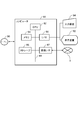
- FIG. 1 is a functional block diagram showing a logical configuration of an information processing device 100 according to the embodiment of the present invention.
- the information processing device 100 includes an acquisition unit 102, a conversion unit 104, and a generation unit 106.
- the acquisition unit 102 is a table 10 defined for each of a plurality of parts, and includes first information that is at least a part of one of the specifications and requirements of the part, and at least a part of one of the specifications and requirements of the part. Then, a plurality of tables showing the relationship between the second information different from the first information and the second information are acquired.
- the second information in one table is at least a part of the first information in another table.
- the conversion unit 104 converts the relationship indicated by each of the plurality of tables into elements of the graph database 30 for each table.
- the generation unit 106 generates the graph database 30 by combining a plurality of elements after conversion of a plurality of tables.
- acquisition means that the device itself acquires data or information stored in another device or a storage medium (active acquisition), for example, requests or queries another device.
- FIG. 2 is a diagram showing an example of the configuration of a computer 80 that realizes the information processing apparatus 100 of this embodiment.
- the computer 80 includes a CPU (Central Processing Unit) 82, a memory 84, a program 90 that realizes the components of FIG. 2 loaded in the memory 84, a storage 85 that stores the program 90, and an I/O (Input). /Output) 86, and a network connection interface (communication I/F 87).
- a CPU Central Processing Unit
- the CPU 82, memory 84, storage 85, I/O 86, and communication I/F 87 are connected to each other via a bus 89, and the CPU 82 controls the entire computer 80.
- the method of connecting the CPU 82 and the like to each other is not limited to bus connection.
- the memory 84 is a memory such as a RAM (Random Access Memory) or a ROM (Read Only Memory).
- the storage 85 is a storage device such as a hard disk, SSD (Solid State Drive), or memory card. Further, the storage 85 may be a memory such as a RAM or a ROM.
- Each function of the information processing apparatus 100 can be realized by the CPU 82 reading the program 90 stored in the storage 85 into the memory 84 and executing the program 90.
- the I/O 86 controls input/output of data and control signals between the computer 80 and other input/output devices.
- Other input/output devices include, for example, an input device 94 such as a keyboard, a touch panel, a mouse, and a microphone connected to the computer 80, an output device such as a display device 92, a printer, and a speaker, and these input/output devices. And an interface of the computer 80. Further, the I/O 86 may control the input/output of data to/from a reading/writing device (not shown) of another recording medium.
- the communication I/F 87 is a network connection interface for communicating between the computer 80 and an external device.
- the communication I/F 87 may be a network interface for connecting to a wired line or a network interface for connecting to a wireless line.
- the computer 80 that implements the information processing apparatus 100 may communicate with another computer (not shown) via the network 3 by the communication I/F 87.
- Each component of the information processing apparatus 100 of the present embodiment of FIG. 1 is realized by an arbitrary combination of hardware and software of the computer 80 of FIG. It will be understood by those skilled in the art that there are various modified examples of the method and device for realizing the same.
- the functional block diagram showing the information processing apparatus 100 of each embodiment to be described below does not show the configuration in hardware units but shows blocks in logical function units.
- the computer program 90 is a table 10 defined for each of a plurality of parts in the computer 80 for realizing the information processing apparatus 100 and is at least a part of one of specifications and requirements of the part.
- the computer program 90 of this embodiment may be recorded in a recording medium that can be read by the computer 80.
- the recording medium is not particularly limited, and various forms are conceivable.
- the program 90 may be loaded from the recording medium into the memory 84 of the computer 80, or may be downloaded to the computer 80 via a network and loaded into the memory 84.
- the recording medium for recording the computer program 90 includes a medium that can be used by the non-transitory tangible computer 80, and the program code readable by the computer 80 is embedded in the medium.
- the computer program 90 When the computer program 90 is executed on the computer 80, it causes the computer 80 to execute an information processing method for realizing the information processing apparatus 100.
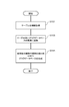
- FIG. 3 is a flowchart showing an example of the operation of the information processing device 100 according to the embodiment of the present invention.
- the information processing apparatus 100 acquires a plurality of tables 10. (Step S101).
- the table 10 is a table defined for each of a plurality of parts, and includes first information that is at least a part of one of the specifications and requirements of the part and at least a part of one of the specifications and requirements of the part. The relationship between the first information and the second information different from the first information is shown.
- the information processing apparatus 100 converts the relationship indicated by each of the plurality of tables 10 into the elements of the graph database 30 for each table (step S103).
- the information processing apparatus 100 generates the graph database 30 by combining the plurality of converted elements of the plurality of tables 10 (step S105).
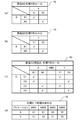
- FIG. 4 is a diagram showing an example of each table 10 of the present embodiment acquired by the acquisition unit 102.
- a plurality of types of parts A two parts A1 and A2 having different specifications
- a part B two parts B1 and B2 having different specifications
- a part C four parts C1, C2, C3 having different specifications
- the table 10 is, for example, a Microsoft Excel (registered trademark) file, another spreadsheet file, CSV (Comma-Separated Values) format, text format, HTML (HyperText Markup Language) format, XML (Extensible Markup Language) format, etc. It can be acquired as file data of various formats such as a file.
- CSV Common-Separated Values
- HTML HyperText Markup Language
- XML Extensible Markup Language
- FIG. 4A is a table 10 showing the rules for the part A and the specification X.
- the part A has two types (A1 and A2) and has different specifications X1 and X2.
- the check marks in the table 10 indicate the corresponding specifications and parts.
- the table 10 indicates that the component A1 is required to realize the specification X1 and the component A2 is necessary to realize the specification X2. That is, the part A1 is a necessary condition for the specification X1 and the part A2 is a necessary condition for the specification X2.
- the first information is the model (A1, A2) of the part A
- the second information is the specification (X1, X2).
- the first information may be the specification and the second information may be the model of the part.
- FIG. 4B is a table 10 showing the rules for the part B and the specification Y.
- the part B has two types (B1 and B2) and has different specifications Y1 and Y2.
- this table 10 indicates that the component B1 is necessary to realize the specification Y1 and the component B2 is necessary to satisfy the specification Y2.
- FIG. 4C is a table 10 showing the rules for the parts C, A and the specification Y.
- the component C includes four components C1 to C4 having different specifications.
- the model of the component C corresponding to the combination of the component A and the specification Y is associated.
- the component C1 is associated with the combination of the component A1 and the specification Y1. That is, it is necessary to combine the component C1 when making a product having the specification Y1 using the component A1.
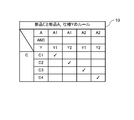
- the table 10 can also define conditional expressions.
- the column of the conditional expression is added between the columns of the items of the table 10.
- the table 10 as shown in FIG. 5 can be considered, but is not limited to these.
- conditional expression the logical product (AND) of the logical operators is used as the conditional expression, but a logical sum (OR), a negation (NOT), a negative logical product (NAND), or the like may be used.
- it may be defined using a conditional expression for determining a character string such as starting (including or ending) with “abc”.
- the acquisition unit 102 may detect a contradiction in the acquired table 10. For example, it may be possible to detect that an unregistered component is included in the table 10 that defines the relationship between a certain specification and a registered component, and notify the operator by displaying an error message or the like.
- the conversion unit 104 shows that each table 10 is converted into an element of the graph database 30.
- the graph database 30 includes, as elements, a node 32 indicating a component or a specification and a relation 34 indicating a relationship between the nodes 32.
- the node 32 has a value (numerical value, character string, etc.) of the model or specification of the component as a property indicating the attribute value.
- the relation 34 has, as properties showing the relationship between the nodes 32, the direction and meaning of the relationship (for example, “REQUIRE” indicating that the specification X1 requires the component A1).
- the direction of the arrow indicates the direction of the relationship and the part A1 is a necessary condition for the specification X1, the specification X1 ⁇ part A1.
- the specification X1 may indicate that it is a sufficient condition for the component A1.
- the arrow in FIG. 6 is part A1 ⁇ specification X1.
- the label becomes "USED_AT" indicating that the component A1 is used in the specification X1.
- the conversion unit 104 converts each item of the table 10, for example, the part A and the specification X, and the part B and the specification Y into the node 32. Then, the nodes 32 are connected by arrows, and the relationship is shown by a relation 34.
- the relation 34 indicates that the specification X2 requires the part A2.
- each node 32 and relation 34 can have properties.
- table 10 shown in FIG. 4C that is, the table 10 of the rules of the parts C, A and specifications Y is converted, it becomes as shown in FIG.
- table 10 shown in FIG. 4D that is, the table 10 of the combination rule of the specifications X and Y is converted, it becomes as shown in FIG.
- the generation unit 106 generates the graph database 30 shown in FIG. 9 by combining the respective elements of FIGS. 6 to 8 converted by the conversion unit 104.
- a plurality of information tables of specifications and requirements of parts are prepared, the relationship indicated by each table is converted into elements of the graph database 30 for each table, and the elements after conversion are combined.
- the graph database 30 can be generated with.
- the table 10 is prepared for each part, even if the part is changed due to a partial specification change of the product or the specification of the part is changed, only the table 10 of the changed part is changed and the graph database is changed. Since it is sufficient to generate 30 again, the influence of the change is small. Further, since the confirmation accompanying the change may be made only by the table 10 of the changed parts, the work load is small and mistakes can be reduced.
- FIG. 10 is a functional block diagram showing a logical configuration of the information processing device 100 according to the embodiment of the present invention.
- the information processing apparatus 100 of FIG. 10 further includes a display control unit 110 in addition to the configuration of the above-described embodiment of FIG.
- FIG. 10 shows an example in which the configuration of FIG. 1 is combined, the configuration of other embodiments may be combined.
- the information processing apparatus 100 according to the present embodiment is the same as the above-described embodiment, except that the graph database 30 generated in the above-described embodiment of FIG. 1 is re-evaluated and the graph database 30 is displayed.
- the display control unit 110 causes the display device 92 of the computer 80 to display the other items connected to the item and their connections in a distinguishable manner.
- the items are, for example, in the case of the graph database 30 of FIG. 9, parts (A1, A2, B1, B2, C1 to C3), specifications (X1, X2, Y1, Y2), and products. It is at least one of (VAR1 to VAR4).
- the display control unit 110 can display a screen on which the graph database 30 of FIG. 9 is drawn on the display device 92 and accept an operation of selecting a certain item by the operator using the input device 94.
- the display control unit 110 may display a screen in which a graph 38 as shown in FIG. 11 is drawn when the operator selects a certain product variation VAR1.
- the display control unit 110 displays only the screen in which the final graph 38 shown in FIG. 12 is drawn as the search result. It may be displayed.
- the three logical operators AND in the graph 38 of the product variation VAR1 include those in which the conditions of the part A and the specification Y required by the part C are not defined (in the figure). , The part surrounded by the broken line).
- the specification Y2 is not included in the graph 38 of FIG. 11 among the parts A1 and the specifications Y2 which are the necessary conditions for the part C2 shown in FIG.
- the condition of the component C2 is insufficient.
- the parts A2 and the specifications Y1 which are the necessary conditions for the parts C3 shown in FIG. 7 the parts A2 are not included in the graph 38 of FIG. 11, so the conditions for the parts C3 are insufficient. In this way, the paths of the parts C2 and C3 whose conditions are insufficient are excluded.
- This final graph 38 shows that the combination of parts that satisfy the specifications X1 and Y1 of the product variation VAR1 is A1, B1 and C1 (parts indicated by arrows in the figure).
- the display control unit 110 displays the graph 38 obtained by re-evaluation by the generation unit 106.
- the information processing apparatus 100 of the present embodiment it is possible to efficiently obtain the necessary condition for satisfying a certain specification of a certain product.
- the result thus obtained may be output by the display control unit 110 as the table 40 of FIG. 13, for example.
- the table 40 may be displayed or output as a data file.
- the table 40 shows combinations of parts A, B, and C with respect to combinations of specifications X and Y.
- the table 40 shows which parts (VAR1 to VAR4) having the combination of the specifications (X, Y) can be realized by combining the parts.
- the information processing apparatus 100 may further include a detection unit (not shown) that detects an error such as a route not being connected in the process of performing processing based on the table 10 in the conversion unit 104 and the generation unit 106.
- a detection unit (not shown) that detects an error such as a route not being connected in the process of performing processing based on the table 10 in the conversion unit 104 and the generation unit 106.
- the detection unit may say that "the condition for selecting a certain component does not exist (for example, the component C1 is not selected for any variation of VAR1 to VAR4)" or "there are a plurality of components selected under a certain condition. Existing (both components C1 and C2 are selected under the condition of VAR1)”. However, when there are parts having the same function but different colors, a plurality of parts may be selected under certain conditions, and in such a case, no error is generated.
- the detection unit may notify the operator of the information of the table 10 in which the error is detected.
- Information of the data file of the table 10 in which the error is detected (file name or path information) may be notified, and the item in the table 10 corresponding to the element associated with the route in which the error is detected may be notified. It may be highlighted. Alternatively, on the screen of the graph database 30 shown in FIG. 9, the location where the route is not connected may be displayed by blinking or the like.
- FIG. 14 is a functional block diagram showing a logical configuration of the information processing device 100 according to the embodiment of the present invention.
- the information processing apparatus 100 according to the present embodiment further includes a search unit 120 in addition to the configuration of the above embodiment of FIG.
- FIG. 14 shows an example in which the configuration of FIG. 10 is combined, the configuration of other embodiments may be combined.
- the search unit 120 searches for connections between a plurality of items regardless of the direction of the relation 34 in the graph database 30.
- the search unit 120 also generates relationship data indicating the relationship between items and the directionality thereof, and adds the generated relationship data to the graph database 30.
- FIG. 15 is a flowchart showing an example of the processing procedure of the search unit 120.
- the search unit 120 searches for combinations of nodes 32 that satisfy the specified search conditions.
- the information processing apparatus 100 functions as a configurator that determines the configuration and specifications of a personal computer that is a product will be described as an example.
- the search unit 120 acquires the relationship between the items corresponding to the first information and the second information in the table 10 and the direction of the relationship between the items (step S201).
- FIG. 16 is a diagram for explaining an example of adding relational data to the graph database 30 using the two tables 10.
- FIG. 16A shows a table 10 showing the relationship between the sales market of personal computers (indicated as “Market” in the figure) (JAPAN and USA) and the sizes of liquid crystal displays (13 inches and 15 inches).
- FIG. 16B shows the size of the liquid crystal display of the personal computer (indicated as “Size” in the drawing) (13 inches and 15 inches) and the performance of the CPU (2.3 GHz, 2.5 GHz, 2.8 GHz, 2.
- 9 shows a table 10 showing a relationship with (9 GHz).
- FIG. 16C is a diagram for explaining the relational data.
- the nodes 32 of the graph database 30 are grouped by corresponding items and added as a higher-order item node 42, and further, a relation 44 between the item nodes 42 (hereinafter, “relationship between items”). 44”) is added.
- the relationship (relation 34) between the nodes 32 of the graph database 30 is indicated by a dashed arrow.
- the relationship 44 between items has a direction 46 according to the definition of the table 10, as indicated by the solid arrow. Note that the relation 34 and the relationship 44 are not limited to the broken line and the solid line, and may be displayed in a mutually distinguishable manner.
- the relational data is an arrow added to the graph database 30 to indicate the item node 42, the relation 44 between the items, and the direction 46 between the items.
- the generation unit 106 adds these relational data to the graph database 30.
- the generation unit 106 aligns the directions of the relationships 44 between the items with the directions of the relations 34 between the nodes 32 and registers them in the graph database 30.
- the direction between items indicates the relationship of necessary and sufficient conditions for items, and if item A is item B (that is, item B is a necessary condition for item A, or item A is a sufficient condition for item B).
- the arrow points in the direction from item A to item B.
- the display control unit 110 may display the graph database 30 of FIG. 16(c). Of the elements of the graph database 30 of FIG. 16C, the node 32 of each item may be hidden and only the item node 42 may be displayed. Alternatively, when the item node 42 is selected, the node 32 immediately below it may be switched to display or non-display.
- the display control unit 110 may display the added relational data in different shapes, colors, and display forms (highlights, blinks, animations, etc.) so as to be distinguishable from the elements of the original graph database 30.
- the search unit 120 defines the search route between the item nodes 42 based on the acquired relation 44 between items and the direction thereof (step S203 in FIG. 15).
- FIG. 17 is a diagram showing an example of the search route, the received search condition, and the search result.
- Item nodes 42 n1, n2, n3 and a relationship 44 between items are defined in the search path shown in the first line of FIG. 17(a).
- the direction of the arrow of the portion 47 surrounded by the broken line indicates the direction of the relationship 44.
- the search unit 120 first searches the search route based on the item node 42 registered in the graph database 30 and the relationship 44 between the items.
- the search path is defined including the direction of the relation 44 between items.
- the search unit 120 accepts the search condition (step S205 in FIG. 15) and searches the combination of the nodes 32 of the graph database 30 satisfying the search condition according to the defined search path (step S207 in FIG. 15).
- the search unit 120 can specify the direction of the relation 34 between the plurality of nodes 32 based on the direction of the relationship 44 between items, regardless of the direction of the relationship 44 between items on the search path. You can search along the route. In other words, even if the search route includes the forward direction along the route and the opposite direction as the direction of the relation 44 between items, the direction of the relation 34 is determined based on the direction of the relation 44 between items. Since the node 32 can be specified, the node 32 can be searched for along the route.
- search conditions are specified.
- a search condition for searching a possible value of the CPU when the market (JAPAN) and the size of the liquid crystal display (13 inches) are specified is specified. Then, it is specified that the value of each node 32 is returned as the search result.
- ni.type (i is a natural number) indicates the specification type of the node ni
- ni.value indicates the specification value of the node ni.
- FIG. 17B is a diagram showing an output example of the result of the search according to the search route of FIG.
- the search result by the search unit 120 is displayed by the display control unit 110 as the screen of FIG.
- the search result may be output as a data file.
- the node 32 satisfying the search condition is extracted from the plurality of nodes 32 of each item on the route regardless of the defined direction, and the value of the extracted node 32 of each item is obtained as the search result. To be done.
- FIG. 18A is the same as that in FIG. 16A.
- the relationship between the items of the table 10 showing the relationship between the liquid crystal display and the CPU is opposite to that of FIG. 16B.
- the search unit 120 performs a search according to the search conditions defined in the second and subsequent lines in FIG. At that time, the search unit 120 performs the search along the route defined by the search route, but regardless of the direction of the relation 44 between the items.
- the search result obtained as a result is as shown in FIG. 19B, which is the same as the search result of FIG. 17B.
- the table 10 shows the relationship between the size of the liquid crystal display (13 inches, 15 inches), the touch bar (presence/absence), and the storage capacity (128 GB, 256 GB, 512 GB).
- “w/” indicates that the touch bar is included
- “w/o” indicates that the touch bar is not included.
- the relation 44 between the item nodes 42 is also “Size x Touch Bar-Storage” and the logical operation as shown in FIG. It is indicated by a label that includes children (“x” indicating a logical product).
- x indicating a logical product
- two routes are defined as search routes.
- the search unit 120 searches along the route.
- the node 32 satisfying the search condition is extracted from the plurality of nodes 32 of each item on the route, and the value of the extracted node 32 of each item is acquired as the search result.
- the display control unit 110 displays the search result of FIG.
- the search unit 120 performs the search regardless of the direction of the relationship between the items, and therefore the items of the table 10 Even if the definition of the relationship is reversed, the search can be performed without problems. Further, in the present embodiment, instead of following the node 32 and the relation 34, a route between the item node 42 in which the node 32 is grouped and the relation 44 between the items is defined, and the search is performed while following the route. Since the node 32 satisfying the condition is searched, the time required for the search can be shortened and the search can be performed efficiently.
- the information processing apparatus 100 of this embodiment has the same configuration as the information processing apparatus 100 of FIG.
- the table 10 used by the generation unit 106 can be switched. Then, the display control unit 110 receives the selection of the table 10 to be used, and displays the graph database 30 generated using the selected table 10. In other words, the graph database 30 generated by the generation unit 106 differs depending on the selected table 10. Further, the display control unit 110 can also display the graph databases 30 generated based on each of the plurality of tables 10 in an overlapping manner.
- FIG. 23 shows two first tables 10a and two tables 10b based on two different design specifications and design conditions regarding the size of the liquid crystal display and the performance of the CPU.
- FIG. 24 is a diagram showing a graph database 30 generated using the first table 10a and the second table 10b of FIG. 23 and the table 10 regarding the market and the size of the liquid crystal display.
- the graph database 30 has a relationship 44 (Size-CPU #1) based on the first table 10a and a relationship 44 (Size-CPU #2) based on the second table 10b. Both are included.
- the display control unit 110 displays a screen in which the graph database 30 of FIG. 24(b) is drawn, and displays the relationship 44 (Size-CPU #1) based on the first table 10a in the displayed graph database 30.
- a screen drawing the graph database 30 corresponding to only the selected relationship 44 is displayed.
- the identification information and the combination of the table 10 are associated and registered for each design specification, and the graph database 30 that is generated for each design specification is registered. Is also associated with the identification information. Then, by accepting the designation of the identification information of the design specification, the graph database 30 corresponding to the design specification of the designated identification information can be called. Further, the table 10 registered in association with the identification information of the design specifications may include at least the table 10 that switches between different design specifications. The table 10 common to different design specifications may be registered as common information.
- FIG. 25 is a diagram showing a screen on which the graph database 30 is drawn when the relationship 44 (Size-CPU #1) based on the first table 10a is selected.
- FIG. 26 is a diagram showing a screen on which the graph database 30 is drawn when the relationship 44 (Size-CPU #2) based on the second table 10b is selected.
- the display control unit 110 determines the table 10 corresponding to the selected relation 44 in the graph database 30 generated using the plurality of tables 10 having different design specifications and design conditions, Only the corresponding graph 38 is extracted and displayed, and the graph 38 of the table 10 corresponding to the unselected relation 44 is hidden. Alternatively, those not selected are displayed such that the display color is lightened so as to be distinguishable from the selected ones, and the selected ones are preferentially viewed.
- the display control unit 110 may also display a screen 200 as shown in FIG.
- This screen 200 hierarchically displays the item nodes 42 and the relationships 44 of the graph database 30.
- a plurality of item nodes 42 directly connected to a certain item node 42 and the relation 44 are arranged and displayed in the same row or column.
- the selected layer may be displayed or hidden, or if a certain layer is selected, the layer immediately below that layer may be displayed or hidden. Further, when the item node 42 in the hierarchy is selected, the corresponding node 32 and the node 32 and the relation 34 related to the node 32 may be displayed.
- the table 10 of the plurality of different design specifications and design conditions is used. It is possible to generate the graph database 30 and select the table 10 according to the specifications to switch and display the graph database 30. Therefore, it becomes possible to examine while switching and evaluating a plurality of alternatives.
- the information processing apparatus 100 may further include a storage unit (not shown) that stores the generated graph database 30 in the storage 85 (or the memory 84) of the computer 80.
- the storage unit stores the generated graph database 30 in association with, for example, the generation time or the storage time, and the information of the plurality of tables 10 used to generate the graph database 30, thereby storing the design specifications and the design. It can be managed as a condition change history.
- the generated graph database 30 may be stored with different identification information or names.
- the information processing apparatus 100 may have a configuration that analyzes an influence range due to a part of the design specifications being changed.
- the information processing apparatus 100 further includes a specifying unit (not shown) that specifies an item corresponding to the changed specification and requirement of the component when at least a part of the specification and requirement of the component of the table 10 is changed. Good.
- the display control unit 110 changes the shape, the color, and the display form (highlight, blink, animation, and the like) so that the other items connected to the specified item and the connection thereof can be identified and displayed. According to this configuration, when a specific design specification is changed, the influence range can be displayed in a distinguishable manner, so that the influence range can be analyzed.
- the table 10 may be switched, or the relationship 44 between specifications indicating the changed design specification may be instructed.
- the display control unit 110 may distinguish the direct influence range and the subsequent influence range so as to be distinguishably displayed. Further, the images may be displayed so that they can be identified in the order in which they are affected.
- FIG. 28 shows an example in which when the design specifications of the Size-Touch Bar in FIG. 27 are changed, the direct impact range and the subsequent impact range are distinguished and displayed in a distinguishable manner.
- Touch Bar has two selection conditions of w/ and w/o, but it is changed to three selection conditions of w/(Large), w/(Small), and w/o. . It is also shown that Touch Bar affects the three design specifications of Sizex Touch Bar-Graphics, Size x Touch Bar-Interface, and Size x Touch Bar-Storage included in the design specifications.
- the double line indicates the direct influence range
- the alternate long and short dash line indicates the influence range thereafter, but as described above, each influence range has a shape, a color, a display form (highlight, Blinks, animations, etc.) are displayed separately.
- the operator can recognize that it is necessary to change the three design specifications of SizexTouchBar-Graphics, SizexxTouchBar-Interface, and SizexTouchBar-Storage.
- Size-CPU is changed, only the selection of CPU is changed and it does not affect other design specifications. In this case, it may be displayed that there is no effect.
- FIG. 29 shows an example in which the design specifications of Size-Touch Bar are changed and the combination conditions of Touch Bar and Size are changed. It is shown that both Size and Touch Bar are included in the design specifications, which affects the three design specifications of Sizex Touch Bar-Graphics, Size x Touch Bar-Interface, and Size x Touch Bar-Storage. By this, the operator can recognize that it is necessary to change the three design specifications of SizexTouchBar-Graphics, SizexxTouchBar-Interface, and SizexTouchBar-Storage.
- a procedure for acquiring a plurality of tables showing the relationship between the second information different from the information and The second information in one table is at least part of the first information in another table,
- a program for causing a computer to execute the procedure of adding the generated relational data to the graph database 6. 1. To 5. In the program described in any one of, When generating the graph database, the table used is switchable, A program for causing a computer to further execute the procedure of displaying the graph database generated using the selected table. 7. 1. To 6. In the program described in any one of, A program for causing a computer to further execute a procedure of arranging and displaying a plurality of items directly connected to a certain item so that they are arranged in the same row or column. 8. 1. To 7.
- Table acquisition means for acquiring a plurality of tables showing the relationship between the second information different from the information and The second information in one table is at least part of the first information in another table, Conversion means for converting the relationship indicated by each of the plurality of tables into elements of a graph database for each table; Generating means for generating the graph database by combining the plurality of elements after conversion of the plurality of tables;
- An information processing apparatus including. 11. 10. In the information processing device described in An information processing apparatus further comprising: a display unit that, when a certain item is selected in the generated graph database, displays another item connected to the item and its connection in a distinguishable manner. 12. 10. Or 11. In the information processing device described in An information processing apparatus in which the directionality of the relationship is defined in the graph database. 13. 10. Or 11.
- the directionality of the relationship is defined
- a route indicating a connection between a plurality of items is searched regardless of the direction of the relationship, and a combination of the elements satisfying the search condition along the route is searched.
- An information processing apparatus further comprising a search unit for searching for. 14. 12. Or 13.
- the generating means is Generates relationship data indicating the relationship between the items and their direction, An information processing apparatus for adding the generated relational data to the graph database. 15. 10. To 14.
- the information processing apparatus can switch the table to be used when generating the graph database,
- the information processing apparatus further comprising display means for displaying the graph database generated using the selected table. 16. 10. To 15. In the information processing device according to any one of An information processing apparatus further comprising a display unit for displaying a plurality of items directly connected to a certain item so as to be arranged in the same row or column. 17. 10. To 16. In the information processing device according to any one of An information processing apparatus further comprising: a unit that stores the generated graph database in a storage device by associating the information of the table used when generating the graph database. 18. 10. To 17.
- the display means is An information processing device, which distinguishably displays other items connected to the specified item and the connection. 19.
- the information processing device A table defined for each of a plurality of parts, the first information being at least a part of one of specifications and requirements of the part, and the first information being at least a part of one of specifications and requirements of the part.
- the information processing device is In the generated graph database, when a search condition is specified, a path indicating a connection between a plurality of items is searched regardless of the direction of the relationship, An information processing method for searching a combination of the elements that satisfy the search condition along the path. 23. 21. Or 22.
- the information processing device is Generates relationship data indicating the relationship between the items and their direction, An information processing method for adding the generated relational data to the graph database. 24. 19. To 23.
- the information processing method described in any one of When generating the graph database the table used is switchable, The information processing device is An information processing method for displaying the graph database generated using the selected table. 25. 19.
- any one of The information processing device is An information processing method in which a plurality of items directly connected to a certain item are arranged and displayed in the same row or column. 26. 19. To 25.
- the information processing method described in any one of The information processing device is An information processing method in which the generated graph database is stored in a storage device in association with the information of the table used when the graph database is generated. 27. 19. To 26.
- the information processing method described in any one of The information processing device is When at least a part of the specifications and the requirements of the parts of the table is changed, the items corresponding to the specifications and the requirements of the changed parts are specified, An information processing method, wherein other items connected to the specified item and the connection are displayed in a distinguishable manner.
Landscapes
- Engineering & Computer Science (AREA)
- Theoretical Computer Science (AREA)
- Databases & Information Systems (AREA)
- Data Mining & Analysis (AREA)
- Physics & Mathematics (AREA)
- General Engineering & Computer Science (AREA)
- General Physics & Mathematics (AREA)
- Information Retrieval, Db Structures And Fs Structures Therefor (AREA)
Abstract
情報処理装置(100)は、複数の部品別に定義されたテーブルであって、当該部品の仕様及び要件の一方の少なくとも一部である第1の情報と、当該部品の仕様及び要件の一方の少なくとも一部であり第1の情報とは異なる第2の情報と、の関係を示すテーブルを複数取得する取得部(102)と、あるテーブルにおける第2の情報は、他のテーブルの第1の情報の少なくとも一部であり、複数のテーブルのそれぞれが示す関係をテーブル別にグラフデータベースの要素に変換する変換部(104)と、複数のテーブルの変換後の複数の要素を組み合わせることにより、グラフデータベースを生成する生成部(106)と、を備える。
Description
本発明は、情報処理装置、情報処理方法、およびプログラムに関する。
近年、膨大なデータを、データ間のつながりに着目して効率よく分析する手法として、グラフデータベースが利用されるようになってきている。
特許文献1には、グラフデータベースの検索を行う際に、検索パターンを分類することでパターン数を低減して、ユーザに選択し易くする技術が記載されている。
特許文献1には、グラフデータベースの検索を行う際に、検索パターンを分類することでパターン数を低減して、ユーザに選択し易くする技術が記載されている。
製品設計において、部品の仕様や要件はテーブル形式のデータベース(例えば、リレーショナルデータベース)で管理されている場合がほとんどである。近年は、ある部品の要件の一つに、他の部品の仕様が入っていたり、ある部品に求められる仕様が階層化されていたりする。このため、複数の部品間の関連性を把握することが難しくなっている。
本発明は上記事情に鑑みてなされたものであり、その目的とするところは、製品における複数の部品の仕様および要件の関連性を効率良く管理できる技術を提供することにある。
本発明の各側面では、上述した課題を解決するために、それぞれ以下の構成を採用する。
第一の側面は、情報処理装置に関する。
第一の側面に係る情報処理装置は、
複数の部品別に定義されたテーブルであって、当該部品の仕様及び要件の一方の少なくとも一部である第1の情報と、当該部品の仕様及び要件の一方の少なくとも一部であり前記第1の情報とは異なる第2の情報と、の関係を示すテーブルを複数取得するテーブル取得手段と、
あるテーブルにおける前記第2の情報は、他のテーブルの前記第1の情報の少なくとも一部であり、
複数の前記テーブルのそれぞれが示す前記関係を前記テーブル別にグラフデータベースの要素に変換する変換手段と、
複数の前記テーブルの変換後の複数の前記要素を組み合わせることにより、前記グラフデータベースを生成する生成手段と、を有する。
第一の側面に係る情報処理装置は、
複数の部品別に定義されたテーブルであって、当該部品の仕様及び要件の一方の少なくとも一部である第1の情報と、当該部品の仕様及び要件の一方の少なくとも一部であり前記第1の情報とは異なる第2の情報と、の関係を示すテーブルを複数取得するテーブル取得手段と、
あるテーブルにおける前記第2の情報は、他のテーブルの前記第1の情報の少なくとも一部であり、
複数の前記テーブルのそれぞれが示す前記関係を前記テーブル別にグラフデータベースの要素に変換する変換手段と、
複数の前記テーブルの変換後の複数の前記要素を組み合わせることにより、前記グラフデータベースを生成する生成手段と、を有する。
第二の側面は、少なくとも1つのコンピュータにより実行される情報処理方法に関する。
第二の側面に係る情報処理方法は、
情報処理装置が、
複数の部品別に定義されたテーブルであって、当該部品の仕様及び要件の一方の少なくとも一部である第1の情報と、当該部品の仕様及び要件の一方の少なくとも一部であり前記第1の情報とは異なる第2の情報と、の関係を示すテーブルを複数取得し、
あるテーブルにおける前記第2の情報は、他のテーブルの前記第1の情報の少なくとも一部であり、
複数の前記テーブルのそれぞれが示す前記関係を前記テーブル別にグラフデータベースの要素に変換し、
複数の前記テーブルの変換後の複数の前記要素を組み合わせることにより、前記グラフデータベースを生成する、ことを含む。
第二の側面に係る情報処理方法は、
情報処理装置が、
複数の部品別に定義されたテーブルであって、当該部品の仕様及び要件の一方の少なくとも一部である第1の情報と、当該部品の仕様及び要件の一方の少なくとも一部であり前記第1の情報とは異なる第2の情報と、の関係を示すテーブルを複数取得し、
あるテーブルにおける前記第2の情報は、他のテーブルの前記第1の情報の少なくとも一部であり、
複数の前記テーブルのそれぞれが示す前記関係を前記テーブル別にグラフデータベースの要素に変換し、
複数の前記テーブルの変換後の複数の前記要素を組み合わせることにより、前記グラフデータベースを生成する、ことを含む。
なお、本発明の他の側面としては、上記第二の側面の方法を少なくとも1つのコンピュータに実行させるプログラムであってもよいし、このようなプログラムを記録したコンピュータが読み取り可能な記録媒体であってもよい。この記録媒体は、非一時的な有形の媒体を含む。
このコンピュータプログラムは、コンピュータにより実行されたとき、コンピュータに、情報処理装置上で、その情報処理方法を実施させるコンピュータプログラムコードを含む。
このコンピュータプログラムは、コンピュータにより実行されたとき、コンピュータに、情報処理装置上で、その情報処理方法を実施させるコンピュータプログラムコードを含む。
なお、以上の構成要素の任意の組合せ、本発明の表現を方法、装置、システム、記録媒体、コンピュータプログラムなどの間で変換したものもまた、本発明の態様として有効である。
また、本発明の各種の構成要素は、必ずしも個々に独立した存在である必要はなく、複数の構成要素が一個の部材として形成されていること、一つの構成要素が複数の部材で形成されていること、ある構成要素が他の構成要素の一部であること、ある構成要素の一部と他の構成要素の一部とが重複していること、等でもよい。
また、本発明の方法およびコンピュータプログラムには複数の手順を順番に記載してあるが、その記載の順番は複数の手順を実行する順番を限定するものではない。このため、本発明の方法およびコンピュータプログラムを実施するときには、その複数の手順の順番は内容的に支障のない範囲で変更することができる。
さらに、本発明の方法およびコンピュータプログラムの複数の手順は個々に相違するタイミングで実行されることに限定されない。このため、ある手順の実行中に他の手順が発生すること、ある手順の実行タイミングと他の手順の実行タイミングとの一部ないし全部が重複していること、等でもよい。
上記各側面によれば、製品における複数の部品の仕様および要件の関連性を効率良く管理できる技術を提供することができる。
上述した目的、およびその他の目的、特徴および利点は、以下に述べる好適な実施の形態、およびそれに付随する以下の図面によってさらに明らかになる。
以下、本発明の実施の形態について、図面を用いて説明する。尚、すべての図面において、同様な構成要素には同様の符号を付し、適宜説明を省略する。
(第1の実施の形態)
図1は、本発明の実施の形態に係る情報処理装置100の論理的な構成を示す機能ブロック図である。
情報処理装置100は、取得部102と、変換部104と、生成部106と、を備える。
取得部102は、複数の部品別に定義されたテーブル10であって、当該部品の仕様及び要件の一方の少なくとも一部である第1の情報と、当該部品の仕様及び要件の一方の少なくとも一部であり第1の情報とは異なる第2の情報と、の関係を示すテーブルを複数取得する。
あるテーブルにおける第2の情報は、他のテーブルの第1の情報の少なくとも一部である。
変換部104は、複数のテーブルのそれぞれが示す関係をテーブル別にグラフデータベース30の要素に変換する。
生成部106は、複数のテーブルの変換後の複数の要素を組み合わせることにより、グラフデータベース30を生成する。
図1は、本発明の実施の形態に係る情報処理装置100の論理的な構成を示す機能ブロック図である。
情報処理装置100は、取得部102と、変換部104と、生成部106と、を備える。
取得部102は、複数の部品別に定義されたテーブル10であって、当該部品の仕様及び要件の一方の少なくとも一部である第1の情報と、当該部品の仕様及び要件の一方の少なくとも一部であり第1の情報とは異なる第2の情報と、の関係を示すテーブルを複数取得する。
あるテーブルにおける第2の情報は、他のテーブルの第1の情報の少なくとも一部である。
変換部104は、複数のテーブルのそれぞれが示す関係をテーブル別にグラフデータベース30の要素に変換する。
生成部106は、複数のテーブルの変換後の複数の要素を組み合わせることにより、グラフデータベース30を生成する。
本明細書において、「取得」とは、自装置が他の装置や記憶媒体に格納されているデータまたは情報を取りに行くこと(能動的な取得)、たとえば、他の装置にリクエストまたは問い合わせして受信すること、他の装置や記憶媒体にアクセスして読み出すこと等、および、自装置に他の装置から出力されるデータまたは情報を入力すること(受動的な取得)、たとえば、配信(または、送信、プッシュ通知等)されるデータまたは情報を受信すること等、の少なくともいずれか一方を含む。また、受信したデータまたは情報の中から選択して取得すること、または、配信されたデータまたは情報を選択して受信することも含む。
図2は、本実施形態の情報処理装置100を実現するコンピュータ80の構成の一例を示す図である。
本実施形態のコンピュータ80は、CPU(Central Processing Unit)82、メモリ84、メモリ84にロードされた図2の構成要素を実現するプログラム90、そのプログラム90を格納するストレージ85、I/O(Input/Output)86、およびネットワーク接続用インタフェース(通信I/F87)を備える。
本実施形態のコンピュータ80は、CPU(Central Processing Unit)82、メモリ84、メモリ84にロードされた図2の構成要素を実現するプログラム90、そのプログラム90を格納するストレージ85、I/O(Input/Output)86、およびネットワーク接続用インタフェース(通信I/F87)を備える。
CPU82、メモリ84、ストレージ85、I/O86、通信I/F87は、バス89を介して互いに接続され、CPU82によりコンピュータ80全体が制御される。ただし、CPU82などを互いに接続する方法は、バス接続に限定されない。
メモリ84は、RAM(Random Access Memory)やROM(Read Only Memory)などのメモリである。ストレージ85は、ハードディスク、SSD(Solid State Drive)、またはメモリカードなどの記憶装置である。また、ストレージ85は、RAMやROMなどのメモリであってもよい。
CPU82が、ストレージ85に記憶されるプログラム90をメモリ84に読み出して実行することにより、情報処理装置100の各機能を実現することができる。
I/O86は、コンピュータ80と他の入出力装置間のデータおよび制御信号の入出力制御を行う。他の入出力装置とは、たとえば、コンピュータ80に接続されるキーボード、タッチパネル、マウス、およびマイクロフォン等の入力装置94と、表示装置92、プリンタ、およびスピーカ等の出力装置と、これらの入出力装置とコンピュータ80のインタフェースとを含む。さらに、I/O86は、他の記録媒体の読み取りまたは書き込み装置(不図示)とのデータの入出力制御を行ってもよい。
通信I/F87は、コンピュータ80と外部の装置との通信を行うためのネットワーク接続用インタフェースである。通信I/F87は、有線回線と接続するためのネットワークインタフェースでもよいし、無線回線と接続するためのネットワークインタフェースでもよい。たとえば、情報処理装置100を実現するコンピュータ80は、通信I/F87によりネットワーク3を介して他のコンピュータ(不図示)と通信してもよい。
図1の本実施形態の情報処理装置100の各構成要素は、図2のコンピュータ80のハードウェアとソフトウェアとの任意の組合せによって実現される。そして、その実現方法、装置にはいろいろな変形例があることは、当業者には理解されるところである。以下説明する各実施形態の情報処理装置100を示す機能ブロック図は、ハードウェア単位の構成ではなく、論理的な機能単位のブロックを示している。
本実施形態のコンピュータプログラム90は、情報処理装置100を実現させるためのコンピュータ80に、複数の部品別に定義されたテーブル10であって、当該部品の仕様及び要件の一方の少なくとも一部である第1の情報と、当該部品の仕様及び要件の一方の少なくとも一部であり第1の情報とは異なる第2の情報と、の関係を示すテーブル10を複数取得する手順、複数のテーブル10のそれぞれが示す関係をテーブル別にグラフデータベース30の要素に変換する手順、複数のテーブル10の変換後の複数の要素を組み合わせることにより、グラフデータベース30を生成する手順、を実行させるように記述されている。
本実施形態のコンピュータプログラム90は、コンピュータ80で読み取り可能な記録媒体に記録されてもよい。記録媒体は特に限定されず、様々な形態のものが考えられる。また、プログラム90は、記録媒体からコンピュータ80のメモリ84にロードされてもよいし、ネットワークを通じてコンピュータ80にダウンロードされ、メモリ84にロードされてもよい。
コンピュータプログラム90を記録する記録媒体は、非一時的な有形のコンピュータ80が使用可能な媒体を含み、その媒体に、コンピュータ80が読み取り可能なプログラムコードが埋め込まれる。コンピュータプログラム90が、コンピュータ80上で実行されたとき、コンピュータ80に、情報処理装置100を実現する情報処理方法を実行させる。
図3は、本発明の実施の形態に係る情報処理装置100の動作の一例を示すフローチャートである。
情報処理装置100は、テーブル10を複数取得する。(ステップS101)。テーブル10は、複数の部品別に定義されたテーブルであって、当該部品の仕様及び要件の一方の少なくとも一部である第1の情報と、当該部品の仕様及び要件の一方の少なくとも一部であり第1の情報とは異なる第2の情報と、の関係を示す。そして情報処理装置100は、複数のテーブル10のそれぞれが示す関係を、テーブル別に、グラフデータベース30の要素に変換する(ステップS103)。そして情報処理装置100は、複数のテーブル10の変換後の複数の要素を組み合わせることにより、グラフデータベース30を生成する(ステップS105)。
情報処理装置100は、テーブル10を複数取得する。(ステップS101)。テーブル10は、複数の部品別に定義されたテーブルであって、当該部品の仕様及び要件の一方の少なくとも一部である第1の情報と、当該部品の仕様及び要件の一方の少なくとも一部であり第1の情報とは異なる第2の情報と、の関係を示す。そして情報処理装置100は、複数のテーブル10のそれぞれが示す関係を、テーブル別に、グラフデータベース30の要素に変換する(ステップS103)。そして情報処理装置100は、複数のテーブル10の変換後の複数の要素を組み合わせることにより、グラフデータベース30を生成する(ステップS105)。
以下、詳細に説明する。
図4は、取得部102が取得する本実施形態の各テーブル10の例を示す図である。
ここでは、複数種類の部品A(仕様の異なる2つの部品A1とA2)と、部品B(仕様の異なる2つの部品B1とB2)と、部品C(仕様の異なる4つの部品C1、C2、C3、C4)とを組み合わせて作製される製品を例に説明する。
図4は、取得部102が取得する本実施形態の各テーブル10の例を示す図である。
ここでは、複数種類の部品A(仕様の異なる2つの部品A1とA2)と、部品B(仕様の異なる2つの部品B1とB2)と、部品C(仕様の異なる4つの部品C1、C2、C3、C4)とを組み合わせて作製される製品を例に説明する。
テーブル10は、例えば、マイクロソフトエクセル(登録商標)ファイル、他の表計算ソフトのファイル、CSV(Comma-Separated Values)形式、テキスト形式、HTML(HyperText Markup Language)形式、XML(Extensible Markup Language)形式等のファイル等、様々な形式のファイルデータとして取得することができる。
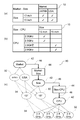
図4(a)は、部品Aと仕様Xとのルールを示すテーブル10である。部品Aは、2つの型式(A1とA2)があり、異なる仕様X1とX2とを有している。図中、テーブル10内のチェックマークは、対応する仕様と部品を示している。言い換えると、このテーブル10は、仕様X1を実現するには部品A1が必要であり、かつ、仕様X2を実現するにはA2が必要であることを示している。つまり、部品A1は仕様X1の必要条件であり、部品A2は仕様X2の必要条件である。本図に示す例では、第1の情報は部品Aの型式(A1、A2)であり、第2の情報は仕様(X1、X2)である。あるいは、第1の情報が仕様で、第2の情報が部品の型式であってもよい。
図4(b)は、部品Bと仕様Yとのルールを示すテーブル10である。部品Bは、2つの型式(B1とB2)があり、異なる仕様Y1とY2とを有している。言い換えると、このテーブル10は、仕様Y1を実現するには部品B1が必要であり、かつ、仕様Y2を条件するには部品B2が必要であることを示している。
図4(c)は、部品Cと部品Aと、仕様Yとのルールを示すテーブル10である。部品Cは、仕様の異なる4つの部品C1~C4を含んでいる。テーブル10は、部品Aと仕様Yとの組み合わせに対応する部品Cの型式が対応付けられている。図の例では、部品A1と仕様Y1との組み合わせに部品C1が対応付けられている。つまり、部品A1を用いて仕様Y1を有する製品を作る場合は、部品C1を組み合わせる必要があることを示している。
このように、テーブル10は、条件式を定義することもできる。図4(c)では、テーブル10の項目の列の間に条件式の列を追加してある。また、他の例として、図5のようなテーブル10も考えられるが、これらに限定されない。
この例では、条件式として論理演算子の論理積(AND)を用いているが、論理和(OR)、否定(NOT)、又は否定論理積(NAND)等でもよい。さらに、ノード32が示す部品や仕様のプロパティの属性値を用いて判定する条件式を、例えば、不等号(>、<)、等号(=)、等号否定(≠)等を用いて定義してもよい。あるいは、「abc」で始まる(含む、又は終わる)等のように文字列を判定する条件式を用いて定義してもよい。
また、取得部102は、取得したテーブル10の矛盾を検出してもよい。例えば、ある仕様と登録済みの部品との関係を定義しているテーブル10において、未登録の部品が含まれていることを検出して操作者にエラーメッセージの表示等で通知してもよい。
本発明の情報処理装置100によって、仕様XとYとを組み合わせたバリエーションの製品が、どの部品を組み合わせることで実現できるかを求めることができる。
そこでまず、仕様XとYとを組み合わせた製品バリエーションを考える。この例では、図4(d)に示すように、組み合わせは4つであり、製品バリエーションVAR1~VAR4となる。
そこでまず、仕様XとYとを組み合わせた製品バリエーションを考える。この例では、図4(d)に示すように、組み合わせは4つであり、製品バリエーションVAR1~VAR4となる。
以下、本発明の情報処理装置100によって4つの製品の各部品の組み合わせを求める方法について説明する。
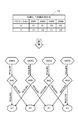
図6~図8は、グラフデータベース30を説明するための図である。変換部104により各テーブル10がグラフデータベース30の要素に変換された様子を示している。
グラフデータベース30は、部品や仕様を示すノード32と、各ノード32間の関係性を示すリレーション34と、を要素として含む。さらに、ノード32は、その属性値を示すプロパティとして、部品の型式や仕様の値(数値又は文字列等)を有する。リレーション34は、ノード32間の関係性を示すプロパティとして、関係性の方向と意味(例えば、仕様X1は部品A1を必要とすることを示す「REQUIRE」)を有している。図中、矢印の方向が関係性の方向を示していて、部品A1が仕様X1の必要条件である場合、仕様X1→部品A1となる。
図6~図8は、グラフデータベース30を説明するための図である。変換部104により各テーブル10がグラフデータベース30の要素に変換された様子を示している。
グラフデータベース30は、部品や仕様を示すノード32と、各ノード32間の関係性を示すリレーション34と、を要素として含む。さらに、ノード32は、その属性値を示すプロパティとして、部品の型式や仕様の値(数値又は文字列等)を有する。リレーション34は、ノード32間の関係性を示すプロパティとして、関係性の方向と意味(例えば、仕様X1は部品A1を必要とすることを示す「REQUIRE」)を有している。図中、矢印の方向が関係性の方向を示していて、部品A1が仕様X1の必要条件である場合、仕様X1→部品A1となる。
また、図示していないが、仕様X1が部品A1の十分条件であることを示してもよい。その場合は、図6の矢印は部品A1→仕様X1となる。そして、そのラベルは、部品A1は仕様X1で使用されることを示す「USED_AT」となる。
図6に示すように、変換部104は、テーブル10の各項目、例えば、部品Aと仕様Xと、および部品Bと仕様Yとをそれぞれノード32に変換する。そして、ノード32間を矢印でつなぎ、関係性をリレーション34で示す。例えば、リレーション34は、仕様X2が部品A2を必要とすることを示している。図6の左側の例は図4(a)に対応しており、図6の左側の例は図4(b)に対応している。
図示していないが、各ノード32やリレーション34は、各々プロパティを有することができる。同様に、図4(c)示したテーブル10、すなわち部品Cと部品Aと仕様Yとのルールのテーブル10を変換すると図7に示すようになる。さらに、図4(d)示したテーブル10、すなわち仕様XとYとの組み合わせルールのテーブル10を変換すると図8に示すようになる。
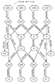
生成部106は、変換部104が変換した図6~図8の各要素を組み合わせることにより、図9に示すグラフデータベース30を生成する。
以上説明したように、本実施形態によれば、部品の仕様および要件の情報テーブルを複数準備し、各テーブルが示す関係をテーブル別にグラフデータベース30の要素に変換し、変換後の要素を組み合わせることでグラフデータベース30を生成することができる。
設計情報をグラフデータベース化することで、例えば、所望の仕様を有する製品を構成する部品を高速に効率良く検索することができる。
設計情報をグラフデータベース化することで、例えば、所望の仕様を有する製品を構成する部品を高速に効率良く検索することができる。
また、部品別にテーブル10を準備するので、製品の一部仕様変更により部品が変更されたり、部品の仕様が変更されたりした場合でも、変更された部品のテーブル10のみを変更して、グラフデータベース30を生成し直せばよいので、変更による影響が小さい。また、変更に伴う確認は変更された部品のテーブル10のみでよいので、作業負荷が少なく、ミスも低減できる。
また、複雑な仕様の多数の部品からなる製品を検索する場合にも、テーブル10を準備してグラフデータベース30を生成するだけでよいので、効率がよく、また、ミスを低減できる。
(第2の実施の形態)
図10は、本発明の実施の形態に係る情報処理装置100の論理的な構成を示す機能ブロック図である。図10の情報処理装置100は、図1の上記実施形態の構成に加え、さらに、表示制御部110を備えている。図10は、図1の構成との組み合わせた例を示しているが、他の実施形態の構成と組み合わせてもよい。本実施形態の情報処理装置100は、図1の上記実施形態で生成されたグラフデータベース30を再評価し、グラフデータベース30を表示する構成を有する点以外は、上記実施形態と同様である。
図10は、本発明の実施の形態に係る情報処理装置100の論理的な構成を示す機能ブロック図である。図10の情報処理装置100は、図1の上記実施形態の構成に加え、さらに、表示制御部110を備えている。図10は、図1の構成との組み合わせた例を示しているが、他の実施形態の構成と組み合わせてもよい。本実施形態の情報処理装置100は、図1の上記実施形態で生成されたグラフデータベース30を再評価し、グラフデータベース30を表示する構成を有する点以外は、上記実施形態と同様である。
表示制御部110は、生成されたグラフデータベース30において、ある項目が選択されると、当該項目につながっている他の項目及びそのつながりを識別可能にコンピュータ80の表示装置92に表示させる。
ここで、項目とは、例えば、図9のグラフデータベース30を例にとると、部品(A1、A2、B1、B2、C1~C3)、仕様(X1、X2、Y1、Y2)、および、製品(VAR1~VAR4)の少なくともいずれか1つである。
例えば、表示制御部110は、図9のグラフデータベース30を描画した画面を表示装置92に表示し、入力装置94を用いた操作者による、ある項目の選択操作を受け付けることができる。
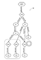
表示制御部110は、操作者により、ある製品バリエーションVAR1が選択されると、図11のようなグラフ38を描画した画面を表示してもよい。あるいは、図11の途中経過は表示せずに、生成部106が以下の再評価処理を行った後、検索結果として図12に示す最終的なグラフ38を描画した画面のみを表示制御部110が表示してもよい。
以下、4つの製品バリエーションのうち、製品バリエーションVAR1について、再評価を行う手順を説明する。図9のグラフデータベース30から、製品バリエーションVAR1のグラフ38のみを取り出すと、図11に示すようになる。図11は、選択された製品バリエーションVAR1につながっている他の項目と、そのつながりを示している。
ここで、図中、製品バリエーションVAR1のグラフ38中の3つの論理演算子ANDについて、部品Cが必要とする部品Aと仕様Yとの条件が定義されていないものが含まれている(図中、破線で囲んだ部分)。
このように定義されていないものが含まれる理由は、例えば、図7に示した部品C2の必要条件である部品A1および仕様Y2のうち、仕様Y2は図11のグラフ38に含まれていないために、部品C2の条件が不足するのである。また、図7で示して部品C3の必要条件である部品A2および仕様Y1のうち、部品A2は図11のグラフ38に含まれていないために、部品C3の条件が不足するのである。このようにして、条件が不足している部品C2および部品C3の経路が除外される。
このようにして図12に示す要素がグラフ38に残る。この最終的なグラフ38は、製品バリエーションVAR1の仕様X1とY1とを満たす部品の組み合わせが、A1かつB1かつC1であることを示している(図中、矢印が指し示している部品)。生成部106により再評価して得られたグラフ38を表示制御部110が表示する。
このように、本実施形態の情報処理装置100によれば、ある製品のある仕様を満たすための必要条件を効率よく求めることができる。
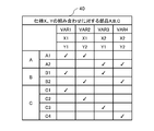
このようにして得られた結果は、例えば、図13のテーブル40として表示制御部110により出力されてよい。テーブル40は、表示されてもよいし、データファイルとして出力されてもよい。テーブル40は、仕様XとYとの組み合わせに対する部品A、B、Cの組み合わせを示している。言い換えると、テーブル40は、どの部品を組み合わせれば、各仕様(X、Y)の組み合わせを有するいずれの製品(VAR1~VAR4)を実現できるかを示している。
また、情報処理装置100は、変換部104および生成部106におけるテーブル10を基に処理を行う過程で、経路がつながらない等のエラーを検出する検出部(不図示)をさらに備えてもよい。これにより、設計ミス等による設計仕様や条件自体の間違いや、テーブル10作成時の入力ミス等を検出することができる。
具体的には、検出部は、「ある部品が選択される条件が存在しない(例えば、VAR1~VAR4のどのバリエーションでも部品C1が選択されない)」、あるいは、「ある条件で選択される部品が複数存在する(VAR1の条件で、部品C1とC2の両方が選択される)」といったケースを検出する。ただし、色が異なるだけで機能は同じ部品がある場合は、ある条件で複数の部品が選択される場合もあり、そのような場合にはエラーとはしない。
検出部は、エラーが検出されたテーブル10の情報を操作者に通知してもよい。エラーが検出されたテーブル10のデータファイルの情報(ファイル名やパス情報)を通知してもよいし、さらに、エラーが検出された経路に関連している要素に対応するテーブル10内の項目をハイライト表示してもよい。あるいは、図9のグラフデータベース30の画面で、経路がつながらなかった箇所を点滅表示する等して通知してもよい。
以上説明したように、本実施形態によれば、グラフデータベース30において、ある項目が選択されると、選択された項目に関係する他の項目と、そのつながりが識別可能に表示されるので、多数の部品を組み合せて作製される製品であっても、見やすく直感的に分かりやすい画面とすることができる。また、複数の構成案のバリエーションの中から、幾つかの案を選択して表示することで、比較評価することもできる。
また、設計ミス等によりテーブル10に間違いがあった場合にエラーを検出して通知することができるので、グラフデータベース30の精度を向上することができる。
(第3の実施の形態)
図14は、本発明の実施の形態に係る情報処理装置100の論理的な構成を示す機能ブロック図である。
本実施形態の情報処理装置100は、図10の上記実施形態の構成に加え、さらに、検索部120を備える。図14は、図10の構成との組み合わせた例を示しているが、他の実施形態の構成と組み合わせてもよい。
図14は、本発明の実施の形態に係る情報処理装置100の論理的な構成を示す機能ブロック図である。
本実施形態の情報処理装置100は、図10の上記実施形態の構成に加え、さらに、検索部120を備える。図14は、図10の構成との組み合わせた例を示しているが、他の実施形態の構成と組み合わせてもよい。
上記実施形態では、ノード32間の経路を辿り、製品のバリエーションを検索して取得する例を示した。しかし、実際の製品は、多数の部品から構成されていたり、仕様が多岐にわたっていたり、部品や仕様間の関係に制約があったりする。そのため、グラフデータベース30の構造が複雑になったり、検索対象の組み合わせが莫大になったりして、検索速度が低下し効率が悪くなる。そこで、本実施形態では、グラフデータベース30のノード32間の経路を辿るのではなく、はじめに、部品又は仕様の間の関係性を検索することで、項目レベルで検索経路を取得し、その後、取得された検索経路上で検索条件を満たすノードを検索する構成を有するものとする。
グラフデータベース30において、リレーション34は方向性が定義されている。
検索部120は、グラフデータベース30のリレーション34の方向に関係なく複数の項目間のつながりを検索する。また、検索部120は、項目間の関係とその方向性とを示す関係データを生成し、生成した関係データをグラフデータベース30に追加する。
検索部120は、グラフデータベース30のリレーション34の方向に関係なく複数の項目間のつながりを検索する。また、検索部120は、項目間の関係とその方向性とを示す関係データを生成し、生成した関係データをグラフデータベース30に追加する。
図15は、検索部120の処理手順の一例を示すフローチャートである。
検索部120は、指定された検索条件を満たすノード32の組み合わせを検索する。
ここでは、情報処理装置100を、製品であるパーソナルコンピュータの構成および仕様を決定するコンフィギュレーターとして機能させる場合を例に説明する。
まず、検索部120は、テーブル10の第1の情報および第2の情報に対応する項目間の関係と、当該項目間の関係の方向を取得する(ステップS201)。
検索部120は、指定された検索条件を満たすノード32の組み合わせを検索する。
ここでは、情報処理装置100を、製品であるパーソナルコンピュータの構成および仕様を決定するコンフィギュレーターとして機能させる場合を例に説明する。
まず、検索部120は、テーブル10の第1の情報および第2の情報に対応する項目間の関係と、当該項目間の関係の方向を取得する(ステップS201)。
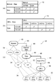
図16は、2つのテーブル10を用いてグラフデータベース30に関係データを追加する例を説明するための図である。図16(a)は、パーソナルコンピュータの販売市場(図中、「Market」と示す)(JAPANとUSA)と、液晶ディスプレイのサイズ(13インチと15インチ)との関係を示すテーブル10を示している。図16(b)は、パーソナルコンピュータの液晶ディスプレイのサイズ(図中、「Size」と示す)(13インチと15インチ)とCPUの性能(2.3GHz、2.5GHz、2.8GHz、2.9GHz)との関係を示すテーブル10を示している。
図16(c)は、関係データを説明するための図である。
図16(c)では、グラフデータベース30のノード32を、それぞれ対応する項目でグループ化して上位の項目ノード42として追加するとともに、さらに、項目ノード42間の関係44(以後、「項目間の関係44」とも呼ぶ)を示す表示が追加されている。グラフデータベース30のノード32間の関係(リレーション34)は破線の矢印で示してある。項目間の関係44は、実線の矢印で示されるように、テーブル10の定義に従った方向46を有している。なお、リレーション34と関係44とは、破線や実線に限定されず、互いに識別可能な態様で表示されていればよい。
図16(c)では、グラフデータベース30のノード32を、それぞれ対応する項目でグループ化して上位の項目ノード42として追加するとともに、さらに、項目ノード42間の関係44(以後、「項目間の関係44」とも呼ぶ)を示す表示が追加されている。グラフデータベース30のノード32間の関係(リレーション34)は破線の矢印で示してある。項目間の関係44は、実線の矢印で示されるように、テーブル10の定義に従った方向46を有している。なお、リレーション34と関係44とは、破線や実線に限定されず、互いに識別可能な態様で表示されていればよい。
このように、関係データとは、グラフデータベース30に追加される、項目ノード42、項目間の関係44、および項目間の方向46を示す矢印である。生成部106は、これら関係データをグラフデータベース30に追加する。このとき、生成部106は、ノード32間のリレーション34の方向に、項目間の関係44の方向を揃えてグラフデータベース30に登録する。ここで、項目間の方向とは、項目の必要十分条件の関係を示していて、項目Aならば項目B(つまり、項目Bは項目Aの必要条件、あるいは、項目Aは項目Bの十分条件)の場合、矢印は項目A→項目Bの方向を指すものとする。
表示制御部110は、図16(c)のグラフデータベース30を表示してもよい。図16(c)のグラフデータベース30の要素のうち、各項目のノード32は非表示にして、項目ノード42のみが表示されてもよい。あるいは、項目ノード42を選択するとその直下のノード32が表示又は非表示に切り替わってもよい。
表示制御部110は、追加された関係データを、オリジナルのグラフデータベース30の要素とは識別可能に、形状、色、表示形態(ハイライト、ブリンク、アニメーション等)を変えて表示してもよい。
なお、項目間の関係44は、必ずしも定義する必要はなく、項目ノード42と、項目ノード42間を連結するリレーション46だけの定義とすることもできる。
そして、検索部120は、取得した項目間の関係44とその方向とに基づいて、項目ノード42間の検索経路を定義する(図15のステップS203)。
図17は、検索経路と、受け付けた検索条件と、検索結果の一例を示す図である。
図17(a)の1行目に示される検索経路には、項目ノード42(n1、n2、n3)と、項目間の関係44とが定義されている。破線で囲まれた部分47の矢印の向きが、関係44の方向を示している。
上記したように、検索部120は、まず、グラフデータベース30に登録されている項目ノード42と項目間の関係44に基づいて、検索経路を検索する。図17(a)に示すように、検索経路は、項目間の関係44の方向を含んで定義される。
図17(a)の1行目に示される検索経路には、項目ノード42(n1、n2、n3)と、項目間の関係44とが定義されている。破線で囲まれた部分47の矢印の向きが、関係44の方向を示している。
上記したように、検索部120は、まず、グラフデータベース30に登録されている項目ノード42と項目間の関係44に基づいて、検索経路を検索する。図17(a)に示すように、検索経路は、項目間の関係44の方向を含んで定義される。
そして、検索部120は、検索条件を受け付け(図15のステップS205)、定義した検索経路に従って、検索条件を満たすグラフデータベース30のノード32の組み合わせを検索する(図15のステップS207)。
ここで、検索部120は、項目間の関係44の方向に基づいて、複数のノード32間のリレーション34の方向を特定することができるので、検索経路の項目間の関係44の方向に関係なく経路に沿って検索を行うことができる。言い換えると、項目間の関係44の方向として、経路に沿った順方向とその逆の方向とをそれぞれ含んだ検索経路であっても、項目間の関係44の方向に基づいてリレーション34の方向を特定できるので、経路に沿ってノード32の検索を行うことができることとなる。
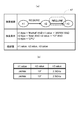
図17(a)の2行目以降は、検索条件が指定されている。ここでは、市場(JAPAN)と液晶ディスプレイのサイズ(13インチ)が指定された場合の、CPUが取り得る値を検索するための検索条件が指定されている。そして、検索結果として、各ノード32の値を返すことが指定されている。
図中、「ni.type」(iを自然数)は、ノードniの仕様種別を示し、「ni.value」は、ノードniの仕様値を示している。
そして、検索部120は、各ノード32の値を検索結果として出力する(図15のステップS209)。
図17(b)は、図17(a)の検索経路に従って検索した結果の出力例を示す図である。
検索部120による検索結果は、表示制御部110により図17(b)の画面として表示される。または、検索結果は、データファイルとして出力されてもよい。
図17(b)は、図17(a)の検索経路に従って検索した結果の出力例を示す図である。
検索部120による検索結果は、表示制御部110により図17(b)の画面として表示される。または、検索結果は、データファイルとして出力されてもよい。
このように、定義された方向に関係なく、経路上の各項目の複数のノード32のうち、検索条件を満たすノード32が抽出され、抽出された各項目のノード32の値が検索結果として取得される。
以下、方向に関係なく経路に沿って検索を行う場合について、図18~図19を用いて具体的に説明する。
図18(a)のテーブル10は、図16(a)と同じである。図18(b)のテーブル10は、図16(b)とは液晶ディスプレイとCPUとの関係を示すテーブル10の項目間の関係が逆になっている。
図18(a)のテーブル10は、図16(a)と同じである。図18(b)のテーブル10は、図16(b)とは液晶ディスプレイとCPUとの関係を示すテーブル10の項目間の関係が逆になっている。
そして、これらのテーブル10から定義される検索経路は、図19(a)に示すように、破線で囲まれている部分47の項目間の関係44の矢印の向きが図17(a)と逆になっている。
検索部120は、図19(a)の2行目以降に定義されている検索条件に従って検索を行う。その際、検索部120は、検索経路で定義された経路に沿って、しかし、検索部120は、項目間の関係44の方向には関係なく、検索を行う。その結果取得される検索結果は、図19(b)のようになり、これは、図17(b)の検索結果と同じである。
次に、論理演算子が含まれる関係定義を含む場合について図20~図22を用いて説明する。
図20に示すように、テーブル10は、液晶ディスプレイのサイズ(13インチ、15インチ)とタッチバー(有無)と、ストレージ容量(128GB、256GB、512GB)との関係を示している。図20の「w/」は、タッチバーを有していることを示し、「w/o」は、タッチバーを有してないことを示している。
図20に示すように、テーブル10は、液晶ディスプレイのサイズ(13インチ、15インチ)とタッチバー(有無)と、ストレージ容量(128GB、256GB、512GB)との関係を示している。図20の「w/」は、タッチバーを有していることを示し、「w/o」は、タッチバーを有してないことを示している。
図20のように、論理演算子が含まれる関係定義を含むテーブル10の場合、図21に示すように、各項目ノード42間の関係44も、「Size x Touch Bar-Storage」と、論理演算子(論理積を示す「x」)を含んだラベルで示される。
このようなテーブル10により、複数の必要な条件(液晶ディスプレイのサイズとタッチバーの有無)に対するその答え(ストレージ容量)を絞り込んだ関係を定義できる。これにより、複雑な設計仕様もグラフデータベース30として定義することができる。
このようなテーブル10により、複数の必要な条件(液晶ディスプレイのサイズとタッチバーの有無)に対するその答え(ストレージ容量)を絞り込んだ関係を定義できる。これにより、複雑な設計仕様もグラフデータベース30として定義することができる。
図22(a)に示すように、検索経路として、2つの経路が定義される。そして指定された検索条件に従って、検索部120が経路に沿って検索を行う。そして、経路上の各項目の複数のノード32の中から、検索条件を満たすノード32が抽出され、抽出された各項ものノード32の値が検索結果として取得される。表示制御部110は、図22(b)の検索結果を表示する。
以上説明したように、本実施形態によれば、上記実施形態と同様な効果を奏するとともに、さらに、検索部120が、項目間の関係の方向に関係なく、検索を行うので、テーブル10の項目の関係の定義が逆になっていた場合でも、問題なく検索を行うことができる。さらに、本実施形態では、ノード32とリレーション34を辿るのではなく、ノード32をグループ化した項目ノード42と、項目間の関係44との経路を定義して、その経路上を辿りながら、検索条件を満たすノード32を検索するので、検索に係る時間を短縮でき、効率よく検索できる。
(第4の実施の形態)
本実施形態の情報処理装置100は、図14の情報処理装置100と同様な構成を有する。
本実施形態の情報処理装置100は、図14の情報処理装置100と同様な構成を有する。
本実施形態の情報処理装置100において、グラフデータベース30を生成する際、生成部106が使用するテーブル10は切り替え可能になっている。そして表示制御部110は、使用するテーブル10の選択を受け付け、選択されているテーブル10を用いて生成されたグラフデータベース30を表示する。言い換えると、生成部106が生成するグラフデータベース30は、選択されているテーブル10によって異なる。さらに、表示制御部110は、複数のテーブル10それぞれに基づいて生成されたグラフデータベース30を重ねて表示することもできる。
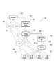
図23は、液晶ディスプレイのサイズとCPUの性能に関して異なる2つの設計仕様や設計条件に基づいた2つの第1のテーブル10aと第2のテーブル10bを示している。図24は、図23の第1のテーブル10aと第2のテーブル10bと、市場と液晶ディスプレイのサイズに関するテーブル10とを用いて生成されたグラフデータベース30を示す図である。
図24(b)に示すように、グラフデータベース30は、第1のテーブル10aに基づく関係44(Size-CPU #1)と第2のテーブル10bに基づく関係44(Size-CPU #2)との両方が含まれている。
表示制御部110は、図24(b)のグラフデータベース30を描画した画面を表示するとともに、表示されたグラフデータベース30の中の第1のテーブル10aに基づく関係44(Size-CPU #1)と第2のテーブル10bに基づく関係44(Size-CPU #2)とのうちの一方が操作者により選択されると、選択された関係44にのみ対応するグラフデータベース30を描画した画面(図25又は図26)を表示する。
テーブル10の選択(切替)方法は、様々考えられるが、例えば、まず、設計仕様毎に、識別情報と、テーブル10の組み合わせを対応付けて登録するとともに、設計仕様毎に生成されるグラフデータベース30にも当該識別情報を対応付けておく。そして、設計仕様の識別情報の指定を受け付けることで、指定された識別情報の設計仕様に対応するグラフデータベース30を呼び出すことができる。
また、設計仕様の識別情報に対応付けて登録されるテーブル10は、少なくとも異なる設計仕様間で切り替わるテーブル10を含んでいればよい。異なる設計仕様で共通しているテーブル10は共通情報として登録すればよい。
また、設計仕様の識別情報に対応付けて登録されるテーブル10は、少なくとも異なる設計仕様間で切り替わるテーブル10を含んでいればよい。異なる設計仕様で共通しているテーブル10は共通情報として登録すればよい。
図25は、第1のテーブル10aに基づく関係44(Size-CPU #1)が選択された場合のグラフデータベース30を描画した画面を示す図である。図26は、第2のテーブル10bに基づく関係44(Size-CPU #2)が選択された場合のグラフデータベース30を描画した画面を示す図である。
このように、表示制御部110は、設計仕様や設計条件が異なる複数のテーブル10を用いて生成されたグラフデータベース30において、選択された関係44に対応するテーブル10を判別し、当該テーブル10に対応するグラフ38のみを抽出して表示し、選択されなかった関係44に対応するテーブル10のグラフ38は非表示にする。あるいは、選択されなかった方は、表示色を薄くする等、選択されたものと区別可能に、かつ、選択されたものが優先的に見えるように、表示する。
また、表示制御部110は、図27のような画面200を表示してもよい。この画面200は、グラフデータベース30の項目ノード42と関係44とを階層的に表示している。言い換えると、ある項目ノード42に直接つながっている複数の項目ノード42と関係44とを、同一の行又は列となるように配置して表示している。
また、選択された階層のみを表示又は非表示にしたり、ある階層が選択されると、その階層の直下の階層が表示又は非表示にしてもよい。さらに、階層内の項目ノード42が選択されると、対応するノード32と、そのノード32に関連するノード32およびリレーション34が表示されてもよい。
以上説明したように、本実施形態によれば、設計仕様や設計条件が異なる複数のテーブル10を用いて生成されたグラフデータベース30において、異なる複数案の設計仕様や設計条件のテーブル10を用いてグラフデータベース30を生成しておき、仕様に合わせてテーブル10を選択してグラフデータベース30を切り替えて表示させることができる。よって、複数案を切り替えて評価しながら検討することが可能になる。
以上、図面を参照して本発明の実施形態について述べたが、これらは本発明の例示であり、上記以外の様々な構成を採用することもできる。
たとえば、情報処理装置100は、さらに、生成されたグラフデータベース30をコンピュータ80のストレージ85(又はメモリ84)に記憶する記憶部(不図示)をさらに備えてもよい。記憶部は、生成されたグラフデータベース30を各々、例えば、生成時刻または保存時刻、および、グラフデータベース30の生成に使用した複数のテーブル10の情報に紐付けて記憶することで、設計仕様や設計条件の変更履歴として管理することができる。また、生成されたグラフデータベース30は、異なる識別情報又は名前を付して記憶されてもよい。
たとえば、情報処理装置100は、さらに、生成されたグラフデータベース30をコンピュータ80のストレージ85(又はメモリ84)に記憶する記憶部(不図示)をさらに備えてもよい。記憶部は、生成されたグラフデータベース30を各々、例えば、生成時刻または保存時刻、および、グラフデータベース30の生成に使用した複数のテーブル10の情報に紐付けて記憶することで、設計仕様や設計条件の変更履歴として管理することができる。また、生成されたグラフデータベース30は、異なる識別情報又は名前を付して記憶されてもよい。
また、他の実施形態として、情報処理装置100は、設計仕様の一部が変更になることによる影響範囲の分析を行う構成を有してもよい。
情報処理装置100は、テーブル10の部品の仕様及び要件の少なくとも一部が変更されると、当該変更された部品の仕様及び要件に対応する項目を特定する特定部(不図示)をさらに備えてもよい。そして、表示制御部110は、特定された項目につながっている他の項目及びそのつながりを識別可能に、例えば、形状、色、表示形態(ハイライト、ブリンク、アニメーション等)を変えて表示する。
この構成によれば、特定の設計仕様が変更になった場合に、その影響範囲を識別可能に表示することができるので、影響範囲の分析を行うことができる。
情報処理装置100は、テーブル10の部品の仕様及び要件の少なくとも一部が変更されると、当該変更された部品の仕様及び要件に対応する項目を特定する特定部(不図示)をさらに備えてもよい。そして、表示制御部110は、特定された項目につながっている他の項目及びそのつながりを識別可能に、例えば、形状、色、表示形態(ハイライト、ブリンク、アニメーション等)を変えて表示する。
この構成によれば、特定の設計仕様が変更になった場合に、その影響範囲を識別可能に表示することができるので、影響範囲の分析を行うことができる。
設計仕様の変更の受け付け方法は、例えば、テーブル10を切り替えることでもよいし、変更となる設計仕様を示す仕様間の関係44を指示することでもよい。
また、特定された項目を用いる他の設計仕様が直接の影響範囲となり、さらに、直接の影響範囲で用いられる他の項目を用いる設計仕様が次の影響範囲となる。これを再帰的に繰り返すことによって、影響するすべての設計仕様を求めることができる。
表示制御部110は、直接の影響範囲と、それ以降の影響範囲をそれぞれ区別して識別可能に表示してもよい。また、影響される順に順次識別可能に表示してもよい。
表示制御部110は、直接の影響範囲と、それ以降の影響範囲をそれぞれ区別して識別可能に表示してもよい。また、影響される順に順次識別可能に表示してもよい。
図28は、図27のSize-Touch Barの設計仕様が変更された場合の、直接の影響範囲と、それ以降の影響範囲をそれぞれ区別して識別可能に表示した例を示している。ここでは、Touch Barがw/とw/oの2つの選択条件であったのを、w/(Large)、w/(Small)、w/oの3種類の選択条件に変更になったとする。そして、Touch Barが設計仕様に含まれるSize x Touch Bar-Graphics、Size x Touch Bar-Interface、Size x Touch Bar-Storageの3つの設計仕様に影響が及ぶことが示されている。図中、二重線が直接の影響範囲を示していて、一点鎖線がそれ以降の影響範囲を示しているが、上記したように、各影響範囲は、形状、色、表示形態(ハイライト、ブリンク、アニメーション等)を変えてそれぞれ表示される。これにより、Size x Touch Bar-Graphics、Size x Touch Bar-Interface、Size x Touch Bar-Storageの3つの設計仕様の変更が必要なことを操作者は認識することができる。また、Size-CPUが変更になった場合は、CPUの選択のみが変更され、他の設計仕様に影響はしない。この場合には、影響がないことを表示してもよい。
また、図29は、Size-Touch Barの設計仕様が変更され、Touch BarとSizeの組み合わせ条件が変更になった場合の例を示している。SizeとTouch Barの両方が設計仕様に含まれるSize x Touch Bar-Graphics、Size x Touch Bar-Interface、Size x Touch Bar-Storageの3つの設計仕様に影響が及ぶことが示されている。これにより、Size x Touch Bar-Graphics、Size x Touch Bar-Interface、Size x Touch Bar-Storageの3つの設計仕様の変更が必要なことを操作者は認識することができる。
以上、実施形態および実施例を参照して本願発明を説明したが、本願発明は上記実施形態および実施例に限定されるものではない。本願発明の構成や詳細には、本願発明のスコープ内で当業者が理解し得る様々な変更をすることができる。
なお、本発明において利用者に関する情報を取得、利用する場合は、これを適法に行うものとする。
なお、本発明において利用者に関する情報を取得、利用する場合は、これを適法に行うものとする。
以下、参考形態の例を付記する。
1. コンピュータに、
複数の部品別に定義されたテーブルであって、当該部品の仕様及び要件の一方の少なくとも一部である第1の情報と、当該部品の仕様及び要件の一方の少なくとも一部であり前記第1の情報とは異なる第2の情報と、の関係を示すテーブルを複数取得する手順、
あるテーブルにおける前記第2の情報は、他のテーブルの前記第1の情報の少なくとも一部であり、
複数の前記テーブルのそれぞれが示す前記関係を前記テーブル別にグラフデータベースの要素に変換する手順、
複数の前記テーブルの変換後の複数の前記要素を組み合わせることにより、前記グラフデータベースを生成する手順、
を実行させるためのプログラム。
2. 1.に記載のプログラムにおいて、
生成された前記グラフデータベースにおいて、ある項目が選択されると、当該項目につながっている他の項目及びそのつながりを識別可能に表示する手順をさらにコンピュータに実行させるためのプログラム。
3. 1.又は2.に記載のプログラムにおいて、
前記グラフデータベースにおいて、前記関係の方向性が定義されている、プログラム。
4. 1.又は2.に記載のプログラムにおいて、
前記グラフデータベースにおいて、前記関係の方向性が定義されており、
生成された前記グラフデータベースにおいて、検索条件が指定されると、前記関係の方向に関係なく複数の項目間のつながりを示す経路を検索する手順、
前記経路に沿って前記検索条件を満たす前記要素の組み合わせを検索する手順、をさらにコンピュータに実行させるためのプログラム。
5. 3.又は4.に記載のプログラムにおいて、
前記項目間の関係とその方向性を示す関係データを生成する手順、
生成した前記関係データを前記グラフデータベースに追加する手順、をコンピュータに実行させるためのプログラム。
6. 1.から5.のいずれか一つに記載のプログラムにおいて、
前記グラフデータベースを生成する際、使用する前記テーブルは切り替え可能であり、
選択されている前記テーブルを用いて生成された前記グラフデータベースを表示する手順、をさらにコンピュータに実行させるためのプログラム。
7. 1.から6.のいずれか一つに記載のプログラムにおいて、
ある項目に直接つながっている複数の項目を、同一の行又は列となるように配置して表示する手順をさらにコンピュータに実行させるためのプログラム。
8. 1.から7.のいずれか一つに記載のプログラムにおいて、
生成された前記グラフデータベースを、当該グラフデータベースを生成する際に使用した前記テーブルの情報を紐付けて記憶装置に記憶する手順をさらにコンピュータに実行させるためのプログラム。
9. 1.から8.のいずれか一つに記載のプログラムにおいて、
前記テーブルの前記部品の前記仕様及び前記要件の少なくとも一部が変更されると、当該変更された前記部品の前記仕様及び前記要件に対応する項目を特定する手順、
特定された前記項目につながっている他の項目及びそのつながりを識別可能に表示する手順、をさらにコンピュータに実行させるためのプログラム。
10. 複数の部品別に定義されたテーブルであって、当該部品の仕様及び要件の一方の少なくとも一部である第1の情報と、当該部品の仕様及び要件の一方の少なくとも一部であり前記第1の情報とは異なる第2の情報と、の関係を示すテーブルを複数取得するテーブル取得手段と、
あるテーブルにおける前記第2の情報は、他のテーブルの前記第1の情報の少なくとも一部であり、
複数の前記テーブルのそれぞれが示す前記関係を前記テーブル別にグラフデータベースの要素に変換する変換手段と、
複数の前記テーブルの変換後の複数の前記要素を組み合わせることにより、前記グラフデータベースを生成する生成手段と、
を備える情報処理装置。
11. 10.に記載の情報処理装置において、
生成された前記グラフデータベースにおいて、ある項目が選択されると、当該項目につながっている他の項目及びそのつながりを識別可能に表示する表示手段をさらに備える情報処理装置。
12. 10.又は11.に記載の情報処理装置において、
前記グラフデータベースにおいて、前記関係の方向性が定義されている、情報処理装置。
13. 10.又は11.に記載の情報処理装置において、
前記グラフデータベースにおいて、前記関係の方向性が定義されており、
生成された前記グラフデータベースにおいて、検索条件が指定されると、前記関係の方向に関係なく複数の項目間のつながりを示す経路を検索し、前記経路に沿って前記検索条件を満たす前記要素の組み合わせを検索する検索手段をさらに備える情報処理装置。
14. 12.又は13.に記載の情報処理装置において、
前記生成手段は、
前記項目間の関係とその方向性を示す関係データを生成し、
生成した前記関係データを前記グラフデータベースに追加する、情報処理装置。
15. 10.から14.のいずれか一つに記載の情報処理装置において、
前記生成手段は、前記グラフデータベースを生成する際、使用する前記テーブルを切り替え可能であり、
選択されている前記テーブルを用いて生成された前記グラフデータベースを表示する表示手段をさらに備える情報処理装置。
16. 10.から15.のいずれか一つに記載の情報処理装置において、
ある項目に直接つながっている複数の項目を、同一の行又は列となるように配置して表示する表示手段をさらに備える情報処理装置。
17. 10.から16.のいずれか一つに記載の情報処理装置において、
生成された前記グラフデータベースを、当該グラフデータベースを生成する際に使用した前記テーブルの情報を紐付けて記憶装置に記憶する手段をさらに備える情報処理装置。
18. 10.から17.のいずれか一つに記載の情報処理装置において、
前記テーブルの前記部品の前記仕様及び前記要件の少なくとも一部が変更されると、当該変更された前記部品の前記仕様及び前記要件に対応する項目を特定する特定手段をさらに備え、
前記表示手段は、
特定された前記項目につながっている他の項目及びそのつながりを識別可能に表示する、情報処理装置。
19. 情報処理装置が、
複数の部品別に定義されたテーブルであって、当該部品の仕様及び要件の一方の少なくとも一部である第1の情報と、当該部品の仕様及び要件の一方の少なくとも一部であり前記第1の情報とは異なる第2の情報と、の関係を示すテーブルを複数取得し、
あるテーブルにおける前記第2の情報は、他のテーブルの前記第1の情報の少なくとも一部であり、
複数の前記テーブルのそれぞれが示す前記関係を前記テーブル別にグラフデータベースの要素に変換し、
複数の前記テーブルの変換後の複数の前記要素を組み合わせることにより、前記グラフデータベースを生成する、情報処理方法。
20. 19.に記載の情報処理方法において、
前記情報処理装置が、
生成された前記グラフデータベースにおいて、ある項目が選択されると、当該項目につながっている他の項目及びそのつながりを識別可能に表示する、情報処理方法。
21. 19.又は20.に記載の情報処理方法において、
前記グラフデータベースにおいて、前記関係の方向性が定義されている、情報処理方法。
22. 19.又は20.に記載の情報処理方法において、
前記グラフデータベースにおいて、前記関係の方向性が定義されており、
前記情報処理装置が、
生成された前記グラフデータベースにおいて、検索条件が指定されると、前記関係の方向に関係なく複数の項目間のつながりを示す経路を検索し、
前記経路に沿って前記検索条件を満たす前記要素の組み合わせを検索する、情報処理方法。
23. 21.又は22.に記載の情報処理方法において、
前記情報処理装置が、
前記項目間の関係とその方向性を示す関係データを生成し、
生成した前記関係データを前記グラフデータベースに追加する、情報処理方法。
24. 19.から23.のいずれか一つに記載の情報処理方法において、
前記グラフデータベースを生成する際、使用する前記テーブルは切り替え可能であり、
前記情報処理装置が、
選択されている前記テーブルを用いて生成された前記グラフデータベースを表示する、情報処理方法。
25. 19.から24.のいずれか一つに記載の情報処理方法において、
前記情報処理装置が、
ある項目に直接つながっている複数の項目を、同一の行又は列となるように配置して表示する、情報処理方法。
26. 19.から25.のいずれか一つに記載の情報処理方法において、
前記情報処理装置が、
生成された前記グラフデータベースを、当該グラフデータベースを生成する際に使用した前記テーブルの情報を紐付けて記憶装置に記憶する、情報処理方法。
27. 19.から26.のいずれか一つに記載の情報処理方法において、
前記情報処理装置が、
前記テーブルの前記部品の前記仕様及び前記要件の少なくとも一部が変更されると、当該変更された前記部品の前記仕様及び前記要件に対応する項目を特定し、
特定された前記項目につながっている他の項目及びそのつながりを識別可能に表示する、情報処理方法。
1. コンピュータに、
複数の部品別に定義されたテーブルであって、当該部品の仕様及び要件の一方の少なくとも一部である第1の情報と、当該部品の仕様及び要件の一方の少なくとも一部であり前記第1の情報とは異なる第2の情報と、の関係を示すテーブルを複数取得する手順、
あるテーブルにおける前記第2の情報は、他のテーブルの前記第1の情報の少なくとも一部であり、
複数の前記テーブルのそれぞれが示す前記関係を前記テーブル別にグラフデータベースの要素に変換する手順、
複数の前記テーブルの変換後の複数の前記要素を組み合わせることにより、前記グラフデータベースを生成する手順、
を実行させるためのプログラム。
2. 1.に記載のプログラムにおいて、
生成された前記グラフデータベースにおいて、ある項目が選択されると、当該項目につながっている他の項目及びそのつながりを識別可能に表示する手順をさらにコンピュータに実行させるためのプログラム。
3. 1.又は2.に記載のプログラムにおいて、
前記グラフデータベースにおいて、前記関係の方向性が定義されている、プログラム。
4. 1.又は2.に記載のプログラムにおいて、
前記グラフデータベースにおいて、前記関係の方向性が定義されており、
生成された前記グラフデータベースにおいて、検索条件が指定されると、前記関係の方向に関係なく複数の項目間のつながりを示す経路を検索する手順、
前記経路に沿って前記検索条件を満たす前記要素の組み合わせを検索する手順、をさらにコンピュータに実行させるためのプログラム。
5. 3.又は4.に記載のプログラムにおいて、
前記項目間の関係とその方向性を示す関係データを生成する手順、
生成した前記関係データを前記グラフデータベースに追加する手順、をコンピュータに実行させるためのプログラム。
6. 1.から5.のいずれか一つに記載のプログラムにおいて、
前記グラフデータベースを生成する際、使用する前記テーブルは切り替え可能であり、
選択されている前記テーブルを用いて生成された前記グラフデータベースを表示する手順、をさらにコンピュータに実行させるためのプログラム。
7. 1.から6.のいずれか一つに記載のプログラムにおいて、
ある項目に直接つながっている複数の項目を、同一の行又は列となるように配置して表示する手順をさらにコンピュータに実行させるためのプログラム。
8. 1.から7.のいずれか一つに記載のプログラムにおいて、
生成された前記グラフデータベースを、当該グラフデータベースを生成する際に使用した前記テーブルの情報を紐付けて記憶装置に記憶する手順をさらにコンピュータに実行させるためのプログラム。
9. 1.から8.のいずれか一つに記載のプログラムにおいて、
前記テーブルの前記部品の前記仕様及び前記要件の少なくとも一部が変更されると、当該変更された前記部品の前記仕様及び前記要件に対応する項目を特定する手順、
特定された前記項目につながっている他の項目及びそのつながりを識別可能に表示する手順、をさらにコンピュータに実行させるためのプログラム。
10. 複数の部品別に定義されたテーブルであって、当該部品の仕様及び要件の一方の少なくとも一部である第1の情報と、当該部品の仕様及び要件の一方の少なくとも一部であり前記第1の情報とは異なる第2の情報と、の関係を示すテーブルを複数取得するテーブル取得手段と、
あるテーブルにおける前記第2の情報は、他のテーブルの前記第1の情報の少なくとも一部であり、
複数の前記テーブルのそれぞれが示す前記関係を前記テーブル別にグラフデータベースの要素に変換する変換手段と、
複数の前記テーブルの変換後の複数の前記要素を組み合わせることにより、前記グラフデータベースを生成する生成手段と、
を備える情報処理装置。
11. 10.に記載の情報処理装置において、
生成された前記グラフデータベースにおいて、ある項目が選択されると、当該項目につながっている他の項目及びそのつながりを識別可能に表示する表示手段をさらに備える情報処理装置。
12. 10.又は11.に記載の情報処理装置において、
前記グラフデータベースにおいて、前記関係の方向性が定義されている、情報処理装置。
13. 10.又は11.に記載の情報処理装置において、
前記グラフデータベースにおいて、前記関係の方向性が定義されており、
生成された前記グラフデータベースにおいて、検索条件が指定されると、前記関係の方向に関係なく複数の項目間のつながりを示す経路を検索し、前記経路に沿って前記検索条件を満たす前記要素の組み合わせを検索する検索手段をさらに備える情報処理装置。
14. 12.又は13.に記載の情報処理装置において、
前記生成手段は、
前記項目間の関係とその方向性を示す関係データを生成し、
生成した前記関係データを前記グラフデータベースに追加する、情報処理装置。
15. 10.から14.のいずれか一つに記載の情報処理装置において、
前記生成手段は、前記グラフデータベースを生成する際、使用する前記テーブルを切り替え可能であり、
選択されている前記テーブルを用いて生成された前記グラフデータベースを表示する表示手段をさらに備える情報処理装置。
16. 10.から15.のいずれか一つに記載の情報処理装置において、
ある項目に直接つながっている複数の項目を、同一の行又は列となるように配置して表示する表示手段をさらに備える情報処理装置。
17. 10.から16.のいずれか一つに記載の情報処理装置において、
生成された前記グラフデータベースを、当該グラフデータベースを生成する際に使用した前記テーブルの情報を紐付けて記憶装置に記憶する手段をさらに備える情報処理装置。
18. 10.から17.のいずれか一つに記載の情報処理装置において、
前記テーブルの前記部品の前記仕様及び前記要件の少なくとも一部が変更されると、当該変更された前記部品の前記仕様及び前記要件に対応する項目を特定する特定手段をさらに備え、
前記表示手段は、
特定された前記項目につながっている他の項目及びそのつながりを識別可能に表示する、情報処理装置。
19. 情報処理装置が、
複数の部品別に定義されたテーブルであって、当該部品の仕様及び要件の一方の少なくとも一部である第1の情報と、当該部品の仕様及び要件の一方の少なくとも一部であり前記第1の情報とは異なる第2の情報と、の関係を示すテーブルを複数取得し、
あるテーブルにおける前記第2の情報は、他のテーブルの前記第1の情報の少なくとも一部であり、
複数の前記テーブルのそれぞれが示す前記関係を前記テーブル別にグラフデータベースの要素に変換し、
複数の前記テーブルの変換後の複数の前記要素を組み合わせることにより、前記グラフデータベースを生成する、情報処理方法。
20. 19.に記載の情報処理方法において、
前記情報処理装置が、
生成された前記グラフデータベースにおいて、ある項目が選択されると、当該項目につながっている他の項目及びそのつながりを識別可能に表示する、情報処理方法。
21. 19.又は20.に記載の情報処理方法において、
前記グラフデータベースにおいて、前記関係の方向性が定義されている、情報処理方法。
22. 19.又は20.に記載の情報処理方法において、
前記グラフデータベースにおいて、前記関係の方向性が定義されており、
前記情報処理装置が、
生成された前記グラフデータベースにおいて、検索条件が指定されると、前記関係の方向に関係なく複数の項目間のつながりを示す経路を検索し、
前記経路に沿って前記検索条件を満たす前記要素の組み合わせを検索する、情報処理方法。
23. 21.又は22.に記載の情報処理方法において、
前記情報処理装置が、
前記項目間の関係とその方向性を示す関係データを生成し、
生成した前記関係データを前記グラフデータベースに追加する、情報処理方法。
24. 19.から23.のいずれか一つに記載の情報処理方法において、
前記グラフデータベースを生成する際、使用する前記テーブルは切り替え可能であり、
前記情報処理装置が、
選択されている前記テーブルを用いて生成された前記グラフデータベースを表示する、情報処理方法。
25. 19.から24.のいずれか一つに記載の情報処理方法において、
前記情報処理装置が、
ある項目に直接つながっている複数の項目を、同一の行又は列となるように配置して表示する、情報処理方法。
26. 19.から25.のいずれか一つに記載の情報処理方法において、
前記情報処理装置が、
生成された前記グラフデータベースを、当該グラフデータベースを生成する際に使用した前記テーブルの情報を紐付けて記憶装置に記憶する、情報処理方法。
27. 19.から26.のいずれか一つに記載の情報処理方法において、
前記情報処理装置が、
前記テーブルの前記部品の前記仕様及び前記要件の少なくとも一部が変更されると、当該変更された前記部品の前記仕様及び前記要件に対応する項目を特定し、
特定された前記項目につながっている他の項目及びそのつながりを識別可能に表示する、情報処理方法。
この出願は、2018年12月10日に出願された日本出願特願2018-230949号を基礎とする優先権を主張し、その開示の全てをここに取り込む。
Claims (27)
- コンピュータに、
複数の部品別に定義されたテーブルであって、当該部品の仕様及び要件の一方の少なくとも一部である第1の情報と、当該部品の仕様及び要件の一方の少なくとも一部であり前記第1の情報とは異なる第2の情報と、の関係を示すテーブルを複数取得する手順、
あるテーブルにおける前記第2の情報は、他のテーブルの前記第1の情報の少なくとも一部であり、
複数の前記テーブルのそれぞれが示す前記関係を前記テーブル別にグラフデータベースの要素に変換する手順、
複数の前記テーブルの変換後の複数の前記要素を組み合わせることにより、前記グラフデータベースを生成する手順、
を実行させるためのプログラム。 - 請求項1に記載のプログラムにおいて、
生成された前記グラフデータベースにおいて、ある項目が選択されると、当該項目につながっている他の項目及びそのつながりを識別可能に表示する手順をさらにコンピュータに実行させるためのプログラム。 - 請求項1又は2に記載のプログラムにおいて、
前記グラフデータベースにおいて、前記関係の方向性が定義されている、プログラム。 - 請求項1又は2に記載のプログラムにおいて、
前記グラフデータベースにおいて、前記関係の方向性が定義されており、
生成された前記グラフデータベースにおいて、検索条件が指定されると、前記関係の方向に関係なく複数の項目間のつながりを示す経路を検索する手順、
前記経路に沿って前記検索条件を満たす前記要素の組み合わせを検索する手順、をさらにコンピュータに実行させるためのプログラム。 - 請求項3又は4に記載のプログラムにおいて、
前記項目間の関係とその方向性を示す関係データを生成する手順、
生成した前記関係データを前記グラフデータベースに追加する手順、をコンピュータに実行させるためのプログラム。 - 請求項1から5のいずれか一項に記載のプログラムにおいて、
前記グラフデータベースを生成する際、使用する前記テーブルは切り替え可能であり、
選択されている前記テーブルを用いて生成された前記グラフデータベースを表示する手順、をさらにコンピュータに実行させるためのプログラム。 - 請求項1から6のいずれか一項に記載のプログラムにおいて、
ある項目に直接つながっている複数の項目を、同一の行又は列となるように配置して表示する手順をさらにコンピュータに実行させるためのプログラム。 - 請求項1から7のいずれか一項に記載のプログラムにおいて、
生成された前記グラフデータベースを、当該グラフデータベースを生成する際に使用した前記テーブルの情報を紐付けて記憶装置に記憶する手順をさらにコンピュータに実行させるためのプログラム。 - 請求項1から8のいずれか一項に記載のプログラムにおいて、
前記テーブルの前記部品の前記仕様及び前記要件の少なくとも一部が変更されると、当該変更された前記部品の前記仕様及び前記要件に対応する項目を特定する手順、
特定された前記項目につながっている他の項目及びそのつながりを識別可能に表示する手順、をさらにコンピュータに実行させるためのプログラム。 - 複数の部品別に定義されたテーブルであって、当該部品の仕様及び要件の一方の少なくとも一部である第1の情報と、当該部品の仕様及び要件の一方の少なくとも一部であり前記第1の情報とは異なる第2の情報と、の関係を示すテーブルを複数取得するテーブル取得手段と、
あるテーブルにおける前記第2の情報は、他のテーブルの前記第1の情報の少なくとも一部であり、
複数の前記テーブルのそれぞれが示す前記関係を前記テーブル別にグラフデータベースの要素に変換する変換手段と、
複数の前記テーブルの変換後の複数の前記要素を組み合わせることにより、前記グラフデータベースを生成する生成手段と、
を備える情報処理装置。 - 請求項10に記載の情報処理装置において、
生成された前記グラフデータベースにおいて、ある項目が選択されると、当該項目につながっている他の項目及びそのつながりを識別可能に表示する表示手段をさらに備える情報処理装置。 - 請求項10又は11に記載の情報処理装置において、
前記グラフデータベースにおいて、前記関係の方向性が定義されている、情報処理装置。 - 請求項10又は11に記載の情報処理装置において、
前記グラフデータベースにおいて、前記関係の方向性が定義されており、
生成された前記グラフデータベースにおいて、検索条件が指定されると、前記関係の方向に関係なく複数の項目間のつながりを示す経路を検索し、前記経路に沿って前記検索条件を満たす前記要素の組み合わせを検索する検索手段をさらに備える情報処理装置。 - 請求項12又は13に記載の情報処理装置において、
前記生成手段は、
前記項目間の関係とその方向性を示す関係データを生成し、
生成した前記関係データを前記グラフデータベースに追加する、情報処理装置。 - 請求項10から14のいずれか一項に記載の情報処理装置において、
前記生成手段は、前記グラフデータベースを生成する際、使用する前記テーブルを切り替え可能であり、
選択されている前記テーブルを用いて生成された前記グラフデータベースを表示する表示手段をさらに備える情報処理装置。 - 請求項10から15のいずれか一項に記載の情報処理装置において、
ある項目に直接つながっている複数の項目を、同一の行又は列となるように配置して表示する表示手段をさらに備える情報処理装置。 - 請求項10から16のいずれか一項に記載の情報処理装置において、
生成された前記グラフデータベースを、当該グラフデータベースを生成する際に使用した前記テーブルの情報を紐付けて記憶装置に記憶する手段をさらに備える情報処理装置。 - 請求項10から17のいずれか一項に記載の情報処理装置において、
前記テーブルの前記部品の前記仕様及び前記要件の少なくとも一部が変更されると、当該変更された前記部品の前記仕様及び前記要件に対応する項目を特定する特定手段をさらに備え、
前記表示手段は、
特定された前記項目につながっている他の項目及びそのつながりを識別可能に表示する、情報処理装置。 - 情報処理装置が、
複数の部品別に定義されたテーブルであって、当該部品の仕様及び要件の一方の少なくとも一部である第1の情報と、当該部品の仕様及び要件の一方の少なくとも一部であり前記第1の情報とは異なる第2の情報と、の関係を示すテーブルを複数取得し、
あるテーブルにおける前記第2の情報は、他のテーブルの前記第1の情報の少なくとも一部であり、
複数の前記テーブルのそれぞれが示す前記関係を前記テーブル別にグラフデータベースの要素に変換し、
複数の前記テーブルの変換後の複数の前記要素を組み合わせることにより、前記グラフデータベースを生成する、情報処理方法。 - 請求項19に記載の情報処理方法において、
前記情報処理装置が、
生成された前記グラフデータベースにおいて、ある項目が選択されると、当該項目につながっている他の項目及びそのつながりを識別可能に表示する、情報処理方法。 - 請求項19又は20に記載の情報処理方法において、
前記グラフデータベースにおいて、前記関係の方向性が定義されている、情報処理方法。 - 請求項19又は20に記載の情報処理方法において、
前記グラフデータベースにおいて、前記関係の方向性が定義されており、
前記情報処理装置が、
生成された前記グラフデータベースにおいて、検索条件が指定されると、前記関係の方向に関係なく複数の項目間のつながりを示す経路を検索し、
前記経路に沿って前記検索条件を満たす前記要素の組み合わせを検索する、情報処理方法。 - 請求項21又は22に記載の情報処理方法において、
前記情報処理装置が、
前記項目間の関係とその方向性を示す関係データを生成し、
生成した前記関係データを前記グラフデータベースに追加する、情報処理方法。 - 請求項19から23のいずれか一項に記載の情報処理方法において、
前記グラフデータベースを生成する際、使用する前記テーブルは切り替え可能であり、
前記情報処理装置が、
選択されている前記テーブルを用いて生成された前記グラフデータベースを表示する、情報処理方法。 - 請求項19から24のいずれか一項に記載の情報処理方法において、
前記情報処理装置が、
ある項目に直接つながっている複数の項目を、同一の行又は列となるように配置して表示する、情報処理方法。 - 請求項19から25のいずれか一項に記載の情報処理方法において、
前記情報処理装置が、
生成された前記グラフデータベースを、当該グラフデータベースを生成する際に使用した前記テーブルの情報を紐付けて記憶装置に記憶する、情報処理方法。 - 請求項19から26のいずれか一項に記載の情報処理方法において、
前記情報処理装置が、
前記テーブルの前記部品の前記仕様及び前記要件の少なくとも一部が変更されると、当該変更された前記部品の前記仕様及び前記要件に対応する項目を特定し、
特定された前記項目につながっている他の項目及びそのつながりを識別可能に表示する、情報処理方法。
Priority Applications (1)
| Application Number | Priority Date | Filing Date | Title |
|---|---|---|---|
| JP2020560093A JP7211661B2 (ja) | 2018-12-10 | 2019-12-09 | 情報処理装置、情報処理方法、およびプログラム |
Applications Claiming Priority (2)
| Application Number | Priority Date | Filing Date | Title |
|---|---|---|---|
| JP2018230949 | 2018-12-10 | ||
| JP2018-230949 | 2018-12-10 |
Publications (1)
| Publication Number | Publication Date |
|---|---|
| WO2020122004A1 true WO2020122004A1 (ja) | 2020-06-18 |
Family
ID=71076445
Family Applications (1)
| Application Number | Title | Priority Date | Filing Date |
|---|---|---|---|
| PCT/JP2019/048047 Ceased WO2020122004A1 (ja) | 2018-12-10 | 2019-12-09 | 情報処理装置、情報処理方法、およびプログラム |
Country Status (2)
| Country | Link |
|---|---|
| JP (1) | JP7211661B2 (ja) |
| WO (1) | WO2020122004A1 (ja) |
Cited By (1)
| Publication number | Priority date | Publication date | Assignee | Title |
|---|---|---|---|---|
| WO2023017757A1 (ja) * | 2021-08-11 | 2023-02-16 | 長瀬産業株式会社 | グラフ処理装置、グラフ処理システム及びグラフ処理方法 |
Citations (3)
| Publication number | Priority date | Publication date | Assignee | Title |
|---|---|---|---|---|
| JP2010244150A (ja) * | 2009-04-02 | 2010-10-28 | Mitsubishi Electric Corp | 図面管理装置 |
| JP2014010812A (ja) * | 2012-07-03 | 2014-01-20 | Toshiba Corp | 情報処理装置、情報提供装置、情報システム及び情報処理プログラム |
| JP2014106719A (ja) * | 2012-11-27 | 2014-06-09 | Toshiba Corp | 影響関係解析装置 |
-
2019
- 2019-12-09 WO PCT/JP2019/048047 patent/WO2020122004A1/ja not_active Ceased
- 2019-12-09 JP JP2020560093A patent/JP7211661B2/ja active Active
Patent Citations (3)
| Publication number | Priority date | Publication date | Assignee | Title |
|---|---|---|---|---|
| JP2010244150A (ja) * | 2009-04-02 | 2010-10-28 | Mitsubishi Electric Corp | 図面管理装置 |
| JP2014010812A (ja) * | 2012-07-03 | 2014-01-20 | Toshiba Corp | 情報処理装置、情報提供装置、情報システム及び情報処理プログラム |
| JP2014106719A (ja) * | 2012-11-27 | 2014-06-09 | Toshiba Corp | 影響関係解析装置 |
Cited By (2)
| Publication number | Priority date | Publication date | Assignee | Title |
|---|---|---|---|---|
| WO2023017757A1 (ja) * | 2021-08-11 | 2023-02-16 | 長瀬産業株式会社 | グラフ処理装置、グラフ処理システム及びグラフ処理方法 |
| JP7278512B1 (ja) * | 2021-08-11 | 2023-05-19 | 長瀬産業株式会社 | グラフ処理装置、グラフ処理システム及びグラフ処理方法 |
Also Published As
| Publication number | Publication date |
|---|---|
| JP7211661B2 (ja) | 2023-01-24 |
| JPWO2020122004A1 (ja) | 2021-11-18 |
Similar Documents
| Publication | Publication Date | Title |
|---|---|---|
| Klarner et al. | PyBoolNet: a python package for the generation, analysis and visualization of boolean networks | |
| KR101805946B1 (ko) | 입-출력 예시를 사용한 텍스트 조작 프로그램 생성 | |
| US9542622B2 (en) | Framework for data extraction by examples | |
| US9466041B2 (en) | User selected flow graph modification | |
| US8234608B2 (en) | Circuit specification description visualizing device, circuit specification description visualizing method and storage medium | |
| JP5939588B2 (ja) | 関連ノードを探索する方法、並びに、そのコンピュータ、及びコンピュータ・プログラム | |
| KR102519868B1 (ko) | 다수 미디어 소스로부터의 콘텐츠의 조직화 및 시각화 | |
| WO2010045143A2 (en) | Automated development of data processing results | |
| Bakos | KNIME essentials | |
| Chisholm | Exploring data with Rapidminer | |
| Yalcinkaya et al. | Evaluating the usability aspects of construction operation building information exchange (COBie) standard | |
| US20130093771A1 (en) | Modified flow graph depiction | |
| US20130096967A1 (en) | Optimizer | |
| US20140136152A1 (en) | Analyzing hardware designs based on component re-use | |
| Edmunds et al. | Using constraint-satisfaction to optimise disassembly sequences generated from AND/OR information | |
| JP7211661B2 (ja) | 情報処理装置、情報処理方法、およびプログラム | |
| Ettorre et al. | Stunning doodle: A tool for joint visualization and analysis of knowledge graphs and graph embeddings | |
| JP2013012082A (ja) | テストデータ生成プログラム、テストデータ生成方法、テストデータ生成装置 | |
| Ekaputra et al. | An analysis framework for ontology querying tools | |
| KR101490697B1 (ko) | 시뮬레이션 데이터 기반의 동적 기능 메뉴를 제공하는 가시화 장치 및 이를 이용한 가시화 방법 | |
| Mota et al. | A compact timed state space approach for the analysis of manufacturing systems: key algorithmic improvements | |
| Nepal et al. | Solving the median shortest path problem in the planning and design of urban transportation networks using a vector labeling algorithm | |
| Stojmenovic | Listing combinatorial objects in parallel | |
| Javahery et al. | Pattern-based UI design: adding rigor with user and context variables | |
| JP5417359B2 (ja) | 文書評価支援システム、及び文書評価支援方法 |
Legal Events
| Date | Code | Title | Description |
|---|---|---|---|
| 121 | Ep: the epo has been informed by wipo that ep was designated in this application |
Ref document number: 19895145 Country of ref document: EP Kind code of ref document: A1 |
|
| ENP | Entry into the national phase |
Ref document number: 2020560093 Country of ref document: JP Kind code of ref document: A |
|
| NENP | Non-entry into the national phase |
Ref country code: DE |
|
| 122 | Ep: pct application non-entry in european phase |
Ref document number: 19895145 Country of ref document: EP Kind code of ref document: A1 |