WO2020121891A1 - スラット角固定具、その取り付け方法、ラダーコード通し器、採光装置及び採光システム - Google Patents
スラット角固定具、その取り付け方法、ラダーコード通し器、採光装置及び採光システム Download PDFInfo
- Publication number
- WO2020121891A1 WO2020121891A1 PCT/JP2019/047200 JP2019047200W WO2020121891A1 WO 2020121891 A1 WO2020121891 A1 WO 2020121891A1 JP 2019047200 W JP2019047200 W JP 2019047200W WO 2020121891 A1 WO2020121891 A1 WO 2020121891A1
- Authority
- WO
- WIPO (PCT)
- Prior art keywords
- ladder
- ladder cord
- slat
- angle fixing
- daylighting
- Prior art date
- Legal status (The legal status is an assumption and is not a legal conclusion. Google has not performed a legal analysis and makes no representation as to the accuracy of the status listed.)
- Ceased
Links
Images




Classifications
-
- E—FIXED CONSTRUCTIONS
- E06—DOORS, WINDOWS, SHUTTERS, OR ROLLER BLINDS IN GENERAL; LADDERS
- E06B—FIXED OR MOVABLE CLOSURES FOR OPENINGS IN BUILDINGS, VEHICLES, FENCES OR LIKE ENCLOSURES IN GENERAL, e.g. DOORS, WINDOWS, BLINDS, GATES
- E06B9/00—Screening or protective devices for wall or similar openings, with or without operating or securing mechanisms; Closures of similar construction
- E06B9/24—Screens or other constructions affording protection against light, especially against sunshine; Similar screens for privacy or appearance; Slat blinds
- E06B9/26—Lamellar or like blinds, e.g. venetian blinds
- E06B9/28—Lamellar or like blinds, e.g. venetian blinds with horizontal lamellae, e.g. non-liftable
- E06B9/30—Lamellar or like blinds, e.g. venetian blinds with horizontal lamellae, e.g. non-liftable liftable
- E06B9/303—Lamellar or like blinds, e.g. venetian blinds with horizontal lamellae, e.g. non-liftable liftable with ladder-tape
-
- E—FIXED CONSTRUCTIONS
- E06—DOORS, WINDOWS, SHUTTERS, OR ROLLER BLINDS IN GENERAL; LADDERS
- E06B—FIXED OR MOVABLE CLOSURES FOR OPENINGS IN BUILDINGS, VEHICLES, FENCES OR LIKE ENCLOSURES IN GENERAL, e.g. DOORS, WINDOWS, BLINDS, GATES
- E06B9/00—Screening or protective devices for wall or similar openings, with or without operating or securing mechanisms; Closures of similar construction
- E06B9/24—Screens or other constructions affording protection against light, especially against sunshine; Similar screens for privacy or appearance; Slat blinds
- E06B9/26—Lamellar or like blinds, e.g. venetian blinds
- E06B9/38—Other details
- E06B9/382—Details of ladder-tapes or ladder chains, e.g. buckles for local shortening of tapes
Definitions
- the present invention relates to a slat corner fixing device, a mounting method thereof, a ladder cord threading device, a lighting device, and a lighting system.
- the present application claims priority to Japanese Patent Application No. 2018-233376 filed in Japan on December 13, 2018, the contents of which are incorporated herein by reference.
- Patent Document 1 discloses a blind in which the slat angle can be adjusted in two stages, in which upper and lower dimming cords 3 and 4 for adjusting the angle of the slat 1 are provided with hit pieces 6 and 7, respectively.
- hooking pieces 8 and 9 are hooked on the lower ends of the hitting pieces 6 and 7 through the ring of the hitting pieces 6 and 7, and the indoor side and window side parts are provided in the upper part of the blind. It is attached to the light control cords 10 and 11.
- the slat angle can be adjusted for each part such as the upper part and the lower part of the blind. ..
- a plurality of dimming cords are not provided so that the slat angle can be adjusted for each part like the blind of Patent Document 1, and the slat angle is adjusted for each part. Can not.
- An aspect of the present invention is to provide a slat angle fixing tool or the like that can easily adjust the slat angle for each part even in the general blind as described above.
- a slat angle fixing tool is a ladder cord insertion hole into which a part of a predetermined position of at least one ladder cord for adjusting the angles of a plurality of slats of a solar radiation adjusting device is inserted, and a ladder cord. And a ladder cord holder that holds at least one ladder cord protruding from the insertion hole.
- a ladder cord threading device includes an operation unit that is operated by being gripped, an inverse action unit where a pair of knob hands intersect in the length direction and the width direction, and a plurality of slats of a solar radiation adjusting device. And a tip portion having a width when the ladder cord for adjusting the angle is pinched by a pair of knob hands, the width being the interval between the slats.
- a method for attaching a slat angle fixing device to a solar radiation adjusting device is to fix a part of a predetermined position of at least one ladder cord for adjusting the angles of a plurality of slats of the solar radiation adjusting device to the slat angle. At least one ladder cord protruding from the ladder cord insertion hole is held by the ladder cord holding portion of the slat corner fixing tool.
- a daylighting device includes a daylighting device that emits light that is incident in a predetermined direction, spacers that are respectively provided at both ends of a lower portion of a frame, and that secure a space into which a solar radiation adjusting device is placed, A ladder cord insertion portion into which a part of at least one ladder cord for adjusting the angles of the plurality of slats of the solar radiation adjusting device fixed by the spacer is inserted, and at least one ladder cord protruding from the ladder cord insertion portion. And a slat corner fixing tool having a ladder cord holding part for holding the slat angle holding part.
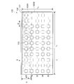
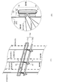
- FIG. 1 is a top perspective view showing a room to which a slat angle fixing device according to an aspect of the present invention is applied.
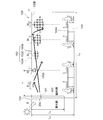
- FIG. 2 is a schematic sectional view taken along line II-II of FIG.
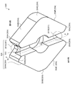
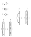
- FIG. 3 is a schematic view showing the configuration of the slat angle fixing tool according to the first embodiment.
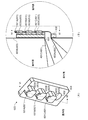
- FIG. 4 is a schematic sectional view taken along the line IV-IV of FIG.
- FIG. 5 is a schematic view showing the configuration of the slat angle fixing device according to the second embodiment.
- FIG. 6 is a schematic view showing the configuration of the slat angle fixing device according to the third embodiment.
- FIG. 7 is a schematic view showing the structure of the slat angle fixing tool according to the fourth embodiment.
- FIG. 1 is a top perspective view showing a room to which a slat angle fixing device according to an aspect of the present invention is applied.
- FIG. 2 is a schematic sectional view taken along line II-II of FIG.
- FIG. 8 is a schematic view showing the configuration of another slat angle fixing device according to the fourth embodiment.
- FIG. 9 is a schematic diagram showing the configuration of the daylighting device according to the fifth embodiment.
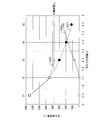
- FIG. 10 is a relationship diagram showing the relationship between the illuminance of a room to which the slat angle fixing device or the daylighting device according to an aspect of the present invention is applied and the distance from the panel.
- FIG. 11 is a schematic diagram showing the configuration of the ladder cord threading device.
- FIG. 1 is a top perspective view showing a room 100 to which a slat corner fixing device 300 described later according to an aspect of the present invention is applied.
- a panel 102 on which a daylighting plate 101 is installed is provided on a side portion of a room 100, and a ceiling 100B at an upper part inside the room 100 is arranged in a longitudinal direction and a lateral direction like columns S1 to S5.
- the indoor lighting devices 103 are provided side by side at intervals P in the direction.
- the panel 102 and the daylighting plate 101 are fixed to each other by fixing tools such as bolts and nuts that can be released.
- the panel 102 is, for example, a translucent plate-shaped glass or resin used for windows of buildings and vehicles.
- An area E of the ceiling 100B within a predetermined distance from the panel 102 is provided with a light-reflecting ceiling material 100A.
- the panel 102 is provided with, for example, a solar radiation adjusting device 400 in addition to the lighting plate 101.
- the angles of the slats 401 and 402 are adjusted by a ladder code 403 as described later.
- the solar radiation adjusting device 400 corresponds to a general blind or the like.
- the slat angle fixing device 300 is provided in the solar radiation adjusting device 400 at substantially the same position as the lower end of the daylighting plate 101, and the slat 401 and the slat 402 of the solar radiation adjusting device 400 have different angles with the slat angle fixing device 300 as a boundary. It is like this.
- a desk 104 is installed in the room 100, and the illuminance of a desk top surface 104A, which is the top surface of the desk 104, is measured when measuring the illuminance described later.
- the light-reflective ceiling material 100A preferably has diffuse reflectivity for brightening the room 100 (for example, the desk top surface 104A) and specular reflectivity for suppressing generation of glare light in the room 100.
- the light-reflective ceiling material 100A may be a material in which a metal plate having a specular reflectivity such as aluminum is embossed with irregularities of about several tens of ⁇ m so as to have a diffuse reflectivity.
- the light-reflective ceiling material 100A is a material in which a metal thin film such as aluminum having specular reflectivity is vapor-deposited on the surface of a resin plate which is embossed with unevenness of about several tens of ⁇ m so as to have diffuse reflectivity. Good.
- the unevenness due to embossing is preferably about several tens of ⁇ m, but the embossing may be formed on a curved surface with a period larger than several tens of ⁇ m.
- the shape of the embossing applied to the light-reflective ceiling material 100A is a stripe shape that extends toward the inner side of the room 100 (hereinafter, this may be referred to as the room or the room) (the shorter direction in FIG. 1).
- the light guided to the interior of the room and reflected by the light-reflecting ceiling material 100A is diffused in the longitudinal direction in FIG.
- the size or orientation of the panel 102 is limited, it is effective to change the shape of the embossing applied to the light reflective ceiling material 100A.
- the outside of the room 100 may be called the outdoors.
- the light-reflective ceiling material 100A can reflect the light that has passed through the panel 102 and the daylighting plate 101, and can also guide the light to a location apart from the panel 102 inside the room 100.
- the indoor lighting device 103 is a device that illuminates the inside of the room 100 as shown in the schematic cross-sectional view of FIG. 2, and includes an indoor lighting fixture 103A, an illuminance detection unit 103B, and a control unit 103C. Plural indoor lighting fixtures 103A may be provided for each indoor lighting device 103, such as a light emitting diode.
- the illuminance detection unit 103B is, for example, an illuminance sensor that detects the illuminance that is the brightness of the indoor lighting fixture 103A, and is provided in the number corresponding to the indoor lighting fixture 103A.
- the illuminance detection unit 103B receives the reflected light from the illuminated surface illuminated by the indoor lighting fixture 103A and detects the illuminance of the illuminated surface (for example, the desk top surface 104A).
- One control unit 103C is provided for each indoor lighting device 103, and adjacent control units 103C are connected to each other in order to share a target illuminance L 0 or the like of the desk top surface 104A.
- the target illuminance L 0 is, for example, the recommended maintenance illuminance 7501x in the office according to “JIS Z9110 Lighting General Rules”.
- the illuminance for each area of the desk top surface 104A is averaged.
- the control unit 103C acquires the illuminance detected by the illuminance detection unit 103B, and performs feedback control for adjusting the illuminance of the corresponding indoor lighting fixture 103A based on the acquired illuminance.
- the control unit 103C By performing feedback control by the control unit 103C, it is possible to obtain the illuminance due to light such as natural light that has passed through the panel 102 and the daylighting plate 101 inside the room 100, and the illuminance in each area inside the room 100 is set to a predetermined value. It can be a value.
- the angles of the slats 401 and 402 may be adjusted in association with the control by the control unit 103C.
- the example shown in FIGS. 1 and 2 is an example of using the slat angle fixing device 300.
- the slat angle fixing device 300 is mounted on the solar radiation adjusting device 400 without using the indoor lighting device 103 and the lighting plate 101.
- the daylighting plate 101 is installed in the room 100
- the present invention is not limited to this, and instead of the daylighting plate 101, a window sticking type daylighting film, daylighting glass, daylighting louver, etc.
- the daylight collector may be installed in the room 100.
- the daylighting device is a device that is installed above the panel 102 and emits light such as sunlight entering from the panel 102 in a predetermined direction so that the light can be efficiently taken indoors. ..
- a device including a daylighting device and slat angle fixing devices 300, 500, 600, 700 described later may be called a daylighting device.
- a system including the daylighting device and the solar radiation adjusting device 400 may be called a daylighting system, and the daylighting system may further include an indoor lighting device.
- FIG. 3 is a schematic diagram showing the configuration of the slat angle fixing tool 300 according to the present embodiment. Further, FIG. 4 shows a schematic sectional view taken along line IV-IV of FIG.
- the slat angle fixing device 300 includes, for example, a ladder code insertion hole 302 into which a part of the ladder code 403 at a predetermined position such as the lower end of the daylighting plate 101 is inserted, and a ladder code insertion hole having a length such as the slat interval L S. And a ladder cord holding portion 305 that holds the ladder cord 403 protruding from the portion 302.
- the material of the slat angle fixing device 300 may be, for example, metal such as aluminum or stainless steel, resin such as polycarbonate, polyvinyl chloride, polymethylmethacrylate resin, or rubber or silicon. ..
- the solar radiation adjusting device 400 includes a plurality of slats 401 and 402, a ladder cord 403 that supports the plurality of slats 401 and 402, and adjusts the angles of the plurality of slats 401 and 402, and a suspension unit 404 that suspends the ladder cord 403.
- the slats 401 and 402 are supported by being placed on a support cord 405 stretched between an outdoor ladder cord 403A and an indoor ladder cord 403B, for example.
- the ladder code 403 supports, for example, all the slats 401 and 402 included in the solar radiation adjusting device 400.
- the ladder cord 403A By pulling the ladder cord 403A on the outdoor side upward, all the slats 401, 402 are tilted so that the outdoor side of the slats 401, 402 goes up.
- the ladder cords 403 (403A, 403B), 413 (413A, 413B), 423 (423A, 423B) are slats 401 (401A, 401B) on the indoor side and the outdoor side, respectively, as shown in FIG. , 401C) and 402 (402A, 402B) are supported. Therefore, when the slat angle fixing device 300 is attached, the slat angle fixing device 300 is attached to the ladder cords 403, 413, and 423 at positions aligned in the horizontal direction.
- the slats 401 (401A, 401B, 401C) and 402 (402A, 402B) are supported by support cords 405 (405A, 405B, 405C, 405D, 405E), respectively.
- support cords 405 (405A, 405B, 405C, 405D, 405E), respectively.
- the ladder cord 413 is provided with a support cord 415 and the ladder cord 423 is provided with a support cord 425, just as the ladder cord 403 is provided with a support cord 405.
- the suspension unit 404 suspends the slats 401 and 402 from above by the ladder cords 403, 413, and 423, and may be stored when the slats 401 and 402 are unnecessary.
- the slat angle fixing device 300 fixes the relative angle between the angle of the slat 401 above the position where the slat angle fixing device 300 is attached and the angle of the slat 402 below the position where the slat angle fixing device 300 is attached. Therefore, the solar radiation adjusting device 400 can be broadly divided into, for example, the following four states with the slat angle fixing device 300 still attached.
- the slats 401 and 402 are fully open, the upper slat 401 is half open and the lower slat 402 is fully closed, and the upper half open lower fully closed state, and the slats 401 and 402 are half open. It is a half-open state in which the slat 401 and 402 are fully closed.
- the solar radiation adjusting device 400 to which the slat angle fixing device 300 is attached preferentially transmits the light incident from the panel 102 in the fully opened state, and transmits a part of the light incident from the panel 102 in the half opened state, and the fully closed state. Then, it is assumed that most of the light entering from the panel 102 is blocked. Further, in the solar radiation adjusting device 400, in the upper half-opened lower fully closed state, only a part of the slat 401 of the solar radiation adjusting device 400 (hereinafter, this may be referred to as an upper part) transmits a part of light, and the slat 402 of the solar radiation adjusting device 400 passes. Most of the light is blocked in the part (hereinafter, this may be called the lower part).
- the angle of the slats 401 and 402 is 0°.
- the fully opened state means a range in which the angles of the slats 401 and 402 are 0° or more and 30° or less.
- the half-opened state refers to a state in which most of the vertically upward light that can brighten the entire room is blocked and vertically downward light passes, and more specifically, the slats 401 and 402. Indicates that the angle is ⁇ 60° or more and 0° or less, or 30° or more and 60° or less.
- the fully opened state refers to a range in which the slats 401 and 402 have an angle of ⁇ 60° or less or 60° or more.
- the relative angle between the slat 401 and the slat 402 can be fixed above and below where the slat angle fixing device 300 is attached.
- the daylighting plate 101 is installed above the slat angle fixing device 300, the upper part of the solar radiation adjusting device 400 appropriately transmits light while the lower part of the solar radiation adjusting device 400 is provided even in the above-mentioned four states. Then, the light can be appropriately blocked.
- the slats 402 are closed more than the slats 401 in order to fix the relative angle by shortening the ladder cords 403, 413, 423.
- the slat angle fixing device 300 When attaching the slat angle fixing device 300 to the solar radiation adjusting device 400, the slat angle fixing device 300 is attached not to the ladder cords 403A, 413A, 423A outside the room 100 but to the indoor ladder cords 403B, 413B, 423B.
- the operator pinches and bundles the ladder cords 403B, 413B, 423B at the switching position determined on the lower end of the daylighting plate 101 or the like, and forms a ring made of the ladder cords 403B, 413B, 423B (hereinafter, simply referred to as a ring. (Although it may be) may be passed through the ladder cord insertion hole 302 from the side of the ladder cord storage portion 303 described later.
- the worker unfolds the ring protruding from the ladder code insertion hole 302 and turns it to the side of the ladder code storage section 303, which is the back side of the side, and causes the ladder code holding section 305 to hold the ladder codes 403B, 413B, 423B. It is desirable that the length of the ladder cords 403B, 413B, 423B held by the ladder cord holding portion 305 be equal to or less than the slat interval L S.
- the ladder code holding unit 305 includes a ladder code storage unit 303 that stores the ladder codes 403B, 413B, 423B.
- the ladder code holding unit 305 includes hook portions 301 (301A, 301B) that hook the ladder codes 403B, 413B, 423B and fix the ladder codes 403B, 413B, 423B.
- the ladder code holding unit 305 also slides 304 (304A, 304B, 304C, 304D, 304E, 304F, 304G, 304H, 304H, 304H, 304H, 304H, 304H, 304H, 304H, 304H, 304H, 304B, 413B, 423B when storing the ladder code 403B, 413B, 423B 304I, 304J).
- the worker uses, for example, the sliding parts 304A, 304B, 304C, 304G, 304I when turning the ring that has come out of the ladder code insertion hole 302 and turning it to the side of the ladder code storage part 303 that is the back side of the side.
- the worker first applies the wheel to the non-cornered sliding portion 304B and then applies the same amount of force toward the sliding portions 304A and 304C to spread the wheel to cause the ladder cords 403B and 413B in the ladder cord storage portion 303. 423B is stored.
- the ladder cords 403B, 413B, 423B are recessed with respect to the surroundings and are fixed by being hooked on the hook portions 301A, 301B.
- the ladder cords 403B, 413B and 423B can be smoothly stored in the ladder cord storage portion. Further, since the sliding portions 304A and 304C are inclined from the sliding portion 304B toward the ladder cord storage portion 303, when the wheels pass through the sliding portions 304A and 304C, the wheels gradually expand. ..
- the ladder cords 403B, 413B, 423B on which the weights of the slats 401, 402, etc. are stored in the ladder cord storage portion 303, it is easy to slide the cornerless sliding portion 304. Can be stored in.
- the ladder cord storage portion 303 is formed in a groove shape and the ladder cord holding portion 305 is formed in a rhombus shape to prevent the slat angle fixing tool 300 from rotating in the horizontal direction. This allows the slats 401 and 402 in the solar radiation adjusting device 400 to be stably opened and closed even when the slat angle fixing device 300 is attached. Further, the thickness of the slat angle fixing device 300 is about the same as the thickness of the ladder cords 403, 413, 423 and is about twice the thickness, so that the opening and closing of the solar radiation adjusting device 400 is not hindered.
- the ladder cords 403B, 413B, 423B are loaded with the weight of the slats 401, 402, etc. as tension, it may be necessary to rotate the spread ring to the back side depending on the material of the slats 401 and the ladder cords 403, 413, 423. Difficult to do in. For this reason, the operator may use the counteraction tweezers as the ladder cord passer when attaching the slat angle fixing device 300 to the solar radiation adjusting device 400 instead of using the hand.
- the operator pinches the ladder cords 403B, 413B, 423B, opens the pinched ring, and turns the unrolled ring to the back side. Can be done at once.
- FIG. 11 shows a schematic diagram of the ladder cord threading device 1100 according to this embodiment.
- a ladder cord threading device 1100 according to the present embodiment has an operating portion 1101 operated by being gripped, and an inverse acting portion 1104 where a pair of knob hands 1102 and 1103 intersect in the length direction and the width direction.
- an operating portion 1101 operated by being gripped
- an inverse acting portion 1104 where a pair of knob hands 1102 and 1103 intersect in the length direction and the width direction.
- the ladder cord threading device 1100 has a mouth end portion 1105 in which the rudder cords 403, 413, 423 for adjusting the angles of the slats 401, 402 of the solar radiation adjusting device 400 are pinched by the pair of knob hands 1102, 1103.
- the opening width which is the width between the mouth portions when the mouth portion 1105 is opened, is the interval between the slats 401 and 402 in order to facilitate the holding of the ladder cords 403, 413, 423 in the ladder cord holding portion 305. Is desirable.
- the inverse action unit 1104 may have a mechanism capable of adjusting the opening width.
- the slat angle fixing device 300 can be attached to any position of the solar radiation adjusting device 400, and the switching position of the slat angle is adjusted according to the installation position of the daylighting plate to shield the solar radiation adjusting device 400 from light and light. The switching position can be adjusted.
- the ladder cord insertion hole 302 and the ladder cord holder 305 are integrated.
- the second embodiment is mainly different from the first embodiment in that the ladder cord insertion hole 302 and the ladder cord holding portion 305 are separated. Note that, in the following, description of the same points as in the first embodiment will be omitted.
- FIG. 5 shows the configuration of the slat corner fixing device 500 according to this embodiment.
- 5A is a perspective view of the slat angle fixing tool 500
- FIG. 5B is a sectional view taken along line VV in FIG.
- the slat angle fixing device 500 includes a ladder cord insertion portion 510 having a ladder cord insertion hole 511 and a ladder cord holding portion 520.
- the slat angle fixing device 500 according to the present embodiment is the same as the slat angle fixing device 300 according to the first embodiment except that the ladder cord insertion portion 510 and the ladder cord holding portion 520 are separated. A description of corresponding parts will be omitted.
- the ladder cord holding portion 305 corresponds to the ladder cord holding portion 520.
- the hook portion 301 corresponds to the hook portion 521 (521A, 521B)
- the ladder code insertion hole 302 corresponds to the ladder code insertion hole 511
- the ladder code storage portion 303 corresponds to the ladder code storage portion 522. To do.
- the sliding part 304 (304A, 304B, 304C, 304D, 304E, 304F, 304G, 304H, 304I, 304J) is a sliding part 523 (523A, 523B, 523C, 523D, 523E, 523F, 523G, 523H, 523I, 523J). Corresponding to.
- the slat angle fixing device 300 Since the ladder cords 403B, 413B, 423B are loaded with the weights of the slats 401, 402, etc. as tensions, the slat angle fixing device 300 according to the first embodiment has a backside of a ring that is widened when it is attached to the solar radiation adjusting device 400. It is difficult to turn it to.
- the worker when attaching to the solar radiation adjusting device 400, the worker once passes the ladder cords 403B, 413B, 423B through the ladder cord inserting holes 511 provided in the ladder cord inserting portion 510. ..
- the operator grasps the ladder code insertion section 510 and the ladder codes 403B, 413B, 423B of the ladder code insertion section 510 to create a state in which the slats 401, 402, etc. are not placed on the wheels. it can. Then, the operator holds the ladder cords 403B, 413B, 423B by hanging the weights such as the slats 401, 402 on the ladder cord holding portion 520.
- the worker attaches the slat angle fixing device 500 to the solar radiation adjusting device 400 as compared with the first embodiment. It is possible to improve workability in the case.
- FIG. 6 shows the configuration of the slat angle fixing tool 600 according to this embodiment.
- 6A is a perspective view of the slat angle fixing tool 600
- FIG. 6B is a sectional view taken along line VI-VI in FIG.
- the slat angle fixing device 600 includes a ladder cord insertion hole 602 and a plurality of ladder cord storage portions 603 (603A, 603B, 603C) arranged side by side. Further, the slat angle fixing device 600 may include a hooking portion 601 (601A, 601B, 601C) corresponding to the ladder cord storage portion 603 (603A, 603B, 603C) that stores the ladder cords 403B, 413B, 423B.
- the hook portion 601 (601A, 601B, 601C) is provided in order to prevent the ladder cord 403B, 413B, 423B from falling off when the ladder cord storage portion 603 is stored, and is not an essential component.
- the ladder code storage section 603 becomes unnecessary by being provided so as to extend obliquely upward with respect to the vertical direction from the arrangement section 604 where the ladder code storage section 603 is arranged.
- the ladder code insertion hole 602 is the same as the ladder code insertion holes 302 and 511 in the first and second embodiments, and the description thereof will be omitted.
- Ladder cords 403B, 413B, 423B are stored in the ladder cord storage unit 603A when it is desired to wind a large amount of the ladder cords 403B, 413B, 423B, and when the winding amount is small. Further, when the ladder cords 403B, 413B, 423B are stored in the ladder code storage portion 603B, the winding amount is between the case where the ladder code storage portion 603A is stored and the case where the ladder code storage portion 603C is stored.
- the ladder cords 403B, 413B, 423B in the ladder cord storage portion 603A after winding the ladder cords 403B, 413B, 423B around the ladder cord storage portion 603B.
- more ladder cords 403B, 413B, 423B can be wound than when the ladder cords 403B, 413B, 423B are stored in the ladder cord storage portion 603A.
- the arrangement portion 604 has, for example, a rectangular thin shape, prevents the slat angle fixing tool 600 from rotating in the horizontal direction, and stably opens and closes the slats 401 and 402 in the solar radiation adjusting device 400 even when the slat angle fixing tool 600 is attached.
- the thickness of the slat angle fixing device 600 is the same as the thickness of the ladder cords 403, 413, and 423, and is about twice the thickness of the ladder cords 403, 413, 423 so that the opening and closing of the solar radiation adjusting device 400 is not hindered.
- the slat angle fixing device 600 is provided with the plurality of ladder cord storage portions 603 and the winding amount of the ladder cords 403B, 413B, 423B can be adjusted, The relative angle with the slats 402 can be adjusted.
- the slat spacing L S of the solar radiation adjusting device 400 is generally known to be 25 mm, 35 mm, 50 mm.
- the slat angle fixing device 600 of the present embodiment can support a plurality of standards by including a plurality of ladder cord storage portions 603.
- FIG. 7 shows the configuration of the slat angle fixing tool 700 according to this embodiment.
- 7A is a perspective view of the slat angle fixing tool 700
- FIG. 7B is a sectional view taken along line VII-VII in FIG.
- the slat angle fixing device 700 includes a ladder cord insertion portion 710 provided with a ladder cord insertion hole 711 and a ladder cord holding portion 720.
- the ladder cord insertion portion 710 and the ladder cord holding portion 720 extend in the parallel direction, and preferably have a width larger than that between a plurality of adjacent ladder cords 403, 413, 423. Therefore, a plurality of adjacent ladder codes 403, 413, 423 can be shortened at the same time.
- the width of the opening of the ladder cord insertion hole 711 is set to, for example, about 5 mm so that the ladder cords 403, 413, and 423 can pass easily and are not easily displaced.
- the slat angle fixing device 700 has the same width as the solar radiation adjusting device 400 supported by the three ladder cords 403, 413, and 423, but the present embodiment is not limited to this, and the ladder is not limited thereto.
- the width may be about the distance between the cord 403 and the ladder cord 413. If the width of the slat angle fixing device 700 is larger than that of the solar radiation adjusting device 400, the view will be deteriorated and the plurality of solar radiation adjusting devices 400 cannot be installed adjacent to each other. Is the same width as the solar radiation adjusting device 400 at maximum.
- a decorative plate may be attached to the ladder cord holder 720 from the viewpoint of landscape.
- the slat angle fixing device 700 is the same as the slat angle fixing device 500 according to the second embodiment except that the width of the slat angle fixing device 700 is equal to or greater than the width between a plurality of adjacent ladder cords 403, 413, 423. Therefore, the description of the corresponding parts will be omitted.
- the ladder code insertion section 710, the ladder code insertion hole 711, and the ladder code holding section 720 correspond to the ladder code insertion section 510, the ladder code insertion hole 511, and the ladder code holding section 520, respectively.
- the ladder code insertion part 710 has a rectangular cross section so that a plurality of ladder codes 403B, 413B, 423B can be inserted into one ladder code insertion hole 711.
- the present embodiment is not limited to this, and may be configured as another slat angle fixing device 700 shown in FIG.
- the ladder cord insertion holes 711 have the number of ladder cords 403, 413, 423 to be held, and the light entering from the panel 102 is reduced by reducing the area of the opening. Leakage from 700 can be reduced. Further, as shown in FIG. 8B, by providing a plurality of ladder cord insertion holes 711 and forming the ladder cord insertion portion 710 into a ladder shape, it is possible to cut into any width.
- the ladder cord holding portion 720 may have a hollow circle in cross section, as shown in FIG. 8(D), may have a hollow square, or in FIG. 8(E). It may be L-shaped as shown.
- the ladder cord holder 720 may be provided with the same number as the ladder cords 403, 413, 423 held by the hook portion 721. Further, as shown in FIG. 8G, the ladder cord holding portion 720 is provided with unevenness as a plurality of hook portions 721 so that the ladder cord holding portion 720 can be cut into an arbitrary width. May be.
- the slat angle fixing device 700 can have any width.
- the slat angle fixing tool 700 it is possible to simultaneously shorten the plurality of adjacent ladder cords 403, 413, 423 as compared with the first to third embodiments. it can. Further, according to the slat angle fixing tool 700 according to the present embodiment, it is easier to match the shortening positions of the ladder cords 403, 413, 423 as compared with the first to third embodiments. You can
- FIG. 9 shows the configuration of the daylighting device 900 according to this embodiment.
- 9A is a perspective view of the daylighting device 900
- FIG. 9B is a side view seen from the direction of the arrow in FIG.
- a daylighting device 900 includes a daylighting plate 101, spacers 901 (901A, 901B), and a slat angle fixing tool 700.
- the daylighting plate 101 includes a daylighting film 101B having a prism layer that emits incoming light in a predetermined direction, and a frame 101A having a predetermined rigidity for fixing the daylighting film 101B.
- Spacers 901A and 901B are provided at both ends of the lower portion of the frame 101A, respectively, to secure a space for the solar radiation adjusting device 400.
- the spacers 901A and 901B are provided, the positional relationship such as the distance and height between the daylighting plate 101 and the solar radiation adjusting device 400 can be maintained, and the daylighting plate 101 and the solar radiation adjusting device 400 come into contact with each other to adjust the daylighting plate 101 and the solar radiation adjusting device 400. It is possible to prevent the device 400 from being damaged.
- the present embodiment is not limited to this, and instead of the lighting plate 101, a window sticking type lighting film, lighting glass.
- the lighting louver may be integrated with the slat angle fixing device 700.
- FIG. 1 a relationship diagram showing the relationship between the illuminance of the room 100 and the distance from the panel 102 is as shown in FIG.
- the area E is 3 m
- the interval P is 1.8 m
- the width L 1 of the room 100 is 18 m
- the depth L 2 of the room 100 is 9 m
- the height L 3 of the room 100 is 2.7 m
- the height of the panel 102 is L 4 is 1.8m.
- a graph 1001 indicates the illuminance of light on each desk top surface 104A that passes through the panel 102 and the daylighting plate 101 and is detected by the illuminance detection unit 103B, and a graph 1002 illuminates each desk top surface 104A by the indoor lighting fixture 103A.
- the graph 1003 shows the actual illuminance for each desk top surface 104A.
- the illuminance detection unit 103B detects the illuminance on the desk top surface 104A, and transmits the detected illuminance information to the control unit 103C.
- the control unit 103C determines whether the illuminance on the desk top surface 104A is sufficient for the target illuminance L 0 , based on the transmitted illuminance information.
- the indoor lighting fixture 103A is configured to irradiate the insufficient illuminance by the indoor lighting fixture 103A. To control.
- the illuminance detection unit 103B detects the illuminance of the desk top surface 104A illuminated by the indoor lighting fixture 103A, and transmits the detected illuminance information to the control unit 103C.
- the control unit 103C again determines whether or not the illuminance on the desk top surface 104A is sufficient for the target illuminance L 0 based on the transmitted illuminance information. Such feedback control is performed by the control unit 103C.
- the irradiation by the indoor lighting fixture 103A can be reduced as compared with the conventional one, and since the daylighting plate 101 is used, the illumination of the first and second embodiments can be reduced. It is possible to provide a lighting system capable of suppressing the generation of glare light due to the effect.
- the slat angle fixing tool 300 may be used, or the daylighting device 900 may be used. Even when the slat angle fixing device 500, 600, 700 or the daylighting device 900 is used, the same effect as when the slat angle fixing device 300 is used can be obtained.
- the present invention is not limited to the first to sixth embodiments described above, and various modifications are possible.
- it can be replaced with a configuration that is substantially the same as the configurations shown in the above-described first to sixth embodiments, a configuration that exhibits the same operational effect, or a configuration that can achieve the same object.
- the present invention is not limited to this, and the number of the ladder cords 403, 413, 423 may be one or a plurality of lines other than three. Good.
- the slat angle fixing device 600 is provided with the plurality of ladder cord storage portions 603 to adjust the winding amount of the ladder cords 403B, 413B, 423B. It is not limited to this.
- the thickness of the ladder cord storage portion 603 is increased so that it can be wound in multiple layers, and the winding amount of the ladder cords 403B, 413B, 423B is adjusted. Good.
- the winding amount of the ladder cords 403B, 413B, 423B may be adjusted by changing the position of the hook portion 601 stepwise or steplessly.
Landscapes
- Engineering & Computer Science (AREA)
- Structural Engineering (AREA)
- Architecture (AREA)
- Civil Engineering (AREA)
- Blinds (AREA)
Abstract
一般的なブラインドにおいても、容易に、部分ごとにスラットの角度を調整可能にすることができる。本発明の一態様のスラット角固定具は、日射調整装置の複数のスラットの角度を調整する少なくとも1本のラダーコードの所定の位置の一部が挿入されるラダーコード挿入穴と、ラダーコード挿入穴から突出する少なくとも1本のラダーコードを保持するラダーコード保持部と、を備える。
Description
本発明は、スラット角固定具、その取り付け方法、ラダーコード通し器、採光装置及び採光システムに関する。本願は、2018年12月13日に、日本に出願された特願2018-233376に優先権を主張し、その内容をここに援用する。
特許文献1には、スラット1の角度を調整する室内側及び窓側全体調光コード3,4の上下方向中程にそれぞれ当たりコマ6,7が取り付けられた2段階にスラット角度が調整可能なブラインドが開示されている。具体的には、当該ブラインドにおいては、当たりコマ6,7の下方端に引っ掛けコマ8,9が、当たりコマ6,7の輪の中を通して、ブラインドの上方部分に設けられた室内側及び窓側部分調光コード10,11に取り付けられている。これにより当たりコマ6,7、引っ掛けコマ8,9及び室内側及び窓側部分調光コード10,11をそれぞれ引っ張ることにより、例えば、ブラインドの上部と下部など部分ごとにスラットの角度が調整可能となる。
しかしながら、一般的なブラインドにおいては、上記特許文献1のブラインドのように部分ごとにスラットの角度が調整可能なように複数の調光コードは設けられておらず、部分ごとにスラットの角度は調整できない。
本発明の一態様は、上記のような一般的なブラインドにおいても、容易に、部分ごとにスラットの角度を調整可能にすることができるスラット角固定具などを提供することを目的とする。
本発明の一態様に係るスラット角固定具は、日射調整装置の複数のスラットの角度を調整する少なくとも1本のラダーコードの所定の位置の一部が挿入されるラダーコード挿入穴と、ラダーコード挿入穴から突出する少なくとも1本のラダーコードを保持するラダーコード保持部と、を備える。
本発明の一態様に係るラダーコード通し器は、握られることで操作される操作部と、一対のつまみ手が長さ方向及び幅方向において交わる逆作用部と、日射調整装置の複数のスラットの角度を調整するラダーコードを一対のつまみ手でつまんだ際における幅が複数のスラットの間隔である口先部と、を備える。
本発明の一態様に係るスラット角固定具の日射調整装置への取り付け方法は、日射調整装置の複数のスラットの角度を調整する少なくとも1本のラダーコードの所定の位置の一部をスラット角固定具のラダーコード挿入穴に挿入し、スラット角固定具のラダーコード保持部により、ラダーコード挿入穴から突出する少なくとも一本のラダーコードを保持させる。
本発明の一態様に係る採光装置は、入光する光を所定の方向に向けて出光する採光器と、フレームの下部の両端にそれぞれ設けられ、日射調整装置が入る空間を確保するスペーサと、スペーサによって固定された日射調整装置の複数のスラットの角度を調整する少なくとも1本のラダーコードの一部が挿入されるラダーコード挿入部と、ラダーコード挿入部から突出する少なくとも1本のラダーコードを保持するラダーコード保持部と、を有するスラット角固定具と、を備える。
本発明の一態様によれば、例えば、上記のような一般的なブラインドにおいても、容易に、部分ごとにスラットの角度を調整可能にすることができる。
[第1の実施の形態]
以下、本発明の第1の実施の形態について、図面を参照しながら説明する。
以下、本発明の第1の実施の形態について、図面を参照しながら説明する。
図1に本願発明の一態様による後述のスラット角固定具300が適用された部屋100を示す上面透視図を示す。図1に示すように、部屋100の側部には採光プレート101が設置されたパネル102が設けられており、部屋100内部上部の天井100Bには列S1~S5のように長手方向及び短手方向に間隔P毎に並んで室内照明装置103が設けられている。なおパネル102と採光プレート101とは固定の解除が可能な例えばボルトとナットなどの固定具で固定される。
パネル102は、例えば建物や乗り物の窓などに使用される透光性を有する板状のガラスや樹脂などである。パネル102から所定の距離内の天井100Bにおける領域Eには、光反射性天井材100Aが設けられている。
パネル102には、図2の概略断面図に示すように採光プレート101の他に例えば日射調整装置400が設けられている。日射調整装置400は、後述のようにラダーコード403によってスラット401,402の角度が調整される。具体的には、例えば、日射調整装置400は、一般的なブラインドなどに相当する。
日射調整装置400にはスラット角固定具300が採光プレート101の下端とほぼ同じ位置に設けられており、スラット角固定具300を境として日射調整装置400のスラット401とスラット402との角度が異なるようになっている。また部屋100内には例えば机104が設置されていて、後述の照度の測定に際して机104の上面である机上面104Aの照度を測定する。
光反射性天井材100Aは、部屋100内(例えば机上面104A)を明るくする拡散反射性を有し、かつ、部屋100内のグレア光の発生を抑制する鏡面反射性を有することが好ましい。光反射性天井材100Aは、例えばアルミニウムのような鏡面反射性を有する金属板に、拡散反射性を有するように数十μm程度の凹凸によるエンボス加工を施した材料としてもよい。
また光反射性天井材100Aは、拡散反射性を有するように数十μm程度の凹凸によるエンボス加工を施した樹脂板の表面に、鏡面反射性を有するアルミの様な金属薄膜を蒸着した材料としてもよい。
なおエンボス加工による凹凸は数十μm程度が望ましいが、数十μmより大きな周期の曲面でエンボス加工が形成されてもよい。エンボス加工の形状を適宜変更することで、光の配光特性や光分布特性などを変更することができる。
例えば光反射性天井材100Aに施すエンボス加工の形状を部屋100の内側(以下、これを室内又は屋内と呼んでもよい)の奥(図1における短手方向)に向かうようなストライプ形状とすることによって、室内の奥に光を導き、かつ、光反射性天井材100Aにより反射した光は、図1における長手方向に拡散される。例えばパネル102の大きさや向きが制限される場合には光反射性天井材100Aに施すエンボス加工の形状を変化させることは有効である。なお部屋100の外側を屋外と呼んでもよい。
このように光反射性天井材100Aは、パネル102及び採光プレート101を通過した光を反射し、部屋100内部のパネル102から離れた箇所にも光を導くようにすることができる。
室内照明装置103は、図2の概略断面図に示すように、部屋100内部を照らす装置であって、室内照明器具103A、照度検出部103B及び制御部103Cから構成される。室内照明器具103Aは、例えば発光ダイオードなどで室内照明装置103毎に複数備えられていてもよい。
照度検出部103Bは、室内照明器具103Aの明るさである照度を検出する例えば照度センサなどであって、室内照明器具103Aに対応する数だけ備えられる。照度検出部103Bは、室内照明器具103Aが照射する被照射面からの反射光を受光して被照射面(例えば机上面104A)の照度を検出する。
制御部103Cは、室内照明装置103毎に1つ備えられ、例えば目標とする机上面104Aの目標照度L0などの値を共有するために隣り合う制御部103Cは互いに接続される。目標照度L0は例えば「JIS Z9110 照明総則」の執務室における推奨維持照度7501xとする。なお照度を算出する際は例えば机上面104Aの領域毎の照度を平均する。
制御部103Cは、照度検出部103Bが検出した照度を取得し、取得した照度に基づいて対応する室内照明器具103Aの照度を調節するフィードバック制御を行う。制御部103Cがフィードバック制御を行うことによって、部屋100内部におけるパネル102及び採光プレート101を通過した例えば自然光などの光による照度を取得することができ、部屋100内部の各領域における照度をそれぞれ所定の値とすることができる。なお制御部103Cによる制御と連動してスラット401,402の角度が調整されてもよいものとする。
なお図1及び図2に示した例はスラット角固定具300を使用する際の例であって、例えば室内照明装置103及び採光プレート101を使用せずに日射調整装置400にスラット角固定具300を設置するだけとしても当然よいものとする。また図1及び図2では採光プレート101が部屋100に設置される例を挙げたが、本発明においてはこれに限らず、採光プレート101の代わりに窓貼付型採光フィルム、採光ガラス、採光ルーバーなどの採光器が部屋100に設置されてもよい。
なお採光器とはパネル102の上部に設置され、パネル102から入光する太陽光などの光を所定の方向に向けて出光し、屋内に光を効率的に取り入れることを可能とする機器を指す。採光器及び後述のスラット角固定具300,500,600,700を備える装置を採光装置と呼んでもよいものとする。また採光装置及び日射調整装置400を備えるシステムを採光システムと呼んでもよく、採光システムはさらに室内照明装置を備えてもよいものとする。
図3に本実施の形態におけるスラット角固定具300の構成を示す概略図を示す。また図4に図3のIV-IVの概略断面図を示す。スラット角固定具300は、例えば採光プレート101の下端などの所定の位置のラダーコード403の一部が挿入されるラダーコード挿入穴302と、スラット間隔LSなどの長さであるラダーコード挿入穴302から突出するラダーコード403を保持するラダーコード保持部305と、を備える。
なおスラット角固定具300の材料は、例えばアルミニウムやステンレス鋼などの金属でもよいし、ポリカーボネートやポリ塩化ビニルやポリメタクリル酸メチル樹脂などの樹脂でもよいし、ゴム系やシリコン系でもよいものとする。
日射調整装置400は、複数のスラット401,402と、複数のスラット401,402を支え、複数のスラット401,402の角度を調整するラダーコード403と、ラダーコード403を吊るす吊り部404と、を有している。各スラット401,402は、例えば屋外側のラダーコード403Aと屋内側のラダーコード403Bとの間に張られた支持コード405の上に載置されることにより支えられる。
ラダーコード403は、例えば日射調整装置400が備える全てのスラット401,402を支える。屋外側のラダーコード403Aを上方に引くことによりスラット401,402の屋外側の辺が上方に上がるように全てのスラット401,402を傾かせる。屋内側のラダーコード403Bを上方に引くことによりスラット401,402の屋内側の辺が上方に上がるように全てのスラット401,402を傾かせることができる。
また、通常、ラダーコード403(403A,403B),413(413A,413B),423(423A,423B)は後述の図7に示すように、屋内側及び屋外側のそれぞれにおいてスラット401(401A,401B,401C),402(402A,402B)を支えている。このため、スラット角固定具300を取り付ける際は水平方向に揃った位置でラダーコード403,413,423にそれぞれスラット角固定具300を取り付ける。
スラット401(401A,401B,401C),402(402A,402B)はそれぞれ支持コード405(405A,405B,405C,405D,405E)に支持される。また図示していないが、ラダーコード403に支持コード405が設けられているようにラダーコード413には支持コード415が、ラダーコード423には支持コード425が設けられているものとする。
また例えば吊り部404は、上部からスラット401,402をラダーコード403,413,423によって吊るしており、スラット401,402が不要な際には収納してもよいものとする。
スラット角固定具300は、スラット角固定具300を取り付けた位置の上のスラット401の角度とスラット角固定具300を取り付けた位置の下のスラット402の角度との相対角度を固定する。このため、スラット角固定具300を取り付けたままの状態で日射調整装置400は、大きく分けて例えば以下の4つの状態を遷移することができる。
すなわちスラット401,402が全開となっている全開状態と、上部のスラット401が半開で下部のスラット402が全閉となっている上部半開下部全閉状態と、スラット401,402が半開となっている半開状態と、スラット401,402が全閉となっている全閉状態である。
なお全開状態、半開状態及び全閉状態では、スラット角固定具300が取り付けられた箇所を境にスラット401とスラット402との角度に若干の差は出る。またスラット401とスラット402との相対角度は、ラダーコード保持部305が保持するラダーコード403,413,423の長さによって決まるため、実際はスラット角固定具300の厚さや幅や長さといった大きさによって決まる。
スラット角固定具300が取り付けられた日射調整装置400は、全開状態ではパネル102から入光する光を優先的に通し、半開状態ではパネル102から入光する光の一部を通し、全閉状態ではパネル102から入光する光の大半を遮るとする。また日射調整装置400は、上部半開下部全閉状態では、日射調整装置400のスラット401の部分(以下、これを上部と呼んでもよい)のみ光の一部を通し、日射調整装置400のスラット402の部分(以下、これを下部と呼んでもよい)では光の大半を遮る。
なお、例えば具体的にはスラット401,402が水平方向と平行の場合のスラット401,402の角度を0°とする。また例えば部屋100の内側の鉛直方向上向きに傾く角度を正の角度とすると、全開状態とはスラット401,402の角度が0°以上30°以下の範囲を指す。
また例えば半開状態とは、部屋全体を明るくすることが可能な屋内での鉛直方向上向きの光の大半が遮られ、鉛直方向下向きの光が通る状態を指し、さらに具体的にはスラット401,402の角度が-60°以上0°以下又は30°以上60°以下の範囲を指す。また例えば全開状態とはスラット401,402の角度が―60°以下又は60°以上の範囲を指す。
ラダーコード保持部305がラダーコード403,413,423を保持し短縮することでスラット角固定具300を取り付けた箇所の上下でスラット401とスラット402の相対角度を固定することができる。
このため、スラット角固定具300を取り付けた箇所の上部に採光プレート101を設置すれば、上述の4つの状態においても日射調整装置400の上部では適切に光を通しつつ、日射調整装置400の下部では適切に光を遮断することができる。なおラダーコード403,413,423を短縮することで相対角度を固定するためスラット402はスラット401よりも閉じている。
スラット角固定具300は日射調整装置400に取り付ける際には、部屋100の外側のラダーコード403A,413A,423Aではなく屋内側のラダーコード403B,413B,423Bに取り付ける。
作業者は例えば採光プレート101の下端などに決定される切り替え位置のラダーコード403B,413B,423Bをつまんで束ねて、ラダーコード403B,413B,423Bで作った輪(以下、これを単に輪と呼んでもよい)を後述のラダーコード収納部303側からラダーコード挿入穴302に通す。
次に作業者はラダーコード挿入穴302から突出した輪を広げて出た側の裏側であるラダーコード収納部303側に回し、ラダーコード保持部305にラダーコード403B,413B,423Bを保持させる。ラダーコード保持部305が保持するラダーコード403B,413B,423Bの長さは、スラット間隔LS以下であることが望ましい。
これはラダーコード保持部305が保持するラダーコード403B,413B,423Bの長さがスラット間隔LSよりも長いと、スラット402A,401Cが日射調整装置400にうまく収まらなくなってしまうためである。これはスラット401C,402Aを支える支持コード405C,405Dを巻き込んでしまうことが原因である。
なおラダーコード保持部305が保持するラダーコード403B,413B,423Bの長さがスラット間隔LSの場合、スラット401とスラット402との相対角度の差は最大となる。
ラダーコード保持部305は、ラダーコード403B,413B,423Bを収納するラダーコード収納部303と、を備える。またラダーコード保持部305は、ラダーコード403B,413B,423Bを引っ掛けラダーコード403B,413B,423Bを固定する引っ掛け部301(301A,301B)と、を備える。
またラダーコード保持部305は、ラダーコード403B,413B,423Bを収納する際にラダーコード403B,413B,423Bを滑らせる滑り部304(304A,304B,304C,304D,304E,304F,304G,304H,304I,304J)と、を備える。
作業者は、ラダーコード挿入穴302から出た輪を広げて出た側の裏側であるラダーコード収納部303側に回す際に、例えば滑り部304A,304B,304C,304G,304Iを利用する。作業者は、まず輪を角がない滑り部304Bにあてた後に滑り部304A,304Cの方に向けて同程度の力を加えて輪を広げてラダーコード収納部303にラダーコード403B,413B,423Bが収納されるようにする。
ラダーコード収納部303に収納される際には、ラダーコード403B,413B,423Bは、周りに対して凹ませた形状であって引っ掛け部301A,301Bに引っ掛かることで固定される。
スラット角固定具300には角のない滑り部304G,304Iが設けられているため、ラダーコード403B,413B,423Bは、ラダーコード収納部に円滑に収納される。また滑り部304A,304Cは滑り部304Bからラダーコード収納部303に向かっての傾斜となっているため、輪が滑り部304A,304Cを通過する際に、徐々に輪が広がるようになっている。
なお作業者が、ラダーコード挿入穴302から出た輪を広げて出た側の裏側であるラダーコード収納部303側に回す際に、滑り部304D,304E,304F,304H,304Jを利用する際も同様とする。
このように本実施の形態においてはスラット401,402などの重さがかかったラダーコード403B,413B,423Bをラダーコード収納部303に収納する際に角のない滑り部304を滑らせることで容易に収納することができる。
またラダーコード収納部303を溝状としラダーコード保持部305の形状をひし形として、スラット角固定具300が水平方向に回転することを防ぐ。このことでスラット角固定具300を取り付けた場合でも安定して日射調整装置400におけるスラット401,402の開閉ができるようにしている。またスラット角固定具300の厚さをラダーコード403,413,423の太さと同じから2倍程度とすることで日射調整装置400の開閉を妨げないようにしている。
なおラダーコード403B,413B,423Bには張力としてスラット401,402などの重さがかかっているためスラット401やラダーコード403,413,423の材質などによっては広げた輪を裏側に回す作業を手で行うことが難しい。このため作業者は、日射調整装置400にスラット角固定具300を取り付ける際に手ではなく例えばラダーコード通し器として逆作用ピンセットなどを使用してもよい。
作業者は、つまむ、開くという機能を持つ逆作用ピンセットを使用することで、ラダーコード403B,413B,423Bをつまんで、つまんだ輪を広げて、広げた輪を裏側に回すという一連の動作を一度に行うことができる。
図11に本実施の形態によるラダーコード通し器1100の概略図を示す。図11に示すように本実施の形態によるラダーコード通し器1100は、握られることで操作される操作部1101と、一対のつまみ手1102,1103が長さ方向及び幅方向において交わる逆作用部1104と、を備える。
また本実施の形態によるラダーコード通し器1100は、日射調整装置400の複数のスラット401,402の角度を調整するラダーコード403,413,423を一対のつまみ手1102,1103でつまむ口先部1105を備える。
一対のつまみ手1102,1103が長さ方向及び幅方向において交わる構成となっていることでラダーコード通し器1100の使用者が操作部を押圧すると口先部1105が開き、操作部の押圧をやめると口先部1105が閉じる。
一対のつまみ手1102,1103でラダーコード403,413,423をつまんだ際には口先部1105は開く。口先部1105が開いたときの口先部間の幅である開口幅は、ラダーコード保持部305へのラダーコード403,413,423の保持を容易にするため、スラット401,402の間隔であることが望ましい。なお逆作用部1104は、開口幅を調整できるような仕組みを持っていてもよい。
本実施の形態によれば、一般的なブラインドにおいても、容易に、部分ごとにスラットの角度を調整可能にすることができる。また、スラット角固定具300は、日射調整装置400の任意の位置に取り付けることができ、採光プレートの設置位置に合わせてスラット角度の切り替え位置を調整して、日射調整装置400の遮光及び採光の切り替え位置が調整できる。
[第2の実施の形態]
次に本発明の第2の実施の形態について説明する。第1の実施の形態ではラダーコード挿入穴302とラダーコード保持部305が一体となっている。これに対して第2の実施形態においては、ラダーコード挿入穴302とラダーコード保持部305は分離されている点が、主に第1の実施形態と異なる。なお、下記においては、上記第1の実施形態と同様の点については説明を省略する。
次に本発明の第2の実施の形態について説明する。第1の実施の形態ではラダーコード挿入穴302とラダーコード保持部305が一体となっている。これに対して第2の実施形態においては、ラダーコード挿入穴302とラダーコード保持部305は分離されている点が、主に第1の実施形態と異なる。なお、下記においては、上記第1の実施形態と同様の点については説明を省略する。
図5に本実施の形態によるスラット角固定具500の構成を示す。図5中の(A)はスラット角固定具500の斜視図であって、(B)は(A)におけるV-V断面図である。図5に示すようにスラット角固定具500は、ラダーコード挿入穴511が設けられたラダーコード挿入部510と、ラダーコード保持部520と、を備える。
本実施の形態によるスラット角固定具500は、ラダーコード挿入部510とラダーコード保持部520とが分離している点以外は、第1の実施の形態によるスラット角固定具300と同様であるため対応する箇所の説明を省略する。スラット角固定具300とスラット角固定具500との対応としてはラダーコード保持部305がラダーコード保持部520に対応する。
また引っ掛け部301(301A,301B)が引っ掛け部521(521A,521B)に対応し、ラダーコード挿入穴302はラダーコード挿入穴511に対応し、ラダーコード収納部303はラダーコード収納部522に対応する。
なお滑り部304(304A,304B,304C,304D,304E,304F,304G,304H,304I,304J)は滑り部523(523A,523B,523C,523D,523E,523F,523G,523H,523I,523J)に対応する。
ラダーコード403B,413B,423Bには張力としてスラット401,402などの重さがかかっているため第1の実施の形態によるスラット角固定具300では日射調整装置400に取り付ける際に広げた輪を裏側に回す作業が難しい。
本実施の形態によるスラット角固定具500では、作業者は、日射調整装置400に取り付ける際に、いったんラダーコード挿入部510に設けられたラダーコード挿入穴511にラダーコード403B,413B,423Bを通す。
ここで作業者は、ラダーコード挿入部510とラダーコード挿入部510のラダーコード403B,413B,423Bとを掴んでおくことで、輪にスラット401,402などの重さがかからない状態を作ることができる。そして作業者は、スラット401,402などの重さがかかっていない輪をラダーコード保持部520にかけることでラダーコード403B,413B,423Bを保持させる。
本実施の形態によれば、ラダーコード挿入部510とラダーコード保持部520とが分離するため、上記第1の実施形態と比べて、作業者が日射調整装置400にスラット角固定具500を取り付ける際の作業性を向上することができる。
[第3の実施の形態]
次に本発明の第3の実施の形態について説明する。第1及び第2の実施の形態ではラダーコード収納部303,522が1つであるが、第3の実施の形態においては、ラダーコード収納部303,522は複数である点が、主に第1の実施の形態などと異なる。なお、上記第1及び第2の実施の形態と同様の点については説明を省略する。図6に本実施の形態によるスラット角固定具600の構成を示す。図6中の(A)はスラット角固定具600の斜視図であって、(B)は(A)におけるVI-VI断面図である。
次に本発明の第3の実施の形態について説明する。第1及び第2の実施の形態ではラダーコード収納部303,522が1つであるが、第3の実施の形態においては、ラダーコード収納部303,522は複数である点が、主に第1の実施の形態などと異なる。なお、上記第1及び第2の実施の形態と同様の点については説明を省略する。図6に本実施の形態によるスラット角固定具600の構成を示す。図6中の(A)はスラット角固定具600の斜視図であって、(B)は(A)におけるVI-VI断面図である。
図6に示すようにスラット角固定具600は、ラダーコード挿入穴602と、並べて配置される複数のラダーコード収納部603(603A,603B,603C)と、を備える。またスラット角固定具600は、ラダーコード403B,413B,423Bを収納するラダーコード収納部603(603A,603B,603C)に対応する引っ掛け部601(601A,601B,601C)を備えていてもよい。
引っ掛け部601(601A,601B,601C)は、ラダーコード収納部603にラダーコード403B,413B,423Bが収納された際に抜け落ちることを防止するために設けられており、必須の構成要素ではない。
例えばラダーコード収納部603は、ラダーコード収納部603が配置されている配置部604から鉛直方向に対して斜め上に延伸するように設けることで不要となる。ラダーコード挿入穴602は、第1及び第2の実施の形態におけるラダーコード挿入穴302,511と同様であるため説明を省略する。
ラダーコード収納部603A,603B,603Cのうちの1つを選択して、ラダーコード403B,413B,423Bを収納することでその収納する量(以下、これを巻取り量と呼んでもよい)を調整することができる。このため、スラット401とスラット402との相対角度を調整することができる。なお図6ではラダーコード収納部603間の間隔は等間隔のように示しているが、ラダーコード収納部603間の間隔は、等間隔でなくともよく適宜調整をしてよいものとする。
ラダーコード403B,413B,423Bを多く巻き取りたい場合はラダーコード収納部603Aに、巻取り量が少量でよい場合はラダーコード収納部603Cに、ラダーコード403B,413B,423Bを収納する。またラダーコード収納部603Bにラダーコード403B,413B,423Bを収納する場合は、ラダーコード収納部603Aに収納する場合とラダーコード収納部603Cに収納する場合との間の巻取り量となる。
なお複数のラダーコード収納部603にラダーコード403B,413B,423Bを収納することで、1つのラダーコード収納部603に収納する場合に比べてラダーコード403B,413B,423Bを多く巻き取ることができる。
例えば、ラダーコード収納部603Bにラダーコード403B,413B,423Bを巻き付けた後にラダーコード403B,413B,423Bをラダーコード収納部603Aに収納することができる。この場合、ラダーコード403B,413B,423Bをラダーコード収納部603Aに収納する場合に比べ多くのラダーコード403B,413B,423Bを巻き取ることができる。
配置部604は例えば長方形の薄い形状とし、スラット角固定具600が水平方向に回転することを防ぎ、スラット角固定具600を取り付けた場合でも安定して日射調整装置400におけるスラット401,402の開閉ができるようにしている。またスラット角固定具600の厚さをラダーコード403,413,423の太さと同じから2倍程度とすることで日射調整装置400の開閉を妨げないようにしている。
本実施の形態によれば、スラット角固定具600には複数のラダーコード収納部603が設けられていて、ラダーコード403B,413B,423Bの巻取り量を調整することができるため、スラット401とスラット402との相対角度を調整することができる。
また日射調整装置400のスラット間隔LSは、25mm、35mm、50mmといった規格が一般的に知られている。本実施の形態のスラット角固定具600は、複数のラダーコード収納部603を備えることで複数の規格に対応することができる。
[第4の実施の形態]
次に本発明の第4の実施の形態について説明する。第1~第3の実施の形態ではラダーコード403B,413B,423Bのそれぞれに個別にスラット角固定具300,500,600を取り付ける。これに対して第4の実施の形態においては、複数のスラット角固定具300,500,600が一体となる点が主に第1の実施の形態などと異なる。なお、上記第1~第3の実施の形態と同様の点については説明を省略する。図7に本実施の形態によるスラット角固定具700の構成を示す。図7中の(A)はスラット角固定具700の斜視図であって、(B)は(A)におけるVII-VII断面図である。
次に本発明の第4の実施の形態について説明する。第1~第3の実施の形態ではラダーコード403B,413B,423Bのそれぞれに個別にスラット角固定具300,500,600を取り付ける。これに対して第4の実施の形態においては、複数のスラット角固定具300,500,600が一体となる点が主に第1の実施の形態などと異なる。なお、上記第1~第3の実施の形態と同様の点については説明を省略する。図7に本実施の形態によるスラット角固定具700の構成を示す。図7中の(A)はスラット角固定具700の斜視図であって、(B)は(A)におけるVII-VII断面図である。
図7に示すようにスラット角固定具700は、ラダーコード挿入穴711が設けられたラダーコード挿入部710と、ラダーコード保持部720と、を備える。図7に示すようにラダーコード挿入部710及びラダーコード保持部720は、平行方向に延伸し、望ましくは隣接する複数のラダーコード403,413,423間より大きい幅である。このため隣接する複数のラダーコード403,413,423を同時に短縮することができる。なおラダーコード挿入穴711の開口部の幅は例えば5mm程度としラダーコード403,413,423が通りやすくかつずれにくい幅とする。
なお図7では、スラット角固定具700は、3本のラダーコード403,413,423に支えられた日射調整装置400と同程度の幅としているが、本実施の形態はこれに限らず、ラダーコード403とラダーコード413との間隔程度の幅としてもよい。スラット角固定具700の幅が日射調整装置400よりも大きいとはみ出るため景観が悪くなるだけではなく、複数の日射調整装置400を隣接して設置することができなくなるためスラット角固定具700の幅は最大で日射調整装置400と同程度の幅とする。なお景観の観点からラダーコード保持部720に化粧板を付けてもよいものする。
本実施の形態によるスラット角固定具700は、隣接する複数のラダーコード403,413,423間以上の幅である点を除いては第2の実施の形態によるスラット角固定具500と同様であるため対応する箇所の説明を省略する。ラダーコード挿入部710、ラダーコード挿入穴711及びラダーコード保持部720は、それぞれラダーコード挿入部510、ラダーコード挿入穴511及びラダーコード保持部520に対応する。
図7においてラダーコード挿入部710は断面が長方形とし、1つのラダーコード挿入穴711に複数のラダーコード403B,413B,423Bが挿入されるようにした。本実施の形態はこれに限らず図8に示す他のスラット角固定具700のような構成としてもよい。
例えば図8の(A)に示すようにラダーコード挿入穴711は保持するラダーコード403,413,423の数とし、開口部の面積を減らすことでパネル102から入光する光がスラット角固定具700から漏れるのを減らすことができる。また図8の(B)に示すようにラダーコード挿入穴711を複数設け、ラダーコード挿入部710を梯子状とすることで、任意の幅に切ることができる。
また図8の(C)に示すようにラダーコード保持部720の断面は中空の円でもよいし、図8の(D)に示すように中空の正方形でもよいし、図8の(E)に示すようにL字型でもよいものとする。このようにラダーコード保持部720の断面を変化させることで、ラダーコード保持部720が保持するラダーコード403B,413B,423Bの長さを調整することができる。
また図8の(F)に示すようにラダーコード保持部720には引っ掛け部721が保持するラダーコード403,413,423の数だけ設けられてもよい。また図8の(G)に示すように、ラダーコード保持部720の全体に複数の引っ掛け部721として凹凸が設けられるようにして、ラダーコード保持部720を任意の幅に切ることができるようにしてもよい。
図8の(B)に示すラダーコード挿入部710と図8の(G)に示すラダーコード保持部720とを組み合わせることでスラット角固定具700を任意の幅とすることができる。
以上のように本実施の形態によるスラット角固定具700によれば、上記第1~第3の実施の形態と比較して、隣接する複数のラダーコード403,413,423を同時に短縮することができる。また本実施の形態によるスラット角固定具700によれば、上記第1~第3の実施の形態と比較して、各ラダーコード403,413,423の短縮する位置を合わせることが容易とすることができる。
[第5の実施の形態]
次に本発明の第5の実施の形態について説明する。第4の実施の形態ではスラット角固定具700は単体であるが、第5の実施の形態においては、採光プレート101と一体となっている点が、主に第4の実施の形態と異なる。なお上記第4の実施の形態と同様の点については説明を省略する。図9に本実施の形態による採光装置900の構成を示す。図9中の(A)は採光装置900の斜視図であって、(B)は(A)における矢印方向から見た側面図である。
次に本発明の第5の実施の形態について説明する。第4の実施の形態ではスラット角固定具700は単体であるが、第5の実施の形態においては、採光プレート101と一体となっている点が、主に第4の実施の形態と異なる。なお上記第4の実施の形態と同様の点については説明を省略する。図9に本実施の形態による採光装置900の構成を示す。図9中の(A)は採光装置900の斜視図であって、(B)は(A)における矢印方向から見た側面図である。
図9に示すように本実施の形態による採光装置900は、採光プレート101と、スペーサ901(901A,901B)とスラット角固定具700と、を備える。採光プレート101は、入光する光を所定の方向に向けて出光するプリズム層を有する採光フィルム101Bと、採光フィルム101Bを固定する所定の剛性を有するフレーム101Aと、を備える。
スペーサ901A,901Bはフレーム101Aの下部の両端にそれぞれ設けられ、日射調整装置400が入る空間を確保する。スペーサ901A,901Bが設けられると、採光プレート101と日射調整装置400との距離や高さといった位置関係を保持することができ採光プレート101と日射調整装置400とが接触し採光プレート101や日射調整装置400が破損することを防げる。
図9では採光プレート101とスラット角固定具700とが一体となっている例を挙げたが、本実施の形態においてはこれに限らず、採光プレート101の代わりに窓貼付型採光フィルム、採光ガラス、採光ルーバーがスラット角固定具700と一体となっていてもよい。
[第6の実施の形態]
次に本発明の第6の実施の形態について説明する。本実施の形態では、図1に示した部屋に採用されている採光システムについて説明する。なお、上記第1~第5の実施の形態と同様の点については説明を省略する。
次に本発明の第6の実施の形態について説明する。本実施の形態では、図1に示した部屋に採用されている採光システムについて説明する。なお、上記第1~第5の実施の形態と同様の点については説明を省略する。
図1において、部屋100の照度とパネル102からの距離との関係を示した関係図は図10のようになる。ただし例えば、領域Eは3m、間隔Pは1.8m、部屋100の幅L1は18m、部屋100の奥行きL2は9m、部屋100の高さL3は2.7m、パネル102の高さL4は1.8mとする。
図10において、グラフ1001はパネル102及び採光プレート101を通過して照度検出部103Bによって検出される各机上面104Aの光の照度を示し、グラフ1002は室内照明器具103Aによって各机上面104Aを照射する光照度を示し、グラフ1003は机上面104A毎の実際の照度を示す。
照度検出部103Bは机上面104Aの照度を検出し、制御部103Cに検出した照度の情報を伝達する。制御部103Cは、伝達された照度の情報を基に机上面104Aの照度が目標照度L0に足りているかどうかの判断を行う。
制御部103Cは、照度検出部103Bによって検出された机上面104Aの照度が目標照度L0に足りないことを判断すると、足りない分の照度を室内照明器具103Aによって照射するように室内照明器具103Aを制御する。
次に検出する際には照度検出部103Bは、室内照明器具103Aによって照射された机上面104Aの照度を検出し、制御部103Cに検出した照度の情報を伝達する。制御部103Cは、伝達された照度の情報を基に再度、机上面104Aの照度が目標照度L0に足りているかどうかの判断を行う。このようなフィードバック制御が制御部103Cによって行われる。
本実施の形態によれば、自然光を利用することで室内照明器具103Aによる照射を従来と比較して減らすことができ、かつ、採光プレート101を使用するため第1及び第2の実施の形態の効果によってグレア光の発生を抑制させることができる採光システムを提供することができる。
なお本実施の形態では、スラット角固定具300を使用する場合について述べているが、スラット角固定具500,600,700を使用してもよいし、採光装置900を使用してもよい。スラット角固定具500,600,700や採光装置900を使用した場合においてもスラット角固定具300を使用した場合と同様の効果を得ることができる。
[その他の実施の形態]
本発明は、上記第1~6の実施の形態に限定されるものではなく、種々の変形が可能である。例えば、上記第1~第6の実施の形態で示した構成と実質的に同一の構成、同一の作用効果を奏する構成又は同一の目的を達成することができる構成で置き換えることができる。
本発明は、上記第1~6の実施の形態に限定されるものではなく、種々の変形が可能である。例えば、上記第1~第6の実施の形態で示した構成と実質的に同一の構成、同一の作用効果を奏する構成又は同一の目的を達成することができる構成で置き換えることができる。
また上記においてはラダーコード403,413,423が3本の場合について述べているが、本願発明はこれに限らずラダーコード403,413,423は1本でもよいし、3本以外の複数本でもよい。
また第3の実施の形態においてはスラット角固定具600に複数のラダーコード収納部603が設けられることでラダーコード403B,413B,423Bの巻取り量を調整するようにしたが本実施の形態はこれに限らない。
例えば第3の実施の形態においては、ラダーコード収納部603の厚さを厚くし、何重かにまくことができるようにしてラダーコード403B,413B,423Bの巻取り量を調整するようにしてもよい。
また例えば第3の実施の形態においては、引っ掛け部601の位置を段階的又は無段階に変化させることでラダーコード403B,413B,423Bの巻取り量を調整するようにしてもよい。
Claims (12)
- 日射調整装置の複数のスラットの角度を調整する少なくとも1本のラダーコードの所定の位置の一部が挿入されるラダーコード挿入穴と、
前記ラダーコード挿入穴から突出する少なくとも1本の前記ラダーコードを保持するラダーコード保持部と、を備えるスラット角固定具。 - 突出する少なくとも1本の前記ラダーコードの長さは複数の前記スラットの間隔以下である、
請求項1に記載のスラット角固定具。 - 前記ラダーコード保持部は、
少なくとも1本の前記ラダーコードを収納するラダーコード収納部と、
少なくとも1本の前記ラダーコードを引っ掛けラダーコードを固定する引っ掛け部と、
少なくとも1本の前記ラダーコードを収納する際に前記ラダーコードを滑らせる滑り部と、を備える、
請求項1又は2に記載のスラット角固定具。 - 前記ラダーコード挿入穴は、前記ラダーコード保持部とは分離したラダーコード挿入部に設けられる、
請求項1~3のいずれか1項に記載のスラット角固定具。 - 前記ラダーコード保持部は、少なくとも1本の前記ラダーコードを収納する並べて配置された複数のラダーコード収納部を備える、
請求項1に記載のスラット角固定具。 - 少なくとも1本の前記ラダーコードは、並べて配置された複数の前記ラダーコードであって、
前記ラダーコード保持部及び前記ラダーコード挿入部の幅は、複数の前記ラダーコードの間隔よりも大きい、
請求項4に記載のスラット角固定具。 - 握られることで操作される操作部と、
一対のつまみ手が長さ方向及び幅方向において交わる逆作用部と、
日射調整装置の複数のスラットの角度を調整するラダーコードを一対の前記つまみ手でつまんだ際における幅が複数の前記スラットの間隔である口先部と、を備える
ラダーコード通し器。 - 日射調整装置の複数のスラットの角度を調整する少なくとも1本のラダーコードの所定の位置の一部をスラット角固定具のラダーコード挿入穴に挿入し、
スラット角固定具のラダーコード保持部により、前記ラダーコード挿入穴から突出する少なくとも1本の前記ラダーコードを保持させる前記スラット角固定具の前記日射調整装置への取り付け方法。 - 入光する光を所定の方向に向け出光するプリズム層を有する採光フィルムと、前記採光フィルムを固定するフレームと、を有する採光プレートと、
前記フレームの下部の両端にそれぞれ設けられ、日射調整装置が入る空間を確保するスペーサと、
前記スペーサによって固定された前記日射調整装置の複数のスラットの角度を調整する少なくとも1本のラダーコードの一部が挿入されるラダーコード挿入部と、前記ラダーコード挿入部から突出する少なくとも1本の前記ラダーコードを保持するラダーコード保持部と、を有するスラット角固定具と、を備える、
採光装置。 - 入光する光を所定の方向に向け出光する採光器と、
請求項1~6のいずれか1項に記載のスラット角固定具と、
を備える採光装置。 - 入光する前記光による日射量を調整する日射調整装置と、
請求項9又は10に記載の採光装置と、を備える採光システム。 - 前記日射量の影響を受ける室内の照度を検出し、前記検出した室内の照度に基づいて室内照明器具による室内の照度を制御する室内照明装置と、
請求項11に記載の採光システムと、を備える採光システム。
Priority Applications (1)
| Application Number | Priority Date | Filing Date | Title |
|---|---|---|---|
| JP2020559216A JPWO2020121891A1 (ja) | 2018-12-13 | 2019-12-03 | スラット角固定具、その取り付け方法、ラダーコード通し器、採光装置及び採光システム |
Applications Claiming Priority (2)
| Application Number | Priority Date | Filing Date | Title |
|---|---|---|---|
| JP2018-233376 | 2018-12-13 | ||
| JP2018233376 | 2018-12-13 |
Publications (1)
| Publication Number | Publication Date |
|---|---|
| WO2020121891A1 true WO2020121891A1 (ja) | 2020-06-18 |
Family
ID=71076017
Family Applications (1)
| Application Number | Title | Priority Date | Filing Date |
|---|---|---|---|
| PCT/JP2019/047200 Ceased WO2020121891A1 (ja) | 2018-12-13 | 2019-12-03 | スラット角固定具、その取り付け方法、ラダーコード通し器、採光装置及び採光システム |
Country Status (2)
| Country | Link |
|---|---|
| JP (1) | JPWO2020121891A1 (ja) |
| WO (1) | WO2020121891A1 (ja) |
Citations (6)
| Publication number | Priority date | Publication date | Assignee | Title |
|---|---|---|---|---|
| JPS5116487U (ja) * | 1974-07-24 | 1976-02-06 | ||
| JP3008095U (ja) * | 1994-06-21 | 1995-03-07 | ワシ興産株式会社 | ブラインドにおけるブレードの傾斜度を部分変化させるための紐の縮め用具 |
| US5402840A (en) * | 1993-06-07 | 1995-04-04 | Jortner; Aaron | Venetian blind tilt divider |
| JP2013133696A (ja) * | 2011-12-27 | 2013-07-08 | Nichibei Co Ltd | 横型ブラインド |
| JP2015017480A (ja) * | 2013-07-12 | 2015-01-29 | 清水建設株式会社 | ブラインドシステム |
| WO2016175207A1 (ja) * | 2015-04-30 | 2016-11-03 | シャープ株式会社 | 採光システム |
-
2019
- 2019-12-03 WO PCT/JP2019/047200 patent/WO2020121891A1/ja not_active Ceased
- 2019-12-03 JP JP2020559216A patent/JPWO2020121891A1/ja active Pending
Patent Citations (6)
| Publication number | Priority date | Publication date | Assignee | Title |
|---|---|---|---|---|
| JPS5116487U (ja) * | 1974-07-24 | 1976-02-06 | ||
| US5402840A (en) * | 1993-06-07 | 1995-04-04 | Jortner; Aaron | Venetian blind tilt divider |
| JP3008095U (ja) * | 1994-06-21 | 1995-03-07 | ワシ興産株式会社 | ブラインドにおけるブレードの傾斜度を部分変化させるための紐の縮め用具 |
| JP2013133696A (ja) * | 2011-12-27 | 2013-07-08 | Nichibei Co Ltd | 横型ブラインド |
| JP2015017480A (ja) * | 2013-07-12 | 2015-01-29 | 清水建設株式会社 | ブラインドシステム |
| WO2016175207A1 (ja) * | 2015-04-30 | 2016-11-03 | シャープ株式会社 | 採光システム |
Also Published As
| Publication number | Publication date |
|---|---|
| JPWO2020121891A1 (ja) | 2021-10-28 |
Similar Documents
| Publication | Publication Date | Title |
|---|---|---|
| CN103711413A (zh) | 用于操作建筑物开口的遮盖装置的系统 | |
| CA2810128C (en) | Adjustable light shelf | |
| US20180128441A1 (en) | Daylighting system | |
| WO2017131012A1 (ja) | 採光ブラインド、採光装置、照明システム | |
| US20240229552A9 (en) | Lighted architectural-structure covering | |
| KR102041211B1 (ko) | Led 간접조명이 가능한 블라인드 장치 | |
| KR930011295B1 (ko) | 엘리베이터 케이지의 실내 조명장치 | |
| JP3700098B2 (ja) | ブラインド | |
| JP5991455B2 (ja) | 採光ブラインド | |
| WO2020121891A1 (ja) | スラット角固定具、その取り付け方法、ラダーコード通し器、採光装置及び採光システム | |
| TW201510343A (zh) | 用於將百葉窗葉片傾斜的系統及方法 | |
| US6988525B2 (en) | Light shelf blind | |
| US6176289B1 (en) | Blind system for windows | |
| US20120193039A1 (en) | Window shade with reflective and aesthetic features | |
| TW201510345A (zh) | 用於將百葉窗葉片樞轉的系統 | |
| JP6473313B2 (ja) | 遮蔽装置 | |
| US10584844B1 (en) | Adjustable lamp shade | |
| KR20190035360A (ko) | 블라인드 연결장치 | |
| WO2016068021A1 (ja) | 横型ブラインド | |
| JPH094345A (ja) | 窓開口部の日射および輻射熱の制御方法とその装置 | |
| JP6213765B2 (ja) | ブラインドシステム | |
| JP5991813B2 (ja) | 横型ブラインド | |
| KR101572522B1 (ko) | 수평조절이 용이한 블라인드장치 | |
| JP2012224975A (ja) | ロールスクリーン | |
| US20080314529A1 (en) | Venetian blind for irregularly shaped window |
Legal Events
| Date | Code | Title | Description |
|---|---|---|---|
| 121 | Ep: the epo has been informed by wipo that ep was designated in this application |
Ref document number: 19895159 Country of ref document: EP Kind code of ref document: A1 |
|
| ENP | Entry into the national phase |
Ref document number: 2020559216 Country of ref document: JP Kind code of ref document: A |
|
| NENP | Non-entry into the national phase |
Ref country code: DE |
|
| 122 | Ep: pct application non-entry in european phase |
Ref document number: 19895159 Country of ref document: EP Kind code of ref document: A1 |