WO2020121840A1 - 演算制御装置 - Google Patents
演算制御装置 Download PDFInfo
- Publication number
- WO2020121840A1 WO2020121840A1 PCT/JP2019/046724 JP2019046724W WO2020121840A1 WO 2020121840 A1 WO2020121840 A1 WO 2020121840A1 JP 2019046724 W JP2019046724 W JP 2019046724W WO 2020121840 A1 WO2020121840 A1 WO 2020121840A1
- Authority
- WO
- WIPO (PCT)
- Prior art keywords
- task
- parallelization
- subtask
- processing
- cores
- Prior art date
- Legal status (The legal status is an assumption and is not a legal conclusion. Google has not performed a legal analysis and makes no representation as to the accuracy of the status listed.)
- Ceased
Links
Images


Classifications
-
- G—PHYSICS
- G06—COMPUTING OR CALCULATING; COUNTING
- G06F—ELECTRIC DIGITAL DATA PROCESSING
- G06F9/00—Arrangements for program control, e.g. control units
- G06F9/06—Arrangements for program control, e.g. control units using stored programs, i.e. using an internal store of processing equipment to receive or retain programs
- G06F9/46—Multiprogramming arrangements
- G06F9/50—Allocation of resources, e.g. of the central processing unit [CPU]
- G06F9/5005—Allocation of resources, e.g. of the central processing unit [CPU] to service a request
- G06F9/5027—Allocation of resources, e.g. of the central processing unit [CPU] to service a request the resource being a machine, e.g. CPUs, Servers, Terminals
- G06F9/5038—Allocation of resources, e.g. of the central processing unit [CPU] to service a request the resource being a machine, e.g. CPUs, Servers, Terminals considering the execution order of a plurality of tasks, e.g. taking priority or time dependency constraints into consideration
Definitions
- the present invention relates to an arithmetic and control unit, and more particularly to an arithmetic and control unit for controlling a processor having a plurality of cores called multi-core or many-core.
- control unit Electronic Control Unit
- a control unit that utilizes a processor having multiple cores such as a multi-core or many-core processor is adopted, and its processing performance is required to be improved.
- Patent Document 1 discloses an example of efficiently allocating a plurality of tasks to a multi-core processor (providing suboptimal scheduling).
- Patent Document 1 static scheduling in which processing is assigned to each processor core is normally used based on a scheduling method defined in advance, but tasks are efficiently executed in a heavy load situation.
- An example of performing dynamic scheduling for is shown.
- static scheduling Even if the designer performs appropriate scheduling (when it works), it is difficult to guarantee the execution time constraint at least when the scheduling is performed dynamically.
- one process may affect the execution time of another process. In this case, it may be difficult to guarantee execution time constraints. Therefore, in order to satisfy the execution time constraint, it is necessary to provide a method for coping with fluctuations in processing time when operations are simultaneously performed on a plurality of cores.
- An object of the present invention is to make it possible to reduce fluctuations in processing time when different processes are simultaneously performed on a plurality of cores in a system using a processor having a plurality of cores as described above. It is an object of the present invention to provide an arithmetic and control unit capable of improving the behavior predictability of, and increasing the assurance possibility of the execution time constraint.
- the arithmetic and control unit is an arithmetic and control unit including a processor having a plurality of cores and a task allocation unit that allocates tasks to the plurality of cores.
- the task allocation unit determines whether or not it is possible to target a plurality of subtasks forming the task for parallelization processing, and when the parallelization processing is possible, under a predetermined condition. It is configured to assign the plurality of subtasks to the plurality of cores.
- the arithmetic and control unit using a multi-core processor it is possible to reduce the fluctuation of the processing time when different processing is simultaneously performed on a plurality of cores, thereby enhancing the behavior predictability of the system, The guarantee possibility of the execution time constraint can be increased.
- FIG. 3 is a schematic block diagram showing a configuration part related to arithmetic processing in the arithmetic control device of the multi-core processor according to the first embodiment.
- FIG. 3 is a schematic diagram showing the relationship between the arithmetic and control unit 1 and software components (installed functions) in the first embodiment. It is a schematic diagram explaining an example of the dependency of a software component (installed function).
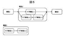
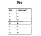
- 6 is a table showing the relationship between software components (installed functions) and corresponding tasks. It is the figure which expressed the loading function which is allotted to arithmetic and control unit 1 with the model base design method. It is a table showing the task corresponding to the mounted function assigned to the arithmetic and control unit 1 at the time of model-based design.
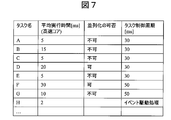
- 9 is a table illustrating an example of various parameters given to each of the tasks in the first embodiment.
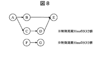
- 6 is an example of a task graph showing a data dependency relationship in the first embodiment.
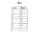
- 7 is a table showing an example of priority parameters given to each task in the first embodiment.
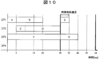
- 6 is an example of a time chart in the case where subtasks are not parallelized within task D in the first embodiment.
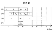
- 9 is a table showing a relationship between a task graph and a set average execution time when a submask that can be parallelized is parallelized in task D. 7 is an example of a time chart when the subtasks in the task D are parallelized in the first embodiment.
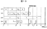
- FIG. 9 is an example of a time chart in the case where a time constraint violation occurs due to the occurrence of the event driven processing task H in the first embodiment.
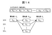
- FIG. 16 is a diagram showing a method of parallelizing task D and a priority setting method in the first modification of the first embodiment.
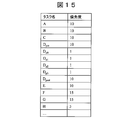
- 11 is a list showing a setting example of task priority parameters in Modification 1 of the first embodiment.
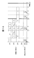
- 9 is an example of a time chart showing an operation in Modification 2 of the first embodiment.
- FIG. 11 is a schematic block diagram showing a configuration part related to arithmetic processing in the arithmetic control device of the multi-core processor according to the second embodiment.
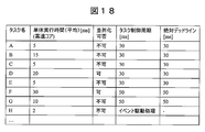
- 11 is a table for explaining an example of various parameters given to each of the tasks in the second embodiment.
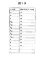
- 9 is a list showing an example of setting deadline parameters in the second embodiment.
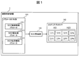
- FIG. 1 is a schematic block diagram showing the components related to the arithmetic processing in the arithmetic control device of the multi-core processor according to the first embodiment.
- the arithmetic and control unit 1 includes a parameter assigning unit 101, a multicore processor 102, and a task assigning unit 103.
- the parameter assigning unit 101 has a function of assigning information about hardware and software necessary for controlling the vehicle to the task as parameters and storing the information in the storage unit.
- the parameters related to hardware include the multi-core configuration of the multi-core processor 102, bus wiring information, sensing information (sensor value) of a sensor (not shown), and the like.
- the parameters stored in the parameter assigning unit 101 can also serve as a judgment index when the task allocating unit 103 performs allocation.
- the parameter assignment unit 101 includes a task control cycle parameter storage unit 1011, a task priority parameter storage unit 1012, and a task dependency relationship parameter 1013.
- the task control cycle parameter storage unit 1011 stores parameters that define the control cycle of each task executed by the multicore processor 102.
- the task priority parameter storage unit 1012 stores a parameter that defines a priority indicating the degree to which each task is preferentially processed (executed) in relation to other tasks.
- the task dependency relationship parameter storage unit 1013 stores a dependency relationship parameter indicating a dependency relationship between tasks.
- the dependency relationship parameter indicates a relationship in which the end of task A is the start condition of task B, for example, because the result of processing by certain task A is processed as the input of the next task B.
- the multi-core processor 102 has a plurality of cores 1 to 8, and each core 1 to 8 is configured to be able to execute task processing in parallel.
- the multi-core processor 102 can include two cores each having two different performances, four cores each.
- cores 1 to 4 having relatively high performance are referred to as high-speed operating cores 1021
- cores 5 to 8 having low performance are referred to as low-speed operating cores 1022.
- the number of performance stages is not limited to two, and may be three or more, or all cores may have the same performance.
- the task allocation unit 103 allocates each task to each core of the multi-core processor 102 based on the parameters (task control period, task priority, task dependency relationship, etc.) acquired from the parameter assignment unit 101.
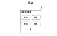
- the on-board functions required for such an arithmetic and control unit 1 are given in several formats. For example, as shown in FIG. 2, consider a case where various functions 1, 2, 3, 4,... Are described as software components in source code such as C language and given to the arithmetic and control unit 1.
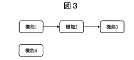
- the dependency relationships among the functions 1, 2, 3, 4,... are decoded. For example, it is determined based on the source code that the function 2 can be executed after the execution of the function 1 is completed and the function 3 can be executed after the execution of the function 2 is completed.
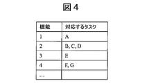
- FIG. 4 shows an example of the relationship between each function 1, 2, 3, 4 (software component) and the task.
- the task is defined in a form corresponding to each function as shown in Fig. 6.
- the corresponding tasks are defined for the sub-functions 2-1, 2-2, 2-3, 4-1, 4-2 in the functions 2 and 4, respectively.
- various parameters are generated for each task based on the source code of the software component, for example, as shown in the table of FIG. 7.
- parameters such as average execution time (when a high-speed core is used), parallelization of subtasks included in each task, and task control cycle are generated.
- the task control cycle parameter is stored in the task control cycle parameter storage unit 1011. Note that FIG. 7 shows the case where the average execution time is calculated and the parameters are determined for the task H corresponding to the event driven processing (interrupt processing), which is different from the functions 1 to 4.
- FIG. 8 shows an example of a task graph when executing the tasks shown in FIG.
- the task graph is generated by the arithmetic and control unit 1 according to the task control cycle, the task dependency, and other parameters.
- Each task is classified for each task having the same task control cycle, and is ordered according to the task dependency relationship.
- one task graph is formed for tasks A to E operating in the control period of 30 ms, and another task graph is formed for tasks F and G operating in the control period of 50 ms.
- the inter-task dependency relationships are represented by the arrows between the tasks. This dependency relationship is described in the task dependency relationship parameter 1013.
- a set of multiple tasks arranged in series is executed in one core in the multiprocessor 102, and different sets of tasks can be executed in different cores. For example, tasks A, B, and E can be executed in core 1, tasks C and D can be executed in core 2, and tasks F and G can be executed in core 3.
- FIG. 9 shows an example of priorities defined for each task.
- the numbers in FIG. 9 mean that the smaller the number, the higher the priority. For example, tasks F and G have priority “15”, and tasks A to E have higher priority “10”.
- the task H has a higher priority “5” than this.
- a priority and a task control cycle are given to each task by a control policy that a task having a shorter task control cycle is given a higher priority.
- FIG. 10 shows an example of a time chart when each task is executed (calculation is executed) according to the task control cycle, the dependency, and the priority determined as described above. In this FIG. 10, it is assumed that task switching on the core and time overhead associated with task division do not occur.
- Tasks A to E having a task control period of 30 ms are executed based on the dependency relationship according to the task dependency parameter.
- the tasks A and B and the tasks C and D can be executed in parallel (simultaneously) by the different cores 1 and 2.
- A, C, D, and E must be executed in that order, so that the processing becomes a neck (critical path), and depending on the execution time of each task, the periodic constraint of 30 [ms] is satisfied. It is not possible to do so, and time constraint violation will occur.
- a task that is further divided into a plurality of subtasks, and the subtasks can be parallelized are The execution time is shortened by executing parallelization.
- the division into subtasks can be determined and executed by the task allocation unit 103 based on the task control period parameter, the task priority parameter, the task dependency relationship, and the like.
- FIG. 11 shows a task graph when the task D is divided into a plurality of subtasks D pre , D p0 to D p3 , and D post , and some of the subtasks (for example, subtasks D p0 to D p3 ) are parallelized.
- An example of the determined average execution time (when using a high-speed core) is shown.
- At least two or more of the plurality of subtasks generated from one task D are parallelized and can be simultaneously executed in different cores, so that the total execution time (average) of the tasks can be shortened. ..
- the plurality of subtasks are pre- parallelized subtask D pre (21), parallelization target subtask D p (22) (D p0 to D p3 ), and parallel. It can be divided into post- task subtasks D post (23).
- the pre-parallelization subtask D pre1 is the first subtask to be executed among the subtasks in the task D.
- a plurality of parallelization target subtasks D p can be executed in parallel in a plurality of cores.
- the post- parallelization subtask D post is a task executed when the execution of all the parallelization target subtasks D p1 to D p3 is completed. In this way, by placing subtasks that are not the target of parallelization before and after the parallelization target subtask D p , it is possible to easily predict the execution time and reduce the processing load on the arithmetic and control unit 1. ..
- the total Ttotal of the average execution time of each subtask is equal to or less than the average execution time Td of the original task D.
- the newly created subtasks D pre , D p0 to D p3 , and the dependency relationship among D post , and the average execution time are stored in the parameter assigning unit 101.
- FIG. 12 shows an example of a time chart when the task D is divided into a plurality of subtasks and parallelized as shown in FIG.
- the subtasks D p0 to D p3 that can be parallelized are preferentially processed, and before that, the pre-parallelization subtask D pre processes after the execution of the task C. Be started.
- the pre-parallelization subtask D pre processes after the execution of the task C. Be started.
- the pre-parallelization subtask D pre processes after the execution of the task C. Be started.
- the pre-parallelization subtask D pre processes after the execution of the task C. Be started.
- the pre-parallelization subtask D pre processes after the execution of the task C. Be started.
- the subtasks D p0 to D p3 can be assigned to the four cores 1 to 4 to start processing at the same time.
- the parallelized subtask D post can be started thereafter. Further, the core 1 can resume the execution of the suspended task B.
- task F which has a task control cycle of 50 ms and is being executed in core 3, suspends the processing once parallel processing can be started. Then, the core 3 starts executing the subtask D p2 which is the target of the parallelization process. After the end of sub D p3 , the processing of task F, which has been suspended, is restarted in core 3.
- task F can be decomposed into subtasks for parallel processing (see FIG. 7), it can be the target of parallel processing.
- the task F has a long task control cycle, and therefore has a lower priority than the tasks A to E. Therefore, the processing can be ended within a predetermined task control cycle without executing the parallelization processing. Therefore, in the example of FIG. 12, the task F does not execute the subtask parallelization process. In this way, even for tasks that can be parallelized, it is possible to choose not to execute parallelization if it is possible to complete the processing within a predetermined task control cycle.
- the priority of the subtasks Fp can be set lower than the priority of the task F before the division.
- ⁇ Modification 1> 13 to 15 show a modified example 1 of the first embodiment.
- This modification 1 assumes a case where an interrupt task H occurs during processing in the cores 1 to 4 of the parallelization target subtasks D p0 to D p3 , and FIG. 13 shows an example of the time chart. ..
- the task H When the task H occurs, the task H is executed by interrupting the execution of the subtask D p3 in the core 4, for example.
- the task H which is an event-driven processing task, is randomly generated in response to the occurrence of an event regardless of the task control cycle, unlike the tasks A to G having a task control cycle. Therefore, it is difficult for the designer to design the execution timing of the task H in advance. Note that the priority of the task H can be generally set higher than that of other tasks in order to enable execution of the task H on an occurrence basis.
- the post- parallelization subtask D post can be executed after the completion of the parallelization target subtask D p . Therefore, if the execution start time of the task D post is delayed due to the operation of the task H, as a result, the processing for the tasks A to E may not be completed during the task control cycle, and a time constraint violation may occur (FIG. 13). reference).
- the priority of the parallelization target subtask D p is set. Is changed to a higher priority P high as compared with the pre-parallelization processing subtask and the post-parallelization processing tab task.
- This priority P high is set higher than the priority of the event driven processing task H.
- the priorities before the parallelization are inherited and the priorities are adjusted in relation to other tasks A to C, E to H, and the like. You can For example, if there is another task that has a higher priority than the original task D, the priority can be adjusted so that that task is given priority and executed.
- the parallelization target subtasks D p0 to D p3 the execution fluctuation when the operation inhibition by another task occurs directly leads to the violation of the execution time constraint. Therefore, only the parallelization target subtasks D p0 to D p3 are given the highest possible priority. This makes it possible to guarantee the operation of a series of tasks including the parallelization target subtask.
- FIG. 16 shows a modification 2 of the first embodiment.
- This modified example 2 shows an example in which the interrupt task H occurs during the processing in the cores 1 to 4 of the tasks A to G as in the modified example 1.
- the task allocation unit 103 is configured to use the core 5 only for processing the interrupt task H when the interrupt task H occurs.
- a dedicated core for task H When applying the first embodiment, if it is not possible to block the operation of task H, which is an event-driven process, it is possible to define a dedicated core for task H separately.
- a multi-core processor 102 having two kinds of core groups (cores 1 to 4) for processing tasks A to G having a task control cycle and a core group (core 5) dedicated to event driven processing is used. be able to.
- the multi-core processor 102 has such a configuration, the overall processor usage efficiency may be reduced by separately providing the event-driven processing dedicated core (core 5).
- the parallelization target subtask is described as one case, and in this case, the parallelization target subtask can be given the highest priority.
- the parallelization target subtask can be given the highest priority.
- the above embodiment has been described on the premise that the multi-core processor 102 has one core type.
- the method of this embodiment can be applied to a heterogeneous multi-core or many-core processor having a plurality of types of cores in one chip.
- the tasks A to G having the task control cycle have a high processing load with respect to the task H which is the event driven processing, and the case where the frequency of appearance of the task H which is the event driven processing is low, such a heterogeneous core is used.
- a heterogeneous core is used.
- FIG. 17 is a schematic block diagram showing the components related to the arithmetic processing in the arithmetic control device of the multi-core processor according to the second embodiment.
- the same parts as those in the first embodiment (FIG. 1) are designated by the same reference numerals in FIG. 17 as in FIG.
- the parameter assignment unit 101 does not have the task priority parameter storage unit 1012, and instead, a dead deadline indicating an absolute deadline, which is the time when each task should absolutely complete processing.
- a deadline parameter storage unit 1014 that stores line parameters is provided. That is, in the second embodiment, when a certain task is decomposed into subtasks and parallel processing is executed, the absolute deadline is changed instead of increasing the priority of the subtask, and the parameter is set as a parameter. It is supposed to be remembered. By changing the absolute deadline of a subtask to be parallelized, a task with a close absolute deadline is preferentially executed, and as a result, it becomes possible to comply with the time constraint of task execution.
- the absolute deadline which is the absolute deadline
- the absolute deadline is generated and stored as a parameter, but instead of the absolute deadline, for example, a relative time from the start time of the task control cycle is generated and stored as a deadline. It is also possible.
- FIG. 18 is a table showing various parameters for each task generated based on the source code of the software component in the second embodiment.
- the absolute deadline can be made shorter than the absolute deadline of the original task D.
- the absolute deadline is set back to 20 ms by calculating backward from the calculation limit time, and is set shorter than the original absolute deadline (30 ms).
- the execution of the interrupt task H makes it difficult to guarantee the deadline of the parallelization target subtasks D p0 to D p3 .
- cores for processing tasks having a task control cycle and cores (cores dedicated to processing event-driven processing tasks (cores) are used. It is also possible to adopt a multi-core processor having two types of 5). When such a configuration is adopted, there is a demerit that the overall processor usage efficiency decreases by providing a dedicated event-driven processing core, but the predictability of task behavior on a multi-core processor is improved and the cycle constraint is satisfied. It becomes possible to guarantee.
- Information such as a program, a table, and a file that realizes each function can be stored in a memory, a hard disk, a recording device such as an SSD (Solid State Drive), or a recording medium such as an IC card, an SD card, or a DVD.
- SSD Solid State Drive
- a recording medium such as an IC card, an SD card, or a DVD.
- a combination of a task group with a control period of 30 ms, a task group with a control period of 50 ms, and an event driven task is shown, but the present invention is not limited to this.
- the present invention reduces the fluctuation of the processing time by changing the processing priority of the task generated by parallelization regardless of the existence of a plurality of types of control cycles, different deadline times, the presence or absence of event-driven processing, etc. It is possible to increase the guarantee possibility of the execution time constraint.
- SYMBOLS 1 Arithmetic control device, 101... Parameter providing part, 1011... Task control period parameter storage part, 1012... Task priority parameter storage part, 1013... Task dependency parameter storage part, 1014... Deadline parameter storage part, 102... Multi-core Processors 1021, 1022... Core, 103... Task assigning unit.
Landscapes
- Engineering & Computer Science (AREA)
- Software Systems (AREA)
- Theoretical Computer Science (AREA)
- Physics & Mathematics (AREA)
- General Engineering & Computer Science (AREA)
- General Physics & Mathematics (AREA)
- Devices For Executing Special Programs (AREA)
Abstract
複数のコアを有するプロセッサを用いたシステムにおいて、複数のコア上で同時に異なる処理を行った際の処理時間の変動を低減することを可能にし、これによりシステムの挙動予測性を高め、実行時間制約の保証可能性を高める。本発明に係る演算制御装置は、複数のコアを有するプロセッサと、前記複数のコアに対し、タスクを割り当てるタスク割当部とを備える演算制御装置である。前記タスク割当部は、前記タスクを構成する複数のサブタスクを並列化処理の対象とすることが可能であるか否かを判断し、並列化処理が可能である場合には、所定の条件下で前記複数のサブタスクを前記複数のコアに割り当てるよう構成される。
Description
本発明は、演算制御装置に関し、より詳しくはマルチコア又はメニーコアと言われる複数コアを有するプロセッサを制御する演算制御装置に関する。
近年、組込み用プロセッサにおける性能向上が進み、高負荷な演算処理の導入が自動車(特に自動運転)、ビッグデータ処理、創薬、遺伝子解析、産業機器等の分野において進んでいる。その結果、それらの分野における制御装置において求められる処理性能が増大している。このため、マルチコアもしくはメニーコアプロセッサなど複数コアを有するプロセッサを活用した制御装置(ECU: Electronic Control Unit)が採用され、その処理性能向上が求められている。
例えば自動車分野においては、高度な自動運転システムの実現に向け、自動運転を制御する上位の制御装置である自動運転ECUを筆頭に、制御装置の処理負荷の増大が課題となっている。このため、自動車分野においても、2コア、4コア、8コアといったマルチコアプロセッサの導入が開始されている。今後も更にコア数は増大し、コア数が例えば10以上のメニーコアプロセッサの利用開始も想定される。
一方で、同分野におけるソフトウェア設計においては、例えばモデルベースデザインからの自動ソースコード生成など、シングルコアプロセッサ向けの設計手法が依然用いられる場合がある。シングルコアプロセッサ向けの既存の設計手法のまま単純にマルチコアプロセッサやメニーコアプロセッサに移行するだけでは、今後の負荷増大トレンドにおける、これらプロセッサの性能メリットを活かすことが難しくなる。特許文献1ではこのような背景に対し、マルチコアプロセッサに対して複数のタスクを効率的に割り当てる(準最適なスケジューリングを提供する)例が開示されている。
一方で、特許文献1では、通常時は事前に規定されるスケジューリング方式に基づき各プロセッサコアへの処理を割り当てた静的なスケジューリングを用いるが、負荷が高い状況において、タスクを効率的に実行するための動的スケジューリングを行う例が示されている。自動車分野や産業機器分野においては、制御の安定性のため実行時間制約を保証することが強く求められるが、同文献については実行時間制約への言及はなく、仮に通常動作時(静的スケジューリングで動作する場合)には設計者により適切なスケジューリングが行われていたとしても、少なくとも動的にスケジューリングを行った際の実行時間制約の保証は困難である。特にマルチコアプロセッサにおいては、ある処理が別の処理の実行時間へ影響を与える場合がある。この場合、実行時間の制約を保証することが困難になり得る。このため、実行時間制約を満たすためには、複数のコア上で同時に演算を行った際の処理時間の変動に対応するための方法が必要となる。
本発明の目的は、上述のような複数のコアを有するプロセッサを用いたシステムにおいて、複数のコア上で同時に異なる処理を行った際の処理時間の変動を低減することを可能にし、これによりシステムの挙動予測性を高め、実行時間制約の保証可能性を高めることを可能にした演算制御装置を提供することである。
本発明に係る演算制御装置は、複数のコアを有するプロセッサと、前記複数のコアに対し、タスクを割り当てるタスク割当部とを備える演算制御装置である。前記タスク割当部は、前記タスクを構成する複数のサブタスクを並列化処理の対象とすることが可能であるか否かを判断し、並列化処理が可能である場合には、所定の条件下で前記複数のサブタスクを前記複数のコアに割り当てるよう構成される。
本発明によれば、マルチコアプロセッサを用いる演算制御装置において、複数のコア上で同時に異なる処理を行った際の処理時間の変動を低減することを可能にし、これによりシステムの挙動予測性を高め、実行時間制約の保証可能性を高めることができる。
以下、添付図面を参照して本実施形態について説明する。添付図面では、機能的に同じ要素は同じ番号又は対応する番号で表示される場合もある。なお、添付図面は本開示の原理に則った実施形態と実装例を示しているが、これらは本開示の理解のためのものであり、決して本開示を限定的に解釈するために用いられるものではない。本明細書の記述は典型的な例示に過ぎず、本開示の特許請求の範囲又は適用例を如何なる意味においても限定するものではない。
本実施形態では、当業者が本開示を実施するのに十分詳細にその説明がなされているが、他の実装・形態も可能で、本開示の技術的思想の範囲と精神を逸脱することなく構成・構造の変更や多様な要素の置き換えが可能であることを理解する必要がある。従って、以降の記述をこれに限定して解釈してはならない。
[第1の実施の形態]
図1を参照して、第1の実施の形態に係る演算制御装置を説明する。以下では、コアの数が8個であるマルチコアプロセッサを制御する演算制御装置を例として説明するが、コアの個数は特定のものに限定されるものではない。例えば、コアが10個以上のメニーコアプロセッサを制御する演算制御装置にも、本開示の技術的思想の範囲と精神を逸脱することなく、同様の方式の採用が可能である。
図1を参照して、第1の実施の形態に係る演算制御装置を説明する。以下では、コアの数が8個であるマルチコアプロセッサを制御する演算制御装置を例として説明するが、コアの個数は特定のものに限定されるものではない。例えば、コアが10個以上のメニーコアプロセッサを制御する演算制御装置にも、本開示の技術的思想の範囲と精神を逸脱することなく、同様の方式の採用が可能である。
図1は、第1の実施の形態に係るマルチコアプロセッサの演算制御装置のうち、演算処理に関連する構成部分を示した概略ブロック図である。演算制御装置1は、パラメータ付与部101と、マルチコアプロセッサ102と、タスク割当部103とを備える。
パラメータ付与部101は、車両を制御するために必要となるハードウェア及びソフトウェアに関する情報をパラメータとしてタスクに付与し、記憶部に記憶する機能を有する。ハードウェアに関するパラメータには、マルチコアプロセッサ102のマルチコア構成、バス配線情報、センサ(図示せず)のセンシング情報(センサ値)等が含まれる。
パラメータ付与部101に記憶されるパラメータは、タスク割当部103による割当を行う場合の判断指標ともなり得る。一例として、パラメータ付与部101は、タスク制御周期パラメータ記憶部1011と、タスク優先度パラメータ記憶部1012と、タスク依存関係パラメータ1013とを備える。タスク制御周期パラメータ記憶部1011は、マルチコアプロセッサ102により実行される各タスクの制御周期を規定するパラメータを記憶する。また、タスク優先度パラメータ記憶部1012は、各タスクが他のタスクとの関係で優先して処理(実行)されるべき度合を示す優先度を規定するパラメータを記憶する。
タスク依存関係パラメータ記憶部1013は、タスク間の依存関係を示す依存関係パラメータを記憶する。依存関係パラメータは、例えばあるタスクAで処理した結果を次のタスクBの入力として処理するため、タスクAの終了がタスクBの開始条件となるような関係を示す。
マルチコアプロセッサ102は、複数のコア1~8を有しており、各コア1~8はそれぞれ並列にタスク処理を実行可能に構成されている。一例として、マルチコアプロセッサ102は、性能の異なる2種類のコアを4コアずつ有することができる。ここでは、相対的に性能の高いコア1~4を高速動作コア1021、性能の低いコア5~8を低速動作コア1022と呼称する。性能の段階は2段階には限られず、3段階以上であってもよいし、全てのコアが同一の性能を有していてもよい。
タスク割当部103は、パラメータ付与部101から取得されたパラメータ(タスク制御周期、タスク優先度、タスク依存関係など)に基づき、各タスクをマルチコアプロセッサ102の各コアへ割り当てる。
このような演算制御装置1に対して要求される搭載機能は、いくつかの形式により与えられる。例えば、図2に示すように、各種機能1、2、3、4・・・が、ソフトウェアコンポーネントとしてC言語などのソースコードにて記載されて演算制御装置1に与えられる場合を考える。
この場合、同ソースコードに基づき、図3に示すように、各機能1、2、3、4・・・(ソフトウェアコンポーネント間)の依存関係が解読される。例えば、機能2は、機能1の実行が完了した後において実行が可能であり、機能3は機能2の実行が完了した後において実行が可能であることがソースコードに基づき解読される。
さらに、各機能1、2、3、4・・・をマルチコアプロセッサ102に割り当てるためのタスクが定義される。各機能1、2、3、4(ソフトウェアコンポーネント)とタスクとの関係の一例を図4に示す。
また異なる入力情報の例として、図5のようなモデルベース設計手法にて記述されたモデルが与えられた場合には、図6のように各機能と対応させる形でタスクが定義される。例えば、機能2、4中のサブ機能2-1、2-2、2-3、4-1、4-2に対しても、それぞれ対応するタスクが定義される。
タスクが定義されると、図7のテーブルに示すように、タスクの各々について、各種のパラメータが、例えばソフトウェアコンポーネントのソースコードに基づいて生成される。一例としては、図7に示すように、平均実行時間(高速コアを用いた場合)、各タスクに含まれるサブタスクの並列化の可否、及びタスク制御周期等のパラメータが生成される。このうちタスク制御周期のパラメータは、タスク制御周期パラメータ記憶部1011に記憶される。
なお、図7は、機能1~4とは別の、イベント駆動処理(割り込み処理)に対応するタスクHについても平均実行時間を計算し、パラメータを決定した場合について示している。
なお、図7は、機能1~4とは別の、イベント駆動処理(割り込み処理)に対応するタスクHについても平均実行時間を計算し、パラメータを決定した場合について示している。
図8に、図7に示したタスクを実行する場合のタスクグラフの一例を示す。タスクグラフは、演算制御装置1により、タスク制御周期、タスク依存関係、その他のパラメータに従って生成される。各タスクは、同一のタスク制御周期を有するタスク毎に分類されるとともに、タスク依存関係に従って順序付けされる。この例では、30msの制御周期で動作するタスクA~Eについての1のタスクグラフが形成され、50msの制御周期で動作するタスクF、Gについて別のタスクグラフが形成されている。
図8に例示されるタスクグラフでは、各タスク間の矢印によりタスク間の依存関係が表現されている。この依存関係は、タスク依存関係パラメータ1013に記述される。このようなタスクグラフが形成されると、直列に並ぶ複数のタスクの組は、マルチプロセッサ102中の1つのコアにおいて実行され、異なる組のタスクは、異なるコアにおいて実行され得る。例えば、タスクA、B、Eは、コア1において実行され、タスクC、Dはコア2において実行され、タスクF、Gはコア3にて実行され得る。
また、タスクが定義されると、タスク毎に優先度がパラメータとして定義され、タスク優先度パラメータ記憶部1012に記憶される。図9は、各タスクについて定義された優先度の一例を示している。この図9の数字は、小さい数字であるほど優先度が高いことを意味している。例えば、タスクF、Gは優先度「15」であり、タスクA~Eの方がより高い優先度「10」を有する。タスクHは、これよりも更に高い優先度「5」を有する。この例では、タスク制御周期が短いタスクほど、高い優先度を与える、という制御ポリシーにより、優先度及びタスク制御周期が各タスクに与えられている。
上述のようにして決定されたタスク制御周期、依存関係、優先度に従って各タスクを実行した(演算を実行した)場合におけるタイムチャートの一例を図10に示す。この図10では、コア上でのタスク切り替えや、タスク分割に伴う時間オーバヘッドは発生しないものと仮定している。
タスク依存関係パラメータに従った依存関係に基づき、30msのタスク制御周期を有するタスクA~Eが実行される。このとき、タスクA、BとタスクC、Dとは、異なるコア1、2により並列に(同時に)実行され得る。しかし、A、C、D、Eはその順に実行されなければならず、このため、その処理がネック(クリティカルパス)となり、個々のタスクの実行時間次第では、30[ms]の周期制約を満たすことは出来ず、時間制約違反が生じてしまう。
そこで、本実施の形態では、クリティカルパス上にある複数のタスクA、C、D、Eのうち、更に複数のサブタスクに分割され、しかもそのサブタスクが並列化可能なタスクに関し、所定の条件下で並列化を実行することで、実行時間を短縮する。サブタスクへの分割は、タスク割当部103において、タスク制御周期パラメータ、タスク優先度パラメータ、タスク依存関係等に基づいて判断され、実行され得る。
図11に、タスクDを複数のサブタスクDpre、Dp0~Dp3、及びDpostに分割し、その一部のサブタスク(例えばサブタスクDp0~Dp3)を並列化した場合におけるタスクグラフと、決定される平均実行時間(高速コアの使用時)の例を示す。
1つのタスクDから生成された複数のサブタスクは、その中の少なくとも2以上が並列化され、異なるコアにおいて同時に実行可能とされることにより、タスクの総実行時間(平均)を短縮することができる。
好適には、タスクD中の複数のサブタスクを並列化するにあたり、複数のサブタスクを並列化前サブタスクDpre(21)、並列化対象サブタスクDp(22)(Dp0~Dp3)、及び並列化後サブタスクDpost(23)に分割することができる。並列化前サブタスクDpre1は、タスクD中のサブタスク中で最初に実行されるサブタスクである。この並列化前サブタスクDpre1の実行後、複数の並列化対象サブタスクDpが並列に、複数のコアにおいて実行され得る。また、並列化後サブタスクDpostは、並列化対象サブタスクDp1~Dp3の実行が全て終了した場合に実行されるタスクである。
このように、並列化対象サブタスクDpの前後に、並列化の対象外のサブタスクを置くことで、実行時間の予測が容易になるとともに、演算制御装置1での処理負荷も軽減することができる。
このように、並列化対象サブタスクDpの前後に、並列化の対象外のサブタスクを置くことで、実行時間の予測が容易になるとともに、演算制御装置1での処理負荷も軽減することができる。
図11のように、1つのタスクDが複数のサブタスクに分割される場合、サブタスクの各々の平均実行時間(高速コアの使用時)の合計Ttotalは、元のタスクDの平均実行時間Td以下となるように設定する。前述のように、コア上でのタスク切替や、タスク分割に伴う時間オーバヘッドは仮定しないならば、平均実行時間の合計Ttotalは、元のタスクDの平均実行時間Tdと等しい値とすることができる(5×6=30ms)。なお、この新たに生成されたサブタスクDpre、Dp0~Dp3、Dpostの間の依存関係、及び平均実行時間は、パラメータ付与部101に記憶される。
図11のようにしてタスクDが複数のサブタスクに分割され且つ並列化処理された場合におけるタイムチャートの一例を、図12に示す。この例では、30msの制御周期を満足するため、並列化処理が可能なサブタスクDp0~Dp3が優先的に処理され、その前に並列化前サブタスクDpreがタスクCの実行終了後に処理を開始される。並列化処理の開始の際、コア1上でタスクBが実行中であれば、それを一度中断することもできる。これにより、4つのコア1~4の全てを実行可能状態とすることができ、それぞれにサブタスクDp0~Dp3を割り当て、4つのコア1~4において同時に処理を開始することができる。サブタスクDp0~Dp3に関しては、並列化前サブタスクDpreの終了後、同期信号を発生させることにより、処理の開始タイミングが揃うようにすることが好適である。サブタスクDp0~タスクDp3の実行が全て終了すると、その後に並列化後サブタスクDpostの実行を開始することができる。また、コア1では、中断していたタスクBの実行を再開することができる。
また、50msのタスク制御周期を有しコア3で実行中であるタスクFも、タスクBと同様に、並列化処理が開始可能となった段階で、一度処理を中断する。その後、並列化処理の対象とされたサブタスクDp2の実行をコア3において開始する。サブDp3の終了後、コア3では再び中断されていたタスクFの処理が再開される。
なお、タスクFもタスクDと同様に、サブタスクに分解して並列化処理が可能であれば(図7参照)並列化処理の対象としてもよいことは言うまでもない。ただし、タスクFは、タスクDとは異なり、タスク制御周期が長く、このため、優先度がタスクA~Eに比べ低い。このため、並列化処理を実行しなくても、所定のタスク制御周期の中で処理を終了することができる。このため、図12の例では、タスクFに関してはサブタスクの並列化処理は実行していない。このように、並列化処理が可能なタスクにおいても、定められたタスク制御周期の中で処理を完了することが可能であれば並列化処理を実行しないことを選択することが可能である。なお、タスクFをサブタスクFpに分解して並列化処理を実行する場合においては、サブタスクFpの優先度は、分割前のタスクFの優先度に比べ低く設定することができる。
<変形例1>
図13~図15は、第1の実施の形態の変形例1を示している。この変形例1は、並列化対象サブタスクDp0~Dp3のコア1~4での処理中に割込みタスクHが発生した場合を想定しており、図13はそのタイムチャートの一例を示している。
図13~図15は、第1の実施の形態の変形例1を示している。この変形例1は、並列化対象サブタスクDp0~Dp3のコア1~4での処理中に割込みタスクHが発生した場合を想定しており、図13はそのタイムチャートの一例を示している。
タスクHが発生した場合、タスクHは、例えばコア4において、サブタスクDp3の実行を中断して実行される。イベント駆動処理タスクであるタスクHは、タスク制御周期を有するタスクA~Gとは異なり、タスク制御周期とは無関係にイベントの発生に対応してランダムに生成される。このため、タスクHは、設計者が事前に実施タイミングを設計することは難しい。なお、発生ベースでのタスクHの実行を可能にするため、タスクHの優先度は、一般に他のタスクに比べ高く設定され得る。
しかし、並列化後サブタスクDpostは、並列化対象サブタスクDpの完了後に実行可能となる。このため、タスクHの動作によりタスクDpostの実行開始時刻が遅れると、結果、タスクA~Eについての処理がタスク制御周期中に完了せず、時間制約違反が発生する虞がある(図13参照)。
このように、イベント駆動処理(割込み処理)など、優先度が並列化対象サブタスクに対して高く設定されるタスクが存在する場合、並列化対象サブタスクの一部の処理が中断され、実行時間制約を満たすことができない場合があり得る。
そこで、この第1の実施の形態の変形例1では、図14及び図15に示すように、全てのサブタスクに対し同一の優先度Pdを与える代わりに、並列化対象サブタスクDpの優先度を、並列化処理前サブタスク、及び並列化処理後タブタスクに比較して高い優先度Phighに変更する。この優先度Phighは、イベント駆動処理タスクHの優先度よりも高くされる。例えば、並列化前サブタスクDpre及び並列化後サブタスクDpostに対しては、その前後のタスクC、Eの優先度と同一の優先度(例:Pd=15)を付与する一方、並列化対象サブタスクDp0~Dp3に対しては、タスクC,E、更にはタスクHよりも高い優先度(例:Phigh=1)を付与する。
このように、並列化前サブタスクDpre及び並列化後サブタスクDpostに関しては、並列化前の優先度を引き継ぎ、他タスクA~C、E~H等との関係で優先度の調整を行ことができる。例えば、元のタスクDよりも高い優先度を有する他のタスクがあれば、そちらを優先して実行するよう、優先度を調整することはできる。ただし、並列化対象サブタスクDp0~Dp3については、他のタスクによる動作阻害が発生した際の実行ゆらぎが、直接的に実行時間制約の違反に繋がってしまう。そのため、並列化対象サブタスクDp0~Dp3のみについては可能な限り最大の優先度を与える。これにより、並列化対象サブタスクを含む一連のタスクについて、動作保証を行うことができる。
<変形例2>
図16は、第1の実施の形態の変形例2を示している。この変形例2は、変形例1と同様に、タスクA~Gのコア1~4での処理中に割込みタスクHが発生した例を示す。ただし、この変形例2は、割り込みタスクHが発生した場合において、コア5を割り込みタスクHの処理専用として利用するよう、タスク割当部103が構成されている。
図16は、第1の実施の形態の変形例2を示している。この変形例2は、変形例1と同様に、タスクA~Gのコア1~4での処理中に割込みタスクHが発生した例を示す。ただし、この変形例2は、割り込みタスクHが発生した場合において、コア5を割り込みタスクHの処理専用として利用するよう、タスク割当部103が構成されている。
第1の実施の形態を適用するにあたり、イベント駆動処理であるタスクHの動作を阻害することは不可能である場合は、タスクHについて別途専用にコアを定義することが可能である。この場合、タスク制御周期を有するタスクA~Gの処理のためのコア群(コア1~4)と、イベント駆動処理専用のコア群(コア5)の2種類が存在するマルチコアプロセッサ102を利用することができる。マルチコアプロセッサ102がこのような構成を取る場合、イベント駆動処理専用コア(コア5)を別途設けることにより、全体的なプロセッサ使用効率は低下することがあり得る。しかし、その一方で、マルチコアプロセッサ102上でのタスク挙動の予測性を高め、周期制約の充足を保証することが可能となる。
また、この変形例2では、タスク制御周期を有するタスクA~Gの動作が割り込みタスクHにより阻害されないことから、外部メモリやキャッシュ利用のタイミングが固定的となるため、キャッシュ利用効率向上による処理性能向上効果が期待できる。
なお、本実施の形態では簡単のため、並列化対象サブタスクが1つのケースで説明しており、その際には並列化対象サブタスクに最高の優先度を与えることが可能となる。しかし、実際には並列化すべきタスクが複数存在する場合が想定される。そのような場合においては、より時間制約の厳しい順に、最高優先度から優先度を順次下げて付与することが可能である。
また、上記の実施の形態では、コアの種類が1種類であるマルチコアプロセッサ102を前提として説明した。一つのチップ内に複数種類のコアを持つ、ヘテロジニアスなマルチコアもしくはメニーコアプロセッサにも、本実施の形態の方式は採用可能である。
タスク制御周期を有するタスクA~Gがイベント駆動処理であるタスクHに対して処理負荷が高いケースや、イベント駆動処理であるタスクHの出現頻度が低いケースなどでは、このようなヘテロジニアスなコアにおいて、より性能の高いコアへタスク制御周期を有するタスク割り当て、性能の低いコアへイベント駆動処理であるタスクHを割り当てることにより、更なる演算性能向上を図ることが可能となる。
タスク制御周期を有するタスクA~Gがイベント駆動処理であるタスクHに対して処理負荷が高いケースや、イベント駆動処理であるタスクHの出現頻度が低いケースなどでは、このようなヘテロジニアスなコアにおいて、より性能の高いコアへタスク制御周期を有するタスク割り当て、性能の低いコアへイベント駆動処理であるタスクHを割り当てることにより、更なる演算性能向上を図ることが可能となる。
[第2の実施の形態]
次に、第2の実施の形態に係る演算制御装置を、図17~図19を参照して説明する。
次に、第2の実施の形態に係る演算制御装置を、図17~図19を参照して説明する。
図17は、第2の実施の形態に係るマルチコアプロセッサの演算制御装置のうち、演算処理に関連する構成部分を示した概略ブロック図である。第1の実施の形態(図1)と同一の部分に関しては、図17において図1と同一の参照符号を付しているので、以下では重複する説明は省略する。
この第2の実施の形態では、パラメータ付与部101は、タスク優先度パラメータ記憶部1012は有しておらず、代わりに、各タスクが絶対に処理を完了すべき時刻である絶対デッドライン示すデッドラインパラメータを記憶するデッドラインパラメータ記憶部1014を備えている。すなわち、この第2の実施の形態では、あるタスクをサブタスクに分解して並列化処理を実行する場合において、そのサブタスクの優先度を高くするのではなく、その絶対デッドラインを変更し、パラメータとして記憶されるようにされている。並列化対象のサブタスクの絶対デッドラインが変更されることにより、絶対デッドラインが近いタスクが優先的に実行され、結果としてタスク実行の時間制約を遵守することが可能になる。なお、この例では、絶対期限である絶対デッドラインをパラメータとして生成・記憶しているが、絶対デッドラインに代えて、例えばタスク制御周期の開始時刻からの相対時刻をデッドラインとして生成・記憶することも可能である。
図18は、第2の実施の形態において、ソフトウェアコンポーネントのソースコードに基づいて生成された、タスクの各々についての各種パラメータを示すテーブルである。30msのタスク制御周期を有するタスクA~Eについて時間制約違反が生じてしまうと判断される場合には、並列化が可能であるタスクDについてサブタスク(Dpre、Dp0~Dp3、Dpost)への分割及び並列化が実行される。
図19に示すように、並列化対象サブタスクDp0~Dp3については、絶対デッドラインを元のタスクDの絶対デッドラインに比べ短くすることができる。ここでは、演算限界時間から逆算して絶対デッドラインを20msと定め、元の絶対デッドライン(30ms)よりも短くしている。デッドラインが長いままとされる場合、割込みタスクHが実行により、並列化対象サブタスクDp0~Dp3のデッドライン保証が困難となる。並列化対象サブタスクDp0~Dp3の絶対デッドラインをより短く設定することにより、タスクDp0~Dp3の実行優先度を高めることができる。
タスクHについては、第1の実施の形態の変形例2と同様に、タスク制御周期を有するタスクの処理用のコア(コア1~4)と、イベント駆動処理のタスクの処理専用のコア(コア5)の2種類が存在するマルチコアプロセッサを採用することも可能である。このような構成を取る場合、イベント駆動処理専用コアを別途設けることにより全体的なプロセッサ使用効率が低下するデメリットがあるが、マルチコアプロセッサ上でのタスク挙動の予測性を高め、周期制約の充足を保証することが可能となる。また周期処理タスクの動作が阻害されないことから、外部メモリやキャッシュ利用のタイミングが固定的となるため、キャッシュ利用効率向上による処理性能向上効果が期待できると同時に、動的なスケジューリングを行うことにより、第1の実施の形態における静的なスケジューリングよりもタスク設計工数の低減が可能となる。
以上、本発明の実施形態を説明したが、これらの実施形態は、例として提示したものであり、発明の範囲を限定することは意図していない。これら新規な実施形態は、その他の様々な形態で実施されることが可能であり、発明の要旨を逸脱しない範囲で、種々の省略、置き換え、変更を行うことができる。これら実施形態やその変形は、発明の範囲や要旨に含まれるとともに、特許請求の範囲に記載された発明とその均等の範囲に含まれる。
上記各構成、機能、処理部、処理手段等は、それらの一部を、例えば集積回路を設計する等によりハードウェアで実現してもよい。また、上記の各構成、機能等は、プロセッサがそれぞれの機能を実現するプログラムを解釈し、実行することによりソフトウェアで実現してもよい。各機能を実現するプログラム、テーブル、ファイル等の情報は、メモリ、ハードディスク、SSD(Solid State Drive)等の記録装置、ICカード、SDカード、DVD等の記録媒体に格納することができる。
上記各構成、機能、処理部、処理手段等は、それらの一部を、例えば集積回路を設計する等によりハードウェアで実現してもよい。また、上記の各構成、機能等は、プロセッサがそれぞれの機能を実現するプログラムを解釈し、実行することによりソフトウェアで実現してもよい。各機能を実現するプログラム、テーブル、ファイル等の情報は、メモリ、ハードディスク、SSD(Solid State Drive)等の記録装置、ICカード、SDカード、DVD等の記録媒体に格納することができる。
また例えば、上記実施形態において、制御周期30msのタスク群と50msのタスク群、及びイベント駆動タスクの組合せを示しているが、本発明はこれに限定されるものではない。複数種類の制御周期の存在、異なるデッドライン時刻、イベント駆動処理の有無等に依らず、本発明は並列化により生成されるタスクの処理優先権を変更することで、処理時間の変動を低減することができ、実行時間制約の保証可能性を高めることができる。
1…演算制御装置、101…パラメータ付与部、1011…タスク制御周期パラメータ記憶部、1012…タスク優先度パラメータ記憶部、1013…タスク依存関係パラメータ記憶部、1014…デッドラインパラメータ記憶部、102…マルチコアプロセッサ、1021、1022…コア、103…タスク割当部。
Claims (10)
- 複数のコアを有するプロセッサと、
前記複数のコアに対し、タスクを割り当てるタスク割当部と
を備える演算制御装置であって、
前記タスク割当部は、
前記タスクを構成する複数のサブタスクを並列化処理の対象とすることが可能であるか否かを判断し、並列化処理が可能である場合には、所定の条件下で前記複数のサブタスクを前記複数のコアに割り当てるよう構成される ことを特徴とする演算制御装置。 - 前記タスクにパラメータを付与するパラメータ付与部を更に備え、
前記パラメータ付与部は、タスクが他のタスクに比べ優先的に処理されるべき度合を示す優先度をパラメータとして付与し、
前記並列化処理の対象とされた前記サブタスクの優先度を、並列化前の元のタスクの優先度とは異なる優先度に変更する、請求項1に記載の演算制御装置。 - 前記パラメータ付与部は、前記タスクが処理される周期を示すタスク制御周期、及び前記複数のタスクの依存関係を示すタスク依存関係をパラメータとして付与し、
前記タスク割当部は、前記タスク制御周期及び前記タスク依存関係に基づいて、前記複数のコアに対し前記タスクを割り当てる、請求項2に記載の演算制御装置。 - 前記タスクは、前記タスク制御周期とは無関係に発生するイベント駆動処理タスクを含み、
前記パラメータ付与部は、前記並列化処理の対象とされた前記サブタスクに対し、前記イベント駆動処理タスクよりも高い優先度をパラメータとして付与する、請求項3に記載の演算制御装置。 - 前記タスクは、タスク制御周期とは無関係に発生するイベント駆動処理タスクを含み、
前記タスク割当部は、前記タスク制御周期を有するタスクを前記複数のコアのうちの第1のコアに割り当て、前記イベント駆動処理タスクを前記第1のコアとは異なる第2のコアに割り当てる、請求項1に記載の演算制御装置。 - 前記タスク割当部は、前記複数のサブタスクを、並列化前サブタスク、前記並列化前サブタスクの実行後に実行される並列化対象サブタスク、及び前記並列化対象サブタスクの実行後に実行される並列化後サブタスクに分割し、前記並列化対象サブタスクが前記並列化処理の対象とされるよう前記複数のコアにタスクを割り当てる、請求項1に記載の演算制御装置。
- 前記並列化対象サブタスクは、前記並列化前サブタスク及び前記並列化後サブタスクよりも高い優先度を設定される、請求項6に記載の演算制御装置。
- 前記並列化対象サブタスクは、分割前の元のタスクよりも高い優先度を設定される、請求項6又は7に記載の演算制御装置。
- 前記タスクにパラメータを付与するパラメータ付与部を更に備え、
前記パラメータ付与部は、タスクの処理が完了すべき時刻を示すデッドラインをパラメータとして付与し、
前記並列化処理の対象とされた前記サブタスクのデッドラインを変更する、請求項1に記載の演算制御装置。 - 前記プロセッサは、複数のコアの性能が互いに異なるヘテロジニアスプロセッサである、請求項1に記載の演算制御装置。
Priority Applications (1)
| Application Number | Priority Date | Filing Date | Title |
|---|---|---|---|
| DE112019005584.4T DE112019005584T5 (de) | 2018-12-12 | 2019-11-29 | Arithmetiksteuervorrichtung |
Applications Claiming Priority (2)
| Application Number | Priority Date | Filing Date | Title |
|---|---|---|---|
| JP2018232407A JP7385989B2 (ja) | 2018-12-12 | 2018-12-12 | 演算制御装置 |
| JP2018-232407 | 2018-12-12 |
Publications (1)
| Publication Number | Publication Date |
|---|---|
| WO2020121840A1 true WO2020121840A1 (ja) | 2020-06-18 |
Family
ID=71075338
Family Applications (1)
| Application Number | Title | Priority Date | Filing Date |
|---|---|---|---|
| PCT/JP2019/046724 Ceased WO2020121840A1 (ja) | 2018-12-12 | 2019-11-29 | 演算制御装置 |
Country Status (3)
| Country | Link |
|---|---|
| JP (1) | JP7385989B2 (ja) |
| DE (1) | DE112019005584T5 (ja) |
| WO (1) | WO2020121840A1 (ja) |
Cited By (3)
| Publication number | Priority date | Publication date | Assignee | Title |
|---|---|---|---|---|
| CN112114956A (zh) * | 2020-09-29 | 2020-12-22 | 中国银行股份有限公司 | 一种任务调度方法、装置和系统 |
| US20220004155A1 (en) * | 2018-11-15 | 2022-01-06 | Omron Corporation | Control system and control device |
| JP7188693B2 (ja) | 2018-09-12 | 2022-12-13 | 国立研究開発法人物質・材料研究機構 | グラフェンを用いた電極、その製造方法およびそれを用いた蓄電デバイス |
Families Citing this family (2)
| Publication number | Priority date | Publication date | Assignee | Title |
|---|---|---|---|---|
| JP7385536B2 (ja) * | 2020-06-30 | 2023-11-22 | 日立Astemo株式会社 | ソフトウェア開発支援装置及びソフトウェア開発支援方法 |
| KR102540724B1 (ko) * | 2020-12-14 | 2023-06-05 | 현대오토에버 주식회사 | 멀티 코어 시스템에서의 태스크 실행 관리 방법, 그리고 이를 구현하기 위한 장치 |
Citations (6)
| Publication number | Priority date | Publication date | Assignee | Title |
|---|---|---|---|---|
| JP2000099352A (ja) * | 1998-09-18 | 2000-04-07 | Fuji Xerox Co Ltd | ジョブ処理装置 |
| JP2009151645A (ja) * | 2007-12-21 | 2009-07-09 | Mitsubishi Electric Corp | 並列処理装置及びプログラム並列化装置 |
| WO2014068950A1 (ja) * | 2012-10-31 | 2014-05-08 | 日本電気株式会社 | データ処理システム、データ処理方法およびプログラム |
| JP2014160367A (ja) * | 2013-02-20 | 2014-09-04 | Mitsubishi Electric Corp | 演算処理装置 |
| JP2015225396A (ja) * | 2014-05-26 | 2015-12-14 | 日立オートモティブシステムズ株式会社 | 車両制御装置 |
| JP2016091137A (ja) * | 2014-10-31 | 2016-05-23 | コニカミノルタ株式会社 | 画像形成装置、特定処理実行方法、およびコンピュータプログラム |
Family Cites Families (2)
| Publication number | Priority date | Publication date | Assignee | Title |
|---|---|---|---|---|
| JPH01154237A (ja) * | 1987-12-10 | 1989-06-16 | Matsushita Electric Ind Co Ltd | 時分割タスク実行装置 |
| JP2008171153A (ja) | 2007-01-10 | 2008-07-24 | Fujitsu Ten Ltd | タスク管理装置 |
-
2018
- 2018-12-12 JP JP2018232407A patent/JP7385989B2/ja active Active
-
2019
- 2019-11-29 WO PCT/JP2019/046724 patent/WO2020121840A1/ja not_active Ceased
- 2019-11-29 DE DE112019005584.4T patent/DE112019005584T5/de active Pending
Patent Citations (6)
| Publication number | Priority date | Publication date | Assignee | Title |
|---|---|---|---|---|
| JP2000099352A (ja) * | 1998-09-18 | 2000-04-07 | Fuji Xerox Co Ltd | ジョブ処理装置 |
| JP2009151645A (ja) * | 2007-12-21 | 2009-07-09 | Mitsubishi Electric Corp | 並列処理装置及びプログラム並列化装置 |
| WO2014068950A1 (ja) * | 2012-10-31 | 2014-05-08 | 日本電気株式会社 | データ処理システム、データ処理方法およびプログラム |
| JP2014160367A (ja) * | 2013-02-20 | 2014-09-04 | Mitsubishi Electric Corp | 演算処理装置 |
| JP2015225396A (ja) * | 2014-05-26 | 2015-12-14 | 日立オートモティブシステムズ株式会社 | 車両制御装置 |
| JP2016091137A (ja) * | 2014-10-31 | 2016-05-23 | コニカミノルタ株式会社 | 画像形成装置、特定処理実行方法、およびコンピュータプログラム |
Cited By (4)
| Publication number | Priority date | Publication date | Assignee | Title |
|---|---|---|---|---|
| JP7188693B2 (ja) | 2018-09-12 | 2022-12-13 | 国立研究開発法人物質・材料研究機構 | グラフェンを用いた電極、その製造方法およびそれを用いた蓄電デバイス |
| US20220004155A1 (en) * | 2018-11-15 | 2022-01-06 | Omron Corporation | Control system and control device |
| US11520302B2 (en) * | 2018-11-15 | 2022-12-06 | Omron Corporation | Control system and control device |
| CN112114956A (zh) * | 2020-09-29 | 2020-12-22 | 中国银行股份有限公司 | 一种任务调度方法、装置和系统 |
Also Published As
| Publication number | Publication date |
|---|---|
| DE112019005584T5 (de) | 2021-10-28 |
| JP7385989B2 (ja) | 2023-11-24 |
| JP2020095441A (ja) | 2020-06-18 |
Similar Documents
| Publication | Publication Date | Title |
|---|---|---|
| JP7385989B2 (ja) | 演算制御装置 | |
| US9858115B2 (en) | Task scheduling method for dispatching tasks based on computing power of different processor cores in heterogeneous multi-core processor system and related non-transitory computer readable medium | |
| US20130346985A1 (en) | Managing use of a field programmable gate array by multiple processes in an operating system | |
| US10248463B2 (en) | Apparatus and method for managing a plurality of threads in an operating system | |
| US20150121387A1 (en) | Task scheduling method for dispatching tasks based on computing power of different processor cores in heterogeneous multi-core system and related non-transitory computer readable medium | |
| JP4381459B1 (ja) | 情報処理装置、粒度調整方法およびプログラム | |
| KR102205899B1 (ko) | 메모리의 뱅크 충돌을 방지하기 위한 방법 및 장치 | |
| JPWO2013088519A1 (ja) | マルチコア・プロセッサ | |
| JP6214469B2 (ja) | 車両制御装置 | |
| JP6464982B2 (ja) | 並列化方法、並列化ツール、車載装置 | |
| WO2021044810A1 (ja) | コア割当装置及びコア割当方法 | |
| US11645124B2 (en) | Program execution control method and vehicle control device | |
| EP3401784A1 (en) | Multicore processing system | |
| JP2020173622A (ja) | 並列タスクスケジューリング方法 | |
| JP6427055B2 (ja) | 並列化コンパイル方法、及び並列化コンパイラ | |
| JP2017162522A (ja) | マルチコアシステムのインターラプト割り当て方法及び装置 | |
| WO2022137838A1 (ja) | プロセス割当制御装置、プロセス割当制御方法、及び、プロセス割当制御プログラムが格納された記録媒体 | |
| CN118132214A (zh) | 控制器及包括控制器的车辆 | |
| JP7107275B2 (ja) | 並列化方法、半導体制御装置、及び車載制御装置 | |
| WO2014027444A1 (ja) | スケジューリング装置、及び、スケジューリング方法 | |
| KR20130111027A (ko) | 임베디드 시스템에서의 동적 메모리 관리방법 | |
| JP7064367B2 (ja) | デッドロック回避方法、デッドロック回避装置 | |
| US20250307032A1 (en) | Compute island allocation based on power priorities | |
| US12346745B2 (en) | Safe critical section operations for virtual machines with virtual central processing unit overcommit | |
| KR20180007823A (ko) | 차량의 멀티 코어 유닛 제어 방법, 멀티 코어 유닛 및 멀티 코어 유닛으로 구성된 전자 제어 유닛 |
Legal Events
| Date | Code | Title | Description |
|---|---|---|---|
| 121 | Ep: the epo has been informed by wipo that ep was designated in this application |
Ref document number: 19894970 Country of ref document: EP Kind code of ref document: A1 |
|
| 122 | Ep: pct application non-entry in european phase |
Ref document number: 19894970 Country of ref document: EP Kind code of ref document: A1 |