WO2020121769A1 - Optical connector, optical cable, and electronic device - Google Patents
Optical connector, optical cable, and electronic device Download PDFInfo
- Publication number
- WO2020121769A1 WO2020121769A1 PCT/JP2019/045586 JP2019045586W WO2020121769A1 WO 2020121769 A1 WO2020121769 A1 WO 2020121769A1 JP 2019045586 W JP2019045586 W JP 2019045586W WO 2020121769 A1 WO2020121769 A1 WO 2020121769A1
- Authority
- WO
- WIPO (PCT)
- Prior art keywords
- optical
- lens
- connector
- light
- optical connector
- Prior art date
Links
Images


Classifications
-
- G—PHYSICS
- G02—OPTICS
- G02B—OPTICAL ELEMENTS, SYSTEMS OR APPARATUS
- G02B6/00—Light guides; Structural details of arrangements comprising light guides and other optical elements, e.g. couplings
- G02B6/24—Coupling light guides
- G02B6/26—Optical coupling means
- G02B6/32—Optical coupling means having lens focusing means positioned between opposed fibre ends
-
- G—PHYSICS
- G02—OPTICS
- G02B—OPTICAL ELEMENTS, SYSTEMS OR APPARATUS
- G02B6/00—Light guides; Structural details of arrangements comprising light guides and other optical elements, e.g. couplings
- G02B6/24—Coupling light guides
- G02B6/36—Mechanical coupling means
- G02B6/38—Mechanical coupling means having fibre to fibre mating means
- G02B6/3807—Dismountable connectors, i.e. comprising plugs
- G02B6/3833—Details of mounting fibres in ferrules; Assembly methods; Manufacture
- G02B6/3834—Means for centering or aligning the light guide within the ferrule
- G02B6/3835—Means for centering or aligning the light guide within the ferrule using discs, bushings or the like
- G02B6/3837—Means for centering or aligning the light guide within the ferrule using discs, bushings or the like forwarding or threading methods of light guides into apertures of ferrule centering means
-
- G—PHYSICS
- G02—OPTICS
- G02B—OPTICAL ELEMENTS, SYSTEMS OR APPARATUS
- G02B6/00—Light guides; Structural details of arrangements comprising light guides and other optical elements, e.g. couplings
- G02B6/24—Coupling light guides
- G02B6/36—Mechanical coupling means
- G02B6/38—Mechanical coupling means having fibre to fibre mating means
- G02B6/3807—Dismountable connectors, i.e. comprising plugs
- G02B6/3833—Details of mounting fibres in ferrules; Assembly methods; Manufacture
- G02B6/3834—Means for centering or aligning the light guide within the ferrule
- G02B6/3838—Means for centering or aligning the light guide within the ferrule using grooves for light guides
-
- G—PHYSICS
- G02—OPTICS
- G02B—OPTICAL ELEMENTS, SYSTEMS OR APPARATUS
- G02B6/00—Light guides; Structural details of arrangements comprising light guides and other optical elements, e.g. couplings
- G02B6/24—Coupling light guides
- G02B6/36—Mechanical coupling means
- G02B6/38—Mechanical coupling means having fibre to fibre mating means
- G02B6/3807—Dismountable connectors, i.e. comprising plugs
- G02B6/3833—Details of mounting fibres in ferrules; Assembly methods; Manufacture
- G02B6/3853—Lens inside the ferrule
-
- G—PHYSICS
- G02—OPTICS
- G02B—OPTICAL ELEMENTS, SYSTEMS OR APPARATUS
- G02B6/00—Light guides; Structural details of arrangements comprising light guides and other optical elements, e.g. couplings
- G02B6/24—Coupling light guides
- G02B6/36—Mechanical coupling means
- G02B6/38—Mechanical coupling means having fibre to fibre mating means
- G02B6/3807—Dismountable connectors, i.e. comprising plugs
- G02B6/3873—Connectors using guide surfaces for aligning ferrule ends, e.g. tubes, sleeves, V-grooves, rods, pins, balls
- G02B6/3885—Multicore or multichannel optical connectors, i.e. one single ferrule containing more than one fibre, e.g. ribbon type
-
- G—PHYSICS
- G02—OPTICS
- G02B—OPTICAL ELEMENTS, SYSTEMS OR APPARATUS
- G02B6/00—Light guides; Structural details of arrangements comprising light guides and other optical elements, e.g. couplings
- G02B6/24—Coupling light guides
- G02B6/36—Mechanical coupling means
- G02B6/38—Mechanical coupling means having fibre to fibre mating means
- G02B6/3807—Dismountable connectors, i.e. comprising plugs
- G02B6/3833—Details of mounting fibres in ferrules; Assembly methods; Manufacture
- G02B6/3855—Details of mounting fibres in ferrules; Assembly methods; Manufacture characterised by the method of anchoring or fixing the fibre within the ferrule
- G02B6/3861—Adhesive bonding
Definitions
- the present technology relates to optical connectors, optical cables and electronic devices. More specifically, the present invention relates to an optical connector or the like that can alleviate the power loss of light with respect to axis deviation.
- optical coupling connector is a system in which the optical axis is aligned with the end of each optical fiber and a lens is attached to each of the optical fibers to transmit an optical signal as parallel light between the opposing lenses.
- optical coupling connector since the optical fibers are optically coupled in a non-contact state, adverse effects on transmission quality due to dust entering between the optical fibers are suppressed, and frequent and careful cleaning is not required.
- an optical coupling type optical connector for example, when the core diameter of the optical fiber is very small as in single mode, a deviation between the lens optical axis and the optical fiber optical path on the transmitting side, so-called axial deviation, is a large optical signal on the receiving side. There was a problem that it led to a power loss.
- the purpose of this technology is to satisfactorily reduce the coupling loss of the optical power on the receiving side against the axis deviation on the transmitting side.
- An optical connector includes a connector body having a first lens that converges light emitted from a light-emitting body and a second lens that shapes and emits light converged by the first lens.
- a connector main body having a first lens and a second lens is provided.
- the first lens the light emitted from the light emitting body is converged.
- the second lens shapes and emits the light converged by the first lens.
- the first lens may consist of one or more lenses.
- the second lens may be a lens for shaping the light emitted from the first lens into collimated light.
- the light emitted from the light-emitting body is converged by the first lens, and the converged light is shaped by the second lens and emitted. Therefore, it is possible to prevent the distance from the light emitting body to the second lens from becoming long and to control the diameter of the light from the light emitting body so as to be within the second lens diameter, while changing the focal length of the second lens. By making the length longer, it becomes possible to reduce the coupling loss of the optical power on the receiving side against the axis deviation on the transmitting side.
- the connector body may have a closed space
- the first lens may be located in the closed space.
- the connector main body may be configured to include a first optical unit on which the light emitted from the light emitting body is incident and a second optical unit having a second lens. ..
- the first lens may be included in the first optical unit and/or the second optical unit. Since the connector main body is made up of the first and second optical parts in this way, it is possible to easily manufacture the first lens.
- the light emitting body may be an optical fiber
- the connector body may have an insertion hole into which the optical fiber is inserted. Since the connector body has the insertion hole into which the optical fiber as the light emitting body is inserted, the optical axis of the optical fiber and the first lens can be easily aligned.
- the first lens may be present at the bottom portion of the insertion hole. Since the first lens is present in the bottom portion of the insertion hole in this way, it is possible to further improve the accuracy of optical axis alignment between the optical fiber and the first lens.
- the insertion hole may be an insertion hole for inserting the ferrule in which the optical fiber is inserted and fixed. This makes it easy to keep the distance between the optical fiber and the first lens in the optical axis direction constant.
- the connector main body has an optical path changing portion for changing the optical path at the bottom portion of the insertion hole, and the light emitted from the optical fiber is changed in the optical path by the optical path changing portion to the first lens. It may be made incident.
- the insertion hole may be an insertion hole for inserting the ferrule in which the optical fiber is inserted and fixed. This makes it easy to keep the distance between the optical fiber and the optical path changing unit constant in the optical axis direction.
- the light emitting body may be configured to be a light emitting element that converts an electric signal into an optical signal.
- the light emitting element as the light emitting element in this way, an optical fiber is not required when transmitting an optical signal from the light emitting element, and the cost can be reduced.
- the light emitting element may be connected to the connector body, and the light emitted from the light emitting element may enter the first lens without changing the optical path.
- the connector body has an optical path changing unit for changing the optical path, the light emitting element is fixed to the substrate, and the light emitted from the light emitting element is changed in the optical path by the optical path changing unit to the first lens. It may be made incident.
- the light from the light emitting element fixed to the substrate is changed in the optical path by the optical path changing unit and is incident on the first lens, so that the mounting is facilitated and the degree of design freedom can be increased.
- the connector body may be made of a light transmissive material and integrally have the first lens and the second lens. In this case, the positional accuracy of the first lens and the second lens with respect to the connector body can be improved.
- the connector body may have a plurality of combinations of the first lens and the second lens.
- the connector main body is configured to have a plurality of combinations of the first lens and the second lens, so that the number of channels can be easily increased.
- the connector body may have a concave light emitting portion
- the second lens may be located at the bottom portion of the light emitting portion.
- the connector body may be integrally provided on the front surface side with a convex or concave position restriction portion for aligning with the connector of the connection partner. This facilitates optical axis alignment when connecting to the mating connector.
- a light emitting body may be further provided. With such a configuration including the light emitting body, it is possible to save the trouble of mounting the light emitting body.
- An optical cable having an optical connector as a plug
- the optical connector is
- An optical cable includes a connector body having a first lens that converges light emitted from a light-emitting body and a second lens that shapes and emits light converged by the first lens.
- An electronic device having an optical connector as a receptacle
- the optical connector is
- An electronic apparatus includes a connector main body having a first lens that converges light emitted from a light-emitting body and a second lens that shapes and emits light converged by the first lens.
- FIG. 5 is a diagram for explaining a generation of a coupling loss of optical power due to an optical axis shift and a method of reducing the coupling loss in an optical coupling connector using collimated light. It is a figure which shows the structural example of the electronic device and optical cable as embodiment. It is a perspective view showing an example of a transmitting side optical connector and a receiving side optical connector which constitute an optical coupling connector. It is a perspective view showing an example of a transmitting side optical connector and a receiving side optical connector which constitute an optical coupling connector.
- FIG. 6 is a diagram for explaining a generation of a coupling loss of optical power due to an optical axis shift and a method of reducing the coupling loss in an optical coupling connector using converged light (light bent in a focusing direction).
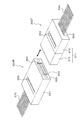
- FIG. 1 shows an outline of an optical coupling type optical connector (hereinafter referred to as “optical coupling connector”).
- This optical coupling connector is composed of a transmitting side optical connector 10 and a receiving side optical connector 20.
- the transmitting side optical connector 10 has a connector body 12 having a lens 11.
- the receiving side optical connector 20 has a connector body 22 having a lens 21.
- the optical fiber 15 is attached to the connector body 12 so that the emitting end thereof is located at the focal position on the optical axis of the lens 11.
- the optical fiber 25 is attached to the connector body 22 so that the incident end thereof is located at the focal position on the optical axis of the lens 21.
- the light emitted from the optical fiber 15 on the transmission side is incident on the lens 11 via the connector body 12, and the light shaped into collimated light is emitted from the lens 11.
- the light thus shaped into the collimated light is incident on the lens 21 and is condensed, and is incident on the incident end of the optical fiber 25 on the receiving side via the connector body 22.
- the light (optical signal) is transmitted from the optical fiber 15 on the transmitting side to the optical fiber 25 on the receiving side.
- the optical coupling connector as shown in FIG. 1 when the core diameter of the optical fiber is as small as about 8 ⁇ m ⁇ such as single mode, the deviation of the optical fiber optical path from the lens optical axis on the transmission side (optical axis deviation) is It has a great effect on the coupling loss of optical power at. Therefore, in the case of this optical coupling connector, high accuracy of parts is required in order to suppress the axis shift on the transmitting side, which results in an increase in cost.
- the focal length of the lens 11 on the transmitting side is lengthened so that the lens 11 emits the light source, that is, the optical fiber 15 on the transmitting side. It is possible to increase the distance to the edge.
- FIG. 2A shows a state in which the distance from the lens 11 to the light source P is not increased on the transmission side.
- the position of the light source P on the transmitting side deviates by A to P′
- the position of the condensing point Q on the receiving side shifts by Y to Q′.
- FIG. 2B shows a state in which the curvature of the lens 11 is loosened to increase the focal length and the distance from the lens 11 to the light source P is increased on the transmission side.
- the position of the light source P on the transmission side deviates by A to P′
- the position of the condensing point Q on the reception side deviates by Y′ to Q′, but Y′ becomes smaller than Y.
- Formula (1) below generally represents the relationship between the light source P and the condensing point Q.
- A is the positional displacement amount of the light source P
- B is the distance from the light source P to the lens 11
- X is the distance from the lens 21 to the condensing point Q
- the NA Numerical Aperture: numerical aperture
- the diameter of the collimated light is determined.
- NA numerical aperture: numerical aperture
- the maximum distance from the light source to the lens 11 is limited by NA.
- the accuracy of aligning the center of the light source with the center of the lens 11 at the time of manufacturing the component becomes low, so that the coupling loss of the optical power at the receiving side is reduced. This leads to an increase in the cost, a further increase in the cost for ensuring accuracy, or a decrease in usability due to an increase in the connector length.
- FIG. 4 shows a configuration example of the electronic device 100 and the optical cables 200A and 200B as the embodiment.
- the electronic device 100 includes an optical communication unit 101.
- the optical communication unit 101 includes a light emitting unit 102, an optical transmission line 103, a transmission side optical connector 300T as a receptacle, a reception side optical connector 300R as a receptacle, an optical transmission line 104, and a light receiving unit 105.
- Each of the optical transmission path 103 and the optical transmission path 104 can be realized by an optical fiber.
- the light emitting unit 102 includes a laser element such as a VCSEL (Vertical Cavity Surface Emitting LASER) or a light emitting element such as an LED (light emitting diode).
- the light emitting unit 102 converts an electric signal (transmission signal) generated by a transmission circuit (not shown) of the electronic device 100 into an optical signal.
- the optical signal emitted by the light emitting unit 102 is sent to the transmission side optical connector 300T via the optical transmission path 103.
- the light emitting section 102, the optical transmission path 103, and the transmission side optical connector 300T constitute an optical transmitter.
- the optical signal received by the receiving side optical connector 300R is sent to the light receiving unit 105 via the optical transmission path 104.
- the light receiving section 105 includes a light receiving element such as a photodiode.
- the light receiving unit 105 converts an optical signal sent from the receiving side optical connector 300R into an electric signal (reception signal) and supplies the electric signal to a reception circuit (not shown) of the electronic device 100.
- the receiving side optical connector 300R, the optical transmission line 104, and the light receiving unit 105 constitute an optical receiver.
- the optical cable 200A includes a receiving side optical connector 300R as a plug and a cable body 201A.
- the optical cable 200A transmits the optical signal from the electronic device 100 to another electronic device.
- the cable body 201A can be realized by an optical fiber.
- the one end of the optical cable 200A is connected to the transmission side optical connector 300T of the electronic device 100 by the reception side optical connector 300R, and the other end is connected to another electronic device (not shown).
- the transmission side optical connector 300T and the reception side optical connector 300R connected to each other form an optical coupling connector.
- the optical cable 200B includes a transmission side optical connector 300T as a plug and a cable body 201B.
- the optical cable 200B transmits an optical signal from another electronic device to the electronic device 100.
- the cable body 201B can be realized by an optical fiber.
- the one end of the optical cable 200B is connected to the receiving side optical connector 300R of the electronic device 100 by the transmitting side optical connector 300T, and the other end is connected to another electronic device (not shown).
- the transmission side optical connector 300T and the reception side optical connector 300R connected to each other form an optical coupling connector.
- the electronic device 100 is, for example, a mobile electronic device such as a mobile phone, a smartphone, a PHS, a PDA, a tablet PC, a laptop computer, a video camera, an IC recorder, a portable media player, an electronic notebook, an electronic dictionary, a calculator, and a portable game machine.
- Equipment and other electronic equipment such as desktop computers, display devices, television receivers, radio receivers, video recorders, printers, car navigation systems, game consoles, routers, hubs, optical line termination units (ONUs), etc. it can.
- the electronic device 100 constitutes a part or all of an electric product such as a refrigerator, a washing machine, a clock, an intercom, an air conditioner, a humidifier, an air purifier, a lighting device, a cooking appliance, or a vehicle as described below. You can
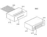
- FIG. 5 is a perspective view showing an example of a transmission side optical connector 300T and a reception side optical connector 300R that form an optical coupling connector.
- FIG. 6 is also a perspective view showing an example of the transmitting side optical connector 300T and the receiving side optical connector 300R, but is a view seen from the opposite direction to FIG.
- the illustrated example corresponds to parallel transmission of optical signals of a plurality of channels.
- the one corresponding to the parallel transmission of the optical signals of a plurality of channels is shown, the detailed description is omitted, but the one corresponding to the transmission of the optical signal of one channel can be similarly configured.
- the transmission side optical connector 300T includes a connector body 311 having a substantially rectangular parallelepiped appearance.
- the connector body 311 is configured by connecting a first optical section 312 and a second optical section 313.
- the connector body 311 is composed of the first and second optical parts 312 and 313 as described above, although not shown in FIGS. 5 and 6, the first lens can be easily manufactured. You can
- a plurality of optical fibers 330 respectively corresponding to the respective channels are connected to the back side of the first optical unit 312 in a state of being aligned in the horizontal direction.
- the tip end side of each optical fiber 330 is inserted and fixed in the optical fiber insertion hole 320.
- the optical fiber 330 constitutes a light emitter.
- an adhesive injection hole 314 having a rectangular opening is formed on the upper surface side of the first optical portion 312. From this adhesive injection hole 314, an adhesive for fixing the optical fiber 330 to the first optical portion 312 is inserted.
- a concave light emitting portion (light transmitting space) 315 having a rectangular opening is formed on the front surface side of the second optical portion 313, and the bottom portion of the light emitting portion 315 corresponds to each channel. Then, the plurality of second lenses (convex lenses) 316 are formed in a state of being aligned in the horizontal direction. This prevents the surface of the second lens 316 from accidentally hitting the mating connector or the like and being damaged.
- a position regulating portion 317 having a convex shape or a concave shape, which is a concave shape in the illustrated example, for alignment with the reception side optical connector 300R. ..
- the optical axis can be easily aligned when connecting to the receiving side optical connector 300R.
- 7 and 8 are perspective views showing a state in which the first optical section 312 and the second optical section 313 which form the connector main body 311 are separated. 7 and 8 are views seen from opposite directions.
- a plurality of first lenses (convex lenses) 318 are formed in a line in the horizontal direction corresponding to each channel.
- a concave space 319 having a rectangular opening is formed on the back side of the second optical unit 313.
- the first optical unit 312 and the second optical unit 313 are connected to form the connector body 311 (see FIGS. 5 and 6).
- the space 319 formed on the rear surface side of the second optical unit 313 is hermetically sealed on the front surface side of the first optical unit 312 to form a hermetically sealed space.
- the first lens 318 formed on the front surface side of the first optical unit 312 is in a state of being located in the closed space 319.
- the receiving side optical connector 300R includes a connector body 351 having a substantially rectangular parallelepiped appearance.
- a plurality of optical fibers 370 corresponding to the respective channels are connected.
- each optical fiber 370 has its tip end inserted and fixed in the optical fiber insertion hole 356.
- an adhesive injection hole 352 having a rectangular opening is formed on the upper surface side of the connector body 351. An adhesive for fixing the optical fiber 370 to the connector body 351 is inserted from the adhesive injection hole 352.
- a concave light incident portion (light transmission space) 353 having a rectangular opening is formed on the front surface side of the connector body 351, and a lens 354 corresponding to each channel is formed on the bottom portion of the light incident portion 353. Are located. This prevents the surface of the lens 354 from accidentally hitting the mating connector or the like and being damaged.
- a position regulating portion 355 having a concave shape or a convex shape, in the illustrated example, a convex shape for aligning with the transmission side optical connector 300T is integrally formed.
- the position restricting portion 355 is not limited to the one integrally formed with the connector body 351, and a pin may be used or another method may be used.
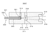
- FIG. 9 is a sectional view showing an example of the transmitting side optical connector 300T.
- the position restricting portion 317 (see FIG. 5) is omitted.
- the transmission side optical connector 300T will be further described with reference to FIG.
- the transmitting-side optical connector 300T includes a connector body 311 configured by connecting a first optical section 312 and a second optical section 313.
- the first optical portion 312 is made of a light-transmitting material such as synthetic resin or glass, or a material such as silicon that transmits a specific wavelength, and has a configuration of a ferrule with a lens.
- the first optical unit 312 By thus configuring the first optical unit 312 as a ferrule with a lens, the optical axes of the optical fiber 330 and the first lens 318 can be easily aligned. Further, since the first optical unit 312 is configured as a ferrule with a lens in this way, even in the case of multiple channels, multichannel communication can be easily realized by simply inserting the optical fiber 330 into the ferrule.
- the first optical unit 312 On the front surface side of the first optical unit 312, a plurality of first lenses 318 corresponding to the respective channels are integrally formed in a state of being aligned in the horizontal direction. As a result, the positional accuracy of the first lens 318 with respect to the core 331 of the optical fiber 330 installed in the first optical unit 312 can be simultaneously improved in a plurality of channels.
- the first optical unit 312 is provided with a plurality of optical fiber insertion holes 320 extending from the back side to the front side in a state of being aligned in the horizontal direction so as to be aligned with the first lens 318 of each channel.
- the optical fiber 330 has a double structure of a core 331 at the central portion that serves as an optical path and a clad 332 that covers the core.
- the optical fiber insertion hole 320 of each channel is formed so that the core 331 of the optical fiber 330 inserted therein and the optical axis of the corresponding first lens 318 coincide with each other. Further, the optical fiber insertion hole 320 of each channel is adjusted so that the bottom position thereof, that is, the contact position of the tip (emission end) when the optical fiber 330 is inserted matches the focal position of the first lens 318. , Molded.
- an adhesive injection hole 314 extending downward from the upper surface side is formed so as to communicate with the vicinity of the bottom position of the plurality of optical fiber insertion holes 320 arranged in the horizontal direction.
- the adhesive 321 is injected around the optical fiber 330 from the adhesive injection hole 314, so that the optical fiber 330 is fixed to the first optical portion 312.
- the adhesive 321 is a light transmissive agent and is injected between the tip of the optical fiber 330 and the bottom position of the optical fiber insertion hole 320, whereby reflection can be reduced.
- the second optical unit 313 is made of, for example, a light transmissive material such as synthetic resin or glass, or a material such as silicon that transmits a specific wavelength.
- the second optical section 313 is connected to the first optical section 312 to form the connector body 311. If the coefficients of thermal expansion are made uniform, the optical path shift due to the strain in the two optical parts when the heat changes can be suppressed, so that the material of the second optical part 313 is the same as the material of the first optical part 312. It is preferable that there is one, but another material may be used.
- a concave light emitting portion (light transmission space) 315 is formed on the front surface side of the second optical portion 313. Then, a plurality of second lenses 316 corresponding to the respective channels are integrally formed in the second optical unit 313 so as to be located at the bottom portion of the light emitting unit 315 in a state where they are aligned in the horizontal direction. Has been done. Thereby, the positional accuracy of the second lens 316 with respect to the second optical unit 313 can be improved.
- a concave space 319 is formed on the back side of the second optical unit 313.
- This space 319 is hermetically sealed on the front side of the first optical unit 312 to form a hermetically sealed space.
- the first lens 318 of each channel formed on the front surface side of the first optical unit 312 is in a state of being located in this closed space 319.
- the connector body 311 is configured by connecting the first optical section 312 and the second optical section 313.
- this connection method a method in which a concave portion is newly provided on one side and a convex portion is newly provided on the other side such as a boss, and fitting is performed, or a method of aligning the optical axis positions of the lenses with an image processing system or the like and adhering and fixing the lenses is adopted. obtain.
- the first lens 318 has a function of converging the light emitted from the optical fiber 330 which is a light emitting body.
- the second lens 316 has a function of shaping the light converged by the first lens 318 into collimated light and emitting the light.
- the light emitted from the emission end of the optical fiber 330 with a predetermined NA is incident on the first lens 318 and converged (angle is narrowed), and the converged light is incident on the second lens 316.
- the collimated light is shaped and emitted.
- FIG. 10 is a sectional view showing an example of the receiving side optical connector 300R.
- the position restricting portion 355 (see FIGS. 5 and 6) is omitted.
- the receiving side optical connector 300R will be further described with reference to FIG.
- the receiving side optical connector 300R includes a connector body 351.
- the connector body 351 is made of, for example, a light-transmitting material such as synthetic resin or glass, or a material such as silicon that transmits a specific wavelength, and has a configuration of a ferrule with a lens.
- a concave light incident portion (light transmission space) 353 is formed on the front surface side of the connector body 351.
- a plurality of lenses (convex lenses) 354 corresponding to the respective channels are integrally formed in the connector main body 351 so as to be located at the bottom of the light incident portion 353 in a state of being aligned in the horizontal direction. ..
- the connector main body 351 is provided with a plurality of optical fiber insertion holes 356 extending from the back side to the front side in line with the lens 354 of each channel in a horizontal direction.
- the optical fiber 370 has a double structure of a core 371 in the central portion that serves as an optical path and a clad 372 that covers the periphery thereof.
- the optical fiber insertion hole 356 of each channel is formed so that the optical axis of the lens 354 corresponding to the core 371 of the optical fiber 370 inserted therein matches. Further, the optical fiber insertion hole 356 of each channel is formed so that its bottom position, that is, the contact position of its tip (incident end) when the optical fiber 370 is inserted matches the focal position of the lens 354. ing.
- an adhesive injection hole 352 extending downward from the upper surface side is formed in the connector body 351 so as to communicate with the vicinity of the bottom positions of the plurality of optical fiber insertion holes 356 which are aligned in the horizontal direction. .. After the optical fiber 370 is inserted into the optical fiber insertion hole 356, the adhesive 357 is injected around the optical fiber 370 from the adhesive injection hole 352, so that the optical fiber 370 is fixed to the connector body 351.
- the lens 354 has a function of condensing the incident collimated light.
- the collimated light is incident on the lens 354 and is condensed, and the condensed light is incident on the incident end of the optical fiber 370 which is the light receiving body with a predetermined NA.
- FIG. 11 shows a cross-sectional view of a transmission side optical connector 300T and a reception side optical connector 300R that form an optical coupling connector.
- the illustrated example shows a state in which the transmission side optical connector 300T and the reception side optical connector 300R are connected.
- the light transmitted through the optical fiber 330 is emitted from the emission end of the optical fiber 330 with a predetermined NA.
- the emitted light enters the first lens 318 and is converged.
- the converged light is incident on the second lens 316, is shaped into collimated light, and is emitted toward the reception side optical connector 300R.
- the light emitted from the transmitting side optical connector 300T is incident on the lens 354 and is condensed. Then, the condensed light is incident on the incident end of the optical fiber 370 and is sent through the optical fiber 370.
- the transmission side optical connector 300T converges the light emitted from the optical fiber 330 as the light emitting body by the first lens 318, and collects the converged light into the second light.
- the light is shaped into collimated light by the lens 316 and emitted. Therefore, it is possible to prevent the distance from the optical fiber 330 from the second lens 316 from becoming long and to control the diameter of the light from the optical fiber 330 so as to be within the diameter of the second lens 316.
- By increasing the focal length of the lens 316 it is possible to reduce the coupling loss of the optical power on the receiving side with respect to the axis shift on the transmitting side.
- the angle of the light incident on the second lens 316 becomes gentle, and the curvature of the second lens 316 also becomes gentle so that the transmitting side has a small curvature.
- the deviation of the light-collecting point on the receiving side with respect to the axis deviation of is suppressed.
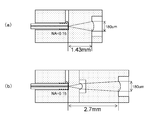
- the mode field diameter (MFD) of the optical fiber is 8 ⁇ m, and an optical system having an NA of the optical fiber of 0.15 and a collimator aperture of 180 ⁇ m is used.
- FIG. 12A shows an example of the configuration of a normal transmission side optical connector.
- FIG.12(b) has shown the structural example of the transmission side optical connector by this technique.
- the structure of the receiving side optical connector is the same as the structure of the conventional transmitting side optical connector shown in FIG.
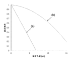
- the graph in FIG. 13 shows a simulation result of the coupling efficiency of light input to the optical fiber on the receiving side.
- the horizontal axis represents the axis shift amount, which indicates the shift amount when the light source shifts in the direction perpendicular to the optical axis, and the vertical axis indicates the light coupling efficiency on the receiving side.
- the solid line (a) shows the relationship between the amount of axis deviation and the coupling efficiency when the normal transmission-side optical connector shown in FIG. 12(a) is used.
- the solid line (b) shows the relationship between the amount of axial deviation and the coupling efficiency when the transmission side optical connector according to the present technology shown in FIG. 12(b) is used.
- the MFD of the optical fiber is 8 ⁇ m, for example, when the amount of axis deviation is 5 ⁇ m, when the normal optical connector on the transmission side shown in FIG. Power loss occurs.
- the transmission side optical connector according to the present technology shown in FIG. 12B is used, the power loss is about 10% from the solid line (b), and the power loss is significantly reduced.
- FIG. 14 is a cross-sectional view showing a transmitting side optical connector 300T-1 as another configuration example 1. 14, parts corresponding to those in FIG. 9 are designated by the same reference numerals, and detailed description thereof will be appropriately omitted.
- the first lens 318 is formed not on the front side of the first optical section 312 but on the bottom part of the space 319 formed on the back side of the second optical section 313. It
- the space 319 formed on the back side of the second optical section 313 is on the front side of the first optical section 312. It becomes a closed space by being sealed. Therefore, also in this transmission side optical connector 300T-1, as in the transmission side optical connector 300T of FIG. 9, the first lens 318 is placed in the closed space 319, and dust, dust, etc. on the surface thereof. Can be prevented in advance.
- FIG. 15 is a sectional view showing a transmitting side optical connector 300T-2 as another configuration example 2. 15, parts corresponding to those in FIG. 9 are designated by the same reference numerals, and detailed description thereof will be appropriately omitted.
- a second first lens (convex lens) 322 is formed in the bottom portion of the space 319 formed on the back side of the second optical unit 313.
- the light emitted from the emission end of the optical fiber 330 with a predetermined NA is incident on the first lens 318 and is converged (angle is narrowed), and the converged light is Is incident on the second first lens 322 and further converged (angle is narrowed), and the converged light is incident on the second lens 316, shaped into collimated light, and emitted.
- the spherical height of each of the two first lenses 318 and 322 can be lowered, It is possible to improve the ease of molding the lens.
- the two first lenses 318 and 322 are in a state of being located in the closed space 319 and dust on the surface thereof. It is possible to prevent dust from adhering.
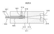
- FIG. 16 is a sectional view showing a transmitting side optical connector 300T-3 as another configuration example 3. 16, parts corresponding to those in FIG. 9 are designated by the same reference numerals, and detailed description thereof will be appropriately omitted.
- the first lens 318 is formed not at the front surface side of the first optical portion 312 but at the deepest bottom portion of the optical fiber insertion hole 320. By thus forming the first lens 318 in the bottom portion of the optical fiber insertion hole 320, it is possible to further improve the accuracy of optical axis alignment between the optical fiber 330 and the first lens 318.
- the tip of the optical fiber 330 is not abutted against the bottom portion of the fiber insertion hole 320, and a constant distance is maintained from this bottom portion, that is, the first lens 318. It is necessary to fix it at the focal position of.
- the optical fiber 330 when the optical fiber 330 is bonded and fixed to the first optical portion 312, if the adhesive 321 enters between the tip of the optical fiber 330 and the first lens 318, the optical characteristics change.
- the formation position of the adhesive injection hole 314 for injecting the adhesive 321 is to avoid the tip of the optical fiber 330 so that the adhesive 321 does not enter between the tip of the optical fiber 330 and the first lens 318. Need to
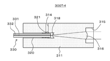
- FIG. 17 is a sectional view showing a transmitting side optical connector 300T-4 as another configuration example 4. 17, parts corresponding to those in FIGS. 9 and 16 are designated by the same reference numerals, and detailed description thereof will be appropriately omitted.
- the connector main body 311 is composed of one optical section. This is possible because forming the first lens 318 at the bottom of the optical fiber insertion hole 320 eliminates the need to create a space 319 in the optical section.
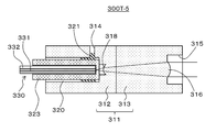
- FIG. 18 is a sectional view showing a transmitting side optical connector 300T-5 as another configuration example 5. 18, parts corresponding to those in FIGS. 9 and 16 are designated by the same reference numerals, and detailed description thereof will be appropriately omitted.
- the transmission side optical connector 300T-5 the diameter of the optical fiber insertion hole 320 formed in the first optical section 312 is increased. Then, the ferrule 323 to which the optical fiber 330 is fixed by abutting in advance is inserted into the optical fiber insertion hole 320, and is fixed by the adhesive 321. With such a configuration, it becomes easy to keep the tip of the optical fiber 330 at a constant distance from the first lens 318.
- FIG. 19 is a sectional view showing a transmitting side optical connector 300T-6 as another configuration example 6. 19, parts corresponding to those in FIGS. 9, 16 and 18 are designated by the same reference numerals, and detailed description thereof will be appropriately omitted.
- the connector main body 311 is composed of one optical section. Others are configured similarly to the transmission side optical connector 300T-5 in FIG.
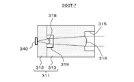
- FIG. 20 is a cross-sectional view showing a transmitting side optical connector 300T-7 as another configuration example 7. 20, parts corresponding to those in FIG. 9 are designated by the same reference numerals, and detailed description thereof will be appropriately omitted.
- the transmitting side optical connector 300T-7 the light emitting body fixed to the first optical unit 312 is not the optical fiber 330 but a light emitting element 340 such as VCSEL (Vertical Cavity Surface Emitting LASER). Is.
- VCSEL Vertical Cavity Surface Emitting LASER
- a plurality of light emitting elements 340 are fixed on the back surface side of the first optical unit 312, aligned in the horizontal direction, in alignment with the first lens 318 of each channel. Then, in this case, the light emitting element 340 of each channel is fixed such that the emitting portion thereof coincides with the optical axis of the corresponding first lens 318. Further, in this case, the thickness and the like of the first optical unit 312 in the optical axis direction are set such that the emitting portions of the light emitting elements 340 of the respective channels match the focal positions of the corresponding first lenses 318. ..
- the light emitted from the emitting portion of the light emitting element 340 with a predetermined NA is incident on the first lens 318 and is converged (angle is narrowed), and the converged light is Is incident on the second lens 316, shaped into collimated light, and emitted.
- FIG. 21 is a sectional view showing a transmitting side optical connector 300T-8 as another configuration example 8. 21, parts corresponding to those in FIGS. 9 and 20 are designated by the same reference numerals, and detailed description thereof will be omitted as appropriate.
- the substrate 341 on which the light emitting element 340 is mounted is fixed to the lower surface side of the connector body 311. In this case, a plurality of light emitting elements 340 are mounted on the substrate 341 so as to be aligned in the horizontal direction so as to match the first lens 318 of each channel.
- the first optical portion 312 has a light emitting element placement hole 324 extending upward from the lower surface side. Then, in order to change the optical path of the light from the light emitting element 340 of each channel to the direction of the corresponding first lens 318, the bottom portion of the light emitting element placement hole 324 is an inclined surface, and the mirror 342 is formed on this inclined surface. Are arranged. As for the mirror 342, it is conceivable that not only the separately generated mirror 342 is fixed to the inclined surface, but also the inclined surface is formed by vapor deposition or the like.
- the position of the substrate 341 is adjusted and fixed so that the emission parts of the light emitting elements 340 of the respective channels are aligned with the optical axes of the corresponding first lenses 318. Further, in this case, the formation position of the first lens 318 and the formation position of the light emitting element disposition hole 324 are adjusted so that the emission parts of the light emitting elements 340 of the respective channels match the focal positions of the corresponding first lenses 318. -The length etc. are set.
- the light emitted from the emitting portion of the light emitting element 340 with a predetermined NA is changed in its optical path by the mirror 342 and then is incident on the first lens 318 and converged (the angle is narrowed). This converged light is incident on the second lens 316, shaped into collimated light, and emitted.
- the substrate 341 on which the light emitting element 340 is mounted is fixed to the connector body 311, an optical fiber is not required when transmitting an optical signal from the light emitting element 340, and the cost can be reduced. .. Further, since the light from the light emitting element 340 placed on the substrate 341 is changed in the optical path by the mirror 342 and incident on the first lens 318, the mounting is facilitated and the degree of design freedom is increased. it can.
- FIG. 22 is a sectional view showing a transmitting side optical connector 300T-9 as another configuration example 9. 22, parts corresponding to those in FIGS. 9 and 21 are designated by the same reference numerals, and detailed description thereof will be omitted as appropriate.
- the first optical portion 312 has optical fiber insertion holes 325 extending upward from the lower surface side aligned with the first lens 318 of each channel in the horizontal direction. Are formed in multiple.
- each optical fiber insertion hole 325 In order to change the optical path of the light from the optical fiber 330 inserted into each optical fiber insertion hole 325 toward the corresponding first lens 318, the bottom portion of each optical fiber insertion hole 325 is an inclined surface. A mirror 342 is arranged on the inclined surface. Further, each optical fiber insertion hole 325 is formed so that the core 331 of the optical fiber 330 inserted therein and the optical axis of the corresponding first lens 318 coincide with each other.
- the optical fiber 330 of the corresponding channel is inserted into each optical fiber insertion hole 325, and is fixed by, for example, injecting an adhesive agent (not shown) around the optical fiber 330.
- the optical fiber 330 has its tip (emission end) aligned with the focal position of the corresponding first lens 318, and therefore has its tip (emission end) located at a constant distance from the mirror 342. , Its insertion position is set.
- the light emitted from the emission end of the optical fiber 330 with a predetermined NA is changed in the optical path by the mirror 342 and then is incident on the first lens 318 and converged (the angle is narrowed). This converged light is incident on the second lens 316, shaped into collimated light, and emitted.
- the first optical unit 312 since the first optical unit 312 has the configuration of a ferrule with a lens, the optical axes of the optical fiber 330 and the first lens 318 can be easily adjusted. Further, in the case of this configuration example, since the optical path of the light from the optical fiber 330 is changed by the mirror 342, mounting is facilitated and the degree of freedom in design can be increased.
- FIG. 23 is a cross-sectional view showing a transmitting side optical connector 300T-10 as another configuration example 10. 23, parts corresponding to those in FIGS. 9, 18 and 22 are denoted by the same reference numerals, and detailed description thereof will be appropriately omitted.
- the transmission side optical connector 300T-10 the diameter of the optical fiber insertion hole 325 formed in the first optical portion 312 is increased. Then, the ferrule 323 to which the optical fiber 330 is fixed by abutting in advance is inserted into the optical fiber insertion hole 325, and is fixed by, for example, an adhesive (not shown). With such a configuration, it becomes easy to keep the tip position of the optical fiber 330 at a constant distance from the mirror 342.
- FIG. 24 shows an optical coupling connector that uses convergent light (light bent in the light collecting direction) instead of collimated light. 24, parts corresponding to those in FIG. 3 are designated by the same reference numerals.
- An optical connector including a connector body having a first lens that converges light emitted from a light-emitting body and a second lens that shapes and emits light converged by the first lens.
- the connector body has a closed space, The optical connector according to (1), wherein the first lens is located in the closed space.
- the connector body comprises a first optical section on which the light emitted from the light emitting body is incident and a second optical section having the second lens, and the connector body according to (1) to (3) above.
- the optical connector according to any one.
- the light emitter is an optical fiber
- the optical connector according to (7), wherein the insertion hole is an insertion hole for inserting a ferrule in which the optical fiber is inserted and fixed.
- the connector body has an optical path changing portion for changing an optical path at a bottom portion of the insertion hole, and the light emitted from the optical fiber is changed in the optical path changing portion so that the first lens is provided.
- the optical connector according to any one of (6) to (8), which is incident on the optical connector.
- the optical connector according to any one of (1) to (5), wherein the light emitter is a light emitting element that converts an electric signal into an optical signal.
- the light emitting element is connected to the connector body, The optical connector according to (10), wherein the light emitted from the light emitting element is incident on the first lens without changing the optical path.
- the connector body has an optical path changing portion for changing the optical path, The light emitting element is fixed to the substrate, The optical connector according to (10), wherein the light emitted from the light emitting element has its optical path changed by the optical path changing unit and is incident on the first lens.
- the connector body is Made of light transmissive material, The optical connector according to any one of (1) to (13), which integrally has the first lens and the second lens.
- the connector body has a concave light emitting portion
- the said 2nd lens is an optical connector in any one of said (1) to (15) located in the bottom part of the said light emission part.
- the connector body has integrally a convex or concave position regulating portion on the front side for aligning with the connector of the connection partner side.
- the optical connector described.
- the optical connector is An optical cable comprising a connector body having a first lens that converges light emitted from a light-emitting body and a second lens that shapes and emits light converged by the first lens.
- An electronic device having an optical connector as a receptacle The optical connector is An electronic device comprising: a connector body having a first lens that converges light emitted from a light-emitting body and a second lens that shapes and emits light converged by the first lens.
- Optical communication unit 102... Light emitting unit 103, 104... Optical transmission line 105... Light receiving unit 200A, 200B... Optical cable 201A, 201B... Cable body 300T , 300T-1 to 300T-10... Transmitting side optical connector 300R... Receiving side optical connector 311... Connector body 312... First optical section 313... Second optical section 314... Adhesive injection hole 315... Light emitting part 316... Second lens 317... Position regulating part 318... First lens 319... Space (closed space) 320... Optical fiber insertion hole 321... Adhesive 322... First lens 323... Ferrule 324... Light emitting element placement hole 325... Optical fiber insertion hole 330...
- Optical fiber 331 ... Core 340... Light emitting element 341... Substrate 342... Mirror... 332... Clad 351... Connector body 352; Adhesive insertion hole 353... Light incident part 354... -Lens 355... Position control part 356... Optical fiber insertion hole 357... Adhesive 370... Optical fiber 371... Core 372... Clad
Abstract
This optical connector favorably mitigates receiving-side optical power coupling loss due to transmission-side axial misalignment. The optical connector is provided with a connector body which holds a first lens and a second lens. The first lens converges light emitted from a light-emitting body. The second lens forms and emits the light converged by the first lens. The second lens forms the light emitted from the first lens into collimated light, for example. While suppressing increases in the distance from the light-emitting body to the second lens and restricting the diameter of the light from the light-emitting body to within the second lens diameter, it is possible to lengthen the focus distance of the second lens and to mitigate receiving-side optical power coupling loss due to axial misalignment on the transmission side.
Description
本技術は、光コネクタ、光ケーブルおよび電子機器に関する。詳しくは、軸ずれに対する光のパワーロスを緩和可能な光コネクタ等に関する。
The present technology relates to optical connectors, optical cables and electronic devices. More specifically, the present invention relates to an optical connector or the like that can alleviate the power loss of light with respect to axis deviation.
従来、光結合方式による光コネクタ、いわゆる光結合コネクタが提案されている(例えば、特許文献1参照)。光結合コネクタは、各光ファイバの先に光軸を合わせてそれぞれレンズを装着し、光信号を対向するレンズ間で平行光として伝送する方式である。この光結合コネクタでは、光ファイバ同士が非接触の状態で光結合されるため、光ファイバ間に侵入したゴミ等による伝送品質への悪影響も抑えられ、頻繁なかつ丁寧なクリーニングは不要になる。
Conventionally, an optical connector using an optical coupling method, a so-called optical coupling connector has been proposed (for example, refer to Patent Document 1). The optical coupling connector is a system in which the optical axis is aligned with the end of each optical fiber and a lens is attached to each of the optical fibers to transmit an optical signal as parallel light between the opposing lenses. In this optical coupling connector, since the optical fibers are optically coupled in a non-contact state, adverse effects on transmission quality due to dust entering between the optical fibers are suppressed, and frequent and careful cleaning is not required.
光結合方式の光コネクタにおいては、例えば、光ファイバのコア径がシングルモードのように非常に小さい場合、送信側におけるレンズ光軸と光ファイバ光路のずれ、いわゆる軸ずれが受信側での大きな光パワーの結合ロスに繋がるという問題があった。
In an optical coupling type optical connector, for example, when the core diameter of the optical fiber is very small as in single mode, a deviation between the lens optical axis and the optical fiber optical path on the transmitting side, so-called axial deviation, is a large optical signal on the receiving side. There was a problem that it led to a power loss.
本技術の目的は、送信側での軸ずれに対する受信側での光パワーの結合ロスを良好に緩和することにある。
The purpose of this technology is to satisfactorily reduce the coupling loss of the optical power on the receiving side against the axis deviation on the transmitting side.
本技術の概念は、
発光体から出射された光を収束する第1のレンズと該第1のレンズで収束された光を成形して出射する第2のレンズを持つコネクタ本体を備える
光コネクタにある。 The concept of this technology is
An optical connector includes a connector body having a first lens that converges light emitted from a light-emitting body and a second lens that shapes and emits light converged by the first lens.
本技術においては、第1のレンズと第2のレンズを持つコネクタ本体を備えるものである。ここで、第1のレンズでは、発光体から出射される光が収束される。また、第2のレンズでは、第1のレンズで収束された光が成形されて出射される。例えば、第1のレンズは1つまたは2つ以上のレンズからなる、ようにされてもよい。また、例えば、第2のレンズは、第1のレンズから出射される光をコリメート光に成形するためのレンズである、ようにされてもよい。
According to the present technology, a connector main body having a first lens and a second lens is provided. Here, in the first lens, the light emitted from the light emitting body is converged. Further, the second lens shapes and emits the light converged by the first lens. For example, the first lens may consist of one or more lenses. Also, for example, the second lens may be a lens for shaping the light emitted from the first lens into collimated light.
このように本技術においては、発光体から出射された光を第1のレンズで収束し、この収束された光を第2のレンズで成形して出射するものである。そのため、発光体から第2のレンズまでの距離が長くなることを抑制すると共に発光体からの光の径を第2のレンズ径内に収まるように規制しつつ、第2のレンズの焦点距離を長くして、送信側での軸ずれに対する受信側での光パワーの結合ロスを緩和することが可能となる。
As described above, in the present technology, the light emitted from the light-emitting body is converged by the first lens, and the converged light is shaped by the second lens and emitted. Therefore, it is possible to prevent the distance from the light emitting body to the second lens from becoming long and to control the diameter of the light from the light emitting body so as to be within the second lens diameter, while changing the focal length of the second lens. By making the length longer, it becomes possible to reduce the coupling loss of the optical power on the receiving side against the axis deviation on the transmitting side.
なお、本技術において、例えば、コネクタ本体は密閉空間を有し、第1のレンズは密閉空間に位置する、ようにされてもよい。このように第1のレンズが密閉空間に位置するようにされることで、第1のレンズの表面への塵、埃などの付着を未然に防止できる。
Note that, in the present technology, for example, the connector body may have a closed space, and the first lens may be located in the closed space. By thus positioning the first lens in the closed space, it is possible to prevent dust and dirt from adhering to the surface of the first lens.
また、本技術において、例えば、コネクタ本体は、発光体から出射された光が入射される第1の光学部と、第2のレンズを持つ第2の光学部からなる、ようにされてもよい。この場合、例えば、第1のレンズは、第1の光学部および/または第2の光学部に含まれる、ようにされてもよい。このようにコネクタ本体が第1、第2の光学部からなるようにされることで、第1のレンズの製造などを容易に行うことができる。
Further, in the present technology, for example, the connector main body may be configured to include a first optical unit on which the light emitted from the light emitting body is incident and a second optical unit having a second lens. .. In this case, for example, the first lens may be included in the first optical unit and/or the second optical unit. Since the connector main body is made up of the first and second optical parts in this way, it is possible to easily manufacture the first lens.
また、本技術において、例えば、発光体は光ファイバであり、コネクタ本体は、光ファイバを挿入する挿入孔を有する、ようにされてもよい。このようにコネクタ本体が発光体としての光ファイバを挿入する挿入孔を有するようにされることで、光ファイバと第1のレンズとの光軸合わせを容易に行うことができる。
Further, in the present technology, for example, the light emitting body may be an optical fiber, and the connector body may have an insertion hole into which the optical fiber is inserted. Since the connector body has the insertion hole into which the optical fiber as the light emitting body is inserted, the optical axis of the optical fiber and the first lens can be easily aligned.
この場合、例えば、第1のレンズは、挿入孔の底部分に存在する、ようにされてもよい。このように第1のレンズが挿入孔の底部分に存在するようにされることで、光ファイバと第1のレンズとの光軸合わせの精度をより高めることが可能となる。そして、この場合、挿入孔は、光ファイバが挿入固定されたフェルールを挿入するための挿入孔である、ようにされてもよい。これにより、光ファイバと第1のレンズの間の光軸方向の距離を一定に保つことが容易となる。
In this case, for example, the first lens may be present at the bottom portion of the insertion hole. Since the first lens is present in the bottom portion of the insertion hole in this way, it is possible to further improve the accuracy of optical axis alignment between the optical fiber and the first lens. And in this case, the insertion hole may be an insertion hole for inserting the ferrule in which the optical fiber is inserted and fixed. This makes it easy to keep the distance between the optical fiber and the first lens in the optical axis direction constant.
また、この場合、例えば、コネクタ本体は、挿入孔の底部分に光路を変更するための光路変更部を持ち、光ファイバから出射された光は光路変更部で光路変更されて第1のレンズに入射される、ようにされてもよい。このように光路変更部が設けられることで、設計自由度を上げることができる。そして、この場合、挿入孔は、光ファイバが挿入固定されたフェルールを挿入するための挿入孔である、ようにされてもよい。これにより、光ファイバと光路変更部の間の光軸方向の距離を一定に保つことが容易となる。
Further, in this case, for example, the connector main body has an optical path changing portion for changing the optical path at the bottom portion of the insertion hole, and the light emitted from the optical fiber is changed in the optical path by the optical path changing portion to the first lens. It may be made incident. By providing the optical path changing unit in this way, the degree of freedom in design can be increased. And in this case, the insertion hole may be an insertion hole for inserting the ferrule in which the optical fiber is inserted and fixed. This makes it easy to keep the distance between the optical fiber and the optical path changing unit constant in the optical axis direction.
また、本技術において、例えば、発光体は、電気信号を光信号に変換する発光素子である、ようにされてもよい。このように発光体が発光素子とされることで、発光素子からの光信号を伝送する際に、光ファイバが不要となり、コストの低減が可能となる。
Further, in the present technology, for example, the light emitting body may be configured to be a light emitting element that converts an electric signal into an optical signal. By using the light emitting element as the light emitting element in this way, an optical fiber is not required when transmitting an optical signal from the light emitting element, and the cost can be reduced.
この場合、例えば、発光素子はコネクタ本体に接続されており、発光素子から出射された光は光路変更されずに第1のレンズに入射される、ようにされてもよい。また、例えば、コネクタ本体は光路を変更するための光路変更部を持ち、発光素子は基板に固定されており、発光素子から出射された光は光路変更部で光路変更されて第1のレンズに入射される、ようにされてもよい。このように基板に固定された発光素子からの光を光路変更部で光路変更して第1のレンズに入射する構成とされることで、実装が容易となり、設計自由度を上げることができる。
In this case, for example, the light emitting element may be connected to the connector body, and the light emitted from the light emitting element may enter the first lens without changing the optical path. In addition, for example, the connector body has an optical path changing unit for changing the optical path, the light emitting element is fixed to the substrate, and the light emitted from the light emitting element is changed in the optical path by the optical path changing unit to the first lens. It may be made incident. As described above, the light from the light emitting element fixed to the substrate is changed in the optical path by the optical path changing unit and is incident on the first lens, so that the mounting is facilitated and the degree of design freedom can be increased.
また、本技術において、例えば、コネクタ本体は、光透過性材料からなり、第1のレンズおよび第2のレンズを一体的に持つ、ようにされてもよい。この場合、コネクタ本体に対する第1のレンズおよび第2のレンズの位置精度を高めることが可能となる。
Further, in the present technology, for example, the connector body may be made of a light transmissive material and integrally have the first lens and the second lens. In this case, the positional accuracy of the first lens and the second lens with respect to the connector body can be improved.
また、本技術において、例えば、コネクタ本体は、第1のレンズと第2のレンズの組み合わせを複数持つ、ようにされてもよい。このようにコネクタ本体が第1のレンズと第2のレンズの組み合わせを複数持つような構成とされることで、多チャネル化が容易に可能となる。
Further, in the present technology, for example, the connector body may have a plurality of combinations of the first lens and the second lens. In this way, the connector main body is configured to have a plurality of combinations of the first lens and the second lens, so that the number of channels can be easily increased.
また、本技術において、例えば、コネクタ本体は凹状の光出射部を持ち、第2のレンズは光出射部の底部分に位置する、ようにされてもよい。このように第2のレンズが光出射部の底部分に位置するようにされることで、第2のレンズの表面が相手側のコネクタ等に不用意に当たって傷つくことを防止できる。
Further, in the present technology, for example, the connector body may have a concave light emitting portion, and the second lens may be located at the bottom portion of the light emitting portion. By thus positioning the second lens at the bottom portion of the light emitting portion, it is possible to prevent the surface of the second lens from being inadvertently hit on the mating connector or the like and damaged.
また、本技術において、例えば、コネクタ本体は、前面側に、接続相手側のコネクタとの位置合わせをするための凸状あるいは凹状の位置規制部を一体的に持つ、ようにされてもよい。これにより、相手側のコネクタとの接続時の光軸合わせが容易となる。
Further, in the present technology, for example, the connector body may be integrally provided on the front surface side with a convex or concave position restriction portion for aligning with the connector of the connection partner. This facilitates optical axis alignment when connecting to the mating connector.
また、本技術において、例えば、発光体をさらに備える、ようにされてもよい。このように発光体を備える構成とされることで、発光体を装着する手間を省くことが可能となる。
Further, in the present technology, for example, a light emitting body may be further provided. With such a configuration including the light emitting body, it is possible to save the trouble of mounting the light emitting body.
また、本技術の他の概念は、
プラグとしての光コネクタを有する光ケーブルであって、
上記光コネクタは、
発光体から出射された光を収束する第1のレンズと該第1のレンズで収束された光を成形して出射する第2のレンズを持つコネクタ本体を備える
光ケーブルにある。 In addition, another concept of the present technology is
An optical cable having an optical connector as a plug,
The optical connector is
An optical cable includes a connector body having a first lens that converges light emitted from a light-emitting body and a second lens that shapes and emits light converged by the first lens.
また、本技術の他の概念は、
レセプタクルとしての光コネクタを有する電子機器であって、
上記光コネクタは、
発光体から出射された光を収束する第1のレンズと該第1のレンズで収束された光を成形して出射する第2のレンズを持つコネクタ本体を備える
電子機器にある。 In addition, another concept of the present technology is
An electronic device having an optical connector as a receptacle,
The optical connector is
An electronic apparatus includes a connector main body having a first lens that converges light emitted from a light-emitting body and a second lens that shapes and emits light converged by the first lens.
以下、発明を実施するための形態(以下、「実施の形態」とする)について説明する。なお、説明は以下の順序で行う。
1.実施の形態
2.変形例 Hereinafter, modes for carrying out the invention (hereinafter, referred to as "embodiments") will be described. The description will be given in the following order.
1.Embodiment 2. Modification
1.実施の形態
2.変形例 Hereinafter, modes for carrying out the invention (hereinafter, referred to as "embodiments") will be described. The description will be given in the following order.
1.
<1.実施の形態>
[本技術の基本説明]
まず、本技術に関する技術について説明をする。図1は、光結合方式の光コネクタ(以下、「光結合コネクタ」という)の概要を示している。この光結合コネクタは、送信側光コネクタ10と受信側光コネクタ20で構成されている。 <1. Embodiment>
[Basic explanation of this technology]
First, a technique related to the present technique will be described. FIG. 1 shows an outline of an optical coupling type optical connector (hereinafter referred to as “optical coupling connector”). This optical coupling connector is composed of a transmitting sideoptical connector 10 and a receiving side optical connector 20.
[本技術の基本説明]
まず、本技術に関する技術について説明をする。図1は、光結合方式の光コネクタ(以下、「光結合コネクタ」という)の概要を示している。この光結合コネクタは、送信側光コネクタ10と受信側光コネクタ20で構成されている。 <1. Embodiment>
[Basic explanation of this technology]
First, a technique related to the present technique will be described. FIG. 1 shows an outline of an optical coupling type optical connector (hereinafter referred to as “optical coupling connector”). This optical coupling connector is composed of a transmitting side
送信側光コネクタ10は、レンズ11を持つコネクタ本体12を有している。受信側光コネクタ20は、レンズ21を持つコネクタ本体22を有している。送信側光コネクタ10と受信側光コネクタ20の接続時には、図示のように、レンズ11とレンズ21が対向し、かつ、それぞれの光軸が一致した状態とされる。
The transmitting side optical connector 10 has a connector body 12 having a lens 11. The receiving side optical connector 20 has a connector body 22 having a lens 21. When the transmission side optical connector 10 and the reception side optical connector 20 are connected, as shown in the figure, the lens 11 and the lens 21 are opposed to each other and their optical axes are aligned with each other.
送信側において、光ファイバ15は、その出射端がレンズ11の光軸上の焦点位置に位置するように、コネクタ本体12に取り付けられる。また、受信側において、光ファイバ25は、その入射端がレンズ21の光軸上の焦点位置に位置するように、コネクタ本体22に取り付けられる。
On the transmitting side, the optical fiber 15 is attached to the connector body 12 so that the emitting end thereof is located at the focal position on the optical axis of the lens 11. On the receiving side, the optical fiber 25 is attached to the connector body 22 so that the incident end thereof is located at the focal position on the optical axis of the lens 21.
送信側の光ファイバ15から出射された光はコネクタ本体12を介してレンズ11に入射され、レンズ11からはコリメート光に成形された光が出射される。このようにコリメート光に成形された光はレンズ21に入射されて集光され、コネクタ本体22を介して受信側の光ファイバ25の入射端に入射される。これにより、送信側の光ファイバ15から受信側の光ファイバ25への光(光信号)の伝送が行われる。
The light emitted from the optical fiber 15 on the transmission side is incident on the lens 11 via the connector body 12, and the light shaped into collimated light is emitted from the lens 11. The light thus shaped into the collimated light is incident on the lens 21 and is condensed, and is incident on the incident end of the optical fiber 25 on the receiving side via the connector body 22. Thereby, the light (optical signal) is transmitted from the optical fiber 15 on the transmitting side to the optical fiber 25 on the receiving side.
図1に示すような光結合コネクタにおいて、光ファイバのコア径がシングルモードといった8μmφ程度と非常に小さい場合、送信側でのレンズ光軸に対する光ファイバ光路のずれ(光軸ずれ)が、受信側での光パワーの結合ロスに大きく効いてくる。そのため、この光結合コネクタの場合、送信側での軸ずれを抑えるために、高い部品の精度が必要となり、コストアップとなる。
In the optical coupling connector as shown in FIG. 1, when the core diameter of the optical fiber is as small as about 8 μmφ such as single mode, the deviation of the optical fiber optical path from the lens optical axis on the transmission side (optical axis deviation) is It has a great effect on the coupling loss of optical power at. Therefore, in the case of this optical coupling connector, high accuracy of parts is required in order to suppress the axis shift on the transmitting side, which results in an increase in cost.
送信側での光軸ずれに対する受信側での光パワーの結合ロスを減らす方法として、送信側のレンズ11の焦点距離を長くして、このレンズ11から光源、つまり送信側の光ファイバ15の出射端までの距離を長くすることが考えられる。
As a method of reducing the coupling loss of the optical power on the receiving side with respect to the optical axis deviation on the transmitting side, the focal length of the lens 11 on the transmitting side is lengthened so that the lens 11 emits the light source, that is, the optical fiber 15 on the transmitting side. It is possible to increase the distance to the edge.
送信側の光源Pから受信側の集光ポイントQに光を伝送するとして説明する。図2(a)は、送信側において、レンズ11から光源Pまでの距離を長くしていない状態を示している。この場合、送信側の光源Pの位置がP´までAだけずれたとき、受信側の集光ポイントQの位置はQ´までYだけずれる。
Explain that light is transmitted from the light source P on the transmission side to the condensing point Q on the reception side. FIG. 2A shows a state in which the distance from the lens 11 to the light source P is not increased on the transmission side. In this case, when the position of the light source P on the transmitting side deviates by A to P′, the position of the condensing point Q on the receiving side shifts by Y to Q′.
図2(b)は、送信側において、レンズ11の曲率を緩くして焦点距離を長くし、レンズ11から光源Pまでの距離を長くした状態を示している。この場合、送信側の光源Pの位置がP´までAだけずれたとき、受信側の集光ポイントQの位置はQ´までY´だけずれるが、Y´はYより小さくなる。
FIG. 2B shows a state in which the curvature of the lens 11 is loosened to increase the focal length and the distance from the lens 11 to the light source P is increased on the transmission side. In this case, when the position of the light source P on the transmission side deviates by A to P′, the position of the condensing point Q on the reception side deviates by Y′ to Q′, but Y′ becomes smaller than Y.
以下の数式(1)は、光源Pと集光ポイントQの関係を一般的に表している。ここで、Aは光源Pの位置ずれ量、Bは光源Pからレンズ11までの距離、Xはレンズ21から集光ポイントQまでの距離、Yは集光ポイントQの位置ずれ量、である。この数式(1)から、Aが一定の場合、Bを長くすることでYを減らせることが分かる。例えば、BがB´と長くなると、YはY´と短くなる。
Y/A=X/B ・・・(1) Formula (1) below generally represents the relationship between the light source P and the condensing point Q. Here, A is the positional displacement amount of the light source P, B is the distance from the light source P to thelens 11, X is the distance from the lens 21 to the condensing point Q, and Y is the positional displacement amount of the condensing point Q. From this equation (1), it can be seen that when A is constant, Y can be reduced by lengthening B. For example, when B becomes long as B', Y becomes short as Y'.
Y/A=X/B (1)
Y/A=X/B ・・・(1) Formula (1) below generally represents the relationship between the light source P and the condensing point Q. Here, A is the positional displacement amount of the light source P, B is the distance from the light source P to the
Y/A=X/B (1)
図2(a),(b)で説明した理論を、コリメート光を用いた光結合コネクタで考えてみる。図3(a)のように、送信側の光ファイバ15から出射される光を光源とした場合、その光源の位置がずれると、受信側の集光ポイントも大きくずれる(破線参照)。これは、レンズ11でコリメートされるはずの光が崩れて光軸に対して平行光とならず、受信側では斜めにレンズ21に入力されて集光ポイントがずれるためである。
Consider the theory explained in Figs. 2(a) and 2(b) with an optical coupling connector using collimated light. As shown in FIG. 3A, when the light emitted from the optical fiber 15 on the transmitting side is used as the light source, if the position of the light source shifts, the light-collecting point on the receiving side also largely shifts (see the broken line). This is because the light that is supposed to be collimated by the lens 11 is broken and does not become parallel light with respect to the optical axis, and is obliquely input to the lens 21 on the receiving side and the focusing point shifts.
しかし、図3(b)に示すように、送信側の光源とレンズ11との間の距離が長い場合、光源の位置がずれても、図3(a)の場合に比べて、光ファイバ15からレンズ11への光の入射角度が緩く、またレンズ11の曲率も緩くなっているため、コリメート光の光軸に対する平行度が崩れにくくなり、その結果、受信側のレンズ21には光軸に対する平行度を保ったままコリメート光が入射され、集光ポイントはずれにくくなる(破線参照)。これにより、送信側での光軸ずれに対する受信側での光パワーの結合ロスを減らすことが可能となる。
However, as shown in FIG. 3B, when the distance between the light source on the transmission side and the lens 11 is long, even if the position of the light source shifts, the optical fiber 15 is different from that in the case of FIG. Since the incident angle of the light from the lens 11 to the lens 11 is gentle and the curvature of the lens 11 is also gentle, the parallelism of the collimated light with respect to the optical axis is less likely to be broken, and as a result, the lens 21 on the receiving side has the optical axis relative to the optical axis. Collimated light is incident while maintaining parallelism, and the focus point is less likely to shift (see the broken line). As a result, it becomes possible to reduce the coupling loss of the optical power on the receiving side with respect to the optical axis shift on the transmitting side.
図3(b)に示すように送信側の光源とレンズ11との間の距離を長くする場合、光ファイバには固有のNA(Numerical Aperture:開口数)が決まっており、コリメート光の径を一定に保とうとした場合は、光源からレンズ11までの最大距離はNAによって制限される。また、たとえNAが小さい光源であったとしても、光源からレンズ11までの距離が長くなると部品製造時に光源とレンズ11の中心を合わせる精度が低くなることで受信側での光パワーの結合ロスの増加を招き、あるいは精度確保のためのさらなるコストアップを招き、あるいはコネクタ長が長くなることによるユーザビリティの低下等に繋がる。
As shown in FIG. 3B, when the distance between the light source on the transmission side and the lens 11 is increased, the NA (Numerical Aperture: numerical aperture) peculiar to the optical fiber is determined, and the diameter of the collimated light is determined. When trying to keep it constant, the maximum distance from the light source to the lens 11 is limited by NA. Further, even if the light source has a small NA, if the distance from the light source to the lens 11 becomes long, the accuracy of aligning the center of the light source with the center of the lens 11 at the time of manufacturing the component becomes low, so that the coupling loss of the optical power at the receiving side is reduced. This leads to an increase in the cost, a further increase in the cost for ensuring accuracy, or a decrease in usability due to an increase in the connector length.
[電子機器および光ケーブルの構成例]
図4は、実施の形態としての電子機器100および光ケーブル200A,200Bの構成例を示している。電子機器100は、光通信部101を備えている。光通信部101は、発光部102、光伝送路103、レセプタクルとしての送信側光コネクタ300T、レセプタクルとしての受信側光コネクタ300R、光伝送路104および受光部105を備えている。光伝送路103および光伝送路104は、それぞれ、光ファイバによって実現することができる。 [Configuration example of electronic devices and optical cables]
FIG. 4 shows a configuration example of theelectronic device 100 and the optical cables 200A and 200B as the embodiment. The electronic device 100 includes an optical communication unit 101. The optical communication unit 101 includes a light emitting unit 102, an optical transmission line 103, a transmission side optical connector 300T as a receptacle, a reception side optical connector 300R as a receptacle, an optical transmission line 104, and a light receiving unit 105. Each of the optical transmission path 103 and the optical transmission path 104 can be realized by an optical fiber.
図4は、実施の形態としての電子機器100および光ケーブル200A,200Bの構成例を示している。電子機器100は、光通信部101を備えている。光通信部101は、発光部102、光伝送路103、レセプタクルとしての送信側光コネクタ300T、レセプタクルとしての受信側光コネクタ300R、光伝送路104および受光部105を備えている。光伝送路103および光伝送路104は、それぞれ、光ファイバによって実現することができる。 [Configuration example of electronic devices and optical cables]
FIG. 4 shows a configuration example of the
発光部102は、VCSEL(Vertical Cavity Surface Emitting LASER)等のレーザー素子、またはLED(light emitting diode)等の発光素子を備えている。発光部102は、電子機器100の図示しない送信回路で発生される電気信号(送信信号)を光信号に変換する。発光部102で発光された光信号は、光伝送路103を介して、送信側光コネクタ300Tに送られる。ここで、発光部102、光伝送路103および送信側光コネクタ300Tにより、光送信器が構成されている。
The light emitting unit 102 includes a laser element such as a VCSEL (Vertical Cavity Surface Emitting LASER) or a light emitting element such as an LED (light emitting diode). The light emitting unit 102 converts an electric signal (transmission signal) generated by a transmission circuit (not shown) of the electronic device 100 into an optical signal. The optical signal emitted by the light emitting unit 102 is sent to the transmission side optical connector 300T via the optical transmission path 103. Here, the light emitting section 102, the optical transmission path 103, and the transmission side optical connector 300T constitute an optical transmitter.
受信側光コネクタ300Rで受信された光信号は、光伝送路104を介して、受光部105に送られる。受光部105は、フォトダイオード等の受光素子を備えている。受光部105は、受信側光コネクタ300Rから送られてくる光信号を電気信号(受信信号)に変換し、電子機器100の図示しない受信回路に供給する。ここで、受信側光コネクタ300R、光伝送路104および受光部105により、光受信器が構成されている。
The optical signal received by the receiving side optical connector 300R is sent to the light receiving unit 105 via the optical transmission path 104. The light receiving section 105 includes a light receiving element such as a photodiode. The light receiving unit 105 converts an optical signal sent from the receiving side optical connector 300R into an electric signal (reception signal) and supplies the electric signal to a reception circuit (not shown) of the electronic device 100. Here, the receiving side optical connector 300R, the optical transmission line 104, and the light receiving unit 105 constitute an optical receiver.
光ケーブル200Aは、プラグとしての受信側光コネクタ300Rおよびケーブル本体201Aを備えている。光ケーブル200Aは、電子機器100からの光信号を他の電子機器に伝送する。ケーブル本体201Aは光ファイバによって実現することができる。
The optical cable 200A includes a receiving side optical connector 300R as a plug and a cable body 201A. The optical cable 200A transmits the optical signal from the electronic device 100 to another electronic device. The cable body 201A can be realized by an optical fiber.
光ケーブル200Aの一端は受信側光コネクタ300Rにより電子機器100の送信側光コネクタ300Tに接続され、その他端は図示しないが他の電子機器に接続されている。この場合、互いに接続される送信側光コネクタ300Tおよび受信側光コネクタ300Rにより、光結合コネクタが構成されている。
The one end of the optical cable 200A is connected to the transmission side optical connector 300T of the electronic device 100 by the reception side optical connector 300R, and the other end is connected to another electronic device (not shown). In this case, the transmission side optical connector 300T and the reception side optical connector 300R connected to each other form an optical coupling connector.
光ケーブル200Bは、プラグとしての送信側光コネクタ300Tおよびケーブル本体201Bを備えている。光ケーブル200Bは、他の電子機器からの光信号を電子機器100に伝送する。ケーブル本体201Bは光ファイバによって実現することができる。
The optical cable 200B includes a transmission side optical connector 300T as a plug and a cable body 201B. The optical cable 200B transmits an optical signal from another electronic device to the electronic device 100. The cable body 201B can be realized by an optical fiber.
光ケーブル200Bの一端は送信側光コネクタ300Tにより電子機器100の受信側光コネクタ300Rに接続され、その他端は図示しないが他の電子機器に接続されている。この場合、互いに接続される送信側光コネクタ300Tおよび受信側光コネクタ300Rにより、光結合コネクタが構成されている。
The one end of the optical cable 200B is connected to the receiving side optical connector 300R of the electronic device 100 by the transmitting side optical connector 300T, and the other end is connected to another electronic device (not shown). In this case, the transmission side optical connector 300T and the reception side optical connector 300R connected to each other form an optical coupling connector.
なお、電子機器100は、例えば、携帯電話、スマートフォン、PHS、PDA、タブレットPC、ラップトップコンピュータ、ビデオカメラ、ICレコーダ、携帯メディアプレーヤ、電子手帳、電子辞書、電卓、携帯ゲーム機等のモバイル電子機器や、デスクトップコンピュータ、ディスプレイ装置、テレビ受信機、ラジオ受信機、ビデオレコーダ、プリンタ、カーナビゲーションシステム、ゲーム機、ルータ、ハブ、光回線終端装置(ONU)等の他の電子機器であることができる。あるいは、電子機器100は、冷蔵庫、洗濯機、時計、インターホン、空調設備、加湿器、空気清浄器、照明器具、調理器具等の電気製品または後述するような車両の一部または全部を構成することができる。
The electronic device 100 is, for example, a mobile electronic device such as a mobile phone, a smartphone, a PHS, a PDA, a tablet PC, a laptop computer, a video camera, an IC recorder, a portable media player, an electronic notebook, an electronic dictionary, a calculator, and a portable game machine. Equipment and other electronic equipment such as desktop computers, display devices, television receivers, radio receivers, video recorders, printers, car navigation systems, game consoles, routers, hubs, optical line termination units (ONUs), etc. it can. Alternatively, the electronic device 100 constitutes a part or all of an electric product such as a refrigerator, a washing machine, a clock, an intercom, an air conditioner, a humidifier, an air purifier, a lighting device, a cooking appliance, or a vehicle as described below. You can
[光コネクタの構成例]
図5は、光結合コネクタを構成する送信側光コネクタ300Tおよび受信側光コネクタ300Rの一例を示す斜視図である。図6も、送信側光コネクタ300Tおよび受信側光コネクタ300Rの一例を示す斜視図であるが、図5とは逆の方向から見た図である。図示の例は、複数チャネルの光信号の並行伝送に対応したものである。なお、ここでは、複数チャネルの光信号の並行伝送に対応したものを示しているが、詳細説明は省略するが、1チャネルの光信号の伝送に対応するものも同様に構成できる。 [Example of optical connector configuration]
FIG. 5 is a perspective view showing an example of a transmission sideoptical connector 300T and a reception side optical connector 300R that form an optical coupling connector. FIG. 6 is also a perspective view showing an example of the transmitting side optical connector 300T and the receiving side optical connector 300R, but is a view seen from the opposite direction to FIG. The illustrated example corresponds to parallel transmission of optical signals of a plurality of channels. Here, although the one corresponding to the parallel transmission of the optical signals of a plurality of channels is shown, the detailed description is omitted, but the one corresponding to the transmission of the optical signal of one channel can be similarly configured.
図5は、光結合コネクタを構成する送信側光コネクタ300Tおよび受信側光コネクタ300Rの一例を示す斜視図である。図6も、送信側光コネクタ300Tおよび受信側光コネクタ300Rの一例を示す斜視図であるが、図5とは逆の方向から見た図である。図示の例は、複数チャネルの光信号の並行伝送に対応したものである。なお、ここでは、複数チャネルの光信号の並行伝送に対応したものを示しているが、詳細説明は省略するが、1チャネルの光信号の伝送に対応するものも同様に構成できる。 [Example of optical connector configuration]
FIG. 5 is a perspective view showing an example of a transmission side
送信側光コネクタ300Tは、外観が略直方体状のコネクタ本体311を備えている。このコネクタ本体311は、第1の光学部312および第2の光学部313が接続されて構成されている。このようにコネクタ本体311が第1、第2の光学部312,313から構成されることで、図5、図6には図示されていないが、第1のレンズの製造などを容易に行うことができる。
The transmission side optical connector 300T includes a connector body 311 having a substantially rectangular parallelepiped appearance. The connector body 311 is configured by connecting a first optical section 312 and a second optical section 313. Although the connector body 311 is composed of the first and second optical parts 312 and 313 as described above, although not shown in FIGS. 5 and 6, the first lens can be easily manufactured. You can
第1の光学部312の背面側には、各チャネルにそれぞれ対応した複数の光ファイバ330が水平方向に並んだ状態で接続されている。この場合、各光ファイバ330は、その先端側が光ファイバ挿入孔320に挿入されて固定されている。ここで、光ファイバ330は、発光体を構成している。また、第1の光学部312の上面側には長方形の開口部を持つ接着剤注入孔314が形成されている。この接着剤注入孔314から、光ファイバ330を第1の光学部312に固定するための接着剤が挿入される。
A plurality of optical fibers 330 respectively corresponding to the respective channels are connected to the back side of the first optical unit 312 in a state of being aligned in the horizontal direction. In this case, the tip end side of each optical fiber 330 is inserted and fixed in the optical fiber insertion hole 320. Here, the optical fiber 330 constitutes a light emitter. Further, an adhesive injection hole 314 having a rectangular opening is formed on the upper surface side of the first optical portion 312. From this adhesive injection hole 314, an adhesive for fixing the optical fiber 330 to the first optical portion 312 is inserted.
第2の光学部313の前面側には、長方形の開口部を持つ凹状の光出射部(光伝達空間)315が形成されており、その光出射部315の底部分に、各チャネルにそれぞれ対応して複数の第2のレンズ(凸レンズ)316が水平方向に並んだ状態で形成されている。これにより、第2のレンズ316の表面が相手側のコネクタ等に不用意に当たって傷つくことが防止される。
A concave light emitting portion (light transmitting space) 315 having a rectangular opening is formed on the front surface side of the second optical portion 313, and the bottom portion of the light emitting portion 315 corresponds to each channel. Then, the plurality of second lenses (convex lenses) 316 are formed in a state of being aligned in the horizontal direction. This prevents the surface of the second lens 316 from accidentally hitting the mating connector or the like and being damaged.
また、第2の光学部313の前面側には、受信側光コネクタ300Rとの位置合わせをするための凸状または凹状、図示の例では凹状の位置規制部317が一体的に形成されている。これにより、受信側光コネクタ300Rとの接続時の光軸合わせを容易に行い得るようになる。
Further, on the front surface side of the second optical portion 313, there is integrally formed a position regulating portion 317 having a convex shape or a concave shape, which is a concave shape in the illustrated example, for alignment with the reception side optical connector 300R. .. As a result, the optical axis can be easily aligned when connecting to the receiving side optical connector 300R.
図7および図8は、コネクタ本体311を構成する第1の光学部312と第2の光学部313を分離した状態を示す斜視図である。図7と図8は、それぞれ反対方向から見た図である。第1の光学部312の前面側には、各チャネルにそれぞれ対応して複数の第1のレンズ(凸レンズ)318が水平方向に並んだ状態で形成されている。また、第2の光学部313の背面側には、長方形の開口部を持つ凹状の空間319が形成されている。
7 and 8 are perspective views showing a state in which the first optical section 312 and the second optical section 313 which form the connector main body 311 are separated. 7 and 8 are views seen from opposite directions. On the front surface side of the first optical unit 312, a plurality of first lenses (convex lenses) 318 are formed in a line in the horizontal direction corresponding to each channel. A concave space 319 having a rectangular opening is formed on the back side of the second optical unit 313.
第1の光学部312と第2の光学部313が接続されてコネクタ本体311が構成される(図5、図6参照)。この場合、第2の光学部313の背面側に形成されている空間319は、第1の光学部312の前面側で密閉されて密閉空間となる。そして、第1の光学部312の前面側に形成されている第1のレンズ318は、この密閉空間319に位置した状態となる。このように第1のレンズ318が密閉空間319に位置するようにされることで、第1のレンズ318の表面への塵、埃などの付着を未然に防止できる。
The first optical unit 312 and the second optical unit 313 are connected to form the connector body 311 (see FIGS. 5 and 6). In this case, the space 319 formed on the rear surface side of the second optical unit 313 is hermetically sealed on the front surface side of the first optical unit 312 to form a hermetically sealed space. Then, the first lens 318 formed on the front surface side of the first optical unit 312 is in a state of being located in the closed space 319. By thus positioning the first lens 318 in the closed space 319, it is possible to prevent dust, etc. from adhering to the surface of the first lens 318 in advance.
図5、図6に戻って、受信側光コネクタ300Rは、外観が略直方体状のコネクタ本体351を備えている。コネクタ本体351の背面側には、各チャネルにそれぞれ対応した複数の光ファイバ370が接続されている。この場合、各光ファイバ370は、その先端側が光ファイバ挿入孔356に挿入されて固定されている。また、コネクタ本体351の上面側には長方形の開口部を持つ接着剤注入孔352が形成されている。この接着剤注入孔352から、光ファイバ370をコネクタ本体351に固定するための接着剤が挿入される。
Returning to FIG. 5 and FIG. 6, the receiving side optical connector 300R includes a connector body 351 having a substantially rectangular parallelepiped appearance. On the back side of the connector body 351, a plurality of optical fibers 370 corresponding to the respective channels are connected. In this case, each optical fiber 370 has its tip end inserted and fixed in the optical fiber insertion hole 356. Further, an adhesive injection hole 352 having a rectangular opening is formed on the upper surface side of the connector body 351. An adhesive for fixing the optical fiber 370 to the connector body 351 is inserted from the adhesive injection hole 352.
コネクタ本体351の前面側には、長方形の開口部を持つ凹状の光入射部(光伝達空間)353が形成されており、その光入射部353の底部分に、各チャネルにそれぞれ対応したレンズ354が位置するようにされている。これにより、レンズ354の表面が相手側のコネクタ等に不用意に当たって傷つくことが防止される。
A concave light incident portion (light transmission space) 353 having a rectangular opening is formed on the front surface side of the connector body 351, and a lens 354 corresponding to each channel is formed on the bottom portion of the light incident portion 353. Are located. This prevents the surface of the lens 354 from accidentally hitting the mating connector or the like and being damaged.
また、コネクタ本体351の前面側には、送信側光コネクタ300Tとの位置合わせをするための凹状または凸状、図示の例では凸状の位置規制部355が一体的に形成されている。これにより、送信側光コネクタ300Tとの接続時の光軸合わせを容易に行い得るようになる。なお、この位置規制部355は、コネクタ本体351に一体的に形成されるものに限定されるものではなく、ピンを用いても良いし、他の手法で行うものであってもよい。
Further, on the front surface side of the connector main body 351, a position regulating portion 355 having a concave shape or a convex shape, in the illustrated example, a convex shape for aligning with the transmission side optical connector 300T is integrally formed. As a result, the optical axis can be easily aligned when connecting to the transmission side optical connector 300T. The position restricting portion 355 is not limited to the one integrally formed with the connector body 351, and a pin may be used or another method may be used.
図9は、送信側光コネクタ300Tの一例を示す断面図である。図示の例では、位置規制部317(図5参照)の図示を省略している。この図9を参照して、送信側光コネクタ300Tについてさらに説明する。
FIG. 9 is a sectional view showing an example of the transmitting side optical connector 300T. In the illustrated example, the position restricting portion 317 (see FIG. 5) is omitted. The transmission side optical connector 300T will be further described with reference to FIG.
送信側光コネクタ300Tは、第1の光学部312と第2の光学部313が接続されて構成されたコネクタ本体311を備えている。第1の光学部312は、例えば合成樹脂またはガラスなどの光透過性材料、あるいは特定の波長を透過するシリコン等の材料からなり、レンズ付きフェルールの構成となっている。
The transmitting-side optical connector 300T includes a connector body 311 configured by connecting a first optical section 312 and a second optical section 313. The first optical portion 312 is made of a light-transmitting material such as synthetic resin or glass, or a material such as silicon that transmits a specific wavelength, and has a configuration of a ferrule with a lens.
このように第1の光学部312がレンズ付きフェルールの構成とされることで、光ファイバ330と第1のレンズ318との光軸合わせを容易に行うことができる。また、このように第1の光学部312がレンズ付きフェルールの構成とされることで、多チャネルの場合でも、光ファイバ330をフェルールに挿入するだけで、多チャネル通信を容易に実現できる。
By thus configuring the first optical unit 312 as a ferrule with a lens, the optical axes of the optical fiber 330 and the first lens 318 can be easily aligned. Further, since the first optical unit 312 is configured as a ferrule with a lens in this way, even in the case of multiple channels, multichannel communication can be easily realized by simply inserting the optical fiber 330 into the ferrule.
第1の光学部312には、その前面側に、各チャネルに対応した複数の第1のレンズ318が水平方向に並んだ状態で一体的に形成されている。これにより、第1の光学部312に設置される光ファイバ330のコア331に対する第1のレンズ318の位置精度を、複数チャネルにおいて全部同時に高めることができる。また、第1の光学部312には、背面側から前方に延びる光ファイバ挿入孔320が、各チャネルの第1のレンズ318に合わせて、水平方向に並んだ状態で複数設けられている。光ファイバ330は、光路となる中心部のコア331と、その周囲を覆うクラッド332の二重構造となっている。
On the front surface side of the first optical unit 312, a plurality of first lenses 318 corresponding to the respective channels are integrally formed in a state of being aligned in the horizontal direction. As a result, the positional accuracy of the first lens 318 with respect to the core 331 of the optical fiber 330 installed in the first optical unit 312 can be simultaneously improved in a plurality of channels. In addition, the first optical unit 312 is provided with a plurality of optical fiber insertion holes 320 extending from the back side to the front side in a state of being aligned in the horizontal direction so as to be aligned with the first lens 318 of each channel. The optical fiber 330 has a double structure of a core 331 at the central portion that serves as an optical path and a clad 332 that covers the core.
各チャネルの光ファイバ挿入孔320は、そこに挿入される光ファイバ330のコア331と、それに対応する第1のレンズ318の光軸が一致するように、成形されている。また、各チャネルの光ファイバ挿入孔320は、その底位置、つまり光ファイバ330を挿入した際に、その先端(出射端)の当接位置が第1のレンズ318の焦点位置と合致するように、成形されている。
The optical fiber insertion hole 320 of each channel is formed so that the core 331 of the optical fiber 330 inserted therein and the optical axis of the corresponding first lens 318 coincide with each other. Further, the optical fiber insertion hole 320 of each channel is adjusted so that the bottom position thereof, that is, the contact position of the tip (emission end) when the optical fiber 330 is inserted matches the focal position of the first lens 318. , Molded.
また、第1の光学部312には、上面側から下方に延びる接着剤注入孔314が、水平方向に並んだ状態にある複数の光ファイバ挿入孔320の底位置付近に連通するように、形成されている。光ファイバ330が光ファイバ挿入孔320に挿入された後、接着剤注入孔314から接着剤321が光ファイバ330の周囲に注入されることで、光ファイバ330は第1の光学部312に固定される。
Further, in the first optical portion 312, an adhesive injection hole 314 extending downward from the upper surface side is formed so as to communicate with the vicinity of the bottom position of the plurality of optical fiber insertion holes 320 arranged in the horizontal direction. Has been done. After the optical fiber 330 is inserted into the optical fiber insertion hole 320, the adhesive 321 is injected around the optical fiber 330 from the adhesive injection hole 314, so that the optical fiber 330 is fixed to the first optical portion 312. It
ここで、光ファイバ330の先端と光ファイバ挿入孔320の底位置との間に空気層が存在すると、光ファイバ330から出射された光はその底位置で反射し易くなり、信号品質の低下が発生する。そのため、接着剤321は、光透過剤であって、光ファイバ330の先端と光ファイバ挿入孔320の底位置との間に注入される方が望ましく、これにより反射を低減することができる。
Here, if an air layer exists between the tip of the optical fiber 330 and the bottom position of the optical fiber insertion hole 320, the light emitted from the optical fiber 330 is likely to be reflected at the bottom position, resulting in deterioration of signal quality. appear. Therefore, it is desirable that the adhesive 321 is a light transmissive agent and is injected between the tip of the optical fiber 330 and the bottom position of the optical fiber insertion hole 320, whereby reflection can be reduced.
第2の光学部313は、例えば合成樹脂またはガラスなどの光透過性材料、あるいは特定の波長を透過するシリコン等の材料からなっている。この第2の光学部313は、第1の光学部312と接続されてコネクタ本体311を構成するものである。熱膨張係数を揃えた方が、熱が変化した際の2つの光学部での歪による光路ずれが抑えられるため、第2の光学部313の材料は第1の光学部312の材料と同一であることが好ましいが、別材料であってもよい。
The second optical unit 313 is made of, for example, a light transmissive material such as synthetic resin or glass, or a material such as silicon that transmits a specific wavelength. The second optical section 313 is connected to the first optical section 312 to form the connector body 311. If the coefficients of thermal expansion are made uniform, the optical path shift due to the strain in the two optical parts when the heat changes can be suppressed, so that the material of the second optical part 313 is the same as the material of the first optical part 312. It is preferable that there is one, but another material may be used.
第2の光学部313には、その前面側に、凹状の光出射部(光伝達空間)315が形成されている。そして、この第2の光学部313には、この光出射部315の底部分に位置するように、各チャネルに対応した複数の第2のレンズ316が水平方向に並んだ状態で一体的に形成されている。これにより、第2の光学部313に対する第2のレンズ316の位置精度を高めることができる。
A concave light emitting portion (light transmission space) 315 is formed on the front surface side of the second optical portion 313. Then, a plurality of second lenses 316 corresponding to the respective channels are integrally formed in the second optical unit 313 so as to be located at the bottom portion of the light emitting unit 315 in a state where they are aligned in the horizontal direction. Has been done. Thereby, the positional accuracy of the second lens 316 with respect to the second optical unit 313 can be improved.
また、第2の光学部313の背面側には、凹状の空間319が形成されている。この空間319は、第1の光学部312の前面側で密閉されて密閉空間とされる。この場合、第1の光学部312の前面側に形成されている各チャネルの第1のレンズ318は、この密閉空間319に位置した状態となる。
Also, a concave space 319 is formed on the back side of the second optical unit 313. This space 319 is hermetically sealed on the front side of the first optical unit 312 to form a hermetically sealed space. In this case, the first lens 318 of each channel formed on the front surface side of the first optical unit 312 is in a state of being located in this closed space 319.
上述したように、第1の光学部312と第2の光学部313が接続されてコネクタ本体311が構成される。この接続方法として、ボスのような一方に凹部、もう一方に凸部を新に設けて嵌合する方法、あるいは画像処理システム等でレンズどうしの光軸位置を合わせて接着固定する方法等を採り得る。
As described above, the connector body 311 is configured by connecting the first optical section 312 and the second optical section 313. As this connection method, a method in which a concave portion is newly provided on one side and a convex portion is newly provided on the other side such as a boss, and fitting is performed, or a method of aligning the optical axis positions of the lenses with an image processing system or the like and adhering and fixing the lenses is adopted. obtain.
送信側光コネクタ300Tにおいて、第1のレンズ318は、発光体である光ファイバ330から出射された光を収束する機能を持つ。また、第2のレンズ316は、第1のレンズ318で収束された光をコリメート光に成形して出射する機能を持つ。これにより、光ファイバ330の出射端から所定のNAで出射された光は第1のレンズ318に入射されて収束され(角度が狭められ)、この収束された光は第2のレンズ316に入射されてコリメート光に成形されて出射される。
In the transmitting side optical connector 300T, the first lens 318 has a function of converging the light emitted from the optical fiber 330 which is a light emitting body. Further, the second lens 316 has a function of shaping the light converged by the first lens 318 into collimated light and emitting the light. As a result, the light emitted from the emission end of the optical fiber 330 with a predetermined NA is incident on the first lens 318 and converged (angle is narrowed), and the converged light is incident on the second lens 316. The collimated light is shaped and emitted.
図10は、受信側光コネクタ300Rの一例を示す断面図である。図示の例では、位置規制部355(図5、図6参照)の図示を省略している。この図10を参照して、受信側光コネクタ300Rについてさらに説明する。
FIG. 10 is a sectional view showing an example of the receiving side optical connector 300R. In the illustrated example, the position restricting portion 355 (see FIGS. 5 and 6) is omitted. The receiving side optical connector 300R will be further described with reference to FIG.
受信側光コネクタ300Rは、コネクタ本体351を備えている。コネクタ本体351は、例えば合成樹脂またはガラスなどの光透過性材料、あるいは特定の波長を透過するシリコン等の材料からなり、レンズ付きフェルールの構成となっている。
The receiving side optical connector 300R includes a connector body 351. The connector body 351 is made of, for example, a light-transmitting material such as synthetic resin or glass, or a material such as silicon that transmits a specific wavelength, and has a configuration of a ferrule with a lens.
コネクタ本体351には、その前面側に、凹状の光入射部(光伝達空間)353が形成されている。そして、このコネクタ本体351には、この光入射部353の底部分に位置するように、各チャネルに対応した複数のレンズ(凸レンズ)354が水平方向に並んだ状態で一体的に形成されている。
A concave light incident portion (light transmission space) 353 is formed on the front surface side of the connector body 351. A plurality of lenses (convex lenses) 354 corresponding to the respective channels are integrally formed in the connector main body 351 so as to be located at the bottom of the light incident portion 353 in a state of being aligned in the horizontal direction. ..
また、コネクタ本体351には、背面側から前方に延びる光ファイバ挿入孔356が、各チャネルのレンズ354に合わせて、水平方向に並んだ状態で複数設けられている。光ファイバ370は、光路となる中心部のコア371と、その周囲を覆うクラッド372の二重構造となっている。
Further, the connector main body 351 is provided with a plurality of optical fiber insertion holes 356 extending from the back side to the front side in line with the lens 354 of each channel in a horizontal direction. The optical fiber 370 has a double structure of a core 371 in the central portion that serves as an optical path and a clad 372 that covers the periphery thereof.
各チャネルの光ファイバ挿入孔356は、そこに挿入される光ファイバ370のコア371と対応するレンズ354の光軸が一致するように、成形されている。また、各チャネルの光ファイバ挿入孔356は、その底位置、つまり光ファイバ370を挿入した際に、その先端(入射端)の当接位置がレンズ354の焦点位置と合致するように、成形されている。
The optical fiber insertion hole 356 of each channel is formed so that the optical axis of the lens 354 corresponding to the core 371 of the optical fiber 370 inserted therein matches. Further, the optical fiber insertion hole 356 of each channel is formed so that its bottom position, that is, the contact position of its tip (incident end) when the optical fiber 370 is inserted matches the focal position of the lens 354. ing.
また、コネクタ本体351には、上面側から下方に延びる接着剤注入孔352が、水平方向に並んだ状態にある複数の光ファイバ挿入孔356の底位置付近に連通するように、形成されている。光ファイバ370が光ファイバ挿入孔356に挿入された後、接着剤注入孔352から接着剤357が光ファイバ370の周囲に注入されることで、光ファイバ370はコネクタ本体351に固定される。
Further, an adhesive injection hole 352 extending downward from the upper surface side is formed in the connector body 351 so as to communicate with the vicinity of the bottom positions of the plurality of optical fiber insertion holes 356 which are aligned in the horizontal direction. .. After the optical fiber 370 is inserted into the optical fiber insertion hole 356, the adhesive 357 is injected around the optical fiber 370 from the adhesive injection hole 352, so that the optical fiber 370 is fixed to the connector body 351.
受信側光コネクタ300Rにおいて、レンズ354は、入射されるコリメート光を集光する機能を持つ。この場合、コリメート光がレンズ354に入射されて集光され、この集光された光は、受光体である光ファイバ370の入射端に所定のNAで入射される。
In the receiving side optical connector 300R, the lens 354 has a function of condensing the incident collimated light. In this case, the collimated light is incident on the lens 354 and is condensed, and the condensed light is incident on the incident end of the optical fiber 370 which is the light receiving body with a predetermined NA.
図11は、光結合コネクタを構成する送信側光コネクタ300Tおよび受信側光コネクタ300Rの断面図を示している。図示の例では、送信側光コネクタ300Tと受信側光コネクタ300Rが接続された状態を示している。
FIG. 11 shows a cross-sectional view of a transmission side optical connector 300T and a reception side optical connector 300R that form an optical coupling connector. The illustrated example shows a state in which the transmission side optical connector 300T and the reception side optical connector 300R are connected.
送信側光コネクタ300Tにおいて、光ファイバ330を通じて送られてくる光はこの光ファイバ330の出射端から所定のNAで出射される。この出射された光は第1のレンズ318に入射されて収束される。そして、この収束された光は、第2のレンズ316に入射されてコリメート光に成形され、受信側光コネクタ300Rに向かって出射される。
In the transmission side optical connector 300T, the light transmitted through the optical fiber 330 is emitted from the emission end of the optical fiber 330 with a predetermined NA. The emitted light enters the first lens 318 and is converged. Then, the converged light is incident on the second lens 316, is shaped into collimated light, and is emitted toward the reception side optical connector 300R.
また、受信側光コネクタ300Rにおいて、送信側光コネクタ300Tから出射された光は、レンズ354に入射されて集光される。そして、この集光された光は、光ファイバ370の入射端に入射され、光ファイバ370を通じて送られていく。
Further, in the receiving side optical connector 300R, the light emitted from the transmitting side optical connector 300T is incident on the lens 354 and is condensed. Then, the condensed light is incident on the incident end of the optical fiber 370 and is sent through the optical fiber 370.
上述したように構成される光結合コネクタにおいて、送信側光コネクタ300Tは、発光体としての光ファイバ330から出射された光を第1のレンズ318で収束し、この収束された光を第2のレンズ316でコリメート光に成形して出射するものである。そのため、光ファイバ330から第2のレンズ316までの距離が長くなることを抑制すると共に光ファイバ330からの光の径を第2のレンズ316の径内に収まるように規制しつつ、第2のレンズ316の焦点距離を長くして、送信側での軸ずれに対する受信側での光パワーの結合ロスを緩和することが可能となる。ここで、第2のレンズ316の焦点距離を長くすることで、この第2のレンズ316に入射される光の角度が緩くなり、またこの第2のレンズ316の曲率も緩くなり、送信側での軸ずれに対する受信側の集光ポイントのずれが抑制される。
In the optical coupling connector configured as described above, the transmission side optical connector 300T converges the light emitted from the optical fiber 330 as the light emitting body by the first lens 318, and collects the converged light into the second light. The light is shaped into collimated light by the lens 316 and emitted. Therefore, it is possible to prevent the distance from the optical fiber 330 from the second lens 316 from becoming long and to control the diameter of the light from the optical fiber 330 so as to be within the diameter of the second lens 316. By increasing the focal length of the lens 316, it is possible to reduce the coupling loss of the optical power on the receiving side with respect to the axis shift on the transmitting side. Here, by increasing the focal length of the second lens 316, the angle of the light incident on the second lens 316 becomes gentle, and the curvature of the second lens 316 also becomes gentle so that the transmitting side has a small curvature. The deviation of the light-collecting point on the receiving side with respect to the axis deviation of is suppressed.
本技術による効果のシミュレーション結果について説明する。ここでは、光ファイバのモードフィールド径(MFD:Mode Field Diameter)は8μmとし、光ファイバのNAが0.15、コリメート口径が180μmの光学系を用いている。図12(a)は、通常の送信側光コネクタの構成例を示している。図12(b)は本技術による送信側光コネクタの構成例を示している。なお、受信側光コネクタの構成は、図12(a)に示す従来の送信側光コネクタの構成と同じ構成を用いている。
Describe the simulation results of the effects of this technology. Here, the mode field diameter (MFD) of the optical fiber is 8 μm, and an optical system having an NA of the optical fiber of 0.15 and a collimator aperture of 180 μm is used. FIG. 12A shows an example of the configuration of a normal transmission side optical connector. FIG.12(b) has shown the structural example of the transmission side optical connector by this technique. The structure of the receiving side optical connector is the same as the structure of the conventional transmitting side optical connector shown in FIG.
図13のグラフは、受信側の光ファイバへ入力される光の結合効率のシミュレーション結果を示している。横軸は軸ずれ量で、光軸に対して垂直方向に光源がずれた場合のずれ量を示し、縦軸は受信側での光の結合効率を示している。実線(a)は、図12(a)に示す通常の送信側光コネクタを用いた場合の軸ずれ量と結合効率の関係を示している。実線(b)は、図12(b)に示す本技術による送信側光コネクタを用いた場合の軸ずれ量と結合効率の関係を示している。
The graph in FIG. 13 shows a simulation result of the coupling efficiency of light input to the optical fiber on the receiving side. The horizontal axis represents the axis shift amount, which indicates the shift amount when the light source shifts in the direction perpendicular to the optical axis, and the vertical axis indicates the light coupling efficiency on the receiving side. The solid line (a) shows the relationship between the amount of axis deviation and the coupling efficiency when the normal transmission-side optical connector shown in FIG. 12(a) is used. The solid line (b) shows the relationship between the amount of axial deviation and the coupling efficiency when the transmission side optical connector according to the present technology shown in FIG. 12(b) is used.
光ファイバのMFDが8μmであるため、例えば、軸ずれ量が5μmになると、図12(a)に示す通常の送信側光コネクタを用いた場合には実線(a)から7.5割程度のパワーロスが発生する。しかし、図12(b)に示す本技術による送信側光コネクタを用いた場合には実線(b)からパワーロスは1割程度となり、パワーロスが大幅に減少されている。
Since the MFD of the optical fiber is 8 μm, for example, when the amount of axis deviation is 5 μm, when the normal optical connector on the transmission side shown in FIG. Power loss occurs. However, when the transmission side optical connector according to the present technology shown in FIG. 12B is used, the power loss is about 10% from the solid line (b), and the power loss is significantly reduced.
なお、本明細書に記載された効果はあくまで例示であって限定されるものではなく、また付加的な効果があってもよい。
It should be noted that the effects described in this specification are merely examples and are not limited, and there may be additional effects.
[送信側光コネクタの他の構成例]
送信側光コネクタの構成としては、上述した送信側光コネクタ300T(図9参照)の他にも種々の構成が考えられる。 [Another configuration example of the transmitting side optical connector]
Various configurations are conceivable as the configuration of the transmission side optical connector other than the above-mentioned transmission sideoptical connector 300T (see FIG. 9).
送信側光コネクタの構成としては、上述した送信側光コネクタ300T(図9参照)の他にも種々の構成が考えられる。 [Another configuration example of the transmitting side optical connector]
Various configurations are conceivable as the configuration of the transmission side optical connector other than the above-mentioned transmission side
「他の構成例1」
図14は、他の構成例1としての送信側光コネクタ300T-1を示す断面図である。この図14において、図9と対応する部分には同一符号を付し、適宜、その詳細説明は省略する。送信側光コネクタ300T-1においては、第1のレンズ318は、第1の光学部312の前面側ではなく、第2の光学部313の背面側に形成された空間319の底部分に形成される。 "Other configuration example 1"
FIG. 14 is a cross-sectional view showing a transmitting sideoptical connector 300T-1 as another configuration example 1. 14, parts corresponding to those in FIG. 9 are designated by the same reference numerals, and detailed description thereof will be appropriately omitted. In the transmission side optical connector 300T-1, the first lens 318 is formed not on the front side of the first optical section 312 but on the bottom part of the space 319 formed on the back side of the second optical section 313. It
図14は、他の構成例1としての送信側光コネクタ300T-1を示す断面図である。この図14において、図9と対応する部分には同一符号を付し、適宜、その詳細説明は省略する。送信側光コネクタ300T-1においては、第1のレンズ318は、第1の光学部312の前面側ではなく、第2の光学部313の背面側に形成された空間319の底部分に形成される。 "Other configuration example 1"
FIG. 14 is a cross-sectional view showing a transmitting side
この場合、第1の光学部312と第2の光学部313が接続される際に、第2の光学部313の背面側に形成されている空間319は第1の光学部312の前面側で密閉されて密閉空間となる。そのため、この送信側光コネクタ300T-1においても、図9の送信側光コネクタ300Tと同様に、第1のレンズ318は、その密閉空間319に位置した状態となり、その表面への塵、埃などの付着を未然に防止できる。
In this case, when the first optical section 312 and the second optical section 313 are connected, the space 319 formed on the back side of the second optical section 313 is on the front side of the first optical section 312. It becomes a closed space by being sealed. Therefore, also in this transmission side optical connector 300T-1, as in the transmission side optical connector 300T of FIG. 9, the first lens 318 is placed in the closed space 319, and dust, dust, etc. on the surface thereof. Can be prevented in advance.
「他の構成例2」
図15は、他の構成例2としての送信側光コネクタ300T-2を示す断面図である。この図15において、図9と対応する部分には同一符号を付し、適宜、その詳細説明は省略する。送信側光コネクタ300T-2においては、第2の光学部313の背面側に形成された空間319の底部分に2つ目の第1のレンズ(凸レンズ)322が形成される。 "Other configuration example 2"
FIG. 15 is a sectional view showing a transmitting sideoptical connector 300T-2 as another configuration example 2. 15, parts corresponding to those in FIG. 9 are designated by the same reference numerals, and detailed description thereof will be appropriately omitted. In the transmission side optical connector 300T-2, a second first lens (convex lens) 322 is formed in the bottom portion of the space 319 formed on the back side of the second optical unit 313.
図15は、他の構成例2としての送信側光コネクタ300T-2を示す断面図である。この図15において、図9と対応する部分には同一符号を付し、適宜、その詳細説明は省略する。送信側光コネクタ300T-2においては、第2の光学部313の背面側に形成された空間319の底部分に2つ目の第1のレンズ(凸レンズ)322が形成される。 "Other configuration example 2"
FIG. 15 is a sectional view showing a transmitting side
この送信側光コネクタ300T-2においては、光ファイバ330の出射端から所定のNAで出射された光は第1のレンズ318に入射されて収束され(角度が狭められ)、この収束された光は2つ目の第1のレンズ322に入射されてさらに収束され(角度が狭められ)、この収束された光は第2のレンズ316に入射されてコリメート光に成形されて出射される。
In the transmission side optical connector 300T-2, the light emitted from the emission end of the optical fiber 330 with a predetermined NA is incident on the first lens 318 and is converged (angle is narrowed), and the converged light is Is incident on the second first lens 322 and further converged (angle is narrowed), and the converged light is incident on the second lens 316, shaped into collimated light, and emitted.
送信側光コネクタ300T-2の場合、2つの第1のレンズ318,322で連続的に角度を狭めることになるため、2つの第1のレンズ318,322のそれぞれの球面高さを低くでき、レンズの成形容易性を上げることができる。また、この送信側光コネクタ300T-2においても、図9の送信側光コネクタ300Tと同様に、2つの第1のレンズ318,322は、密閉空間319に位置した状態となり、その表面への塵、埃などの付着を未然に防止できる。
In the case of the transmission side optical connector 300T-2, since the angle is continuously narrowed by the two first lenses 318 and 322, the spherical height of each of the two first lenses 318 and 322 can be lowered, It is possible to improve the ease of molding the lens. Further, also in the transmitting side optical connector 300T-2, as in the transmitting side optical connector 300T in FIG. 9, the two first lenses 318 and 322 are in a state of being located in the closed space 319 and dust on the surface thereof. It is possible to prevent dust from adhering.
なお、上述では2つの第1のレンズ318,322を持つ例を示した。詳細説明は省略するが、第1のレンズとして、さらに多くのレンズを光軸上に配置することも考えられる。
Note that, in the above, the example having the two first lenses 318 and 322 is shown. Although detailed description is omitted, it is possible to arrange more lenses as the first lens on the optical axis.
「他の構成例3」
図16は、他の構成例3としての送信側光コネクタ300T-3を示す断面図である。この図16において、図9と対応する部分には同一符号を付し、適宜、その詳細説明は省略する。送信側光コネクタ300T-3においては、第1のレンズ318は、第1の光学部312の前面側ではなく、光ファイバ挿入孔320の最奥である底部分に形成される。このように第1のレンズ318を光ファイバ挿入孔320の底部分に形成することで、光ファイバ330と第1のレンズ318との光軸合わせの精度をより高めることが可能となる。 "Other configuration example 3"
FIG. 16 is a sectional view showing a transmitting sideoptical connector 300T-3 as another configuration example 3. 16, parts corresponding to those in FIG. 9 are designated by the same reference numerals, and detailed description thereof will be appropriately omitted. In the transmission-side optical connector 300T-3, the first lens 318 is formed not at the front surface side of the first optical portion 312 but at the deepest bottom portion of the optical fiber insertion hole 320. By thus forming the first lens 318 in the bottom portion of the optical fiber insertion hole 320, it is possible to further improve the accuracy of optical axis alignment between the optical fiber 330 and the first lens 318.
図16は、他の構成例3としての送信側光コネクタ300T-3を示す断面図である。この図16において、図9と対応する部分には同一符号を付し、適宜、その詳細説明は省略する。送信側光コネクタ300T-3においては、第1のレンズ318は、第1の光学部312の前面側ではなく、光ファイバ挿入孔320の最奥である底部分に形成される。このように第1のレンズ318を光ファイバ挿入孔320の底部分に形成することで、光ファイバ330と第1のレンズ318との光軸合わせの精度をより高めることが可能となる。 "Other configuration example 3"
FIG. 16 is a sectional view showing a transmitting side
この場合、ファイバ挿入孔320に挿入される光ファイバ330については、その先端をファイバ挿入孔320の底部分に突き当てずに、この底部分から一定距離を保った状態で、つまり第1のレンズ318の焦点位置に位置した状態で固定する必要がある。
In this case, with respect to the optical fiber 330 inserted into the fiber insertion hole 320, the tip of the optical fiber 330 is not abutted against the bottom portion of the fiber insertion hole 320, and a constant distance is maintained from this bottom portion, that is, the first lens 318. It is necessary to fix it at the focal position of.
また、この場合、光ファイバ330を第1の光学部312に接着固定する際に、接着剤321が光ファイバ330の先端と第1のレンズ318との間に入り込むと光学特性が変わってしまうので、接着剤321を注入するための接着剤注入孔314の形成位置は、光ファイバ330の先端部を避け、接着剤321が光ファイバ330の先端と第1のレンズ318との間に入り込まないようにする必要がある。
Further, in this case, when the optical fiber 330 is bonded and fixed to the first optical portion 312, if the adhesive 321 enters between the tip of the optical fiber 330 and the first lens 318, the optical characteristics change. The formation position of the adhesive injection hole 314 for injecting the adhesive 321 is to avoid the tip of the optical fiber 330 so that the adhesive 321 does not enter between the tip of the optical fiber 330 and the first lens 318. Need to
「他の構成例4」
図17は、他の構成例4としての送信側光コネクタ300T-4を示す断面図である。この図17において、図9、図16と対応する部分には同一符号を付し、適宜、その詳細説明は省略する。送信側光コネクタ300T-4においては、コネクタ本体311を1つの光学部で構成したものである。これは、第1のレンズ318を光ファイバ挿入孔320の底部分に形成することで、光学部内に空間319を作る必要がなくなったことから、可能となる。 "Other configuration example 4"
FIG. 17 is a sectional view showing a transmitting sideoptical connector 300T-4 as another configuration example 4. 17, parts corresponding to those in FIGS. 9 and 16 are designated by the same reference numerals, and detailed description thereof will be appropriately omitted. In the transmitting side optical connector 300T-4, the connector main body 311 is composed of one optical section. This is possible because forming the first lens 318 at the bottom of the optical fiber insertion hole 320 eliminates the need to create a space 319 in the optical section.
図17は、他の構成例4としての送信側光コネクタ300T-4を示す断面図である。この図17において、図9、図16と対応する部分には同一符号を付し、適宜、その詳細説明は省略する。送信側光コネクタ300T-4においては、コネクタ本体311を1つの光学部で構成したものである。これは、第1のレンズ318を光ファイバ挿入孔320の底部分に形成することで、光学部内に空間319を作る必要がなくなったことから、可能となる。 "Other configuration example 4"
FIG. 17 is a sectional view showing a transmitting side
「他の構成例5」
図18は、他の構成例5としての送信側光コネクタ300T-5を示す断面図である。この図18において、図9、図16と対応する部分には同一符号を付し、適宜、その詳細説明は省略する。送信側光コネクタ300T-5においては、第1の光学部312に形成される光ファイバ挿入孔320の径が大きくされる。そして、この光ファイバ挿入孔320に、光ファイバ330が予め突き当てで固定されたフェルール323が挿入され、接着剤321によって固定されている。このような構成とすることで、光ファイバ330の先端を第1のレンズ318から一定距離を保つことが容易となる。 "Other configuration example 5"
FIG. 18 is a sectional view showing a transmitting sideoptical connector 300T-5 as another configuration example 5. 18, parts corresponding to those in FIGS. 9 and 16 are designated by the same reference numerals, and detailed description thereof will be appropriately omitted. In the transmission side optical connector 300T-5, the diameter of the optical fiber insertion hole 320 formed in the first optical section 312 is increased. Then, the ferrule 323 to which the optical fiber 330 is fixed by abutting in advance is inserted into the optical fiber insertion hole 320, and is fixed by the adhesive 321. With such a configuration, it becomes easy to keep the tip of the optical fiber 330 at a constant distance from the first lens 318.
図18は、他の構成例5としての送信側光コネクタ300T-5を示す断面図である。この図18において、図9、図16と対応する部分には同一符号を付し、適宜、その詳細説明は省略する。送信側光コネクタ300T-5においては、第1の光学部312に形成される光ファイバ挿入孔320の径が大きくされる。そして、この光ファイバ挿入孔320に、光ファイバ330が予め突き当てで固定されたフェルール323が挿入され、接着剤321によって固定されている。このような構成とすることで、光ファイバ330の先端を第1のレンズ318から一定距離を保つことが容易となる。 "Other configuration example 5"
FIG. 18 is a sectional view showing a transmitting side
「他の構成例6」
図19は、他の構成例6としての送信側光コネクタ300T-6を示す断面図である。この図19において、図9、図16、図18と対応する部分には同一符号を付し、適宜、その詳細説明は省略する。送信側光コネクタ300T-6においては、コネクタ本体311を1つの光学部で構成したものである。その他は、図18の送信側光コネクタ300T-5と同様に構成されている。 "Other configuration example 6"
FIG. 19 is a sectional view showing a transmitting sideoptical connector 300T-6 as another configuration example 6. 19, parts corresponding to those in FIGS. 9, 16 and 18 are designated by the same reference numerals, and detailed description thereof will be appropriately omitted. In the transmitting side optical connector 300T-6, the connector main body 311 is composed of one optical section. Others are configured similarly to the transmission side optical connector 300T-5 in FIG.
図19は、他の構成例6としての送信側光コネクタ300T-6を示す断面図である。この図19において、図9、図16、図18と対応する部分には同一符号を付し、適宜、その詳細説明は省略する。送信側光コネクタ300T-6においては、コネクタ本体311を1つの光学部で構成したものである。その他は、図18の送信側光コネクタ300T-5と同様に構成されている。 "Other configuration example 6"
FIG. 19 is a sectional view showing a transmitting side
「他の構成例7」
図20は、他の構成例7としての送信側光コネクタ300T-7を示す断面図である。この図20において、図9と対応する部分には同一符号を付し、適宜、その詳細説明は省略する。送信側光コネクタ300T-7においては、第1の光学部312に固定される発光体は、光ファイバ330ではなく、VCSEL(Vertical Cavity Surface Emitting LASER:垂直共振器面発光レーザー)などの発光素子340である。 "Other configuration example 7"
FIG. 20 is a cross-sectional view showing a transmitting sideoptical connector 300T-7 as another configuration example 7. 20, parts corresponding to those in FIG. 9 are designated by the same reference numerals, and detailed description thereof will be appropriately omitted. In the transmitting side optical connector 300T-7, the light emitting body fixed to the first optical unit 312 is not the optical fiber 330 but a light emitting element 340 such as VCSEL (Vertical Cavity Surface Emitting LASER). Is.
図20は、他の構成例7としての送信側光コネクタ300T-7を示す断面図である。この図20において、図9と対応する部分には同一符号を付し、適宜、その詳細説明は省略する。送信側光コネクタ300T-7においては、第1の光学部312に固定される発光体は、光ファイバ330ではなく、VCSEL(Vertical Cavity Surface Emitting LASER:垂直共振器面発光レーザー)などの発光素子340である。 "Other configuration example 7"
FIG. 20 is a cross-sectional view showing a transmitting side
この場合、発光素子340は、第1の光学部312の背面側に、各チャネルの第1のレンズ318に合わせて、水平方向に並んだ状態で複数固定される。そして、この場合、各チャネルの発光素子340は、その出射部が対応する第1のレンズ318の光軸に一致するように、固定される。また、この場合、各チャネルの発光素子340の出射部がそれぞれ対応する第1のレンズ318の焦点位置と合致するように、第1の光学部312の光軸方向の厚み等が設定されている。
In this case, a plurality of light emitting elements 340 are fixed on the back surface side of the first optical unit 312, aligned in the horizontal direction, in alignment with the first lens 318 of each channel. Then, in this case, the light emitting element 340 of each channel is fixed such that the emitting portion thereof coincides with the optical axis of the corresponding first lens 318. Further, in this case, the thickness and the like of the first optical unit 312 in the optical axis direction are set such that the emitting portions of the light emitting elements 340 of the respective channels match the focal positions of the corresponding first lenses 318. ..
この送信側光コネクタ300T-7においては、発光素子340の出射部から所定のNAで出射された光は第1のレンズ318に入射されて収束され(角度が狭められ)、この収束された光は第2のレンズ316に入射されてコリメート光に成形されて出射される。
In this transmission-side optical connector 300T-7, the light emitted from the emitting portion of the light emitting element 340 with a predetermined NA is incident on the first lens 318 and is converged (angle is narrowed), and the converged light is Is incident on the second lens 316, shaped into collimated light, and emitted.
このように第1の光学部312に発光素子340が固定されることで、発光素子340からの光信号を伝送する際に、光ファイバが不要となり、コストの低減が可能となる。
By fixing the light emitting element 340 to the first optical unit 312 in this way, an optical fiber is not required when transmitting an optical signal from the light emitting element 340, and the cost can be reduced.
「他の構成例8」
図21は、他の構成例8としての送信側光コネクタ300T-8を示す断面図である。この図21において、図9、図20と対応する部分には同一符号を付し、適宜、その詳細説明は省略する。送信側光コネクタ300T-8においては、コネクタ本体311の下面側に、発光素子340が載置された基板341が固定される。この場合、基板341には、発光素子340が、各チャネルの第1のレンズ318に合わせて、水平方向に並んだ状態で複数載置されている。 "Other configuration example 8"
FIG. 21 is a sectional view showing a transmitting sideoptical connector 300T-8 as another configuration example 8. 21, parts corresponding to those in FIGS. 9 and 20 are designated by the same reference numerals, and detailed description thereof will be omitted as appropriate. In the transmission side optical connector 300T-8, the substrate 341 on which the light emitting element 340 is mounted is fixed to the lower surface side of the connector body 311. In this case, a plurality of light emitting elements 340 are mounted on the substrate 341 so as to be aligned in the horizontal direction so as to match the first lens 318 of each channel.
図21は、他の構成例8としての送信側光コネクタ300T-8を示す断面図である。この図21において、図9、図20と対応する部分には同一符号を付し、適宜、その詳細説明は省略する。送信側光コネクタ300T-8においては、コネクタ本体311の下面側に、発光素子340が載置された基板341が固定される。この場合、基板341には、発光素子340が、各チャネルの第1のレンズ318に合わせて、水平方向に並んだ状態で複数載置されている。 "Other configuration example 8"
FIG. 21 is a sectional view showing a transmitting side
第1の光学部312には、下面側から上方に延びる発光素子配置用孔324が形成されている。そして、各チャネルの発光素子340からの光の光路を対応する第1のレンズ318の方向に変更するために、発光素子配置用孔324の底部分は傾斜面とされ、この傾斜面にミラー342が配置されている。なお、ミラー342に関しては、別個に生成されたものを傾斜面に固定するだけでなく、傾斜面に蒸着等で形成することも考えられる。
The first optical portion 312 has a light emitting element placement hole 324 extending upward from the lower surface side. Then, in order to change the optical path of the light from the light emitting element 340 of each channel to the direction of the corresponding first lens 318, the bottom portion of the light emitting element placement hole 324 is an inclined surface, and the mirror 342 is formed on this inclined surface. Are arranged. As for the mirror 342, it is conceivable that not only the separately generated mirror 342 is fixed to the inclined surface, but also the inclined surface is formed by vapor deposition or the like.
ここで、基板341は、各チャネルの発光素子340の出射部がそれぞれ対応する第1のレンズ318の光軸に一致するように、位置が調整されて固定される。また、この場合、各チャネルの発光素子340の出射部がそれぞれ対応する第1のレンズ318の焦点位置と合致するように、第1のレンズ318の形成位置、発光素子配置用孔324の形成位置・長さ等が設定されている。
Here, the position of the substrate 341 is adjusted and fixed so that the emission parts of the light emitting elements 340 of the respective channels are aligned with the optical axes of the corresponding first lenses 318. Further, in this case, the formation position of the first lens 318 and the formation position of the light emitting element disposition hole 324 are adjusted so that the emission parts of the light emitting elements 340 of the respective channels match the focal positions of the corresponding first lenses 318. -The length etc. are set.
この送信側光コネクタ300T-8においては、発光素子340の出射部から所定のNAで出射された光はミラー342で光路変更された後に第1のレンズ318に入射されて収束され(角度が狭められ)、この収束された光は第2のレンズ316に入射されてコリメート光に成形されて出射される。
In this transmitting side optical connector 300T-8, the light emitted from the emitting portion of the light emitting element 340 with a predetermined NA is changed in its optical path by the mirror 342 and then is incident on the first lens 318 and converged (the angle is narrowed). This converged light is incident on the second lens 316, shaped into collimated light, and emitted.
このようにコネクタ本体311に発光素子340が載置された基板341が固定されることで、発光素子340からの光信号を伝送する際に、光ファイバが不要となり、コストの低減が可能となる。また、基板341に載置された発光素子340からの光をミラー342で光路変更して第1のレンズ318に入射する構成とされることで、実装が容易となり、設計自由度を上げることができる。
Since the substrate 341 on which the light emitting element 340 is mounted is fixed to the connector body 311, an optical fiber is not required when transmitting an optical signal from the light emitting element 340, and the cost can be reduced. .. Further, since the light from the light emitting element 340 placed on the substrate 341 is changed in the optical path by the mirror 342 and incident on the first lens 318, the mounting is facilitated and the degree of design freedom is increased. it can.
「他の構成例9」
図22は、他の構成例9としての送信側光コネクタ300T-9を示す断面図である。この図22において、図9、図21と対応する部分には同一符号を付し、適宜、その詳細説明は省略する。送信側光コネクタ300T-9においては、第1の光学部312には、下面側から上方に延びる光ファイバ挿入孔325が、各チャネルの第1のレンズ318に合わせて、水平方向に並んだ状態で複数形成されている。 "Other configuration example 9"
FIG. 22 is a sectional view showing a transmitting sideoptical connector 300T-9 as another configuration example 9. 22, parts corresponding to those in FIGS. 9 and 21 are designated by the same reference numerals, and detailed description thereof will be omitted as appropriate. In the transmission side optical connector 300T-9, the first optical portion 312 has optical fiber insertion holes 325 extending upward from the lower surface side aligned with the first lens 318 of each channel in the horizontal direction. Are formed in multiple.
図22は、他の構成例9としての送信側光コネクタ300T-9を示す断面図である。この図22において、図9、図21と対応する部分には同一符号を付し、適宜、その詳細説明は省略する。送信側光コネクタ300T-9においては、第1の光学部312には、下面側から上方に延びる光ファイバ挿入孔325が、各チャネルの第1のレンズ318に合わせて、水平方向に並んだ状態で複数形成されている。 "Other configuration example 9"
FIG. 22 is a sectional view showing a transmitting side
各光ファイバ挿入孔325に挿入される光ファイバ330からの光の光路を対応する第1のレンズ318の方向に変更するために、各光ファイバ挿入孔325の底部分は傾斜面とされ、この傾斜面にミラー342が配置されている。また、各光ファイバ挿入孔325は、そこに挿入される光ファイバ330のコア331と、それに対応する第1のレンズ318の光軸が一致するように、成形されている。
In order to change the optical path of the light from the optical fiber 330 inserted into each optical fiber insertion hole 325 toward the corresponding first lens 318, the bottom portion of each optical fiber insertion hole 325 is an inclined surface. A mirror 342 is arranged on the inclined surface. Further, each optical fiber insertion hole 325 is formed so that the core 331 of the optical fiber 330 inserted therein and the optical axis of the corresponding first lens 318 coincide with each other.
各光ファイバ挿入孔325には、それぞれ対応するチャネルの光ファイバ330が挿入され、例えば図示しない接着剤が光ファイバ330の周囲に注入されることで固定される。この場合、光ファイバ330は、その先端(出射端)が対応する第1のレンズ318の焦点位置と合致するように、従って、その先端(出射端)がミラー342から一定距離に位置するように、その挿入位置が設定される。
The optical fiber 330 of the corresponding channel is inserted into each optical fiber insertion hole 325, and is fixed by, for example, injecting an adhesive agent (not shown) around the optical fiber 330. In this case, the optical fiber 330 has its tip (emission end) aligned with the focal position of the corresponding first lens 318, and therefore has its tip (emission end) located at a constant distance from the mirror 342. , Its insertion position is set.
この送信側光コネクタ300T-9においては、光ファイバ330の出射端から所定のNAで出射された光はミラー342で光路変更された後に第1のレンズ318に入射されて収束され(角度が狭められ)、この収束された光は第2のレンズ316に入射されてコリメート光に成形されて出射される。
In this transmission-side optical connector 300T-9, the light emitted from the emission end of the optical fiber 330 with a predetermined NA is changed in the optical path by the mirror 342 and then is incident on the first lens 318 and converged (the angle is narrowed). This converged light is incident on the second lens 316, shaped into collimated light, and emitted.
この構成例の場合、第1の光学部312がレンズ付きフェルールの構成とされているので、光ファイバ330と第1のレンズ318との光軸合わせを容易に行うことができる。また、この構成例の場合、光ファイバ330からの光の光路をミラー342で変更する構成であることから、実装が容易となり、設計自由度を上げることができる。
In the case of this configuration example, since the first optical unit 312 has the configuration of a ferrule with a lens, the optical axes of the optical fiber 330 and the first lens 318 can be easily adjusted. Further, in the case of this configuration example, since the optical path of the light from the optical fiber 330 is changed by the mirror 342, mounting is facilitated and the degree of freedom in design can be increased.
「他の構成例10」
図23は、他の構成例10としての送信側光コネクタ300T-10を示す断面図である。この図23において、図9、図18、図22と対応する部分には同一符号を付し、適宜、その詳細説明は省略する。送信側光コネクタ300T-10においては、第1の光学部312に形成される光ファイバ挿入孔325の径が大きくされる。そして、この光ファイバ挿入孔325に、光ファイバ330が予め突き当てで固定されたフェルール323が挿入され、例えば図示しない接着剤によって固定されている。このような構成とすることで、光ファイバ330の先端位置をミラー342から一定距離に保つことが容易となる。 "Other configuration example 10"
FIG. 23 is a cross-sectional view showing a transmitting sideoptical connector 300T-10 as another configuration example 10. 23, parts corresponding to those in FIGS. 9, 18 and 22 are denoted by the same reference numerals, and detailed description thereof will be appropriately omitted. In the transmission side optical connector 300T-10, the diameter of the optical fiber insertion hole 325 formed in the first optical portion 312 is increased. Then, the ferrule 323 to which the optical fiber 330 is fixed by abutting in advance is inserted into the optical fiber insertion hole 325, and is fixed by, for example, an adhesive (not shown). With such a configuration, it becomes easy to keep the tip position of the optical fiber 330 at a constant distance from the mirror 342.
図23は、他の構成例10としての送信側光コネクタ300T-10を示す断面図である。この図23において、図9、図18、図22と対応する部分には同一符号を付し、適宜、その詳細説明は省略する。送信側光コネクタ300T-10においては、第1の光学部312に形成される光ファイバ挿入孔325の径が大きくされる。そして、この光ファイバ挿入孔325に、光ファイバ330が予め突き当てで固定されたフェルール323が挿入され、例えば図示しない接着剤によって固定されている。このような構成とすることで、光ファイバ330の先端位置をミラー342から一定距離に保つことが容易となる。 "Other configuration example 10"
FIG. 23 is a cross-sectional view showing a transmitting side
<2.変形例>
なお、上述の実施の形態においては、シングルモードの光ファイバを用いる例で説明したが、本技術はマルチモードの光ファイバを用いる場合にも同様に適用でき、また、特定のNAに限定されない。また、上述実施の形態におけるミラーは、その他の光路変更部で実現することも考えられる。例えば、屈折率差を利用した全反射による光路変更部も考えられる。 <2. Modification>
In addition, in the above-described embodiment, an example in which a single-mode optical fiber is used has been described, but the present technology is similarly applicable to a case where a multi-mode optical fiber is used, and is not limited to a specific NA. It is also conceivable that the mirror in the above-described embodiment is realized by another optical path changing unit. For example, an optical path changing unit by total reflection utilizing a difference in refractive index can be considered.
また、上述実施の形態においては、送信側の第2のレンズ316がコリメート光に成形する例で説明したが。これに限定されない。図24は、コリメート光ではなく、収束光(集光方向に曲げられた光)を用いた光結合コネクタについて示している。この図24において、図3と対応する部分については同一符号を付して示している。
Also, in the above-described embodiment, the example in which the second lens 316 on the transmission side is shaped into collimated light has been described. It is not limited to this. FIG. 24 shows an optical coupling connector that uses convergent light (light bent in the light collecting direction) instead of collimated light. 24, parts corresponding to those in FIG. 3 are designated by the same reference numerals.
図24(a)のように、送信側の光ファイバ15から出射される光を光源とした場合、その光源の位置がずれると、受信側の集光ポイントも大きくずれる(破線参照)。これは、レンズ11における収束光が崩れて、受信側では斜めにレンズ21に入力され、集光ポイントがずれるためである。
As shown in FIG. 24(a), when the light emitted from the optical fiber 15 on the transmitting side is used as a light source, if the position of the light source shifts, the light-collecting point on the receiving side also largely shifts (see the broken line). This is because the convergent light in the lens 11 is broken and is obliquely input to the lens 21 on the receiving side, and the condensing point is displaced.
しかし、図24(b)に示すように、送信側の光源とレンズ11との間の距離が長い場合、光源の位置がずれても、図24(a)の場合に比べて、光ファイバ15からレンズ11への光の入射角度が緩く、またレンズ11の曲率も緩くなっているため、収束光の崩れが抑制され、集光ポイントはずれにくくなる(破線参照)。これにより、レンズ11でコリメート光に成形する場合でなくても、送信側の光源とレンズ11との間の距離が長くすることで、送信側での光軸ずれに対する受信側での光パワーの結合ロスを減らすことが可能となる。
However, as shown in FIG. 24B, when the distance between the light source on the transmission side and the lens 11 is long, even if the position of the light source shifts, the optical fiber 15 is different from that in the case of FIG. Since the incident angle of the light from the lens 11 to the lens 11 is gentle and the curvature of the lens 11 is also gentle, the collapse of the converged light is suppressed and the converging point is difficult to shift (see the broken line). As a result, even if the lens 11 does not shape the collimated light, by increasing the distance between the light source on the transmission side and the lens 11, the optical power on the receiving side with respect to the optical axis shift on the transmitting side is increased. It is possible to reduce the coupling loss.
以上、添付図面を参照しながら本開示の好適な実施形態について詳細に説明したが、本開示の技術的範囲はかかる例に限定されない。本開示の技術分野における通常の知識を有する者であれば、特許請求の範囲に記載された技術的思想の範疇内において、各種の変更例または修正例に想到し得ることは明らかであり、これらについても、当然に本開示の技術的範囲に属するものと了解される。
The preferred embodiments of the present disclosure have been described in detail above with reference to the accompanying drawings, but the technical scope of the present disclosure is not limited to such examples. It is obvious that a person having ordinary knowledge in the technical field of the present disclosure can conceive various changes or modifications within the scope of the technical idea described in the claims. It is understood that the above also naturally belongs to the technical scope of the present disclosure.
また、本明細書に記載された効果は、あくまで説明的または例示的なものであって限定的ではない。つまり、本開示に係る技術は、上記の効果とともに、または上記の効果に代えて、本明細書の記載から当業者には明らかな他の効果を奏し得る。
Also, the effects described in the present specification are merely explanatory or exemplifying ones, and are not limiting. That is, the technology according to the present disclosure may have other effects that are apparent to those skilled in the art from the description of the present specification, in addition to or instead of the above effects.
なお、本技術は、以下のような構成もとることができる。
(1)発光体から出射された光を収束する第1のレンズと該第1のレンズで収束された光を成形して出射する第2のレンズを持つコネクタ本体を備える
光コネクタ。
(2)上記コネクタ本体は密閉空間を有し、
上記第1のレンズは上記密閉空間に位置する
前記(1)に記載の光コネクタ。
(3)上記第1のレンズは1つまたは2つ以上のレンズからなる
前記(1)または(2)に記載の光コネクタ。
(4)上記コネクタ本体は、上記発光体から出射された光が入射される第1の光学部と、上記第2のレンズを持つ第2の光学部からなる
前記(1)から(3)のいずれかに記載の光コネクタ。
(5)上記第1のレンズは、上記第1の光学部および/または上記第2の光学部に含まれる
前記(4)に記載の光コネクタ。
(6)上記発光体は光ファイバであり、
上記コネクタ本体は、上記光ファイバを挿入する挿入孔を有する
前記(1)から(5)のいずれかに記載の光コネクタ。
(7)上記第1のレンズは、上記挿入孔の底部分に存在する
前記(6)に記載の光コネクタ。
(8)上記挿入孔は、上記光ファイバが挿入固定されたフェルールを挿入するための挿入孔である
前記(7)に記載の光コネクタ。
(9)上記コネクタ本体は、上記挿入孔の底部分に光路を変更するための光路変更部を持ち、上記光ファイバから出射された光は上記光路変更部で光路変更されて上記第1のレンズに入射される
前記(6)から(8)のいずれかに記載の光コネクタ。
(10)上記発光体は、電気信号を光信号に変換する発光素子である
前記(1)から(5)のいずれかに記載の光コネクタ。
(11)上記発光素子は上記コネクタ本体に接続されており、
上記発光素子から出射された光は光路変更されずに上記第1のレンズに入射される
前記(10)に記載の光コネクタ。
(12)上記コネクタ本体は光路を変更するための光路変更部を持ち、
上記発光素子は基板に固定されており、
上記発光素子から出射された光は上記光路変更部で光路変更されて上記第1のレンズに入射される
前記(10)に記載の光コネクタ。
(13)上記第2のレンズは、上記第1のレンズから出射される光をコリメート光に成形するためのレンズである
前記(1)から(12)のいずれかに記載の光コネクタ。
(14)上記コネクタ本体は、
光透過性材料からなり、
上記第1のレンズおよび上記第2のレンズを一体的に持つ
前記(1)から(13)のいずれかに記載の光コネクタ。
(15)上記コネクタ本体は、上記第1のレンズと上記第2のレンズの組み合わせを複数持つ
前記(1)から(14)のいずれかに記載の光コネクタ。
(16)上記コネクタ本体は凹状の光出射部を持ち、
上記第2のレンズは上記光出射部の底部分に位置する
前記(1)から(15)のいずれかに記載の光コネクタ。
(17)上記コネクタ本体は、前面側に、接続相手側のコネクタとの位置合わせをするための凸状あるいは凹状の位置規制部を一体的に持つ
前記(1)から(16)のいずれかに記載の光コネクタ。
(18)上記発光体をさらに備える
前記(1)から(17)のいずれかに記載の光コネクタ。
(19)プラグとしての光コネクタを有する光ケーブルであって、
上記光コネクタは、
発光体から出射された光を収束する第1のレンズと該第1のレンズで収束された光を成形して出射する第2のレンズを持つコネクタ本体を備える
光ケーブル。
(20)レセプタクルとしての光コネクタを有する電子機器であって、
上記光コネクタは、
発光体から出射された光を収束する第1のレンズと該第1のレンズで収束された光を成形して出射する第2のレンズを持つコネクタ本体を備える
電子機器。 In addition, the present technology may have the following configurations.
(1) An optical connector including a connector body having a first lens that converges light emitted from a light-emitting body and a second lens that shapes and emits light converged by the first lens.
(2) The connector body has a closed space,
The optical connector according to (1), wherein the first lens is located in the closed space.
(3) The optical connector according to (1) or (2), wherein the first lens includes one or two or more lenses.
(4) The connector body comprises a first optical section on which the light emitted from the light emitting body is incident and a second optical section having the second lens, and the connector body according to (1) to (3) above. The optical connector according to any one.
(5) The optical connector according to (4), wherein the first lens is included in the first optical section and/or the second optical section.
(6) The light emitter is an optical fiber,
The optical connector according to any one of (1) to (5), wherein the connector body has an insertion hole into which the optical fiber is inserted.
(7) The optical connector according to (6), wherein the first lens is present at a bottom portion of the insertion hole.
(8) The optical connector according to (7), wherein the insertion hole is an insertion hole for inserting a ferrule in which the optical fiber is inserted and fixed.
(9) The connector body has an optical path changing portion for changing an optical path at a bottom portion of the insertion hole, and the light emitted from the optical fiber is changed in the optical path changing portion so that the first lens is provided. The optical connector according to any one of (6) to (8), which is incident on the optical connector.
(10) The optical connector according to any one of (1) to (5), wherein the light emitter is a light emitting element that converts an electric signal into an optical signal.
(11) The light emitting element is connected to the connector body,
The optical connector according to (10), wherein the light emitted from the light emitting element is incident on the first lens without changing the optical path.
(12) The connector body has an optical path changing portion for changing the optical path,
The light emitting element is fixed to the substrate,
The optical connector according to (10), wherein the light emitted from the light emitting element has its optical path changed by the optical path changing unit and is incident on the first lens.
(13) The optical connector according to any one of (1) to (12), wherein the second lens is a lens for shaping the light emitted from the first lens into collimated light.
(14) The connector body is
Made of light transmissive material,
The optical connector according to any one of (1) to (13), which integrally has the first lens and the second lens.
(15) The optical connector according to any one of (1) to (14), in which the connector body has a plurality of combinations of the first lens and the second lens.
(16) The connector body has a concave light emitting portion,
The said 2nd lens is an optical connector in any one of said (1) to (15) located in the bottom part of the said light emission part.
(17) The connector body has integrally a convex or concave position regulating portion on the front side for aligning with the connector of the connection partner side. The optical connector described.
(18) The optical connector according to any one of (1) to (17), further including the light emitting body.
(19) An optical cable having an optical connector as a plug,
The optical connector is
An optical cable comprising a connector body having a first lens that converges light emitted from a light-emitting body and a second lens that shapes and emits light converged by the first lens.
(20) An electronic device having an optical connector as a receptacle,
The optical connector is
An electronic device comprising: a connector body having a first lens that converges light emitted from a light-emitting body and a second lens that shapes and emits light converged by the first lens.
100・・・電子機器
101・・・光通信部
102・・・発光部
103,104・・・光伝送路
105・・・受光部
200A,200B・・・光ケーブル
201A、201B・・・ケーブル本体
300T,300T-1~300T-10・・・送信側光コネクタ
300R・・・受信側光コネクタ
311・・・コネクタ本体
312・・・第1の光学部
313・・・第2の光学部
314・・・接着剤注入孔
315・・・光出射部
316・・・第2のレンズ
317・・・位置規制部
318・・・第1のレンズ
319・・・空間(密閉空間)
320・・・光ファイバ挿入孔
321・・・接着剤
322・・・第1のレンズ
323・・・フェルール
324・・・発光素子配置用孔
325・・・光ファイバ挿入孔
330・・・光ファイバ
331・・・コア
340・・・発光素子
341・・・基板
342・・・ミラー
332・・・クラッド
351・・・コネクタ本体
352・・・接着剤挿入孔
353・・・光入射部
354・・・レンズ
355・・・位置規制部
356・・・光ファイバ挿入孔
357・・・接着剤
370・・・光ファイバ
371・・・コア
372・・・クラッド 100...Electronic device 101... Optical communication unit 102... Light emitting unit 103, 104... Optical transmission line 105... Light receiving unit 200A, 200B... Optical cable 201A, 201B... Cable body 300T , 300T-1 to 300T-10... Transmitting side optical connector 300R... Receiving side optical connector 311... Connector body 312... First optical section 313... Second optical section 314... Adhesive injection hole 315... Light emitting part 316... Second lens 317... Position regulating part 318... First lens 319... Space (closed space)
320... Opticalfiber insertion hole 321... Adhesive 322... First lens 323... Ferrule 324... Light emitting element placement hole 325... Optical fiber insertion hole 330... Optical fiber 331... Core 340... Light emitting element 341... Substrate 342... Mirror... 332... Clad 351... Connector body 352... Adhesive insertion hole 353... Light incident part 354... -Lens 355... Position control part 356... Optical fiber insertion hole 357... Adhesive 370... Optical fiber 371... Core 372... Clad
101・・・光通信部
102・・・発光部
103,104・・・光伝送路
105・・・受光部
200A,200B・・・光ケーブル
201A、201B・・・ケーブル本体
300T,300T-1~300T-10・・・送信側光コネクタ
300R・・・受信側光コネクタ
311・・・コネクタ本体
312・・・第1の光学部
313・・・第2の光学部
314・・・接着剤注入孔
315・・・光出射部
316・・・第2のレンズ
317・・・位置規制部
318・・・第1のレンズ
319・・・空間(密閉空間)
320・・・光ファイバ挿入孔
321・・・接着剤
322・・・第1のレンズ
323・・・フェルール
324・・・発光素子配置用孔
325・・・光ファイバ挿入孔
330・・・光ファイバ
331・・・コア
340・・・発光素子
341・・・基板
342・・・ミラー
332・・・クラッド
351・・・コネクタ本体
352・・・接着剤挿入孔
353・・・光入射部
354・・・レンズ
355・・・位置規制部
356・・・光ファイバ挿入孔
357・・・接着剤
370・・・光ファイバ
371・・・コア
372・・・クラッド 100...
320... Optical
Claims (20)
- 発光体から出射された光を収束する第1のレンズと該第1のレンズで収束された光を成形して出射する第2のレンズを持つコネクタ本体を備える
光コネクタ。 An optical connector comprising a connector body having a first lens that converges light emitted from a light-emitting body and a second lens that shapes and emits light converged by the first lens. - 上記コネクタ本体は密閉空間を有し、
上記第1のレンズは上記密閉空間に位置する
請求項1に記載の光コネクタ。 The connector body has a closed space,
The optical connector according to claim 1, wherein the first lens is located in the closed space. - 上記第1のレンズは1つまたは2つ以上のレンズからなる
請求項1に記載の光コネクタ。 The optical connector according to claim 1, wherein the first lens comprises one or more lenses. - 上記コネクタ本体は、上記発光体から出射された光が入射される第1の光学部と、上記第2のレンズを持つ第2の光学部からなる
請求項1に記載の光コネクタ。 The optical connector according to claim 1, wherein the connector main body includes a first optical section on which the light emitted from the light emitter is incident, and a second optical section having the second lens. - 上記第1のレンズは、上記第1の光学部および/または上記第2の光学部に含まれる
請求項4に記載の光コネクタ。 The optical connector according to claim 4, wherein the first lens is included in the first optical section and/or the second optical section. - 上記発光体は光ファイバであり、
上記コネクタ本体は、上記光ファイバを挿入する挿入孔を有する
請求項1に記載の光コネクタ。 The light emitter is an optical fiber,
The optical connector according to claim 1, wherein the connector body has an insertion hole into which the optical fiber is inserted. - 上記第1のレンズは、上記挿入孔の底部分に存在する
請求項6に記載の光コネクタ。 The optical connector according to claim 6, wherein the first lens is present in a bottom portion of the insertion hole. - 上記挿入孔は、上記光ファイバが挿入固定されたフェルールを挿入するための挿入孔である
請求項7に記載の光コネクタ。 The optical connector according to claim 7, wherein the insertion hole is an insertion hole for inserting a ferrule in which the optical fiber is inserted and fixed. - 上記コネクタ本体は、上記挿入孔の底部分に光路を変更するための光路変更部を持ち、上記光ファイバから出射された光は上記光路変更部で光路変更されて上記第1のレンズに入射される
請求項6に記載の光コネクタ。 The connector body has an optical path changing portion for changing an optical path at a bottom portion of the insertion hole, and light emitted from the optical fiber is changed in optical path by the optical path changing portion and is incident on the first lens. The optical connector according to claim 6. - 上記発光体は、電気信号を光信号に変換する発光素子である
請求項1に記載の光コネクタ。 The optical connector according to claim 1, wherein the light emitter is a light emitting element that converts an electric signal into an optical signal. - 上記発光素子は上記コネクタ本体に接続されており、
上記発光素子から出射された光は光路変更されずに上記第1のレンズに入射される
請求項10に記載の光コネクタ。 The light emitting element is connected to the connector body,
The optical connector according to claim 10, wherein the light emitted from the light emitting element is incident on the first lens without changing the optical path. - 上記コネクタ本体は光路を変更するための光路変更部を持ち、
上記発光素子は基板に固定されており、
上記発光素子から出射された光は上記光路変更部で光路変更されて上記第1のレンズに入射される
請求項10に記載の光コネクタ。 The connector body has an optical path changing unit for changing the optical path,
The light emitting element is fixed to the substrate,
The optical connector according to claim 10, wherein the light emitted from the light emitting element has its optical path changed by the optical path changing unit and is incident on the first lens. - 上記第2のレンズは、上記第1のレンズから出射される光をコリメート光に成形するためのレンズである
請求項1に記載の光コネクタ。 The optical connector according to claim 1, wherein the second lens is a lens for shaping the light emitted from the first lens into collimated light. - 上記コネクタ本体は、
光透過性材料からなり、
上記第1のレンズおよび上記第2のレンズを一体的に持つ
請求項1に記載の光コネクタ。 The connector body is
Made of light transmissive material,
The optical connector according to claim 1, which integrally has the first lens and the second lens. - 上記コネクタ本体は、上記第1のレンズと上記第2のレンズの組み合わせを複数持つ
請求項1に記載の光コネクタ。 The optical connector according to claim 1, wherein the connector body has a plurality of combinations of the first lens and the second lens. - 上記コネクタ本体は凹状の光出射部を持ち、
上記第2のレンズは上記光出射部の底部分に位置する
請求項1に記載の光コネクタ。 The connector body has a concave light emitting portion,
The optical connector according to claim 1, wherein the second lens is located at a bottom portion of the light emitting portion. - 上記コネクタ本体は、前面側に、接続相手側のコネクタとの位置合わせをするための凸状あるいは凹状の位置規制部を一体的に持つ
請求項1に記載の光コネクタ。 The optical connector according to claim 1, wherein the connector main body integrally has, on the front surface side, a convex or concave position restricting portion for aligning with a connector on the other side of connection. - 上記発光体をさらに備える
請求項1に記載の光コネクタ。 The optical connector according to claim 1, further comprising the light emitting body. - プラグとしての光コネクタを有する光ケーブルであって、
上記光コネクタは、
発光体から出射された光を収束する第1のレンズと該第1のレンズで収束された光を成形して出射する第2のレンズを持つコネクタ本体を備える
光ケーブル。 An optical cable having an optical connector as a plug,
The optical connector is
An optical cable comprising a connector body having a first lens for converging light emitted from a light emitting body and a second lens for shaping and emitting the light converged by the first lens. - レセプタクルとしての光コネクタを有する電子機器であって、
上記光コネクタは、
発光体から出射された光を収束する第1のレンズと該第1のレンズで収束された光を成形して出射する第2のレンズを持つコネクタ本体を備える
電子機器。 An electronic device having an optical connector as a receptacle,
The optical connector is
An electronic device comprising: a connector body having a first lens that converges light emitted from a light-emitting body and a second lens that shapes and emits light converged by the first lens.
Priority Applications (3)
| Application Number | Priority Date | Filing Date | Title |
|---|---|---|---|
| JP2020559905A JP7384172B2 (en) | 2018-12-13 | 2019-11-21 | optical coupling connector |
| CN201980080347.2A CN113167975B (en) | 2018-12-13 | 2019-11-21 | Optical connector, optical cable and electronic device |
| US17/309,523 US20220026648A1 (en) | 2018-12-13 | 2019-11-21 | Optical connector, optical cable, and electronic device |
Applications Claiming Priority (2)
| Application Number | Priority Date | Filing Date | Title |
|---|---|---|---|
| JP2018-233192 | 2018-12-13 | ||
| JP2018233192 | 2018-12-13 |
Publications (1)
| Publication Number | Publication Date |
|---|---|
| WO2020121769A1 true WO2020121769A1 (en) | 2020-06-18 |
Family
ID=71076392
Family Applications (1)
| Application Number | Title | Priority Date | Filing Date |
|---|---|---|---|
| PCT/JP2019/045586 WO2020121769A1 (en) | 2018-12-13 | 2019-11-21 | Optical connector, optical cable, and electronic device |
Country Status (4)
| Country | Link |
|---|---|
| US (1) | US20220026648A1 (en) |
| JP (1) | JP7384172B2 (en) |
| CN (1) | CN113167975B (en) |
| WO (1) | WO2020121769A1 (en) |
Citations (9)
| Publication number | Priority date | Publication date | Assignee | Title |
|---|---|---|---|---|
| JPS641888B2 (en) * | 1981-02-25 | 1989-01-13 | Fujitsu Ltd | |
| JP2003098317A (en) * | 2001-09-21 | 2003-04-03 | Ricoh Co Ltd | Microlens and optical coupling device |
| JP2012003245A (en) * | 2010-05-17 | 2012-01-05 | Sumitomo Electric Ind Ltd | Optical connector module |
| JP2012032727A (en) * | 2010-08-03 | 2012-02-16 | Yazaki Corp | Small-diameter bending optical connector |
| JP2014145987A (en) * | 2013-01-30 | 2014-08-14 | Auto Network Gijutsu Kenkyusho:Kk | Optical connector and optical connector device |
| JP2015018039A (en) * | 2013-07-09 | 2015-01-29 | 株式会社オートネットワーク技術研究所 | Optical module |
| JP2015031818A (en) * | 2013-08-02 | 2015-02-16 | 住友電気工業株式会社 | Lens component and optical module |
| CN104570234A (en) * | 2013-10-29 | 2015-04-29 | 鸿富锦精密工业(深圳)有限公司 | Optical coupling lens |
| JP2017049613A (en) * | 2016-11-30 | 2017-03-09 | 株式会社エンプラス | Lens array and optical module provided with the same |
Family Cites Families (5)
| Publication number | Priority date | Publication date | Assignee | Title |
|---|---|---|---|---|
| JP2007133079A (en) * | 2005-11-09 | 2007-05-31 | Hitachi Cable Ltd | Optical module |
| JP2008225339A (en) * | 2007-03-15 | 2008-09-25 | Hitachi Cable Ltd | Optical system connection structure, optical member, and optical transmission module |
| JP6483258B2 (en) * | 2015-07-02 | 2019-03-13 | オリンパス株式会社 | Optical signal transmission system |
| CN107436465A (en) * | 2016-05-28 | 2017-12-05 | 鸿富锦精密工业(深圳)有限公司 | The light transmitting device of optical transport module and application the optical transport module |
| EP4350405A2 (en) * | 2017-06-16 | 2024-04-10 | Kyocera Corporation | Optical connector module |
-
2019
- 2019-11-21 US US17/309,523 patent/US20220026648A1/en not_active Abandoned
- 2019-11-21 JP JP2020559905A patent/JP7384172B2/en active Active
- 2019-11-21 CN CN201980080347.2A patent/CN113167975B/en active Active
- 2019-11-21 WO PCT/JP2019/045586 patent/WO2020121769A1/en active Application Filing
Patent Citations (9)
| Publication number | Priority date | Publication date | Assignee | Title |
|---|---|---|---|---|
| JPS641888B2 (en) * | 1981-02-25 | 1989-01-13 | Fujitsu Ltd | |
| JP2003098317A (en) * | 2001-09-21 | 2003-04-03 | Ricoh Co Ltd | Microlens and optical coupling device |
| JP2012003245A (en) * | 2010-05-17 | 2012-01-05 | Sumitomo Electric Ind Ltd | Optical connector module |
| JP2012032727A (en) * | 2010-08-03 | 2012-02-16 | Yazaki Corp | Small-diameter bending optical connector |
| JP2014145987A (en) * | 2013-01-30 | 2014-08-14 | Auto Network Gijutsu Kenkyusho:Kk | Optical connector and optical connector device |
| JP2015018039A (en) * | 2013-07-09 | 2015-01-29 | 株式会社オートネットワーク技術研究所 | Optical module |
| JP2015031818A (en) * | 2013-08-02 | 2015-02-16 | 住友電気工業株式会社 | Lens component and optical module |
| CN104570234A (en) * | 2013-10-29 | 2015-04-29 | 鸿富锦精密工业(深圳)有限公司 | Optical coupling lens |
| JP2017049613A (en) * | 2016-11-30 | 2017-03-09 | 株式会社エンプラス | Lens array and optical module provided with the same |
Also Published As
| Publication number | Publication date |
|---|---|
| JPWO2020121769A1 (en) | 2021-10-21 |
| CN113167975B (en) | 2024-04-09 |
| JP7384172B2 (en) | 2023-11-21 |
| US20220026648A1 (en) | 2022-01-27 |
| CN113167975A (en) | 2021-07-23 |
Similar Documents
| Publication | Publication Date | Title |
|---|---|---|
| JP6956211B2 (en) | Optical connectors and optical connector systems and active optical cables with them | |
| WO2020184094A1 (en) | Optical communication device, optical communication method, and optical communication system | |
| JP7396304B2 (en) | Optical communication equipment, optical communication method, and optical communication system | |
| US9733438B2 (en) | Optical connector for data transceiver modules and lens block for optical connectors | |
| JP6532236B2 (en) | Optical receptacle and optical module | |
| JP7428140B2 (en) | Optical connectors, optical cables and electronic equipment | |
| US20180095230A1 (en) | Optical module | |
| US11474300B2 (en) | Optical communication connector, optical transmitter, optical receiver, optical communication system, and optical communication cable | |
| US9500820B2 (en) | Fiber assembly | |
| WO2020153238A1 (en) | Optical connector, optical cable, and electronic apparatus | |
| US20220082769A1 (en) | Optical communication apparatus, optical communication method, and optical communication system | |
| WO2020121769A1 (en) | Optical connector, optical cable, and electronic device | |
| WO2020153239A1 (en) | Optical connector, optical cable, and electronic apparatus | |
| JP7459519B2 (en) | Optical communication device, optical communication method, and optical communication system | |
| US20120288237A1 (en) | Optical fiber module | |
| WO2020209075A1 (en) | Optical connector, optical cable, and electronic device | |
| US9063311B2 (en) | Optical fiber connector and optical fiber coupling assembly having same | |
| KR20010095627A (en) | Optical connector module | |
| JP2009251298A (en) | Optical connector module | |
| JP2008026811A (en) | Optical coupling device |
Legal Events
| Date | Code | Title | Description |
|---|---|---|---|
| 121 | Ep: the epo has been informed by wipo that ep was designated in this application |
Ref document number: 19896803 Country of ref document: EP Kind code of ref document: A1 |
|
| ENP | Entry into the national phase |
Ref document number: 2020559905 Country of ref document: JP Kind code of ref document: A |
|
| NENP | Non-entry into the national phase |
Ref country code: DE |
|
| 122 | Ep: pct application non-entry in european phase |
Ref document number: 19896803 Country of ref document: EP Kind code of ref document: A1 |