WO2020121626A1 - 画像処理装置、コンピュータプログラム、および画像処理システム - Google Patents
画像処理装置、コンピュータプログラム、および画像処理システム Download PDFInfo
- Publication number
- WO2020121626A1 WO2020121626A1 PCT/JP2019/038543 JP2019038543W WO2020121626A1 WO 2020121626 A1 WO2020121626 A1 WO 2020121626A1 JP 2019038543 W JP2019038543 W JP 2019038543W WO 2020121626 A1 WO2020121626 A1 WO 2020121626A1
- Authority
- WO
- WIPO (PCT)
- Prior art keywords
- label
- color
- image
- brightness
- image processing
- Prior art date
- Legal status (The legal status is an assumption and is not a legal conclusion. Google has not performed a legal analysis and makes no representation as to the accuracy of the status listed.)
- Ceased
Links
Images










Classifications
-
- G—PHYSICS
- G06—COMPUTING OR CALCULATING; COUNTING
- G06T—IMAGE DATA PROCESSING OR GENERATION, IN GENERAL
- G06T7/00—Image analysis
- G06T7/90—Determination of colour characteristics
-
- G—PHYSICS
- G09—EDUCATION; CRYPTOGRAPHY; DISPLAY; ADVERTISING; SEALS
- G09F—DISPLAYING; ADVERTISING; SIGNS; LABELS OR NAME-PLATES; SEALS
- G09F3/00—Labels, tag tickets, or similar identification or indication means; Seals; Postage or like stamps
Definitions
- the present disclosure relates to an image processing device, a computer program, and an image processing system.
- This application claims the priority right based on Japanese application No. 2018-232117 filed on December 12, 2018, and incorporates all the contents described in the Japanese application.
- Patent Document 1 discloses, as an example of a label, a two-dimensional code including a plurality of color regions called marks. Predetermined information is encoded by the color of the mark and the position of the mark included in the two-dimensional code. That is, the two-dimensional code represents predetermined information. Therefore, it is possible to detect a plurality of marks from an image obtained by capturing a two-dimensional code with a camera and decode the information based on the detected mark color and the mark position.
- An image processing apparatus is an image processing apparatus that detects a label attached to a detection target, and includes an image acquisition unit that acquires a color image captured by a camera and an imaging range of the camera.
- a brightness determination unit that determines the brightness of the label, and based on the determination result of the brightness determination unit, one or more detection targets from among the colors attached to the label that include a predetermined number or more of color regions.
- a detection target color determination unit that determines a color, and a label detection that detects the label by extracting the region of the detection target color determined by the detection target color determination unit from the image acquired by the image acquisition unit. And a section.
- a computer program is a computer program for causing a computer to function as an image processing device that detects a label attached to a detection target, and the computer program includes a color image captured by a camera.
- An image acquisition unit that acquires an image, a brightness determination unit that determines the brightness of the imaging range of the camera, and based on the determination result of the brightness determination unit, the label including a region of a predetermined number or more
- the detection target color determination unit that determines one or more detection target colors from the colors to be attached, and the detection target color determined by the detection target color determination unit from the image acquired by the image acquisition unit. By extracting the region, it functions as a label detection unit that detects the label.
- An image processing system includes a label that is attached to a detection target and that includes a predetermined number or more of color regions, a camera that captures a color image, and the above-described image processing device.
- the present disclosure can be realized not only as an image processing apparatus including such a characteristic processing unit, but also as an image processing method including steps executed by a characteristic processing unit included in the image processing apparatus.
- the above computer program can be distributed via a computer-readable non-transitory recording medium such as a CD-ROM (Compact Disc-Read Only Memory) or a communication network such as the Internet. ..
- the present disclosure can also be realized as a semiconductor integrated circuit that realizes part or all of an image processing device.
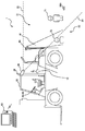
- FIG. 1 is a diagram showing an attachment example of the image processing system according to the first embodiment.
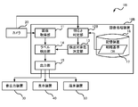
- FIG. 2 is a block diagram showing the configuration of the image processing system according to the first embodiment.
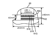
- FIG. 3A is a side view of a helmet worn by a person.
- FIG. 3B is a view of a helmet worn by a person viewed from above.
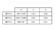
- FIG. 4 is a diagram showing an expression in the Munsell color system (JIS Z8721) of each color label.
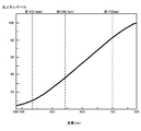
- FIG. 5 is a diagram showing the spectral reflectance of each color label.
- FIG. 6 is a diagram showing a spectral distribution of sunlight.
- FIG. 7: is a figure which shows typically the label image
- FIG. 7 is a figure which shows typically the label image
- FIG. 8 is a figure which shows the spectral distribution of the light of an incandescent lamp.
- FIG. 9 is a figure which shows typically the label image
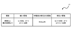
- FIG. 10 is a diagram showing an example of the brightness/darkness reference DB.
- FIG. 11A is a diagram showing an example of a green region and a red region on an image.
- FIG. 11B is a diagram showing an example of a green region and a red region on the image.
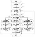
- FIG. 12 is a flowchart showing a procedure of processing executed by the image processing apparatus according to the first embodiment.
- FIG. 13 is a diagram showing an example of a label attached to a helmet.
- FIG. 14 is a flowchart showing a procedure of processing executed by the image processing apparatus according to the second embodiment.
- FIG. 15 is a flowchart showing a procedure of processing executed by the image processing apparatus according to the modified example of the second embodiment.
- FIG. 16 is a block diagram showing the configuration of the image processing system according to the third embodiment.
- FIG. 17 is a diagram showing an example of the brightness/darkness reference DB.
- FIG. 18 is a block diagram showing the configuration of the image processing system according to the fourth embodiment.
- FIG. 19 is a diagram showing an example of the brightness/darkness reference DB.
- FIG. 20 is a diagram showing an example of the brightness/darkness reference DB.
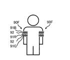
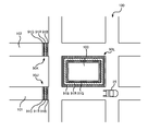
- FIG. 21 is a diagram of a person viewed from the front.
- FIG. 22 is an external view of a cardboard box.
- FIG. 23 is a diagram schematically showing a road on which a forklift truck travels.
- the color of the mark is easily influenced by the illumination, and even if the mark has the same color, the mark may be captured by the camera as a mark of a different color when the illumination is different. Specifically, when the red mark is photographed under sunlight like outdoors in the daytime, the red mark may appear yellow. Further, when the blue mark is photographed under the light of an incandescent lamp indoors, the blue mark may appear black. If the mark is photographed as an area having a color different from the original color, the two-dimensional code may be erroneously detected or the information may be erroneously recognized.
- the present disclosure has been made in view of such circumstances, and an image processing device, a computer program, and an image processing system capable of detecting a label including a predetermined number or more of color regions without being affected by illumination.
- the purpose is to provide.
- a label including a predetermined number or more of color regions can be detected without being affected by illumination.
- An image processing device is an image processing device that detects a label attached to a detection target, and an image acquisition unit that acquires a color image captured by a camera, and the camera. Based on the determination result of the brightness determination unit and the brightness determination unit, one or more colors among colors attached to the label including a predetermined number of color regions or more.
- the detection target color determination unit that determines the detection target color, and the label is detected by extracting the region of the detection target color determined by the detection target color determination unit from the image acquired by the image acquisition unit.
- one or more detection target colors are determined from the colors of the label including the predetermined number or more of color areas, based on the brightness of the imaging range of the camera.
- the label includes a retroreflective material in the area.
- ⁇ Retroreflective material has the property that the incident angle of light is equal to the outgoing angle. Therefore, even if the label is inclined in either direction, the camera can receive the reflected light of the light by irradiating the label with light along the optical axis direction of the camera. As a result, the label can be detected with high accuracy even at night.
- the brightness determination unit is configured such that the image acquired by the image acquisition unit, imaging parameter information regarding brightness adjustment acquired from the camera, and illuminance at a position included in an imaging range of the camera.
- the brightness may be determined based on at least one piece of illuminance information acquired from an illuminance sensor that measures.
- the detection target color determination unit determines, as the detection target color, an intermediate wavelength color that is at least a color other than the color having the longest wavelength and the color having the shortest wavelength among the predetermined number of colors or more. You may.
- the color with a long wavelength is taken as a color different from the original color
- the color with a short wavelength is taken as a color different from the original color. To be done. Therefore, at least the intermediate wavelength colors other than these colors are not easily affected by the illumination. Therefore, according to this configuration, the label can be detected without being affected by the illumination.
- the label detection unit may extract the regions of the detection target color in order from the region of the intermediate wavelength color.
- the label may include a red area, a blue area, and a green area.
- the three primary colors of light, red, blue, and green, are colors with wavelengths that are appropriately separated. For this reason, even if one of the areas of one color is photographed as a color area different from the original color due to the influence of the illumination, the other two colors are not affected by the illumination and the Taken as a color area. Therefore, by using the other two colors as the detection target colors, the label can be detected without being affected by the illumination.
- the above image processing apparatus may further include an output unit that outputs information according to the detection result of the label detection unit.
- a computer program is a computer program for causing a computer to function as an image processing device that detects a label attached to a detection target, and the computer is imaged by a camera.
- An image acquisition unit that acquires a color image, a brightness determination unit that determines the brightness of the imaging range of the camera, and a predetermined number or more of color regions based on the determination result of the brightness determination unit
- the detection target color determination unit that determines one or more detection target colors from the colors attached to the label, and the detection that the detection target color determination unit determines from the image acquired by the image acquisition unit By extracting the region of the target color, it functions as a label detection unit that detects the label.
- the computer can be realized as the image processing device described above. Therefore, the same operation and effect as those of the image processing apparatus described above can be obtained.
- An image processing system includes a label that is attached to a detection target and includes a predetermined number or more of color regions, a camera that captures a color image, and the image processing device described above. Equipped with.
- This configuration includes the image processing device described above. Therefore, the same operation and effect as those of the image processing apparatus described above can be obtained.
- FIG. 1 is a diagram showing an attachment example of the image processing system according to the first embodiment.
- FIG. 2 is a block diagram showing the configuration of the image processing system according to the first embodiment.
- the following describes an image processing system in which a camera and an image processing device are installed on a forklift, but the location where the camera and the image processing device are installed is not limited to the forklift. For example, these may be attached to the automobile, or when the camera is used for monitoring a predetermined area, the camera may be installed at a place where the area can be imaged.
- the image processing system 1 is a system for monitoring the periphery of the forklift 25, and includes a camera 20, an illuminance sensor 26, an image processing device 10, a sound output device 30, a display device 40, and a terminal device 50.
- a camera 20 an illuminance sensor 26
- an image processing device 10 an image processing device 10
- a sound output device 30 a display device 40
- a terminal device 50 a terminal device 50.
- the camera 20 is attached, for example, at a position where the rear of the forklift 25 can be imaged (for example, the rear end position of the head guard of the forklift 25) and captures a color image of the rear of the forklift 25.
- the camera lens of the camera 20 is, for example, an ultra wide-angle lens having an angle of view of 120° or more.
- the forklift 25 be provided with a light source such as a headlight so that the camera 20 can shoot at night. Further, it is desirable that the light source emits light in the optical axis direction of the camera 20.
- a blind spot region 22 that deviates from the imaging region 21 of the forklift 25.
- the boundary 23 between the imaging area 21 and the blind spot area 22 is indicated by a broken line.
- a mirror 60 is installed in the image pickup area 21 of the forklift 25. That is, by disposing the mirror 60 so that the image pickup area 61 covers the blind spot area 22 when the camera 20 picks up the image through the mirror 60, the camera 20 can pick up the person 72 existing in the blind spot area 22. it can.
- another camera different from the camera 20 may be arranged on the forklift 25 in order to image the blind spot area 22.
- Illuminance sensor 26 is a sensor that measures the illuminance by converting the light incident on the light receiving element into an electric current.
- the illuminance sensor 26 is arranged, for example, on the ceiling portion of the forklift 25 and measures the illuminance at a position included in the imaging range of the camera 20.
- the illuminance sensor 26 is preferably provided near the camera 20 or in the imaging area 21. Further, it is desirable that the illuminance sensor 26 is attached at a position where the sensor surface of the illuminance sensor 26 is perpendicular to the optical axis direction so that the illuminance of the camera 20 in the optical axis direction can be measured.
- the illuminance sensor 26 does not necessarily have to be installed on the forklift 25.
- the illuminance sensor 26A may be installed in advance within the travelable range of the forklift 25. That is, the illuminance sensor 26A may be installed on the traveling route of the forklift 25 or in the vicinity of the traveling route.
- the illuminance sensor 26A is a sensor that measures the illuminance of the surroundings, like the illuminance sensor 26.
- the measurement range of the illuminance by the illuminance sensor 26 or 26A is preferably included in the shooting range of the camera 20, but the measurement range and the shooting range may be slightly different as long as they are about several meters. This is because it is unlikely that the illuminance will change abruptly due to a slight positional shift, and it is considered that such a shift will not affect the result of image processing.
- the image processing device 10 is a computer installed in the forklift 25.
- the image processing device 10 is connected to the camera 20 and detects the persons 71 and 72 from the images of the imaging regions 21 and 61 captured by the camera 20.
- the persons 71 and 72 are labeled with a predetermined number of color areas arranged in a predetermined positional relationship.
- the predetermined number is not limited to 3 and may be any other number as long as it is a natural number of 1 or more. That is, it is sufficient that the label has at least one predetermined color region.
- the label preferably includes a retroreflective material in the color area.
- the retroreflective material is, for example, glass beads arranged on the surface of the label, and has a property of reflecting the light from the light source in the glass beads and returning the reflected light to the light source direction.
- FIG. 3A is a side view of a helmet worn by a person, and FIG. 3B is a top view of the helmet.
- a label 90A is attached to the helmet 80.
- the label 90A includes a blue label 91B, a red label 91R and a green label 91G which are arranged in parallel.
- the label 90A can have a width of about 60 mm and a length of about 180 to 250 mm.
- a gap area 92 is provided between the blue label 91B and the red label 91R and between the red label 91R and the green label 91G.
- the gap area 92 is, for example, a black area and has a width of 2 to 3 mm.
- a label 90A similar to the label 90A shown in FIG. 3A is also attached above the helmet 80.
- the label 90A is also attached to the opposite side surface of the helmet 80 and to the front and back. 3A, only the label 90A on the left side surface of the helmet 80 is shown for the sake of illustration. In this way, by attaching the label 90A to every place, it is possible to cause the camera 20 to capture an image of any label 90A regardless of the posture of the person (upright, crouching, etc.). it can.
- the label 90A is composed of a red label 91R, a green label 91G, and a blue label 91B, which are labels of the three primary colors of light.
- FIG. 4 is a diagram showing an expression in the Munsell color system (JIS (Japanese Industrial Standards) Z8721) of each color label.
- H, V, and C respectively indicate the hue, lightness, and saturation in the Munsell color system. That is, the color of the red label 91R includes the Munsell color system hue (H) in the range of 10P to 7.5YR, the lightness (V) of 3 or more, and the saturation (C) of 2 or more. ..
- the color of the green label 91G includes the Munsell color system hue (H) in the range of 2.5 GY to 2.5 BG, the lightness (V) of 3 or more, and the saturation (C) of 2 or more. ..
- the color of the blue label 91B includes the Munsell color system hue (H) in the range of 5BG to 5P, the lightness (V) of 1 or more, and the saturation (C) of 1 or more.
- the label 90A is not limited to the label composed of the three primary colors of light, and may be composed of the label of other colors.
- FIG. 5 is a diagram showing the spectral reflectance of each color label.
- the horizontal axis represents wavelength (nm) and the vertical axis represents spectral reflectance (%).
- the red color indicated by the red label 91R has a spectral reflectance peak near a wavelength of 700 nm.
- the green color indicated by the green label 91G has a spectral reflectance peak near a wavelength of 546.1 nm.
- the blue color indicated by the blue label 91B has a spectral reflectance peak near the wavelength of 435.8 nm.
- the peak of the spectral reflectance of each color is not limited to the above value.
- red may have a spectral reflectance peak at a wavelength of 700 ⁇ 30 nm.
- Green may have a peak of spectral reflectance at a wavelength of 546.1 ⁇ 30 nm.
- Blue may have a peak of spectral reflectance at a wavelength of 435.8 ⁇ 30 nm.
- the blue label 91B, the red label 91R, and the green label 91G are made of fluorescent tape or that these labels are coated with fluorescent paint.
- the label can be easily recognized even in an environment where the illuminance is low, such as at night or in cloudy weather. Further, the label can be recognized without using a special camera such as an infrared camera.
- the image processing apparatus 10 detects a person by detecting the label 90A from the image captured by the camera 20.
- the detailed configuration of the image processing apparatus 10 will be described later.
- the sound output device 30 is installed, for example, near the driver's seat of the forklift 25 and includes a speaker.
- the sound output device 30 is connected to the image processing device 10 and outputs a notification sound such as a message sound or an alarm sound that notifies the driver that the image processing device 10 has detected the person 71 or the person 72.
- the display device 40 is installed, for example, at a position where the driver of the forklift 25 can visually recognize, and is configured to include a liquid crystal display and the like.
- the display device 40 is connected to the image processing device 10 and displays an image informing that the image processing device 10 has detected the person 71 or the person 72.
- the terminal device 50 is, for example, a computer installed in a place apart from the forklift 25, such as a management room that manages the forklift 25.
- the terminal device 50 is connected to the image processing device 10 and outputs an image or a sound notifying that the image processing device 10 has detected the person 71 or the person 72, or detects that the person 71 or the person 72 has been detected together with time information. It is recorded as log information.
- the terminal device 50 and the image processing device 10 are connected by a mobile phone line according to a communication standard such as 4G or 5G, or a wireless LAN (Local Area Network) such as Wi-Fi (registered trademark). May be.
- the terminal device 50 may be a smartphone or the like carried by the person 71 or 72. Thereby, the terminal device 50 can notify the person 71 or 72 that the person 71 or 72 itself has been detected by the image processing apparatus 10, that is, that the forklift 25 exists near the person 71 or 72. it can.
- the functions of the image processing device 10, the camera 20, the sound output device 30, and the display device 40 may be provided in a smartphone, a computer with a camera, or the like.
- the smartphone processes the image captured by the smartphone and detects the persons 71 and 72.
- the smartphone notifies the detection result by sound or image.
- another tablet device or the like may be installed at a position visible to the driver, and the tablet device may display the image transmitted from the smartphone.
- the tablet device and the smartphone may be wirelessly connected according to a wireless communication standard such as Wi-Fi (registered trademark), Bluetooth (registered trademark), Zigbee (registered trademark).
- FIG. 6 is a diagram showing the spectral distribution of sunlight.
- the horizontal axis represents wavelength and the vertical axis represents radiant energy.
- the red light component is smaller than the green and blue light components. For this reason, when the camera 20 photographs the red region outdoors using the sun as the light source, the light of the red component received by the camera 20 becomes relatively weak. Therefore, the red area may appear as a yellow area on the image.
- FIG. 7 is a figure which shows typically the label image
- the label 90A shown in FIG. 7 is the same as the label 90A shown in FIG. 3A.
- the intensity of the red component light is weak due to the effect of sunlight. Therefore, the red label 91R appears as a yellow label on the image.
- FIG. 8 is a diagram showing a spectral distribution of light from an incandescent lamp.
- the horizontal axis represents wavelength and the vertical axis represents specific energy.
- the specific energy is a relative intensity when the maximum value of the emission intensity in the measured wavelength range is 100%.
- the blue component is less than the red and green components. For this reason, when the camera 20 shoots a blue region indoors using an incandescent lamp as a light source, the blue component light received by the camera 20 becomes relatively weak. Therefore, the blue area may appear as a black area on the image.
- FIG. 9 is a figure which shows typically the label image
- the label 90A shown in FIG. 9 is the same as the label 90A shown in FIG. 3A.
- the intensity of the blue component light is weak due to the effect of the light from the incandescent lamp. Therefore, the blue label 91B appears as a black label on the image.
- the lighting used in a dark environment is not limited to incandescent light bulbs, and may be light bulbs of other colors, fluorescent lights or LED (Light Emitting Diode) lighting.
- an image processing device 10 that can detect the label 90A without being affected by illumination will be described below.
- the image processing device 10 is a general computer including a CPU (Central Processing Unit), a RAM (Random Access Memory), a ROM (Read Only Memory), an HDD (Hard Disk Drive), a communication I/F (interface), a timer, and the like. It is composed of The image processing apparatus 10 has an image acquisition unit 11, a brightness determination unit 12, a detection target color determination unit 13 as a functional configuration realized by executing a computer program read from a HDD or a ROM into a RAM. The label detection unit 14 and the output unit 15 are provided.
- the image processing apparatus 10 also includes a storage device 16.
- the image acquisition unit 11 acquires a color image captured by the camera 20 via the communication I/F. That is, an image obtained by the camera 20 capturing the image capturing areas 21 and 61 shown in FIG. 1 is acquired.
- the brightness determination unit 12 determines the brightness of the imaging range of the camera 20.
- the brightness determination unit 12 refers to the brightness/darkness reference DB (database) stored in the storage device 16 described later on the basis of the illuminance information of the imaging range of the camera 20 measured by the illuminance sensor 26 and refers to the camera 20. It is determined whether the imaging range of is a bright environment, a dark environment, or an environment of medium brightness.
- the brightness determination unit 12 may directly receive the illuminance information from the illuminance sensor 26A by wireless communication when acquiring the illuminance information from the illuminance sensor 26A installed other than the forklift 25, or the terminal device 50.
- the illuminance information may be received from the illuminance sensor 26A via the.
- the brightness determination unit 12 specifies the illuminance sensor 26A included in the imaging range of the camera 20 from the position of the forklift 25 and the camera parameters (optical axis direction, zoom magnification, etc.) of the camera 20, and specifies the specified illuminance.
- the illuminance information is acquired from the sensor 26A.
- the brightness determination unit 12 compares the position of the illuminance sensor 26A indicated by the acquired position information with the position of the forklift 25 when the position information can be acquired together with the illuminance information from the illuminance sensor 26A.
- the illuminance sensor 26A included in the imaging range of the camera 20 may be specified.
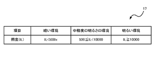
- FIG. 10 is a diagram showing an example of the brightness/darkness reference DB 17.
- the brightness/darkness reference DB 17 indicates a reference for determining whether the environment having the illuminance is a bright environment, a dark environment, or a medium brightness environment based on the illuminance (IL).
- IL illuminance
- the environment where the illuminance is IL ⁇ 500 lx is a dark environment.
- the environment where the illuminance is 500 ⁇ IL ⁇ 10000 is a medium brightness environment.
- the environment in which the illuminance is IL ⁇ 10000 is a bright environment.
- the brightness determination unit 12 determines that the imaging range of the camera 20 is a dark environment if the illuminance IL measured by the illuminance sensor 26 is IL ⁇ 500 lx. If the illuminance IL measured by the illuminance sensor 26 is 500 ⁇ IL ⁇ 10000, the brightness determination unit 12 determines that the image capturing range of the camera 20 is an environment of medium brightness. Furthermore, if the illuminance IL measured by the illuminance sensor 26 is IL ⁇ 10000, the brightness determination unit 12 determines that the imaging range of the camera 20 is a bright environment. It is needless to say that the numerical values indicated by the brightness/darkness reference DB 17 are examples, and other numerical values may be used. The same applies to subsequent figures.
- the detection target color determination unit 13 determines one or more detection target colors from the colors attached to the label 90A based on the determination result of the brightness determination unit 12. Hereinafter, it is assumed that the detection target color determination unit 13 determines two or more detection target colors from the three colors attached to the label 90A. That is, the detection target color determination unit 13 determines, as a detection target color, a color excluding a color whose appearance changes depending on the illumination environment.
- the detection target color determination unit 13 determines two colors, green and blue, excluding red, as detection target colors.
- the blue area may appear as a black area in the image. Therefore, when the brightness determination unit 12 determines that the environment is dark, the detection target color determination unit 13 determines two colors, red and green, excluding blue, as detection target colors.
- the dark environment referred to here indicates the environment under the light of an incandescent light bulb. Therefore, under other artificial light sources such as fluorescent lamps and LED lighting, the color in which the appearance changes is not always blue. Therefore, when the artificial light source is other than an incandescent light bulb, the detection target color determination unit 13 determines a color excluding a color whose appearance changes according to the type of the artificial light source as the detection target color.
- the detection target color determination unit 13 determines three colors of red, green, and blue as the detection target colors when the brightness determination unit 12 determines that the environment has medium brightness.
- the label detection unit 14 detects the label 90A by extracting the area of the detection target color determined by the detection target color determination unit 13 from the image acquired by the image acquisition unit 11.
- the label detection unit 14 extracts the region of the detection target color based on the pixel value in the color space of each pixel forming the image acquired by the image acquisition unit 11 and a predetermined threshold value.
- the HSV color space is assumed as the color space.
- hue (H), saturation (S), and lightness (V) are assumed as pixel values in the HSV color space.
- the label detection unit 14 converts the pixel value in the RGB color space into the pixel value in the HSV color space, and then Region extraction processing is performed.
- the conversion from the pixel value of the RGB color space to the pixel value of the HSV color space is executed according to the following Expressions 1 to 3, for example.
- R, G, and B represent the red component, green component, and blue component of the pixel before conversion, respectively.
- MAX represents the maximum value of the red component, green component, and blue component of the pixel before conversion.
- MIN represents the minimum value of the red component, green component, and blue component of the pixel before conversion.
- the label detection unit 14 for example, 95 and 145 are set as the threshold value of the green hue (H), 70 and 100 are set as the threshold value of the green saturation (S), and the green lightness (V) is set. It is assumed that 70 and 100 are set as the threshold values.
- the label detection unit 14 has a hue (H) of a pixel of 95 or more and 145 or less, a saturation (S) of 70 or more and 100 or less, and a lightness (V) of 70.
- H hue
- S saturation
- V lightness
- the label detection unit 14 has red (H), saturation (S) and lightness (V) thresholds and blue (H), saturation (S) and lightness (V) thresholds. It is assumed that and are set.
- red is the detection target color
- the label detection unit 14 extracts red pixels from the image using the threshold values of the hue (H), saturation (S), and lightness (V) of red.
- blue is the detection target color
- the label detection unit 14 extracts blue pixels from the image using the threshold values of blue hue (H), saturation (S), and lightness (V).
- the label detection unit 14 performs labeling processing on green pixels, red pixels, or blue pixels, which are pixels of the color to be detected, and sets pixels having the same label (code) by the labeling processing as one area. , Green area, red area or blue area is extracted.
- the label detection unit 14 may remove the noise area by performing expansion/contraction processing or area size filtering processing on each of the extracted green area, red area, or blue area.
- the label detection unit 14 determines that the image acquired by the image acquisition unit 11 includes the detection target color region when the extracted detection target color regions have a predetermined positional relationship. For example, when the detection target colors are red, green, and blue, the label detection unit 14 determines that a red area exists within a predetermined distance range from the center position of the green area on the image and the center position of the red area is predetermined. When the blue area exists within the distance range, it is determined that the image includes the green area, the red area, and the blue area. When the label detection unit 14 determines that the image includes the region of the detection target color, it is determined that the label 90A is detected in the image. Thereby, the label detection unit 14 can determine that a person is present around the forklift 25.
- the label detection unit 14 may change the threshold values of the hue (H), saturation (S), and lightness (V) of each color according to the determination result of the brightness determination unit 12. By changing the threshold value according to the brightness of the imaging range of the camera 20, the label detection unit 14 can more accurately extract the area. For example, the label detection unit 14 may change each threshold so that the hue (H), the saturation (S), and the brightness (V) of each color become larger as the imaging range becomes brighter. Specifically, the label detection unit 14 refers to the table information indicating the correspondence relationship between the brightness of the imaging range and the threshold values of the hue (H), the saturation (S), and the brightness (V) of each color, Each threshold may be changed.
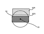
- FIG. 11A and 11B are diagrams showing an example of a green region and a red region on the image. As shown in FIG. 11A, if the red region 82R is included in a predetermined distance range 84 indicated by a circle centered on the center position 83 of the green region 82G, the center position 83 of the green region 82G is displayed on the image. It is determined that the red area 82R exists within the predetermined distance range 84.
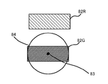
- the red region 82R is not included in the predetermined distance range 84 indicated by a circle centered on the center position 83 of the green region 82G, the center position of the green region 82G on the image. It is determined that the red region 82R does not exist within the predetermined distance range 84 from 83.
- the diameter of the circle in the predetermined distance range 84 may be the length of the longest side of the green region 82G, for example.
- the length of the longest side of the circumscribed rectangle of the green region 82G may be the diameter of the circle of the predetermined distance range 84.
- the diameter may be a value other than these.
- the label detection unit 14 performs similar processing to determine whether the extracted detection target color regions have a predetermined positional relationship. To determine.
- the output unit 15 outputs information according to the detection result of the label detection unit 14. For example, when the label detection unit 14 detects the label 90A, the output unit 15 notifies the sound output device 30 of transmitting a predetermined sound signal to the sound output device 30 via the communication I/F. Output sound. This notifies the driver that there is a person around the forklift 25.
- the output unit 15 detects a person on the display device 40 by transmitting a predetermined image signal to the display device 40 via the communication I/F. Display an image to inform you. This notifies the driver that there is a person around the forklift 25.
- the output unit 15 transmits information indicating that a person is detected to the terminal device 50 via the communication I/F, so that the terminal device
- the control unit 50 causes the sound and image to be output and the log information to be recorded.
- the output unit 15 may transmit information on the detection time.
- the storage device 16 is a storage device for storing various information including the brightness/darkness reference DB 17, and is configured by a magnetic disk, a semiconductor memory, or the like.
- FIG. 12 is a flowchart showing a procedure of processing executed by the image processing apparatus 10 according to the first embodiment.
- the image acquisition unit 11 acquires an image captured by the camera 20 (S1).
- the label detection unit 14 extracts a green area from the image acquired by the image acquisition unit 11 (S2). Since the green region can be extracted without being affected by the illumination environment, green is an essential detection target color. Therefore, the extraction process of the green region is executed without performing the detection target color determination process (steps S6, S9, and S12 described later) by the detection target color determination unit 13.
- the brightness determination unit 12 refers to the brightness/darkness reference DB 17 based on the illuminance of the imaging range of the camera 20 measured by the illuminance sensor 26, and the brightness of the camera 20 is determined. Brightness determination processing is performed to determine whether the imaging range is a bright environment, a dark environment, or an environment of medium brightness (S4).
- step S4 when it is determined that the imaging range of the camera 20 is a bright environment (bright in S5), the detection target color determination unit 13 sets green and blue as the detection target colors. Determine (S6)
- the label detection unit 14 extracts a blue area that is an unextracted detection target color area (S7).
- the label detection unit 14 determines whether a blue area having a predetermined positional relationship with the green area is extracted from the image (S8).
- the label detection unit 14 detects the green area and the blue area as the label 90A, and the output unit 15 detects the detection result of the label 90A.
- Output For example, the output unit 15 causes the sound output device 30 to output a notification sound by transmitting a predetermined sound signal to the sound output device 30.
- the detection target color determination unit 13 sets red and green as the detection target colors. It is determined (S9).
- the label detection unit 14 extracts a red area which is an unextracted detection target color area (S10).
- the label detection unit 14 determines whether or not a red area having a predetermined positional relationship with the green area is extracted from the image (S11).
- the label detection unit 14 detects the red area and the green area as the label 90A, and the output unit 15 detects the detection result of the label 90A. Output (S15).
- the detection target color determination unit 13 determines that the red, Green and blue are determined as detection target colors (S12).
- the label detection unit 14 extracts a red area and a blue area, which are unextracted detection target color areas (S13).
- the label detection unit 14 determines whether or not a red area and a blue area having a predetermined positional relationship with the green area are extracted from the image (S14).
- the label detection unit 14 detects the red area, the green area, and the blue area as the label 90A, and the output unit 15 The detection result of the label 90A is output (S15).
- step S14 if at least one of the red area and the blue area has a predetermined positional relationship with the green area, it may be determined that the image includes the label 90A.
- the label detection result output process may be performed even when the label 90A is not detected. That is, the output unit 15 may cause the sound output device 30 to output a notification sound indicating that the label 90A has not been detected, or may cause the display device 40 to display an image indicating that the label 90A has not been detected. May be. Further, the output unit 15 may transmit information indicating that the label 90A has not been detected to the terminal device 50.
- the image processing apparatus 10 repeatedly executes the processing shown in FIG. 12 at a predetermined cycle (for example, every 100 msec). Thereby, the label 90A can be detected in real time.
- the detection target color determining unit 13 sets the brightness of the image capturing range of the camera 20 to the brightness of the image capturing range of the label 90A that includes a predetermined number or more of color regions. Based on this, one or more colors to be detected are determined. Specifically, the detection target color determination unit 13 determines two or more detection target colors from the colors of the label 90A including the areas of three or more colors, based on the brightness of the imaging range of the camera 20. .. As a result, it is possible to determine the detection target color by excluding the color whose color appearance changes depending on the brightness. Therefore, the label detection unit 14 can detect the label without being affected by the illumination by extracting the region of the detection target color.
- the label 90A includes a retroreflective material in the color area.
- the retroreflective material has a property that the incident angle of light and the outgoing angle of light become equal. Therefore, even if the label 90A is inclined in any direction, the camera 20 receives the reflected light of the label 90A by irradiating the label 90A with light along the optical axis direction of the camera 20. can do. Accordingly, the label detection unit 14 can detect the label 90A with high accuracy even at night.
- the brightness determination unit 12 can determine the brightness of the imaging range of the camera 20 based on the illuminance of the imaging range of the camera 20 measured by the illuminance sensor 26. Therefore, the brightness of the imaging range of the camera 20 can be easily determined.
- the detection target color determination unit 13 indispensably detects green of an intermediate wavelength color, which is a color other than red having the longest wavelength and blue having the shortest wavelength, among red, green, and blue, regardless of the illumination environment. Determined as the target color. Since green is a color that is not easily affected by illumination, the label detection unit 14 can detect the label 90A without being affected by illumination.
- the label detection unit 14 performs the area extraction processing by giving priority to the green area of the intermediate wavelength color which is an essential detection target color (S2 in FIG. 12). As a result, when the green region cannot be extracted, the label detection unit 14 does not need to extract the red region or the blue region, which is another detection target color, and the processing time can be shortened.
- the label 90A is composed of a red label 91R, a green label 91G and a blue label 91B.
- the three primary colors of light, red, blue and green, are colors whose wavelengths are appropriately separated. For this reason, even if one of the areas (red or blue) is photographed as a color area different from the original color due to the influence of illumination, the other two colors including the intermediate wavelength color green are The image is captured as a color region of the original color without being affected by lighting. Therefore, by using the other two colors as the detection target colors, the label can be detected without being affected by the illumination.
- the output unit 15 When the label detection unit 14 detects the label 90A, the output unit 15 causes the sound output device 30 to output a sound indicating that the label 90A has been detected, a sound such as an alarm sound, or a detection result of the label 90A. It is possible to display an image showing “” on the display device 40.
- the output unit 15 can also send information indicating the detection result of the label 90A to the terminal device 50. This allows the user to be notified of the detection result of the label 90A.
- the label is composed of the blue label 91B, the red label 91R and the green label 91G, but the color of the label is not limited to these.
- the second embodiment an example using a label composed of four color labels will be described.
- FIG. 13 is a diagram showing an example of a label attached to a helmet.
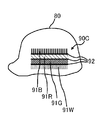
- a label 90C is attached to the helmet 80.
- the label 90C is composed of a blue label 91B, a red label 91R, a green label 91G and a white label 91W which are arranged in parallel. Further, gap regions 92 are provided between the blue label 91B and the red label 91R, between the red label 91R and the green label 91G, and between the green label 91G and the white label 91W.
- White is an achromatic color with zero saturation and contains various wavelengths. Therefore, the white label 91W is a label that can be detected without being affected by the brightness.
- the label detection unit 14 extracts a white pixel in an image
- the saturation (S) and the brightness (V) of each pixel are compared with their respective thresholds.
- the hue (H) is not compared with the threshold value.
- the label detection unit 14 extracts from the image the pixels having the saturation (S) and the brightness (V) that exceed the saturation threshold and the brightness threshold of white, respectively, as white pixels, and extracts the extracted white pixels.
- a white area is extracted by performing labeling processing.
- the configuration of the image processing apparatus according to the second embodiment is similar to that shown in FIG. However, the processes of the detection target color determination unit 13 and the label detection unit 14 are partially different. Hereinafter, the processing different from that of the first embodiment will be described with reference to the flowchart shown in FIG.
- FIG. 14 is a flowchart showing a procedure of processing executed by the image processing apparatus 10 according to the second embodiment.
- the image processing device 10 executes the processes of steps S1 to S4.
- the processing of steps S1 to S4 is the same as that shown in FIG.
- the detection target color determination unit 13 detects green, blue, and white as detection targets. The color is determined (S6A).
- the label detection unit 14 extracts a blue area and a white area, which are unextracted detection target color areas (S7A).
- the label detecting unit 14 determines whether or not a blue area and a white area having a predetermined positional relationship with the green area are extracted from the image (S8A).
- the label detection unit 14 detects the green region, the blue region, and the white region as the label 90C, and the output unit 15 The detection result of the label 90C is output (S15).
- the label detection unit 14 extracts a red area and a white area which are unextracted detection target color areas (S10A).
- the label detection unit 14 determines whether or not a red area and a white area having a predetermined positional relationship with the green area are extracted from the image (S11A).
- the label detection unit 14 detects the red area, the green area, and the white area as the label 90C, and the output unit 15 The detection result of the label 90C is output (S15).
- the detection target color determination unit 13 determines that the red, Green, blue and white are determined as detection target colors (S12A).
- the label detection unit 14 extracts a red area, a blue area, and a white area, which are unextracted detection target color areas (S13A).
- the label detection unit 14 determines whether a red area, a blue area, and a white area having a predetermined positional relationship with the green area are extracted from the image (S14A).
- the label detection unit 14 detects the red area, the green area, the blue area, and the white area as the label 90C.
- the output unit 15 outputs the detection result of the label 90C (S15).
- the image processing apparatus 10 repeatedly executes the processing shown in FIG. 14 at a predetermined cycle (for example, 100 msec intervals). Thereby, the label 90C can be detected in real time.
- a predetermined cycle for example, 100 msec intervals.
- label detection can be performed using color labels of more colors than in the first embodiment. Therefore, the label can be detected without being affected by the illumination.
- the color of the color label included in the label is not limited to the above, and for example, a black label may be used instead of the white label 91W.
- the label is composed of four color labels, as in the second embodiment.
- the procedure of the processing executed by the image processing apparatus 10 is different from that in the second embodiment.
- FIG. 15 is a flowchart showing a procedure of processing executed by the image processing apparatus 10 according to the modified example of the second embodiment.
- the image processing device 10 executes the processes of steps S1 to S3.
- the processing of steps S1 to S3 is the same as that shown in FIG.
- the label detection unit 14 extracts the white area from the image acquired by the image acquisition unit 11 (S21). Since the white area can be extracted without being affected by the illumination environment, white is an essential detection target color. Therefore, the white region extraction process is executed without performing the detection target color determination process (steps S6A, S9A, and S12A described later) by the detection target color determination unit 13.
- the detection target color determination unit 13 detects green, blue, and white as detection targets. The color is determined (S6A).
- the label detection unit 14 extracts a blue area that is an unextracted detection target color area (S7).
- the label detecting unit 14 determines whether a blue area having a predetermined positional relationship with the green area and the white area is extracted from the image (S8B).
- the label detection unit 14 detects the green area, the blue area, and the white area as the label 90C, and the output unit 15 outputs the label 90C.
- the detection result is output (S15).
- step S4 when it is determined that the imaging range of the camera 20 is a dark environment (dark in S5), the detection target color determination unit 13 detects red, green, and white as detection targets. The color is determined (S9A).
- the label detection unit 14 determines whether or not a red area having a predetermined positional relationship with the green area and the white area is extracted from the image (S11B).
- the label detection unit 14 detects the red area, the green area, and the white area as the label 90C, and the output unit 15 outputs the label 90C.
- the detection result is output (S15).
- the detection target color determination unit 13 determines that the red, Green, blue and white are determined as detection target colors (S12A).
- the label detection unit 14 extracts a red area and a blue area, which are unextracted detection target color areas (S13A).
- the label detection unit 14 determines whether or not a red area and a blue area having a predetermined positional relationship with the green area and the white area are extracted from the image (S14B).
- the label detection unit 14 detects the red area, the green area, the blue area, and the white area as the label 90C, and the output unit 15 outputs the detection result of the label 90C (S15).
- the image processing apparatus 10 repeatedly executes the processing shown in FIG. 15 at a predetermined cycle (for example, 100 msec intervals). Thereby, the label 90C can be detected in real time.
- a predetermined cycle for example, 100 msec intervals.
- the brightness of the imaging range of the camera 20 is determined based on the measurement result of the illuminance sensor.
- an example of performing brightness determination without using an illuminance sensor will be described.
- FIG. 16 is a block diagram showing the configuration of the image processing system according to the third embodiment.
- An image processing system 1A shown in FIG. 16 includes an image processing apparatus 10A instead of the image processing apparatus 10 in the configuration of the image processing system 1 shown in FIG.
- the image processing device 10A is configured by a computer like the image processing device 10.
- the image processing apparatus 10A includes a brightness determination unit 12A instead of the brightness determination unit 12 as a functional configuration.
- the brightness determination unit 12A is connected to the image acquisition unit 11 and determines the brightness of the imaging range of the camera 20 based on the image acquired by the image acquisition unit 11. That is, the brightness determination unit 12A calculates the average of the brightness of the pixels included in the image acquired by the image acquisition unit 11, and refers to the brightness/darkness reference DB 17 stored in the storage device 16 based on the calculated brightness average. And determine the brightness.
- FIG. 17 is a diagram showing an example of the light/dark reference DB 17.
- the brightness/darkness reference DB 17 shows a reference for determining whether the environment having the brightness average is a bright environment, a dark environment, or an environment of medium brightness based on the brightness average (M).
- M brightness average
- the environment in which the average brightness is M ⁇ 50 is a dark environment.
- the environment where the average luminance is 50 ⁇ M ⁇ 130 is a medium brightness environment.
- the environment in which the average brightness is M ⁇ 130 is a bright environment. Note that the luminance has 256 gradations as an example.
- the brightness determination unit 12 determines that the imaging range of the camera 20 is a dark environment. If the average brightness M is 50 ⁇ M ⁇ 130, the brightness determination unit 12 determines that the imaging range of the camera 20 is an environment of medium brightness. Furthermore, if the average brightness M is M ⁇ 130, the brightness determination unit 12 determines that the imaging range of the camera 20 is a bright environment.
- the procedure of the processing executed by the image processing apparatus 10 is the same as in the first or second embodiment.
- the brightness can be determined without using the illuminance sensor 26. Therefore, the brightness can be determined at low cost.
- the forklift 25 when the forklift 25 is located indoors and the camera 20 is photographing a bright environment outdoors, if the brightness determination is performed using the illuminance sensor 26, it is determined to be a dark environment, and the photographing is performed. The result may differ from the target environment. However, when the brightness is determined by using the average luminance of the images, it is determined that the environment is bright as in the environment in which the camera 20 is an imaging target. Therefore, the label can be detected more accurately.
- FIG. 18 is a block diagram showing the configuration of the image processing system according to the fourth embodiment.
- An image processing system 1B shown in FIG. 18 includes an image processing device 10B instead of the image processing device 10 in the configuration of the image processing system 1 shown in FIG.
- the image processing device 10B is configured by a computer like the image processing device 10.
- the image processing apparatus 10B includes a brightness determination unit 12B instead of the brightness determination unit 12 as a functional configuration.
- the brightness determination unit 12B is connected to the camera 20 and determines the brightness of the imaging range of the camera 20 based on the imaging parameter information regarding the adjustment of the brightness acquired from the camera 20.
- the brightness determination unit 12B acquires information on the exposure time (shutter speed) from the camera 20 as the imaging parameter information. To do.
- the brightness determination unit 12B determines brightness based on the acquired exposure time with reference to the brightness/darkness reference DB 17 stored in the storage device 16.
- FIG. 19 is a diagram showing an example of the light/dark reference DB 17.
- the lightness/darkness reference DB 17 indicates a reference for determining, based on the exposure time (ET), whether the environment imaged by the camera 20 at the exposure time is a bright environment, a dark environment, or a medium brightness environment. Has been done.
- the environment in which the exposure time is ET>1/30 seconds is a dark environment.
- the environment where the exposure time is 1/100 seconds ⁇ ET ⁇ 1/30 seconds is a medium brightness environment.
- the environment where the exposure time is ET ⁇ 1/100 seconds is a bright environment.
- the brightness determination unit 12 determines that the imaging range of the camera 20 is a dark environment if the exposure time (ET) acquired from the camera 20 is ET>1/30 seconds. If the exposure time (ET) is 1/100 seconds ⁇ ET ⁇ 1/30 seconds, the brightness determination unit 12 determines that the imaging range of the camera 20 is an environment of medium brightness. Furthermore, the brightness determination unit 12 determines that the imaging range of the camera 20 is a bright environment if the exposure time (ET) is ET ⁇ 1/100 seconds.
- the procedure of the processing executed by the image processing apparatus 10 is the same as in the first or second embodiment.
- the brightness determination unit 12B acquires the diaphragm value (F value) from the camera 20 as the imaging parameter information.
- the brightness determination unit 12B determines the brightness of the imaging range of the camera 20 with reference to the brightness/darkness reference DB 17 indicating the correspondence between the aperture value and the brightness, based on the acquired aperture value. In a bright environment, the aperture value is increased to reduce the light passing through the lens, and in a dark environment, the aperture value is decreased to increase the light passing through the lens.
- the brightness can be determined without using the illuminance sensor 26. Therefore, the brightness can be determined at low cost.
- the brightness of the imaging range of the camera 20 is determined based on one item among the illuminance, the average brightness, the exposure time, and the like. However, the brightness may be determined based on two or more items.
- the brightness determination unit 12 refers to the brightness/darkness reference DB 17 based on the illuminance of the imaging range of the camera 20 measured by the illuminance sensor 26 and the exposure time of the camera 20, and the brightness of the imaging range of the camera 20. May be determined.
- FIG. 20 is a diagram showing an example of the brightness/darkness reference DB 17.
- the light-dark reference DB 17 has the illuminance based on the illuminance (IL) and the exposure time (ET), and the environment captured by the camera 20 at the exposure time is a bright environment, a dark environment, or a medium brightness. Criteria for determining whether or not the environment is shown. For example, according to the light-dark reference DB 17 shown in FIG. 20, the environment in which the illuminance is IL ⁇ 500 lx and the exposure time is ET>1/30 seconds is a dark environment. The environment in which the illuminance is IL ⁇ 10000 and the exposure time is ET ⁇ 1/100 seconds is a bright environment. Otherwise, the environment is of medium brightness.
- the brightness determination unit 12 refers to the brightness/darkness reference DB 17 and determines the brightness of the imaging range of the camera 20, based on the (IL) measured by the illuminance sensor 26 and the exposure time (ET) acquired from the camera 20. ..
- the brightness of the imaging range of the camera 20 can be determined based on a plurality of items. Therefore, the brightness can be determined more accurately.
- the label may be attached to clothing or armbands worn by a person.
- FIG. 21 is a view of a person as seen from the front.
- the person wears the armband attached with the label 90F on both arms.
- the label 90F includes a blue label 91B, a red label 91R, and a green label 91G, and a gap region 92 is provided between the labels.
- the target to which the label is attached is not limited to a person.
- a label may be attached to the object to be detected.
- FIG. 22 is an external view of a cardboard box.
- the label 90D is attached to the cardboard box.
- the label 90D includes a blue label 91B, a red label 91R, and a green label 91G, and a gap region 92 is provided between the labels.
- a label may be attached to the prohibited place for detection.
- FIG. 23 is a diagram schematically showing a road on which the forklift 25 travels.
- the road 100 on which the forklift 25 travels is provided with, for example, an entry prohibited road 101, an entry prohibited road 102, and an entry prohibited area 103 where entry of the forklift 25 is prohibited.
- Labels 90J and 90K are attached near the entrances of the prohibited roads 101 and 102. Further, a label 90L is attached around the entry prohibited area 103.
- Each of the labels 90J, 90K and 90L is composed of a blue label 91B, a red label 91R and a green label 91G.
- the image processing apparatus 10 can detect that the forklift 25 has approached the entry prohibited place (the entry prohibited road 101, the entry prohibited road 102, or the entry prohibited area 103).
- the image processing device 10 outputs a notification sound from the sound output device 30 or notifies the display device 40 in order to notify the driver of the forklift 25 or a user around the forklift 25 that the forklift 25 has approached the prohibited area.
- a message is displayed, or information indicating that the vehicle is approaching the prohibited area is transmitted to the terminal device 50.
- the label is attached to the helmet or the label is attached to the clothing or the armband to attach the label to the detection target, but the method of attaching the label is not limited to this. Not something.
- the label may be attached by directly applying the paint of each color forming the label to the detection target.
- the label may be attached to the helmet by directly applying the red, green and blue paint and the black paint as the gap area to the helmet.
- a part or all of the constituent elements of the image processing apparatus 10 may be composed of one system LSI.
- the system LSI is a super-multifunctional LSI manufactured by integrating a plurality of constituent parts on one chip, and specifically, is a computer system including a microprocessor, ROM, RAM and the like. ..
- a computer program is stored in the RAM.
- the system LSI achieves its function by the microprocessor operating in accordance with the computer program.
- the present disclosure can also be realized as a computer program that realizes the method described above by a computer.
- a computer program can be recorded in a computer-readable non-transitory recording medium, for example, an HDD, a CD-ROM, a semiconductor memory or the like for distribution, and can be distributed by an electric communication line, a wireless or wired communication line, It can also be transmitted via a network represented by the Internet, data broadcasting, or the like.
- the image processing device 10 may be realized by a plurality of computers.
- some or all of the functions of the image processing device 10 may be provided by cloud computing. That is, some or all of the functions of the image processing apparatus 10 may be realized by the cloud server.
- the function of the label detection unit 14 is realized by the cloud server, the image processing apparatus 10 transmits the information of the image and the detection target color to the cloud server, and the cloud server detects the label detection result. May be obtained. Further, the above embodiment and the above modifications may be combined.
Landscapes
- Engineering & Computer Science (AREA)
- Physics & Mathematics (AREA)
- General Physics & Mathematics (AREA)
- Theoretical Computer Science (AREA)
- Computer Vision & Pattern Recognition (AREA)
- Image Analysis (AREA)
- Image Processing (AREA)
Abstract
画像処理装置は、検出対象に取り付けられるラベルを検出する画像処理装置であって、カメラで撮像されたカラーの画像を取得する画像取得部と、カメラの撮像範囲の明るさを判定する明るさ判定部と、明るさ判定部の判定結果に基づいて、所定数以上の色の領域を含むラベルに付される色の中から、1色以上の検出対象色を決定する検出対象色決定部と、画像取得部が取得した画像から、検出対象色決定部が決定した検出対象色の領域を抽出することにより、ラベルを検出するラベル検出部とを備える。
Description
本開示は、画像処理装置、コンピュータプログラム、および画像処理システムに関する。
本出願は、2018年12月12日出願の日本出願第2018-232117号に基づく優先権を主張し、前記日本出願に記載された全ての記載内容を援用するものである。
本出願は、2018年12月12日出願の日本出願第2018-232117号に基づく優先権を主張し、前記日本出願に記載された全ての記載内容を援用するものである。
従来、複数の色領域を含むラベルが物体を認識するために用いられている。例えば、特許文献1には、ラベルの一例として、マークと呼ばれる色領域を複数含む二次元コードが開示されている。二次元コードに含まれるマークの色およびマークの位置により、所定の情報がエンコードされる。つまり、二次元コードは、所定の情報を表す。このため、カメラで二次元コードを撮影した画像から、複数のマークを検出し、検出したマークの色およびマークの位置に基づいて、情報をデコードすることができる。
本開示の一実施態様に係る画像処理装置は、検出対象に取り付けられるラベルを検出する画像処理装置であって、カメラで撮像されたカラーの画像を取得する画像取得部と、前記カメラの撮像範囲の明るさを判定する明るさ判定部と、前記明るさ判定部の判定結果に基づいて、所定数以上の色の領域を含む前記ラベルに付される色の中から、1色以上の検出対象色を決定する検出対象色決定部と、前記画像取得部が取得した前記画像から、前記検出対象色決定部が決定した前記検出対象色の領域を抽出することにより、前記ラベルを検出するラベル検出部とを備える。
本開示の他の実施態様に係るコンピュータプログラムは、コンピュータを、検出対象に取り付けられるラベルを検出する画像処理装置として機能させるためのコンピュータプログラムであって、前記コンピュータを、カメラで撮像されたカラーの画像を取得する画像取得部と、前記カメラの撮像範囲の明るさを判定する明るさ判定部と、前記明るさ判定部の判定結果に基づいて、所定数以上の色の領域を含む前記ラベルに付される色の中から、1色以上の検出対象色を決定する検出対象色決定部と、前記画像取得部が取得した前記画像から、前記検出対象色決定部が決定した前記検出対象色の領域を抽出することにより、前記ラベルを検出するラベル検出部として機能させる。
本開示の他の実施態様に係る画像処理システムは、検出対象に取り付けられる、所定数以上の色の領域を含むラベルと、カラーの画像を撮影するカメラと、上述の画像処理装置とを備える。
本開示の他の実施態様に係るコンピュータプログラムは、コンピュータを、検出対象に取り付けられるラベルを検出する画像処理装置として機能させるためのコンピュータプログラムであって、前記コンピュータを、カメラで撮像されたカラーの画像を取得する画像取得部と、前記カメラの撮像範囲の明るさを判定する明るさ判定部と、前記明るさ判定部の判定結果に基づいて、所定数以上の色の領域を含む前記ラベルに付される色の中から、1色以上の検出対象色を決定する検出対象色決定部と、前記画像取得部が取得した前記画像から、前記検出対象色決定部が決定した前記検出対象色の領域を抽出することにより、前記ラベルを検出するラベル検出部として機能させる。
本開示の他の実施態様に係る画像処理システムは、検出対象に取り付けられる、所定数以上の色の領域を含むラベルと、カラーの画像を撮影するカメラと、上述の画像処理装置とを備える。
なお、本開示は、このような特徴的な処理部を備える画像処理装置として実現することができるだけでなく、画像処理装置に含まれる特徴的な処理部が実行する処理をステップとして含む画像処理方法として実現することができる。また、上述のコンピュータプログラムを、CD-ROM(Compact Disc-Read Only Memory)等のコンピュータ読取可能な非一時的な記録媒体やインターネット等の通信ネットワークを介して流通させることができるのは、言うまでもない。また、本開示は、画像処理装置の一部又は全部を実現する半導体集積回路として実現することもできる。
[本開示が解決しようとする課題]
マークの色は、照明の影響を受けやすく、同じ色のマークであっても、照明が異なると、異なる色のマークとしてカメラに撮影される場合がある。具体的には、日中の屋外のように太陽光下で赤色マークを撮影した場合には、赤色マークが黄色く映る場合がある。また、屋内の白熱電球光下で青色マークを撮影した場合には、青色マークが黒く映る場合がある。マークが本来の色とは異なる色の領域として撮影された場合には、二次元コードの誤検出や、情報の誤認識を起こしてしまう。
マークの色は、照明の影響を受けやすく、同じ色のマークであっても、照明が異なると、異なる色のマークとしてカメラに撮影される場合がある。具体的には、日中の屋外のように太陽光下で赤色マークを撮影した場合には、赤色マークが黄色く映る場合がある。また、屋内の白熱電球光下で青色マークを撮影した場合には、青色マークが黒く映る場合がある。マークが本来の色とは異なる色の領域として撮影された場合には、二次元コードの誤検出や、情報の誤認識を起こしてしまう。
本開示はこのような事情に鑑みてなされたものであり、照明の影響を受けずに、所定数以上の色領域を含むラベルを検出することのできる画像処理装置、コンピュータプログラム、および画像処理システムを提供することを目的とする。
[本開示の効果]
本開示によると、照明の影響を受けずに、所定数以上の色領域を含むラベルを検出することができる。
本開示によると、照明の影響を受けずに、所定数以上の色領域を含むラベルを検出することができる。
[本開示の実施形態の概要]
最初に本開示の実施形態の概要を列記して説明する。
(1)本開示の一実施形態に係る画像処理装置は、検出対象に取り付けられるラベルを検出する画像処理装置であって、カメラで撮像されたカラーの画像を取得する画像取得部と、前記カメラの撮像範囲の明るさを判定する明るさ判定部と、前記明るさ判定部の判定結果に基づいて、所定数以上の色の領域を含む前記ラベルに付される色の中から、1色以上の検出対象色を決定する検出対象色決定部と、前記画像取得部が取得した前記画像から、前記検出対象色決定部が決定した前記検出対象色の領域を抽出することにより、前記ラベルを検出するラベル検出部とを備える。
最初に本開示の実施形態の概要を列記して説明する。
(1)本開示の一実施形態に係る画像処理装置は、検出対象に取り付けられるラベルを検出する画像処理装置であって、カメラで撮像されたカラーの画像を取得する画像取得部と、前記カメラの撮像範囲の明るさを判定する明るさ判定部と、前記明るさ判定部の判定結果に基づいて、所定数以上の色の領域を含む前記ラベルに付される色の中から、1色以上の検出対象色を決定する検出対象色決定部と、前記画像取得部が取得した前記画像から、前記検出対象色決定部が決定した前記検出対象色の領域を抽出することにより、前記ラベルを検出するラベル検出部とを備える。
この構成によると、所定数以上の色の領域を含むラベルの色の中から、カメラの撮像範囲の明るさに基づいて、1色以上の検出対象色が決定される。これにより、明るさによっては色の見え方が変化するような色を除いて検出対象色を決定することができる。よって、検出対象色の領域を抽出することで、照明の影響を受けずに、ラベルを検出することができる。
(2)好ましくは、前記ラベルは、前記領域に再帰性反射材を含む。
再帰性反射材は、光の入射角と出射角が等しくなる性質を有している。このため、ラベルがいずれかの方向に傾いていたとしても、カメラの光軸方向に沿った光をラベルに照射することにより、カメラは当該光のラベルでの反射光を受光することができる。これにより、夜間でもラベルを高精度に検出することができる。
(3)また、前記明るさ判定部は、前記画像取得部が取得した前記画像、前記カメラから取得される明るさの調整に関する撮像パラメータ情報、および前記カメラの撮像範囲に含まれる位置に係る照度を計測する照度センサから取得される照度情報の少なくとも1つに基づいて、前記明るさを判定してもよい。
この構成によると、カメラの撮像範囲の明るさを容易に判定することができる。特に、画像または撮像パラメータに基づいて明るさを判定する場合には、明るさ判定のための特別な装置を設ける必要がないため、低コストで明るさを判定することができる。
(4)また、前記検出対象色決定部は、前記所定数以上の色のうち、少なくとも波長が最長の色および波長が最短の色以外の色である中間波長色を、前記検出対象色と決定してもよい。
カメラの撮像範囲が明るい場合には、波長の長い色が本来の色とは異なる色として撮影され、カメラの撮像範囲が暗い場合には、波長の短い色が本来の色とは異なる色として撮影される。このため、少なくともこれらの色を除く中間波長色は、照明の影響を受けにくい。よって、この構成によると、照明の影響を受けずに、ラベルを検出することができる。
(5)また、前記ラベル検出部は、前記中間波長色の領域から順に前記検出対象色の領域を抽出してもよい。
この構成によると、最も照明の影響を受けにくい中間波長色の領域から優先して、領域抽出を行うことができる。よって、中間波長色の領域が抽出できなかった場合には、他の検出対象色の領域を抽出する必要がなく、処理時間を短縮することができる。
(6)また、前記ラベルは、赤色領域、青色領域および緑色領域を含んでもよい。
光の三原色である赤色、青色および緑色は、波長が適度に離れた色同士である。このため、いずれか一色の領域が照明の影響を受けて本来の色とは異なる色領域として撮影された場合であっても、他の二色は照明の影響を受けずに、元の色の色領域として撮影される。よって、当該他の二色を検出対象色とすることにより、照明の影響を受けずに、ラベルを検出することができる。
(7)また、上述の画像処理装置は、さらに、前記ラベル検出部による検出結果に応じた情報を出力する出力部を備えてもよい。
この構成によると、例えば、ラベルを検出した際に、ラベルを検出したことを示す音声、アラーム音等の音をスピーカーから出力させたり、ラベルの検出結果を示す画像をディスプレイ装置に表示させたりできる。これにより、ユーザに、ラベルの検出結果を通知することができる。
(8)本開示の他の実施形態に係るコンピュータプログラムは、コンピュータを、検出対象に取り付けられるラベルを検出する画像処理装置として機能させるためのコンピュータプログラムであって、前記コンピュータを、カメラで撮像されたカラーの画像を取得する画像取得部と、前記カメラの撮像範囲の明るさを判定する明るさ判定部と、前記明るさ判定部の判定結果に基づいて、所定数以上の色の領域を含む前記ラベルに付される色の中から、1色以上の検出対象色を決定する検出対象色決定部と、前記画像取得部が取得した前記画像から、前記検出対象色決定部が決定した前記検出対象色の領域を抽出することにより、前記ラベルを検出するラベル検出部として機能させる。
この構成によると、コンピュータを、上述の画像処理装置として実現することができる。このため、上述の画像処理装置と同様の作用および効果を奏することができる。
(9)本開示の他の実施形態に係る画像処理システムは、検出対象に取り付けられる、所定数以上の色の領域を含むラベルと、カラーの画像を撮影するカメラと、上述の画像処理装置とを備える。
この構成には、上述の画像処理装置が含まれる。このため、上述の画像処理装置と同様の作用および効果を奏することができる。
[本開示の実施形態の詳細]
以下、本開示の実施の形態について、図面を用いて詳細に説明する。なお、以下で説明する実施の形態は、いずれも本発明の好ましい一具体例を示すものである。以下の実施の形態で示される数値、形状、構成要素、構成要素の配置位置および接続形態、ステップ、ステップの順序などは、一例であり、本発明を限定する主旨ではない。本発明は、請求の範囲によって特定される。よって、以下の実施の形態における構成要素のうち、本発明の最上位概念を示す独立請求項に記載されていない構成要素については、本発明の課題を達成するのに必ずしも必要ではないが、より好ましい形態を構成するものとして説明される。
以下、本開示の実施の形態について、図面を用いて詳細に説明する。なお、以下で説明する実施の形態は、いずれも本発明の好ましい一具体例を示すものである。以下の実施の形態で示される数値、形状、構成要素、構成要素の配置位置および接続形態、ステップ、ステップの順序などは、一例であり、本発明を限定する主旨ではない。本発明は、請求の範囲によって特定される。よって、以下の実施の形態における構成要素のうち、本発明の最上位概念を示す独立請求項に記載されていない構成要素については、本発明の課題を達成するのに必ずしも必要ではないが、より好ましい形態を構成するものとして説明される。
また、同一の構成要素には同一の符号を付す。それらの機能および名称も同様であるため、それらの説明は適宜省略する。
(実施の形態1)
以下、実施の形態1に係る画像処理システムについて説明する。
[画像処理システムの構成]
図1は、実施の形態1に係る画像処理システムの取付例を示す図である。図2は、実施の形態1に係る画像処理システムの構成を示すブロック図である。
以下、実施の形態1に係る画像処理システムについて説明する。
[画像処理システムの構成]
図1は、実施の形態1に係る画像処理システムの取付例を示す図である。図2は、実施の形態1に係る画像処理システムの構成を示すブロック図である。
以下では、フォークリフトにカメラおよび画像処理装置を設置した画像処理システムについて説明するが、カメラおよび画像処理装置の設置される場所はフォークリフトに限定されるものではない。例えば、自動車にこれらが取り付けられていてもよいし、カメラを所定エリアの監視用途に用いる場合には、当該エリアを撮像可能な場所にカメラを設置してもよい。
画像処理システム1は、フォークリフト25の周囲を監視するためのシステムであり、カメラ20と、照度センサ26と、画像処理装置10と、音出力装置30と、表示装置40と、端末装置50とを備える。なお、図1および図2に示す画像処理システム1の構成は一例であり、例えば、音出力装置30、表示装置40および端末装置50のいずれかが備えられていなくてもよい。
カメラ20は、例えば、フォークリフト25の後方を撮像可能な位置(例えば、フォークリフト25のヘッドガード後端位置など)に取り付けられ、フォークリフト25の後方のカラー画像を撮像する。カメラ20のカメラレンズは、例えば、画角120°以上の超広角レンズである。なお、カメラ20での夜間撮影のために、フォークリフト25にヘッドライトなどの光源を備えるのが望ましい。また、光源は、カメラ20の光軸方向に光を照射するのが望ましい。
フォークリフト25の後方には、フォークリフト25の撮像領域21から外れる死角領域22が生じる場合がある。なお、図1では、撮像領域21と死角領域22との境界23を破線で示している。この死角領域22をカバーするために、フォークリフト25の撮像領域21内にミラー60が設置されている。つまり、カメラ20がミラー60越しに撮像した場合の撮像領域61が死角領域22をカバーするようにミラー60を配置することにより、カメラ20が、死角領域22に存在する人物72を撮像することができる。なお、死角領域22を撮像するために、ミラー60の代わりに、カメラ20とは異なる他のカメラをフォークリフト25に配置してもよい。
照度センサ26は、受光素子に入射した光を電流に変換して照度を測定するセンサである。照度センサ26は、例えば、フォークリフト25の天井部分等に配置され、カメラ20の撮像範囲に含まれる位置の照度を測定する。なお、照度センサ26は、カメラ20の近傍または撮像領域21内に設けられるのが望ましい。また、照度センサ26は、カメラ20の光軸方向の照度を測定可能なように、照度センサ26のセンサ面が該光軸方向と垂直となる位置に取り付けられるのが望ましい。
なお、照度センサ26は、必ずしもフォークリフト25に設置されていなくてもよい。例えば、照度センサ26Aが、フォークリフト25の走行可能範囲内に予め設置されていてもよい。つまり、照度センサ26Aが、フォークリフト25の走行経路上や走行経路の近傍に設置されていてもよい。ここで、照度センサ26Aは、照度センサ26と同様に周囲の照度を測定するセンサである。
また、照度センサ26または26Aによる照度の測定範囲は、カメラ20の撮影範囲に含まれていることが望ましいが、数m程度であれば、測定範囲および撮影範囲が多少ずれていても良い。多少の位置ずれにより照度が急激に変化することは考えにくいため、この程度のずれであれば、画像処理の結果に影響を及ぼさないと考えられるからである。
画像処理装置10は、フォークリフト25に設置されたコンピュータである。画像処理装置10は、カメラ20に接続され、カメラ20が撮像した撮像領域21および61の画像から、人物71および72を検出する。なお、本実施の形態では、人物71および72には、所定数の色の領域が所定の位置関係で配置されているラベルを付けているものとする。なお、以下では所定数を3として説明を行うが、所定数は3に限定されるものではなく1以上の自然数であればそれ以外の数であってもよい。つまり、ラベルには予め定められた1色以上の領域が配置されていればよい。
また、ラベルは、色の領域に再帰性反射材を含むのが好ましい。再帰性反射材は、例えば、ガラスビーズをラベルの表面に配置したものであり、光源からの光をガラスビーズ内で反射させ、反射光を光源方向に戻す性質を有する。
図3Aは、人物が被るヘルメットを側方から見た図であり、図3Bは、そのヘルメットを上方から見た図である。
図3Aおよび図3Bに示すように、ヘルメット80には、ラベル90Aがそれぞれ貼り付けられている。ラベル90Aは、平行に配置された青ラベル91B、赤ラベル91Rおよび緑ラベル91Gから構成される。図3Aに示すように、ヘルメット80の幅が283mm、高さが148mmとした場合、ラベル90Aの幅は約60mm、長さは約180~250mmとすることができる。
なお、青ラベル91Bおよび赤ラベル91Rとの間、および赤ラベル91Rと緑ラベル91Gとの間には、それぞれ間隙領域92が設けられている。間隙領域92は、例えば黒色の領域であり、2~3mmの幅を有する。間隙領域92を設けることにより、フォークリフト25の走行時の振動などによりカメラ20で撮像された画像に乱れが生じている場合であっても、ある色ラベルの色が隣接する色ラベルの色と混じり合って撮像されるのを防止することができる。
図3Bに示すように、図3Aに示したラベル90Aと同様のラベル90Aがヘルメット80の上方にも貼り付けられている。また、ラベル90Aは、ヘルメット80の反対側の側面および前後にも貼り付けられている。なお、図3Aでは、図示の関係上、ヘルメット80の左側面のラベル90Aのみを示している。このように、あらゆる箇所にラベル90Aを貼り付けることで、人物がどのような姿勢(直立、しゃがみ込み等)を行っても、いずれかのラベル90Aがカメラ20に撮像されるようにすることができる。
ラベル90Aは、光の3原色のラベルである赤ラベル91R、緑ラベル91Gおよび青ラベル91Bから構成されている。
図4は、各色ラベルのマンセル表色系(JIS(Japanese Industrial Standards) Z8721)における表現を示す図である。
図4において、H、V、Cは、それぞれマンセル表色系における色相、明度、彩度を示す。つまり、赤ラベル91Rの色彩は、マンセル表色系の色相(H)が10P~7.5YRの範囲に含まれ、明度(V)が3以上であり、彩度(C)が2以上である。緑ラベル91Gの色彩は、マンセル表色系の色相(H)が2.5GY~2.5BGの範囲に含まれ、明度(V)が3以上であり、彩度(C)が2以上である。青ラベル91Bの色彩は、マンセル表色系の色相(H)が5BG~5Pの範囲に含まれ、明度(V)が1以上であり、彩度(C)が1以上である。ただし、ラベル90Aは、光の3原色のラベルから構成されるものには限定されず、それ以外の色のラベルから構成されていてもよい。
図5は、各色ラベルの分光反射率を示す図である。横軸は波長(nm)を示し、縦軸は分光反射率(%)を示す。
図5に示すように、赤ラベル91Rが示す赤色は、波長700nm付近に分光反射率のピークを有する。緑ラベル91Gが示す緑色は、波長546.1nm付近に分光反射率のピークを有する。青ラベル91Bが示す青色は、波長435.8nm付近に分光反射率のピークを有する。なお、各色の分光反射率のピークは上記した値に限定されるものではない。例えば、赤色は、波長700±30nmに分光反射率のピークを有していればよい。緑色は、波長546.1±30nmに分光反射率のピークを有していればよい。青色は、波長435.8±30nmに分光反射率のピークを有していればよい。
また、青ラベル91B、赤ラベル91Rおよび緑ラベル91Gは、蛍光テープにより構成されていたり、これらのラベルに蛍光塗料が塗られたりしていることが好ましい。これにより、夜間や曇天などの照度が低い環境下であっても、ラベルを認識しやすくすることができる。また、赤外線カメラなどの特殊なカメラを用いなくてもラベルを認識することができる。
図1を参照して、画像処理装置10は、カメラ20が撮像した画像からラベル90Aを検出することにより、人物の検出を行う。なお、画像処理装置10の詳細な構成については後述する。
音出力装置30は、例えば、フォークリフト25のドライバーの座席付近に設置され、スピーカーを含んで構成される。音出力装置30は、画像処理装置10に接続され、画像処理装置10が人物71または人物72を検出したことをドライバーに通知するメッセージ音声やアラーム音などの通知音を出力する。
表示装置40は、例えば、フォークリフト25のドライバーが視認可能な位置に設置され、液晶ディスプレイなどを含んで構成される。表示装置40は、画像処理装置10に接続され、画像処理装置10が人物71または人物72を検出したことを知らせる画像を表示する。
端末装置50は、例えば、フォークリフト25を管理する管理室などフォークリフト25と離れた場所に設置されるコンピュータである。端末装置50は、画像処理装置10に接続され、画像処理装置10が人物71または人物72を検出したことを知らせる画像または音を出力したり、人物71または人物72を検出したことを時刻情報とともにログ情報として記録したりする。なお、端末装置50と画像処理装置10との間は、4Gまたは5Gなどの通信規格に従った携帯電話回線や、Wi-Fi(登録商標)などの無線LAN(Local Area Network)により接続されていてもよい。
なお、端末装置50は、人物71または72が携帯するスマートフォンなどであってもよい。これにより、端末装置50は、画像処理装置10により人物71または72自身が検出されたこと、つまり、人物71または72の近くにフォークリフト25が存在することを、人物71または72に通知することができる。
なお、画像処理装置10、カメラ20、音出力装置30および表示装置40の機能が、スマートフォンやカメラ付のコンピュータなどに備えられていてもよい。例えば、図1に示したカメラ20の位置に、スマートフォンを取り付けることにより、スマートフォンが撮像した画像を、スマートフォンが処理して、人物71および72を検出する。また、スマートフォンが検出結果を音または画像により通知する。ただし、スマートフォンがカメラ20の位置に取り付けられている場合には、ドライバーは画像を見ることができない。このため、別のタブレット装置などをドライバーが視認可能な位置に設置し、タブレット装置がスマートフォンから送信された画像を表示するようにしてもよい。タブレット装置とスマートフォンとの間は、例えば、Wi-Fi(登録商標)、Bluetooth(登録商標)、Zigbee(登録商標)などの無線通信規格に従い無線接続されていてもよい。
[照明環境によるラベルの色の見え方の変化について]
次に、照明環境によって、ラベル90Aの色の見え方が変化する現象について説明する。
次に、照明環境によって、ラベル90Aの色の見え方が変化する現象について説明する。
図6は、太陽光の分光分布を示す図である。横軸が波長を示し、縦軸が放射エネルギーを示す。
太陽光に含まれる赤色、緑色および青色の光の成分を比較すると、赤色の光の成分が、緑色および青色の光の成分よりも少ない。このため、太陽を光源とする屋外でカメラ20が赤色領域を撮影した場合には、カメラ20が受光する赤色成分の光が相対的に弱くなる。よって、画像上では赤色領域が黄色領域として映る場合がある。
図7は、太陽光下の明るい環境で撮影されたラベルを模式的に示す図である。
図7に示すラベル90Aは、図3Aに示したラベル90Aと同じである。ただし、太陽光の影響により、赤色成分の光の強度が弱い。このため、画像上では赤ラベル91Rが、黄色いラベルとして映ってしまう。
図7に示すラベル90Aは、図3Aに示したラベル90Aと同じである。ただし、太陽光の影響により、赤色成分の光の強度が弱い。このため、画像上では赤ラベル91Rが、黄色いラベルとして映ってしまう。
図8は、白熱電球の光の分光分布を示す図である。横軸が波長を示し、縦軸が比エネルギーを示す。比エネルギーは、測定した波長範囲での発光強度の最大値を100%とした場合の相対的な強度を示す。
白熱電球光に含まれる赤色、緑色および青色の光の成分を比較すると、青色の成分が赤色および緑色の成分よりも少ない。このため、白熱電球を光源とする屋内でカメラ20が青色領域を撮影した場合には、カメラ20が受光する青色成分の光が相対的に弱くなる。よって、画像上では青色領域が黒色領域として映る場合がある。
図9は、白熱電球光下の暗い環境で撮影されたラベルを模式的に示す図である。
図9に示すラベル90Aは、図3Aに示したラベル90Aと同じである。ただし、白熱電球光の影響により、青色成分の光の強度が弱い。このため、画像上では青ラベル91Bが、黒色のラベルとして映ってしまう。
図9に示すラベル90Aは、図3Aに示したラベル90Aと同じである。ただし、白熱電球光の影響により、青色成分の光の強度が弱い。このため、画像上では青ラベル91Bが、黒色のラベルとして映ってしまう。
なお、暗い環境で用いられる照明は、白熱電球に限定されるものではなく、その他の色の電球であってもよいし、蛍光灯やLED(Light Emitting Diode)照明等であってもよい。
このように、照明の影響により各色ラベルの色の見え方が変化する場合がある。本実施の形態では、照明の影響を受けずに、ラベル90Aを検出することのできる画像処理装置10について、以下説明する。
[画像処理装置10の構成]
図2を参照して、画像処理装置10の機能的な構成についてより詳細に説明する。
図2を参照して、画像処理装置10の機能的な構成についてより詳細に説明する。
画像処理装置10は、CPU(Central Processing Unit)、RAM(Random Access Memory)、ROM(Read Only Memory)、HDD(Hard Disk Drive)、通信I/F(インタフェース)、タイマーなどを備える一般的なコンピュータにより構成される。画像処理装置10は、HDDまたはROMからRAMに読み出したコンピュータプログラムを実行することにより実現される機能的な構成として、画像取得部11と、明るさ判定部12と、検出対象色決定部13と、ラベル検出部14と、出力部15とを備える。また、画像処理装置10は、記憶装置16を備える。
画像取得部11は、通信I/Fを介して、カメラ20が撮像したカラーの画像を取得する。つまり、図1に示した撮像領域21および61をカメラ20が撮像した画像を取得する。
明るさ判定部12は、カメラ20の撮像範囲の明るさを判定する。つまり、明るさ判定部12は、照度センサ26が測定したカメラ20の撮像範囲の照度情報に基づいて、後述する記憶装置16に記憶されている明暗基準DB(データベース)を参照して、カメラ20の撮像範囲が、明るい環境か、暗い環境か、中程度の明るさの環境かを判定する。
なお、明るさ判定部12は、フォークリフト25以外に設置された照度センサ26Aから照度情報を取得する場合には、無線通信により照度センサ26Aから照度情報を直接受信してもよいし、端末装置50を経由して照度センサ26Aから照度情報を受信してもよい。その際、明るさ判定部12は、フォークリフト25の位置とカメラ20のカメラパラメータ(光軸方向、ズーム倍率等)とから、カメラ20の撮像範囲に含まれる照度センサ26Aを特定し、特定した照度センサ26Aから照度情報を取得する。なお、明るさ判定部12は、照度センサ26Aから照度情報とともに位置情報を取得可能な場合には、取得した位置情報が示す照度センサ26Aの位置と、フォークリフト25の位置とを比較することにより、カメラ20の撮像範囲に含まれる照度センサ26Aを特定してもよい。
図10は、明暗基準DB17の一例を示す図である。
明暗基準DB17は、照度(IL)に基づいて、当該照度を有する環境が、明るい環境か、暗い環境か、中程度の明るさの環境かを判定するための基準が示されている。例えば、図10に示す明暗基準DB17によると、照度がIL<500lxの環境は、暗い環境である。照度が500≦IL<10000の環境は、中程度の明るさの環境である。照度がIL≧10000の環境は、明るい環境である。
明暗基準DB17は、照度(IL)に基づいて、当該照度を有する環境が、明るい環境か、暗い環境か、中程度の明るさの環境かを判定するための基準が示されている。例えば、図10に示す明暗基準DB17によると、照度がIL<500lxの環境は、暗い環境である。照度が500≦IL<10000の環境は、中程度の明るさの環境である。照度がIL≧10000の環境は、明るい環境である。
つまり、明るさ判定部12は、照度センサ26が測定した照度ILがIL<500lxであれば、カメラ20の撮像範囲は暗い環境であると判定する。また、明るさ判定部12は、照度センサ26が測定した照度ILが500≦IL<10000であれば、カメラ20の撮像範囲は中程度の明るさの環境であると判定する。さらに、明るさ判定部12は、照度センサ26が測定した照度ILがIL≧10000であれば、カメラ20の撮像範囲は明るい環境であると判定する。なお、明暗基準DB17が示す数値は一例であり、これ以外の数値であってもよいのは言うまでもない。以降の図においても同様である。
検出対象色決定部13は、明るさ判定部12の判定結果に基づいて、ラベル90Aに付された色の中から1色以上の検出対象色を決定する。以下では、検出対象色決定部13は、ラベル90Aに付された3色の中から2色以上の検出対象色を決定するものとする。つまり、検出対象色決定部13は、照明環境によって見え方が変化する色を除く色を検出対象色として決定する。
具体的には、明るい環境では、赤色領域が黄色領域として画像に映る可能性がある。このため、検出対象色決定部13は、明るさ判定部12が明るい環境と判定した場合には、赤色を除く、緑色および青色の2色を検出対象色として決定する。
また、暗い環境では、青色領域が黒色領域として画像に映る可能性がある。このため、検出対象色決定部13は、明るさ判定部12が暗い環境と判定した場合には、青色を除く、赤色および緑色の2色を検出対象色として決定する。
ただし、ここで言う暗い環境は白熱電球光下の環境を示している。このため、蛍光灯やLED照明などの他の人工光源下では、見え方が変化する色が青色とは限らない。このため、人工光源が白熱電球以外の場合には、検出対象色決定部13は、人工光源の種類に応じて、見え方が変化する色を除いた色を、検出対象色として決定する。
中程度の明るさの環境で、赤色領域、緑色領域および青色領域をカメラ20で撮影した場合には、カメラ20が受光する光の強度は各領域間で大差がないと考えられる。このため、検出対象色決定部13は、明るさ判定部12が中程度の明るさの環境と判定した場合には、赤色、緑色および青色の3色を検出対象色として決定する。
ラベル検出部14は、画像取得部11が取得した画像から、検出対象色決定部13が決定した検出対象色の領域を抽出することにより、ラベル90Aを検出する。
具体的には、ラベル検出部14は、画像取得部11が取得した画像を構成する各画素の色空間上の画素値と所定の閾値とに基づいて、検出対象色の領域を抽出する。ここでは、色空間としてHSV色空間を想定する。また、HSV色空間上の画素値として、色相(H)、彩度(S)および明度(V)を想定する。
なお、画像取得部11が取得した画像がRGB色空間の画素値から構成される場合には、ラベル検出部14は、RGB色空間の画素値をHSV色空間の画素値に変換した上で、領域抽出処理を行う。RGB色空間の画素値からHSV色空間の画素値への変換は例えば、以下の式1~式3に従い実行される。

ここで、R、G、Bは、それぞれ、変換前の画素の赤色成分、緑色成分、青色成分を表す。また、MAXは、変換前の画素の赤色成分、緑色成分および青色成分の最大値を表す。MINは、変換前の画素の赤色成分、緑色成分および青色成分の最小値を表す。
ラベル検出部14には、例えば、緑色の色相(H)の閾値として、95および145が設定され、緑色の彩度(S)の閾値として70および100が設定され、緑色の明度(V)の閾値として70および100が設定されているものとする。緑色が検出対象色の場合には、ラベル検出部14は、ある画素の色相(H)が95以上かつ145以下で、彩度(S)が70以上かつ100以下で、明度(V)が70以上かつ100以下である場合に、当該画素を緑色画素として抽出する。
ラベル検出部14には、同様に、赤色の色相(H)、彩度(S)および明度(V)の閾値と、青色の色相(H)、彩度(S)および明度(V)の閾値とが設定されているものとする。赤色が検出対象色の場合には、ラベル検出部14は、赤色の色相(H)、彩度(S)および明度(V)の閾値を用いて、画像中から赤色画素を抽出する。青色が検出対象色の場合には、ラベル検出部14は、青色の色相(H)、彩度(S)および明度(V)の閾値を用いて、画像中から青色画素を抽出する。
ラベル検出部14は、検出対象色の画素である緑色画素、赤色画素または青色画素に対してそれぞれラベリング処理を施し、ラベリング処理により同一のラベル(符号)が付された画素同士を1つの領域として、緑色領域、赤色領域または青色領域を抽出する。なお、ラベル検出部14は、抽出した緑色領域、赤色領域または青色領域の各々に対して膨張収縮処理や領域サイズによるフィルタリング処理を施すことによりノイズ領域を除去してもよい。
ラベル検出部14は、抽出した検出対象色の領域同士が所定の位置関係を有している場合には、画像取得部11が取得した画像に検出対象色の領域が含まれると判定する。例えば、検出対象色が赤色、緑色および青色の場合には、ラベル検出部14は、画像上で緑色領域の中心位置から所定距離範囲内に赤色領域が存在し、かつ赤色領域の中心位置から所定距離範囲内に青色領域が存在する場合に、画像に緑色領域、赤色領域および青色領域が含まれると判定する。ラベル検出部14は、画像に検出対象色の領域が含まれると判定した場合には、画像中でラベル90Aを検出したこととする。これにより、ラベル検出部14は、フォークリフト25の周囲に人物が存在すると判定することができる。
なお、ラベル検出部14は、明るさ判定部12の判定結果に応じて、各色の色相(H)、彩度(S)および明度(V)の閾値を変更してもよい。カメラ20の撮像範囲の明るさに応じて閾値を変更することで、ラベル検出部14は、より正確に領域抽出を行うことができる。例えば、ラベル検出部14は、撮像範囲が明るいほど、各色の色相(H)、彩度(S)および明度(V)の閾値が大きくなるように、各閾値を変更してもよい。具体的には、ラベル検出部14は、撮像範囲の明るさと、各色の色相(H)、彩度(S)および明度(V)の閾値との対応関係を示したテーブル情報を参照して、各閾値を変更してもよい。
図11Aおよび図11Bは、画像上の緑色領域と赤色領域との一例を示す図である。図11Aに示すように、緑色領域82Gの中心位置83を中心とする円で示される所定距離範囲84内に、赤色領域82Rが含まれていれば、画像上で緑色領域82Gの中心位置83から所定距離範囲84内に赤色領域82Rが存在すると判定される。
一方、図11Bに示すように、緑色領域82Gの中心位置83を中心とする円で示される所定距離範囲84内に、赤色領域82Rが含まれていなければ、画像上で緑色領域82Gの中心位置83から所定距離範囲84内に赤色領域82Rが存在しないと判定される。
ここで、所定距離範囲84の円の直径は、例えば、緑色領域82Gの最も長い辺の長さとしてもよい。緑色領域82Gが矩形以外の領域の場合には、緑色領域82Gの外接矩形の最も長い辺の長さを、所定距離範囲84の円の直径としてもよい。ただし、当該直径は、これら以外の値でもよい。
なお、検出対象色の組み合わせが、赤色、緑色および青色以外の場合であっても、同様の処理により、ラベル検出部14は、抽出した検出対象色の領域同士が所定の位置関係を有するか否かを判定する。
出力部15は、ラベル検出部14の検出結果に応じた情報を出力する。例えば、ラベル検出部14がラベル90Aを検出した場合には、出力部15は、通信I/Fを介して音出力装置30に対して所定の音信号を送信すること、音出力装置30に通知音を出力させる。これにより、ドライバーに対してフォークリフト25の周囲に人物がいることを通知する。
また、ラベル検出部14がラベル90Aを検出した場合に、出力部15は、通信I/Fを介して表示装置40に所定の画像信号を送信することで、表示装置40に人物を検出したことを知らせる画像を表示させる。これにより、ドライバーに対してフォークリフト25の周囲に人物がいることを通知する。
また、ラベル検出部14がラベル90Aを検出した場合に、出力部15は、通信I/Fを介して端末装置50に対して、人物を検出したことを示す情報を送信することで、端末装置50に音や画像の出力処理をさせたり、ログ情報の記録処理をさせたりする。出力部15は、その際に、検出時刻の情報を送信してもよい。
記憶装置16は、明暗基準DB17を含む各種情報を記憶するための記憶装置であり、磁気ディスクや半導体メモリなどにより構成される。
[画像処理装置10の処理の流れ]
次に、画像処理装置10が実行する処理の流れについて説明する。
次に、画像処理装置10が実行する処理の流れについて説明する。
図12は、実施の形態1に係る画像処理装置10が実行する処理の手順を示すフローチャートである。
図12を参照して、画像取得部11は、カメラ20が撮像した画像を取得する(S1)。
ラベル検出部14は、画像取得部11が取得した画像から、緑色領域を抽出する(S2)。なお、緑色領域は、照明環境に影響されずに抽出可能であるため、緑色は必須の検出対象色とされる。このため、検出対象色決定部13による検出対象色の決定処理(後述のステップS6、S9およびS12)を行うことなく、緑色領域の抽出処理が実行される。
緑色領域が抽出されなかった場合には(S3でNO)、画像中にラベル90Aが含まれないと判断することができるため、画像処理装置10は処理を終了する。
緑色領域が抽出された場合には(S3でYES)、明るさ判定部12は、照度センサ26が測定したカメラ20の撮像範囲の照度に基づいて、明暗基準DB17を参照して、カメラ20の撮像範囲が、明るい環境か、暗い環境か、中程度の明るさの環境かを判定する明るさ判定処理を実行する(S4)。
明るさ判定処理(ステップS4)の結果、カメラ20の撮像範囲が明るい環境であると判定された場合には(S5で明るい)、検出対象色決定部13は、緑色および青色を検出対象色として決定する(S6)
ラベル検出部14は、未抽出の検出対象色領域である青色領域を抽出する(S7)。
ラベル検出部14は、緑色領域と所定の位置関係を有する青色領域が画像から抽出されたか否かを判定する(S8)。
所定の位置関係を有する青色領域が抽出されなかった場合には(S8でNO)、画像中にラベル90Aが含まれないと判断することができるため、画像処理装置10は処理を終了する。
所定の位置関係を有する青色領域が抽出された場合には(S8でYES)、ラベル検出部14は、緑色領域および青色領域をラベル90Aとして検出し、出力部15は、ラベル90Aの検出結果を出力する(S15)。例えば、出力部15は、音出力装置30に対して所定の音信号を送信することにより、音出力装置30に通知音を出力させる。
明るさ判定処理(ステップS4)の結果、カメラ20の撮像範囲が暗い環境であると判定された場合には(S5で暗い)、検出対象色決定部13は、赤色および緑色を検出対象色として決定する(S9)。
ラベル検出部14は、未抽出の検出対象色領域である赤色領域を抽出する(S10)。
ラベル検出部14は、緑色領域と所定の位置関係を有する赤色領域が画像から抽出されたか否かを判定する(S11)。
所定の位置関係を有する赤色領域が抽出されなかった場合には(S11でNO)、画像中にラベル90Aが含まれないと判断することができるため、画像処理装置10は処理を終了する。
所定の位置関係を有する赤色領域が抽出された場合には(S11でYES)、ラベル検出部14は、赤色領域および緑色領域をラベル90Aとして検出し、出力部15は、ラベル90Aの検出結果を出力する(S15)。
明るさ判定処理(ステップS4)の結果、カメラ20の撮像範囲が中程度の明るさの環境であると判定された場合には(S5で中程度)、検出対象色決定部13は、赤色、緑色および青色を検出対象色として決定する(S12)。
ラベル検出部14は、未抽出の検出対象色領域である赤色領域および青色領域を抽出する(S13)。
ラベル検出部14は、緑色領域と所定の位置関係を有する赤色領域および青色領域が画像から抽出されたか否かを判定する(S14)。
所定の位置関係を有する赤色領域および青色領域が抽出されなかった場合には(S14でNO)、画像中にラベル90Aが含まれないと判断することができるため、画像処理装置10は処理を終了する。
所定の位置関係を有する赤色領域および青色領域が抽出された場合には(S14でYES)、ラベル検出部14は、赤色領域、緑色領域および青色領域をラベル90Aとして検出し、出力部15は、ラベル90Aの検出結果を出力する(S15)。
なお、ステップS14において、赤色領域および青色領域のうちの少なくとも一方の領域が緑色領域と所定の位置関係を有していれば、画像中にラベル90Aが含まれると判定してもよい。
また、ラベル検出結果出力処理(ステップS15)は、ラベル90Aが検出されなかった場合にも行うことにしてもよい。つまり、出力部15は、ラベル90Aが検出されなかったことを示す通知音を音出力装置30に出力させてもよいし、ラベル90Aが検出されなかったことを示す画像を表示装置40に表示させてもよい。また、出力部15は、ラベル90Aが検出されなかったことを示す情報を端末装置50に送信してもよい。
画像処理装置10は、図12に示す処理を、所定の周期(例えば、100msec間隔)で繰り返し実行する。これにより、リアルタイムでラベル90Aを検出することができる。
[実施の形態1の効果]
以上説明したように、本開示の実施の形態1によると、検出対象色決定部13は、所定数以上の色の領域を含むラベル90Aの色の中から、カメラ20の撮像範囲の明るさに基づいて、1色以上の検出対象色を決定する。具体的には、検出対象色決定部13は、3色以上の領域を含むラベル90Aの色の中から、カメラ20の撮像範囲の明るさに基づいて、2色以上の検出対象色を決定する。これにより、明るさによっては色の見え方が変化するような色を除いて検出対象色を決定することができる。よって、ラベル検出部14が検出対象色の領域を抽出することで、照明の影響を受けずに、ラベルを検出することができる。
以上説明したように、本開示の実施の形態1によると、検出対象色決定部13は、所定数以上の色の領域を含むラベル90Aの色の中から、カメラ20の撮像範囲の明るさに基づいて、1色以上の検出対象色を決定する。具体的には、検出対象色決定部13は、3色以上の領域を含むラベル90Aの色の中から、カメラ20の撮像範囲の明るさに基づいて、2色以上の検出対象色を決定する。これにより、明るさによっては色の見え方が変化するような色を除いて検出対象色を決定することができる。よって、ラベル検出部14が検出対象色の領域を抽出することで、照明の影響を受けずに、ラベルを検出することができる。
また、ラベル90Aは、色の領域に再帰性反射材を含んでいる。再帰性反射材は、光の入射角と出射角が等しくなる性質を有している。このため、ラベル90Aがいずれかの方向に傾いていたとしても、カメラ20の光軸方向に沿った光をラベル90Aに照射することにより、カメラ20は当該光のラベル90Aでの反射光を受光することができる。これにより、ラベル検出部14は、夜間でもラベル90Aを高精度に検出することができる。
また、明るさ判定部12は、照度センサ26が測定したカメラ20の撮像範囲の照度に基づいて、カメラ20の撮像範囲の明るさを判定することができる。このため、カメラ20の撮像範囲の明るさを容易に判定することができる。
また、検出対象色決定部13は、赤色、緑色および青色のうち、最も波長の長い赤色と最も波長の短い青色以外の色である中間波長色の緑色を、照明環境によらずに必須の検出対象色と決定する。緑色は照明の影響を受けにくい色であることより、ラベル検出部14は、照明の影響を受けずに、ラベル90Aを検出することができる。
また、ラベル検出部14は、必須の検出対象色である中間波長色の緑色の領域から優先して、領域抽出処理を行っている(図12のS2)。これにより、緑色領域が抽出できなかった場合には、ラベル検出部14は、他の検出対象色である赤色領域または青色領域を抽出する必要がなく、処理時間を短縮することができる。
また、ラベル90Aは、赤ラベル91R、緑ラベル91Gおよび青ラベル91Bから構成される。光の三原色である赤色、青色および緑色は、波長が適度に離れた色同士である。このため、いずれか一色(赤色または青色)の領域が照明の影響を受けて本来の色とは異なる色領域として撮影された場合であっても、中間波長色ある緑色を含む他の二色は照明の影響を受けずに、元の色の色領域として撮影される。よって、当該他の二色を検出対象色とすることにより、照明の影響を受けずに、ラベルを検出することができる。
また、出力部15は、ラベル検出部14がラベル90Aを検出した際に、ラベル90Aを検出したことを示す音声、アラーム音等の音を音出力装置30から出力させたり、ラベル90Aの検出結果を示す画像を表示装置40に表示させたりできる。また、出力部15は、ラベル90Aの検出結果を示す情報を端末装置50に送信することもできる。これにより、ユーザに、ラベル90Aの検出結果を通知することができる。
(実施の形態2)
実施の形態1では、ラベルは、青ラベル91B、赤ラベル91Rおよび緑ラベル91Gから構成されるものとしたが、ラベルの色はこれらに限定されるものではない。実施の形態2では、4色の色ラベルから構成されるラベルを用いた例を説明する。
実施の形態1では、ラベルは、青ラベル91B、赤ラベル91Rおよび緑ラベル91Gから構成されるものとしたが、ラベルの色はこれらに限定されるものではない。実施の形態2では、4色の色ラベルから構成されるラベルを用いた例を説明する。
図13は、ヘルメットに貼り付けられたラベルの一例を示す図である。
図13に示すように、ヘルメット80には、ラベル90Cが貼り付けられている。ラベル90Cは、平行に配置された青ラベル91B、赤ラベル91R、緑ラベル91Gおよび白ラベル91Wから構成される。また、青ラベル91Bおよび赤ラベル91Rとの間、赤ラベル91Rと緑ラベル91Gとの間、および緑ラベル91Gと白ラベル91Wとの間には、それぞれ間隙領域92が設けられている。
図13に示すように、ヘルメット80には、ラベル90Cが貼り付けられている。ラベル90Cは、平行に配置された青ラベル91B、赤ラベル91R、緑ラベル91Gおよび白ラベル91Wから構成される。また、青ラベル91Bおよび赤ラベル91Rとの間、赤ラベル91Rと緑ラベル91Gとの間、および緑ラベル91Gと白ラベル91Wとの間には、それぞれ間隙領域92が設けられている。
白色は、彩度が0の無彩色であり、様々な波長を含む。このため、白ラベル91Wは、明るさに影響されずに検出可能なラベルである。
なお、白色は無彩色であることより、ラベル検出部14が画像中の白色画素を抽出する際には、各画素の彩度(S)および明度(V)と、それぞれの閾値との比較を行い、色相(H)と閾値との比較は行わない。これにより、ラベル検出部14は、画像中から、白色の彩度閾値および明度閾値をそれぞれ超える彩度(S)および明度(V)を有する画素を、白色画素として抽出し、抽出した白色画素をラベリング処理することにより、白色領域を抽出する。
実施の形態2に係る画像処理装置の構成は、図2に示したものと同様である。ただし、検出対象色決定部13およびラベル検出部14の処理が一部異なる。以下、図14に示すフローチャートを参照しながら、実施の形態1と異なる処理について説明する。
図14は、実施の形態2に係る画像処理装置10が実行する処理の手順を示すフローチャートである。
画像処理装置10は、ステップS1~S4の処理を実行する。ステップS1~S4の処理は、図12に示したものと同様である。
明るさ判定処理(ステップS4)の結果、カメラ20の撮像範囲が明るい環境であると判定された場合には(S5で明るい)、検出対象色決定部13は、緑色、青色および白色を検出対象色として決定する(S6A)。
ラベル検出部14は、未抽出の検出対象色領域である青色領域および白色領域を抽出する(S7A)。
ラベル検出部14は、緑色領域と所定の位置関係を有する青色領域および白色領域が画像から抽出されたか否かを判定する(S8A)。
所定の位置関係を有する青色領域および白色領域が抽出されなかった場合には(S8AでNO)、画像中にラベル90Cが含まれないと判断することができるため、画像処理装置10は処理を終了する。
所定の位置関係を有する青色領域および白色領域が抽出された場合には(S8AでYES)、ラベル検出部14は、緑色領域、青色領域および白色領域をラベル90Cとして検出し、出力部15は、ラベル90Cの検出結果を出力する(S15)。
明るさ判定処理(ステップS4)の結果、カメラ20の撮像範囲が暗い環境であると判定された場合には(S5で暗い)、検出対象色決定部13は、赤色、緑色および白色を検出対象色として決定する(S9A)。
ラベル検出部14は、未抽出の検出対象色領域である赤色領域および白色領域を抽出する(S10A)。
ラベル検出部14は、緑色領域と所定の位置関係を有する赤色領域および白色領域が画像から抽出されたか否かを判定する(S11A)。
所定の位置関係を有する赤色領域および白色領域が抽出されなかった場合には(S11AでNO)、画像中にラベル90Cが含まれないと判断することができるため、画像処理装置10は処理を終了する。
所定の位置関係を有する赤色領域および白色領域が抽出された場合には(S11AでYES)、ラベル検出部14は、赤色領域、緑色領域および白色領域をラベル90Cとして検出し、出力部15は、ラベル90Cの検出結果を出力する(S15)。
明るさ判定処理(ステップS4)の結果、カメラ20の撮像範囲が中程度の明るさの環境であると判定された場合には(S5で中程度)、検出対象色決定部13は、赤色、緑色、青色および白色を検出対象色として決定する(S12A)。
ラベル検出部14は、未抽出の検出対象色領域である赤色領域、青色領域および白色領域を抽出する(S13A)。
ラベル検出部14は、緑色領域と所定の位置関係を有する赤色領域、青色領域および白色領域が画像から抽出されたか否かを判定する(S14A)。
所定の位置関係を有する赤色領域、青色領域および白色領域が抽出されなかった場合には(S14AでNO)、画像中にラベル90Cが含まれないと判断することができるため、画像処理装置10は処理を終了する。
所定の位置関係を有する赤色領域、青色領域および白色領域が抽出された場合には(S14AでYES)、ラベル検出部14は、赤色領域、緑色領域、青色領域および白色領域をラベル90Cとして検出し、出力部15は、ラベル90Cの検出結果を出力する(S15)。
画像処理装置10は、図14に示す処理を、所定の周期(例えば、100msec間隔)で繰り返し実行する。これにより、リアルタイムでラベル90Cを検出することができる。
本開示の実施の形態2によると、実施の形態1に比べて、より多くの色の色ラベルを用いて、ラベル検出を行うことができる。このため、より照明の影響を受けずに、ラベルを検出することができる。なお、ラベルに含まれる色ラベルの色は、上記したものには限定されず、例えば、白ラベル91Wの代わりに、黒ラベルを用いてもよい。
(実施の形態2の変形例)
本変形例では、実施の形態2と同様に、ラベルは4色の色ラベルから構成されるものとする。ただし、画像処理装置10が実行する処理の手順が実施の形態2とは異なる。
本変形例では、実施の形態2と同様に、ラベルは4色の色ラベルから構成されるものとする。ただし、画像処理装置10が実行する処理の手順が実施の形態2とは異なる。
図15は、実施の形態2の変形例に係る画像処理装置10が実行する処理の手順を示すフローチャートである。
画像処理装置10は、ステップS1~S3の処理を実行する。ステップS1~S3の処理は、図12に示したものと同様である。
緑色領域が抽出された場合には(S3でYES)、ラベル検出部14は、画像取得部11が取得した画像から、白色領域を抽出する(S21)。なお、白色領域は、照明環境に影響されずに抽出可能であるため、白色は必須の検出対象色とされる。このため、検出対象色決定部13による検出対象色の決定処理(後述のステップS6A、S9AおよびS12A)を行うことなく、白色領域の抽出処理が実行される。
白色領域が抽出されなかった場合には(S22でNO)、画像中にラベル90Cが含まれないと判断することができるため、画像処理装置10は処理を終了する。
白色領域が抽出された場合には(S22でYES)、明るさ判定処理(ステップS4)を実行する。明るさ判定処理(ステップS4)は、図12に示したものと同様である。
明るさ判定処理(ステップS4)の結果、カメラ20の撮像範囲が明るい環境であると判定された場合には(S5で明るい)、検出対象色決定部13は、緑色、青色および白色を検出対象色として決定する(S6A)。
ラベル検出部14は、未抽出の検出対象色領域である青色領域を抽出する(S7)。
ラベル検出部14は、緑色領域および白色領域と所定の位置関係を有する青色領域が画像から抽出されたか否かを判定する(S8B)。
所定の位置関係を有する青色領域が抽出されなかった場合には(S8BでNO)、画像中にラベル90Cが含まれないと判断することができるため、画像処理装置10は処理を終了する。
所定の位置関係を有する青色領域が抽出された場合には(S8BでYES)、ラベル検出部14は、緑色領域、青色領域および白色領域をラベル90Cとして検出し、出力部15は、ラベル90Cの検出結果を出力する(S15)。
明るさ判定処理(ステップS4)の結果、カメラ20の撮像範囲が暗い環境であると判定された場合には(S5で暗い)、検出対象色決定部13は、赤色、緑色および白色を検出対象色として決定する(S9A)。
ラベル検出部14は、未抽出の検出対象色領域である赤色領域を抽出する(S10)。
ラベル検出部14は、緑色領域および白色領域と所定の位置関係を有する赤色領域が画像から抽出されたか否かを判定する(S11B)。
所定の位置関係を有する赤色領域が抽出されなかった場合には(S11BでNO)、画像中にラベル90Cが含まれないと判断することができるため、画像処理装置10は処理を終了する。
所定の位置関係を有する赤色領域が抽出された場合には(S11BでYES)、ラベル検出部14は、赤色領域、緑色領域および白色領域をラベル90Cとして検出し、出力部15は、ラベル90Cの検出結果を出力する(S15)。
明るさ判定処理(ステップS4)の結果、カメラ20の撮像範囲が中程度の明るさの環境であると判定された場合には(S5で中程度)、検出対象色決定部13は、赤色、緑色、青色および白色を検出対象色として決定する(S12A)。
ラベル検出部14は、未抽出の検出対象色領域である赤色領域および青色領域を抽出する(S13A)。
ラベル検出部14は、緑色領域および白色領域と所定の位置関係を有する赤色領域および青色領域が画像から抽出されたか否かを判定する(S14B)。
所定の位置関係を有する赤色領域および青色領域が抽出されなかった場合には(S14BでNO)、画像中にラベル90Cが含まれないと判断することができるため、画像処理装置10は処理を終了する。
所定の位置関係を有する赤色領域および青色領域が抽出された場合には(S14BでYES)、ラベル検出部14は、赤色領域、緑色領域、青色領域および白色領域をラベル90Cとして検出し、出力部15は、ラベル90Cの検出結果を出力する(S15)。
画像処理装置10は、図15に示す処理を、所定の周期(例えば、100msec間隔)で繰り返し実行する。これにより、リアルタイムでラベル90Cを検出することができる。
(実施の形態3)
実施の形態1および2では、照度センサの測定結果に基づいて、カメラ20の撮像範囲の明るさを判定した。実施の形態3では、照度センサを用いずに明るさ判定を行う例について説明する。
実施の形態1および2では、照度センサの測定結果に基づいて、カメラ20の撮像範囲の明るさを判定した。実施の形態3では、照度センサを用いずに明るさ判定を行う例について説明する。
図16は、実施の形態3に係る画像処理システムの構成を示すブロック図である。
図16に示す画像処理システム1Aは、図2に示した画像処理システム1の構成において、画像処理装置10の代わりに画像処理装置10Aを備える。
図16に示す画像処理システム1Aは、図2に示した画像処理システム1の構成において、画像処理装置10の代わりに画像処理装置10Aを備える。
画像処理装置10Aは、画像処理装置10と同様にコンピュータにより構成される。なお、画像処理装置10Aは、機能的な構成として明るさ判定部12の代わりに明るさ判定部12Aを備える。
明るさ判定部12Aは、画像取得部11に接続され、画像取得部11が取得した画像に基づいて、カメラ20の撮像範囲の明るさを判定する。つまり、明るさ判定部12Aは、画像取得部11が取得した画像に含まれる画素の輝度の平均を算出し、算出した輝度平均に基づいて、記憶装置16に記憶されている明暗基準DB17を参照して明るさを判定する。
図17は、明暗基準DB17の一例を示す図である。
明暗基準DB17は、輝度平均(M)に基づいて、当該輝度平均を有する環境が、明るい環境か、暗い環境か、中程度の明るさの環境かを判定するための基準が示されている。例えば、図17に示す明暗基準DB17によると、輝度平均がM<50の環境は、暗い環境である。輝度平均が50≦M<130の環境は、中程度の明るさの環境である。輝度平均がM≧130の環境は、明るい環境である。なお、一例として輝度は256階調を有するものとする。
明暗基準DB17は、輝度平均(M)に基づいて、当該輝度平均を有する環境が、明るい環境か、暗い環境か、中程度の明るさの環境かを判定するための基準が示されている。例えば、図17に示す明暗基準DB17によると、輝度平均がM<50の環境は、暗い環境である。輝度平均が50≦M<130の環境は、中程度の明るさの環境である。輝度平均がM≧130の環境は、明るい環境である。なお、一例として輝度は256階調を有するものとする。
つまり、明るさ判定部12は、算出した輝度平均MがM<50であれば、カメラ20の撮像範囲は暗い環境であると判定する。また、明るさ判定部12は、輝度平均Mが50≦M<130であれば、カメラ20の撮像範囲は中程度の明るさの環境であると判定する。さらに、明るさ判定部12は、輝度平均MがM≧130であれば、カメラ20の撮像範囲は明るい環境であると判定する。
画像処理装置10が実行する処理の手順は、実施の形態1または2と同様である。
画像処理装置10が実行する処理の手順は、実施の形態1または2と同様である。
本開示の実施の形態3によると、照度センサ26を用いることなく明るさを判定することができる。このため、低コストで明るさを判定することができる。
また、フォークリフト25が屋内に位置し、カメラ20が屋外の明るい環境を撮影しているような場合には、照度センサ26を用いて明るさ判定を行うと、暗い環境と判定されてしまい、撮影対象の環境と異なる結果となる場合がある。しかし、画像の輝度平均を用いて明るさを判定した場合には、カメラ20が撮像対象とする環境と同様に明るい環境と判定される。このため、ラベルをより正しく検出することができる。
(実施の形態4)
実施の形態3では、照度センサを用いずにカメラ20の撮像範囲の明るさ判定を行う例について説明した。実施の形態4では、照度センサを用いずに明るさ判定を行う他の例について説明する。
実施の形態3では、照度センサを用いずにカメラ20の撮像範囲の明るさ判定を行う例について説明した。実施の形態4では、照度センサを用いずに明るさ判定を行う他の例について説明する。
図18は、実施の形態4に係る画像処理システムの構成を示すブロック図である。
図18に示す画像処理システム1Bは、図2に示した画像処理システム1の構成において、画像処理装置10の代わりに画像処理装置10Bを備える。
図18に示す画像処理システム1Bは、図2に示した画像処理システム1の構成において、画像処理装置10の代わりに画像処理装置10Bを備える。
画像処理装置10Bは、画像処理装置10と同様にコンピュータにより構成される。なお、画像処理装置10Bは、機能的な構成として明るさ判定部12の代わりに明るさ判定部12Bを備える。
明るさ判定部12Bは、カメラ20に接続され、カメラ20から取得される明るさの調整に関する撮像パラメータ情報に基づいて、カメラ20の撮像範囲の明るさを判定する。カメラ20が撮像範囲の明るさに応じて露光時間を自動調整する機能を備えている場合には、明るさ判定部12Bは、カメラ20から撮像パラメータ情報として露光時間(シャッター速度)の情報を取得する。明るさ判定部12Bは、取得した露光時間に基づいて、記憶装置16に記憶されている明暗基準DB17を参照して明るさを判定する。
図19は、明暗基準DB17の一例を示す図である。
明暗基準DB17は、露光時間(ET)に基づいて、当該露光時間でカメラ20が撮像した環境が、明るい環境か、暗い環境か、中程度の明るさの環境かを判定するための基準が示されている。例えば、図19に示す明暗基準DB17によると、露光時間がET>1/30秒となる環境は、暗い環境である。露光時間が1/100秒<ET≦1/30秒となる環境は、中程度の明るさの環境である。露光時間がET≦1/100秒となる環境は、明るい環境である。
明暗基準DB17は、露光時間(ET)に基づいて、当該露光時間でカメラ20が撮像した環境が、明るい環境か、暗い環境か、中程度の明るさの環境かを判定するための基準が示されている。例えば、図19に示す明暗基準DB17によると、露光時間がET>1/30秒となる環境は、暗い環境である。露光時間が1/100秒<ET≦1/30秒となる環境は、中程度の明るさの環境である。露光時間がET≦1/100秒となる環境は、明るい環境である。
つまり、明るさ判定部12は、カメラ20から取得した露光時間(ET)がET>1/30秒であれば、カメラ20の撮像範囲は暗い環境であると判定する。また、明るさ判定部12は、露光時間(ET)が1/100秒<ET≦1/30秒であれば、カメラ20の撮像範囲は中程度の明るさの環境であると判定する。さらに、明るさ判定部12は、露光時間(ET)がET≦1/100秒であれば、カメラ20の撮像範囲は明るい環境であると判定する。
画像処理装置10が実行する処理の手順は、実施の形態1または2と同様である。
画像処理装置10が実行する処理の手順は、実施の形態1または2と同様である。
なお、撮像パラメータ情報として、その他の情報を用いることもできる。例えば、カメラ20が自動絞り機構を備える場合には、明るさ判定部12Bは、カメラ20から撮像パラメータ情報として絞り値(F値)を取得する。明るさ判定部12Bは、取得した絞り値に基づいて、絞り値と明るさとの対応関係を示した明暗基準DB17を参照して、カメラ20の撮像範囲の明るさを判定する。なお、明るい環境ではレンズを通過する光を少なくするために絞り値が大きくなり、暗い環境ではレンズを通過する光を多くするために絞り値が小さくなる。
本開示の実施の形態4によると、照度センサ26を用いることなく明るさを判定することができる。このため、低コストで明るさを判定することができる。
(変形例1)
上述の実施の形態1~4では、照度、輝度平均および露光時間などのうち、1つの項目に基づいて、カメラ20の撮像範囲の明るさを判定していた。しかし、2つ以上の項目に基づいて、明るさを判定するようにしてもよい。
上述の実施の形態1~4では、照度、輝度平均および露光時間などのうち、1つの項目に基づいて、カメラ20の撮像範囲の明るさを判定していた。しかし、2つ以上の項目に基づいて、明るさを判定するようにしてもよい。
例えば、明るさ判定部12は、照度センサ26が測定したカメラ20の撮像範囲の照度と、カメラ20の露光時間とに基づいて、明暗基準DB17を参照して、カメラ20の撮像範囲の明るさを判定してもよい。
図20は、明暗基準DB17の一例を示す図である。
明暗基準DB17は、照度(IL)および露光時間(ET)に基づいて、当該照度を有し、当該露光時間でカメラ20が撮像した環境が、明るい環境か、暗い環境か、中程度の明るさの環境かを判定するための基準が示されている。例えば、図20に示す明暗基準DB17によると、照度がIL<500lxかつ露光時間がET>1/30秒となる環境は、暗い環境である。照度がIL≧10000かつ露光時間がET≦1/100秒となる環境は、明るい環境である。それ以外の場合には、中程度の明るさの環境である。
明暗基準DB17は、照度(IL)および露光時間(ET)に基づいて、当該照度を有し、当該露光時間でカメラ20が撮像した環境が、明るい環境か、暗い環境か、中程度の明るさの環境かを判定するための基準が示されている。例えば、図20に示す明暗基準DB17によると、照度がIL<500lxかつ露光時間がET>1/30秒となる環境は、暗い環境である。照度がIL≧10000かつ露光時間がET≦1/100秒となる環境は、明るい環境である。それ以外の場合には、中程度の明るさの環境である。
明るさ判定部12は、照度センサ26が測定した(IL)とカメラ20から取得した露光時間(ET)に基づいて、明暗基準DB17を参照して、カメラ20の撮像範囲の明るさを判定する。
本変形例によると、複数の項目に基づいて、カメラ20の撮像範囲の明るさを判定することができる。このため、より正確に明るさを判定することができる。
(変形例2)
上述の実施の形態1~4では、ラベルをヘルメット80に取り付ける例を説明したが、ラベルの取り付け位置はヘルメット80に限定されるものではない。
上述の実施の形態1~4では、ラベルをヘルメット80に取り付ける例を説明したが、ラベルの取り付け位置はヘルメット80に限定されるものではない。
例えば、ラベルは、人物が身に着ける衣類や腕章などに取り付けられていてもよい。
図21は、人物を正面から見た図である。人物は、ラベル90Fが取り付けられた腕章を両腕にはめている。ラベル90Fは、青ラベル91B、赤ラベル91Rおよび緑ラベル91Gから構成され、各ラベル間には間隙領域92が設けられている。
また、ラベルの取り付けられる対象は人物に限定されるものではない。例えば、対象物を検出するための画像処理装置10を用いる場合には、検出対象物にラベルが取り付けられていてもよい。
図22は、段ボール箱の外観図である。検出対象物が段ボール箱である場合には、段ボール箱にラベル90Dが取り付けられる。ラベル90Dは、青ラベル91B、赤ラベル91Rおよび緑ラベル91Gから構成され、各ラベル間には間隙領域92が設けられている。
また、車両の進入禁止場所を検出するために画像処理装置10を用いる場合には、検出対象としての進入禁止場所にラベルが取り付けられていてもよい。
図23は、フォークリフト25が走行する道路を模式的に示す図である。フォークリフト25が走行する道路100には、例えば、フォークリフト25の進入が禁止された進入禁止道路101、進入禁止道路102および進入禁止エリア103が設けられている。進入禁止道路101および進入禁止道路102の入口付近には、ラベル90Jおよびラベル90Kが貼り付けられている。また、進入禁止エリア103の周囲にはラベル90Lが貼り付けられている。なお、ラベル90J、90Kおよび90Lのそれぞれは、青ラベル91B、赤ラベル91Rおよび緑ラベル91Gから構成される。このような構成により、画像処理装置10は、フォークリフト25が進入禁止場所(進入禁止道路101、進入禁止道路102または進入禁止エリア103)に接近したことを検知することができる。画像処理装置10は、フォークリフト25が進入禁止場所に接近したことをフォークリフト25のドライバーやフォークリフト25の周囲にいるユーザに通知するために、音出力装置30から通知音を出力したり、表示装置40にメッセージを表示させたり、端末装置50に進入禁止場所に接近したことを示す情報を送信する。
このように、進入禁止場所にラベルを取り付けることにより、フォークリフト25のドライバーに対して、進入禁止場所に近づかないように注意喚起を行うことができる。
このように、検出したい対象にラベルを取り付けることにより、対象を正確に検出することができる。
(付記)
上述の実施の形態および変形例では、ヘルメットにラベルを貼り付けたり、衣類または腕章などにラベルを取り付けることにより、検出対象物にラベルを取り付けることとしたが、ラベルの取り付け方法はこれに限定されるものではない。例えば、検出対象物にラベルを構成する各色の塗料を直接塗布することによりラベルを取り付けてもよい。具体的には、ヘルメットに赤色、緑色および青色の塗料と、間隙領域としての黒色の塗料とを直接塗布することにより、ヘルメットにラベルを取り付けてもよい。
上述の実施の形態および変形例では、ヘルメットにラベルを貼り付けたり、衣類または腕章などにラベルを取り付けることにより、検出対象物にラベルを取り付けることとしたが、ラベルの取り付け方法はこれに限定されるものではない。例えば、検出対象物にラベルを構成する各色の塗料を直接塗布することによりラベルを取り付けてもよい。具体的には、ヘルメットに赤色、緑色および青色の塗料と、間隙領域としての黒色の塗料とを直接塗布することにより、ヘルメットにラベルを取り付けてもよい。
上記の画像処理装置10を構成する構成要素の一部または全部は、1個のシステムLSIから構成されているとしてもよい。システムLSIは、複数の構成部を1個のチップ上に集積して製造された超多機能LSIであり、具体的には、マイクロプロセッサ、ROM、RAMなどを含んで構成されるコンピュータシステムである。RAMには、コンピュータプログラムが記憶されている。マイクロプロセッサが、コンピュータプログラムに従って動作することにより、システムLSIは、その機能を達成する。
また、本開示は、上記に示す方法をコンピュータにより実現するコンピュータプログラムとして実現することもできる。このようなコンピュータプログラムは、コンピュータ読取可能な非一時的な記録媒体、例えば、HDD、CD-ROM、半導体メモリなどに記録して流通させることもできるし、電気通信回線、無線または有線通信回線、インターネットを代表とするネットワーク、データ放送等を経由して伝送させることもできる。
また、画像処理装置10は、複数のコンピュータにより実現されてもよい。
また、画像処理装置10は、複数のコンピュータにより実現されてもよい。
また、画像処理装置10の一部または全部の機能がクラウドコンピューティングによって提供されてもよい。つまり、画像処理装置10の一部または全部の機能がクラウドサーバにより実現されていてもよい。例えば、画像処理装置10において、ラベル検出部14の機能がクラウドサーバにより実現され、画像処理装置10は、クラウドサーバに対して画像および検出対象色の情報を送信し、クラウドサーバからラベルの検出結果を取得する構成であってもよい。
さらに、上記実施の形態および上記変形例をそれぞれ組み合わせるとしてもよい。
さらに、上記実施の形態および上記変形例をそれぞれ組み合わせるとしてもよい。
今回開示された実施の形態はすべての点で例示であって制限的なものではないと考えられるべきである。本発明の範囲は、上記した意味ではなく、請求の範囲によって示され、請求の範囲と均等の意味および範囲内でのすべての変更が含まれることが意図される。
1、1A、1B 画像処理システム
10、10A、10B 画像処理装置
11 画像取得部
12、12A、12B 明るさ判定部
13 検出対象色決定部
14 ラベル検出部
15 出力部
16 記憶装置
17 明暗基準DB
20 カメラ
21 撮像領域
22 死角領域
23 境界
25 フォークリフト
26、26A 照度センサ
30 音出力装置
40 表示装置
50 端末装置
60 ミラー
61 撮像領域
71、72 人物
80 ヘルメット
82G 緑色領域
82R 赤色領域
83 中心位置
84 所定距離範囲
90A、90C、90D、90F、90J、90K、90L ラベル
91B 青ラベル
91G 緑ラベル
91R 赤ラベル
91W 白ラベル
92 間隙領域
100 道路
101 進入禁止道路
102 進入禁止道路
103 進入禁止エリア
10、10A、10B 画像処理装置
11 画像取得部
12、12A、12B 明るさ判定部
13 検出対象色決定部
14 ラベル検出部
15 出力部
16 記憶装置
17 明暗基準DB
20 カメラ
21 撮像領域
22 死角領域
23 境界
25 フォークリフト
26、26A 照度センサ
30 音出力装置
40 表示装置
50 端末装置
60 ミラー
61 撮像領域
71、72 人物
80 ヘルメット
82G 緑色領域
82R 赤色領域
83 中心位置
84 所定距離範囲
90A、90C、90D、90F、90J、90K、90L ラベル
91B 青ラベル
91G 緑ラベル
91R 赤ラベル
91W 白ラベル
92 間隙領域
100 道路
101 進入禁止道路
102 進入禁止道路
103 進入禁止エリア
Claims (9)
- 検出対象に取り付けられるラベルを検出する画像処理装置であって、
カメラで撮像されたカラーの画像を取得する画像取得部と、
前記カメラの撮像範囲の明るさを判定する明るさ判定部と、
前記明るさ判定部の判定結果に基づいて、所定数以上の色の領域を含む前記ラベルに付される色の中から、1色以上の検出対象色を決定する検出対象色決定部と、
前記画像取得部が取得した前記画像から、前記検出対象色決定部が決定した前記検出対象色の領域を抽出することにより、前記ラベルを検出するラベル検出部と
を備える画像処理装置。 - 前記ラベルは、前記領域に再帰性反射材を含む
請求項1に記載の画像処理装置。 - 前記明るさ判定部は、前記画像取得部が取得した前記画像、前記カメラから取得される明るさの調整に関する撮像パラメータ情報、および前記カメラの撮像範囲に含まれる位置に係る照度を計測する照度センサから取得される照度情報の少なくとも1つに基づいて、前記明るさを判定する
請求項1または請求項2に記載の画像処理装置。 - 前記検出対象色決定部は、前記所定数以上の色のうち、少なくとも波長が最長の色および波長が最短の色以外の色である中間波長色を、前記検出対象色と決定する
請求項1から請求項3のいずれか1項に記載の画像処理装置。 - 前記ラベル検出部は、前記中間波長色の領域から順に前記検出対象色の領域を抽出する
請求項4に記載の画像処理装置。 - 前記ラベルは、赤色領域、青色領域および緑色領域を含む
請求項1から請求項5のいずれか1項に記載の画像処理装置。 - さらに、前記ラベル検出部による検出結果に応じた情報を出力する出力部を備える
請求項1から請求項6のいずれか1項に記載の画像処理装置。 - コンピュータを、検出対象に取り付けられるラベルを検出する画像処理装置として機能させるためのコンピュータプログラムであって、
前記コンピュータを、
カメラで撮像されたカラーの画像を取得する画像取得部と、
前記カメラの撮像範囲の明るさを判定する明るさ判定部と、
前記明るさ判定部の判定結果に基づいて、所定数以上の色の領域を含む前記ラベルに付される色の中から、1色以上の検出対象色を決定する検出対象色決定部と、
前記画像取得部が取得した前記画像から、前記検出対象色決定部が決定した前記検出対象色の領域を抽出することにより、前記ラベルを検出するラベル検出部と
して機能させるためのコンピュータプログラム。 - 検出対象に取り付けられる、所定数以上の色の領域を含むラベルと、
カラーの画像を撮影するカメラと、
請求項1から請求項7のいずれか1項に記載の画像処理装置と
を備える画像処理システム。
Priority Applications (1)
| Application Number | Priority Date | Filing Date | Title |
|---|---|---|---|
| JP2020559747A JPWO2020121626A1 (ja) | 2018-12-12 | 2019-09-30 | 画像処理装置、コンピュータプログラム、および画像処理システム |
Applications Claiming Priority (2)
| Application Number | Priority Date | Filing Date | Title |
|---|---|---|---|
| JP2018232117 | 2018-12-12 | ||
| JP2018-232117 | 2018-12-12 |
Publications (1)
| Publication Number | Publication Date |
|---|---|
| WO2020121626A1 true WO2020121626A1 (ja) | 2020-06-18 |
Family
ID=71075767
Family Applications (1)
| Application Number | Title | Priority Date | Filing Date |
|---|---|---|---|
| PCT/JP2019/038543 Ceased WO2020121626A1 (ja) | 2018-12-12 | 2019-09-30 | 画像処理装置、コンピュータプログラム、および画像処理システム |
Country Status (2)
| Country | Link |
|---|---|
| JP (1) | JPWO2020121626A1 (ja) |
| WO (1) | WO2020121626A1 (ja) |
Cited By (2)
| Publication number | Priority date | Publication date | Assignee | Title |
|---|---|---|---|---|
| CN112329554A (zh) * | 2020-10-19 | 2021-02-05 | 通辽发电总厂有限责任公司 | 低分辨率图像安全帽识别方法和装置 |
| JP2026002852A (ja) * | 2024-06-20 | 2026-01-08 | 株式会社レグラス | 周辺監視装置 |
Citations (4)
| Publication number | Priority date | Publication date | Assignee | Title |
|---|---|---|---|---|
| JP2002056371A (ja) * | 2000-08-07 | 2002-02-20 | Central Res Inst Of Electric Power Ind | 情報識別用マーカ及びその検出方法及び情報識別用マーカを用いた関連情報取得システム及び情報識別用マーカを用いた関連情報取得方法 |
| JP2005286536A (ja) * | 2004-03-29 | 2005-10-13 | Fujinon Corp | 撮像装置 |
| JP2011134110A (ja) * | 2009-12-24 | 2011-07-07 | Canon Finetech Inc | カラーコード及びカラーコード認識方法 |
| WO2014203403A1 (ja) * | 2013-06-17 | 2014-12-24 | 富士通株式会社 | 画像処理装置、画像処理方法、及び画像処理プログラム |
-
2019
- 2019-09-30 WO PCT/JP2019/038543 patent/WO2020121626A1/ja not_active Ceased
- 2019-09-30 JP JP2020559747A patent/JPWO2020121626A1/ja active Pending
Patent Citations (4)
| Publication number | Priority date | Publication date | Assignee | Title |
|---|---|---|---|---|
| JP2002056371A (ja) * | 2000-08-07 | 2002-02-20 | Central Res Inst Of Electric Power Ind | 情報識別用マーカ及びその検出方法及び情報識別用マーカを用いた関連情報取得システム及び情報識別用マーカを用いた関連情報取得方法 |
| JP2005286536A (ja) * | 2004-03-29 | 2005-10-13 | Fujinon Corp | 撮像装置 |
| JP2011134110A (ja) * | 2009-12-24 | 2011-07-07 | Canon Finetech Inc | カラーコード及びカラーコード認識方法 |
| WO2014203403A1 (ja) * | 2013-06-17 | 2014-12-24 | 富士通株式会社 | 画像処理装置、画像処理方法、及び画像処理プログラム |
Cited By (3)
| Publication number | Priority date | Publication date | Assignee | Title |
|---|---|---|---|---|
| CN112329554A (zh) * | 2020-10-19 | 2021-02-05 | 通辽发电总厂有限责任公司 | 低分辨率图像安全帽识别方法和装置 |
| JP2026002852A (ja) * | 2024-06-20 | 2026-01-08 | 株式会社レグラス | 周辺監視装置 |
| JP7804956B2 (ja) | 2024-06-20 | 2026-01-23 | 株式会社レグラス | 周辺監視装置 |
Also Published As
| Publication number | Publication date |
|---|---|
| JPWO2020121626A1 (ja) | 2021-10-21 |
Similar Documents
| Publication | Publication Date | Title |
|---|---|---|
| ES2858370T5 (es) | Sistema de vigilancia y procedimiento para controlar un sistema de vigilancia | |
| US9196056B2 (en) | Electro-optical system and method for analyzing images of a scene to identify the presence of a target color | |
| JP6394338B2 (ja) | 画像処理装置、画像処理方法、及び撮像システム | |
| CN104134352B (zh) | 基于长短曝光结合的视频车辆特征检测系统及其检测方法 | |
| CN104301623B (zh) | 一种混合补光方法和装置 | |
| JP6553624B2 (ja) | 計測機器、及びシステム | |
| WO2017157034A1 (zh) | 一种二维码的识别方法及装置、存储介质 | |
| WO2018042747A1 (ja) | 画像処理装置、画像処理システム、画像処理プログラムおよびラベル | |
| JP6722041B2 (ja) | 監視システム | |
| JPWO2019008936A1 (ja) | 画像処理装置、コンピュータプログラム、および画像処理システム | |
| KR101943195B1 (ko) | 지능형 조명 제어장치 및 방법 | |
| WO2020121626A1 (ja) | 画像処理装置、コンピュータプログラム、および画像処理システム | |
| TWI767422B (zh) | 低亮度成像系統 | |
| US12120436B2 (en) | Monitoring camera and image processing method | |
| JP6961506B2 (ja) | 画像処理装置 | |
| KR101303758B1 (ko) | 카메라 시스템 및 그 제어방법 | |
| JP6906084B2 (ja) | カラーカメラ装置及び光学部品 | |
| JP7071861B2 (ja) | マーカ検出システム | |
| JP6999478B2 (ja) | マーカ及びマーカ検出システム | |
| JP5646884B2 (ja) | 車載画像撮影用制御装置 | |
| US20170070712A1 (en) | Lighting device, lighting system, and program | |
| KR20240120637A (ko) | 적외선 이미지의 배경광 제거 방법 | |
| JP2016167173A (ja) | 警告装置、警告方法及び警告プログラム | |
| JP2021044667A (ja) | 露光制御装置 | |
| US20140362212A1 (en) | Illuminating surveillance camera |
Legal Events
| Date | Code | Title | Description |
|---|---|---|---|
| 121 | Ep: the epo has been informed by wipo that ep was designated in this application |
Ref document number: 19895615 Country of ref document: EP Kind code of ref document: A1 |
|
| ENP | Entry into the national phase |
Ref document number: 2020559747 Country of ref document: JP Kind code of ref document: A |
|
| NENP | Non-entry into the national phase |
Ref country code: DE |
|
| 122 | Ep: pct application non-entry in european phase |
Ref document number: 19895615 Country of ref document: EP Kind code of ref document: A1 |