WO2020121621A1 - 人工衛星用アンテナ - Google Patents
人工衛星用アンテナ Download PDFInfo
- Publication number
- WO2020121621A1 WO2020121621A1 PCT/JP2019/036981 JP2019036981W WO2020121621A1 WO 2020121621 A1 WO2020121621 A1 WO 2020121621A1 JP 2019036981 W JP2019036981 W JP 2019036981W WO 2020121621 A1 WO2020121621 A1 WO 2020121621A1
- Authority
- WO
- WIPO (PCT)
- Prior art keywords
- solar cell
- cell panel
- pair
- satellite
- cell panels
- Prior art date
- Legal status (The legal status is an assumption and is not a legal conclusion. Google has not performed a legal analysis and makes no representation as to the accuracy of the status listed.)
- Ceased
Links
Images


Classifications
-
- H—ELECTRICITY
- H01—ELECTRIC ELEMENTS
- H01Q—ANTENNAS, i.e. RADIO AERIALS
- H01Q1/00—Details of, or arrangements associated with, antennas
- H01Q1/08—Means for collapsing antennas or parts thereof
-
- B—PERFORMING OPERATIONS; TRANSPORTING
- B64—AIRCRAFT; AVIATION; COSMONAUTICS
- B64G—COSMONAUTICS; VEHICLES OR EQUIPMENT THEREFOR
- B64G1/00—Cosmonautic vehicles
- B64G1/10—Artificial satellites; Systems of such satellites; Interplanetary vehicles
- B64G1/1007—Communications satellites
-
- B—PERFORMING OPERATIONS; TRANSPORTING
- B64—AIRCRAFT; AVIATION; COSMONAUTICS
- B64G—COSMONAUTICS; VEHICLES OR EQUIPMENT THEREFOR
- B64G1/00—Cosmonautic vehicles
- B64G1/22—Parts of, or equipment specially adapted for fitting in or to, cosmonautic vehicles
-
- B—PERFORMING OPERATIONS; TRANSPORTING
- B64—AIRCRAFT; AVIATION; COSMONAUTICS
- B64G—COSMONAUTICS; VEHICLES OR EQUIPMENT THEREFOR
- B64G1/00—Cosmonautic vehicles
- B64G1/22—Parts of, or equipment specially adapted for fitting in or to, cosmonautic vehicles
- B64G1/222—Parts of, or equipment specially adapted for fitting in or to, cosmonautic vehicles for deploying structures between a stowed and deployed state
- B64G1/2228—Parts of, or equipment specially adapted for fitting in or to, cosmonautic vehicles for deploying structures between a stowed and deployed state characterised by the hold-down or release mechanisms
-
- B—PERFORMING OPERATIONS; TRANSPORTING
- B64—AIRCRAFT; AVIATION; COSMONAUTICS
- B64G—COSMONAUTICS; VEHICLES OR EQUIPMENT THEREFOR
- B64G1/00—Cosmonautic vehicles
- B64G1/22—Parts of, or equipment specially adapted for fitting in or to, cosmonautic vehicles
- B64G1/42—Arrangements or adaptations of power supply systems
- B64G1/44—Arrangements or adaptations of power supply systems using radiation, e.g. deployable solar arrays
- B64G1/443—Photovoltaic cell arrays
-
- B—PERFORMING OPERATIONS; TRANSPORTING
- B64—AIRCRAFT; AVIATION; COSMONAUTICS
- B64G—COSMONAUTICS; VEHICLES OR EQUIPMENT THEREFOR
- B64G1/00—Cosmonautic vehicles
- B64G1/22—Parts of, or equipment specially adapted for fitting in or to, cosmonautic vehicles
- B64G1/46—Arrangements or adaptations of devices for control of environment or living conditions
- B64G1/50—Arrangements or adaptations of devices for control of environment or living conditions for temperature control
- B64G1/503—Radiator panels
-
- B—PERFORMING OPERATIONS; TRANSPORTING
- B64—AIRCRAFT; AVIATION; COSMONAUTICS
- B64G—COSMONAUTICS; VEHICLES OR EQUIPMENT THEREFOR
- B64G1/00—Cosmonautic vehicles
- B64G1/22—Parts of, or equipment specially adapted for fitting in or to, cosmonautic vehicles
- B64G1/66—Arrangements or adaptations of apparatus or instruments, not otherwise provided for
-
- H—ELECTRICITY
- H01—ELECTRIC ELEMENTS
- H01Q—ANTENNAS, i.e. RADIO AERIALS
- H01Q1/00—Details of, or arrangements associated with, antennas
- H01Q1/27—Adaptation for use in or on movable bodies
- H01Q1/28—Adaptation for use in or on aircraft, missiles, satellites, or balloons
- H01Q1/288—Satellite antennas
-
- H—ELECTRICITY
- H01—ELECTRIC ELEMENTS
- H01Q—ANTENNAS, i.e. RADIO AERIALS
- H01Q19/00—Combinations of primary active antenna elements and units with secondary devices, e.g. with quasi-optical devices, for giving the antenna a desired directional characteristic
- H01Q19/10—Combinations of primary active antenna elements and units with secondary devices, e.g. with quasi-optical devices, for giving the antenna a desired directional characteristic using reflecting surfaces
-
- H—ELECTRICITY
- H01—ELECTRIC ELEMENTS
- H01Q—ANTENNAS, i.e. RADIO AERIALS
- H01Q19/00—Combinations of primary active antenna elements and units with secondary devices, e.g. with quasi-optical devices, for giving the antenna a desired directional characteristic
- H01Q19/22—Combinations of primary active antenna elements and units with secondary devices, e.g. with quasi-optical devices, for giving the antenna a desired directional characteristic using a secondary device in the form of a single substantially straight conductive element
- H01Q19/26—Combinations of primary active antenna elements and units with secondary devices, e.g. with quasi-optical devices, for giving the antenna a desired directional characteristic using a secondary device in the form of a single substantially straight conductive element the primary active element being end-fed and elongated
-
- H—ELECTRICITY
- H02—GENERATION; CONVERSION OR DISTRIBUTION OF ELECTRIC POWER
- H02S—GENERATION OF ELECTRIC POWER BY CONVERSION OF INFRARED RADIATION, VISIBLE LIGHT OR ULTRAVIOLET LIGHT, e.g. USING PHOTOVOLTAIC [PV] MODULES
- H02S20/00—Supporting structures for PV modules
- H02S20/30—Supporting structures being movable or adjustable, e.g. for angle adjustment
-
- H—ELECTRICITY
- H02—GENERATION; CONVERSION OR DISTRIBUTION OF ELECTRIC POWER
- H02S—GENERATION OF ELECTRIC POWER BY CONVERSION OF INFRARED RADIATION, VISIBLE LIGHT OR ULTRAVIOLET LIGHT, e.g. USING PHOTOVOLTAIC [PV] MODULES
- H02S30/00—Structural details of PV modules other than those related to light conversion
- H02S30/20—Collapsible or foldable PV modules
-
- H—ELECTRICITY
- H02—GENERATION; CONVERSION OR DISTRIBUTION OF ELECTRIC POWER
- H02S—GENERATION OF ELECTRIC POWER BY CONVERSION OF INFRARED RADIATION, VISIBLE LIGHT OR ULTRAVIOLET LIGHT, e.g. USING PHOTOVOLTAIC [PV] MODULES
- H02S40/00—Components or accessories in combination with PV modules, not provided for in groups H02S10/00 - H02S30/00
- H02S40/30—Electrical components
-
- Y—GENERAL TAGGING OF NEW TECHNOLOGICAL DEVELOPMENTS; GENERAL TAGGING OF CROSS-SECTIONAL TECHNOLOGIES SPANNING OVER SEVERAL SECTIONS OF THE IPC; TECHNICAL SUBJECTS COVERED BY FORMER USPC CROSS-REFERENCE ART COLLECTIONS [XRACs] AND DIGESTS
- Y02—TECHNOLOGIES OR APPLICATIONS FOR MITIGATION OR ADAPTATION AGAINST CLIMATE CHANGE
- Y02E—REDUCTION OF GREENHOUSE GAS [GHG] EMISSIONS, RELATED TO ENERGY GENERATION, TRANSMISSION OR DISTRIBUTION
- Y02E10/00—Energy generation through renewable energy sources
- Y02E10/50—Photovoltaic [PV] energy
Definitions
- the present disclosure relates to satellite antennas.
- the present application claims priority based on Japanese Patent Application No. 2018-233556 filed in Japan on December 13, 2018, the contents of which are incorporated herein by reference.
- Patent Document 1 discloses an artificial satellite including first and second antennas.
- the first and second antennas are artificial satellite antennas considered to be a pair of unipole antennas or dipole antennas.
- Patent Documents 2 and 3 also disclose artificial satellites.
- the above unipole antenna or dipole antenna is an antenna for communication with the ground (ground station including mobile station) due to the need for weight reduction and reduction of storage volume.
- ground ground station including mobile station
- these unipole antennas or dipole antennas do not always have sufficient antenna performance.
- artificial satellite antennas with better performance can be adopted, but for relatively small artificial satellites such as small satellites and micro satellites, unipole antennas or dipole antennas are not always sufficient performance. Is used.
- the present disclosure has been made in view of the above circumstances, and an object thereof is to improve antenna performance while suppressing an increase in weight and volume.
- a first aspect of the present disclosure is an artificial satellite antenna mounted on an artificial satellite including a satellite body, which is mechanically and electrically connected to a solar cell panel, a radiator, and the solar cell panel.
- a conductor and is configured to use the solar cell panel and the conductor as a reflector.
- the solar cell panel has a shape extending in one direction, and the conductor is connected to the solar cell panel via an elastic material.
- the solar cell panel is configured to project from the solar cell panel on the extension line in one direction when the solar cell panel is expanded.
- a third aspect of the present disclosure is the satellite according to the first or second aspect, wherein the conductor is accommodated in a bent state with respect to the solar cell panel when the solar cell panel is not deployed, and is held by a holding portion. It is configured to be held by the main body.
- a fourth aspect of the present disclosure is the third aspect, wherein the holding portion is configured to be melted and cut when the solar cell panel is deployed.
- the conductor is provided in each of the solar cell panels. There is.
- a sixth aspect of the present disclosure is the above-mentioned first to fourth aspects, wherein the conductor is a rod-shaped member.
- a seventh aspect of the present disclosure is the method according to any one of the first to fourth aspects, wherein, when the solar cell panel is expanded, the conductor is orthogonal to a direction in which the conductor extends and is parallel to the solar cell panel. When viewed, the solar cell panel and the conductor are configured to be linear.
- An eighth aspect of the present disclosure is the reflection structure according to any one of the first to fourth aspects, wherein the solar cell panel and the conductor reflect radio waves radiated by the artificial satellite toward the radiator. It is a vessel.
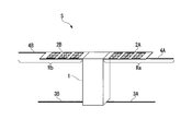
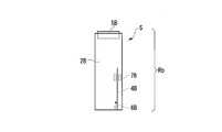
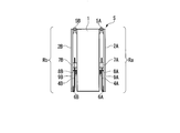
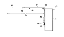
- this indication it is a mimetic diagram showing the state before deployment of a solar cell panel of a small satellite. In one embodiment of this indication, it is a mimetic diagram showing the state after deployment of the solar cell panel of a small satellite. In one embodiment of this indication, it is a mimetic diagram showing the state before deployment of a solar cell panel of a small satellite. In one embodiment of this indication, it is a mimetic diagram showing the state before deployment of a solar cell panel of a small satellite. In one embodiment of this indication, it is a mimetic diagram showing the state after deployment of the solar cell panel of a small satellite. In one embodiment of this indication, it is a mimetic diagram showing the state after deployment of the solar cell panel of a small satellite.
- the micro-satellite S has a substantially box shape before the solar cell panels 2A and 2B are deployed, and has a weight of several kg to 100 kg.
- this micro-satellite S includes a satellite body 1 and a pair of solar cell panels 2A and 2B as external components.
- the satellite body 1 is of a substantially box shape (substantially rectangular parallelepiped), and has a built-in device that differs depending on the application of the micro-satellite S, but contains a communication device and various measuring devices.
- the lower side (bottom surface) faces the ground (earth) while the microsatellite S is flying in the orbit of the earth, for example. It is the side (face).
- a pair of solar cell panels 2A and 2B are provided dispersedly on the left and right of the satellite body 1 as described above. That is, of the pair of solar cell panels 2A and 2B, the solar cell panel 2A is provided on the left side surface (substantially plane) of the satellite body 1 and the solar cell panel 2B is provided on the right side surface (substantially plane) of the satellite body 1. ing.
- a plurality of solar cells are provided on the surface of a flat support plate, and power is supplied to the satellite body 1.
- the support plate is made of a conductive material.
- the pair of solar cell panels 2A and 2B are rectangular and flat plate members that are formed in the same shape and have a long side and a short side of a predetermined length. That is, it can be said that the pair of solar cell panels 2A and 2B have a shape extending in one direction in which the long sides extend.
- the solar cell panel 2A of the pair of solar cell panels 2A and 2B is provided so as to face the left side surface of the satellite body 1 in parallel, and the solar cell panel 2B is the satellite. It is provided so as to face the right side surface of the main body 1 in parallel.
- such a micro-satellite S has a pair of solar cell panels 2A and 2B protruding to the left and right of the satellite body 1 in the state where the solar cell panels 2A and 2B have been deployed, and the satellite body is also the same.
- a pair of radiators 3A and 3B project to the left and right of 1.
- the pair of solar cell panels 2A and 2B are located on the rear side of the satellite body 1 when the earth side (lower side) of the satellite body 1 is the front side.
- the pair of radiators 3A and 3B are rod-shaped members made of a conductive material and are located on the front side of the satellite body 1. That is, the pair of solar cell panels 2A and 2B in the deployed state of the solar cell panels 2A and 2B are located rearward of the pair of radiators 3A and 3B in the satellite body 1 (micro satellite S).
- the pair of solar cell panels 2A and 2B are in a posture substantially orthogonal to the satellite body 1 in the deployed state of the solar cell panels 2A and 2B. That is, the solar cell panel 2A projects leftward at an angle of approximately 90° with respect to the left side surface of the satellite body 1, and the solar cell panel 2B rightward at an angle of approximately 90° with respect to the right side surface of the satellite body 1. Project toward. Therefore, each of the pair of solar cell panels 2A and 2B projects left and right in a posture substantially orthogonal to the satellite body 1 and is arranged in a substantially straight line with the satellite body 1 interposed therebetween.
- the angle of approximately 90° does not necessarily mean that the angle is completely 90°, but means that the angle is approximately 90°.
- Rod-shaped members 4A and 4B are linearly connected to the tip of each of the pair of solar cell panels 2A and 2B. These rod-shaped members 4A and 4B are conductors that are formed of a conductive material and project on the extension lines of the pair of solar cell panels 2A and 2B when the solar cell panels 2A and 2B are deployed. Such rod-shaped members 4A and 4B are auxiliary components for adjusting the length of the pair of solar cell panels 2A and 2B as conductors.
- the rod-shaped members 4A and 4B may be provided on the extension lines of the long sides of the solar cell panels 2A and 2B as shown in FIG. 1B, but as shown in FIG. 2A and FIG. 4A and 4B do not have to be provided on the extension lines of the long sides of the solar cell panels 2A and 2B.
- the rod-shaped member 4A is linearly connected to the tip of the solar cell panel 2A, and the total length of the solar cell panel 2A and the rod-shaped member 4A as a conductor is set to a predetermined length.
- a rod-shaped member 4B is linearly connected to the tip of the solar cell panel 2B, and the total length of the solar cell panel 2B and the rod-shaped member 4B as a conductor is set to a predetermined length.
- each of the rod-shaped members 4A and 4B is mechanically and electrically connected to each support plate of the solar cell panels 2A and 2B.
- the rod-shaped members 4A and 4B form a pair of reflectors Ra and Rb together with the support plates of the solar cell panels 2A and 2B. That is, the solar cell panel 2A and the rod-shaped member 4A form a reflector Ra having a predetermined length, and the solar cell panel 2B and the rod-shaped member 4B also form a reflector Rb having a predetermined length.
- the pair of reflectors Ra and Rb, together with the pair of radiators 3A and 3B, form an artificial satellite antenna according to this embodiment, and assist the pair of radiators 3A and 3B.
- the pair of reflectors Ra, Rb are orthogonal to the extending direction of the rod-shaped member 4A or 4B, and the solar cell When viewed from a direction parallel to the panel 2A or 2B, it has a substantially linear shape (a substantially linear shape).
- substantially linear substantially linear
- the term “substantially linear (substantially linear)” does not necessarily mean that it is completely linear (straight), but may be approximately linear (substantially linear).
- Each of the pair of radiators 3A and 3B is a unipole antenna, and is connected to the communication device in the satellite body 1. That is, of the pair of radiators 3A and 3B, the radiator 3A is one unipole antenna and faces the reflector Ra in parallel. The radiator 3B is the other unipole antenna and faces the reflector Rb in parallel.
- Such a pair of radiators 3A and 3B are housed between the side surface of the satellite body 1 and the pair of solar cell panels 2A and 2B when the solar cell panels 2A and 2B are not deployed, At the time of deployment, it is deployed in the same direction as the deployment direction of the pair of solar cell panels 2A, 2B. That is, when the solar cell panels 2A and 2B are not deployed, the radiator 3A is housed between the left side surface of the satellite body 1 and the solar cell panel 2A, and the radiator 3B is located between the right side surface of the satellite body 1 and the sun. It is housed between battery panel 2B.
- the radiator 3A deploys in the same direction as the deployment direction of the solar cell panel 2A
- the radiator 3B deploys in the same direction as the deployment direction of the solar cell panel 2B. That is, the pair of reflectors Ra and Rb and the pair of radiators 3A and 3B have a positional relationship in which they face each other in parallel when the solar cell panels 2A and 2B are deployed.
- the radiator 3A faces the reflector Ra in parallel
- the radiator 3B faces the reflector Rb in parallel.
- the reflector Ra and the radiator 3A are linear and substantially parallel to each other.
- the reflector Rb is viewed from a direction orthogonal to the extending direction of the rod-shaped member 4B and parallel to the solar cell panel 2B
- the reflector Rb and the radiator 3B are linear and substantially parallel to each other. ..
- the above relationship holds when the thicknesses of the solar cell panels 2A and 2B and the diameters of the rod-shaped members 4A and 4B are substantially the same.
- the pair of solar cell panels 2A and 2B project left and right in a posture substantially orthogonal to the satellite body 1 and are arranged in a substantially straight line with the satellite body 1 interposed therebetween, the pair of reflectors Ra , Rb and the pair of radiators 3A and 3B have a linear shape substantially parallel to each other.
- a pair of deploying devices (not shown) for deploying the pair of undeployed radiators 3A and 3B are individually provided.
- substantially parallel means that it is not always required to be completely parallel, but may be substantially parallel.
- FIGS. 2A and 2B are schematic diagrams showing the solar cell panels 2A and 2B of the satellite main body 1 before being deployed
- FIGS. 3A and 3B show the solar battery panels 2A and 2B of the satellite main body 1.
- It is a schematic diagram which shows the state after expansion
- the pair of reflectors Ra and Rb are representative of the pair of reflectors Ra and Rb in FIGS. 2A, 3A, and 3B. Only Rb is shown. 2A, 2B, 3A, and 3B, FIG. 2A shows a state before the reflector Rb is unfolded, and FIG. 2B shows a state before the pair of reflectors Ra and Rb is unfolded. ..
- FIG. 2A is a front view of the reflector Rb
- FIG. 2B is a side view of the pair of reflectors Ra and Rb.
- 3A and 3B show a state after the reflector Rb is expanded
- FIG. 3A is a front view of the reflector Rb
- FIG. 3B is a side view of the reflector Rb.
- the pair of solar cell panels 2A, 2B which are the constituent elements of the pair of reflectors Ra, Rb, are located on the rear side of the satellite body 1 (micro satellite S).
- the ends of the solar cell panels 2A and 2B located at are rotatably connected to the side surface of the satellite body 1 by a pair of hinges 5A and 5B.
- the pair of hinges 5A, 5B includes a rotation axis parallel to the rear end surface of the satellite body 1 and the rear end sides of the pair of solar cell panels 2A, 2B, and has a pair of solar cell panels 2A, 2B within a predetermined rotation range. Is a connector for rotatably connecting to the side surface of the satellite body 1.
- the hinge 5A has a rotation axis parallel to the rear end face of the satellite body 1 and the rear end side of the solar cell panel 2A, and the solar cell panel 2A is rotatably on the left side of the satellite body 1.
- the hinge 5B has a rotation axis parallel to the rear end surface of the satellite body 1 and the rear end side of the solar cell panel 2B, and rotatably connects the solar cell panel 2B to the right side surface of the satellite body 1.
- the hinges 5A and 5B store the solar cell panels 2A and 2B in a posture parallel to the side surface of the satellite body 1 when the solar cell panels 2A and 2B are not deployed. Further, biasing members such as springs are incorporated in the rotary shafts of the hinges 5A and 5B.
- the hinges 5A and 5B have a maximum rotation angle of about 90°, that is, the solar cell panels 2A and 2B are in a posture substantially orthogonal to the side surface of the satellite body 1 by the biasing force of the biasing member acting as a starting force.
- the solar cell panels 2A and 2B are developed so that
- the rod-shaped members 4A and 4B are connected to the tip ends of the solar cell panels 2A and 2B via elastic materials (connection springs) 6A and 6B. That is, of the elastic members 6A and 6B, the elastic member 6A is provided at the tip of the solar cell panel 2A and connects the rod-shaped member 4A to the solar cell panel 2A flexibly.
- the elastic material 6B is provided at the tip of the solar cell panel 2B, and flexibly connects the rod-shaped member 4B to the solar cell panel 2B.
- the elastic members 6A and 6B are, for example, coil springs or leaf springs, and the rod-shaped members 4A and 4B are bent with respect to the solar cell panels 2A and 2B when the solar cell panels 2A and 2B are not expanded.
- the rod-shaped members 4A and 4B are housed between the solar cell panels 2A and 2B, that is, between the solar cell panels 2A and 2B and the side surface of the satellite body 1. Further, the elastic members 6A and 6B expand the rod-shaped members 4A and 4B in a state where the rod-shaped members 4A and 4B are extended substantially straight with respect to the solar cell panels 2A and 2B when the solar cell panels 2A and 2B are expanded.
- substantially straight line does not necessarily mean that the line is a perfect straight line, but may be a substantially straight line.
- holding members 7A and 7B are provided corresponding to the rod-shaped members 4A and 4B. That is, the holding member 7A is provided on the left side surface of the satellite body 1 corresponding to the rod-shaped member 4A, and the holding member 7B is provided on the right side surface of the satellite body 1 corresponding to the rod-shaped member 4B.
- Such holding members 7A and 7B are members that perform positioning when the rod-shaped members 4A and 4B are stored, and hold a part of the rod-shaped members 4A and 4B.
- a holding line 8A is provided between the left side surface of the satellite body 1 and the solar cell panel 2A so as to correspond to the solar cell panel 2A, and between the right side surface of the satellite body 1 and the solar cell panel 2B.
- a holding line 8B is provided corresponding to the solar cell panel 2B.
- Such holding lines 8A and 8B are connection lines for maintaining the solar cell panels 2A and 2B and the rod-shaped members 4A and 4B in a non-deployed state.
- Such holding lines 8A and 8B are individually blown by the cutting devices 9A and 9B individually provided on the side surface of the satellite body 1.
- the cutting device 9A melts the holding wire 8A by heating it to a predetermined temperature (melting temperature), and the cutting device 9B heats the holding wire 8B to a predetermined temperature (melting temperature). To melt down.
- the holding members 7A and 7B, the holding lines 8A and 8B, and the cutting devices 9A and 9B form a holding unit according to the present disclosure.
- the pair of cutting devices 9A and 9B actuate to move the pair of solar cell panels 2A and 2B and the rod-shaped members 4A and 4B from the undeployed state to the deployed state. That is, when the pair of cutting devices 9A and 9B are actuated to melt the pair of holding lines 8A and 8B, the urging force of the urging member incorporated in the rotating shafts of the pair of hinges 5A and 5B is used as the activating force. It acts on the solar cell panels 2A and 2B.
- the pair of solar cell panels 2A and 2B facing each other in parallel to the side surface of the satellite body 1 in the non-deployed state are deployed in a state substantially orthogonal to the side surface of the satellite body 1 by the biasing force (starting force).
- the elastic force of the pair of elastic members 6A, 6B acts on the pair of rod-shaped members 4A, 4B as a starting force, so that the pair of solar cell panels 2A, 2B in the undeployed state.
- the pair of rod-shaped members 4A and 4B that are in a bent state with respect to 2B expand in the same direction as the pair of solar cell panels 2A and 2B by the elastic force (starting force).
- the pair of deployment devices provided between the pair of radiators 3A, 3B and the satellite body 1 are activated.
- the pair of radiators 3A and 3B deploys in the same direction as the deployment direction of the pair of solar cell panels 2A and 2B and the rod-shaped members 4A and 4B.
- the pair of reflectors Ra, Rb constituted by the pair of solar cell panels 2A, 2B and the rod-shaped members 4A, 4B are the pair of radiators. It is in a state of facing in parallel with 3A and 3B. Further, the reflector Ra formed by the solar cell panel 2A and the rod-shaped member 4A is an integral conductor, and the reflector Rb formed by the solar cell panel 2B and the rod-shaped member 4B is also an integral conductor.
- the length of the pair of reflectors Ra and Rb is optimized for the wavelength of the radio wave when the pair of radiators 3A and 3B communicate with the earth. That is, the total length of the solar cell panel 2A and the rod-shaped member 4A is set to a length corresponding to a quarter wavelength of the radio wave transmitted and received by the radiator 3A, and the total length of the solar cell panel 2B and the rod-shaped member 4B. The length is set to a length corresponding to a quarter wavelength of the radio wave transmitted and received by the radiator 3B.
- the reflector Ra effectively reflects the radio wave radiated from the earth to the microsatellite S toward the radiator 3A, so that the reflector Ra and the radiator 3A are used.
- the antenna gain of the constructed satellite antenna is improved as compared with the conventional satellite antenna in which the reflector Ra does not exist.
- the reflector Ra shields noise electric waves coming from behind, and thus improves the SN ratio of the received wave received by the radiator 3A from the earth.
- the reflector Rb effectively reflects the radio wave radiated from the earth toward the radiator 3B
- the antenna gain of the artificial satellite antenna constituted by the reflector Rb and the radiator 3B is equal to the reflector Rb. This is an improvement over conventional satellite antennas that do not exist.
- the reflector Rb shields noise radio waves coming from behind, and thus improves the SN ratio of the received wave that the radiator 3B receives from the earth.
- the artificial satellite antenna is an artificial satellite antenna mounted on an artificial satellite (micro satellite S) including the satellite body 1, and includes the solar cell panels 2A and 2B and the radiator. 3A and 3B, and conductors (bar-shaped members 4A and 4B) mechanically and electrically connected to the solar cell panels 2A and 2B, and the solar cell panels 2A and 2B and conductors (bar-shaped members 4A and 4B). It is used as the reflectors Ra and Rb. That is, since the pair of solar cell panels 2A and 2B function as the pair of reflectors Ra and Rb only by adding the pair of rod-shaped members 4A and 4B to the pair of solar cell panels 2A and 2B, it is possible to increase the weight and volume. It is possible to improve the antenna performance while suppressing.
- the present disclosure is not limited to the above embodiment, and may be modified examples as below.
- the pair of radiators 3A and 3B are configured as unipole antennas, but the present disclosure is not limited to this.
- the pair of radiators 3A and 3B may be configured as a bipole antenna.
- the present disclosure is applied to the micro satellite S, but the present disclosure is not limited to this.
- the weight of the artificial satellite to which the present disclosure is applied is not limited to the microsatellite S, and may be applied to a small satellite having a weight of 100 kg to 1000 kg, or an artificial satellite having a heavier weight than the small satellite.
- the rotation axes of the pair of hinges 5A and 5B are set in the posture parallel to the rear end surface of the satellite body 1, but the present disclosure is not limited to this.
- the rotation axes of the pair of hinges 5A and 5B may be set in a posture that is not parallel to the rear end surface of the satellite body 1, for example, substantially orthogonal thereto.
- the pair of solar cell panels 2A and 2B are made into a pair of reflectors Ra and Rb by adding the rod-shaped members 4A and 4B to the pair of solar cell panels 2A and 2B, respectively.
- the disclosure is not limited to this.
- the rod-shaped members 4A, 4B are provided on each solar cell panel 2A, 2B.
- an artificial satellite having one solar cell panel is provided.
- one rod-shaped member is provided.
- only one of the pair of rod-shaped members 4A and 4B may be provided to provide only one of the pair of reflectors Ra and Rb.
- connection structure between the pair of reflectors Ra and Rb and the satellite body 1 is not limited to the structure shown in FIGS. 2 and 3, and a known connection structure between the satellite body and the reflecting mirror is appropriately adopted. May be.
- the artificial satellite antenna of the present disclosure it is possible to improve antenna performance while suppressing an increase in weight and volume.
Landscapes
- Engineering & Computer Science (AREA)
- Remote Sensing (AREA)
- Aviation & Aerospace Engineering (AREA)
- Physics & Mathematics (AREA)
- General Physics & Mathematics (AREA)
- Astronomy & Astrophysics (AREA)
- Life Sciences & Earth Sciences (AREA)
- Sustainable Development (AREA)
- Environmental Sciences (AREA)
- General Health & Medical Sciences (AREA)
- Toxicology (AREA)
- Environmental & Geological Engineering (AREA)
- Biodiversity & Conservation Biology (AREA)
- Health & Medical Sciences (AREA)
- Aerials With Secondary Devices (AREA)
- Photovoltaic Devices (AREA)
- Superconductors And Manufacturing Methods Therefor (AREA)
- Details Of Aerials (AREA)
Abstract
Description
本願は、2018年12月13日に日本国に出願された特願2018-233556号に基づき優先権を主張し、その内容をここに援用する。
特許文献2と特許文献3にも人工衛星が開示されている。
最初に、本実施形態に係る人工衛星用アンテナが搭載される人工衛星(超小型衛星S)について、図1A,図1Bを参照して説明する。この超小型衛星Sは、図1Aに示すように、太陽電池パネル2A,2Bの展開前の状態では略箱型であり、数kg~100kg程度の重量を持つ。
ここで、略90°の角度とは、必ずしも完全に90°の角度である必要はなく、概略90°の角度であるという意味である。
ここで、棒状部材4A,4Bは、図1Bに示すように、太陽電池パネル2A,2Bの長辺の延長線上に設けられていても良いが、図2Aや図3Aに示すように、棒状部材4A,4Bが、太陽電池パネル2A,2Bの長辺の延長線上に設けられていなくても良い。
ここで、太陽電池パネル2A,2Bの厚さと棒状部材4A,4Bの直径が略同一の場合、一対の反射器Ra,Rbは、棒状部材4A又は4Bの延びる方向に直交し、かつ、太陽電池パネル2A又は2Bに平行な方向から見ると、略線状(略直線状)に構成されている。ここで、略線状(略直線状)とは、必ずしも完全に線状(直線状)である必要はなく、概略線状(概略直線状)であればよいという意味である。
従って、一対の太陽電池パネル2A,2Bが、衛星本体1に対して略直交する姿勢で左右に突出すると共に、衛星本体1を挟んで略直線状に配置されているため、一対の反射器Ra,Rbと一対の輻射器3A,3Bとは、互いに略平行な線状となる。
なお、このような一対の輻射器3A,3Bと衛星本体1との間には、非展開状態の一対の輻射器3A,3Bを展開状態とする一対の展開装置(図示略)が個別に設けられている。
ここで、略平行とは、必ずしも完全に平行である必要はなく、概略平行であれば良いという意味である。
(1)上記実施形態では、一対の輻射器3A,3Bをユニポールアンテナとして構成したが、本開示はこれに限定されない。例えば一対の輻射器3A,3Bをバイポールアンテナとして構成してもよい。
1 衛星本体
2A,2B 太陽電池パネル
3A,3B 輻射器
4A,4B 棒状部材
5A,5B ヒンジ
6A,6B 接続バネ
7A,7B 保持部材(保持部)
8A,8B 保持線(保持部)
9A,9B 切断装置(保持部)
Ra,Rb 反射器
Claims (8)
- 衛星本体を備える人工衛星に搭載される人工衛星用アンテナであって、
太陽電池パネルと、
輻射器と、
前記太陽電池パネルに機械的かつ電気的に接続される導体と、を備え、
前記太陽電池パネル及び前記導体を反射器として用いる人工衛星用アンテナ。 - 前記太陽電池パネルは、一方向に延びる形状を有し、
前記導体は、弾性材を介して前記太陽電池パネルに接続されているとともに、前記太陽電池パネルの展開時に前記一方向の延長線上に前記太陽電池パネルから突出する請求項1に記載の人工衛星用アンテナ。 - 前記導体は、前記太陽電池パネルの非展開時において前記太陽電池パネルに対して屈曲した状態で収容され、保持部によって前記衛星本体に保持されている請求項2に記載の人工衛星用アンテナ。
- 前記保持部は、前記太陽電池パネルの展開時に溶断される請求項3に記載の人工衛星用アンテナ。
- 前記太陽電池パネルが一対設けられる場合、前記導体は、各々の前記太陽電池パネルに設けられる請求項1~4のいずれか一項に記載の人工衛星用アンテナ。
- 前記導体は棒状部材である請求項1~5のいずれか一項に記載の人工衛星用アンテナ。
- 前記太陽電池パネルの展開時に、前記導体が延びる方向に直交し、かつ、前記太陽電池パネルに平行な方向から見ると、前記太陽電池パネルと前記導体とが略直線状となる請求項1~6のいずれか一項に記載の人工衛星用アンテナ。
- 前記太陽電池パネル及び前記導体は、前記人工衛星に放射された電波を、前記輻射器に向けて反射する反射器である請求項1~7のいずれか一項に記載の人工衛星用アンテナ。
Priority Applications (3)
| Application Number | Priority Date | Filing Date | Title |
|---|---|---|---|
| JP2020559742A JP7056763B2 (ja) | 2018-12-13 | 2019-09-20 | 人工衛星用アンテナ |
| CA3122945A CA3122945A1 (en) | 2018-12-13 | 2019-09-20 | Artificial-satellite antenna |
| US17/342,673 US12034205B2 (en) | 2018-12-13 | 2021-06-09 | Artificial-satellite antenna |
Applications Claiming Priority (2)
| Application Number | Priority Date | Filing Date | Title |
|---|---|---|---|
| JP2018-233556 | 2018-12-13 | ||
| JP2018233556 | 2018-12-13 |
Related Child Applications (1)
| Application Number | Title | Priority Date | Filing Date |
|---|---|---|---|
| US17/342,673 Continuation US12034205B2 (en) | 2018-12-13 | 2021-06-09 | Artificial-satellite antenna |
Publications (1)
| Publication Number | Publication Date |
|---|---|
| WO2020121621A1 true WO2020121621A1 (ja) | 2020-06-18 |
Family
ID=71077182
Family Applications (1)
| Application Number | Title | Priority Date | Filing Date |
|---|---|---|---|
| PCT/JP2019/036981 Ceased WO2020121621A1 (ja) | 2018-12-13 | 2019-09-20 | 人工衛星用アンテナ |
Country Status (4)
| Country | Link |
|---|---|
| US (1) | US12034205B2 (ja) |
| JP (1) | JP7056763B2 (ja) |
| CA (1) | CA3122945A1 (ja) |
| WO (1) | WO2020121621A1 (ja) |
Cited By (1)
| Publication number | Priority date | Publication date | Assignee | Title |
|---|---|---|---|---|
| TWI888952B (zh) * | 2023-10-11 | 2025-07-01 | 智探太空股份有限公司 | 立方衛星 |
Families Citing this family (1)
| Publication number | Priority date | Publication date | Assignee | Title |
|---|---|---|---|---|
| US12006071B1 (en) * | 2021-03-04 | 2024-06-11 | Government Of The United States As Represented By The Secretary Of The Air Force | Deployable radiator panel system |
Citations (2)
| Publication number | Priority date | Publication date | Assignee | Title |
|---|---|---|---|---|
| JP2008221876A (ja) * | 2007-03-08 | 2008-09-25 | Mitsubishi Electric Corp | 人工衛星搭載用太陽電池パネル、及び人工衛星 |
| JP2014019238A (ja) * | 2012-07-17 | 2014-02-03 | Kagawa Univ | 人工衛星 |
Family Cites Families (4)
| Publication number | Priority date | Publication date | Assignee | Title |
|---|---|---|---|---|
| US6394395B1 (en) * | 2000-03-15 | 2002-05-28 | Lockheed Martin Corporation | Combination solar array assembly and antenna for a satellite |
| JP2007221303A (ja) | 2006-02-15 | 2007-08-30 | Mitsubishi Electric Corp | 衛星通信アンテナ装置 |
| US9637248B2 (en) | 2013-03-15 | 2017-05-02 | The Boeing Company | Component deployment system |
| JP6448293B2 (ja) | 2014-03-05 | 2019-01-09 | ザ・ボーイング・カンパニーThe Boeing Company | 構造部材展開システム |
-
2019
- 2019-09-20 JP JP2020559742A patent/JP7056763B2/ja active Active
- 2019-09-20 WO PCT/JP2019/036981 patent/WO2020121621A1/ja not_active Ceased
- 2019-09-20 CA CA3122945A patent/CA3122945A1/en not_active Abandoned
-
2021
- 2021-06-09 US US17/342,673 patent/US12034205B2/en active Active
Patent Citations (2)
| Publication number | Priority date | Publication date | Assignee | Title |
|---|---|---|---|---|
| JP2008221876A (ja) * | 2007-03-08 | 2008-09-25 | Mitsubishi Electric Corp | 人工衛星搭載用太陽電池パネル、及び人工衛星 |
| JP2014019238A (ja) * | 2012-07-17 | 2014-02-03 | Kagawa Univ | 人工衛星 |
Cited By (1)
| Publication number | Priority date | Publication date | Assignee | Title |
|---|---|---|---|---|
| TWI888952B (zh) * | 2023-10-11 | 2025-07-01 | 智探太空股份有限公司 | 立方衛星 |
Also Published As
| Publication number | Publication date |
|---|---|
| CA3122945A1 (en) | 2020-06-18 |
| JPWO2020121621A1 (ja) | 2021-09-30 |
| JP7056763B2 (ja) | 2022-04-19 |
| US20210296763A1 (en) | 2021-09-23 |
| US12034205B2 (en) | 2024-07-09 |
Similar Documents
| Publication | Publication Date | Title |
|---|---|---|
| JPH0633697Y2 (ja) | 多通信系衛星軌道宇宙船 | |
| JP6024061B2 (ja) | 大型かつ堅牢な展開可能構造物およびそのような構造物の展開および係止方法 | |
| Gao et al. | Advanced antennas for small satellites | |
| JP6419180B2 (ja) | 並列デュアルロンチ機構 | |
| JP7056763B2 (ja) | 人工衛星用アンテナ | |
| US20180151938A1 (en) | Easyly deployable phased antenna for a spacecraft and system of such antennas | |
| JP2002308199A (ja) | 展開可能な宇宙船用放熱器 | |
| US7755564B2 (en) | Deployable phasing system for emulating reflective surfaces | |
| JP2005514270A5 (ja) | ||
| JP2008221876A (ja) | 人工衛星搭載用太陽電池パネル、及び人工衛星 | |
| EP3087007A1 (en) | Space vehicle | |
| JP2001060812A (ja) | 二反射器システムの展開 | |
| US9065173B2 (en) | Multiple-reflector antenna for telecommunications satellites | |
| US11912440B2 (en) | Partially flexible solar array structure | |
| US20090109123A1 (en) | System and Method for Providing a Deployable Phasing Structure | |
| Uddin et al. | The Evolutions of Reflectarray Antennas for Small Satellites: Navigating to Design, Fabrication and Performance Techniques | |
| JP2003276698A (ja) | 人工衛星 | |
| CN117832805A (zh) | 天线组件及终端设备 | |
| JPH068120B2 (ja) | 静止通信衛星 | |
| KR102730079B1 (ko) | 안테나 구속분리 장치 및 안테나 구속분리 방법 | |
| KR101537326B1 (ko) | 전파 지향 구동 장치 | |
| EP0838877A2 (en) | Deployable reflectors | |
| Essoumati et al. | Study and Design of a Reliable Antenna Deployment System for Nanosatellites | |
| JP2021091297A (ja) | 人工衛星 | |
| WO2026069081A1 (en) | Deployable space antenna with rollable and/or z-foldable reflector array |
Legal Events
| Date | Code | Title | Description |
|---|---|---|---|
| 121 | Ep: the epo has been informed by wipo that ep was designated in this application |
Ref document number: 19897389 Country of ref document: EP Kind code of ref document: A1 |
|
| ENP | Entry into the national phase |
Ref document number: 2020559742 Country of ref document: JP Kind code of ref document: A |
|
| ENP | Entry into the national phase |
Ref document number: 3122945 Country of ref document: CA |
|
| NENP | Non-entry into the national phase |
Ref country code: DE |
|
| 122 | Ep: pct application non-entry in european phase |
Ref document number: 19897389 Country of ref document: EP Kind code of ref document: A1 |