WO2020121456A1 - Microscope, adjustment device for microscope, microscope system, method for controlling microscope, and program - Google Patents
Microscope, adjustment device for microscope, microscope system, method for controlling microscope, and program Download PDFInfo
- Publication number
- WO2020121456A1 WO2020121456A1 PCT/JP2018/045774 JP2018045774W WO2020121456A1 WO 2020121456 A1 WO2020121456 A1 WO 2020121456A1 JP 2018045774 W JP2018045774 W JP 2018045774W WO 2020121456 A1 WO2020121456 A1 WO 2020121456A1
- Authority
- WO
- WIPO (PCT)
- Prior art keywords
- image
- state
- observation target
- unit
- optical system
- Prior art date
Links
Images


Classifications
-
- G—PHYSICS
- G02—OPTICS
- G02B—OPTICAL ELEMENTS, SYSTEMS OR APPARATUS
- G02B21/00—Microscopes
- G02B21/18—Arrangements with more than one light path, e.g. for comparing two specimens
- G02B21/20—Binocular arrangements
- G02B21/22—Stereoscopic arrangements
-
- G—PHYSICS
- G02—OPTICS
- G02B—OPTICAL ELEMENTS, SYSTEMS OR APPARATUS
- G02B7/00—Mountings, adjusting means, or light-tight connections, for optical elements
- G02B7/28—Systems for automatic generation of focusing signals
-
- H—ELECTRICITY
- H04—ELECTRIC COMMUNICATION TECHNIQUE
- H04N—PICTORIAL COMMUNICATION, e.g. TELEVISION
- H04N13/00—Stereoscopic video systems; Multi-view video systems; Details thereof
- H04N13/20—Image signal generators
- H04N13/204—Image signal generators using stereoscopic image cameras
- H04N13/239—Image signal generators using stereoscopic image cameras using two 2D image sensors having a relative position equal to or related to the interocular distance
-
- H—ELECTRICITY
- H04—ELECTRIC COMMUNICATION TECHNIQUE
- H04N—PICTORIAL COMMUNICATION, e.g. TELEVISION
- H04N7/00—Television systems
- H04N7/18—Closed-circuit television [CCTV] systems, i.e. systems in which the video signal is not broadcast
Definitions
- the technology of the present disclosure relates to a microscope, a microscope adjusting device, a microscope system, a microscope control method, and a program.
- Japanese Patent No. 5886827 identifies the corresponding features in the right-eye image and the left-eye image and determines the direction and/or magnitude of the displacement vector defined from the identified features in the right-eye image and the identified features in the left-eye image.
- An optical stereo device for adjusting the focus position based on the above is disclosed. Generally, it has been conventionally desired to accurately adjust the in-focus position of a microscope.
- a microscope forms a right-side observation target light obtained from an observation target on a right-side imaging device, and forms a left-side observation target light obtained from the observation target on a left-side imaging device.
- An optical system an adjusting unit that adjusts a focus position of the optical system with respect to the observation target, a right side image obtained by the right side imaging device based on the right side observation target light, and a left side observation by the left side imaging device
- a deriving unit for deriving a correlation with the left image obtained based on the target light by a phase-only correlation method, and the adjusting unit so that the focusing position is adjusted based on the correlation derived by the deriving unit.
- a control unit for controlling.
- a microscope is a right-side observation optical system that forms a right-side observation target light obtained from an observation target on a right-side imaging device, and a left-side observation target light obtained from the observation target is a left-side imaging device.
- An optical system including a left-side observation optical system for forming an image, a change unit for changing the substantial angle formed by the optical axis of the right-side observation target light and the optical axis of the left-side observation target light at the position of the observation target, An adjusting unit that adjusts a focus position of the optical system with respect to the observation target, a right image obtained by the right imaging device based on the right observation light, and a left image based on the left observation light.
- the derivation unit that derives an evaluation value indicating the degree of focusing on at least one of the left images obtained by the defocusing, and the focusing position is adjusted based on the evaluation value derived by the derivation unit.
- a control unit for controlling the adjusting unit.
- a microscope adjusting device forms a right-side observation target light obtained from an observation target on a right-side imaging device, and a left-side observation target light obtained from the observation target.
- An adjusting unit that adjusts a focus position of the optical system for focusing on the observation target, a right-side image generated based on the right-side observation target light, and a left-side image generated based on the left-side observation target light.
- a controller that controls the adjusting unit so that the focus position is adjusted based on the correlation derived by the deriving unit.
- a microscope adjusting device provides a right-side observation optical system that forms a right-side observation target light obtained from an observation target on a right-side imaging device, and a left-side observation target light obtained from the observation target.
- a left-side observation optical system for forming an image on the left-side imaging device; and a changing unit for changing a substantial angle formed by the optical axis of the right-side observation target light and the optical axis of the left-side observation target light at the position of the observation target.
- An adjusting unit that adjusts a focus position of the optical system with respect to the observation target, a right side image generated based on the right side observation target light, and a left side image generated by being imaged based on the left side observation target light.
- a derivation unit that derives an evaluation value indicating the degree of focus for at least one of the two, and the adjustment unit so that the focus position is adjusted based on the evaluation value derived by the derivation unit.
- a control unit for controlling.
- FIG. 6 is a screen diagram showing an observation screen when the AF mode is set in the present embodiment. It is a functional block diagram which shows the function of the surgical microscope when AF mode is set in this embodiment. It is a schematic image figure which shows the image obtained by performing a two-dimensional discrete Fourier transform with respect to the right image in this embodiment. It is a schematic image figure which shows the image obtained by performing a two-dimensional discrete Fourier transform with respect to the left image in this embodiment. It is an aspect figure which shows the aspect which displayed the phase-only correlation function in this Embodiment in three-dimensional form.
- FIG. 6 is an explanatory diagram for explaining a shift amount from a current focus position to a focus surface in the present embodiment. It is explanatory drawing with which the shift amount of the right side operative field image and left side operative field image and the shift amount of a right side image and a left side image in this embodiment are demonstrated. It is a screen figure which shows the state in which the focus position designation guide information was displayed in the observation screen in this embodiment.
- FIG. 7 is a screen view showing a mode in which the sample surgical field image displayed in the observation screen in this embodiment is divided into a plurality of regions.
- FIG. 6 is a schematic image diagram showing an alpha blended image when the outer edge of the iris is in focus in the present embodiment.
- FIG. 7 is a schematic image diagram showing an alpha blend image when the outer edge of the pupil is in focus in the present embodiment.
- FIG. 7 is a screen view showing a state in which a split image and upward movement required amount information are displayed in the observation screen in the present embodiment.
- FIG. 6 is a screen view showing a state in which a right side image, a left side image, a right side contrast value indicator, and a left side contrast value indicator are displayed in live view on the observation screen in the present embodiment. It is a schematic image figure which shows the right side image and the right side contrast value indicator which penetrated the lens for right eyes in this embodiment. It is a schematic image figure which shows the left side image and left side contrast value indicator which penetrated the lens for left eyes in this embodiment.
- FIG. 6 is a screen view showing a state in which a right side image, a left side image, and a contrast value indicator are live-view displayed in the observation screen in the present embodiment.
- FIG. 6 is a screen view showing an observation screen including a contrast confirmation screen on which a right side image and a right side contrast value indicator are displayed and a stereoscopic image display screen according to the present embodiment.
- FIG. 6 is a screen view showing an observation screen including a contrast confirmation screen on which a left image and a left contrast value indicator are displayed and a stereoscopic image display screen according to the present embodiment.
- FIG. 6 is a screen view showing an observation screen including a right-side image, a right-side contrast value indicator, a left-side image, and a contrast confirmation screen on which a left-side contrast value indicator is displayed and a stereoscopic image display screen according to the present embodiment.
- FIG. 6 is a screen view showing an observation screen including a right-side image, a right-side contrast value indicator, a left-side image, and a contrast confirmation screen on which a left-side contrast value indicator is displayed and a stereoscopic image display screen according to the present embodiment.
- FIG. 6 is a screen view showing a state in which a right side image, a right side contrast value graph, a left side image, and a left side contrast value graph in the present embodiment are displayed in live view.
- FIG. 5 is a schematic image diagram showing a right-side image and a right-side contrast value graph that are transmitted through the right-eye lens in the present embodiment.
- FIG. 6 is a schematic image diagram showing a left-side image and a left-side contrast value graph that have passed through the left-eye lens in the present embodiment.
- FIG. 7 is a screen view showing a state in which a right-side image, a left-side image, and a contrast value graph in the present embodiment are displayed in live view.
- FIG. 5 is a schematic image diagram showing a right-side image and a right-side contrast value graph that are transmitted through the right-eye lens in the present embodiment.
- FIG. 6 is a schematic image diagram showing a left-side image and a left-side contrast value graph that have passed through the left
- FIG. 6 is a screen diagram showing a contrast change confirmation screen on which a right-side image and a right-side contrast value graph are displayed and a stereoscopic image display screen as an observation screen.
- FIG. 5 is a screen view showing a viewing screen for a contrast change confirmation screen on which a left-side image and a left-side contrast value graph are displayed and a stereoscopic image display screen in the present embodiment.
- FIG. 6 is a screen diagram showing a viewing screen for a stereoscopic image display screen and a contrast change confirmation screen on which a right side image, a right side contrast value graph, a left side image, and a left side contrast value graph are displayed in the present embodiment.
- FIG. 5 is a screen view showing a viewing screen for a contrast change confirmation screen on which a left-side image and a left-side contrast value graph are displayed and a stereoscopic image display screen in the present embodiment.
- FIG. 6 is a screen diagram showing a viewing screen for a stereoscopic image display
- FIG. 9 is a screen view showing a state in which a contrast value on the right contrast value graph is designated by an arrow pointer on the observation screen in the present embodiment.
- FIG. 7 is a screen view showing a state in which the first to sixth focus support information and the live view images of the right side image and the left side image are displayed in the observation screen in the present embodiment.
- It is a flow chart which shows a flow of focus mode setting processing in this embodiment.
- It is a flow chart which shows a flow of peak coordinate specific processing in this embodiment.
- FIG. 9 is a screen diagram in a state where an AF mode is set on the observation screen according to the second embodiment. It is a screen figure in the state where MF mode was set up in the screen for observation concerning a 2nd embodiment.
- FIG. 6 is an explanatory diagram for explaining a shift amount from a current focus position to a focus surface in the present embodiment.
- the CPU means the abbreviation of "Central Processing Unit”.
- the RAM is an abbreviation of “Random Access Memory”.
- the ROM is an abbreviation for “Read Only Memory”.
- ASIC is an abbreviation for “Application Specific Integrated Circuit”.
- PLD is an abbreviation for "Programmable Logic Device”.
- FPGA is an abbreviation of “Field-Programmable Gate Array”.
- SSD refers to the abbreviation of “Solid State Drive”.
- DVD-ROM is an abbreviation of “Digital Versatile Disc Read Only Memory”.
- USB is an abbreviation for “Universal Serial Bus”.
- the HDD is an abbreviation for “Hard Disk Drive”.
- the EEPROM is an abbreviation of “Electrically Erasable and Programmable Read Only Memory”.
- the DRAM is an abbreviation of “Dynamic Random Access Memory”.
- SRAM refers to an abbreviation of “Static Random Access Memory”.
- the LSI is an abbreviation of “Large-Scale Integration”.
- CCD is an abbreviation for “Charge Coupled Device”.
- CMOS refers to an abbreviation of “Complementary Metal Oxide Semiconductor”.
- AF is an abbreviation for “Auto Focus”.
- MF is an abbreviation for “Manual Focus”.
- horizontal used in the following description includes not only perfect horizontal but also substantially horizontal meaning that includes an allowable error in design and manufacturing.
- vertical used in the following description includes not only complete verticality but also substantially vertical meaning that includes an allowable error in design and manufacturing.
- right angle includes an angle obtained by intersecting a horizontal line and a vertical line. Further, the term “right angle” used herein includes not only a perfect “right angle” but also a substantially right angle including an allowable error in design and manufacturing.
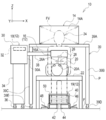
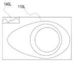
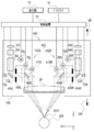
- FIG. 1 shows a surgery support system 10.
- the surgery support system 10 is an example of a microscope system according to the technique of the present disclosure.
- the surgery support system 10 includes a surgical microscope 12 and a display 14.
- the surgical microscope 12 is an example of a microscope according to the technique of the present disclosure
- the display 14 is an example of a display unit according to the technique of the present disclosure.
- the surgical microscope 12 includes a surgical microscope main body 16, an adjusting device 18, and a reception device 19.
- the adjusting device 18 is an example of an adjusting unit and a microscope adjusting device according to the technique of the present disclosure.
- the operating microscope 12 includes an ophthalmic microscope applied to the operation or observation of the eye 20A of the patient 20, or a surgical microscope applied to the operation or observation of the affected part of the patient 20.
- a patient 20 to be observed by the operating microscope 12 is placed on an operating table 22 in an operable posture.
- the operable posture refers to, for example, a state of lying on the back.
- the user 24 of the surgery support system 10 mounts the patient 20 and the surgical microscope main body 16 from the top of the patient 20 with respect to the patient 20 and the surgical microscope main body 16 placed on the operating table 22 in an operable posture. They are facing each other in a downright position.
- the user 24 refers to, for example, a surgeon, but the technique of the present disclosure is not limited to this.
- the user 24 may be an assistant who assists the work of the surgeon from the side or the back of the surgeon.
- the surgical microscope body 16 includes an objective lens 26.
- the optical axis direction of the objective lens 26 coincides with the vertical direction.
- the term “match” as used herein also includes an approximate match in the sense of including an allowable error in design and manufacturing.
- the objective lens 26 has an objective surface 26A facing the outside of the surgical microscope body 16.
- the objective surface 26A includes the lens surface of the objective lens 26 that is closest to the surgical field 28 side. Further, the objective surface 26A is an incident surface on which the observation light reflected by a predetermined part of the patient 20 is incident, and is also a lens surface on which the reflected light from the operative field 28 is incident.
- the adjusting device 18 includes an adjusting device main body 30, a control device 32, a support base 34, casters 36, and a support arm 38.
- the support base 34 is formed in a columnar shape, and a plurality of casters 36 are provided at the lower end of the support base 34.
- the adjustment device main body 30 is supported on the support base 34 so as to be slidable along the Z direction.
- the “Z direction” mentioned here refers to the vertical direction.
- the "X direction” refers to the horizontal direction
- the "Y direction” refers to the direction that is perpendicular to the two directions of the X direction and the Z direction.
- the adjustment device body 30 includes a rectangular parallelepiped housing 30A.
- a control device 32 is housed in the housing 30A.
- the control device 32 is a device that integrally controls the surgery support system 10.
- a columnar support arm 38 is attached to the side surface of the housing 30A. It projects from the side surface of the housing 30A along the horizontal direction. One end of the support arm 38 is fixed to the adjustment device body 30. The other end of the support arm 38 is fixed to the side surface of the housing 16A of the surgical microscope body 16. As a result, the surgical microscope main body 16 is supported by the adjusting device main body 30 from the side of the surgical microscope main body 16 via the support arm 38.
- the surgical microscope body 16 is arranged so that the objective surface 26A is located in front of the operative field 28 and below the line of sight of the user 24 located on the parietal side of the patient 20. That is, the line of sight of the user 24 is in a region in the positive direction of the Z axis with respect to the surgical microscope body 16 supported by the support arm 38.
- the surgical microscope body 16 arranged in this manner takes in the operative field light (observation light) that is the reflected light for the operative field 28 from the objective lens 26, and the operative field image (observation image, left side) based on the captured operative field light. Image and the right image).
- the operative field 28 an area including the eye 20A to be operated and the peripheral part of the eye 20A is illustrated, but the operative field 28 is not limited to this, and the operative field 28 is, for example, only the eye 20A. It may be present, or may be only a region recognized by the user 24 as a lesion in the eye 20A.
- the surgical field 28 may be a region that the user 24 has set as an observation target.
- the display 14 may be a liquid crystal display or an organic EL display.
- the display 14 is installed on the upper surface of the caster table 39 having a gate shape in a front view when viewed from the user 24 side.
- the caster table 39 includes a top plate 39A and legs 39B and 39C. Casters 39D are provided on the bottom surface of the leg portion 39B, and casters 39E are provided on the bottom surface of the leg portion 39C.
- the top plate 39A is formed along a horizontal plane.
- the top plate 39A is supported by the leg portion 39B from one end side and is supported by the leg portion 39C from the other end side. Therefore, the shape of the outline of the caster table 39 is a front view gate shape as viewed from the user 24 side by the top plate 39A and the legs 39B and 39C.
- the caster table 39 is arranged at the user front position P.
- the user front position P refers to a position which is located in front of the user 24 and which straddles the operating table 22 and the patient 20 placed on the operating table 22 in an operable posture.
- the abdomen of the patient 20 is located just below the top plate 39A
- the leg 39B is located on one side of the abdomen of the patient 20
- the leg 39C is located on the other side of the abdomen of the patient 20. It is arranged to be located.
- the surgical microscope 12 is arranged at a position outside the visual field region FV for the surgical field image while the user 24 is viewing the screen 14A from the front side of the surgical microscope main body 16.
- the visual field region FV refers to a spatial region of the screen of the user 24 in the state in which the user 24 is looking at the screen 14A from the front side of the surgical microscope main body 16 and is targeted for the screen 14A.
- the visual field region FV is determined based on the positional relationship between the pupil of the user 24 and the screen 14A.
- the reception device 19 includes a touch pad 40, a left click button 42, a right click button 44, an upward movement foot switch 46, and a downward movement foot switch 48.
- the touch pad 40, the left click button 42, and the right click button 44 are provided on the plate 50.
- the plate 50 is leaned against the floor surface F by a supporting member (not shown).
- the touch pad 40 is arranged at the center of the plate 50.
- the touch pad 40 receives an instruction from the user 24, for example, by detecting a position where the toes of the foot of the user 24 are in contact.
- a left click button 42 and a right click button 44 are arranged below the touch pad 40 in the plate 50.
- the left-click button 42 has the same function as the left-click button mounted on a general mouse.
- the right-click button 44 has the same function as the right-click button mounted on a general mouse.
- the left click button 42 and the right click button 44 are operated, for example, by the toes of the foot of the user 24.
- the upward movement foot switch 46 is a pedal type switch, and is depressed by the foot of the user 24 when moving the surgical microscope body 16 upward, that is, in the positive direction of the Z axis.
- the downward movement foot switch 48 is a pedal type switch, and is depressed by the foot of the user 24 when the surgical microscope main body 16 is moved downward, that is, in the negative direction of the Z axis.
- foot switches without reference numerals.
- the above-mentioned surgical field light is roughly classified into a right surgical field light showing the surgical field 28 and a left surgical field light showing the surgical field 28.
- the right operative field light is an example of the right observing target light according to the technique of the present disclosure
- the left operative field light is an example of the left observing target light according to the technique of the present disclosure.
- the “right side” refers to the right side when the surgical microscope main body 16 is viewed from the user 24, in other words, the positive direction of the X axis.
- the “left side” refers to the left side when the surgical microscope main body 16 is viewed from the user 24, in other words, the negative direction of the X axis.
- an operative field image showing the operative field 28 is generated as a parallax image by the right operative field light (right observing target light) and the left operative field light (left observing target light).
- the parallax image is a pair of images having parallax.
- the right operative field light is the operative field light for generating one of the pair of images having parallax
- the left operative field light is the other image of the pair of images having parallax. It is a light for surgery.
- One of the pair of images having parallax is an image for one eye of the user 24.
- the “image for one eye of the user 24” mentioned here is an example of a right image, and for example, refers to an image for the right eye which is an image for the right eye of the user 24.
- the other image of the pair of images having parallax is the image for the other eye of the user 24.
- the "image for the other eye of the user 24" here is an example of a left-side image, and indicates, for example, an image for the left eye that is an image for the left eye of the user 24.
- the parallax image is roughly divided into the right parallax image (in this case, the right image) and the left parallax image (in this case, the left image).
- the right parallax image is an image generated based on the right surgical field light
- the left parallax image is an image generated based on the left surgical field light. Since the right-side parallax image and the left-side parallax image are images having parallax, in the surgical microscope 12, the right-side parallax image and the left-side parallax image are displayed on the display 14 by the stereoscopic method, so that the surgical field image is displayed by the user 24. Is visually perceived as a stereoscopic image (parallax image).
- the “stereoscopic method” mentioned here includes, for example, a naked-eye method, a head-mounted display method, and an eyeglass method.
- Examples of the naked-eye method include a parallax barrier method and a lenticular lens method.
- the user 24 wears the head-mounted display. Then, the right parallax image displayed on the right eye display of the head mounted display is visually recognized by the right eye of the user 24, and the left parallax image displayed on the left eye display of the head mounted display is visually recognized by the left eye of the user 24.
- the surgery support system 10 of the present embodiment employs a polarization method.
- the user 24 wears the polarized glasses 52 to visually recognize the display 14. That is, in the polarization method, the operative field image is stereoscopically viewed by allowing the user 24 to visually recognize the right-eye parallax image and the left-eye parallax image displayed on the display 14.
- the right-side parallax image and the left-side parallax image are displayed on the display 14 in a state of being overlapped with each other with linearly polarized light orthogonal to each other.
- linearly polarized light is illustrated here, it is not limited to this and circularly polarized light may be used.
- the polarized glasses 52 include a right-eye lens 52R and a left-eye lens 52L, and the left-eye parallax image and the right-eye parallax image are formed by the right-eye lens 52R and the left-eye lens 52L. And separate.
- the front side of the right eye of the user 24 is covered with the lens 52R for the right eye
- the front side of the left eye of the user 24 is covered with the lens 52L for the left eye.
- a polarizing filter (not shown) for the right eye is attached to the right eye lens 52R
- the right eye lens 52R includes the right parallax image light 54R of the right parallax image light 54R and the left parallax image light 54L.
- the normal image light 58 is also transmitted.
- a polarizing filter (not shown) for the left eye is attached to the lens 52L for the left eye, which transmits the left parallax image light 54L of the right parallax image light 54R and the left parallax image light 54L, and The image light 58 is also transmitted.
- the right-side parallax image light 54R is an example of the right-side observation target light, and refers to the light indicating the right-side parallax image displayed on the display 14.
- the left-side parallax image light 54L is an example of left-side observation target light, and refers to light indicating the left-side parallax image displayed on the display 14.
- the normal image light 58 refers to visible light that is not polarized. That is, the visible light also includes visible light indicating an image other than the right parallax image and the left parallax image among the images displayed on the display 14.
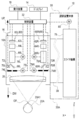
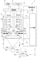
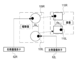
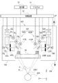
- the surgical microscope main body 16 includes an optical system 60.
- the optical system 60 includes an objective lens 26, a right side illumination optical system 60R, and a left side illumination optical system 60L.
- the optical system 60 is a Galileo type observation optical system. Therefore, in the optical system 60, the objective lens 26 is shared by the right side illumination optical system 60R and the left side illumination optical system 60L.
- the Galileo-type observation optical system is illustrated, but the technique of the present disclosure is not limited to this, and for example, a Greenough-type observation optical system or a pupil division-type observation optical system is used. Is also possible.
- the right side illumination optical system 60R includes a right side imaging element 62R, a right side imaging optical system 64R, a right side magnification optical system 66R, a right side deflection element 68R, a right side light source 70R, a right side illumination optical system 72R, and a right side diaphragm 74R.
- the right diaphragm 74R is a movable diaphragm, and is mechanically connected to the drive shaft of the right diaphragm driving motor 78R.
- the right diaphragm drive motor 78R is electrically connected to the control device 32 and operates under the control of the control device 32.
- the right diaphragm 74R is opened and closed by the power of the right diaphragm driving motor 78R being applied in accordance with the instruction from the control device 32. That is, the opening degree of the right-side throttle 74R is controlled by the control device 32.
- the right magnification varying optical system 66R includes a plurality of lenses including at least one magnification varying lens, and the magnification varying lens is mechanically connected to the drive shaft of the right magnification varying motor 76R. There is.
- the right scaling motor 76R is electrically connected to the control device 32 and operates under the control of the control device 32.
- the variable power lens of the right variable power optical system 66R moves along the optical axis direction of the right variable power optical system 66R when the power of the right variable power motor 76R is applied according to an instruction from the control device 32. That is, the position of the variable power lens of the right variable power optical system 66R is controlled by the controller 32.
- Right side light source 70R emits right side illumination light, which is light for right side observation, toward right side illumination optical system 72R.
- the right side illumination optical system 72R is an optical system including at least one lens, and transmits the right side illumination light emitted as the illumination light from the right side light source 70R and guides it to the right side deflection element 68R.
- the right deflection element 68R reflects the right illumination light guided by the right illumination optical system 72R toward the right movable diaphragm 74R.
- the right-side deflection element 68R may be, for example, a transflective element that transmits the right-side illumination light and reflects the right-side operative field light.
- the transflective element include a half mirror, a beam splitter, and a dichroic mirror.
- the right illumination light passes through the right diaphragm 74R, is refracted by the objective lens 26, and enters the eye portion 20A.
- the right side illumination light is obliquely incident on the cornea 20A1 of the eye portion 20A from the positive side of the X axis to the negative side of the X axis.
- the light obtained by the right side illumination light being reflected by the eye portion 20A is incident on the right side deflecting element 68R as the above-mentioned right side surgical field light by tracing back the optical path coaxial with the right side illumination light.
- Lights of a plurality of wavelengths including right surgical field light are incident on the right deflection element 68R.
- the right-side deflection element 68R transmits the right-side surgical field light of the plurality of incident wavelength light beams to deflect the right-side surgical field light to the right-side variable magnification optical system 66R.
- Right-side surgical field light deflected by the right-side deflecting element 68R is incident on the right-side variable magnification optical system 66R.
- the right variable power optical system 66R changes the right surgical field image shown by the incident right surgical field light.
- the right-side variable power optical system 66R transmits the incident right-side surgical field light and guides it to the right-side imaging optical system 62R.
- the right imaging optical system 64R is an optical system including at least one lens, takes in the right surgical field light guided by the right zoom optical system 66R, and receives the captured right surgical field light of the right imaging element 62R. Form an image on the surface.
- a CMOS image sensor is used as the right image pickup element 62R.
- the right image pickup device 62R is an image pickup device in which a photoelectric conversion element, a signal processing circuit (for example, LSI), and a memory (for example, DRAM or SRAM) are integrated into one chip.
- a laminated image sensor can be cited.
- a signal processing circuit and a memory are laminated on a photoelectric conversion element.
- the right image pickup device 62R is not limited to the CMOS image sensor, but may be a CCD image sensor, for example.
- the right imaging element 62R images the operative field 28 (see FIG. 1) at a specific frame rate (for example, 60 fps (frames per second)) based on the right operative field light imaged on the light receiving surface.
- a specific frame rate for example, 60 fps (frames per second)
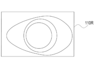
- the right image 110R showing the operative field 28 is generated by the right image sensor 62R, and the generated right image 110R is output to the control device 32 as a moving image by the right image sensor 62R.
- the left side illumination optical system 60L includes a left side imaging element 62L, a left side imaging optical system 64L, a left side variable magnification optical system 66L, a left side deflection element 68L, a left side light source 70L, a left side illumination optical system 72L, and a left side diaphragm 74L.
- the left diaphragm 74L is a movable diaphragm, and is mechanically connected to the drive shaft of the left diaphragm driving motor 78L.
- the left diaphragm drive motor 78L is electrically connected to the control device 32 and operates under the control of the control device 32.
- the left diaphragm 74L opens and closes when the power of the left diaphragm driving motor 78L is applied according to an instruction from the control device 32. That is, the opening degree of the left throttle 74L is controlled by the control device 32.
- the left-side variable power optical system 66L includes a plurality of lenses including at least one variable-power lens, and the variable-power lens is mechanically connected to the drive shaft of the left-side variable-power motor 76L. There is.
- the left scaling motor 76L is electrically connected to the control device 32 and operates under the control of the control device 32.
- the variable power lens of the left variable power optical system 66L moves along the optical axis direction of the left variable power optical system 66L when the power of the left variable power motor 76L is applied according to the instruction of the control device 32. That is, the position of the variable power lens of the left variable power optical system 66L is controlled by the controller 32.
- the left-side light source 70L emits left-side illumination light, which is light for left-side observation, toward the left-side illumination optical system 72L.
- the left side illumination optical system 72L is an optical system including at least one lens, and transmits the left side illumination light emitted as the illumination light from the left side light source 70L and guides it to the left side deflection element 68L.
- the left deflection element 68L reflects the left illumination light guided by the left illumination optical system 72L toward the left movable diaphragm 74L.
- the left-side deflecting element 68L may be, for example, a transflective element that transmits the left-side illumination light and reflects the left-side surgical field light.
- the transflective element include a half mirror, a beam splitter, and a dichroic mirror.
- the left illumination light passes through the left diaphragm 74L, is refracted by the objective lens 26, and enters the eye 20A.
- the left side illumination light is obliquely incident on the cornea 20A1 of the eye portion 20A from the negative side of the X axis to the positive side of the X axis.
- the light obtained by the left side illumination light being reflected by the eye portion 20A goes back to the left side deflection element 68R as the above-mentioned left side operative field light by tracing back the optical path coaxial with the observation light.
- a plurality of wavelengths of light including the left operative field light is incident on the left deflection element 68L.
- the left-side deflecting element 68L transmits the left-side surgical field light of the plurality of incident wavelength lights to deflect the left-side surgical field light to the left-side variable power optical system 66L.
- the left operative field light deflected by the left deflecting element 68L is incident on the left variable power optical system 66L.
- the left zoom optical system 66L zooms the left surgical field image indicated by the incident left surgical field light.
- the left zoom optical system 66L transmits the incident left surgical field light and guides it to the left imaging optical system 64L.
- the left imaging optical system 64L is an optical system including at least one lens, takes in the left surgical field light guided by the left zoom optical system 66L, and receives the captured left surgical field light of the left imaging element 62L. Form an image on the surface.
- the left image pickup device 62L is an image pickup device having the same structure as the right image pickup device 62R.
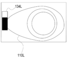
- the left imaging element 62L images the surgical field 28 (see FIG. 1) at the same frame rate as the right imaging element 62R based on the left surgical field light imaged on the light receiving surface. Accordingly, the left image 110L (see FIG. 7) showing the operative field 28 is generated by the left image sensor 62L, and the generated left image 110L is output to the control device 32 as a moving image by the left image sensor 62L.
- the adjusting device main body 30 includes a slide mechanism 78 in the housing 30A.
- One end of the support arm 38 is fixed to the slide mechanism 78.
- the slide mechanism 78 is mechanically connected to the drive shaft of the focus position adjusting motor 80.
- the focus position adjusting motor 80 is electrically connected to the control device 32 and is controlled by the control device 32.
- Examples of the slide mechanism 78 include a rack and pinion, a crank mechanism, and/or a ball screw mechanism.
- the slide mechanism 78 moves the surgical microscope main body 16 along the vertical direction via the support arm 38 when the power of the focusing position adjusting motor 80 is applied according to the instruction of the control device 32. That is, the slide mechanism 78 receives the power from the focusing position adjusting motor 80 under the control of the control device 32, and selects the entire optical system 60 together with the housing 16A in the vertically upward direction UP and the vertically downward direction DW. Move it.
- the focus position GP on the object point side of the optical system 60 (hereinafter, simply referred to as “focus position GP”) is located closer to the objective lens 26 than the cornea 20A1.
- the control device 32 operates the slide mechanism 78 to move the surgical microscope body 16 in a predetermined moving direction (for example, the vertical downward direction DW, one direction, and a linear direction), and thereby the focus position GP. Can be fitted to the cornea 20A1.
- the focus position is adjusted by moving the surgical microscope body 16, but the technique of the present disclosure is not limited to this.
- a focus lens may be incorporated in the optical system 60, and the focus position may be adjusted by moving the focus lens.
- the in-focus position GP refers to the position where the focus is achieved.
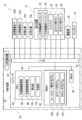
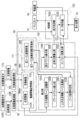
- FIG. 5 is a block diagram showing the configuration of the electric system of the surgery support system 10.
- the control device 32 includes a computer 82 and a secondary storage device 83.
- the computer 82 includes a CPU 84, a ROM 86, a RAM 88, and an I/O (input/output interface) 90.
- the CPU 84, ROM 86, and RAM 88 are connected to the bus line 92.
- the bus line 92 is connected to the I/O 90.
- the secondary storage device 83 is also connected to the I/O 90.
- the CPU 84 exchanges information with the ROM 86, the RAM 88, and the secondary storage device 83.
- the CPU 90 centrally controls the entire surgery support system 10.
- the ROM 86 is a memory that stores a program for controlling the basic operation of the surgery support system 10, various parameters, and the like.
- the RAM 88 is a volatile memory used as a work area or the like when executing various programs.
- the secondary storage device 83 is a non-volatile memory that stores a program different from the program stored in the ROM 86 and/or various parameters different from the various parameters stored in the various parameter ROM 86. Examples of the secondary storage device 83 include a HDD, an EEPROM, and/or a flash memory.
- a plurality of external devices are connected to the I/O 90.
- the plurality of external devices connected to the I/O 90 are the right image pickup device 62R, the left image pickup device 62L, the right light source 70R, the left light source 70L, the reception device 19, the drive source 94, and the display 14. It is shown.
- the reception device 19 is a device that receives an instruction from the user 24, and includes an upward movement foot switch 46, a downward movement foot switch 48, a touch pad 40, a left click button 42, and a right click button 44. ..
- the drive source 94 is a plurality of drive devices that generate power for moving mechanical parts, and includes a right-side aperture driving motor 78R, a left-side aperture driving motor 78L, a right-side scaling motor 76R, and a left-side scaling motor 76L. , And a focusing position adjusting motor 80 and the like.
- the right side image pickup device 62R, the left side image pickup device 62L, the right side light source 70R, the left side light source 70L, the reception device 19, the drive source 94, and the display 14 are controlled by the CPU 84, respectively.
- ROM86 stores a focus system program.
- the “focus system program” mentioned here refers to the focus mode setting program 104, the AF mode program 106, and the MF mode program 108.
- the CPU 84 reads the focus system program from the ROM 86 and expands the read focus system program in the RAM 88. Then, the CPU 84 operates as the right side image acquisition unit 96, the left side image acquisition unit 98, the derivation unit 100, and the control unit 102 by executing the focus system program expanded in the RAM 88.
- the operating microscope 12 has an AF mode and an MF mode as operation modes for adjusting the focus position.
- the AF mode and the MF mode are selectively set in the surgical microscope 12.
- FIG. 6 shows a mode of the focus adjustment screen 14B displayed on the display 14 when the focus mode setting program 104 is executed by the CPU 84.
- An observation start button 14C, a menu window 14D, and an arrow pointer 14E are displayed on the focus adjustment screen 14B.
- the display modes of the observation start button 14C, the menu window 14D, and the arrow pointer 14E change based on the instruction received by the reception device 19.
- the arrow pointer 14E moves within the focus adjustment screen 14B based on the instruction received by the touchpad 40.
- the observation start button 14C is turned on.
- imaging of the observation target for example, the operative field 28
- the right imaging element 62R and the left imaging element 62L is started.
- the operative field 28 (see FIG. 1) is imaged by the right imaging element 62R, a right image 110R is obtained and generated as shown in FIG.
- the operative field 28 see FIG. 1
- the left imaging element 62L a left image 110L is obtained and generated as shown in FIG.
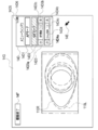
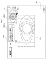
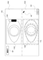
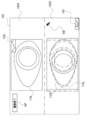
- the screen of the display 14 is switched from the focus adjustment screen 14B to the observation screen 14G under the control of the CPU 84, as shown in FIG.
- the observation screen 14G is different from the focus adjustment screen 14B in that an observation end button 14F is displayed instead of the observation start button 14C and a right side image 110R and a left side image 110L are displayed.
- the observation end button 14F is turned on when the observation of the surgical field 28 is finished.
- the method of turning on the observation end button 14F is the same as the method of turning on the observation start button 14C.
- the right-side image 110R and the left-side image 110L are displayed in a state of being overlapped with each other in an area of the observation screen 14G that does not overlap with the observation end button 14F and the menu window 14D.
- the stereoscopic image 112 based on the right image 110R and the left image 110L is the observation screen 14G. It is perceived by the user 24 at a position protruding from. This is because light showing the right side image 110R passes through the right eye lens 52R of the polarizing glasses 52 as the above right parallax image light 54R, and light showing the left side image 110L as the above left parallax image light 54L of the polarizing glasses 52. This is because the light passes through the left-eye lens 52L (see FIG. 3).
- an AF mode button 14D1 an MF mode button 14D2, an aperture opening change button 14D3, a zoom magnification change button 14D4, a minimize button 14D5, and a maximize button 14D6 are provided. It is displayed.
- the method of turning on the various buttons in the menu window 14D is the same as the method of turning on the observation start button 14C. That is, when the arrow pointer 14E is operated by the user 24, various buttons in the menu window 14D are turned on.
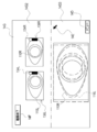
- the AF mode button 14D1 is turned on when the operation mode of the surgical microscope 12 is set to the AF mode
- the MF mode button 14D2 is turned on when the operation mode of the surgical microscope 12 is set to the MF mode.
- the AF mode button 14D1 when the AF mode button 14D1 is turned on, under the control of the CPU 84, the AF mode button 14D1 is highlighted and the MF mode button 14D2 is highlighted as shown in FIG.
- the aperture opening change button 14D3 is a button operated when changing the opening of both the right aperture 74R and the left aperture 74L (hereinafter, simply referred to as "aperture aperture”).
- the aperture opening change button 14D3 has an opening “small” button 14D3a, an opening “large” button 14D3b, and an opening display column 14D3c.
- the opening degree display field 14D3c a numerical value indicating the current throttle opening degree is displayed under the control of the CPU 84.
- the opening "small” button 14D3a is turned on, the aperture opening is reduced under the control of the CPU 84, and when the opening "large” button 14D3b is turned on, the aperture opening is increased under the control of the CPU 84.
- the numerical value of the aperture display field 14D3c is updated according to the change of the aperture opening under the control of the CPU 84.
- the zoom magnification change button 14D4 is a button operated when changing the zoom magnification (hereinafter, simply referred to as “zoom magnification”) by both the right variable magnification optical system 66R and the left variable magnification optical system 66L.
- the zoom magnification change button 14D4 has a zoom magnification “small” button 14D4a, a zoom magnification “large” button 14D4b, and a zoom magnification display field 14D4c. Under the control of the CPU 84, a numerical value indicating the current zoom magnification is displayed in the zoom magnification display field 14D3c.
- the zoom magnification “small” button 14D4a When the zoom magnification “small” button 14D4a is turned on, the zoom magnification is reduced under the control of the CPU 84, and when the zoom magnification “large” button 14D4b is turned on, the zoom magnification is increased under the control of the CPU 84.
- the zoom magnification is changed in this way, the value of the zoom magnification display field 14D4c is updated according to the change of the zoom magnification under the control of the CPU 84.
- the minimize button 14D5 is a button operated when the menu window 14D is minimized.
- the maximize button 14D6 is a button operated when maximizing the menu window 14D. In the example shown in FIG. 8, the menu window 14D is maximized.
- the maximize button 14D6 is turned on while the menu window 14D is maximized, the size of the menu window 14D can be changed using the arrow pointer 14E.
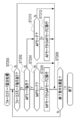
- FIG. 11 is a functional block diagram showing the functions of the surgical microscope 12 when the operation mode of the surgical microscope 12 is the AF mode.
- the right-side image acquisition unit 96 acquires from the right-side image sensor 62R a right-side image 110R obtained by capturing the operative field 28 (see FIG. 1) with the right-side image sensor 62R. Then, the right image acquisition unit 96 stores the right image 110R acquired from the right image sensor 62R in the captured image storage area 88A of the RAM 88.
- the left-side image acquisition unit 98 acquires the left-side image 110L obtained by capturing the operative field 28 (see FIG. 1) by the left-side image sensor 62L from the left-side image sensor 62L. Then, the left-side image acquisition unit 98 stores the left-side image 110L acquired from the left-side image sensor 62L in the captured-image storage area 88A of the RAM 88.
- the deriving unit 100 derives the correlation between the right-side image 110R and the left-side image 110L by the phase-only correlation method at a predetermined timing (for example, AF mode).
- the derivation unit 100 includes a two-dimensional discrete Fourier transform unit 100A, a power spectrum calculation unit 100B, a two-dimensional inverse discrete Fourier transform unit 100C, a peak coordinate identification unit 100D, a displacement vector calculation unit 100E, a focus position calculation unit 100F, and a contrast value. It has a calculation unit 100G.
- the two-dimensional discrete Fourier transform unit 100A performs a discrete Fourier transform on the right image 110R according to the following mathematical expression (1). Also, the two-dimensional discrete Fourier transform unit 100A performs a discrete Fourier transform on the left image 110L according to the following mathematical expression (2).
- the image 110FR is obtained by the function F(k 1 , k 2 ) as illustrated in FIG. 12A.
- the image 110FL is obtained by the function G(k 1 , k 2 ) as illustrated in FIG. 12B.
- f(n 1 , n 2 ) is a function indicating the right image 110R of N 1 ⁇ N 2 pixels
- g(n 1 , n 2 ) is N 1 It is a function showing the left image 110L of ⁇ N 2 pixels.
- M 1 and M 2 are positive integers
- a F (k 1 , k 2 ) and A G (k 1 , k 2 ) are amplitude spectra
- K 1 , k 2 ) is an amplitude spectrum.
- ⁇ n1, n2 included in the equations (1) and (2) are defined as follows.
- the power spectrum calculation unit 100B calculates the normalized mutual power spectrum R(k 1 , k 2 ) using the following mathematical expression (3) based on the conversion result of the two-dimensional discrete Fourier transform unit 100A.
- the two-dimensional inverse discrete Fourier transform unit 100C calculates the phase-only correlation function r(n 1 , n 2 ) as the two-dimensional inverse Fourier transform of the normalized mutual power spectrum by using the following mathematical expression (4).
- ⁇ k1, k2 included in the mathematical expression (4) is defined as follows.
- the phase-only correlation function r(n 1 , n 2 ) has an extremely sharp peak (correlation peak) rp close to a delta function as shown in FIG.
- the height of the correlation peak rp represents the linearity of the phase difference spectrum of the right-side image 110R and the left-side image 110L. If the phase difference spectrum is linear with respect to the frequency, the height of the correlation peak is 1.
- the height of the correlation peak is useful as a measure of the similarity between the right image 110R and the left image 110L.
- the coordinates of the correlation peak correspond to the relative positional deviation between the right side image 110R and the left side image 110L.
- Two-dimensional discrete Fourier transform is performed on the two images, the normalized mutual power spectrum is calculated based on the result of the two-dimensional discrete Fourier transform, and the normalized mutual power spectrum is two-dimensional inverse Fourier transformed to obtain the phase.
- the limited correlation function is calculated.
- a detailed calculation method for performing a two-dimensional inverse Fourier transform on the calculated normalized mutual power spectrum is disclosed in "http://www.aoki.ecei.tokyo.ac.jp/ ⁇ ito/vol_030.pdf" and the like. Has been done.
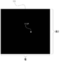
- FIG. 14 shows an inverse Fourier transform image 111, which is a two-dimensional image represented by the phase-only correlation function r(n1, n2) calculated by the two-dimensional inverse discrete Fourier transform unit 100C. That is, the inverse Fourier transform image 111 is an inverse Fourier transform image of the normalized mutual power spectrum.
- the correlation peak 111P appears at the position corresponding to the position of the correlation peak rp shown in FIG.
- the inverse Fourier transform image 111 is stored in the inverse Fourier transform image storage area 88B of the RAM 88 by the two-dimensional inverse discrete Fourier transform unit 100C.
- the peak coordinate specifying unit 100D specifies the coordinates of the correlation peak 111P (hereinafter, referred to as "peak coordinates") from the inverse Fourier transform image 111.
- the peak coordinates are coordinates indicating the position of the maximum pixel value in the inverse Fourier transform image 111. Therefore, as shown in FIG. 15, the peak coordinate specifying unit 100D extends from the origin (X 0 , Y 0 ) to the end point coordinates (X n , Y n ) along the direction of the broken line arrow in the inverse Fourier transform image 111.
- the pixel value for each pixel is acquired, and the coordinates indicating the position of the maximum pixel value are specified. In the example illustrated in FIG.
- the peak coordinate specifying unit 100D acquires pixel values pixel by pixel from the uppermost row to the lowermost row of the inverse Fourier transform image 111, updating the maximum pixel value and updating the maximum pixel value.
- the peak coordinates are specified by updating the coordinates indicating the position of the pixel value of.
- the displacement vector calculation unit 100E calculates the displacement vector based on the peak coordinates identified by the peak coordinate identification unit 100D.
- the “displacement vector” referred to here includes the displacement vector of one of the right image 110R and the left image 110L with respect to the other.
- the displacement vector calculation unit 110E calculates the displacement vector of the left image 110L with respect to the right image 110R.
- the displacement vector (d x , d y ) is the movement amount of Equation (2) with respect to f(n 1 , n 2 ) shown in Equation (1).
- ⁇ 1 refers to "(width-1)/2”
- ⁇ 2 refers to "(height-1)/2”.
- Width is the "width” shown in FIG. 15, and "height” is the “height” shown in FIG.
- the focus position calculation unit 100F calculates an adjustment amount dz required to adjust the focus position GP to a predetermined position by using the following mathematical expression (5) based on the displacement vector calculated by the displacement vector calculation unit 100E.
- the “predetermined position” mentioned here refers to an observation position (for example, the position of the apex of the cornea 20A1) described later.
- the “adjustment amount” referred to here is the shift from the observing position (for example, the current position that is out of focus (the position in the out-of-focus state)) to the focusing surface GG shown in FIG. It corresponds to the amount and includes the movement direction and movement amount of the surgical microscope body 16.
- the in-focus surface GG means a surface in focus.
- the focusing surface GG can also be called a “target surface” from the viewpoint of being a surface for autofocusing.
- the observation position is on the cornea 20A1 and the focusing surface GG is formed in the pupil of the eye 20A.
- the focusing surface GG is a focusing surface (target surface) that has the deepest depth of field for the entire operative field 28.
- the position of the focusing surface GG that is, the position of the pupil of the eye 20A is specified by performing image analysis of the right-side image 110R and/or the left-side image 110L by the focusing position calculation unit 100F.
- the following formula (5) is a formula having dx g , de, g as the independent variables and the adjustment amount dz as the dependent variable.
- g is the focusing distance from the objective lens 26 to the focusing surface GG
- de is the distance between the right deflection element 68R and the left deflection element 68L.
- dx g is the amount of deviation in the parallax generation direction on the focusing surface GG.
- dx p is a shift amount between the right side image 110R generated based on the right side surgical field image 109R and the left side image generated based on the left side surgical field image 109L.
- dx g is defined by the following mathematical expression (6). Equation (6) below has ⁇ ,dx i as the independent variable and dx g as the dependent variable. Further, as shown in the following mathematical expression (6), dx i is defined as the ratio of dx p to w p .
- dx i is a right operative field image 109R that is an observation image formed on the light receiving surface (image surface) of the right imaging element 62R and the light receiving surface (image surface) of the left imaging element 62L.
- ⁇ is a total zoom magnification of the optical system.
- the optical system total zoom magnification is a value calculated based on the zoom magnification set at the present time.
- w p is a width between pixels included in the right image pickup element 62R and the left image pickup element 62L, that is, a pitch between pixels.
- the contrast value calculation unit 100G calculates the contrast value of each of the right side image 110R and the left side image 110L. Further, the contrast value calculation unit 100G calculates an arithmetic mean value of the contrast value of the right image 110R and the contrast value of the left image 110L.
- the contrast value calculated by the contrast value calculation unit 100G is mainly used by the motor control unit 102B as a contrast value used for so-called contrast AF. That is, the focus position adjusting motor 80 is controlled by the motor control unit 102B based on the contrast value calculated by the contrast value calculation unit 100G.
- the control unit 102 has a display control unit 102A and a motor control unit 102B.
- the display control unit 102A selectively displays the focus adjustment screen 14B (see FIG. 6) and the observation screen 14G (see FIG. 8) on the display 14.
- the display control unit 102A controls the display 14 to change the display mode of the focus adjustment screen 14B and the observation screen 14G according to the instruction received by the reception device 19.
- the display control unit 102A When displaying the observation screen 14G on the display 14, the display control unit 102A acquires the right side image 110R and the left side image 110L from the captured image storage area 88A at the display frame rate (for example, 60 fps). The display control unit 102A applies linearly polarized light orthogonal to each other to the acquired right image 110R and left image 110L. Then, the display control unit 102A superimposes the right-side image 110R and the left-side image 110L, which are linearly polarized, on the display 14 according to the display frame rate. As a result, as shown in FIG. 9, the stereoscopic image 112 is visually recognized by the user 24 as a live view image or a real-time image at a position protruding from the observation screen 14G.
- the display control unit 102A When displaying the observation screen 14G on the display 14, the display control unit 102A acquires the right side image 110R and the left side image 110L from the captured image storage area 88A at the
- the adjustment amount dz is output to the motor control unit 102B by the focus position calculation unit 100F at an output timing determined based on the display frame rate.
- the “output timing” mentioned here includes, for example, timing defined by a frame rate that is an even multiple of the display frame rate.
- the motor control unit 102B controls the focus position adjusting motor 80 (see FIG. 4) of the drive source 94 so that the focus position GP is adjusted based on the adjustment amount dz input from the focus position calculation unit 100F. To do. As a result, the slide mechanism 78 receives the power of the focusing position adjusting motor 80, so that the surgical microscope main body 16 is moved vertically downward DW so that the focusing position GP is aligned with the focusing surface GG (see FIG. 16). Move to.
- the motor control unit 102B adjusts the focus position adjustment motor 80 (of the drive source 94) so that the focus position GP is adjusted in real time (immediately). (See FIG. 4). Therefore, the right-side image 110R and the left-side image 110L are generated while making the in-focus position GP follow the in-focus surface GG, and the generated right-side image 110R and the left-side image 110L are overlaid and displayed by the live view method (see FIG. 10). ). Accordingly, the stereoscopic image 112 (see FIG. 9) in the focused state on the focusing surface GG is visually recognized by the user 24 as a live view image or a real-time image.
- the motor control unit 102B controls the right diaphragm driving motor 78R (see FIG. 4) and the left diaphragm driving motor 78L (see FIG. 4) so that the diaphragm opening is changed.
- the right diaphragm driving motor 78R (see FIG. 4) and the left diaphragm driving motor 78L are set so that the diaphragm opening becomes smaller than the current diaphragm opening. Controlled.
- the right diaphragm driving motor 78R and the left diaphragm driving motor 78L are controlled so that the diaphragm opening becomes larger than the current diaphragm opening.
- the motor control unit 102B controls the right scaling motor 76R (see FIG. 4) and the left scaling motor 76L (see FIG. 4) so that the zoom magnification is changed.
- the zoom magnification “small” button 14D4a is turned on
- the right scaling motor 76R and the left scaling motor 76L are controlled so that the zoom magnification becomes smaller than the current zoom magnification.
- the zoom magnification “large” button 14D4b is turned on, the right scaling motor 76R and the left scaling motor 76L are controlled so that the zoom magnification becomes larger than the current zoom magnification.
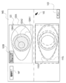
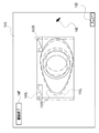
- the display control unit 102A displays the focus position designation guidance information 14G1.
- the focus position designation guidance information 14G1 is information having a guidance message 14G1a and a sample surgical field image 14G1b.
- the guidance message 14G1a and the sample surgical field image 14G1b are displayed adjacent to each other.
- a message “Please specify if there is an area to be focused on.” and an arrow pointing to the side of the sample surgical field image 14G1b are displayed.
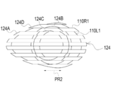
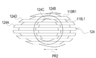
- a still image obtained by processing the right image 110R is displayed as the sample surgical field image 14G1b.
- the sample surgical field image 14G1b is a still image obtained by processing the right image 110R.
- an iris image region 15A showing the iris of the eye 20A
- a pupil peripheral image region 15B showing the peripheral part of the pupil of the eye 20A
- a pupil center image region showing the central part of the pupil of the eye 20A.
- 15C is highlighted in a distinguishable manner.
- the display control unit 102A When generating the sample surgical field image 14G1b, the display control unit 102A first acquires the right image 110R from the captured image storage area 88A. Next, the display control unit 102A performs image analysis on the acquired right image 110R, and specifies the iris image region 15A, the pupil peripheral image region 15B, and the pupil center image region 15C based on the result of the image analysis. Then, the display control unit 102A processes the identified iris image area 15A, pupil peripheral image area 15B, and pupil center image area 15C so as to distinguish the right image 110R from other image areas, and displays the image on the observation screen 14G. indicate.
- the display control unit 102A displays the lattice frame 15 over the sample surgical field image 14G1b as shown in FIG.
- the sample surgical field image 14G1b is displayed in a state of being divided into 15 regions by the lattice frame 15.
- the display control unit 102A contrasts the position specifying information for specifying the position of the specified divided area 17 on the sample surgical field image 14G1b.
- the user 24 In order for the user 24 to specify any one of the plurality of divided areas 17, the user 24 operates the touch pad 40 to indicate an arrow pointer to any one of the plurality of divided areas 17. 14E may be positioned and the left click button 42 may be turned on.
- the position specifying information refers to, for example, a unique identifier individually given to each of the plurality of divided areas 17. In the example shown in FIG. 19, since the sample surgical field image 14G1b is divided into 15, the divided regions 17 are given numbers (identifiers) “001 to 015”. When one of the plurality of divided areas 17 is designated by the arrow pointer 14E, the designated divided area 17 is specified from the number given to the designated divided area 17.
- the display control unit 102A erases the grid frame 15 from the display area of the sample surgical field image 14G1b.
- the contrast value calculation unit 100G acquires the right image 110R and the left image 110L from the captured image storage area 88A in real time (immediately).
- the contrast value calculation unit 100G receives the position specifying information, and specifies the divided area 17 designated by the user 24 from the received position specifying information. Then, the contrast value calculation unit 100G calculates the contrast values of the right side designated image area and the left side designated image area of the acquired right side image 110R and left side image 110L, respectively.
- the “right-side designated image area” here refers to an image area corresponding to the divided area 17 (see FIG. 19) designated by the arrow pointer 14E in the right-side image 110R.
- the “left-side designated image area” refers to an image area corresponding to the divided area 17 (see FIG. 19) designated by the arrow pointer 14E in the left-side image 110L.
- the contrast value calculation unit 100G calculates an average value of the contrast value of the right-side designated image area and the contrast value of the left-side designated image area.
- the contrast value calculation unit 100G outputs the calculated addition average value to the motor control unit 102B.
- the motor control unit 102B executes the contrast AF of the AF process based on the addition average value input from the contrast value calculation unit 100G, so that the real space region corresponding to the designated divided region 17 becomes the focused state. Adjust the focus position so that For example, the motor control unit 102B controls the focus position adjustment motor 80 (or the slide mechanism 78) so that the focus position is adjusted to the position where the arithmetic mean value calculated by the contrast value calculation unit 100G is the maximum. As a result, the position of the surgical microscope main body 16 is adjusted along the vertical direction (Z direction shown in FIGS. 1 to 4 and 16).
- the CPU 84 causes the MF mode for the surgical microscope 12 with respect to the surgical microscope 12. The mode is set.
- the MF mode button 14D2 is highlighted and the AF mode button 14D1 is highlighted as shown in FIG.
- the menu window 14D in the MF mode is different from that in the AF mode in that the menu window 14D further includes a focus support instruction receiving unit 21.
- the focus support instruction receiving unit 21 is a set of soft keys, and receives an instruction to display the focus support information on the observation screen 14G to the display control unit 102A.
- the focus support information is information for supporting the MF (Manual Focus) adjustment work by the user 24, and is roughly classified into first to sixth focus support information described below.
- the focus support information is an example of “indication information” according to the technology of the present disclosure, and the indication information refers to adjustment of the in-focus position by the adjustment device 18 in order to adjust the in-focus position to the designated area of the operative field 28.
- the suggestion information includes information that allows the adjustment state of the focus position to be visually recognized.
- the suggestion information is an adjustment state of the in-focus position (for example, in-focus state in focus, out-of-focus state out of focus, and/or how much the focus shifts in the out-of-focus state. It includes information that visually assists the adjustment of the in-focus position.
- the suggestion information includes information that visually guides the adjustment of the focus position by the user 24.
- the content of the instruction includes, for example, information corresponding to the adjustment amount in the present embodiment.
- the focus assistance instruction receiving unit 21 includes a first focus assistance information button 21A, a second focus assistance information button 21B, a third focus assistance information button 21C, a fourth focus assistance information button 21D, a fifth focus assistance information button 21E, and a fifth focus assistance information button 21E. It has 6 focus support information buttons 21F. Note that, for convenience of description, the first focus support information button 21A, the second focus support information button 21B, the third focus support information button 21C, the fourth focus support information button 21D, the fifth focus support information button 21E, and the fourth focus support information button 21E. When it is not necessary to distinguish and explain the 6 focus support information buttons 21F, they are referred to as "focus support information buttons" without reference numerals.
- the method for turning on the focus support information button is the same as the method for turning on the observation start button 14C.
- the control unit 102 When the operation mode of the surgical microscope 12 is the MF mode, the control unit 102 has a display control unit 102A, a motor control unit 102B, and a focus support information control unit 102C, as shown in FIG.
- the focus support information generation unit 102C acquires the right image 110R from the captured image storage area 88A, and based on the right image 110R, the first focus support information 120 (FIG. 22). Reference) is generated.
- the focus support information generation unit 102C outputs the generated first focus support information 120 to the display control unit 102A.
- the display control unit 102A outputs the first focus support information 120 input from the focus support information generation unit 102C to the display 14 to display it in the upper half display area of the observation screen 14G as illustrated in FIG.
- the display control unit 102A displays the right-side image 110R and the left-side image 110L in the live view mode by superimposing the right-side image 110R and the left-side image 110L on the lower half display area of the observation screen 14G.
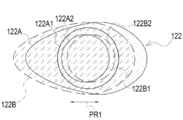
- the first focus support information 120 is information including a sample surgical field image 120A and a guidance message 120B.
- the sample surgical field image 120A is an image corresponding to an image obtained by enlarging the sample surgical field image 14G1b (see FIG. 18).
- the sample surgical field image 120A is a still image obtained by processing the right image 110R.
- the technique of the present disclosure is not limited thereto, and for example, the still image in which the left image 110L is processed is illustrated. May be used. Alternatively, the still image obtained by processing the right image 110R and the still image obtained by processing the left image 110L may be used together.
- the sample surgical field image 120A is highlighted so that the iris image area 120A1, the pupil periphery image area 120A2, and the pupil center image area 120A3 can be distinguished and recognized.
- the iris image area 120A1 is an image area corresponding to the iris image area 15A shown in FIG.
- the pupil peripheral image area 120A2 is an image area corresponding to the pupil peripheral image area 15B shown in FIG.
- the pupil center image area 120A3 is an image area corresponding to the pupil center image area 15C shown in FIG.
- the guidance message 120B is a message (an example of “indication information” according to the technology of the present disclosure) that indicates to the user 24 that the highlighted region in the sample surgical field image 120A is a candidate for the focused region.
- the message “The highlighted area is a focus area candidate” is displayed in an area that does not overlap the iris image area 120A1, the pupil peripheral image area 120A2, and the pupil center image area 120A3. ing.
- MF adjustment work is performed by operating the reception device 19 (focus operation unit) including the.
- the MF adjustment work includes, for example, operating the foot switch and inputting the MF operation by the user 24.
- the motor control unit 102B controls the focusing position adjusting motor 80 according to the operation of the foot switch by the user 24. That is, the motor control unit 102B moves the surgical microscope main body 16 in the vertical upward direction UP (see FIG. 4) by a movement amount corresponding to the stroke amount of the depression with respect to the upward movement foot switch 46.
- the motor control unit 102B moves the surgical microscope main body 16 in the vertical downward direction DW (see FIG. 4) by an amount of movement corresponding to the stroke amount of the depression with respect to the downward movement foot switch 48.
- the “movement amount according to the stroke amount” here means that, for example, the movement amount of the surgical microscope main body 16 increases as the stroke amount increases.
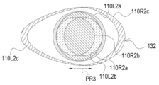
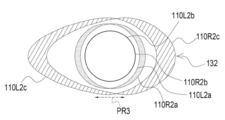
- the focus support information generation unit 102C When the second focus support information button 21B is turned on, the focus support information generation unit 102C generates the alpha blend image 122 (see FIG. 23) as the second focus support information.
- Alpha blending refers to a process of combining two images with a coefficient ( ⁇ value).
- ⁇ value a coefficient
- alpha blending a process of displaying a mask image in which a transparent portion is defined and transmitting an image designated as a transparent image to the transparent portion defined in the mask image Is mentioned.
- the focus support information generation unit 102C acquires the right side image 110R and the left side image 110L from the captured image storage area 88A in real time (immediately).
- the focus support information generation unit 102C acquires the right-side image 110R and the left-side image 110L, the right-side translucent image 122A (see FIG. 23), which is the translucent image of the right-side image 110R, and the left side, which is the translucent image of the left-side image 110L.
- the semi-transparent image 122B (see FIG. 23) is generated in real time (immediately). Then, the focus support information generation unit 102C generates the alpha blended image 122 in which the right-side semi-transparent image 122A and the left-side semi-transparent image 122B are overlapped, and outputs the generated alpha blended image 122 to the display control unit 102A.
- the display control unit 102A outputs the alpha blended image 122 input from the focus support information generation unit 102C to the display 14, and the live view method is used to display the alpha blended image 122 in the upper half display area of the observation screen 14G as illustrated in FIG. Let That is, the display control unit 102A performs control for updating the alpha blended image 122 in real time in synchronization with the adjustment by the adjustment device 18. In addition, as shown in FIG. 23, the display control unit 102A superimposes the right image 110R and the left image 110L on the lower half display area of the observation screen 14G and displays them in a live view manner.
- the MF adjustment operation is performed by operating the reference numerals 46 and 48 shown in FIG.
- the parallax generation direction PR1 is a direction including the parallax generation direction between the right-side semi-transparent image 122A and the left-side semi-transparent image 122B.
- the right-side semi-transparent image 122A has an iris outer edge 122A1 which is an outer edge of an iris image area showing an iris and a pupil outer edge 122A2 which is an outer edge of a pupil image area showing a pupil.
- the left-side semi-transparent image 122B has an iris outer edge 122B1 which is an outer edge of an iris image area showing an iris and a pupil outer edge 122B2 which is an outer edge of a pupil image area showing a pupil.
- the iris outer edge 122A1 and the iris outer edge 122B1 do not overlap. Further, the pupil outer edge 122A2 and the pupil outer edge 122B2 do not overlap. This means that the outer edge of the iris of the eye 20A is out of focus, and the outer edge of the pupil of the eye 20A is out of focus.
- the pupil outer edge 122A2 and the pupil outer edge 122B2 do not overlap, but the iris outer edge 122A1 and the iris outer edge 122B1 overlap. This means that the outer edge of the pupil of the eye 20A is out of focus and the outer edge of the iris of the eye 20A is in focus.
- the iris outer edge 122A1 and the iris outer edge 122B1 do not overlap, but the pupil outer edge 122A2 and the pupil outer edge 122B2 overlap. This means that the outer edge of the iris of the eye 20A is out of focus and the outer edge of the pupil of the eye 20A is in focus.
- the focus support information generation unit 102C generates the split image 124 (see FIG. 25) as the third focus support information.
- the split image 124 is a divided image (for example, each image divided in the vertical direction) into which the display area is divided, and is shifted in the parallax generation direction (for example, the horizontal direction) according to the focus shift, and the focus is adjusted. In the closed state, it means a divided image in which there is no deviation in the direction of parallax generation.
- the right-side divided image 110R1 and the left-side divided image 110L1 are alternately combined in the direction intersecting the parallax generation direction PR2 (in the example shown in FIG. 25, the vertical direction in the front view). It is an image of multiple divisions (13 divisions in the example shown in FIG. 25).
- the direction intersecting with the parallax generation direction PR2 is an example of the “specific direction” according to the technique of the present disclosure.
- the right divided image 110R1 is an image obtained by dividing the right image 110R in a direction intersecting the parallax generation direction PR2.
- the left side divided image 110L1 is an image obtained by dividing the left side image 110L in a direction intersecting with the parallax generation direction PR2.
- the right divided image 110R1 included in the split image 124 is displaced in a predetermined direction (parallax generation direction PR2 (horizontal direction in front view in the figure) in the example shown in FIG. 24) according to the focused state.
- the split image 124 includes an iris outer edge 124B that is an outer edge of an iris image region that indicates an iris, a pupil outer edge 124C that is an outer edge of a pupil image region that indicates a pupil, and an eye region that indicates the eye part 20A. And an eye outer edge 124D that is the outer edge of the.
- the outer contour 124A of the split image 124 on the parallax generation direction PR2 side is highlighted.
- the “outer contour 124 ⁇ /b>A” mentioned here refers to the outer contour of a characteristic region included in the split image 124. Examples of the outer contour of the characteristic region include the iris outer edge 124B, the pupil outer edge 124C, and the eye outer edge 124D.
- the "highlighted display” referred to here means a display in a mode in which the outer contour 124A is framed.
- the highlighting of the outer contour 124A is an example of “first highlighting” according to the technique of the present disclosure.
- the focus support information generation unit 102C acquires the right image 110R and the left image 110L from the captured image storage area 88A in real time (immediately).
- the focus support information generation unit 102C acquires the right side image 110R and the left side image 110L
- the focus support information generation unit 102C generates the split image 124 in real time (immediately) based on the acquired right side image 110R and left side image 110L. Then, the focus support information generation unit 102C outputs the generated split image 124 to the display control unit 102A.
- the display control unit 102A outputs the split image 124 input from the focus support information generation unit 102C to the display 14 and causes the display 14 to display the split image 124 in the upper half display area of the observation screen 14G by the live view method. .. That is, the display control unit 102A performs control for updating the split image 124 in real time in synchronization with the adjustment by the adjustment device 18. Further, as shown in FIG. 25, the display control unit 102A superimposes the right image 110R and the left image 110L on the lower half display area of the observation screen 14G and displays them in a live view manner.
- the user 24 visually recognizes the split image 124 and the stereoscopic image 112 shown in FIG. 9 while viewing the foot switch (FIG. 1 and FIG.
- the MF adjustment operation is performed by operating the reference numerals 46 and 48 shown in FIG.
- the right-side divided image 110R1 and the left-side divided image 110L1 included in the split image 124 are relatively moved along the parallax generation direction PR2. Gradually move to.
- the iris outer edge 124B is displaced in the parallax generation direction PR2. Further, the pupil outer edge 124C is also displaced in the parallax generation direction PR2. This means that the outer edge of the iris of the eye 20A is out of focus, and the outer edge of the pupil of the eye 20A is out of focus.
- the pupil outer edge 124C is shifted in the parallax generation direction PR2, but the iris outer edge 124B is a continuous line, and the shift of the iris outer edge 124B in the parallax generation direction PR2 is eliminated.
- the iris outer edge 124B is displaced in the parallax generation direction PR2, but the pupil outer edge 124C is a continuous line, and the deviation of the pupil outer edge 124C in the parallax generation direction PR2 is eliminated.
- the display control unit 102A changes the display screen as shown in FIG. Then, the guidance message 126 is displayed in the empty display area 14G0.
- the empty display area 14G0 is a display area different from the split image 124 and the observation end button 14F in the upper half display area of the observation screen 14G.
- the instruction to display the required movement amount information refers to an instruction to display the required movement amount information.
- the required movement amount information is the movement amount required to move the surgical microscope body 16 in the vertical direction (for example, the Z direction shown in FIG. 16) in order to bring the designated region of the eye 20A into the focused state (for example, This is information indicating the above-mentioned adjustment amount dz).
- the movement amount indicated by the required movement amount information is calculated by using the phase-only correlation method and the above-described equations (5) and (6).
- the required movement amount information includes upward movement required amount information 128 shown in FIG. 28 and downward movement required amount information 130 shown in FIG. 29.
- double-clicking the left click button 42 with the arrow pointer 14E positioned in the empty display area 14G0 is adopted.
- the guidance message 126 is a message that prompts the user 24 to specify a region to focus on by designating a partial region in the split image 124.
- a message “Please specify if there is an area to be focused on.” and an arrow pointing to the side of the split image 124 are illustrated.
- the user 24 positions the arrow pointer 14E in the area in the split image 124 where the user wants to focus and clicks the left click button 42.
- the display control unit 102A causes the display control unit 102A to display a predetermined portion of the empty area 14G0.
- the upward movement required amount information 128 is displayed on.
- the “predetermined location” mentioned here includes the area on the opposite side of the guide message 126 via the split image 124 in the empty area 14G0.
- the upward movement required amount information 128 shown in FIG. 28 is, for example, movement for moving the surgical microscope main body 16 in the vertical upward direction UP (see FIG. 4) in order to adjust the focus position to the designated area of the eye portion 20A. This is information indicating the amount.
- the “designated area of the eye 20A” referred to here corresponds to the area of the eye 20A designated by the arrow pointer 14E as the area to be focused (the iris outer edge 124B in the example shown in FIG. 28).
- the region (the outer edge of the iris of the eye 20A) is included.
- the upward movement required amount information 128 has an indicator 128A and an arrow 128B.
- the indicator 128A indicates the amount of movement of the surgical microscope main body 16 in the vertically upward direction UP from the start of displaying the split image 124 to the present time.
- the arrow 128B is displayed in the indicator 128A, and indicates the amount of movement in the vertically upward direction UP necessary for adjusting the focus position to the designated area of the eye 20A.
- the downward movement required amount information 130 shown in FIG. 29 is the movement amount for moving the surgical microscope main body 16 in the vertical downward direction DW (see FIG. 4) in order to adjust the focus position to the designated area of the eye portion 20A. It is information to show.
- the outer peripheral edge 124C of the pupil is designated by the arrow pointer 14E. Therefore, in the example shown in FIG. 29, the “designated area of the eye 20A” refers to the outer edge of the pupil of the eye 20A.
- the downward movement required amount information 130 has an indicator 130A and an arrow 130B.
- the indicator 130A indicates the amount of movement of the surgical microscope body 16 in the vertical downward direction DW from the start of displaying the split image 124 to the present time.
- the arrow 130B is displayed in the indicator 130A, and indicates the amount of movement in the vertically downward direction DW necessary for adjusting the focus position to the designated area of the eye 20A.
- the focus support information generation unit 102C when the fourth focus support information button 21D is turned on, the focus support information generation unit 102C generates a difference image 132 (see FIG. 30) as the fourth focus support information.
- the difference image 132 is an example of a “difference degree image” according to the technique of the present disclosure.
- the "difference degree image” referred to here is an image showing the degree of difference in pixel values at corresponding pixel positions between the right image 110R and the left image 110L.
- the degree of difference may be a subtraction value, a division value, an absolute value of the subtraction value, a combination of the subtraction value and the division value, a combination of the absolute value of the subtraction value and the division value, or a combination of addition and/or multiplication for these. Can be mentioned.
- the subtraction value is, for example, a subtraction value obtained by subtracting the pixel value of the corresponding pixel position included in the other from the pixel value of each pixel position of the right image 110R and the left image 110L.
- the division value refers to a division value obtained by dividing the pixel value of each pixel position of one of the right image 110R and the left image 110L by the pixel value of the corresponding pixel position included in the other.
- the focus support information generation unit 102C acquires the right image 110R and the left image 110L from the captured image storage area 88A in real time (immediately).
- the focus support information generation unit 102C calculates in real time (immediately) a difference value between corresponding pixel positions between the right image 110R and the left image 110L.
- the focus support information generation unit 102C generates the difference image 132 (see FIG. 30) by mapping the calculated difference value for each corresponding pixel position between the right image 110R and the left image 110L. Then, the focus support information generation unit 102C outputs the generated difference image 132 to the display control unit 102A.
- the display control unit 102A outputs the difference image 132 input from the focus support information generation unit 102C to the display 14, and causes the display 14 to display the difference image 132 in the upper half display area of the observation screen 14G by the live view method. .. That is, the display control unit 102A controls the difference image 132 to be updated in real time in synchronization with the adjustment by the adjustment device 18. Further, as shown in FIG. 30, the display control unit 102A displays the right-side image 110R and the left-side image 110L in the live view mode by superimposing the right-side image 110R and the left-side image 110L on the lower half display area of the observation screen 14G.
- the user 24 visually recognizes the differential image 132 and the stereoscopic image 112 shown in FIG. 9 while viewing the foot switch (FIG. 1 and FIG.
- the MF adjustment operation is performed by operating the reference numerals 46 and 48 shown in FIG.
- the distribution of difference values included in the difference image 132 is gradually displaced along the parallax generation direction PR3, as shown in FIGS. 30 and 31A to 31C.
- the parallax generation direction PR3 refers to the direction in which parallax occurs between the right contour image 110R2 and the left contour image 110L2.
- the right contour image 110R2 is an image formed by the outer contour of the characteristic region of the right image 110R.
- the right contour image 110R2 is a right iris outer edge 110R2a which is an outer edge of an iris image area showing an iris, a right pupil outer edge 110R2b which is an outer edge of a pupil image area showing a pupil, and an outer edge of an eye part area showing an eye part 20A. And a right eye outer edge 110R2c.
- the left-side contour image 110L2 is an image formed by the outer contour of the characteristic region of the left-side image 110L.
- the left-side contour image 110L2 is a left-side iris outer edge 110L2a that is the outer edge of the iris image area indicating the iris, a left-side pupil outer edge 110L2b that is the outer edge of the pupil image area indicating the pupil, and an outer edge of the eye area indicating the eye 20A. And a left eye outer edge 110L2c.
- the right iris outer edge 110R2a and the left iris outer edge 110L2a do not overlap.
- the right pupil outer edge 110R2b and the left pupil outer edge 110L2b do not overlap.
- the right eye outer edge 110R2c and the left eye outer edge 110L2c do not overlap. This means that the outer edge of the iris of the eye 20A is out of focus, the outer edge of the pupil of the eye 20A is out of focus, and the outer edge of the eye 20A is out of focus.
- the right pupil outer edge 110R2b and the left pupil outer edge 110L2b do not overlap.
- the right eye outer edge 110R2c and the left eye outer edge 110L2c also do not overlap.
- the right iris outer edge 110R2a and the left iris outer edge 110L2a overlap. This means that the outer edge of the pupil of the eye 20A and the outer edge of the eye 20A are out of focus, and the outer edge of the iris of the eye 20A is in focus.
- the right iris outer edge 110R2a and the left iris outer edge 110L2a do not overlap.
- the right eye outer edge 110R2c and the left eye outer edge 110L2c also do not overlap.
- the right pupil outer edge 110R2b and the left pupil outer edge 110L2b overlap. This means that the outer edge of the iris of the eye 20A and the outer edge of the eye 20A are out of focus, and the outer edge of the pupil of the eye 20A is in focus.
- the portion where the right iris outer edge 110R2a and the left iris outer edge 110L2a overlap is highlighted by the display control unit 102A.
- at least one of the right iris outer edge 110R2a and the left iris outer edge 110L2a is displayed in a bordered manner. This allows the user 24 to easily perceive that the region of the eye 20A that has reached the focused state is the outer edge of the iris.
- the display control unit 102A highlights the portion where the right pupil outer edge 110R2b and the left pupil outer edge 110L2b overlap. In this case, at least one of the right pupil outer edge 110R2b and the left pupil outer edge 110L2b is displayed in a framed manner. This allows the user 24 to easily perceive that the region of the eye 20A that has reached the focused state is the outer edge of the pupil.
- the highlighting of the portion where the right iris outer edge 110R2a and the left iris outer edge 110L2a overlap is an example of the second highlighting according to the technique of the present disclosure.
- highlighting of a portion where the right pupil outer edge 110R2b and the left pupil outer edge 110L2b overlap each other is also an example of second highlighting according to the technique of the present disclosure.
- the focus support information generation unit 102C When the fifth focus support information button 21E is turned on, the focus support information generation unit 102C generates a right contrast value indicator 134R and a left contrast value indicator 134L (see FIG. 32) as the fifth focus support information.
- the right contrast value indicator 134R is an indicator showing the contrast value of the right image 110R
- the left contrast value indicator 134L is an indicator showing the contrast value of the left image 110L.
- the focus support information generation unit 102C acquires the right image 110R and the left image 110L from the captured image storage area 88A in real time (immediately).
- the focus support information generation unit 102C acquires the right side image 110R and the left side image 110L, it calculates the contrast values of the acquired right side image 110R and left side image 110L in real time (immediately).
- the focus support information generation unit 102C generates the right contrast value indicator 134R based on the contrast value of the right image 110R, and generates the left contrast value indicator 134L based on the contrast value of the left image 110L. Then, the focus support information generation unit 102C outputs the generated right side contrast value indicator 134R and left side contrast value indicator 134L to the display control unit 102A.
- the display control unit 102A acquires the right image 110R and the left image 110L from the captured image storage area 88A in real time (immediately).
- the display control unit 102A applies linearly polarized light orthogonal to each other to the acquired right image 110R and left image 110L.
- the display control unit 102A superimposes the right-side image 110R and the left-side image 110L, which are linearly polarized, on each other and displays them on the observation screen 14G in accordance with the display frame rate.
- the display control unit 102A applies the same linear polarization as the right image 110R to the right contrast value indicator 134R input from the focus support information generation unit 102C.
- the display control unit 102A causes the right-side contrast value indicator 134R, which is linearly polarized, to be displayed on the display 14 by the live-view method along with the right-side image 110R according to the display frame rate, as shown in FIG. That is, the display control unit 102A causes the observation screen 14G to display the right contrast value indicator 134R and the right image 110R in association with each other.
- the display control unit 102A applies the same linear polarization as the left image 110L to the left contrast value indicator 134L input from the focus support information generation unit 102C. As shown in FIG. 32, the display control unit 102A causes the left-side contrast value indicator 134L, which is linearly polarized, to be displayed on the display 14 by the live-view method along with the left-side image 110L according to the display frame rate. That is, the display control unit 102A causes the observation screen 14G to display the left contrast value indicator 134L and the left image 110L in association with each other.
- the right-side image 110R and the right-side contrast value indicator 134R are displayed by the live view method, the right-side image 110R and the right-side contrast value indicator 134R pass through the right-eye lens 52R (see FIG. 3). Accordingly, as shown in FIG. 33A, the right image 110R and the right contrast value indicator 134R are visually recognized by the right eye of the user 24.
- the left side contrast value indicator 134L is displayed by the live view method together with the left side image 110L, the left side image 110L and the left side contrast value indicator 134L pass through the left eye lens 52L (see FIG. 3). Thereby, as shown in FIG. 33B, the left image 110L and the left contrast value indicator 134L are visually recognized by the left eye of the user 24.
- the right-side contrast value indicator 134R is linearly polarized like the right-side image 110R
- the left-side contrast value indicator 134L is linearly-polarized like the left-side image 110L. It is not limited to this. That is, the right contrast value indicator 134R and the left contrast value indicator 134L may be transmitted as the normal image light 58 (see FIG. 3) through the right eye lens 52R and the left eye lens 52L.
- the contrast value indicator 136 may be displayed on the observation screen 14G by the display control unit 102A.
- the contrast value indicator 136 is an indicator that shows an average value of the contrast value of the right side image 110R and the contrast value of the left side image 110L, and is generated by the focus support information generating unit 102C.
- the contrast value indicator 136 passes through the right-eye lens 52R and the left-eye lens 52L as normal image light 58.
- the technology of the present disclosure is not limited to this, and the contrast value of the right image 110R or the left image 110L may be applied instead of the addition average value.
- the display area of the upper half of the observation screen 14G is the contrast confirmation screen 14G2, and the lower half of the observation screen 14G is displayed.
- the area may be the stereoscopic image display screen 14G3.
- An image is displayed on the contrast confirmation screen 14G2 by the normal image light 58 (see FIG. 3) by the display control unit 102A.
- the right image 110R and the right contrast value indicator 134R are displayed by the display control unit 102A by the live view method.
- the right-side image 110R and the left-side image 110L which are linearly polarized, are superimposed and displayed according to the display frame rate.
- the technique of the present disclosure is not limited to this, and as shown in FIG. 36, the left side image 110R and the left side contrast value indicator 134L are displayed on the contrast confirmation screen 14G2 by the display control unit 102A in a live view system. It may be displayed. Also in this case, the right-side image 110R and the left-side image 110L, which are linearly polarized, are superimposed and displayed on the stereoscopic image display screen 14G3 in accordance with the display frame rate.
- the display control unit 102A displays the right side reference image 138R and the left image reference image 138L on the contrast confirmation screen 14G2 by the live view method. May be displayed in.
- the right reference image 138R is an image in a state where the right image 110R and the right contrast value indicator 134R are associated with each other.
- the left image reference image 138L is an image in a state where the left image 110L and the left contrast value indicator 134L are associated with each other.
- the focus support information generation unit 102C When the sixth focus support information button 21F is turned on, the focus support information generation unit 102C generates a right side contrast value graph 140R and a left side contrast value graph 140L (see FIG. 38) as the sixth focus support information.
- the right-side contrast value graph 140R is a graph showing the temporal change in the contrast value of the right-side image 110R
- the left-side contrast value graph 140L is a graph showing the temporal change in the contrast value of the left-side image 110L.
- the focus support information generation unit 102C acquires the right image 110R and the left image 110L from the captured image storage area 88A in real time (immediately).
- the focus support information generation unit 102C acquires the right side image 110R and the left side image 110L, it calculates the contrast values of the acquired right side image 110R and left side image 110L in real time (immediately).
- the focus support information generation unit 102C generates the right contrast value graph 140R based on the time series of the contrast values of the right image 110R, and generates the left contrast value graph 140L based on the time series of the contrast values of the left image 110L. Then, the focus support information generation unit 102C outputs the generated right side contrast value graph 140R and left side contrast value graph 140L to the display control unit 102A.
- the display control unit 102A acquires the right image 110R and the left image 110L from the captured image storage area 88A in real time (immediately).
- the display control unit 102A applies linearly polarized light orthogonal to each other to the acquired right image 110R and left image 110L.
- the display control unit 102A causes the right-side image 110R and the left-side image 110L, which are linearly polarized, to be superimposed and displayed on the observation screen 14G in accordance with the display frame rate.
- the display control unit 102A also applies the same linear polarization as the right image 110R to the right contrast value graph 140R input from the focus support information generation unit 102C. As shown in FIG. 38, the display control unit 102A displays the right-sided contrast value graph 140R, which is linearly polarized, together with the right-sided image 110R in the live view method according to the display frame rate. That is, the display control unit 102A displays the right contrast value graph 140R and the right image 110R on the observation screen 14G in a state of being associated with each other.
- the display control unit 102A applies the same linear polarization as the left image 110L to the left contrast value graph 140L input from the focus support information generation unit 102C. As shown in FIG. 38, the display control unit 102A causes the left-side contrast value graph 140L to which the linearly polarized light is applied to be displayed with the left-side image 110L in the live-view method according to the display frame rate. That is, the display control unit 102A displays the left-side contrast value graph 140L and the left-side image 110L in the associated state on the observation screen 14G.
- the right-side image 110R and the right-side contrast value graph 140R are displayed by the live view method
- the right-side image 110R and the right-side contrast value graph 140R pass through the right-eye lens 52R (see FIG. 3).
- the right image 110R and the right contrast value graph 140R are visually recognized by the right eye of the user 24.
- the left-side image 110L and the left-side contrast value graph 140L are displayed by the live view method
- the left-side image 110L and the left-side contrast value graph 140L are transmitted through the left-eye lens 52L (see FIG. 3).
- the left image 110L and the left contrast value graph 140L are visually recognized by the left eye of the user 24.
- the right-side contrast value graph 140R is linearly polarized like the right-side image 110R
- the left-side contrast value graph 140L is linearly-polarized like the left-side image 110L. It is not limited to this. That is, the right-side contrast value graph 140R and the left-side contrast value graph 140L may be transmitted as the normal image light 58 (see FIG. 3) through the right-eye lens 52R and the left-eye lens 52L.
- the contrast value graph 142 may be displayed on the observation screen 14G by the display control unit 102A.
- the contrast value graph 142 is a graph showing an arithmetic mean value of the right side contrast value graph 140R and the left side contrast value graph 140L, and is generated by the focus support information generation unit 102C.
- the contrast value graph 142 passes through the right-eye lens 52R and the left-eye lens 52L as the normal image light 58.
- the technology of the present disclosure is not limited to this, and the right side contrast value graph 140R or the left side contrast value graph 140L may be applied instead of the contrast value graph 142.
- the display area of the upper half of the observation screen 14G is the contrast change confirmation screen 14G4, and the lower half of the observation screen 14G is The display area may be the stereoscopic image display screen 14G5.
- An image is displayed on the contrast change confirmation screen 14G4 by the normal image light 58 (see FIG. 3) by the display control unit 102A.
- the right image 110R and the right contrast value graph 140R are displayed by the live view method by the display control unit 102A.
- the right-side image 110R and the left-side image 110L which are linearly polarized, are superimposed and displayed according to the display frame rate.
- the display control unit 102A displays the left side image 110R and the left side contrast value graph 140L on the contrast change confirmation screen 14G4 by the live view method. May be displayed in. Also in this case, the right-side image 110R and the left-side image 110L, which are linearly polarized, are superimposed and displayed on the stereoscopic image display screen 14G3 in accordance with the display frame rate.
- the technique of the present disclosure is not limited to this, and as shown in FIG. 43, the right side reference image 144R and the left image reference image 144L are live-viewed on the contrast change confirmation screen 14G4 by the display control unit 102A. You may make it display by a system.
- the right reference image 144R is an image in which the right image 110R and the right contrast value graph 140R are associated with each other.
- the left image reference image 144L is an image in which the left image 110L and the left contrast value graph 140L are associated with each other.
- the technology of the present disclosure is not limited to this.
- the focus position at the time when the specified contrast value is obtained is reproduced.
- the contrast value on the right contrast value graph 140R and the focus position information indicating the focus position corresponding thereto are stored in the RAM 88 in a state of being associated with each other.
- the user 24 operates the touch pad 40 to position the arrow pointer 14E on the right contrast value graph 140R.
- the motor control unit 102B displays focus position information corresponding to the contrast value of the portion of the right contrast value graph 140R where the arrow pointer 14E is located. It is acquired from the RAM 88.
- the motor control unit 102B controls the focusing position adjusting motor 80 so that the focusing position indicated by the focusing position information acquired from the RAM 88 is reproduced.
- the technology of the present disclosure is not limited to this.
- the above-described first to sixth focus support information may be displayed in a state of being arranged in the upper half display area of the observation screen 14G.
- a plurality of designated focus support information out of the first to sixth focus support information may be displayed side by side in the upper half display area of the observation screen 14G.
- FIG. 46 shows an example of the flow of focus mode setting processing executed by the CPU 84 in accordance with the focus mode setting program 104.
- step ST200 the CPU 84 determines whether or not there is a focus mode instruction. Whether or not there is a focus mode instruction is determined by whether or not the AF mode button 14D1 or the MF mode button 14D2 (see FIG. 6) is turned on. If there is no focus mode instruction in step ST200, the determination is negative, and the focus setting processing moves to step ST208. In step ST200, if there is a focus mode instruction, the determination is affirmative, and the focus mode setting process proceeds to step ST202.
- step ST202 the CPU 84 determines whether the focus mode instruction is the AF mode instruction. That is, in step ST202, it is determined whether or not the AF mode button 14D1 is turned on. If the focus mode instruction is the AF mode instruction in step ST202, the determination is affirmative, and the focus mode setting process proceeds to step ST204. If the focus mode instruction is the MF mode instruction in step ST202, the determination is negative, and the focus mode setting process proceeds to step ST210.
- the case where the focus mode instruction is the MF mode instruction means that the MF mode button 14D2 is turned on.
- step ST204 the CPU 84 determines whether the operation mode of the surgical microscope 12 is the MF mode. In step ST204, if the operation mode of the surgical microscope 12 is the MF mode, the determination is affirmative, and the focus mode setting process proceeds to step ST206. In step ST204, if the operation mode of the surgical microscope 12 is the AF mode, the determination is negative and the focus mode setting process proceeds to step ST208.
- step ST206 the CPU 84 shifts the operation mode of the surgical microscope 12 from the MF mode to the AF mode, and then the focus mode setting process shifts to step ST208.
- step ST210 the CPU 84 determines whether the operation mode of the surgical microscope 12 is the AF mode. In step ST210, if the operation mode of the surgical microscope 12 is the AF mode, the determination is affirmative, and the focus mode setting process proceeds to step ST212. In step ST210, when the operation mode of the surgical microscope 12 is the MF mode, the determination is negative, and the focus mode setting process proceeds to step ST208.
- step ST212 the CPU 84 shifts the operation mode of the surgical microscope 12 from the AF mode to the MF mode, and then the focus mode setting process shifts to step ST208.
- step ST208 the CPU 84 determines whether or not the condition for ending the focus mode setting process (focus mode setting process end condition) is satisfied.
- the focus mode setting process end condition include a condition that an instruction to end the focus mode setting process has been received by the reception device 19.
- step ST208 if the focus mode setting process termination condition is not satisfied, the determination is negative, and the focus mode setting process proceeds to step ST200.
- step ST208 if the focus mode setting process end condition is satisfied, the determination is affirmative and the focus mode setting process ends.
- FIG. 47 shows an example of the flow of AF mode processing executed by the CPU 84 in accordance with the AF mode program 106 when the operation mode of the surgical microscope 12 is the AF mode.
- step ST250 the CPU 84 causes the right imaging element 62R and the left imaging element 62L to image the operative field 28, and then the AF mode processing proceeds to step ST252.
- the right imaging element 62R images the operative field 28 to generate the right image 110R
- the left imaging element 62L images the operative field 28 to generate the left image 110L.
- step ST252 the CPU 84 acquires the right-side image 110R from the right-side image sensor 62R and the left-side image 110L from the left-side image sensor 62L, and then the AF mode process proceeds to step ST254.
- step ST254 the CPU 84 executes a two-dimensional discrete Fourier transform on each of the right side image 110R and the left side image 110L, and then the AF mode processing moves to step ST256.
- an image 110FR (see FIG. 12A) and an image 110FL (see FIG. 12B) are obtained.
- the image processing for removing the high frequency component may be performed on the image 110FR and the image 110FL.
- the removal of high frequency components is realized by using, for example, a low pass filter. As a result, since the noise component is removed, the calculation accuracy can be improved as compared with the case where the signal processing for removing the high frequency component is not performed.
- step ST256 CPU 84 calculates a normalized mutual power spectrum for image 110FR and image 110FL, and then the AF mode processing moves to step ST258.
- step ST258 the CPU 84 executes the two-dimensional inverse Fourier transform of the normalized mutual power spectrum to generate the inverse Fourier transform image 111, and then the AF mode processing shifts to step ST260.
- step ST260 the CPU 84 executes the peak coordinate identification processing shown in FIG. 48 as an example, and then the AF mode processing proceeds to step ST262.
- step ST260A the CPU 84 acquires the pixel value of the target pixel from the inverse Fourier transform image 111.
- step ST260B the CPU 84 determines whether the latest pixel value acquired in step ST260A among the pixel values acquired in step ST260A during the period from the start of the peak coordinate identification processing to the present time corresponds to the maximum pixel value. Determine whether or not.
- step ST260B when the latest pixel value does not correspond to the maximum pixel value, the determination is negative, and the peak coordinate identification processing moves to step ST260D.
- step ST260B if the latest pixel value corresponds to the maximum pixel value, the determination is affirmative, and the peak coordinate identification processing proceeds to step ST260C.
- step ST260C the CPU 84 updates the maximum pixel value and the peak coordinate. That is, the latest pixel value acquired in step ST260A is overwritten and saved in the RAM 88 as the maximum pixel value, and the coordinates of the pixel corresponding to the latest pixel value acquired in step ST260A is overwritten and saved in the RAM 88 as peak coordinates.
- step ST260D the CPU 84 determines whether or not the pixel values of all the pixels included in the inverse Fourier transform image 111 are acquired in step ST260A.
- step ST260D when the pixel values of all the pixels included in the inverse Fourier transform image 111 are not acquired in step ST260A, the determination is negative, and the peak coordinate identification processing proceeds to step ST260E.
- step ST260E the CPU 84 changes the target pixel to an unprocessed pixel, and then the peak coordinate specifying process proceeds to step ST260A.
- the “unprocessed pixel” refers to a pixel that is not the processing target in step ST260A.
- step ST260D when the pixel values of all the pixels included in the inverse Fourier transform image 111 are acquired in step ST260A, the determination is affirmative and the peak coordinate identification processing ends.
- step ST262 the CPU 84 calculates a displacement vector from the peak coordinates obtained by executing the peak coordinate identification processing, and then the AF mode processing proceeds to step ST264.
- step ST264 CPU 84 calculates the in-focus position based on the displacement vector calculated in step ST262, and then the AF mode processing moves to step ST266.
- the displacement vector and the like refer to various parameters included in the above-described mathematical expression (5) in addition to the displacement vector.
- step ST266 the CPU 84 adjusts the position of the surgical microscope main body 16 by controlling the focus position adjusting motor 80 so that the focus position calculated in step ST264 is reached, and then the AF mode processing is performed in step ST268. Move to.
- the focus position is automatically adjusted by performing AF using the phase-only correlation method. That is, in this step ST266, the CPU 84 automatically adjusts the focus position based on the above-described displacement vector and the like.
- step ST268 the CPU 84 determines whether or not the contrast AF execution condition is satisfied.
- the contrast AF execution condition means, for example, a condition that the divided area 17 shown in FIG. 19 is designated by the arrow pointer 14E.
- step ST268 if the contrast AF execution condition is not satisfied, the determination is negative, and the AF mode process proceeds to step ST260. If the contrast AF execution condition is satisfied in step ST268, the determination is affirmative and the AF mode process proceeds to step ST270.
- step ST270 the CPU 84 executes the contrast AF for the predetermined area of the operative field 28.
- the “predetermined area” mentioned here refers to a real space area corresponding to the designated divided area 17 (see FIG. 19) in the surgical field 28.
- the focus position is automatically adjusted by executing the contrast AF. That is, in this step ST266, the CPU 84 automatically adjusts the focus position based on the contrast value.
- the CPU 84 determines whether or not the condition for ending the AF mode process (AF mode process end condition) is satisfied.
- the AF mode processing end condition may be, for example, a condition that the MF mode button 14D2 is turned on.
- step ST272 if the AF mode processing end condition is not satisfied, the determination is negative and the AF mode processing moves to step ST250. In step ST272, when the AF mode processing end condition is satisfied, the determination is affirmative and the AF mode processing ends.
- FIG. 49 shows an example of the flow of MF mode processing executed by the CPU 84 in accordance with the MF mode program 108 when the operation mode of the surgical microscope 12 is the MF mode.
- step ST300 the CPU 84 controls the display 14 to start the display of the observation screen 14G and the stereoscopic live view image.
- the “stereoscopic live view image” mentioned here refers to the right-side image 110R and the left-side image 110L (see FIG. 18) stereoscopically viewed by the user 24 through the polarizing glasses 52 in the live-view method. That is, the right-side image 110R and the left-side image 110L, which are superimposed according to the display frame rate by applying mutually linearly polarized light, are stereoscopic live view images.
- the CPU 84 controls the display 14 to start displaying the focus support information described above.
- next step ST304 the CPU 84 determines whether or not the foot switch is turned on. If the foot switch is not turned on in step ST304, the determination is negative and the MF mode processing moves to step ST314. In step ST304, when the foot switch is turned on, the determination is affirmative, and the MF mode process proceeds to step ST306.
- step ST306 the CPU 84 controls the focusing position adjusting motor 80 to start the movement of the surgical microscope main body 16, and then the MF mode process proceeds to step ST308.
- step ST308 the CPU 84 updates the focus support information, and then the MF mode processing moves to step ST310.
- step ST310 the CPU 84 determines whether or not the foot switch has been turned off. When the foot switch is not turned off in step 310, the determination is negative, and the MF mode process proceeds to step ST308. If the foot switch is turned off in step 310, the determination is affirmative, and the MF mode processing moves to step ST312.
- step ST312 the CPU 84 stops the movement of the surgical microscope main body 16 by controlling the focusing position adjusting motor 80, and then the MF mode process proceeds to step ST314.
- step ST314 the CPU 84 determines whether or not the condition for ending the MF mode process (condition for ending the MF mode process) is satisfied.
- the condition for ending the MF mode process include a condition that the AF mode button 14D1 is turned on.
- step ST314 if the MF mode process end condition is not satisfied, the determination is negative and the MF mode process proceeds to step ST304.
- step ST314 when the MF mode process end condition is satisfied, the determination is affirmative and the MF mode process proceeds to step ST316.
- step ST316 the CPU 84 controls the display 14 to end the display of the focus support information described above.
- the CPU 84 ends the display of the stereoscopic live view image.
- the CPU 84 controls the display 14 to display the focus adjustment screen 14B on the display 14. That is, the CPU 84 switches from the observation screen 14G to the focus adjustment screen 14B, and then the MF mode processing ends.
- the deriving unit 100 derives the correlation between the right image 110R and the left image 110L by the phase-only correlation method. Then, the control unit 102 controls the adjustment device 18 so that the focus position is adjusted based on the derived correlation. As a result, the focus position of the surgical microscope 12 can be adjusted with high accuracy.
- the derivation unit 100 when the AF mode is set, the derivation unit 100 derives the correlation between the right image 110R and the left image 110L by the phase-only correlation method. Further, the deriving unit 100 derives the displacement vector based on the correlation. Further, the derivation unit 100 derives the adjustment amount of the focus position using the displacement vector. Then, the controller controls the adjusting device 18 so that the focus position is adjusted according to the derived adjustment amount. As a result, the focus position of the surgical microscope 12 can be adjusted with high accuracy.
- focus support information is displayed on the display 14 when the MF mode is set.
- the focus support information is information that suggests the content of an instruction required to adjust the focus position by the adjustment device 18 in order to adjust the focus position to the designated area of the eye portion 20A. Accordingly, in the MF mode, the focus position of the surgical microscope 12 can be adjusted with high accuracy.
- the focus support information is updated in real time in synchronization with the adjustment by the adjusting device 18.
- the alpha blend image 122 (FIG. 23), the split image 124 (see FIG. 25), etc. are displayed by the live view method. Accordingly, in the MF mode, the focus position of the surgical microscope 12 can be adjusted with high accuracy.
- the surgery support system 10 according to the second embodiment is different from the first embodiment in that it has a surgical microscope body 400 (see FIG. 50) in place of the surgical microscope body 16.
- the surgical microscope main body 400 is different from the surgical microscope main body 16 in that it has an optical system 402 instead of the optical system 60, and a right-side body angle adjusting motor 410R and a left-side body angle adjusting motor.
- the difference is that it has a motor 410L.
- the optical system 402 is different from the optical system 60 in that it has a changing unit 408, that the right illumination optical system 60R has a right illumination optical system 402R, and that the left illumination optical system 60L has a left illumination optical system 402L. Is different.
- the changing unit 408 changes the body angle (hereinafter, simply referred to as “body angle”) formed by the optical axis of the right operative field light and the optical axis of the left operative field light at the position of the eye 20A.
- the changing unit 408 has a movable right deflection element 408R and a movable left deflection element 408L.
- the movable right-side deflection element 408R is a deflection element movable along the X-axis direction, and is mechanically connected to the drive shaft of the right-side deflection element motor 410R.
- the right deflection element motor 410R is electrically connected to the control device 32 and operates under the control of the control device 32.
- a total reflection mirror is used as the movable right-side deflection element 408R.
- the movable left-side deflection element 408L is a deflection element movable along the X-axis direction, and is mechanically connected to the drive shaft of the left-side deflection element motor 410L.
- the left deflection element motor 410L is electrically connected to the control device 32 and operates under the control of the control device 32.
- a total reflection mirror is used as the movable left-side deflection element 408L.
- the substantial angle is changed by changing the position of the movable right-side deflection element 408R in the X-axis direction and the position of the movable left-side deflection element 408L in the X-axis direction.
- the body angle ⁇ 1 and the body angle ⁇ 2 are shown.
- the right side illumination optical system 402R is different from the right side illumination optical system 60R in that it has a right side deflection element 404R instead of the right side deflection element 68R, and has a right side diaphragm 406R in place of the right side diaphragm 74R.
- the right side illumination optical system 402R transmits the right side illumination light emitted as the illumination light from the right side light source 70R and guides it to the right side deflection element 404R.
- the right deflection element 404R transmits the right illumination light guided by the right illumination optical system 72R and guides it to the right movable diaphragm 406R.
- Examples of the right-side deflection element 404R include a transflective element that transmits right-side illumination light and reflects right-side surgical field light. Examples of the transflective element include a half mirror, a beam splitter, and a dichroic mirror.
- the right diaphragm 406R is a movable diaphragm, and is mechanically connected to the drive shaft of the right diaphragm driving motor 78R.
- the right diaphragm drive motor 78R is electrically connected to the control device 32 and operates under the control of the control device 32.
- the right diaphragm 406R is opened and closed by the power of the right diaphragm driving motor 78R being applied in accordance with the instruction from the control device 32. That is, the opening degree of the right-side throttle 406R is controlled by the controller 32.
- Right illumination light passes through the right diaphragm 406R and is reflected by the movable right deflection element 408R.
- the movable right-side deflection element 408R reflects the right-side illumination light to deflect the right-side illumination light to the objective lens 26.
- the right side illumination light deflected by the movable right side deflection element 408R is refracted by the objective lens 26 and is incident on the eye portion 20A, as in the first embodiment.
- the light obtained by the right side illumination light being reflected by the eye 20A is reflected as the right side surgical field light by going back along the optical path coaxial with the right side illumination light and by the movable right side deflection element 408R.
- the movable right-side deflection element 408R reflects the right-side operative field light to deflect the right-side operative field light to the right-side diaphragm 406R.
- the right operative field light deflected by the movable right deflection element 408R passes through the right diaphragm 406R.
- a plurality of wavelengths of light including the right operative field light is incident on the right deflection element 404R from the right diaphragm 406R.
- the right deflecting element 404R deflects the right surgical field light of the plurality of incident wavelength light beams to deflect the right surgical field light to the right variable magnification optical system 66R.
- the left side illumination optical system 402L is different from the left side illumination optical system 60L in that it has a left side deflection element 404L in place of the left side deflection element 68L and has a left side aperture 406L in place of the left side diaphragm 74L.
- the left side illumination optical system 402L transmits the left side illumination light emitted as the illumination light from the left side light source 70L and guides it to the left side deflection element 404L.
- the left side deflection element 404L transmits the left side illumination light guided by the left side illumination optical system 72L and guides it to the left side movable diaphragm 406L.
- Examples of the left-side deflection element 404L include a transflective element that transmits left-side illumination light and reflects left-side surgical field light. Examples of the transflective element include a half mirror, a beam splitter, and a dichroic mirror.
- the left diaphragm 406L is a movable diaphragm, and is mechanically connected to the drive shaft of the left diaphragm driving motor 78L.
- the left diaphragm drive motor 78L is electrically connected to the control device 32 and operates under the control of the control device 32.
- the left side diaphragm 406L opens and closes when the power of the left side diaphragm driving motor 78L is applied according to an instruction from the control device 32. That is, the opening degree of the left side diaphragm 406L is controlled by the control device 32.
- the left side illumination light passes through the left side diaphragm 406L and is reflected by the movable left side deflection element 408L.
- the movable left-side deflection element 408L deflects the left-side illumination light toward the objective lens 26 by reflecting the left-side illumination light.
- the left side illumination light deflected by the movable left side deflection element 408L is refracted by the objective lens 26 and is incident on the eye portion 20A, as in the first embodiment.
- the light obtained by the left side illumination light being reflected by the eye portion 20A is traced back along the optical path coaxial with the left side illumination light as the left side surgical field light described above, and is reflected by the movable left side deflection element 408L.
- the movable left-side deflection element 408L reflects the left surgical field light to deflect the left surgical field light to the left diaphragm 406L.
- the left surgical field light deflected by the movable left-side deflection element 408L passes through the left-side diaphragm 406L.
- a plurality of wavelengths of light including left surgical field light are incident on the left deflection element 404L from the left diaphragm 406L.
- the left-side deflection element 404L reflects the left-side surgical field light of the plurality of incident wavelength lights to deflect the left-side surgical field light to the left-side variable power optical system 66L.
- the position of the movable right-side deflection element 408R in the X-axis direction and the position of the movable left-side deflection element 408L in the X-axis direction are changed.
- the body angle is changed.
- FIG. 52 shows a focus adjustment screen 14B according to the second embodiment.
- a body angle change button 14D7 is displayed in the menu window 14D.
- the body angle change button 14D7 is a button operated when changing the body angle.
- the body angle change button 14D7 includes a body angle “small” button 14D7a, a body angle “large” button 1475b, and a body angle display field 14D7c.
- a numerical value indicating the current real angle is displayed on the real angle change button 14D7c.
- the material angle "small” button 14D7a is turned on, the material angle is reduced under the control of the CPU 84, and when the material angle "large” button 14D7b is turned on, the material angle is increased under the control of the CPU 84.
- the value of the body angle display field 14D7c is updated according to the change of the body angle under the control of the CPU 84.
- FIG. 53 shows an observation screen 14G according to the second embodiment when the operation mode of the surgical microscope 12 is the AF mode.
- the observation screen 14G shown in FIG. 53 is different from that of the first embodiment in that a body angle changing button 14D7 is displayed in the menu window 14D.
- the focus position calculation unit 100F calculates the focus position GP by using the above-described mathematical expression (5) based on the displacement vector calculated by the displacement vector calculation unit 100E.
- An adjustment amount dz (see FIG. 54) required to adjust to a predetermined position is calculated.
- de is a distance between the movable right-side deflection element 408R and the movable left-side deflection element 408L, as shown in FIG. 54, and is a parameter depending on the real angle. That is, "de” and the substantial angle have a relationship that the larger the "de", the greater the substantial angle.
- various derivation by the derivation unit 100 in any of second to eighth states described below in which the imaging condition is changed from the first state in which the surgical field 28 is observed by the surgical microscope 12 ( Hereinafter, simply referred to as “various derivations") is performed.
- the "various derivations” referred to here are, for example, a two-dimensional discrete Fourier transform unit 100A, a power spectrum calculation unit 100B, a two-dimensional inverse discrete Fourier transform unit 100C, a peak coordinate identification unit 100D, a displacement vector calculation unit 100E, and focusing.
- the output from each of the position calculation unit 100F and the contrast value calculation unit 100G is indicated.
- the second state is roughly classified into a second A state, a second B state, a second C state, and a second D state, as shown in Table 1 below.
- the third state is roughly classified into a third A state, a third B state, a third C state, and a third D state, as shown in Table 1 below.
- the fourth state is roughly classified into a fourth A state and a fourth B state, as shown in Table 1 below.
- the fifth state is roughly classified into a fifth A state and a fifth B state, as shown in Table 1 below.
- the 7th state is roughly classified into a 7A state, a 7B state, and a 7C state, as shown in Table 1 below.
- the 8th state is roughly classified into an 8A state, an 8B state, and an 8C state, as shown in Table 1 below.
- “numerical aperture” refers to the numerical aperture of the optical system 402.
- imaging conditions when it is not necessary to distinguish between the substantial angle, the zoom magnification, and the numerical aperture, they are collectively referred to as “imaging conditions”.
- “large” means that the imaging condition is larger than that in the first state
- “small” means that the imaging condition is smaller than that in the first state
- ⁇ Means that the imaging condition is the same as the first state.
- the second state refers to a state in which at least the actual angle of the body angle, zoom magnification, and numerical aperture is made larger than that in the first state.
- the 2A state is a state in which the body angle among the body angle, the zoom magnification, and the numerical aperture is larger than that in the first state.
- the second B state is a state in which the body angle, the zoom magnification, and the body angle and the zoom magnification of the numerical aperture are made larger than those in the first state.
- the 2C state is a state in which the real angle and the zoom magnification are larger than those in the first state, and the numerical aperture of the optical system 402 is smaller than that in the first state.
- the second D state is a state in which the substantial angle is larger than that in the first state and the numerical aperture of optical system 402 is smaller than that in the first state.
- the third state refers to a state in which at least one of the body angle, the zoom magnification, and the numerical aperture is smaller than the first state.
- the 3A state is a state in which the body angle among the body angle, the zoom magnification, and the numerical aperture is smaller than that in the first state.
- the 3B state is a state in which the body angle, the zoom magnification, and the body angle of the numerical aperture and the zoom magnification are smaller than those in the first state.
- the 3C state refers to a state in which the body angle, the zoom magnification, and the numerical aperture are smaller than those in the first state.
- the 3D state is a state in which the body angle and the numerical aperture among the body angle, the zoom magnification, and the numerical aperture are smaller than those in the first state.
- the fourth state refers to a state in which at least the zoom magnification of the real angle, the zoom magnification, and the numerical aperture is made larger than that in the first status.
- the 4A state is a state in which the zoom angle among the substantial angle, the zoom magnification, and the numerical aperture is set to be larger than that in the first state.
- the 4B state is a state in which the zoom magnification of the body angle, the zoom magnification, and the numerical aperture is made larger than that in the first state, and the numerical aperture is made smaller than that in the first state.
- the fifth state refers to a state in which at least the zoom magnification of the real angle, the zoom magnification, and the numerical aperture is smaller than that in the first status.
- the 5A state is a state in which the zoom angle of the body angle, the zoom magnification, and the numerical aperture is smaller than that in the first state.
- the 5B state is a state in which the zoom angle and the numerical aperture of the substantial angle, the zoom magnification, and the numerical aperture are smaller than those in the first state.
- the sixth state refers to a state in which the numerical aperture among the substantial angle, the zoom magnification, and the numerical aperture is smaller than that in the first state.
- the seventh state is a state in which at least the real angle, the zoom magnification, and the numerical aperture are smaller than those in the first state.
- the 7A state is the same as the 3A state.
- the 7B state is the same as the 3B state.
- the 7C state is the same state as the 3C state.
- the eighth state is a state in which at least the substantial angle of the body angle, the zoom magnification, and the numerical aperture is larger than that in the first state.
- the 8A state is the same as the 2A state.
- the 8B state is the same state as the 2B state.
- the 8C state is the same state as the 2C state.
- the derivation unit 100 calculates dx f (hereinafter, referred to as “parallax amount”) of the mathematical expression (6) in the second A state. Once calculated, the parallax amount calculation accuracy increases.
- the zoom magnification becomes larger than that in the first state
- the change in the parallax amount corresponding to the shift of the in-focus position becomes large. Therefore, when the deriving unit 100 calculates the parallax amount in the second B state, the calculation accuracy of the parallax amount is large. Will increase.
- the deriving unit 100 calculates the parallax amount in the second C state
- the parallax amount calculation accuracy increases for the same reason as in the second A state and the second B state.
- the numerical aperture is smaller than that in the first state, the depth of field becomes deep. Therefore, when the derivation unit 100 calculates the parallax amount in the second C state, the image becomes difficult to blur, and the parallax amount calculation fails. Suppressed.
- the deriving unit 100 calculates the parallax amount in the 2D state
- the calculation accuracy of the parallax amount is increased for the same reason as in the 2A state, and the image is less likely to be blurred due to the same reason as in the 2C state, and the parallax amount is reduced. Failure to calculate the quantity is suppressed.
- the derivation unit 100 calculates the parallax amount in the 3A state, the insufficient light amount of the operative field light is suppressed. ..
- the deriving unit 100 calculates the parallax amount in the 3B state. Then, the occurrence of a situation in which the parallax amount is not required is suppressed.
- the deriving unit 100 calculates the parallax amount in the 3C state
- the image is less likely to be blurred and the parallax amount calculation failure is suppressed for the same reason as in the 2C state.
- the derivation unit 100 calculates the parallax amount in the 3D state
- the insufficient light amount of the surgical field light is suppressed for the same reason as in the 3A state, and the image is blurred due to the same reason as in the 3C state. It becomes difficult, and failure in calculation of the parallax amount is suppressed.
- the deriving unit 100 calculates the parallax amount in the 4A state
- the calculation accuracy of the parallax amount is increased for the same reason as in the 2B state.
- the deriving unit 100 calculates the parallax amount in the 4B state
- the calculation accuracy of the parallax amount is increased for the same reason as in the 2B state, and the image is less likely to be blurred for the same reason as in the 2C state. The failure to calculate the parallax amount is suppressed.
- the derivation unit 100 calculates the parallax amount in the 5A state, the occurrence of the situation in which the parallax amount is not required for the same reason as in the 3B state is suppressed. Further, when the derivation unit 100 calculates the parallax amount in the 5B state, the occurrence of the situation in which the parallax amount is not obtained is suppressed for the same reason as in the 3B state, and the same reason as in the 2C state. Thus, the image is less likely to be blurred, and failure to calculate the parallax amount is suppressed.
- the derivation unit 100 calculates the amount of parallax in the sixth state, the image is less likely to be blurred for the same reason as in the state 2C, and failure in calculation of the amount of parallax is suppressed.
- the deriving unit 100 calculates the parallax amount in the 7A state and adjusts the focus position based on the parallax amount calculated in the 7A state
- the parallax amount is calculated in the 8A state and then the 8A state.
- the in-focus position may be adjusted based on the parallax amount calculated in.
- the parallax amount is calculated in a state where the body angle is smaller than the first state
- the parallax amount is calculated in a state where the body angle is larger than the first state. It is possible to increase the amount of light from the surgical field while securing it.
- the deriving unit 100 calculates the parallax amount in the 7B state and adjusts the focus position based on the parallax amount calculated in the 7B state
- the parallax amount is calculated in the 8B state and the 8B state.
- the in-focus position may be adjusted based on the parallax amount calculated in. In this case, the same effect as when the parallax amount is calculated in the 8A state after the parallax amount is calculated in the 7A state is obtained, and the parallax amount is not obtained because the zoom magnification is too large. The occurrence of such a situation is suppressed.
- the deriving unit 100 calculates the parallax amount in the 7C state and adjusts the focus position based on the parallax amount calculated in the 7C state
- the parallax amount is calculated in the 8C state and the 8C state is calculated.
- the in-focus position may be adjusted based on the parallax amount calculated in. In this case, the same effect as when the parallax amount is calculated in the 8B state after the parallax amount is calculated in the 7B state, and the same effect as when the parallax amount is calculated in the 6th state are obtained. can get.
- the fourth to sixth states do not include the element for changing the body angle, and therefore the derivation by the derivation unit 100 in the fourth to sixth states is the same as that in the first state. It is also applicable to the derivation by the derivation unit 100 in the surgical microscope 12 described in the embodiment.
- FIG. 54 shows an observation screen 14G according to the second embodiment when the operation mode of the surgical microscope 12 is the MF mode.
- the observation screen 14G shown in FIG. 54 is different from the first embodiment described above in that a body angle changing button 14D7 is displayed in the menu window 14D.
- the motor control unit 102B changes the moving speed of the surgical microscope main body 400 in the vertical direction according to the zoom magnification, the body angle, and the aperture opening.
- the focus position adjusting motor 80 is controlled.
- the moving speed of the surgical microscope main body 400 in the vertical direction is simply referred to as “moving speed”.
- Table 2 shows the correspondence between zoom magnification and moving speed.
- Table 3 shows the correspondence between the body angle and the moving speed.
- Table 4 shows the correspondence between the aperture opening and the moving speed.
- the motor control unit 102B controls the focusing position adjusting motor 80 so that the moving speed becomes slower than when the zoom magnification is small. Further, when the zoom magnification is small, the motor control unit 102B controls the focusing position adjusting motor 80 so that the moving speed is faster than when the zoom magnification is large.
- the motor control unit 102B controls the focusing position adjusting motor 80 so that the moving speed becomes slower when the body angle is larger than when the body angle is small. Further, the motor control unit 102B controls the focusing position adjusting motor 80 so that the moving speed becomes faster when the body angle is smaller than when the body angle is large.
- the motor control unit 102B controls the focusing position adjusting motor 80 so that the moving speed becomes slower when the aperture opening becomes larger than when the aperture opening is small. Further, the motor control unit 102B controls the focusing position adjusting motor 80 so that the moving speed becomes faster when the aperture opening is smaller than when the aperture opening is large.
- the focus position may be adjusted based on the derivation result of the derivation unit 100 when the depression amount of the foot switch reaches a predetermined depression amount. Accordingly, it is possible to avoid the situation in which the surgical microscope body 16 or 400 moves when the foot switch is unintentionally depressed.
- the foot switch is illustrated, but the technology of the present disclosure is not limited to this.
- a hard key or a soft key such as a rotary switch, a slide switch, and/or a click wheel may be applied instead of the foot switch or in combination with the foot switch.
- the slide mechanism 78 of the surgical microscope body 16, 400 is moved within the movable range, but the technique of the present disclosure is not limited to this.
- the control unit 102 detects the positions of the surgical microscope main bodies 16 and 400 with respect to the eye 20A based on at least one of the right side image 110R and the left side image 110L, and based on the detection result, the surgical microscope main body 16 is detected. , 400 may be forcibly stopped. As a result, the occurrence of a situation in which the surgical microscope bodies 16 and 400 come into contact with the patient is suppressed.
- control processing based on the above detection result may be executed by the control unit 102.
- the control process is, for example, a process including a process of notifying, via the display 14 or the like, that the positions of the surgical microscope main bodies 16 and 400 are not positions in contact with the patient.
- the control process may be a process including a process of outputting a signal indicating whether or not the positions of the surgical microscope bodies 16 and 400 are within a predetermined range based on the detection result.
- the “predetermined range” mentioned here refers to, for example, a range within the movable range of the slide mechanism 78 in which the surgical microscope body 16 or 400 does not contact the patient.
- control process may be a process including a process of controlling the focus position not to be adjusted when the positions of the surgical microscope bodies 16 and 400 are out of the predetermined range.
- the process of controlling so as not to adjust the focus position means, for example, a process of stopping the adjustment of the focus position.
- the correlation may be derived from the compressed image of the right image 110R and the compressed image of the left image 110L by the phase-only correlation method.
- the term “compressed image” as used herein refers to an upper 8-bit image when each of the right-side image 110R and the left-side image 110L is a 16-bit image.
- Another example of the compressed image is an image obtained by thinning out each of the right-side image 110R and the left-side image 110L by one or more lines in the row direction and/or the column direction.
- the first state is defined as the state in which the surgical field 28 is observed with the surgical microscope 12
- the second to eighth states are defined as states other than the first state.
- the second to eighth states have imaging conditions different from the imaging conditions within the period outside the period in which the stereoscopic image 112 is visually perceived by the user 24 (hereinafter, simply referred to as “period”). It may be in a state.
- the term “out of period” refers to, for example, a period other than during surgery or a period other than performing surgery.
- correlation hereinafter, simply referred to as “correlation” between the right-side image 110R and the left-side image 110L is derived by the phase-only correlation method in the AF mode.
- the technology of is not limited to this.
- the movement amount and/or the movement direction of the surgical microscope body 16, 400 may be derived by the phase-only correlation method and/or another method.
- the deriving unit 100 derives and derives an evaluation value (hereinafter, simply referred to as an “evaluation value”) indicating the degree of focusing on at least one of the right image 110R and the left image 110L.
- the focus position may be adjusted by the control unit 102 based on the evaluation value.
- the evaluation value refers to, for example, a contrast value and/or a parallax amount.
- the focus position may be adjusted by the control unit 102 based on the evaluation value obtained from the detection result of the phase difference AF sensor.
- An example of the evaluation value obtained from the detection result of the phase difference AF sensor is the phase difference between the right image 110R and the left image 110L.
- the adjustment device main body 30 may be controlled by the control device 32 so that the focus position adjusted based on the correlation or the evaluation value is offset in the Z direction by the designated offset amount.
- the offset amount is determined, for example, according to the instruction received by the reception device 19.
- FIG. 57 shows an example in which the focus position GP is aligned with the apex of the cornea 20A1 by offsetting. Since the correlation or the evaluation value is a numerical value derived based on the right image 110R and the left image 110L, the transparent image of the cornea 20A1 or the like is compared to the image-analyzable region such as the iris or the like. It is difficult to obtain the correlation or the evaluation value from the 110R and the left image 110L. Therefore, first, the deriving unit 100 derives the adjustment amount required to match the focus position GP with the position of the iris based on the correlation or the evaluation value. Next, the derivation unit 100 corrects the adjustment amount by adding the offset amount D1 to the derived adjustment amount.
- the control unit 102 adjusts the focus position GP with the adjustment amount corrected by the derivation unit 100.
- the final fine adjustment of the focus position GP may be manually performed in the MF mode.
- the offset from the iris to the apex of the cornea is illustrated.
- the vertical position is specified from a portion where the focusing position GP can be adjusted by the phase-only correlation method based on the image such as the iris. If the direction and distance to the part (observation target part (target part)) can be specified, the focus position GP can be set on the specific part by the same method as described above (method of correcting the adjustment amount using the offset amount). Can be adjusted.
- the technology of the present disclosure is not limited to this.
- the derivation unit 100 derives the adjustment amount required to adjust the focus position GP to the cornea based on the correlation or the evaluation value.
- the control unit 102 moves the surgical microscope body 16 along the vertical direction so as to match the focus position GP with the position of the iris according to the adjustment amount derived by the deriving unit 100.
- the control unit 102 moves the surgical microscope main body 16 in the vertically upward direction UP so as to match the in-focus position GP with the position of the iris according to the offset amount determined according to the instruction received by the reception device 19.
- the surgical microscope main body 16 is shown in the example shown in FIG. 57, the technique of the present disclosure is not limited to this, and the surgical microscope main body 400 is replaced with the surgical microscope main body 400 (see FIG. 50). May be applied.
- “calculation”, which means deriving a solution using an arithmetic expression, has been illustrated, but the technology of the present disclosure is not limited to this.
- “derivation” using a lookup table may be applied, or an arithmetic expression and a lookup table may be used together.
- “Derivation” using a look-up table is, for example, a process of deriving a solution as an output value using a look-up table having an independent variable of an arithmetic expression as an input value and a dependent variable (solution) of the arithmetic expression as an output value. including.
- the focus system program may be first stored in an arbitrary portable storage medium 450 such as SSD, USB memory, or DVD-ROM.
- the focus system program of the storage medium 450 is installed in the computer 82, and the installed focus system program is executed by the CPU 84 (see FIG. 5).
- the focus system program is stored in a storage unit such as another computer or a server device connected to the computer 82 via a communication network (not shown), and the focus system program is installed in response to a request from the computer 82. You may do it.
- the installed focus system program is executed by the CPU 84.
- the focus mode setting process (see FIG. 46), the AF mode process (see FIGS. 47 and 48), and the MF mode process (see FIG. 49) described in the first embodiment are merely examples. Therefore, it goes without saying that unnecessary steps may be deleted, new steps may be added, or the processing order may be changed without departing from the spirit of the invention.
- the focus mode setting process (see FIG. 46), the AF mode process (see FIGS. 47 and 48), and the MF mode process (see FIG. 49) are realized by the software configuration using the computer.
- the technique of the present disclosure is not limited thereto.
- a software configuration using a computer instead of a software configuration using a computer, at least one of a focus mode setting process, an AF mode process, and an MF mode process is executed only by a hardware configuration such as FPGA or ASIC. Good.
- At least one of the focus mode setting process, the AF mode process, and the MF mode process may be executed by a combination of a software configuration and a hardware configuration.
- the hardware resources that execute various processes such as the focus mode setting process, the AF mode process, and the MF mode process
- a general-purpose resource that functions as a hardware resource that executes various processes by executing a program.
- a CPU which is a processor
- a dedicated electric circuit which is a processor having a circuit configuration such as a dedicated FPGA, PLD, or ASIC is cited.
- a hardware structure of these processors an electric circuit in which circuit elements such as semiconductor elements are combined can be used.
- the hardware resource that executes various processes may be one of the plurality of types of processors described above, or may be a combination of two or more processors of the same type or different types.
- a and/or B is synonymous with “at least one of A and B”. That is, “A and/or B” means that only A may be used, only B may be used, or a combination of A and B may be used. Further, in the present specification, the same concept as “A and/or B” is also applied to the case where three or more matters are linked by “and/or”.
Abstract
This microscope comprises: an optical system for focusing right-side observation object light obtained from an observation object onto a right-side imaging element and focusing left-side observation object light obtained from the observation object onto a left-side imaging element; an adjustment unit for adjusting the focal position of the optical system with respect to the observation object; a derivation unit for deriving the correlation between a right image obtained by the right-side imaging element on the basis of the right-side observation object light and a left image obtained by the left-side imaging element on the basis of the left-side observation object light using phase-only correlation; and a control unit for controlling the adjustment unit so that the focal point is adjusted on the basis of the correlation derived from the derivation unit.
Description
本開示の技術は、顕微鏡、顕微鏡用調節装置、顕微鏡システム、顕微鏡の制御方法、及びプログラムに関する。
The technology of the present disclosure relates to a microscope, a microscope adjusting device, a microscope system, a microscope control method, and a program.
特許第5886827号には、右目画像内及び左目画像内の対応する特徴を識別し、識別した右目画像内の特徴と左目画像内の特徴とから規定された変位ベクトルの方向及び/又は大きさに基づいて焦点位置を調整する光学ステレオデバイスが開示されている。一般的に、従来から、顕微鏡の合焦位置を精度良く調節することが望まれている。
Japanese Patent No. 5886827 identifies the corresponding features in the right-eye image and the left-eye image and determines the direction and/or magnitude of the displacement vector defined from the identified features in the right-eye image and the identified features in the left-eye image. An optical stereo device for adjusting the focus position based on the above is disclosed. Generally, it has been conventionally desired to accurately adjust the in-focus position of a microscope.
本開示の技術の第1態様に係る顕微鏡は、観察対象から得られる右側観察対象光を右側撮像素子に結像させ、かつ、前記観察対象から得られる左側観察対象光を左側撮像素子に結像させる光学系と、前記光学系の前記観察対象に対する合焦位置を調節する調節部と、前記右側撮像素子により前記右側観察対象光に基づいて得られる右側画像と、前記左側撮像素子により前記左側観察対象光に基づいて得られる左側画像との相関の導出を位相限定相関法により行う導出部と、前記導出部により導出された前記相関に基づいて前記合焦位置が調節されるように前記調節部を制御する制御部と、を含む。
A microscope according to a first aspect of the technology of the present disclosure forms a right-side observation target light obtained from an observation target on a right-side imaging device, and forms a left-side observation target light obtained from the observation target on a left-side imaging device. An optical system, an adjusting unit that adjusts a focus position of the optical system with respect to the observation target, a right side image obtained by the right side imaging device based on the right side observation target light, and a left side observation by the left side imaging device A deriving unit for deriving a correlation with the left image obtained based on the target light by a phase-only correlation method, and the adjusting unit so that the focusing position is adjusted based on the correlation derived by the deriving unit. And a control unit for controlling.
本開示の技術の第2態様に係る顕微鏡は、観察対象から得られる右側観察対象光を右側撮像素子に結像させる右側観察光学系と、前記観察対象から得られる左側観察対象光を左側撮像素子に結像させる左側観察光学系と、前記右側観察対象光の光軸と前記左側観察対象光の光軸とが前記観察対象の位置で成す実体角を変更させる変更部と、を含む光学系と、前記光学系の前記観察対象に対する合焦位置を調節する調節部と、前記右側撮像素子により前記右側観察対象光に基づいて得られる右側画像、及び前記左側撮像素子により前記左側観察対象光に基づいて得られる左側画像のうちの少なくとも一方に対して合焦の度合いを示す評価値の導出を行う導出部と、前記導出部により導出された前記評価値に基づいて前記合焦位置が調節されるように前記調節部を制御する制御部と、を含む。
A microscope according to a second aspect of the technique of the present disclosure is a right-side observation optical system that forms a right-side observation target light obtained from an observation target on a right-side imaging device, and a left-side observation target light obtained from the observation target is a left-side imaging device. An optical system including a left-side observation optical system for forming an image, a change unit for changing the substantial angle formed by the optical axis of the right-side observation target light and the optical axis of the left-side observation target light at the position of the observation target, An adjusting unit that adjusts a focus position of the optical system with respect to the observation target, a right image obtained by the right imaging device based on the right observation light, and a left image based on the left observation light. The derivation unit that derives an evaluation value indicating the degree of focusing on at least one of the left images obtained by the defocusing, and the focusing position is adjusted based on the evaluation value derived by the derivation unit. And a control unit for controlling the adjusting unit.
本開示の技術の第3態様に係る顕微鏡用調節装置は、観察対象から得られる右側観察対象光を右側撮像素子に結像させ、かつ、前記観察対象から得られる左側観察対象光を左側撮像素子に結像させる光学系の前記観察対象に対する合焦位置を調節する調節部と、前記右側観察対象光に基づいて生成された右側画像と、前記左側観察対象光に基づいて生成された左側画像との相関の導出を位相限定相関法により行う導出部と、前記導出部により導出された前記相関に基づいて前記合焦位置が調節されるように前記調節部を制御する制御部と、を含む。
A microscope adjusting device according to a third aspect of the technology of the present disclosure forms a right-side observation target light obtained from an observation target on a right-side imaging device, and a left-side observation target light obtained from the observation target. An adjusting unit that adjusts a focus position of the optical system for focusing on the observation target, a right-side image generated based on the right-side observation target light, and a left-side image generated based on the left-side observation target light. And a controller that controls the adjusting unit so that the focus position is adjusted based on the correlation derived by the deriving unit.
本開示の技術の第4態様に係る顕微鏡用調節装置は、観察対象から得られる右側観察対象光を右側撮像素子に結像させる右側観察光学系と、前記観察対象から得られる左側観察対象光を左側撮像素子に結像させる左側観察光学系と、前記右側観察対象光の光軸と前記左側観察対象光の光軸とが前記観察対象の位置で成す実体角を変更させる変更部と、を含む光学系の前記観察対象に対する合焦位置を調節する調節部と、前記右側観察対象光に基づいて生成された右側画像、及び前記左側観察対象光に基づいて撮像されることで生成された左側画像のうちの少なくとも一方に対して合焦の度合いを示す評価値の導出を行う導出部と、前記導出部により導出された前記評価値に基づいて前記合焦位置が調節されるように前記調節部を制御する制御部と、を含む。
A microscope adjusting device according to a fourth aspect of the technology of the present disclosure provides a right-side observation optical system that forms a right-side observation target light obtained from an observation target on a right-side imaging device, and a left-side observation target light obtained from the observation target. A left-side observation optical system for forming an image on the left-side imaging device; and a changing unit for changing a substantial angle formed by the optical axis of the right-side observation target light and the optical axis of the left-side observation target light at the position of the observation target. An adjusting unit that adjusts a focus position of the optical system with respect to the observation target, a right side image generated based on the right side observation target light, and a left side image generated by being imaged based on the left side observation target light. A derivation unit that derives an evaluation value indicating the degree of focus for at least one of the two, and the adjustment unit so that the focus position is adjusted based on the evaluation value derived by the derivation unit. And a control unit for controlling.
以下、添付図面に従って本開示の技術に係る実施形態の一例について説明する。
Hereinafter, an example of an embodiment according to the technology of the present disclosure will be described with reference to the accompanying drawings.
先ず、本実施形態において以下の説明で使用される用語の意味について説明する。
First, the meanings of terms used in the following description in this embodiment will be described.
また、以下の説明において、CPUとは、“Central Processing Unit”の略称を指す。また、以下の説明において、RAMとは、“Random Access Memory”の略称を指す。また、以下の説明において、ROMとは、“Read Only Memory”の略称を指す。
Also, in the following description, the CPU means the abbreviation of "Central Processing Unit". Further, in the following description, the RAM is an abbreviation of “Random Access Memory”. Further, in the following description, the ROM is an abbreviation for “Read Only Memory”.
また、以下の説明において、ASICとは、“Application Specific Integrated Circuit”の略称を指す。また、以下の説明において、PLDとは、“Programmable Logic Device”の略称を指す。また、以下の説明において、FPGAとは、“Field-Programmable Gate Array”の略称を指す。
Also, in the following description, ASIC is an abbreviation for “Application Specific Integrated Circuit”. In the following description, PLD is an abbreviation for "Programmable Logic Device". Further, in the following description, the FPGA is an abbreviation of “Field-Programmable Gate Array”.
また、以下の説明において、SSDとは、“Solid State Drive”の略称を指す。また、以下の説明において、DVD-ROMとは、“Digital Versatile Disc Read Only Memory”の略称を指す。また、以下の説明において、USBとは、“Universal Serial Bus”の略称を指す。また、以下の説明において、HDDとは、“Hard Disk Drive”の略称を指す。また、以下の説明において、EEPROMとは、“Electrically Erasable and Programmable Read Only Memory”の略称を指す。また、以下の説明において、DRAMとは、“Dynamic Random Access Memory”の略称を指す。また、以下の説明において、SRAMとは、“Static Random Access Memory”の略称を指す。また、以下の説明において、LSIとは、“Large-Scale Integration”の略称を指す。
Also, in the following description, SSD refers to the abbreviation of “Solid State Drive”. Further, in the following description, the DVD-ROM is an abbreviation of “Digital Versatile Disc Read Only Memory”. In addition, in the following description, USB is an abbreviation for “Universal Serial Bus”. Further, in the following description, the HDD is an abbreviation for “Hard Disk Drive”. In the following description, the EEPROM is an abbreviation of “Electrically Erasable and Programmable Read Only Memory”. Further, in the following description, the DRAM is an abbreviation of “Dynamic Random Access Memory”. Further, in the following description, SRAM refers to an abbreviation of “Static Random Access Memory”. In addition, in the following description, the LSI is an abbreviation of “Large-Scale Integration”.
また、以下の説明において、CCDとは、“Charge Coupled Device”の略称を指す。また、以下の説明において、CMOSとは、“Complementary Metal Oxide Semiconductor”の略称を指す。
Also, in the following description, CCD is an abbreviation for “Charge Coupled Device”. Further, in the following description, CMOS refers to an abbreviation of “Complementary Metal Oxide Semiconductor”.
また、以下の説明において、AFとは、“Auto Focus”の略称を指す。また、以下の説明において、MFとは、“Manual Focus”の略称を指す。
Also, in the following description, AF is an abbreviation for “Auto Focus”. Further, in the following description, MF is an abbreviation for “Manual Focus”.
また、以下の説明で使用する「水平」には、完全な水平のみならず、設計上及び製造上許容される誤差を含む略水平の意味も含まれる。また、以下の説明で使用する「鉛直」には、完全な鉛直のみならず、設計上及び製造上許容される誤差を含む略鉛直の意味も含まれる。また、以下の説明において、「直角」とは、水平線と鉛直線とが交差して得られる角を含む。また、ここで言う「直角」には、完全な「直角」のみならず、設計上及び製造上許容される誤差を含む略直角の意味も含まれる。
-In addition, "horizontal" used in the following description includes not only perfect horizontal but also substantially horizontal meaning that includes an allowable error in design and manufacturing. Further, the term “vertical” used in the following description includes not only complete verticality but also substantially vertical meaning that includes an allowable error in design and manufacturing. Further, in the following description, “right angle” includes an angle obtained by intersecting a horizontal line and a vertical line. Further, the term "right angle" used herein includes not only a perfect "right angle" but also a substantially right angle including an allowable error in design and manufacturing.
[第1実施形態]
図1には、手術支援システム10が示されている。手術支援システム10は、本開示の技術に係る顕微鏡システムの一例である。 [First Embodiment]
FIG. 1 shows asurgery support system 10. The surgery support system 10 is an example of a microscope system according to the technique of the present disclosure.
図1には、手術支援システム10が示されている。手術支援システム10は、本開示の技術に係る顕微鏡システムの一例である。 [First Embodiment]
FIG. 1 shows a
手術支援システム10は、手術用顕微鏡12及びディスプレイ14を備えている。手術用顕微鏡12は、本開示の技術に係る顕微鏡の一例であり、ディスプレイ14は、本開示の技術に係る表示部の一例である。手術用顕微鏡12は、手術用顕微鏡本体16、調節装置18、及び受付装置19を備えている。調節装置18は、本開示の技術に係る調節部及び顕微鏡用調節装置の一例である。
The surgery support system 10 includes a surgical microscope 12 and a display 14. The surgical microscope 12 is an example of a microscope according to the technique of the present disclosure, and the display 14 is an example of a display unit according to the technique of the present disclosure. The surgical microscope 12 includes a surgical microscope main body 16, an adjusting device 18, and a reception device 19. The adjusting device 18 is an example of an adjusting unit and a microscope adjusting device according to the technique of the present disclosure.
手術用顕微鏡12は、患者20の眼部20Aの手術若しくは観察に対して適用される眼科用の顕微鏡、又は、患者20の患部の手術若しくは観察に対して適用される外科用の顕微鏡を含む。手術用顕微鏡12による観察対象である患者20は、手術可能な姿勢で手術台22に載せられている。手術可能な姿勢とは、例えば仰向けの状態で横たわった状態を指す。手術支援システム10のユーザ24は、手術可能な姿勢で手術台22に載せられている患者20及び手術用顕微鏡本体16に対して、患者20の頭頂部側から患者20及び手術用顕微鏡本体16を見下ろす姿勢で向かい合っている。
The operating microscope 12 includes an ophthalmic microscope applied to the operation or observation of the eye 20A of the patient 20, or a surgical microscope applied to the operation or observation of the affected part of the patient 20. A patient 20 to be observed by the operating microscope 12 is placed on an operating table 22 in an operable posture. The operable posture refers to, for example, a state of lying on the back. The user 24 of the surgery support system 10 mounts the patient 20 and the surgical microscope main body 16 from the top of the patient 20 with respect to the patient 20 and the surgical microscope main body 16 placed on the operating table 22 in an operable posture. They are facing each other in a downright position.
ここで、ユーザ24とは、例えば、執刀医を指すが、本開示の技術はこれに限らない。例えば、ユーザ24は、執刀医の側方又は後方から執刀医の作業を補助する助手であってもよい。
Here, the user 24 refers to, for example, a surgeon, but the technique of the present disclosure is not limited to this. For example, the user 24 may be an assistant who assists the work of the surgeon from the side or the back of the surgeon.
手術用顕微鏡本体16は、対物レンズ26を備えている。対物レンズ26の光軸方向は鉛直方向に一致している。ここで言う「一致」には、設計上及び製造上、許容される誤差を含む意味での略一致も含まれる。
The surgical microscope body 16 includes an objective lens 26. The optical axis direction of the objective lens 26 coincides with the vertical direction. The term “match” as used herein also includes an approximate match in the sense of including an allowable error in design and manufacturing.
対物レンズ26は、手術用顕微鏡本体16の外側に向けられた対物面26Aを有する。対物面26Aとは、対物レンズ26のレンズ面のうち、術野28側に最も近いレンズ面を含む。また、対物面26Aは、患者20の所定部位で反射される観察光が入射する入射面であり、かつ、術野28からの反射光が入射されるレンズ面でもある。
The objective lens 26 has an objective surface 26A facing the outside of the surgical microscope body 16. The objective surface 26A includes the lens surface of the objective lens 26 that is closest to the surgical field 28 side. Further, the objective surface 26A is an incident surface on which the observation light reflected by a predetermined part of the patient 20 is incident, and is also a lens surface on which the reflected light from the operative field 28 is incident.
調節装置18は、調節装置本体30、制御装置32、支持台34、キャスタ36、及び支持アーム38を備えている。
The adjusting device 18 includes an adjusting device main body 30, a control device 32, a support base 34, casters 36, and a support arm 38.
支持台34は、柱状に形成されており、支持台34の下端部には、複数のキャスタ36が設けられている。支持台34には、Z方向に沿ってスライド可能に調節装置本体30を支持している。ここで言う「Z方向」とは、鉛直方向を指す。なお、図1に示す例において、「X方向」とは、水平方向を指し、「Y方向」とは、X方向及びZ方向の2つの方向に対して直角を成す方向を指す。
The support base 34 is formed in a columnar shape, and a plurality of casters 36 are provided at the lower end of the support base 34. The adjustment device main body 30 is supported on the support base 34 so as to be slidable along the Z direction. The “Z direction” mentioned here refers to the vertical direction. In the example shown in FIG. 1, the "X direction" refers to the horizontal direction, and the "Y direction" refers to the direction that is perpendicular to the two directions of the X direction and the Z direction.
調節装置本体30は、直方体状の筐体30Aを備えている。筐体30Aには、制御装置32が収容されている。制御装置32は、手術支援システム10を統括的に制御する装置である。
The adjustment device body 30 includes a rectangular parallelepiped housing 30A. A control device 32 is housed in the housing 30A. The control device 32 is a device that integrally controls the surgery support system 10.
筐体30Aの側面には、円柱状の支持アーム38が取り付けられている。筐体30Aの側面から水平方向に沿って突出している。支持アーム38の一端は、調節装置本体30に固定されている。支持アーム38の他端は、手術用顕微鏡本体16の筐体16Aの側面に固定されている。これにより、手術用顕微鏡本体16は、手術用顕微鏡本体16の側方から、支持アーム38を介して調節装置本体30によって支持されている。
A columnar support arm 38 is attached to the side surface of the housing 30A. It projects from the side surface of the housing 30A along the horizontal direction. One end of the support arm 38 is fixed to the adjustment device body 30. The other end of the support arm 38 is fixed to the side surface of the housing 16A of the surgical microscope body 16. As a result, the surgical microscope main body 16 is supported by the adjusting device main body 30 from the side of the surgical microscope main body 16 via the support arm 38.
手術用顕微鏡本体16は、対物面26Aが術野28の正面に位置するように、かつ、患者20の頭頂部側に位置するユーザ24の目線よりも下側に位置するように配置される。すなわち、ユーザ24の視線は、支持アーム38によって支持されている手術用顕微鏡本体16よりもZ軸の正方向の領域にある。
The surgical microscope body 16 is arranged so that the objective surface 26A is located in front of the operative field 28 and below the line of sight of the user 24 located on the parietal side of the patient 20. That is, the line of sight of the user 24 is in a region in the positive direction of the Z axis with respect to the surgical microscope body 16 supported by the support arm 38.
このように配置された手術用顕微鏡本体16は、術野28に対する反射光である術野光(観察光)を対物レンズ26から取り込み、取り込んだ術野光に基づく術野画像(観察画像、左側画像、及び右側画像)を生成する。ここでは術野28として、手術対象とされた眼部20Aと眼部20Aの周辺部とを含む領域を例示しているが、これに限らず、術野28は、例えば、眼部20Aのみであってもよいし、眼部20A内の病変部としてユーザ24によって認定された領域のみであってもよい。例えば、術野28は、ユーザ24が観察対象として定めた領域であればよい。
The surgical microscope body 16 arranged in this manner takes in the operative field light (observation light) that is the reflected light for the operative field 28 from the objective lens 26, and the operative field image (observation image, left side) based on the captured operative field light. Image and the right image). Here, as the operative field 28, an area including the eye 20A to be operated and the peripheral part of the eye 20A is illustrated, but the operative field 28 is not limited to this, and the operative field 28 is, for example, only the eye 20A. It may be present, or may be only a region recognized by the user 24 as a lesion in the eye 20A. For example, the surgical field 28 may be a region that the user 24 has set as an observation target.
ディスプレイ14は、各種情報が表示される。ディスプレイ14としては、液晶ディスプレイ又は有機ELディスプレイが挙げられる。ディスプレイ14は、ユーザ24の側から見て正面視門状のキャスタ台39の上面に設置されている。キャスタ台39は、天板39A及び脚部39B,39Cを備えている。脚部39Bの底面にはキャスタ39Dが設けられており、脚部39Cの底面にはキャスタ39Eが設けられている。天板39Aは、水平面に沿って形成されている。天板39Aは、一端側から脚部39Bによって支持されており、他端側から脚部39Cによって支持されている。よって、キャスタ台39の概略輪郭の形状は、天板39A及び脚部39B,39Cによってユーザ24の側から見て正面視門状である。
Various information is displayed on the display 14. The display 14 may be a liquid crystal display or an organic EL display. The display 14 is installed on the upper surface of the caster table 39 having a gate shape in a front view when viewed from the user 24 side. The caster table 39 includes a top plate 39A and legs 39B and 39C. Casters 39D are provided on the bottom surface of the leg portion 39B, and casters 39E are provided on the bottom surface of the leg portion 39C. The top plate 39A is formed along a horizontal plane. The top plate 39A is supported by the leg portion 39B from one end side and is supported by the leg portion 39C from the other end side. Therefore, the shape of the outline of the caster table 39 is a front view gate shape as viewed from the user 24 side by the top plate 39A and the legs 39B and 39C.
キャスタ台39は、ユーザ正面位置Pに配置されている。ここで、ユーザ正面位置Pとは、ユーザ24の前面に位置し、かつ、手術台22と、手術可能な姿勢で手術台22に載せられた患者20とを跨ぐ位置を指す。例えば、キャスタ台39は、天板39Aの真下に患者20の腹部が位置し、患者20の腹部の一側方に脚部39Bが位置し、患者20の腹部の他側方に脚部39Cが位置するように配置されている。
The caster table 39 is arranged at the user front position P. Here, the user front position P refers to a position which is located in front of the user 24 and which straddles the operating table 22 and the patient 20 placed on the operating table 22 in an operable posture. For example, in the caster table 39, the abdomen of the patient 20 is located just below the top plate 39A, the leg 39B is located on one side of the abdomen of the patient 20, and the leg 39C is located on the other side of the abdomen of the patient 20. It is arranged to be located.
ディスプレイ14の横長矩形状の画面14Aには、手術用顕微鏡12から得られた患者20の術野画像が表示される他に、各種メニュー画面等も表示される。
On the horizontally long rectangular screen 14A of the display 14, in addition to the surgical field image of the patient 20 obtained from the surgical microscope 12, various menu screens and the like are also displayed.
手術用顕微鏡12は、画面14Aをユーザ24が手術用顕微鏡本体16の正面側から視認している状態で術野画像を対象とした視野領域FVから外れた位置に配置される。ここで、視野領域FVとは、ユーザ24が手術用顕微鏡本体16の正面側から画面14Aを見ている状態でのユーザ24の視野のうち、画面14Aを対象とした空間領域を指す。視野領域FVは、ユーザ24の瞳孔と画面14Aとの位置関係に基づいて定まる。
The surgical microscope 12 is arranged at a position outside the visual field region FV for the surgical field image while the user 24 is viewing the screen 14A from the front side of the surgical microscope main body 16. Here, the visual field region FV refers to a spatial region of the screen of the user 24 in the state in which the user 24 is looking at the screen 14A from the front side of the surgical microscope main body 16 and is targeted for the screen 14A. The visual field region FV is determined based on the positional relationship between the pupil of the user 24 and the screen 14A.
受付装置19は、タッチパッド40、左クリック用ボタン42、右クリック用ボタン44、上方向移動用フットスイッチ46、及び下方向移動用フットスイッチ48を備えている。タッチパッド40、左クリック用ボタン42、及び右クリック用ボタン44は、プレート50に設けられている。プレート50は、支持部材(図示省略)によって床面Fに立てかけられている。プレート50の中央部には、タッチパッド40が配置されている。
The reception device 19 includes a touch pad 40, a left click button 42, a right click button 44, an upward movement foot switch 46, and a downward movement foot switch 48. The touch pad 40, the left click button 42, and the right click button 44 are provided on the plate 50. The plate 50 is leaned against the floor surface F by a supporting member (not shown). The touch pad 40 is arranged at the center of the plate 50.
タッチパッド40は、例えば、ユーザ24の足のつま先が接触している位置を検知することでユーザ24の指示を受け付ける。プレート50内のタッチパッド40の下方には、左クリック用ボタン42及び右クリック用ボタン44が配置されている。左クリック用ボタン42は、一般的なマウスに搭載されている左クリック用のボタンと同様の機能を有している。右クリック用ボタン44は、一般的なマウスに搭載されている右クリック用のボタンと同様の機能を有している。左クリック用ボタン42及び右クリック用ボタン44は、例えば、ユーザ24の足のつま先で操作される。
The touch pad 40 receives an instruction from the user 24, for example, by detecting a position where the toes of the foot of the user 24 are in contact. Below the touch pad 40 in the plate 50, a left click button 42 and a right click button 44 are arranged. The left-click button 42 has the same function as the left-click button mounted on a general mouse. The right-click button 44 has the same function as the right-click button mounted on a general mouse. The left click button 42 and the right click button 44 are operated, for example, by the toes of the foot of the user 24.
上方向移動用フットスイッチ46は、ペダル式のスイッチであり、手術用顕微鏡本体16を上方向、すなわち、Z軸の正方向に移動させる場合にユーザ24の足で踏み込まれる。下方向移動用フットスイッチ48は、ペダル式のスイッチであり、手術用顕微鏡本体16を下方向、すなわち、Z軸の負方向に移動させる場合にユーザ24の足で踏み込まれる。以下では、説明の便宜上、上方向移動用フットスイッチ46及び下方向移動用フットスイッチ48を区別して説明する必要がない場合、符号を付さずに「フットスイッチ」と称する。
The upward movement foot switch 46 is a pedal type switch, and is depressed by the foot of the user 24 when moving the surgical microscope body 16 upward, that is, in the positive direction of the Z axis. The downward movement foot switch 48 is a pedal type switch, and is depressed by the foot of the user 24 when the surgical microscope main body 16 is moved downward, that is, in the negative direction of the Z axis. Hereinafter, for convenience of description, when it is not necessary to distinguish between the upward movement foot switch 46 and the downward movement foot switch 48 for description, they are referred to as “foot switches” without reference numerals.
上述した術野光は、術野28を示す右側術野光と、術野28を示す左側術野光とに大別される。右側術野光は、本開示の技術に係る右側観察対象光の一例であり、左側術野光は、本開示の技術に係る左側観察対象光の一例である。
The above-mentioned surgical field light is roughly classified into a right surgical field light showing the surgical field 28 and a left surgical field light showing the surgical field 28. The right operative field light is an example of the right observing target light according to the technique of the present disclosure, and the left operative field light is an example of the left observing target light according to the technique of the present disclosure.
本実施形態において、「右側」とは、ユーザ24から手術用顕微鏡本体16を見て右側、換言すると、X軸の正方向を指す。また、本実施形態において、「左側」とは、ユーザ24から手術用顕微鏡本体16を見て左側、換言すると、X軸の負方向を指す。
In the present embodiment, the “right side” refers to the right side when the surgical microscope main body 16 is viewed from the user 24, in other words, the positive direction of the X axis. Further, in the present embodiment, the “left side” refers to the left side when the surgical microscope main body 16 is viewed from the user 24, in other words, the negative direction of the X axis.
手術用顕微鏡12では、右側術野光(右側観察対象光)と左側術野光(左側観察対象光)とにより、術野28を示す術野画像が視差画像として生成される。視差画像は、視差を有する一対の画像である。右側術野光は、視差を有する一対の画像のうちの一方の画像を生成するための術野光であり、左側術野光は、視差を有する一対の画像のうちの他方の画像を生成するための術野光である。視差を有する一対の画像のうちの一方の画像は、ユーザ24の一方の眼用の画像である。ここで言う「ユーザ24の一方の眼用の画像」とは、右側画像の一例であり、例えば、ユーザ24の右眼用の画像である右眼用画像を指す。これに対し、視差を有する一対の画像のうちの他方の画像は、ユーザ24の他方の眼用の画像である。ここで言う「ユーザ24の他方の眼用の画像」とは、左側画像の一例であり、例えば、ユーザ24の左眼用の画像である左眼用画像を指す。
In the surgical microscope 12, an operative field image showing the operative field 28 is generated as a parallax image by the right operative field light (right observing target light) and the left operative field light (left observing target light). The parallax image is a pair of images having parallax. The right operative field light is the operative field light for generating one of the pair of images having parallax, and the left operative field light is the other image of the pair of images having parallax. It is a light for surgery. One of the pair of images having parallax is an image for one eye of the user 24. The “image for one eye of the user 24” mentioned here is an example of a right image, and for example, refers to an image for the right eye which is an image for the right eye of the user 24. On the other hand, the other image of the pair of images having parallax is the image for the other eye of the user 24. The "image for the other eye of the user 24" here is an example of a left-side image, and indicates, for example, an image for the left eye that is an image for the left eye of the user 24.
本実施形態では、上述したように、視差画像が右側視差画像(この場合、右側画像)と左側視差画像(この場合、左側画像)とに大別される。右側視差画像は、右側術野光に基づいて生成される画像であり、左側視差画像は、左側術野光に基づいて生成される画像である。右側視差画像及び左側視差画像は視差を有する画像であるため、手術用顕微鏡12では、右側視差画像と左側視差画像とが立体視方式でディスプレイ14に表示されることで、術野画像がユーザ24によって立体視画像(視差画像)として視覚的に知覚される。
In the present embodiment, as described above, the parallax image is roughly divided into the right parallax image (in this case, the right image) and the left parallax image (in this case, the left image). The right parallax image is an image generated based on the right surgical field light, and the left parallax image is an image generated based on the left surgical field light. Since the right-side parallax image and the left-side parallax image are images having parallax, in the surgical microscope 12, the right-side parallax image and the left-side parallax image are displayed on the display 14 by the stereoscopic method, so that the surgical field image is displayed by the user 24. Is visually perceived as a stereoscopic image (parallax image).
ここで言う「立体視方式」としては、例えば、裸眼方式、ヘッドマウントディスプレイ方式、及び眼鏡方式が挙げられる。裸眼方式としては、例えば、パララックスバリア方式及びレンチキュラーレンズ方式が挙げられる。ヘッドマウントディスプレイ方式では、ユーザ24にヘッドマウントディスプレイを装着させる。そして、ヘッドマウントディスプレイの右眼用ディスプレイに表示された右側視差画像をユーザ24の右眼で視認させ、ヘッドマウントディスプレイの左眼用ディスプレイに表示された左側視差画像をユーザ24の左眼で視認させる。
The “stereoscopic method” mentioned here includes, for example, a naked-eye method, a head-mounted display method, and an eyeglass method. Examples of the naked-eye method include a parallax barrier method and a lenticular lens method. In the head-mounted display system, the user 24 wears the head-mounted display. Then, the right parallax image displayed on the right eye display of the head mounted display is visually recognized by the right eye of the user 24, and the left parallax image displayed on the left eye display of the head mounted display is visually recognized by the left eye of the user 24. Let
眼鏡方式としては、例えば、アナグリフ方式、液晶シャッタ方式、及び偏光方式が挙げられる。本実施形態の手術支援システム10では、偏光方式が採用されている。
As examples of eyeglass methods, there are anaglyph method, liquid crystal shutter method, and polarization method. The surgery support system 10 of the present embodiment employs a polarization method.
図2に示すように、偏光方式では、ユーザ24が偏光眼鏡52をかけてディスプレイ14を視認している。すなわち、偏光方式は、ディスプレイ14に表示される右眼視差画像及び左眼視差画像をユーザ24に視認させることで術野画像を立体視させている。
As shown in FIG. 2, in the polarization method, the user 24 wears the polarized glasses 52 to visually recognize the display 14. That is, in the polarization method, the operative field image is stereoscopically viewed by allowing the user 24 to visually recognize the right-eye parallax image and the left-eye parallax image displayed on the display 14.
そして、右側視差画像及び左側視差画像は、互いに直交する直線偏光がかけられた状態で重ねてディスプレイ14に表示される。なお、ここでは、直線偏光を例示しているが、これに限らず、円偏光を用いてもよい。
Then, the right-side parallax image and the left-side parallax image are displayed on the display 14 in a state of being overlapped with each other with linearly polarized light orthogonal to each other. In addition, although linearly polarized light is illustrated here, it is not limited to this and circularly polarized light may be used.
図3に示すように、偏光眼鏡52は、右眼用レンズ52Rと左眼用レンズ52Lとを有しており、右眼用レンズ52R及び左眼用レンズ52Lにより、左側視差画像と右側視差画像とを分離する。
As shown in FIG. 3, the polarized glasses 52 include a right-eye lens 52R and a left-eye lens 52L, and the left-eye parallax image and the right-eye parallax image are formed by the right-eye lens 52R and the left-eye lens 52L. And separate.
ユーザ24は、偏光眼鏡52を装着すると、ユーザ24の右眼の正面側が右眼用レンズ52Rで覆われ、ユーザ24の左眼の正面側が左眼用レンズ52Lで覆われる。右眼用レンズ52Rには、右眼用の偏光フィルタ(図示省略)が付けられており、右眼用レンズ52Rは、右側視差画像光54R及び左視差画像光54Lのうちの右側視差画像光54Rを透過させ、かつ、通常画像光58も透過させる。左眼用レンズ52Lには、左眼用の偏光フィルタ(図示省略)が付けられており、右側視差画像光54R及び左側視差画像光54Lのうちの左側視差画像光54Lを透過させ、かつ、通常画像光58も透過させる。
When the user 24 wears the polarized glasses 52, the front side of the right eye of the user 24 is covered with the lens 52R for the right eye, and the front side of the left eye of the user 24 is covered with the lens 52L for the left eye. A polarizing filter (not shown) for the right eye is attached to the right eye lens 52R, and the right eye lens 52R includes the right parallax image light 54R of the right parallax image light 54R and the left parallax image light 54L. And the normal image light 58 is also transmitted. A polarizing filter (not shown) for the left eye is attached to the lens 52L for the left eye, which transmits the left parallax image light 54L of the right parallax image light 54R and the left parallax image light 54L, and The image light 58 is also transmitted.
ここで、右側視差画像光54Rとは、右側観察対象光の一例であり、ディスプレイ14に表示されている右側視差画像を示す光を指す。また、左側視差画像光54Lとは、左側観察対象光の一例であり、ディスプレイ14に表示されている左側視差画像を示す光を指す。更に、通常画像光58とは、偏光がかけられていない可視光を指す。すなわち、可視光には、ディスプレイ14に表示されている画像のうちの右側視差画像及び左側視差画像以外の画像を示す可視光も含まれる。
Here, the right-side parallax image light 54R is an example of the right-side observation target light, and refers to the light indicating the right-side parallax image displayed on the display 14. The left-side parallax image light 54L is an example of left-side observation target light, and refers to light indicating the left-side parallax image displayed on the display 14. Further, the normal image light 58 refers to visible light that is not polarized. That is, the visible light also includes visible light indicating an image other than the right parallax image and the left parallax image among the images displayed on the display 14.
図4に示すように、手術用顕微鏡本体16は、光学系60を備えている。光学系60は、対物レンズ26、右側照明光学系60R、及び左側照明光学系60Lを備えている。光学系60は、ガリレオ式の観察光学系である。よって、光学系60では、対物レンズ26は、右側照明光学系60R、及び左側照明光学系60Lによって共用される。なお、本実施形態では、ガリレオ式の観察光学系を例示しているが、本開示の技術はこれに限定されず、例えば、グリノー式の観察光学系又は瞳分割方式の観察光学系を用いることも可能である。
As shown in FIG. 4, the surgical microscope main body 16 includes an optical system 60. The optical system 60 includes an objective lens 26, a right side illumination optical system 60R, and a left side illumination optical system 60L. The optical system 60 is a Galileo type observation optical system. Therefore, in the optical system 60, the objective lens 26 is shared by the right side illumination optical system 60R and the left side illumination optical system 60L. In the present embodiment, the Galileo-type observation optical system is illustrated, but the technique of the present disclosure is not limited to this, and for example, a Greenough-type observation optical system or a pupil division-type observation optical system is used. Is also possible.
右側照明光学系60Rは、右側撮像素子62R、右側結像光学系64R、右側変倍光学系66R、右側偏向素子68R、右側光源70R、右側照明光学系72R、及び右側絞り74Rを備えている。
The right side illumination optical system 60R includes a right side imaging element 62R, a right side imaging optical system 64R, a right side magnification optical system 66R, a right side deflection element 68R, a right side light source 70R, a right side illumination optical system 72R, and a right side diaphragm 74R.
右側絞り74Rは、可動式の絞りであり、右側絞り駆動用モータ78Rの駆動軸に対して機械的に接続されている。右側絞り駆動用モータ78Rは、制御装置32に電気的に接続されており、制御装置32の制御で動作する。右側絞り74Rは、制御装置32の指示に従って右側絞り駆動用モータ78Rの動力が付与されることで開閉する。すなわち、右側絞り74Rの開度は、制御装置32によって制御される。
The right diaphragm 74R is a movable diaphragm, and is mechanically connected to the drive shaft of the right diaphragm driving motor 78R. The right diaphragm drive motor 78R is electrically connected to the control device 32 and operates under the control of the control device 32. The right diaphragm 74R is opened and closed by the power of the right diaphragm driving motor 78R being applied in accordance with the instruction from the control device 32. That is, the opening degree of the right-side throttle 74R is controlled by the control device 32.
右側変倍光学系66Rには、少なくとも1枚の変倍レンズを含む複数のレンズが含まれており、変倍レンズは、右側変倍用モータ76Rの駆動軸に対して機械的に接続されている。右側変倍用モータ76Rは、制御装置32に電気的に接続されており、制御装置32の制御で動作する。右側変倍光学系66Rの変倍レンズは、制御装置32の指示に従って右側変倍用モータ76Rの動力が付与されることで、右側変倍光学系66Rの光軸方向に沿って移動する。すなわち、右側変倍光学系66Rの変倍レンズの位置は、制御装置32によって制御される。
The right magnification varying optical system 66R includes a plurality of lenses including at least one magnification varying lens, and the magnification varying lens is mechanically connected to the drive shaft of the right magnification varying motor 76R. There is. The right scaling motor 76R is electrically connected to the control device 32 and operates under the control of the control device 32. The variable power lens of the right variable power optical system 66R moves along the optical axis direction of the right variable power optical system 66R when the power of the right variable power motor 76R is applied according to an instruction from the control device 32. That is, the position of the variable power lens of the right variable power optical system 66R is controlled by the controller 32.
右側光源70Rは、右側観察用の光である右側照明光を右側照明光学系72Rに向けて出射する。右側照明光学系72Rは、少なくとも1枚のレンズを含む光学系であり、右側光源70Rから照明光として出射された右側照明光を透過させて右側偏向素子68Rに導く。右側偏向素子68Rは、右側照明光学系72Rによって導かれた右側照明光を右側可動絞り74Rに向けて反射する。
Right side light source 70R emits right side illumination light, which is light for right side observation, toward right side illumination optical system 72R. The right side illumination optical system 72R is an optical system including at least one lens, and transmits the right side illumination light emitted as the illumination light from the right side light source 70R and guides it to the right side deflection element 68R. The right deflection element 68R reflects the right illumination light guided by the right illumination optical system 72R toward the right movable diaphragm 74R.
なお、右側偏向素子68Rとしては、例えば、右側照明光を透過させ、かつ、右側術野光を反射する透過反射素子が挙げられる。透過反射素子としては、例えば、ハーフミラー、ビームスプリッタ、又はダイクロイックミラー等が挙げられる。
The right-side deflection element 68R may be, for example, a transflective element that transmits the right-side illumination light and reflects the right-side operative field light. Examples of the transflective element include a half mirror, a beam splitter, and a dichroic mirror.
右側照明光は、右側絞り74Rを透過し、対物レンズ26で屈折して眼部20Aに入射する。図4に示す例では、右側照明光は、眼部20Aの角膜20A1に対して、X軸の正方向の側からX軸の負方向の側にかけて斜めに入射している。右側照明光が眼部20Aで反射して得られた光は、上述した右側術野光として右側照明光と同軸上の光路を遡って右側偏向素子68Rに入射する。右側偏向素子68Rには、右側術野光を含む複数の波長光が入射される。右側偏向素子68Rは、入射された複数の波長光のうちの右側術野光を透過させることで、右側術野光を右側変倍光学系66Rに偏向する。
The right illumination light passes through the right diaphragm 74R, is refracted by the objective lens 26, and enters the eye portion 20A. In the example shown in FIG. 4, the right side illumination light is obliquely incident on the cornea 20A1 of the eye portion 20A from the positive side of the X axis to the negative side of the X axis. The light obtained by the right side illumination light being reflected by the eye portion 20A is incident on the right side deflecting element 68R as the above-mentioned right side surgical field light by tracing back the optical path coaxial with the right side illumination light. Lights of a plurality of wavelengths including right surgical field light are incident on the right deflection element 68R. The right-side deflection element 68R transmits the right-side surgical field light of the plurality of incident wavelength light beams to deflect the right-side surgical field light to the right-side variable magnification optical system 66R.
右側変倍光学系66Rには、右側偏向素子68Rによって偏向された右側術野光が入射する。右側変倍光学系66Rは、入射された右側術野光により示される右側術野像を変倍する。右側変倍光学系66Rは、入射された右側術野光を透過させ、右側結像光学系62Rに導く。
Right-side surgical field light deflected by the right-side deflecting element 68R is incident on the right-side variable magnification optical system 66R. The right variable power optical system 66R changes the right surgical field image shown by the incident right surgical field light. The right-side variable power optical system 66R transmits the incident right-side surgical field light and guides it to the right-side imaging optical system 62R.
右側結像光学系64Rは、少なくとも1枚のレンズを含む光学系であり、右側変倍光学系66Rによって導かれた右側術野光を取り込み、取り込んだ右側術野光を右側撮像素子62Rの受光面に結像させる。
The right imaging optical system 64R is an optical system including at least one lens, takes in the right surgical field light guided by the right zoom optical system 66R, and receives the captured right surgical field light of the right imaging element 62R. Form an image on the surface.
本実施形態では、右側撮像素子62Rとして、CMOSイメージセンサが採用されている。右側撮像素子62Rは、光電変換素子、信号処理回路(例えば、LSI)、及びメモリ(例えば、DRAM又はSRAM)が1チップ化された撮像素子である。光電変換素子、信号処理回路、及びメモリが1チップ化された撮像素子としては、例えば、積層型のイメージセンサが挙げられる。積層型のイメージセンサは、光電変換素子に対して信号処理回路及びメモリが積層されている。右側撮像素子62Rは、CMOSイメージセンサに限らず、例えば、CCDイメージセンサであってもよい。
In this embodiment, a CMOS image sensor is used as the right image pickup element 62R. The right image pickup device 62R is an image pickup device in which a photoelectric conversion element, a signal processing circuit (for example, LSI), and a memory (for example, DRAM or SRAM) are integrated into one chip. As the image pickup device in which the photoelectric conversion element, the signal processing circuit, and the memory are integrated into one chip, for example, a laminated image sensor can be cited. In a laminated image sensor, a signal processing circuit and a memory are laminated on a photoelectric conversion element. The right image pickup device 62R is not limited to the CMOS image sensor, but may be a CCD image sensor, for example.
右側撮像素子62Rは、受光面で結像された右側術野光に基づいて術野28(図1参照)を特定のフレームレート(例えば、60fps(frames per second))で撮像する。これにより、術野28を示す右側画像110R(図7参照)が右側撮像素子62Rによって生成され、生成された右側画像110Rは、右側撮像素子62Rによって動画像として制御装置32に出力される。
The right imaging element 62R images the operative field 28 (see FIG. 1) at a specific frame rate (for example, 60 fps (frames per second)) based on the right operative field light imaged on the light receiving surface. As a result, the right image 110R (see FIG. 7) showing the operative field 28 is generated by the right image sensor 62R, and the generated right image 110R is output to the control device 32 as a moving image by the right image sensor 62R.
一方、左側照明光学系60Lは、左側撮像素子62L、左側結像光学系64L、左側変倍光学系66L、左側偏向素子68L、左側光源70L、左側照明光学系72L、及び左側絞り74Lを備えている。左側絞り74Lは、可動式の絞りであり、左側絞り駆動用モータ78Lの駆動軸に対して機械的に接続されている。左側絞り駆動用モータ78Lは、制御装置32に電気的に接続されており、制御装置32の制御で動作する。左側絞り74Lは、制御装置32の指示に従って左側絞り駆動用モータ78Lの動力が付与されることで開閉する。すなわち、左側絞り74Lの開度は、制御装置32によって制御される。
On the other hand, the left side illumination optical system 60L includes a left side imaging element 62L, a left side imaging optical system 64L, a left side variable magnification optical system 66L, a left side deflection element 68L, a left side light source 70L, a left side illumination optical system 72L, and a left side diaphragm 74L. There is. The left diaphragm 74L is a movable diaphragm, and is mechanically connected to the drive shaft of the left diaphragm driving motor 78L. The left diaphragm drive motor 78L is electrically connected to the control device 32 and operates under the control of the control device 32. The left diaphragm 74L opens and closes when the power of the left diaphragm driving motor 78L is applied according to an instruction from the control device 32. That is, the opening degree of the left throttle 74L is controlled by the control device 32.
左側変倍光学系66Lには、少なくとも1枚の変倍レンズを含む複数のレンズが含まれており、変倍レンズは、左側変倍用モータ76Lの駆動軸に対して機械的に接続されている。左側変倍用モータ76Lは、制御装置32に電気的に接続されており、制御装置32の制御で動作する。左側変倍光学系66Lの変倍レンズは、制御装置32の指示に従って左側変倍用モータ76Lの動力が付与されることで、左側変倍光学系66Lの光軸方向に沿って移動する。すなわち、左側変倍光学系66Lの変倍レンズの位置は、制御装置32によって制御される。
The left-side variable power optical system 66L includes a plurality of lenses including at least one variable-power lens, and the variable-power lens is mechanically connected to the drive shaft of the left-side variable-power motor 76L. There is. The left scaling motor 76L is electrically connected to the control device 32 and operates under the control of the control device 32. The variable power lens of the left variable power optical system 66L moves along the optical axis direction of the left variable power optical system 66L when the power of the left variable power motor 76L is applied according to the instruction of the control device 32. That is, the position of the variable power lens of the left variable power optical system 66L is controlled by the controller 32.
左側光源70Lは、左側観察用の光である左側照明光を左側照明光学系72Lに向けて出射する。左側照明光学系72Lは、少なくとも1枚のレンズを含む光学系であり、左側光源70Lから照明光として出射された左側照明光を透過させて左側偏向素子68Lに導く。左側偏向素子68Lは、左側照明光学系72Lによって導かれた左側照明光を左側可動絞り74Lに向けて反射する。
The left-side light source 70L emits left-side illumination light, which is light for left-side observation, toward the left-side illumination optical system 72L. The left side illumination optical system 72L is an optical system including at least one lens, and transmits the left side illumination light emitted as the illumination light from the left side light source 70L and guides it to the left side deflection element 68L. The left deflection element 68L reflects the left illumination light guided by the left illumination optical system 72L toward the left movable diaphragm 74L.
なお、左側偏向素子68Lとしては、例えば、左側照明光を透過させ、かつ、左側術野光を反射する透過反射素子が挙げられる。透過反射素子としては、例えば、ハーフミラー、ビームスプリッタ、又はダイクロイックミラー等が挙げられる。
The left-side deflecting element 68L may be, for example, a transflective element that transmits the left-side illumination light and reflects the left-side surgical field light. Examples of the transflective element include a half mirror, a beam splitter, and a dichroic mirror.
左側照明光は、左側絞り74Lを透過し、対物レンズ26で屈折して眼部20Aに入射する。図4に示す例では、左側照明光は、眼部20Aの角膜20A1に対して、X軸の負方向の側からX軸の正方向の側にかけて斜めに入射している。左側照明光が眼部20Aで反射して得られた光は、上述した左側術野光として観察光と同軸上の光路を遡って左側偏向素子68Rに入射する。左側偏向素子68Lには、左側術野光を含む複数の波長光が入射される。左側偏向素子68Lは、入射された複数の波長光のうちの左側術野光を透過させることで、左側術野光を左側変倍光学系66Lに偏向する。
The left illumination light passes through the left diaphragm 74L, is refracted by the objective lens 26, and enters the eye 20A. In the example shown in FIG. 4, the left side illumination light is obliquely incident on the cornea 20A1 of the eye portion 20A from the negative side of the X axis to the positive side of the X axis. The light obtained by the left side illumination light being reflected by the eye portion 20A goes back to the left side deflection element 68R as the above-mentioned left side operative field light by tracing back the optical path coaxial with the observation light. A plurality of wavelengths of light including the left operative field light is incident on the left deflection element 68L. The left-side deflecting element 68L transmits the left-side surgical field light of the plurality of incident wavelength lights to deflect the left-side surgical field light to the left-side variable power optical system 66L.
左側変倍光学系66Lには、左側偏向素子68Lによって偏向された左側術野光が入射する。左側変倍光学系66Lは、入射された左側術野光により示される左側術野像を変倍する。左側変倍光学系66Lは、入射された左側術野光を透過させ、左側結像光学系64Lに導く。
The left operative field light deflected by the left deflecting element 68L is incident on the left variable power optical system 66L. The left zoom optical system 66L zooms the left surgical field image indicated by the incident left surgical field light. The left zoom optical system 66L transmits the incident left surgical field light and guides it to the left imaging optical system 64L.
左側結像光学系64Lは、少なくとも1枚のレンズを含む光学系であり、左側変倍光学系66Lによって導かれた左側術野光を取り込み、取り込んだ左側術野光を左側撮像素子62Lの受光面に結像させる。
The left imaging optical system 64L is an optical system including at least one lens, takes in the left surgical field light guided by the left zoom optical system 66L, and receives the captured left surgical field light of the left imaging element 62L. Form an image on the surface.
左側撮像素子62Lは、右側撮像素子62Rと同様の構造を有する撮像素子である。左側撮像素子62Lは、受光面で結像された左側術野光に基づいて術野28(図1参照)を、右側撮像素子62Rと同じフレームレートで撮像する。これにより、術野28を示す左側画像110L(図7参照)が左側撮像素子62Lによって生成され、生成された左側画像110Lは、左側撮像素子62Lによって動画像として制御装置32に出力される。
The left image pickup device 62L is an image pickup device having the same structure as the right image pickup device 62R. The left imaging element 62L images the surgical field 28 (see FIG. 1) at the same frame rate as the right imaging element 62R based on the left surgical field light imaged on the light receiving surface. Accordingly, the left image 110L (see FIG. 7) showing the operative field 28 is generated by the left image sensor 62L, and the generated left image 110L is output to the control device 32 as a moving image by the left image sensor 62L.
図4に示すように、調節装置本体30は、筐体30A内にスライド機構78を備えている。スライド機構78には、支持アーム38の一端が固定されている。スライド機構78は、合焦位置調節用モータ80の駆動軸に機械的に接続されている。合焦位置調節用モータ80は、制御装置32に電気的に接続されており、制御装置32によって制御される。スライド機構78としては、例えば、ラックアンドピニオン、クランク機構、及び/又はボールねじ機構が挙げられる。
As shown in FIG. 4, the adjusting device main body 30 includes a slide mechanism 78 in the housing 30A. One end of the support arm 38 is fixed to the slide mechanism 78. The slide mechanism 78 is mechanically connected to the drive shaft of the focus position adjusting motor 80. The focus position adjusting motor 80 is electrically connected to the control device 32 and is controlled by the control device 32. Examples of the slide mechanism 78 include a rack and pinion, a crank mechanism, and/or a ball screw mechanism.
スライド機構78は、制御装置32の指示に従って合焦位置調節用モータ80の動力が付与されることで、支持アーム38を介して手術用顕微鏡本体16を鉛直方向に沿って移動させる。つまり、スライド機構78は、制御装置32の制御で、合焦位置調節用モータ80から動力を受けることにより、筐体16Aと共に光学系60の全体を鉛直上方向UPと鉛直下方向DWとに選択的に移動させる。
The slide mechanism 78 moves the surgical microscope main body 16 along the vertical direction via the support arm 38 when the power of the focusing position adjusting motor 80 is applied according to the instruction of the control device 32. That is, the slide mechanism 78 receives the power from the focusing position adjusting motor 80 under the control of the control device 32, and selects the entire optical system 60 together with the housing 16A in the vertically upward direction UP and the vertically downward direction DW. Move it.
図4に示す例では、光学系60の物点側の合焦位置GP(以下、単に「合焦位置GP」と称する)が角膜20A1よりも対物レンズ26側に位置している。この場合、制御装置32は、スライド機構78を作動させて手術用顕微鏡本体16を所定の移動方向(例えば、鉛直下方向DW、一方向、及び直線方向)に移動させることで、合焦位置GPを角膜20A1に合わせることができる。なお、本実施形態では、手術用顕微鏡本体16を移動させることで合焦位置を調節しているが、本開示の技術はこれに限定されない。例えば、光学系60にフォーカスレンズを組み込み、フォーカスレンズを移動させることによって合焦位置が調節されるようにしてもよい。なお、本実施形態において、合焦位置GPとは、フォーカスが合う位置を指す。
In the example shown in FIG. 4, the focus position GP on the object point side of the optical system 60 (hereinafter, simply referred to as “focus position GP”) is located closer to the objective lens 26 than the cornea 20A1. In this case, the control device 32 operates the slide mechanism 78 to move the surgical microscope body 16 in a predetermined moving direction (for example, the vertical downward direction DW, one direction, and a linear direction), and thereby the focus position GP. Can be fitted to the cornea 20A1. In the present embodiment, the focus position is adjusted by moving the surgical microscope body 16, but the technique of the present disclosure is not limited to this. For example, a focus lens may be incorporated in the optical system 60, and the focus position may be adjusted by moving the focus lens. In the present embodiment, the in-focus position GP refers to the position where the focus is achieved.
図5には、手術支援システム10の電気系の構成を示すブロック図が示されている。図5に示すように、制御装置32は、コンピュータ82及び二次記憶装置83を備えている。コンピュータ82は、CPU84、ROM86、RAM88、及びI/O(インプット・アウトプット・インタフェース)90を備えている。CPU84、ROM86、RAM88は、バスライン92に接続されている。バスライン92は、I/O90に接続されている。また、二次記憶装置83もI/O90に接続されている。CPU84は、ROM86、RAM88、及び二次記憶装置83との間で情報の授受を行う。
FIG. 5 is a block diagram showing the configuration of the electric system of the surgery support system 10. As shown in FIG. 5, the control device 32 includes a computer 82 and a secondary storage device 83. The computer 82 includes a CPU 84, a ROM 86, a RAM 88, and an I/O (input/output interface) 90. The CPU 84, ROM 86, and RAM 88 are connected to the bus line 92. The bus line 92 is connected to the I/O 90. The secondary storage device 83 is also connected to the I/O 90. The CPU 84 exchanges information with the ROM 86, the RAM 88, and the secondary storage device 83.
CPU90は、手術支援システム10の全体を統括的に制御する。ROM86は、手術支援システム10の基本的な動作を制御するプログラム及び各種パラメータ等を記憶するメモリである。RAM88は、各種プログラムの実行時のワークエリア等として用いられる揮発性のメモリである。二次記憶装置83は、ROM86に記憶されているプログラムとは異なるプログラム、及び/又は、各種パラメータROM86に記憶されている各種パラメータとは異なる各種パラメータ等を記憶する不揮発性のメモリである。二次記憶装置83としては、例えば、HDD、EEPROM、及び/又はフラッシュメモリ等が挙げられる。
The CPU 90 centrally controls the entire surgery support system 10. The ROM 86 is a memory that stores a program for controlling the basic operation of the surgery support system 10, various parameters, and the like. The RAM 88 is a volatile memory used as a work area or the like when executing various programs. The secondary storage device 83 is a non-volatile memory that stores a program different from the program stored in the ROM 86 and/or various parameters different from the various parameters stored in the various parameter ROM 86. Examples of the secondary storage device 83 include a HDD, an EEPROM, and/or a flash memory.
I/O90には、複数の外部デバイスが接続されている。図5に示す例では、I/O90に接続されている複数の外部デバイスとして、右側撮像素子62R、左側撮像素子62L、右側光源70R、左側光源70L、受付装置19、駆動源94、及びディスプレイ14が示されている。
A plurality of external devices are connected to the I/O 90. In the example shown in FIG. 5, the plurality of external devices connected to the I/O 90 are the right image pickup device 62R, the left image pickup device 62L, the right light source 70R, the left light source 70L, the reception device 19, the drive source 94, and the display 14. It is shown.
受付装置19は、ユーザ24の指示を受け付ける装置であり、上方向移動用フットスイッチ46、下方向移動用フットスイッチ48、タッチパッド40、左クリック用ボタン42、及び右クリック用ボタン44等を有する。
The reception device 19 is a device that receives an instruction from the user 24, and includes an upward movement foot switch 46, a downward movement foot switch 48, a touch pad 40, a left click button 42, and a right click button 44. ..
駆動源94は、機械的部品の移動に供する動力を生成する複数の駆動装置であり、右側絞り駆動用モータ78R、左側絞り駆動用モータ78L、右側変倍用モータ76R、左側変倍用モータ76L、及び合焦位置調節用モータ80等を有する。
The drive source 94 is a plurality of drive devices that generate power for moving mechanical parts, and includes a right-side aperture driving motor 78R, a left-side aperture driving motor 78L, a right-side scaling motor 76R, and a left-side scaling motor 76L. , And a focusing position adjusting motor 80 and the like.
右側撮像素子62R、左側撮像素子62L、右側光源70R、左側光源70L、受付装置19、駆動源94、及びディスプレイ14は、CPU84によって各々制御される。
The right side image pickup device 62R, the left side image pickup device 62L, the right side light source 70R, the left side light source 70L, the reception device 19, the drive source 94, and the display 14 are controlled by the CPU 84, respectively.
ROM86は、フォーカス系プログラムを記憶している。ここで言う「フォーカス系プログラム」とは、フォーカスモード設定プログラム104、AFモードプログラム106、及びMFモードプログラム108を指す。
ROM86 stores a focus system program. The “focus system program” mentioned here refers to the focus mode setting program 104, the AF mode program 106, and the MF mode program 108.
CPU84は、ROM86からフォーカス系プログラムを読み出し、読み出したフォーカス系プログラムをRAM88に展開する。そして、CPU84は、RAM88に展開したフォーカス系プログラムを実行することで右側画像取得部96、左側画像取得部98、導出部100、及び制御部102として動作する。
The CPU 84 reads the focus system program from the ROM 86 and expands the read focus system program in the RAM 88. Then, the CPU 84 operates as the right side image acquisition unit 96, the left side image acquisition unit 98, the derivation unit 100, and the control unit 102 by executing the focus system program expanded in the RAM 88.
手術用顕微鏡12は、合焦位置を調節する動作モードとして、AFモード及びMFモードを有する。CPU84によってフォーカスモード設定プログラム104が実行されることで、手術用顕微鏡12にはAFモード及びMFモードが選択的に設定される。
The operating microscope 12 has an AF mode and an MF mode as operation modes for adjusting the focus position. By executing the focus mode setting program 104 by the CPU 84, the AF mode and the MF mode are selectively set in the surgical microscope 12.
図6には、CPU84によってフォーカスモード設定プログラム104が実行されることでディスプレイ14に表示されるフォーカス調節画面14Bの態様が示されている。フォーカス調節画面14Bには、観察開始ボタン14C、メニューウィンドウ14D、及び矢印ポインタ14Eが表示される。観察開始ボタン14C、メニューウィンドウ14D、及び矢印ポインタ14Eの表示態様は、受付装置19によって受け付けられた指示に基づいて変化する。
FIG. 6 shows a mode of the focus adjustment screen 14B displayed on the display 14 when the focus mode setting program 104 is executed by the CPU 84. An observation start button 14C, a menu window 14D, and an arrow pointer 14E are displayed on the focus adjustment screen 14B. The display modes of the observation start button 14C, the menu window 14D, and the arrow pointer 14E change based on the instruction received by the reception device 19.
矢印ポインタ14Eは、タッチパッド40によって受け付けられた指示に基づいてフォーカス調節画面14B内を移動する。矢印ポインタ14Eを観察開始ボタン14C上に位置させた状態で、左クリック用ボタン42がオンされると、観察開始ボタン14Cがオンされる。観察開始ボタン14Cがオンされると、CPU84の制御で、右側撮像素子62R及び左側撮像素子62Lによる観察対象(例えば、術野28)の撮像が開始される。右側撮像素子62Rにより術野28(図1参照)が撮像されると、図7に示すように、右側画像110Rが得られて生成される。また、左側撮像素子62Lにより術野28(図1参照)が撮像されると、図7に示すように、左側画像110Lが得られて生成される。
The arrow pointer 14E moves within the focus adjustment screen 14B based on the instruction received by the touchpad 40. When the left click button 42 is turned on with the arrow pointer 14E positioned on the observation start button 14C, the observation start button 14C is turned on. When the observation start button 14C is turned on, under the control of the CPU 84, imaging of the observation target (for example, the operative field 28) by the right imaging element 62R and the left imaging element 62L is started. When the operative field 28 (see FIG. 1) is imaged by the right imaging element 62R, a right image 110R is obtained and generated as shown in FIG. Further, when the operative field 28 (see FIG. 1) is imaged by the left imaging element 62L, a left image 110L is obtained and generated as shown in FIG.
右側撮像素子62R及び左側撮像素子62Lにより術野28が撮像されると、CPU84の制御で、図8に示すように、ディスプレイ14の画面がフォーカス調節画面14Bから観察用画面14Gに切り替わる。
When the operative field 28 is imaged by the right imaging element 62R and the left imaging element 62L, the screen of the display 14 is switched from the focus adjustment screen 14B to the observation screen 14G under the control of the CPU 84, as shown in FIG.
観察用画面14Gは、フォーカス調節画面14Bに比べ、観察開始ボタン14Cに代えて観察終了ボタン14Fが表示される点と、右側画像110R及び左側画像110Lが表示される点とが異なっている。
The observation screen 14G is different from the focus adjustment screen 14B in that an observation end button 14F is displayed instead of the observation start button 14C and a right side image 110R and a left side image 110L are displayed.
観察終了ボタン14Fは、術野28の観察を終了する場合にオンされる。観察終了ボタン14Fをオンする方法は、観察開始ボタン14Cをオンする方法と同じである。
The observation end button 14F is turned on when the observation of the surgical field 28 is finished. The method of turning on the observation end button 14F is the same as the method of turning on the observation start button 14C.
図8に示す例では、観察用画面14G内のうちの観察終了ボタン14F及びメニューウィンドウ14Dと重ならない領域に右側画像110Rと左側画像110Lとが重ねられた状態で表示されている。
In the example shown in FIG. 8, the right-side image 110R and the left-side image 110L are displayed in a state of being overlapped with each other in an area of the observation screen 14G that does not overlap with the observation end button 14F and the menu window 14D.
ここで、ユーザ24が偏光眼鏡52を装着した状態でディスプレイ14のフォーカス調節画面14Bを視認すると、図9に示すように、右側画像110R及び左側画像110Lに基づく立体視画像112が観察用画面14Gから飛び出た位置でユーザ24によって知覚される。これは、右側画像110Rを示す光が上述した右側視差画像光54Rとして偏光眼鏡52の右眼用レンズ52Rを透過し、左側画像110Lを示す光が上述した左側視差画像光54Lとして偏光眼鏡52の左眼用レンズ52Lを透過するからである(図3参照)。
Here, when the user 24 visually recognizes the focus adjustment screen 14B of the display 14 while wearing the polarized glasses 52, as shown in FIG. 9, the stereoscopic image 112 based on the right image 110R and the left image 110L is the observation screen 14G. It is perceived by the user 24 at a position protruding from. This is because light showing the right side image 110R passes through the right eye lens 52R of the polarizing glasses 52 as the above right parallax image light 54R, and light showing the left side image 110L as the above left parallax image light 54L of the polarizing glasses 52. This is because the light passes through the left-eye lens 52L (see FIG. 3).
観察用画面14G内のうちの右側画像110R及び左側画像110L以外の画像から得られる光は、上述した通常画像光58として偏光眼鏡52の右眼用レンズ52R及び左眼用レンズ52Lを透過する(図3参照)。よって、観察用画面14G内のうちの右側画像110R及び左側画像110L以外の画像(例えば、メニューウィンドウ14D、矢印ポインタ14E、及び観察終了ボタン14F)は、観察用画面14G上で2次元画像としてユーザ24によって知覚される。
Light obtained from images other than the right side image 110R and the left side image 110L in the observation screen 14G passes through the right eye lens 52R and the left eye lens 52L of the polarizing glasses 52 as the normal image light 58 described above ( (See FIG. 3). Therefore, the images other than the right side image 110R and the left side image 110L in the observation screen 14G (for example, the menu window 14D, the arrow pointer 14E, and the observation end button 14F) are displayed as a two-dimensional image by the user on the observation screen 14G. Perceived by 24.
また、図8に示すように、メニューウィンドウ14D内には、AFモードボタン14D1、MFモードボタン14D2、絞り開度変更ボタン14D3、ズーム倍率変更ボタン14D4、最小化ボタン14D5、及び最大化ボタン14D6が表示されている。メニューウィンドウ14D内の各種ボタンをオンする方法は、観察開始ボタン14Cをオンする方法と同じである。すなわち、矢印ポインタ14Eがユーザ24によって操作されることでメニューウィンドウ14D内の各種ボタンがオンされる。
Further, as shown in FIG. 8, in the menu window 14D, an AF mode button 14D1, an MF mode button 14D2, an aperture opening change button 14D3, a zoom magnification change button 14D4, a minimize button 14D5, and a maximize button 14D6 are provided. It is displayed. The method of turning on the various buttons in the menu window 14D is the same as the method of turning on the observation start button 14C. That is, when the arrow pointer 14E is operated by the user 24, various buttons in the menu window 14D are turned on.
そして、手術用顕微鏡12の動作モードをAFモードにする場合にAFモードボタン14D1がオンされ、手術用顕微鏡12の動作モードをMFモードにする場合にMFモードボタン14D2がオンされる。
Then, the AF mode button 14D1 is turned on when the operation mode of the surgical microscope 12 is set to the AF mode, and the MF mode button 14D2 is turned on when the operation mode of the surgical microscope 12 is set to the MF mode.
例えば、AFモードボタン14D1がオンされると、CPU84の制御で、図10に示すように、AFモードボタン14D1が強調表示され、MFモードボタン14D2が反転表示される。
For example, when the AF mode button 14D1 is turned on, under the control of the CPU 84, the AF mode button 14D1 is highlighted and the MF mode button 14D2 is highlighted as shown in FIG.
絞り開度変更ボタン14D3は、右側絞り74R及び左側絞り74Lの双方の開度(以下、単に「絞り開度」と称する)を変更する場合に操作されるボタンである。絞り開度変更ボタン14D3は、開度「小」ボタン14D3a、開度「大」ボタン14D3b、及び開度表示欄14D3cを有する。開度表示欄14D3cには、CPU84の制御で、現時点での絞り開度を示す数値が表示される。開度「小」ボタン14D3aがオンされると、CPU84の制御で、絞り開度が小さくなり、開度「大」ボタン14D3bがオンされると、CPU84の制御で、絞り開度が大きくなる。このようにして絞り開度が変更されると、CPU84の制御で、絞り開度の変更に応じて開度表示欄14D3cの数値が更新される。
The aperture opening change button 14D3 is a button operated when changing the opening of both the right aperture 74R and the left aperture 74L (hereinafter, simply referred to as "aperture aperture"). The aperture opening change button 14D3 has an opening “small” button 14D3a, an opening “large” button 14D3b, and an opening display column 14D3c. In the opening degree display field 14D3c, a numerical value indicating the current throttle opening degree is displayed under the control of the CPU 84. When the opening "small" button 14D3a is turned on, the aperture opening is reduced under the control of the CPU 84, and when the opening "large" button 14D3b is turned on, the aperture opening is increased under the control of the CPU 84. When the aperture opening is changed in this manner, the numerical value of the aperture display field 14D3c is updated according to the change of the aperture opening under the control of the CPU 84.
ズーム倍率変更ボタン14D4は、右側変倍光学系66R及び左側変倍光学系66Lの双方によるズーム倍率(以下、単に「ズーム倍率」と称する)を変更する場合に操作されるボタンである。ズーム倍率変更ボタン14D4は、ズーム倍率「小」ボタン14D4a、ズーム倍率「大」ボタン14D4b、及びズーム倍率表示欄14D4cを有する。ズーム倍率表示欄14D3cには、CPU84の制御で、現時点でのズーム倍率を示す数値が表示される。ズーム倍率「小」ボタン14D4aがオンされると、CPU84の制御で、ズーム倍率が小さくなり、ズーム倍率「大」ボタン14D4bがオンされると、CPU84の制御で、ズーム倍率が大きくなる。このようにしてズーム倍率が変更されると、CPU84の制御で、ズーム倍率の変更に応じてズーム倍率表示欄14D4cの数値が更新される。
The zoom magnification change button 14D4 is a button operated when changing the zoom magnification (hereinafter, simply referred to as “zoom magnification”) by both the right variable magnification optical system 66R and the left variable magnification optical system 66L. The zoom magnification change button 14D4 has a zoom magnification “small” button 14D4a, a zoom magnification “large” button 14D4b, and a zoom magnification display field 14D4c. Under the control of the CPU 84, a numerical value indicating the current zoom magnification is displayed in the zoom magnification display field 14D3c. When the zoom magnification “small” button 14D4a is turned on, the zoom magnification is reduced under the control of the CPU 84, and when the zoom magnification “large” button 14D4b is turned on, the zoom magnification is increased under the control of the CPU 84. When the zoom magnification is changed in this way, the value of the zoom magnification display field 14D4c is updated according to the change of the zoom magnification under the control of the CPU 84.
最小化ボタン14D5は、メニューウィンドウ14Dを最小化する場合に操作されるボタンである。最小化ボタン14D5がオンされると、メニューウィンドウ14Dが最小化される(図18参照)。最大化ボタン14D6は、メニューウィンドウ14Dを最大化する場合に操作されるボタンである。図8に示す例では、メニューウィンドウ14Dが最大化されている。メニューウィンドウ14Dが最大化されている状態で、最大化ボタン14D6がオンされると、矢印ポインタ14Eを用いてメニューウィンドウ14Dの大きさを変更することが可能となる。
The minimize button 14D5 is a button operated when the menu window 14D is minimized. When the minimize button 14D5 is turned on, the menu window 14D is minimized (see FIG. 18). The maximize button 14D6 is a button operated when maximizing the menu window 14D. In the example shown in FIG. 8, the menu window 14D is maximized. When the maximize button 14D6 is turned on while the menu window 14D is maximized, the size of the menu window 14D can be changed using the arrow pointer 14E.
図11には、手術用顕微鏡12の動作モードがAFモードの場合の手術用顕微鏡12の機能を示す機能ブロック図が示されている。図11に示すように、右側画像取得部96は、右側撮像素子62Rにより術野28(図1参照)が撮像されることで得られた右側画像110Rを右側撮像素子62Rから取得する。そして、右側画像取得部96は、右側撮像素子62Rから取得した右側画像110RをRAM88の撮像画像記憶領域88Aに記憶する。
FIG. 11 is a functional block diagram showing the functions of the surgical microscope 12 when the operation mode of the surgical microscope 12 is the AF mode. As shown in FIG. 11, the right-side image acquisition unit 96 acquires from the right-side image sensor 62R a right-side image 110R obtained by capturing the operative field 28 (see FIG. 1) with the right-side image sensor 62R. Then, the right image acquisition unit 96 stores the right image 110R acquired from the right image sensor 62R in the captured image storage area 88A of the RAM 88.
左側画像取得部98は、左側撮像素子62Lにより術野28(図1参照)が撮像されることで得られた左側画像110Lを左側撮像素子62Lから取得する。そして、左側画像取得部98は、左側撮像素子62Lから取得した左側画像110LをRAM88の撮像画像記憶領域88Aに記憶する。
The left-side image acquisition unit 98 acquires the left-side image 110L obtained by capturing the operative field 28 (see FIG. 1) by the left-side image sensor 62L from the left-side image sensor 62L. Then, the left-side image acquisition unit 98 stores the left-side image 110L acquired from the left-side image sensor 62L in the captured-image storage area 88A of the RAM 88.
導出部100は、所定のタイミング(例えば、AFモード)において、位相限定相関法により、右側画像110Rと左側画像110Lとの相関の導出を行う。導出部100は、二次元離散フーリエ変換部100A、パワースペクトル算出部100B、二次元逆離散フーリエ変換部100C、ピーク座標特定部100D、変位ベクトル算出部100E、合焦位置算出部100F、及びコントラスト値算出部100Gを有する。
The deriving unit 100 derives the correlation between the right-side image 110R and the left-side image 110L by the phase-only correlation method at a predetermined timing (for example, AF mode). The derivation unit 100 includes a two-dimensional discrete Fourier transform unit 100A, a power spectrum calculation unit 100B, a two-dimensional inverse discrete Fourier transform unit 100C, a peak coordinate identification unit 100D, a displacement vector calculation unit 100E, a focus position calculation unit 100F, and a contrast value. It has a calculation unit 100G.
二次元離散フーリエ変換部100Aは、右側画像110Rに対して下記の数式(1)に従って離散フーリエ変換を行う。また、二次元離散フーリエ変換部100Aは、左側画像110Lに対して下記の数式(2)に従って離散フーリエ変換を行う。右側画像110Rに対して二次元離散フーリエ変換が行われることで、図12Aに示すように、関数F(k1,k2)により画像110FRが得られる。左側画像110Lに対して二次元離散フーリエ変換が行われることで、図12Bに示すように、関数G(k1,k2)により画像110FLが得られる。
The two-dimensional discrete Fourier transform unit 100A performs a discrete Fourier transform on the right image 110R according to the following mathematical expression (1). Also, the two-dimensional discrete Fourier transform unit 100A performs a discrete Fourier transform on the left image 110L according to the following mathematical expression (2). By performing the two-dimensional discrete Fourier transform on the right image 110R, the image 110FR is obtained by the function F(k 1 , k 2 ) as illustrated in FIG. 12A. By performing the two-dimensional discrete Fourier transform on the left image 110L, the image 110FL is obtained by the function G(k 1 , k 2 ) as illustrated in FIG. 12B.


数式(1)において、f(n1,n2)は、N1×N2ピクセルの右側画像110Rを示す関数であり、数式(2)において、g(n1,n2)は、N1×N2ピクセルの左側画像110Lを示す関数である。数式(1)及び数式(2)においては、2次元画像信号の離散空間インデックス(整数)を、n1=-M1,・・・,M1及びn2=-M2,・・・,M2とする。また、離散周波数インデックス(整数)を、k1=-M1,・・・,M1及びk2=-M2,・・・,M2とする。但し、M1及びM2は正の整数であり、N1=2M1+1及びN2=2M2+1である。
In Expression (1), f(n 1 , n 2 ) is a function indicating the right image 110R of N 1 ×N 2 pixels, and in Expression (2), g(n 1 , n 2 ) is N 1 It is a function showing the left image 110L of ×N 2 pixels. In Equations (1) and (2), the discrete space index (integer) of the two-dimensional image signal is represented by n 1 =-M 1 ,..., M 1 and n 2 =-M 2 ,. Let it be M 2 . Further, the discrete frequency index (an integer), k 1 = -M 1, ···, M 1 and k 2 = -M 2, ···, and M 2. However, M 1 and M 2 are positive integers, and N 1 =2M 1 +1 and N 2 =2M 2 +1.
また、数式(1)及び数式(2)に含まれる回転因子は次のように定義される。
Also, the twiddle factors included in the equations (1) and (2) are defined as follows.

また、数式(1)及び数式(2)において、AF(k1,k2)及びAG(k1,k2)は振幅スペクトルであり、θF(k1,k2)及びθG(k1,k2)は振幅スペクトルである。また、数式(1)及び数式(2)に含まれるΣn1,n2は、以下のように定義されている。
In addition, in the formulas (1) and (2), A F (k 1 , k 2 ) and A G (k 1 , k 2 ) are amplitude spectra, and θ F (k 1 , k 2 ) and θ G. (K 1 , k 2 ) is an amplitude spectrum. Further, Σ n1, n2 included in the equations (1) and (2) are defined as follows.
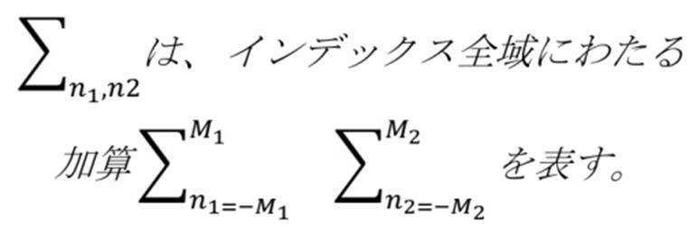
パワースペクトル算出部100Bは、二次元離散フーリエ変換部100Aでの変換結果に基づいて、下記の数式(3)を用いて正規化相互パワースペクトルR(k1,k2)を算出する。
The power spectrum calculation unit 100B calculates the normalized mutual power spectrum R(k 1 , k 2 ) using the following mathematical expression (3) based on the conversion result of the two-dimensional discrete Fourier transform unit 100A.

数式(3)に含まれる関数の意味は以下の通りである。
The meanings of the functions included in formula (3) are as follows.

二次元逆離散フーリエ変換部100Cは、位相限定相関関数r(n1,n2)を、正規化相互パワースペクトルの二次元逆フーリエ変換として下記の数式(4)を用いて算出する。
The two-dimensional inverse discrete Fourier transform unit 100C calculates the phase-only correlation function r(n 1 , n 2 ) as the two-dimensional inverse Fourier transform of the normalized mutual power spectrum by using the following mathematical expression (4).
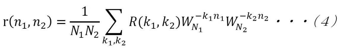
数式(4)に含まれるΣk1,k2は、以下のように定義されている。
Σ k1, k2 included in the mathematical expression (4) is defined as follows.

右側画像110R及び左側画像110Lが類似している場合、位相限定相関関数r(n1,n2)は、図13に示すように、デルタ関数に近い極めて鋭いピーク(相関ピーク)rpを有する。相関ピークrpの高さは右側画像110R及び左側画像110Lの位相差スペクトルの線形性を表しており、位相差スペクトルが周波数に対して線形であれば、相関ピークの高さは1になる。相関ピークの高さは右側画像110Rと左側画像110Lとの類似度の尺度として有用である。また、相関ピークの座標は右側画像110Rと左側画像110Lとの相対的な位置ずれに対応している。
When the right-side image 110R and the left-side image 110L are similar to each other, the phase-only correlation function r(n 1 , n 2 ) has an extremely sharp peak (correlation peak) rp close to a delta function as shown in FIG. The height of the correlation peak rp represents the linearity of the phase difference spectrum of the right-side image 110R and the left-side image 110L. If the phase difference spectrum is linear with respect to the frequency, the height of the correlation peak is 1. The height of the correlation peak is useful as a measure of the similarity between the right image 110R and the left image 110L. Further, the coordinates of the correlation peak correspond to the relative positional deviation between the right side image 110R and the left side image 110L.
なお、2つの画像に対して二次元離散フーリエ変換が行われ、二次元離散フーリエ変換の結果に基づいて正規化相互パワースペクトルが算出され、正規化相互パワースペクトルが二次元逆フーリエ変換されて位相限定相関関数が算出される。算出された正規化相互パワースペクトルが二次元逆フーリエ変換される詳細な算出方法については、“http://www.aoki.ecei.tohoku.ac.jp/~ito/voll_030.pdf”等に開示されている。
Two-dimensional discrete Fourier transform is performed on the two images, the normalized mutual power spectrum is calculated based on the result of the two-dimensional discrete Fourier transform, and the normalized mutual power spectrum is two-dimensional inverse Fourier transformed to obtain the phase. The limited correlation function is calculated. A detailed calculation method for performing a two-dimensional inverse Fourier transform on the calculated normalized mutual power spectrum is disclosed in "http://www.aoki.ecei.tokyo.ac.jp/~ito/vol_030.pdf" and the like. Has been done.
図14には、二次元逆離散フーリエ変換部100Cにより算出された位相限定相関関数r(n1,n2)により示される2次元画像である逆フーリエ変換画像111が示されている。すなわち、逆フーリエ変換画像111は、正規化相互パワースペクトルの逆フーリエ変換画像である。逆フーリエ変換画像111内には、図13に示す相関ピークrpの位置に対応する位置に相関ピーク111Pが表れている。逆フーリエ変換画像111は、二次元逆離散フーリエ変換部100CによってRAM88の逆フーリエ変換画像記憶領域88Bに記憶される。
FIG. 14 shows an inverse Fourier transform image 111, which is a two-dimensional image represented by the phase-only correlation function r(n1, n2) calculated by the two-dimensional inverse discrete Fourier transform unit 100C. That is, the inverse Fourier transform image 111 is an inverse Fourier transform image of the normalized mutual power spectrum. In the inverse Fourier transform image 111, the correlation peak 111P appears at the position corresponding to the position of the correlation peak rp shown in FIG. The inverse Fourier transform image 111 is stored in the inverse Fourier transform image storage area 88B of the RAM 88 by the two-dimensional inverse discrete Fourier transform unit 100C.
ピーク座標特定部100Dは、逆フーリエ変換画像111内から相関ピーク111Pの座標(以下、「ピーク座標」と称する)を特定する。ピーク座標は、逆フーリエ変換画像111内の最大の画素値の位置を示す座標である。従って、ピーク座標特定部100Dは、図15に示すように、原点(X0,Y0)から終点座標(Xn,Yn)にかけて、破線矢印の方向に沿って、逆フーリエ変換画像111の1画素毎の画素値を取得し、最大の画素値の位置を示す座標を特定する。図15に示す例では、ピーク座標特定部100Dは、逆フーリエ変換画像111の最上行から最下行にかけて、1行単位で1画素ずつ画素値を取得し、最大の画素値を更新すると共に、最大の画素値の位置を示す座標も更新することで、ピーク座標を特定している。
The peak coordinate specifying unit 100D specifies the coordinates of the correlation peak 111P (hereinafter, referred to as "peak coordinates") from the inverse Fourier transform image 111. The peak coordinates are coordinates indicating the position of the maximum pixel value in the inverse Fourier transform image 111. Therefore, as shown in FIG. 15, the peak coordinate specifying unit 100D extends from the origin (X 0 , Y 0 ) to the end point coordinates (X n , Y n ) along the direction of the broken line arrow in the inverse Fourier transform image 111. The pixel value for each pixel is acquired, and the coordinates indicating the position of the maximum pixel value are specified. In the example illustrated in FIG. 15, the peak coordinate specifying unit 100D acquires pixel values pixel by pixel from the uppermost row to the lowermost row of the inverse Fourier transform image 111, updating the maximum pixel value and updating the maximum pixel value. The peak coordinates are specified by updating the coordinates indicating the position of the pixel value of.
変位ベクトル算出部100Eは、ピーク座標特定部100Dにより特定されたピーク座標に基づいて変位ベクトルを算出する。ここで言う「変位ベクトル」とは、右側画像110R及び左側画像110Lのうちの一方に対する他方の変位ベクトルを含む。本実施形態では、変位ベクトル算出部110Eにより、右側画像110Rに対する左側画像110Lの変位ベクトルが算出される。
The displacement vector calculation unit 100E calculates the displacement vector based on the peak coordinates identified by the peak coordinate identification unit 100D. The “displacement vector” referred to here includes the displacement vector of one of the right image 110R and the left image 110L with respect to the other. In the present embodiment, the displacement vector calculation unit 110E calculates the displacement vector of the left image 110L with respect to the right image 110R.
ここで、ピーク座標を(Px,Py)とすると、変位ベクトル(dx,dy)は、数式(1)に示すf(n1,n2)に対する数式(2)の移動量であり、(px-α1,Py-α2)で求められる。“α1”とは、“(width-1)/2”を指し、“α2”とは、“(height-1)/2”を指す。“width”は、図15に示す「幅」であり、“height”とは、図15に示す「高さ」である。
Here, assuming that the peak coordinates are (P x , P y ), the displacement vector (d x , d y ) is the movement amount of Equation (2) with respect to f(n 1 , n 2 ) shown in Equation (1). Yes, and is calculated by (p x −α1, P y −α2). "Α1" refers to "(width-1)/2", and "α2" refers to "(height-1)/2". "Width" is the "width" shown in FIG. 15, and "height" is the "height" shown in FIG.
合焦位置算出部100Fは、変位ベクトル算出部100Eによって算出された変位ベクトルに基づいて、下記の数式(5)を用いて合焦位置GPを所定の位置に合わせるのに要する調節量dzを算出する。ここで言う「所定の位置」とは、後述の観察位置(例えば、角膜20A1の頂点の位置)を指す。また、ここで言う「調節量」とは、観察している位置である観察位置(例えば、ボケている現位置(非合焦状態の位置))から図16に示す合焦面GG迄のずれ量に相当し、手術用顕微鏡本体16の移動方向及び移動量を含む。ここで、合焦面GGとは、フォーカスの合っている面を意味する。合焦面GGは、オートフォーカスする面であるという観点で、「目的面」とも言える。図16に示す例では、観察位置が角膜20A1上にあり、眼部20Aの瞳孔に合焦面GGが形成されている。合焦面GGは、術野28の全体について被写界深度が最も深くなる合焦面(目的面)である。合焦面GGの位置、すなわち、眼部20Aの瞳孔の位置は、右側画像110R及び/又は左側画像110Lが合焦位置算出部100Fによって画像解析されることによって特定される。
The focus position calculation unit 100F calculates an adjustment amount dz required to adjust the focus position GP to a predetermined position by using the following mathematical expression (5) based on the displacement vector calculated by the displacement vector calculation unit 100E. To do. The “predetermined position” mentioned here refers to an observation position (for example, the position of the apex of the cornea 20A1) described later. The "adjustment amount" referred to here is the shift from the observing position (for example, the current position that is out of focus (the position in the out-of-focus state)) to the focusing surface GG shown in FIG. It corresponds to the amount and includes the movement direction and movement amount of the surgical microscope body 16. Here, the in-focus surface GG means a surface in focus. The focusing surface GG can also be called a “target surface” from the viewpoint of being a surface for autofocusing. In the example shown in FIG. 16, the observation position is on the cornea 20A1 and the focusing surface GG is formed in the pupil of the eye 20A. The focusing surface GG is a focusing surface (target surface) that has the deepest depth of field for the entire operative field 28. The position of the focusing surface GG, that is, the position of the pupil of the eye 20A is specified by performing image analysis of the right-side image 110R and/or the left-side image 110L by the focusing position calculation unit 100F.
下記の数式(5)は、独立変数としてdxg,de,gを有し、従属変数として調節量dzを有する数式である。図16に示すように、gは、対物レンズ26から合焦面GGまでの合焦距離であり、deは、右側偏向素子68Rと左側偏向素子68Lとの距離である。また、dxgは、合焦面GGでの視差発生方向のずれ量である。なお、一例として図17に示すように、dxpは、右側術野像109Rに基づいて生成された右側画像110Rと左側術野像109Lに基づいて生成された左側画像とのずれ量である。
The following formula (5) is a formula having dx g , de, g as the independent variables and the adjustment amount dz as the dependent variable. As shown in FIG. 16, g is the focusing distance from the objective lens 26 to the focusing surface GG, and de is the distance between the right deflection element 68R and the left deflection element 68L. Further, dx g is the amount of deviation in the parallax generation direction on the focusing surface GG. Note that, as an example, as shown in FIG. 17, dx p is a shift amount between the right side image 110R generated based on the right side surgical field image 109R and the left side image generated based on the left side surgical field image 109L.

dxgは、下記の数式(6)によって規定されている。下記の数式(6)は、独立変数としてβ,dxiを有し、従属変数としてdxgを有する。また、下記の数式(6)に示すように、dxiは、wpに対するdxpの割合として規定されている。
dx g is defined by the following mathematical expression (6). Equation (6) below has β,dx i as the independent variable and dx g as the dependent variable. Further, as shown in the following mathematical expression (6), dx i is defined as the ratio of dx p to w p .
一例として図17に示すように、dxiは、右側撮像素子62Rの受光面(像面)に結像された観察像である右側術野像109Rと左側撮像素子62Lの受光面(像面)に結像された観察像である左側術野像109Lとのずれ量である。また、βは、光学系総合ズーム倍率である。光学系総合ズーム倍率とは、現時点で設定されているズーム倍率に基づいて算出される値である。更に、数式(6)において、wpは、右側撮像素子62R及び左側撮像素子62Lに含まれる画素間の幅、すなわち、画素間のピッチである。
As an example, as shown in FIG. 17, dx i is a right operative field image 109R that is an observation image formed on the light receiving surface (image surface) of the right imaging element 62R and the light receiving surface (image surface) of the left imaging element 62L. This is the amount of deviation from the left operative field image 109L, which is the observation image formed in FIG. Further, β is a total zoom magnification of the optical system. The optical system total zoom magnification is a value calculated based on the zoom magnification set at the present time. Further, in Expression (6), w p is a width between pixels included in the right image pickup element 62R and the left image pickup element 62L, that is, a pitch between pixels.
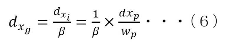
コントラスト値算出部100Gは、右側画像110R及び左側画像110Lの各々のコントラスト値を算出する。また、コントラスト値算出部100Gは、右側画像110Rのコントラスト値と左側画像110Lのコントラスト値との加算平均値を算出する。
The contrast value calculation unit 100G calculates the contrast value of each of the right side image 110R and the left side image 110L. Further, the contrast value calculation unit 100G calculates an arithmetic mean value of the contrast value of the right image 110R and the contrast value of the left image 110L.
なお、コントラスト値算出部100Gによって算出されるコントラスト値は、いわゆるコントラストAFに供するコントラスト値として主にモータ制御部102Bによって用いられる。すなわち、合焦位置調節用モータ80は、コントラスト値算出部100Gで算出されたコントラスト値に基づいて、モータ制御部102Bによって制御される。
The contrast value calculated by the contrast value calculation unit 100G is mainly used by the motor control unit 102B as a contrast value used for so-called contrast AF. That is, the focus position adjusting motor 80 is controlled by the motor control unit 102B based on the contrast value calculated by the contrast value calculation unit 100G.
制御部102は、表示制御部102A及びモータ制御部102Bを有する。表示制御部102Aは、フォーカス調節画面14B(図6参照)及び観察用画面14G(図8参照)を選択的にディスプレイ14に表示させる。表示制御部102Aは、受付装置19によって受け付けられた指示に応じてフォーカス調節画面14B及び観察用画面14Gの表示態様を変更する制御をディスプレイ14に対して行う。
The control unit 102 has a display control unit 102A and a motor control unit 102B. The display control unit 102A selectively displays the focus adjustment screen 14B (see FIG. 6) and the observation screen 14G (see FIG. 8) on the display 14. The display control unit 102A controls the display 14 to change the display mode of the focus adjustment screen 14B and the observation screen 14G according to the instruction received by the reception device 19.
表示制御部102Aは、ディスプレイ14に観察用画面14Gを表示させる場合、撮像画像記憶領域88Aから右側画像110R及び左側画像110Lを表示用フレームレート(例えば、60fps)で取得する。表示制御部102Aは、取得した右側画像110R及び左側画像110Lに対して、互いに直交する直線偏光をかける。そして、表示制御部102Aは、直線偏光をかけた右側画像110Rと左側画像110Lとを重ねてディスプレイ14に表示用フレームレートに従って表示させる。これにより、図9に示すように、立体視画像112がライブビュー画像或いはリアルタイム画像として観察用画面14Gから飛び出た位置でユーザ24によって視認される。
When displaying the observation screen 14G on the display 14, the display control unit 102A acquires the right side image 110R and the left side image 110L from the captured image storage area 88A at the display frame rate (for example, 60 fps). The display control unit 102A applies linearly polarized light orthogonal to each other to the acquired right image 110R and left image 110L. Then, the display control unit 102A superimposes the right-side image 110R and the left-side image 110L, which are linearly polarized, on the display 14 according to the display frame rate. As a result, as shown in FIG. 9, the stereoscopic image 112 is visually recognized by the user 24 as a live view image or a real-time image at a position protruding from the observation screen 14G.
合焦位置算出部100Fによって調節量dzは、表示用フレームレートに基づいて定められた出力タイミングでモータ制御部102Bに出力される。ここで言う「出力タイミング」とは、例えば、表示用フレームレートの偶数倍のフレームレートで規定されたタイミングを含む。
The adjustment amount dz is output to the motor control unit 102B by the focus position calculation unit 100F at an output timing determined based on the display frame rate. The “output timing” mentioned here includes, for example, timing defined by a frame rate that is an even multiple of the display frame rate.
モータ制御部102Bは、合焦位置算出部100Fから入力された調節量dzに基づいて合焦位置GPが調節されるように駆動源94の合焦位置調節用モータ80(図4参照)を制御する。これにより、スライド機構78は、合焦位置調節用モータ80の動力を受けることで、合焦位置GPを合焦面GG(図16参照)に合わせるように手術用顕微鏡本体16を鉛直下方向DWに移動させる。
The motor control unit 102B controls the focus position adjusting motor 80 (see FIG. 4) of the drive source 94 so that the focus position GP is adjusted based on the adjustment amount dz input from the focus position calculation unit 100F. To do. As a result, the slide mechanism 78 receives the power of the focusing position adjusting motor 80, so that the surgical microscope main body 16 is moved vertically downward DW so that the focusing position GP is aligned with the focusing surface GG (see FIG. 16). Move to.
モータ制御部102Bは、合焦位置算出部100Fから調節量dzが入力されると、リアルタイム(即時的)に合焦位置GPが調節されるように駆動源94の合焦位置調節用モータ80(図4参照)を制御する。従って、合焦位置GPを合焦面GGに追従させつつ右側画像110R及び左側画像110Lが生成され、生成された右側画像110R及び左側画像110Lがライブビュー方式で重ねて表示される(図10参照)。これにより、合焦面GGについて合焦された状態の立体視画像112(図9参照)がライブビュー画像或いはリアルタイム画像としてユーザ24によって視認される。
When the adjustment amount dz is input from the focus position calculation unit 100F, the motor control unit 102B adjusts the focus position adjustment motor 80 (of the drive source 94) so that the focus position GP is adjusted in real time (immediately). (See FIG. 4). Therefore, the right-side image 110R and the left-side image 110L are generated while making the in-focus position GP follow the in-focus surface GG, and the generated right-side image 110R and the left-side image 110L are overlaid and displayed by the live view method (see FIG. 10). ). Accordingly, the stereoscopic image 112 (see FIG. 9) in the focused state on the focusing surface GG is visually recognized by the user 24 as a live view image or a real-time image.
モータ制御部102Bは、絞り開度が変更されるように右側絞り駆動用モータ78R(図4参照)及び左側絞り駆動用モータ78L(図4参照)を制御する。例えば、開度「小」ボタン14D3aがオンされることで、絞り開度が現時点の絞り開度よりも小さくなるように右側絞り駆動用モータ78R(図4参照)及び左側絞り駆動用モータ78Lが制御される。また、開度「大」ボタン14D3bがオンされることで、絞り開度が現時点の絞り開度よりも大きくなるように右側絞り駆動用モータ78R及び左側絞り駆動用モータ78Lが制御される。
The motor control unit 102B controls the right diaphragm driving motor 78R (see FIG. 4) and the left diaphragm driving motor 78L (see FIG. 4) so that the diaphragm opening is changed. For example, when the opening “small” button 14D3a is turned on, the right diaphragm driving motor 78R (see FIG. 4) and the left diaphragm driving motor 78L are set so that the diaphragm opening becomes smaller than the current diaphragm opening. Controlled. Further, when the opening "large" button 14D3b is turned on, the right diaphragm driving motor 78R and the left diaphragm driving motor 78L are controlled so that the diaphragm opening becomes larger than the current diaphragm opening.
モータ制御部102Bは、ズーム倍率が変更されるように右側変倍用モータ76R(図4参照)及び左側変倍用モータ76L(図4参照)を制御する。例えば、ズーム倍率「小」ボタン14D4aがオンされることで、ズーム倍率が現時点のズーム倍率よりも小さくなるように右側変倍用モータ76R及び左側変倍用モータ76Lが制御される。また、ズーム倍率「大」ボタン14D4bがオンされることで、ズーム倍率が現時点のズーム倍率よりも大きくなるように右側変倍用モータ76R及び左側変倍用モータ76Lが制御される。
The motor control unit 102B controls the right scaling motor 76R (see FIG. 4) and the left scaling motor 76L (see FIG. 4) so that the zoom magnification is changed. For example, when the zoom magnification “small” button 14D4a is turned on, the right scaling motor 76R and the left scaling motor 76L are controlled so that the zoom magnification becomes smaller than the current zoom magnification. Further, when the zoom magnification “large” button 14D4b is turned on, the right scaling motor 76R and the left scaling motor 76L are controlled so that the zoom magnification becomes larger than the current zoom magnification.
一方、モータ制御部102Bの制御で、合焦位置算出部100Fから入力された調節量dzに基づいて合焦位置GPが一旦調節されると、観察用画面14Gには、図18に示すように、表示制御部102Aによって、合焦位置指定案内情報14G1が表示される。
On the other hand, under the control of the motor control unit 102B, once the focus position GP is adjusted based on the adjustment amount dz input from the focus position calculation unit 100F, as shown in FIG. The display control unit 102A displays the focus position designation guidance information 14G1.
図18に示すように、合焦位置指定案内情報14G1は、案内メッセージ14G1a及びサンプル術野画像14G1bを有する情報である。図18に示す例では、案内メッセージ14G1aとサンプル術野画像14G1bとが隣接した状態で表示されている。また、図18に示す例では、案内メッセージ14G1aとして、「ピントを合わせたい領域があれば指定して下さい。」のメッセージと、サンプル術野画像14G1bの側を指し示す矢印とが表示されている。更に、図18に示す例では、サンプル術野画像14G1bとして、右側画像110Rが加工された静止画像が表示されている。サンプル術野画像14G1bは、右側画像110Rが加工された静止画像である。サンプル術野画像14G1bでは、眼部20Aの虹彩を示す虹彩画像領域15A、眼部20Aの瞳孔の周辺部を示す瞳孔周辺画像領域15B、及び眼部20Aの瞳孔の中心部を示す瞳孔中心画像領域15Cが区別可能に強調表示されている。
As shown in FIG. 18, the focus position designation guidance information 14G1 is information having a guidance message 14G1a and a sample surgical field image 14G1b. In the example shown in FIG. 18, the guidance message 14G1a and the sample surgical field image 14G1b are displayed adjacent to each other. Further, in the example shown in FIG. 18, as the guidance message 14G1a, a message “Please specify if there is an area to be focused on.” and an arrow pointing to the side of the sample surgical field image 14G1b are displayed. Further, in the example shown in FIG. 18, a still image obtained by processing the right image 110R is displayed as the sample surgical field image 14G1b. The sample surgical field image 14G1b is a still image obtained by processing the right image 110R. In the sample surgical field image 14G1b, an iris image region 15A showing the iris of the eye 20A, a pupil peripheral image region 15B showing the peripheral part of the pupil of the eye 20A, and a pupil center image region showing the central part of the pupil of the eye 20A. 15C is highlighted in a distinguishable manner.
表示制御部102Aは、サンプル術野画像14G1bを生成する場合、先ず、撮像画像記憶領域88Aから右側画像110Rを取得する。次に、表示制御部102Aは、取得した右側画像110Rに対して画像解析を行い、画像解析の結果に基づいて虹彩画像領域15A、瞳孔周辺画像領域15B、及び瞳孔中心画像領域15Cを特定する。そして、表示制御部102Aは、特定した虹彩画像領域15A、瞳孔周辺画像領域15B、及び瞳孔中心画像領域15Cの各々を他の画像領域と区別可能に右側画像110Rを加工して観察用画面14Gに表示する。
When generating the sample surgical field image 14G1b, the display control unit 102A first acquires the right image 110R from the captured image storage area 88A. Next, the display control unit 102A performs image analysis on the acquired right image 110R, and specifies the iris image region 15A, the pupil peripheral image region 15B, and the pupil center image region 15C based on the result of the image analysis. Then, the display control unit 102A processes the identified iris image area 15A, pupil peripheral image area 15B, and pupil center image area 15C so as to distinguish the right image 110R from other image areas, and displays the image on the observation screen 14G. indicate.
表示制御部102Aは、例えば、ユーザが操作する矢印ポインタ14Eがサンプル術野画像14G1bの表示領域に入り込むと、図19に示すように、サンプル術野画像14G1bに対して格子枠15を重ねて表示させる。図19に示す例では、サンプル術野画像14G1bが、格子枠15によって15個の領域に分割された状態で表示されている。サンプル術野画像14G1bが格子枠15で分割されることで複数の分割領域17が得られる。複数の分割領域17のうちの何れか1つが矢印ポインタ14Eによって指定されると、指定された分割領域17のサンプル術野画像14G1b上での位置を特定する位置特定情報が表示制御部102Aによってコントラスト値算出部100Gに出力される。ユーザ24が複数の分割領域17のうちの何れか1つを指定するには、ユーザ24が、タッチパッド40を操作することによって複数の分割領域17のうちの何れか1つに対して矢印ポインタ14Eを位置させ、左クリック用ボタン42をオンすればよい。位置特定情報とは、例えば、複数の分割領域17の各々に対して個別に付与されている固有の識別子を指す。図19に示す例では、サンプル術野画像14G1bが15分割されているので、各分割領域17に対して「001~015」の番号(識別子)が付与されている。複数の分割領域17のうちの何れか1つが矢印ポインタ14Eによって指定されることで、指定された分割領域17に付与されている番号から、指定された分割領域17が特定される。
For example, when the arrow pointer 14E operated by the user enters the display area of the sample surgical field image 14G1b, the display control unit 102A displays the lattice frame 15 over the sample surgical field image 14G1b as shown in FIG. Let In the example shown in FIG. 19, the sample surgical field image 14G1b is displayed in a state of being divided into 15 regions by the lattice frame 15. By dividing the sample surgical field image 14G1b by the lattice frame 15, a plurality of divided areas 17 are obtained. When any one of the plurality of divided areas 17 is designated by the arrow pointer 14E, the display control unit 102A contrasts the position specifying information for specifying the position of the specified divided area 17 on the sample surgical field image 14G1b. It is output to the value calculation unit 100G. In order for the user 24 to specify any one of the plurality of divided areas 17, the user 24 operates the touch pad 40 to indicate an arrow pointer to any one of the plurality of divided areas 17. 14E may be positioned and the left click button 42 may be turned on. The position specifying information refers to, for example, a unique identifier individually given to each of the plurality of divided areas 17. In the example shown in FIG. 19, since the sample surgical field image 14G1b is divided into 15, the divided regions 17 are given numbers (identifiers) “001 to 015”. When one of the plurality of divided areas 17 is designated by the arrow pointer 14E, the designated divided area 17 is specified from the number given to the designated divided area 17.
なお、矢印ポインタ14Eがサンプル術野画像14G1bの表示領域から離れると、格子枠15は表示制御部102Aによってサンプル術野画像14G1bの表示領域から消去される。
When the arrow pointer 14E moves away from the display area of the sample surgical field image 14G1b, the display control unit 102A erases the grid frame 15 from the display area of the sample surgical field image 14G1b.
分割領域17が指定されると、撮像画像記憶領域88Aには、右側画像110R及び左側画像110Lが記憶される。コントラスト値算出部100Gは、撮像画像記憶領域88Aに右側画像110R及び左側画像110Lが記憶されると、撮像画像記憶領域88Aからリアルタイム(即時的)に右側画像110R及び左側画像110Lを取得する。コントラスト値算出部100Gは、位置特定情報を受信し、受信した位置特定情報から、ユーザ24によって指定された分割領域17を特定する。そして、コントラスト値算出部100Gは、取得した右側画像110R及び左側画像110Lの各々の右側指定画像領域及び左側指定画像領域のコントラスト値を算出する。ここで言う「右側指定画像領域」とは、右側画像110Rのうち、矢印ポインタ14Eによって指定された分割領域17(図19参照)に対応する画像領域を指す。また、「左側指定画像領域」とは、左側画像110Lのうち、矢印ポインタ14Eによって指定された分割領域17(図19参照)に対応する画像領域を指す。コントラスト値算出部100Gは、右側指定画像領域のコントラスト値と左側指定画像領域のコントラスト値との加算平均値を算出する。コントラスト値算出部100Gは、算出した加算平均値をモータ制御部102Bに出力する。
When the divided area 17 is specified, the right image 110R and the left image 110L are stored in the captured image storage area 88A. When the right image 110R and the left image 110L are stored in the captured image storage area 88A, the contrast value calculation unit 100G acquires the right image 110R and the left image 110L from the captured image storage area 88A in real time (immediately). The contrast value calculation unit 100G receives the position specifying information, and specifies the divided area 17 designated by the user 24 from the received position specifying information. Then, the contrast value calculation unit 100G calculates the contrast values of the right side designated image area and the left side designated image area of the acquired right side image 110R and left side image 110L, respectively. The “right-side designated image area” here refers to an image area corresponding to the divided area 17 (see FIG. 19) designated by the arrow pointer 14E in the right-side image 110R. Further, the “left-side designated image area” refers to an image area corresponding to the divided area 17 (see FIG. 19) designated by the arrow pointer 14E in the left-side image 110L. The contrast value calculation unit 100G calculates an average value of the contrast value of the right-side designated image area and the contrast value of the left-side designated image area. The contrast value calculation unit 100G outputs the calculated addition average value to the motor control unit 102B.
モータ制御部102Bは、コントラスト値算出部100Gから入力された加算平均値に基づいて、AF処理のコントラストAFを実行することで、指定された分割領域17に対応する実空間領域が合焦状態となるように合焦位置を調節する。例えば、コントラスト値算出部100Gにより算出される加算平均値が最大となる位置に合焦位置を合わせるように合焦位置調節用モータ80(又は、スライド機構78)がモータ制御部102Bによって制御されることで、手術用顕微鏡本体16の位置が鉛直方向(図1~図4及び図16に示すZ方向)に沿って調節される。
The motor control unit 102B executes the contrast AF of the AF process based on the addition average value input from the contrast value calculation unit 100G, so that the real space region corresponding to the designated divided region 17 becomes the focused state. Adjust the focus position so that For example, the motor control unit 102B controls the focus position adjustment motor 80 (or the slide mechanism 78) so that the focus position is adjusted to the position where the arithmetic mean value calculated by the contrast value calculation unit 100G is the maximum. As a result, the position of the surgical microscope main body 16 is adjusted along the vertical direction (Z direction shown in FIGS. 1 to 4 and 16).
次に、手術用顕微鏡12に対してMFモードが設定される場合について説明する。
Next, the case where the MF mode is set for the surgical microscope 12 will be described.
フォーカス調節画面14B(図6参照)又は観察用画面14G(図8参照)がディスプレイ14に表示されている状態において、MFモードボタン14D2がオンされると、CPU84によって手術用顕微鏡12に対してMFモードが設定される。
When the MF mode button 14D2 is turned on in the state where the focus adjustment screen 14B (see FIG. 6) or the observation screen 14G (see FIG. 8) is displayed on the display 14, the CPU 84 causes the MF mode for the surgical microscope 12 with respect to the surgical microscope 12. The mode is set.
手術用顕微鏡12に対してMFモードが設定されると、図20に示すように、MFモードボタン14D2が強調表示され、AFモードボタン14D1が反転表示される。
When the MF mode is set for the surgical microscope 12, the MF mode button 14D2 is highlighted and the AF mode button 14D1 is highlighted as shown in FIG.
図20に示すように、MFモード時のメニューウィンドウ14Dは、AFモード時に比べ、フォーカス支援指示受付部21を更に備える点が異なる。フォーカス支援指示受付部21は、ソフトキーの集合であり、表示制御部102Aに対してフォーカス支援情報を観察用画面14G内に表示させる指示を受け付ける。フォーカス支援情報は、ユーザ24によるMF(Manual Focus)の調節作業を支援する情報であり、後述の第1~第6フォーカス支援情報に大別される。フォーカス支援情報は、本開示の技術に係る「示唆情報」の一例であり、示唆情報とは、合焦位置を術野28の指定領域に合わせるために、調節装置18による合焦位置の調節に要する指示の内容を示唆する情報を含む。例えば、示唆情報は、合焦位置の調節状態を視覚的に認識させる情報を含む。具体的には、示唆情報は、合焦位置の調節状態(例えば、フォーカスが合っている合焦状態、フォーカスが合っていない非合焦状態、及び/又は該非合焦状態においてどの程度フォーカスがずれているか等)を視覚的に認識させて、合焦位置の調節を視覚的に支援する情報を含む。また、例えば、示唆情報は、ユーザ24による合焦位置の調節を視覚的に誘導する情報を含む。なお、上記指示の内容は、例えば、本実施形態における上記調節量に相当する情報を含む。
As shown in FIG. 20, the menu window 14D in the MF mode is different from that in the AF mode in that the menu window 14D further includes a focus support instruction receiving unit 21. The focus support instruction receiving unit 21 is a set of soft keys, and receives an instruction to display the focus support information on the observation screen 14G to the display control unit 102A. The focus support information is information for supporting the MF (Manual Focus) adjustment work by the user 24, and is roughly classified into first to sixth focus support information described below. The focus support information is an example of “indication information” according to the technology of the present disclosure, and the indication information refers to adjustment of the in-focus position by the adjustment device 18 in order to adjust the in-focus position to the designated area of the operative field 28. Contains information that suggests the content of the required instruction. For example, the suggestion information includes information that allows the adjustment state of the focus position to be visually recognized. Specifically, the suggestion information is an adjustment state of the in-focus position (for example, in-focus state in focus, out-of-focus state out of focus, and/or how much the focus shifts in the out-of-focus state. It includes information that visually assists the adjustment of the in-focus position. Further, for example, the suggestion information includes information that visually guides the adjustment of the focus position by the user 24. In addition, the content of the instruction includes, for example, information corresponding to the adjustment amount in the present embodiment.
フォーカス支援指示受付部21は、第1フォーカス支援情報ボタン21A、第2フォーカス支援情報ボタン21B、第3フォーカス支援情報ボタン21C、第4フォーカス支援情報ボタン21D、第5フォーカス支援情報ボタン21E、及び第6フォーカス支援情報ボタン21Fを有する。なお、以下、説明の便宜上、第1フォーカス支援情報ボタン21A、第2フォーカス支援情報ボタン21B、第3フォーカス支援情報ボタン21C、第4フォーカス支援情報ボタン21D、第5フォーカス支援情報ボタン21E、及び第6フォーカス支援情報ボタン21Fを区別して説明する必要がない場合、符号付さずに「フォーカス支援情報ボタン」と称する。なお、フォーカス支援情報ボタンをオンする方法は、観察開始ボタン14Cをオンする方法と同じである。
The focus assistance instruction receiving unit 21 includes a first focus assistance information button 21A, a second focus assistance information button 21B, a third focus assistance information button 21C, a fourth focus assistance information button 21D, a fifth focus assistance information button 21E, and a fifth focus assistance information button 21E. It has 6 focus support information buttons 21F. Note that, for convenience of description, the first focus support information button 21A, the second focus support information button 21B, the third focus support information button 21C, the fourth focus support information button 21D, the fifth focus support information button 21E, and the fourth focus support information button 21E. When it is not necessary to distinguish and explain the 6 focus support information buttons 21F, they are referred to as "focus support information buttons" without reference numerals. The method for turning on the focus support information button is the same as the method for turning on the observation start button 14C.
手術用顕微鏡12の動作モードがMFモードの場合、図21に示すように、制御部102は、表示制御部102A、モータ制御部102B、及びフォーカス支援情報制御部102Cを有する。
When the operation mode of the surgical microscope 12 is the MF mode, the control unit 102 has a display control unit 102A, a motor control unit 102B, and a focus support information control unit 102C, as shown in FIG.
第1フォーカス支援情報ボタン21Aがオンされると、フォーカス支援情報生成部102Cは、撮像画像記憶領域88Aから右側画像110Rを取得し、右側画像110Rに基づいて、第1フォーカス支援情報120(図22参照)を生成する。
When the first focus support information button 21A is turned on, the focus support information generation unit 102C acquires the right image 110R from the captured image storage area 88A, and based on the right image 110R, the first focus support information 120 (FIG. 22). Reference) is generated.
フォーカス支援情報生成部102Cは、生成した第1フォーカス支援情報120を表示制御部102Aに出力する。表示制御部102Aは、フォーカス支援情報生成部102Cから入力された第1フォーカス支援情報120をディスプレイ14に出力し、図22に示すように、観察用画面14Gの上半分の表示領域に表示させる。また、表示制御部102Aは、図22に示すように、観察用画面14Gの下半分の表示領域に右側画像110Rと左側画像110Lとを重ねてライブビュー方式で表示する。
The focus support information generation unit 102C outputs the generated first focus support information 120 to the display control unit 102A. The display control unit 102A outputs the first focus support information 120 input from the focus support information generation unit 102C to the display 14 to display it in the upper half display area of the observation screen 14G as illustrated in FIG. In addition, as shown in FIG. 22, the display control unit 102A displays the right-side image 110R and the left-side image 110L in the live view mode by superimposing the right-side image 110R and the left-side image 110L on the lower half display area of the observation screen 14G.
図22に示すように、第1フォーカス支援情報120は、サンプル術野画像120Aと案内メッセージ120Bとを含む情報である。サンプル術野画像120Aは、サンプル術野画像14G1b(図18参照)を拡大した画像に相当する画像である。サンプル術野画像120Aは、右側画像110Rが加工された静止画像である。
As shown in FIG. 22, the first focus support information 120 is information including a sample surgical field image 120A and a guidance message 120B. The sample surgical field image 120A is an image corresponding to an image obtained by enlarging the sample surgical field image 14G1b (see FIG. 18). The sample surgical field image 120A is a still image obtained by processing the right image 110R.
なお、ここでは、サンプル術野画像120Aとして、右側画像110Rが加工された静止画像を例示しているが、本開示の技術はこれに限定されず、例えば、左側画像110Lが加工された静止画像が用いられるようにしてもよい。また、右側画像110Rが加工された静止画像と左側画像110Lが加工された静止画像とが併用されるように構成してもよい。
Although the still image in which the right image 110R is processed is illustrated as the sample surgical field image 120A here, the technique of the present disclosure is not limited thereto, and for example, the still image in which the left image 110L is processed is illustrated. May be used. Alternatively, the still image obtained by processing the right image 110R and the still image obtained by processing the left image 110L may be used together.
サンプル術野画像120Aは、虹彩画像領域120A1、瞳孔周辺画像領域120A2、及び瞳孔中心画像領域120A3を区別して認識できるように、それぞれ強調表示されている。虹彩画像領域120A1は、図18に示す虹彩画像領域15Aに相当する画像領域である。瞳孔周辺画像領域120A2は、図18に示す瞳孔周辺画像領域15Bに相当する画像領域である。瞳孔中心画像領域120A3は、図18に示す瞳孔中心画像領域15Cに相当する画像領域である。
The sample surgical field image 120A is highlighted so that the iris image area 120A1, the pupil periphery image area 120A2, and the pupil center image area 120A3 can be distinguished and recognized. The iris image area 120A1 is an image area corresponding to the iris image area 15A shown in FIG. The pupil peripheral image area 120A2 is an image area corresponding to the pupil peripheral image area 15B shown in FIG. The pupil center image area 120A3 is an image area corresponding to the pupil center image area 15C shown in FIG.
案内メッセージ120Bは、サンプル術野画像120A内の強調表示された領域が合焦領域の候補であることをユーザ24に示唆するメッセージ(本開示の技術に係る「示唆情報」の一例)である。図22に示す例では、「強調表示された領域が合焦領域の候補です。」のメッセージが、虹彩画像領域120A1、瞳孔周辺画像領域120A2、及び瞳孔中心画像領域120A3と重ならない領域に表示されている。
The guidance message 120B is a message (an example of “indication information” according to the technology of the present disclosure) that indicates to the user 24 that the highlighted region in the sample surgical field image 120A is a candidate for the focused region. In the example shown in FIG. 22, the message “The highlighted area is a focus area candidate” is displayed in an area that does not overlap the iris image area 120A1, the pupil peripheral image area 120A2, and the pupil center image area 120A3. ing.
そして、ユーザ24は、リアルタイムに表示されている第1フォーカス支援情報120、及び図9に示す立体視画像112を視認しながら、フットスイッチ(図1及び図5に示す符号46,48参照)などが含まれる受付装置19(フォーカス操作部)を操作することでMFの調節作業を実施する。MFの調節作業とは、例えば、フットスイッチの操作を行い、ユーザ24によるMF操作の入力を含む。例えば、モータ制御部102Bは、ユーザ24によるフットスイッチの操作に応じて、合焦位置調節用モータ80を制御する。すなわち、モータ制御部102Bは、上方向移動用フットスイッチ46に対する踏み込みのストローク量に応じた移動量だけ手術用顕微鏡本体16を鉛直上方向UP(図4参照)に移動させる。また、モータ制御部102Bは、下方向移動用フットスイッチ48に対する踏み込みのストローク量に応じた移動量だけ手術用顕微鏡本体16を鉛直下方向DW(図4参照)に移動させる。なお、ここで言う「ストローク量に応じた移動量」とは、例えば、ストローク量が多くなるに従って手術用顕微鏡本体16の移動量も多くなることを意味する。
Then, the user 24 visually recognizes the first focus support information 120 displayed in real time and the stereoscopic image 112 shown in FIG. 9 while viewing the foot switch (see reference numerals 46 and 48 shown in FIGS. 1 and 5) and the like. MF adjustment work is performed by operating the reception device 19 (focus operation unit) including the. The MF adjustment work includes, for example, operating the foot switch and inputting the MF operation by the user 24. For example, the motor control unit 102B controls the focusing position adjusting motor 80 according to the operation of the foot switch by the user 24. That is, the motor control unit 102B moves the surgical microscope main body 16 in the vertical upward direction UP (see FIG. 4) by a movement amount corresponding to the stroke amount of the depression with respect to the upward movement foot switch 46. Further, the motor control unit 102B moves the surgical microscope main body 16 in the vertical downward direction DW (see FIG. 4) by an amount of movement corresponding to the stroke amount of the depression with respect to the downward movement foot switch 48. The “movement amount according to the stroke amount” here means that, for example, the movement amount of the surgical microscope main body 16 increases as the stroke amount increases.
また、第2フォーカス支援情報ボタン21Bがオンされると、フォーカス支援情報生成部102Cは、第2フォーカス支援情報としてアルファブレンド画像122(図23参照)を生成する。アルファブレンドとは、2つの画像を係数(α値)により合成する処理を指す。アルファブレンドの具体例としては、透過される部分が定義されたマスク画像を表示させ、かつ、マスク画像で定義された透過される部分に対して、透過させる画像として指定された画像を透過させる処理が挙げられる。フォーカス支援情報生成部102Cは、撮像画像記憶領域88Aからリアルタイム(即時的)に右側画像110R及び左側画像110Lを取得する。フォーカス支援情報生成部102Cは、右側画像110R及び左側画像110Lを取得すると、右側画像110Rの半透明画像である右側半透明画像122A(図23参照)と、左側画像110Lの半透明画像である左側半透明画像122B(図23参照)とをリアルタイム(即時的)に生成する。そして、フォーカス支援情報生成部102Cは、右側半透明画像122Aと左側半透明画像122Bとを重ねたアルファブレンド画像122を生成し、生成したアルファブレンド画像122を表示制御部102Aに出力する。
When the second focus support information button 21B is turned on, the focus support information generation unit 102C generates the alpha blend image 122 (see FIG. 23) as the second focus support information. Alpha blending refers to a process of combining two images with a coefficient (α value). As a specific example of alpha blending, a process of displaying a mask image in which a transparent portion is defined and transmitting an image designated as a transparent image to the transparent portion defined in the mask image Is mentioned. The focus support information generation unit 102C acquires the right side image 110R and the left side image 110L from the captured image storage area 88A in real time (immediately). When the focus support information generation unit 102C acquires the right-side image 110R and the left-side image 110L, the right-side translucent image 122A (see FIG. 23), which is the translucent image of the right-side image 110R, and the left side, which is the translucent image of the left-side image 110L. The semi-transparent image 122B (see FIG. 23) is generated in real time (immediately). Then, the focus support information generation unit 102C generates the alpha blended image 122 in which the right-side semi-transparent image 122A and the left-side semi-transparent image 122B are overlapped, and outputs the generated alpha blended image 122 to the display control unit 102A.
表示制御部102Aは、フォーカス支援情報生成部102Cから入力されたアルファブレンド画像122をディスプレイ14に出力し、図23に示すように、観察用画面14Gの上半分の表示領域にライブビュー方式で表示させる。すなわち、表示制御部102Aは、調節装置18による調節に連動してアルファブレンド画像122をリアルタイムに更新する制御を行う。また、表示制御部102Aは、図23に示すように、観察用画面14Gの下半分の表示領域に右側画像110Rと左側画像110Lとを重ねてライブビュー方式で表示する。
The display control unit 102A outputs the alpha blended image 122 input from the focus support information generation unit 102C to the display 14, and the live view method is used to display the alpha blended image 122 in the upper half display area of the observation screen 14G as illustrated in FIG. Let That is, the display control unit 102A performs control for updating the alpha blended image 122 in real time in synchronization with the adjustment by the adjustment device 18. In addition, as shown in FIG. 23, the display control unit 102A superimposes the right image 110R and the left image 110L on the lower half display area of the observation screen 14G and displays them in a live view manner.
ユーザ24は、第1フォーカス支援情報120が観察用画面14Gに表示されている場合と同様に、アルファブレンド画像122、及び図9に示す立体視画像112を視認しながら、フットスイッチ(図1及び図5に示す符号46,48参照)を操作することでMFの調節作業を実施する。MFの調節作業が実施されることで、図23及び図24A~図24Cに示すように、右側半透明画像122Aと左側半透明画像122Bとが視差発生方向PR1に沿って徐々に移動する。視差発生方向PR1は、右側半透明画像122Aと左側半透明画像122Bとの間の視差の発生方向を含む方向である。
Similarly to the case where the first focus support information 120 is displayed on the observation screen 14G, the user 24 visually recognizes the alpha blended image 122 and the stereoscopic image 112 shown in FIG. The MF adjustment operation is performed by operating the reference numerals 46 and 48 shown in FIG. By performing the MF adjustment operation, the right-side semi-transparent image 122A and the left-side semi-transparent image 122B gradually move along the parallax generation direction PR1, as shown in FIGS. 23 and 24A to 24C. The parallax generation direction PR1 is a direction including the parallax generation direction between the right-side semi-transparent image 122A and the left-side semi-transparent image 122B.
図23に示すように、右側半透明画像122Aは、虹彩を示す虹彩画像領域の外縁である虹彩外縁122A1と、瞳孔を示す瞳孔画像領域の外縁である瞳孔外縁122A2とを有する。また、左側半透明画像122Bは、虹彩を示す虹彩画像領域の外縁である虹彩外縁122B1と、瞳孔を示す瞳孔画像領域の外縁である瞳孔外縁122B2とを有する。
As shown in FIG. 23, the right-side semi-transparent image 122A has an iris outer edge 122A1 which is an outer edge of an iris image area showing an iris and a pupil outer edge 122A2 which is an outer edge of a pupil image area showing a pupil. The left-side semi-transparent image 122B has an iris outer edge 122B1 which is an outer edge of an iris image area showing an iris and a pupil outer edge 122B2 which is an outer edge of a pupil image area showing a pupil.
図23及び図24Aに示す例では、虹彩外縁122A1と虹彩外縁122B1とは重なっていない。また、瞳孔外縁122A2と瞳孔外縁122B2とも重なっていない。これは、眼部20Aの虹彩の外縁が非合焦状態であり、眼部20Aの瞳孔の外縁も非合焦状態であることを意味する。
In the example shown in FIGS. 23 and 24A, the iris outer edge 122A1 and the iris outer edge 122B1 do not overlap. Further, the pupil outer edge 122A2 and the pupil outer edge 122B2 do not overlap. This means that the outer edge of the iris of the eye 20A is out of focus, and the outer edge of the pupil of the eye 20A is out of focus.
図24Bに示す例では、瞳孔外縁122A2と瞳孔外縁122B2とは重なっていないが、虹彩外縁122A1と虹彩外縁122B1とは重なっている。これは、眼部20Aの瞳孔の外縁が非合焦状態であり、眼部20Aの虹彩の外縁が合焦状態であることを意味する。
In the example shown in FIG. 24B, the pupil outer edge 122A2 and the pupil outer edge 122B2 do not overlap, but the iris outer edge 122A1 and the iris outer edge 122B1 overlap. This means that the outer edge of the pupil of the eye 20A is out of focus and the outer edge of the iris of the eye 20A is in focus.
図24Cに示す例では、虹彩外縁122A1と虹彩外縁122B1とは重なっていないが、瞳孔外縁122A2と瞳孔外縁122B2とは重なっている。これは、眼部20Aの虹彩の外縁が非合焦状態であり、眼部20Aの瞳孔の外縁が合焦状態であることを意味する。
In the example shown in FIG. 24C, the iris outer edge 122A1 and the iris outer edge 122B1 do not overlap, but the pupil outer edge 122A2 and the pupil outer edge 122B2 overlap. This means that the outer edge of the iris of the eye 20A is out of focus and the outer edge of the pupil of the eye 20A is in focus.
次に、第3フォーカス支援情報ボタン21Cがオンされると、フォーカス支援情報生成部102Cは、第3フォーカス支援情報としてスプリットイメージ124(図25参照)を生成する。
Next, when the third focus support information button 21C is turned on, the focus support information generation unit 102C generates the split image 124 (see FIG. 25) as the third focus support information.
スプリットイメージ124は、表示領域が複数に分割された分割画像(例えば上下方向に分割された各画像)であって、ピントのずれに応じて視差発生方向(例えば左右方向)にずれ、ピントが合った状態だと視差発生方向のずれがなくなる分割画像を指す。図25に示す例では、スプリットイメージ124は、右側分割画像110R1と、左側分割画像110L1とを視差発生方向PR2と交差する方向(図25に示す例では図中正面視上下方向)に交互に組み合わせた複数分割(図25に示す例では13分割)の画像である。ここで、視差発生方向PR2と交差する方向は、本開示の技術に係る「特定方向」の一例である。右側分割画像110R1は、右側画像110Rが視差発生方向PR2と交差する方向に分割されることで得られる画像である。左側分割画像110L1は、左側画像110Lが視差発生方向PR2と交差する方向に分割されることで得られる画像である。スプリットイメージ124に含まれる右側分割画像110R1は、合焦状態に応じて所定方向(図24に示す例では視差発生方向PR2(図中正面視左右方向))にずれる。
The split image 124 is a divided image (for example, each image divided in the vertical direction) into which the display area is divided, and is shifted in the parallax generation direction (for example, the horizontal direction) according to the focus shift, and the focus is adjusted. In the closed state, it means a divided image in which there is no deviation in the direction of parallax generation. In the example shown in FIG. 25, in the split image 124, the right-side divided image 110R1 and the left-side divided image 110L1 are alternately combined in the direction intersecting the parallax generation direction PR2 (in the example shown in FIG. 25, the vertical direction in the front view). It is an image of multiple divisions (13 divisions in the example shown in FIG. 25). Here, the direction intersecting with the parallax generation direction PR2 is an example of the “specific direction” according to the technique of the present disclosure. The right divided image 110R1 is an image obtained by dividing the right image 110R in a direction intersecting the parallax generation direction PR2. The left side divided image 110L1 is an image obtained by dividing the left side image 110L in a direction intersecting with the parallax generation direction PR2. The right divided image 110R1 included in the split image 124 is displaced in a predetermined direction (parallax generation direction PR2 (horizontal direction in front view in the figure) in the example shown in FIG. 24) according to the focused state.
図25に示すように、スプリットイメージ124は、虹彩を示す虹彩画像領域の外縁である虹彩外縁124Bと、瞳孔を示す瞳孔画像領域の外縁である瞳孔外縁124Cと、眼部20Aを示す眼部領域の外縁である眼部外縁124Dと、を有する。
As illustrated in FIG. 25, the split image 124 includes an iris outer edge 124B that is an outer edge of an iris image region that indicates an iris, a pupil outer edge 124C that is an outer edge of a pupil image region that indicates a pupil, and an eye region that indicates the eye part 20A. And an eye outer edge 124D that is the outer edge of the.
スプリットイメージ124の視差発生方向PR2側の外輪郭124Aは、強調表示されている。ここで言う「外輪郭124A」とは、スプリットイメージ124に含まれる特徴的な領域の外輪郭を指す。特徴的な領域の外輪郭としては、虹彩外縁124B、瞳孔外縁124C、及び眼部外縁124D等が挙げられる。また、ここで言う「強調表示」とは、外輪郭124Aを縁取った態様での表示を指す。外輪郭124Aの強調表示は、本開示の技術に係る「第1強調表示」の一例である。
The outer contour 124A of the split image 124 on the parallax generation direction PR2 side is highlighted. The “outer contour 124</b>A” mentioned here refers to the outer contour of a characteristic region included in the split image 124. Examples of the outer contour of the characteristic region include the iris outer edge 124B, the pupil outer edge 124C, and the eye outer edge 124D. Further, the "highlighted display" referred to here means a display in a mode in which the outer contour 124A is framed. The highlighting of the outer contour 124A is an example of “first highlighting” according to the technique of the present disclosure.
フォーカス支援情報生成部102Cは、撮像画像記憶領域88Aに右側画像110R及び左側画像110Lが記憶されると、撮像画像記憶領域88Aからリアルタイム(即時的)に右側画像110R及び左側画像110Lを取得する。フォーカス支援情報生成部102Cは、右側画像110R及び左側画像110Lを取得すると、取得した右側画像110R及び左側画像110Lに基づいてスプリットイメージ124をリアルタイム(即時的)に生成する。そして、フォーカス支援情報生成部102Cは、生成したスプリットイメージ124を表示制御部102Aに出力する。
When the right image 110R and the left image 110L are stored in the captured image storage area 88A, the focus support information generation unit 102C acquires the right image 110R and the left image 110L from the captured image storage area 88A in real time (immediately). When the focus support information generation unit 102C acquires the right side image 110R and the left side image 110L, the focus support information generation unit 102C generates the split image 124 in real time (immediately) based on the acquired right side image 110R and left side image 110L. Then, the focus support information generation unit 102C outputs the generated split image 124 to the display control unit 102A.
表示制御部102Aは、フォーカス支援情報生成部102Cから入力されたスプリットイメージ124をディスプレイ14に出力し、図25に示すように、観察用画面14Gの上半分の表示領域にライブビュー方式で表示させる。すなわち、表示制御部102Aは、調節装置18による調節に連動してスプリットイメージ124をリアルタイムに更新する制御を行う。また、表示制御部102Aは、図25に示すように、観察用画面14Gの下半分の表示領域に右側画像110Rと左側画像110Lとを重ねてライブビュー方式で表示する。
The display control unit 102A outputs the split image 124 input from the focus support information generation unit 102C to the display 14 and causes the display 14 to display the split image 124 in the upper half display area of the observation screen 14G by the live view method. .. That is, the display control unit 102A performs control for updating the split image 124 in real time in synchronization with the adjustment by the adjustment device 18. Further, as shown in FIG. 25, the display control unit 102A superimposes the right image 110R and the left image 110L on the lower half display area of the observation screen 14G and displays them in a live view manner.
ユーザ24は、第1フォーカス支援情報120が観察用画面14Gに表示されている場合と同様に、スプリットイメージ124、及び図9に示す立体視画像112を視認しながら、フットスイッチ(図1及び図5に示す符号46,48参照)を操作することでMFの調節作業を実施する。MFの調節作業が実施されることで、図25及び図26A~図26Cに示すように、スプリットイメージ124に含まれる右側分割画像110R1と左側分割画像110L1とが視差発生方向PR2に沿って相対的に徐々に移動する。
Similarly to the case where the first focus support information 120 is displayed on the observation screen 14G, the user 24 visually recognizes the split image 124 and the stereoscopic image 112 shown in FIG. 9 while viewing the foot switch (FIG. 1 and FIG. The MF adjustment operation is performed by operating the reference numerals 46 and 48 shown in FIG. By performing the MF adjustment work, as shown in FIGS. 25 and 26A to 26C, the right-side divided image 110R1 and the left-side divided image 110L1 included in the split image 124 are relatively moved along the parallax generation direction PR2. Gradually move to.
図25及び図26Aに示す例では、虹彩外縁124Bは、視差発生方向PR2にずれている。また、瞳孔外縁124Cも、視差発生方向PR2にずれている。これは、眼部20Aの虹彩の外縁が非合焦状態であり、眼部20Aの瞳孔の外縁も非合焦状態であることを意味する。
In the example shown in FIGS. 25 and 26A, the iris outer edge 124B is displaced in the parallax generation direction PR2. Further, the pupil outer edge 124C is also displaced in the parallax generation direction PR2. This means that the outer edge of the iris of the eye 20A is out of focus, and the outer edge of the pupil of the eye 20A is out of focus.
図26Bに示す例では、瞳孔外縁124Cは、視差発生方向PR2にずれているが、虹彩外縁124Bは連続した線になっており、虹彩外縁124Bの視差発生方向PR2のずれが解消されている。これは、眼部20Aの瞳孔の外縁が非合焦状態であり、眼部20Aの虹彩の外縁が合焦状態であることを意味する。
In the example shown in FIG. 26B, the pupil outer edge 124C is shifted in the parallax generation direction PR2, but the iris outer edge 124B is a continuous line, and the shift of the iris outer edge 124B in the parallax generation direction PR2 is eliminated. This means that the outer edge of the pupil of the eye 20A is out of focus and the outer edge of the iris of the eye 20A is in focus.
図26Cに示す例では、虹彩外縁124Bは、視差発生方向PR2にずれているが、瞳孔外縁124Cは連続した線になっており、瞳孔外縁124Cの視差発生方向PR2のずれが解消されている。これは、眼部20Aの虹彩の外縁が非合焦状態であり、眼部20Aの瞳孔の外縁が合焦状態であることを意味する。
In the example shown in FIG. 26C, the iris outer edge 124B is displaced in the parallax generation direction PR2, but the pupil outer edge 124C is a continuous line, and the deviation of the pupil outer edge 124C in the parallax generation direction PR2 is eliminated. This means that the outer edge of the iris of the eye 20A is out of focus and the outer edge of the pupil of the eye 20A is in focus.
図25に示す観察用画面14Gが表示されている状態で、受付装置19によって要移動量情報表示指示(例、入力信号)が受け付けられた場合に、表示制御部102Aは、図27に示すように、空き表示領域14G0に案内メッセージ126を表示する。空き表示領域14G0は、観察用画面14Gの上半分の表示領域のうちのスプリットイメージ124及び観察終了ボタン14Fとは異なる表示領域である。
When the reception device 19 receives a movement amount required information display instruction (eg, input signal) while the observation screen 14G shown in FIG. 25 is displayed, the display control unit 102A changes the display screen as shown in FIG. Then, the guidance message 126 is displayed in the empty display area 14G0. The empty display area 14G0 is a display area different from the split image 124 and the observation end button 14F in the upper half display area of the observation screen 14G.
ここで、要移動量情報表示指示とは、要移動量情報の表示の指示を指す。要移動量情報は、眼部20Aのうちの指定領域を合焦状態にするために手術用顕微鏡本体16の鉛直方向(例えば、図16に示すZ方向)への移動に要する移動量(例えば、上述の調整量dz)を示す情報である。要移動量情報により示される移動量は、位相限定相関法と上述した数式(5),数式(6)とを用いることによって算出される。要移動量情報としては、図28に示す上方向要移動量情報128と、図29に示す下方向要移動量情報130とが挙げられる。なお、本実施形態では、要移動量情報表示指示として、空き表示領域14G0に矢印ポインタ14Eを位置させた状態での左クリック用ボタン42のダブルクリックが採用されている。
Here, the instruction to display the required movement amount information refers to an instruction to display the required movement amount information. The required movement amount information is the movement amount required to move the surgical microscope body 16 in the vertical direction (for example, the Z direction shown in FIG. 16) in order to bring the designated region of the eye 20A into the focused state (for example, This is information indicating the above-mentioned adjustment amount dz). The movement amount indicated by the required movement amount information is calculated by using the phase-only correlation method and the above-described equations (5) and (6). The required movement amount information includes upward movement required amount information 128 shown in FIG. 28 and downward movement required amount information 130 shown in FIG. 29. In this embodiment, as the movement amount information display instruction, double-clicking the left click button 42 with the arrow pointer 14E positioned in the empty display area 14G0 is adopted.
図27に示すように、案内メッセージ126は、スプリットイメージ124内の一部領域を指定することでピントを合わせたい領域を指定することをユーザ24に促すメッセージである。図27には、案内メッセージ126として、「ピントを合わせたい領域があれば指定して下さい。」とのメッセージと、スプリットイメージ124の側を指し示す矢印とが例示されている。
As shown in FIG. 27, the guidance message 126 is a message that prompts the user 24 to specify a region to focus on by designating a partial region in the split image 124. In FIG. 27, as the guidance message 126, a message “Please specify if there is an area to be focused on.” and an arrow pointing to the side of the split image 124 are illustrated.
図27に示すように、ユーザ24は、スプリットイメージ124内のうち、ピントを合わせたい領域に矢印ポインタ14Eを位置させ、左クリック用ボタン42をクリックする。例えば、図28に示すように、虹彩外縁124Bにかかる位置に矢印ポインタ14Eを位置させた状態で左クリック用ボタン42がクリックされると、表示制御部102Aは、空き領域14G0のうちの所定箇所に上方向要移動量情報128を表示する。ここで言う「所定箇所」とは、空き領域14G0のうち、スプリットイメージ124を介して案内メッセージ126と反対側の領域を含む。
As shown in FIG. 27, the user 24 positions the arrow pointer 14E in the area in the split image 124 where the user wants to focus and clicks the left click button 42. For example, as shown in FIG. 28, when the left click button 42 is clicked in a state where the arrow pointer 14E is located at a position where the iris outer edge 124B is located, the display control unit 102A causes the display control unit 102A to display a predetermined portion of the empty area 14G0. The upward movement required amount information 128 is displayed on. The “predetermined location” mentioned here includes the area on the opposite side of the guide message 126 via the split image 124 in the empty area 14G0.
図28に示す上方向要移動量情報128は、例えば、眼部20Aのうちの指定領域に合焦位置を合わせるために手術用顕微鏡本体16を鉛直上方向UP(図4参照)に移動させる移動量を示す情報である。ここで言う「眼部20Aのうちの指定領域」とは、眼部20Aのうち、フォーカスを合わせたい領域として矢印ポインタ14Eによって指定された領域(図28に示す例では、虹彩外縁124B)に対応する領域(眼部20Aの虹彩の外縁)を含む。
The upward movement required amount information 128 shown in FIG. 28 is, for example, movement for moving the surgical microscope main body 16 in the vertical upward direction UP (see FIG. 4) in order to adjust the focus position to the designated area of the eye portion 20A. This is information indicating the amount. The “designated area of the eye 20A” referred to here corresponds to the area of the eye 20A designated by the arrow pointer 14E as the area to be focused (the iris outer edge 124B in the example shown in FIG. 28). The region (the outer edge of the iris of the eye 20A) is included.
上方向要移動量情報128は、インジケータ128A及び矢印128Bを有する。インジケータ128Aは、スプリットイメージ124の表示が開始されてから現時点までの鉛直上方向UPへの手術用顕微鏡本体16の移動量を表している。矢印128Bは、インジケータ128A内に表示されており、眼部20Aのうちの指定領域に合焦位置を合わせる上で必要な鉛直上方向UPへの移動量を指し示している。
The upward movement required amount information 128 has an indicator 128A and an arrow 128B. The indicator 128A indicates the amount of movement of the surgical microscope main body 16 in the vertically upward direction UP from the start of displaying the split image 124 to the present time. The arrow 128B is displayed in the indicator 128A, and indicates the amount of movement in the vertically upward direction UP necessary for adjusting the focus position to the designated area of the eye 20A.
図29に示す下方向要移動量情報130は、眼部20Aのうちの指定領域に合焦位置を合わせるために手術用顕微鏡本体16を鉛直下方向DW(図4参照)に移動させる移動量を示す情報である。図29に示す例では、矢印ポインタ14Eによって瞳孔外縁124Cが指定されている。従って、図29に示す例において、「眼部20Aのうちの指定領域」とは、眼部20Aの瞳孔の外縁を指す。
The downward movement required amount information 130 shown in FIG. 29 is the movement amount for moving the surgical microscope main body 16 in the vertical downward direction DW (see FIG. 4) in order to adjust the focus position to the designated area of the eye portion 20A. It is information to show. In the example shown in FIG. 29, the outer peripheral edge 124C of the pupil is designated by the arrow pointer 14E. Therefore, in the example shown in FIG. 29, the “designated area of the eye 20A” refers to the outer edge of the pupil of the eye 20A.
下方向要移動量情報130は、インジケータ130A及び矢印130Bを有する。インジケータ130Aは、スプリットイメージ124の表示が開始されてから現時点までの鉛直下方向DWへの手術用顕微鏡本体16の移動量を表している。矢印130Bは、インジケータ130A内に表示されており、眼部20Aのうちの指定領域に合焦位置を合わせる上で必要な鉛直下方向DWへの移動量を指し示している。
The downward movement required amount information 130 has an indicator 130A and an arrow 130B. The indicator 130A indicates the amount of movement of the surgical microscope body 16 in the vertical downward direction DW from the start of displaying the split image 124 to the present time. The arrow 130B is displayed in the indicator 130A, and indicates the amount of movement in the vertically downward direction DW necessary for adjusting the focus position to the designated area of the eye 20A.
更に、第4フォーカス支援情報ボタン21Dがオンされると、フォーカス支援情報生成部102Cは、第4フォーカス支援情報として差分画像132(図30参照)を生成する。
Further, when the fourth focus support information button 21D is turned on, the focus support information generation unit 102C generates a difference image 132 (see FIG. 30) as the fourth focus support information.
差分画像132は、本開示の技術に係る「相違度画像」の一例である。ここで言う「相違度画像」とは、右側画像110Rと左側画像110Lとの対応する画素位置の画素値の相違度を表した画像を指す。相違度としては、減算値、除算値、減算値の絶対値、減算値と除算値との組み合わせ、減算値の絶対値と除算値との組み合わせ、又はこれらに対する加算及び/又は乗算の組み合わせ等が挙げられる。
The difference image 132 is an example of a “difference degree image” according to the technique of the present disclosure. The "difference degree image" referred to here is an image showing the degree of difference in pixel values at corresponding pixel positions between the right image 110R and the left image 110L. The degree of difference may be a subtraction value, a division value, an absolute value of the subtraction value, a combination of the subtraction value and the division value, a combination of the absolute value of the subtraction value and the division value, or a combination of addition and/or multiplication for these. Can be mentioned.
減算値とは、例えば、右側画像110R及び左側画像110Lのうちの一方の各画素位置の画素値から他方に含まれる対応する画素位置の画素値を減じて得た減算値を指す。除算値とは、右側画像110R及び左側画像110Lのうちの一方の各画素位置の画素値に対して他方に含まれる対応する画素位置の画素値を除して得た除算値を指す。
The subtraction value is, for example, a subtraction value obtained by subtracting the pixel value of the corresponding pixel position included in the other from the pixel value of each pixel position of the right image 110R and the left image 110L. The division value refers to a division value obtained by dividing the pixel value of each pixel position of one of the right image 110R and the left image 110L by the pixel value of the corresponding pixel position included in the other.
フォーカス支援情報生成部102Cは、撮像画像記憶領域88Aに右側画像110R及び左側画像110Lが記憶されると、撮像画像記憶領域88Aからリアルタイム(即時的)に右側画像110R及び左側画像110Lを取得する。フォーカス支援情報生成部102Cは、右側画像110R及び左側画像110Lを取得すると、右側画像110Rと左側画像110Lとの間で対応する画素位置間での差分値をリアルタイム(即時的)に算出する。フォーカス支援情報生成部102Cは、算出した差分値を、右側画像110Rと左側画像110Lとの間で対応する画素位置毎にマッピングすることで、差分画像132(図30参照)を生成する。そして、フォーカス支援情報生成部102Cは、生成した差分画像132を表示制御部102Aに出力する。
When the right image 110R and the left image 110L are stored in the captured image storage area 88A, the focus support information generation unit 102C acquires the right image 110R and the left image 110L from the captured image storage area 88A in real time (immediately). When the focus support information generation unit 102C acquires the right image 110R and the left image 110L, the focus support information generation unit 102C calculates in real time (immediately) a difference value between corresponding pixel positions between the right image 110R and the left image 110L. The focus support information generation unit 102C generates the difference image 132 (see FIG. 30) by mapping the calculated difference value for each corresponding pixel position between the right image 110R and the left image 110L. Then, the focus support information generation unit 102C outputs the generated difference image 132 to the display control unit 102A.
表示制御部102Aは、フォーカス支援情報生成部102Cから入力された差分画像132をディスプレイ14に出力し、図30に示すように、観察用画面14Gの上半分の表示領域にライブビュー方式で表示させる。すなわち、表示制御部102Aは、調節装置18による調節に連動して差分画像132をリアルタイムに更新する制御を行う。また、表示制御部102Aは、図30に示すように、観察用画面14Gの下半分の表示領域に右側画像110Rと左側画像110Lとを重ねてライブビュー方式で表示する。
The display control unit 102A outputs the difference image 132 input from the focus support information generation unit 102C to the display 14, and causes the display 14 to display the difference image 132 in the upper half display area of the observation screen 14G by the live view method. .. That is, the display control unit 102A controls the difference image 132 to be updated in real time in synchronization with the adjustment by the adjustment device 18. Further, as shown in FIG. 30, the display control unit 102A displays the right-side image 110R and the left-side image 110L in the live view mode by superimposing the right-side image 110R and the left-side image 110L on the lower half display area of the observation screen 14G.
ユーザ24は、第1フォーカス支援情報120が観察用画面14Gに表示されている場合と同様に、差分画像132、及び図9に示す立体視画像112を視認しながら、フットスイッチ(図1及び図5に示す符号46,48参照)を操作することでMFの調節作業を実施する。MFの調節作業が実施されることで、図30及び図31A~図31Cに示すように、差分画像132に含まれる差分値の分布が視差発生方向PR3に沿って徐々に変位する。視差発生方向PR3とは、右側輪郭画像110R2と左側輪郭画像110L2との間の視差の発生方向を指す。
Similarly to the case where the first focus support information 120 is displayed on the observation screen 14G, the user 24 visually recognizes the differential image 132 and the stereoscopic image 112 shown in FIG. 9 while viewing the foot switch (FIG. 1 and FIG. The MF adjustment operation is performed by operating the reference numerals 46 and 48 shown in FIG. By performing the MF adjustment operation, the distribution of difference values included in the difference image 132 is gradually displaced along the parallax generation direction PR3, as shown in FIGS. 30 and 31A to 31C. The parallax generation direction PR3 refers to the direction in which parallax occurs between the right contour image 110R2 and the left contour image 110L2.
右側輪郭画像110R2は、右側画像110Rの特徴的な領域の外輪郭で形成された画像である。右側輪郭画像110R2は、虹彩を示す虹彩画像領域の外縁である右側虹彩外縁110R2aと、瞳孔を示す瞳孔画像領域の外縁である右側瞳孔外縁110R2bと、眼部20Aを示す眼部領域の外縁である右側眼部外縁110R2cと、を有する。
The right contour image 110R2 is an image formed by the outer contour of the characteristic region of the right image 110R. The right contour image 110R2 is a right iris outer edge 110R2a which is an outer edge of an iris image area showing an iris, a right pupil outer edge 110R2b which is an outer edge of a pupil image area showing a pupil, and an outer edge of an eye part area showing an eye part 20A. And a right eye outer edge 110R2c.
左側輪郭画像110L2は、左側画像110Lの特徴的な領域の外輪郭で形成された画像である。左側輪郭画像110L2は、虹彩を示す虹彩画像領域の外縁である左側虹彩外縁110L2aと、瞳孔を示す瞳孔画像領域の外縁である左側瞳孔外縁110L2bと、眼部20Aを示す眼部領域の外縁である左側眼部外縁110L2cと、を有する。
The left-side contour image 110L2 is an image formed by the outer contour of the characteristic region of the left-side image 110L. The left-side contour image 110L2 is a left-side iris outer edge 110L2a that is the outer edge of the iris image area indicating the iris, a left-side pupil outer edge 110L2b that is the outer edge of the pupil image area indicating the pupil, and an outer edge of the eye area indicating the eye 20A. And a left eye outer edge 110L2c.
図30及び図31Aに示す例では、右側虹彩外縁110R2aと左側虹彩外縁110L2aは重なっていない。また、右側瞳孔外縁110R2bと左側瞳孔外縁110L2bも重なっていない。更に、右側眼部外縁110R2cと左側眼部外縁110L2cも重なっていない。これは、眼部20Aの虹彩の外縁が非合焦状態であり、眼部20Aの瞳孔の外縁も非合焦状態であり、眼部20Aの外縁も非合焦状態であることを意味する。
In the example shown in FIGS. 30 and 31A, the right iris outer edge 110R2a and the left iris outer edge 110L2a do not overlap. Further, the right pupil outer edge 110R2b and the left pupil outer edge 110L2b do not overlap. Furthermore, the right eye outer edge 110R2c and the left eye outer edge 110L2c do not overlap. This means that the outer edge of the iris of the eye 20A is out of focus, the outer edge of the pupil of the eye 20A is out of focus, and the outer edge of the eye 20A is out of focus.
図31Bに示す例では、右側瞳孔外縁110R2bと左側瞳孔外縁110L2bは重なっていない。右側眼部外縁110R2cと左側眼部外縁110L2cも重なっていない。しかし、右側虹彩外縁110R2aと左側虹彩外縁110L2aは重なっている。これは、眼部20Aの瞳孔の外縁及び眼部20Aの外縁が非合焦状態であり、眼部20Aの虹彩の外縁が合焦状態であることを意味する。
In the example shown in FIG. 31B, the right pupil outer edge 110R2b and the left pupil outer edge 110L2b do not overlap. The right eye outer edge 110R2c and the left eye outer edge 110L2c also do not overlap. However, the right iris outer edge 110R2a and the left iris outer edge 110L2a overlap. This means that the outer edge of the pupil of the eye 20A and the outer edge of the eye 20A are out of focus, and the outer edge of the iris of the eye 20A is in focus.
図31Cに示す例では、右側虹彩外縁110R2aと左側虹彩外縁110L2aは重なっていない。右側眼部外縁110R2cと左側眼部外縁110L2cも重なっていない。しかし、右側瞳孔外縁110R2bと左側瞳孔外縁110L2bは重なっている。これは、眼部20Aの虹彩の外縁及び眼部20Aの外縁が非合焦状態であり、眼部20Aの瞳孔の外縁が合焦状態であることを意味する。
In the example shown in FIG. 31C, the right iris outer edge 110R2a and the left iris outer edge 110L2a do not overlap. The right eye outer edge 110R2c and the left eye outer edge 110L2c also do not overlap. However, the right pupil outer edge 110R2b and the left pupil outer edge 110L2b overlap. This means that the outer edge of the iris of the eye 20A and the outer edge of the eye 20A are out of focus, and the outer edge of the pupil of the eye 20A is in focus.
図31Bに示す例において、右側虹彩外縁110R2aと左側虹彩外縁110L2aとが重なっている部分は、表示制御部102Aによって強調表示される。この場合、右側虹彩外縁110R2a及び左側虹彩外縁110L2aのうちの少なくとも一方が縁取られた態様で表示される。これにより、眼部20Aのうち、合焦状態に達している領域が虹彩の外縁であることをユーザ24に対して容易に知覚させることができる。
In the example shown in FIG. 31B, the portion where the right iris outer edge 110R2a and the left iris outer edge 110L2a overlap is highlighted by the display control unit 102A. In this case, at least one of the right iris outer edge 110R2a and the left iris outer edge 110L2a is displayed in a bordered manner. This allows the user 24 to easily perceive that the region of the eye 20A that has reached the focused state is the outer edge of the iris.
また、図31Cに示す例において、右側瞳孔外縁110R2bと左側瞳孔外縁110L2bが重なっている部分は、表示制御部102Aによって強調表示される。この場合、右側瞳孔外縁110R2b及び左側瞳孔外縁110L2bのうちの少なくとも一方が縁取られた態様で表示される。これにより、眼部20Aのうち、合焦状態に達している領域が瞳孔の外縁であることをユーザ24に対して容易に知覚させることができる。
In the example shown in FIG. 31C, the display control unit 102A highlights the portion where the right pupil outer edge 110R2b and the left pupil outer edge 110L2b overlap. In this case, at least one of the right pupil outer edge 110R2b and the left pupil outer edge 110L2b is displayed in a framed manner. This allows the user 24 to easily perceive that the region of the eye 20A that has reached the focused state is the outer edge of the pupil.
なお、図31Bに示す例において、右側虹彩外縁110R2aと左側虹彩外縁110L2aとが重なっている部分の強調表示は、本開示の技術に係る第2強調表示の一例である。また、図31Cに示す例において、右側瞳孔外縁110R2bと左側瞳孔外縁110L2bが重なっている部分の強調表示も、本開示の技術に係る第2強調表示の一例である。
Note that in the example shown in FIG. 31B, the highlighting of the portion where the right iris outer edge 110R2a and the left iris outer edge 110L2a overlap is an example of the second highlighting according to the technique of the present disclosure. Further, in the example illustrated in FIG. 31C, highlighting of a portion where the right pupil outer edge 110R2b and the left pupil outer edge 110L2b overlap each other is also an example of second highlighting according to the technique of the present disclosure.
第5フォーカス支援情報ボタン21Eがオンされると、フォーカス支援情報生成部102Cは、第5フォーカス支援情報として右側コントラスト値インジケータ134R及び左側コントラスト値インジケータ134L(図32参照)を生成する。右側コントラスト値インジケータ134Rは、右側画像110Rのコントラスト値を示すインジケータであり、左側コントラスト値インジケータ134Lは、左側画像110Lのコントラスト値を示すインジケータである。
When the fifth focus support information button 21E is turned on, the focus support information generation unit 102C generates a right contrast value indicator 134R and a left contrast value indicator 134L (see FIG. 32) as the fifth focus support information. The right contrast value indicator 134R is an indicator showing the contrast value of the right image 110R, and the left contrast value indicator 134L is an indicator showing the contrast value of the left image 110L.
フォーカス支援情報生成部102Cは、撮像画像記憶領域88Aに右側画像110R及び左側画像110Lが記憶されると、撮像画像記憶領域88Aからリアルタイム(即時的)に右側画像110R及び左側画像110Lを取得する。フォーカス支援情報生成部102Cは、右側画像110R及び左側画像110Lを取得すると、取得した右側画像110R及び左側画像110Lの各々のコントラスト値をリアルタイム(即時的)に算出する。フォーカス支援情報生成部102Cは、右側画像110Rのコントラスト値に基づいて右側コントラスト値インジケータ134Rを生成し、左側画像110Lのコントラスト値に基づいて左側コントラスト値インジケータ134Lを生成する。そして、フォーカス支援情報生成部102Cは、生成した右側コントラスト値インジケータ134R及び左側コントラスト値インジケータ134Lを表示制御部102Aに出力する。
When the right image 110R and the left image 110L are stored in the captured image storage area 88A, the focus support information generation unit 102C acquires the right image 110R and the left image 110L from the captured image storage area 88A in real time (immediately). When the focus support information generation unit 102C acquires the right side image 110R and the left side image 110L, it calculates the contrast values of the acquired right side image 110R and left side image 110L in real time (immediately). The focus support information generation unit 102C generates the right contrast value indicator 134R based on the contrast value of the right image 110R, and generates the left contrast value indicator 134L based on the contrast value of the left image 110L. Then, the focus support information generation unit 102C outputs the generated right side contrast value indicator 134R and left side contrast value indicator 134L to the display control unit 102A.
表示制御部102Aは、撮像画像記憶領域88Aに右側画像110R及び左側画像110Lが記憶されると、撮像画像記憶領域88Aからリアルタイム(即時的)に右側画像110R及び左側画像110Lを取得する。表示制御部102Aは、取得した右側画像110R及び左側画像110Lに対して、互いに直交する直線偏光をかける。そして、表示制御部102Aは、図32に示すように、直線偏光をかけた右側画像110Rと左側画像110Lとを重ねて観察用画面14G内に表示用フレームレートに従って表示させる。
When the right image 110R and the left image 110L are stored in the captured image storage area 88A, the display control unit 102A acquires the right image 110R and the left image 110L from the captured image storage area 88A in real time (immediately). The display control unit 102A applies linearly polarized light orthogonal to each other to the acquired right image 110R and left image 110L. Then, as shown in FIG. 32, the display control unit 102A superimposes the right-side image 110R and the left-side image 110L, which are linearly polarized, on each other and displays them on the observation screen 14G in accordance with the display frame rate.
また、表示制御部102Aは、フォーカス支援情報生成部102Cから入力された右側コントラスト値インジケータ134Rに対して右側画像110Rと同様の直線偏光をかける。表示制御部102Aは、直線偏光をかけた右側コントラスト値インジケータ134Rを、図32に示すように、右側画像110Rと共に表示用フレームレートに従ってライブビュー方式でディスプレイ14に表示させる。すなわち、表示制御部102Aは、右側コントラスト値インジケータ134Rと右側画像110Rとを対応付けた状態で観察用画面14Gに表示させる。
Further, the display control unit 102A applies the same linear polarization as the right image 110R to the right contrast value indicator 134R input from the focus support information generation unit 102C. The display control unit 102A causes the right-side contrast value indicator 134R, which is linearly polarized, to be displayed on the display 14 by the live-view method along with the right-side image 110R according to the display frame rate, as shown in FIG. That is, the display control unit 102A causes the observation screen 14G to display the right contrast value indicator 134R and the right image 110R in association with each other.
更に、表示制御部102Aは、フォーカス支援情報生成部102Cから入力された左側コントラスト値インジケータ134Lに対して左側画像110Lと同様の直線偏光をかける。表示制御部102Aは、直線偏光をかけた左側コントラスト値インジケータ134Lを、図32に示すように、左側画像110Lと共に表示用フレームレートに従ってライブビュー方式でディスプレイ14に表示させる。すなわち、表示制御部102Aは、左側コントラスト値インジケータ134Lと左側画像110Lとを対応付けた状態で観察用画面14Gに表示させる。
Further, the display control unit 102A applies the same linear polarization as the left image 110L to the left contrast value indicator 134L input from the focus support information generation unit 102C. As shown in FIG. 32, the display control unit 102A causes the left-side contrast value indicator 134L, which is linearly polarized, to be displayed on the display 14 by the live-view method along with the left-side image 110L according to the display frame rate. That is, the display control unit 102A causes the observation screen 14G to display the left contrast value indicator 134L and the left image 110L in association with each other.
このように、右側画像110Rと共に右側コントラスト値インジケータ134Rがライブビュー方式で表示されると、右側画像110R及び右側コントラスト値インジケータ134Rが右眼用レンズ52R(図3参照)を透過する。これにより、図33Aに示すように、右側画像110R及び右側コントラスト値インジケータ134Rがユーザ24の右眼で視認される。
In this way, when the right-side image 110R and the right-side contrast value indicator 134R are displayed by the live view method, the right-side image 110R and the right-side contrast value indicator 134R pass through the right-eye lens 52R (see FIG. 3). Accordingly, as shown in FIG. 33A, the right image 110R and the right contrast value indicator 134R are visually recognized by the right eye of the user 24.
一方、左側画像110Lと共に左側コントラスト値インジケータ134Lがライブビュー方式で表示されると、左側画像110L及び左側コントラスト値インジケータ134Lが左眼用レンズ52L(図3参照)を透過する。これにより、図33Bに示すように、左側画像110L及び左側コントラスト値インジケータ134Lがユーザ24の左眼で視認される。
On the other hand, when the left side contrast value indicator 134L is displayed by the live view method together with the left side image 110L, the left side image 110L and the left side contrast value indicator 134L pass through the left eye lens 52L (see FIG. 3). Thereby, as shown in FIG. 33B, the left image 110L and the left contrast value indicator 134L are visually recognized by the left eye of the user 24.
なお、ここでは、右側コントラスト値インジケータ134Rに対して右側画像110Rと同様の直線偏光をかけ、左側コントラスト値インジケータ134Lに対して左側画像110Lと同様の直線偏光をかけたが、本開示の技術はこれに限定されない。すなわち、右側コントラスト値インジケータ134R及び左側コントラスト値インジケータ134Lを通常画像光58(図3参照)として右眼用レンズ52R及び左眼用レンズ52Lを透過させるようにしてもよい。
Here, the right-side contrast value indicator 134R is linearly polarized like the right-side image 110R, and the left-side contrast value indicator 134L is linearly-polarized like the left-side image 110L. It is not limited to this. That is, the right contrast value indicator 134R and the left contrast value indicator 134L may be transmitted as the normal image light 58 (see FIG. 3) through the right eye lens 52R and the left eye lens 52L.
また、図34に示すように、コントラスト値インジケータ136が表示制御部102Aによって観察用画面14Gに表示されるようにしてもよい。コントラスト値インジケータ136は、右側画像110Rのコントラスト値と左側画像110Lのコントラスト値との加算平均値を示すインジケータであり、フォーカス支援情報生成部102Cによって生成される。コントラスト値インジケータ136は、通常画像光58として右眼用レンズ52R及び左眼用レンズ52Lを透過する。
Further, as shown in FIG. 34, the contrast value indicator 136 may be displayed on the observation screen 14G by the display control unit 102A. The contrast value indicator 136 is an indicator that shows an average value of the contrast value of the right side image 110R and the contrast value of the left side image 110L, and is generated by the focus support information generating unit 102C. The contrast value indicator 136 passes through the right-eye lens 52R and the left-eye lens 52L as normal image light 58.
なお、本開示の技術はこれに限定されるものではなく、加算平均値に代えて、右側画像110Rのコントラスト値、又は左側画像110Lのコントラスト値を適用してもよい。
Note that the technology of the present disclosure is not limited to this, and the contrast value of the right image 110R or the left image 110L may be applied instead of the addition average value.
また、本開示の技術はこれに限定されるものではなく、図35に示すように、観察用画面14Gの上半分の表示領域をコントラスト確認用画面14G2とし、観察用画面14Gの下半分の表示領域を立体視画像表示用画面14G3としてもよい。コントラスト確認用画面14G2には、表示制御部102Aによって通常画像光58(図3参照)で画像が表示される。コントラスト確認用画面14G2には、表示制御部102Aによって右側画像110R及び右側コントラスト値インジケータ134Rがライブビュー方式で表示される。立体視画像表示用画面14G3には、直線偏光がかけられた右側画像110Rと左側画像110Lとが重ねられて表示用フレームレートに従って表示される。
The technique of the present disclosure is not limited to this, and as shown in FIG. 35, the display area of the upper half of the observation screen 14G is the contrast confirmation screen 14G2, and the lower half of the observation screen 14G is displayed. The area may be the stereoscopic image display screen 14G3. An image is displayed on the contrast confirmation screen 14G2 by the normal image light 58 (see FIG. 3) by the display control unit 102A. On the contrast confirmation screen 14G2, the right image 110R and the right contrast value indicator 134R are displayed by the display control unit 102A by the live view method. On the stereoscopic image display screen 14G3, the right-side image 110R and the left-side image 110L, which are linearly polarized, are superimposed and displayed according to the display frame rate.
また、本開示の技術はこれに限定されるものではなく、図36に示すように、コントラスト確認用画面14G2には、表示制御部102Aによって左側画像110R及び左側コントラスト値インジケータ134Lがライブビュー方式で表示されるようにしてもよい。この場合も、立体視画像表示用画面14G3には、直線偏光がかけられた右側画像110Rと左側画像110Lとが重ねられて表示用フレームレートに従って表示される。
Further, the technique of the present disclosure is not limited to this, and as shown in FIG. 36, the left side image 110R and the left side contrast value indicator 134L are displayed on the contrast confirmation screen 14G2 by the display control unit 102A in a live view system. It may be displayed. Also in this case, the right-side image 110R and the left-side image 110L, which are linearly polarized, are superimposed and displayed on the stereoscopic image display screen 14G3 in accordance with the display frame rate.
また、本開示の技術はこれに限定されるものではなく、図37に示すように、コントラスト確認用画面14G2には、表示制御部102Aによって右側参照画像138R及び左画像参照画像138Lがライブビュー方式で表示されるようにしてもよい。右側参照画像138Rは、右側画像110Rと右側コントラスト値インジケータ134Rとが対応付けられた状態の画像である。左画像参照画像138Lは、左側画像110Lと左側コントラスト値インジケータ134Lとが対応付けられた状態の画像である。
Further, the technique of the present disclosure is not limited to this, and as shown in FIG. 37, the display control unit 102A displays the right side reference image 138R and the left image reference image 138L on the contrast confirmation screen 14G2 by the live view method. May be displayed in. The right reference image 138R is an image in a state where the right image 110R and the right contrast value indicator 134R are associated with each other. The left image reference image 138L is an image in a state where the left image 110L and the left contrast value indicator 134L are associated with each other.
第6フォーカス支援情報ボタン21Fがオンされると、フォーカス支援情報生成部102Cは、第6フォーカス支援情報として右側コントラスト値グラフ140R及び左側コントラスト値グラフ140L(図38参照)を生成する。右側コントラスト値グラフ140Rは、右側画像110Rのコントラスト値の時間変化を示すグラフであり、左側コントラスト値グラフ140Lは、左側画像110Lのコントラスト値の時間変化を示すグラフである。
When the sixth focus support information button 21F is turned on, the focus support information generation unit 102C generates a right side contrast value graph 140R and a left side contrast value graph 140L (see FIG. 38) as the sixth focus support information. The right-side contrast value graph 140R is a graph showing the temporal change in the contrast value of the right-side image 110R, and the left-side contrast value graph 140L is a graph showing the temporal change in the contrast value of the left-side image 110L.
フォーカス支援情報生成部102Cは、撮像画像記憶領域88Aに右側画像110R及び左側画像110Lが記憶されると、撮像画像記憶領域88Aからリアルタイム(即時的)に右側画像110R及び左側画像110Lを取得する。フォーカス支援情報生成部102Cは、右側画像110R及び左側画像110Lを取得すると、取得した右側画像110R及び左側画像110Lの各々のコントラスト値をリアルタイム(即時的)に算出する。フォーカス支援情報生成部102Cは、右側画像110Rのコントラスト値の時系列に基づいて右側コントラスト値グラフ140Rを生成し、左側画像110Lのコントラスト値の時系列に基づいて左側コントラスト値グラフ140Lを生成する。そして、フォーカス支援情報生成部102Cは、生成した右側コントラスト値グラフ140R及び左側コントラスト値グラフ140Lを表示制御部102Aに出力する。
When the right image 110R and the left image 110L are stored in the captured image storage area 88A, the focus support information generation unit 102C acquires the right image 110R and the left image 110L from the captured image storage area 88A in real time (immediately). When the focus support information generation unit 102C acquires the right side image 110R and the left side image 110L, it calculates the contrast values of the acquired right side image 110R and left side image 110L in real time (immediately). The focus support information generation unit 102C generates the right contrast value graph 140R based on the time series of the contrast values of the right image 110R, and generates the left contrast value graph 140L based on the time series of the contrast values of the left image 110L. Then, the focus support information generation unit 102C outputs the generated right side contrast value graph 140R and left side contrast value graph 140L to the display control unit 102A.
表示制御部102Aは、撮像画像記憶領域88Aに右側画像110R及び左側画像110Lが記憶されると、撮像画像記憶領域88Aからリアルタイム(即時的)に右側画像110R及び左側画像110Lを取得する。表示制御部102Aは、取得した右側画像110R及び左側画像110Lに対して、互いに直交する直線偏光をかける。そして、表示制御部102Aは、図38に示すように、直線偏光をかけた右側画像110Rと左側画像110Lとを重ねて観察用画面14G内に表示用フレームレートに従って表示させる。
When the right image 110R and the left image 110L are stored in the captured image storage area 88A, the display control unit 102A acquires the right image 110R and the left image 110L from the captured image storage area 88A in real time (immediately). The display control unit 102A applies linearly polarized light orthogonal to each other to the acquired right image 110R and left image 110L. Then, as shown in FIG. 38, the display control unit 102A causes the right-side image 110R and the left-side image 110L, which are linearly polarized, to be superimposed and displayed on the observation screen 14G in accordance with the display frame rate.
また、表示制御部102Aは、フォーカス支援情報生成部102Cから入力された右側コントラスト値グラフ140Rに対して右側画像110Rと同様の直線偏光をかける。表示制御部102Aは、直線偏光をかけた右側コントラスト値グラフ140Rを、図38に示すように、右側画像110Rと共に表示用フレームレートに従ってライブビュー方式で表示させる。すなわち、表示制御部102Aは、右側コントラスト値グラフ140Rと右側画像110Rとを対応付けた状態で観察用画面14Gに表示する。
The display control unit 102A also applies the same linear polarization as the right image 110R to the right contrast value graph 140R input from the focus support information generation unit 102C. As shown in FIG. 38, the display control unit 102A displays the right-sided contrast value graph 140R, which is linearly polarized, together with the right-sided image 110R in the live view method according to the display frame rate. That is, the display control unit 102A displays the right contrast value graph 140R and the right image 110R on the observation screen 14G in a state of being associated with each other.
更に、表示制御部102Aは、フォーカス支援情報生成部102Cから入力された左側コントラスト値グラフ140Lに対して左側画像110Lと同様の直線偏光をかける。表示制御部102Aは、直線偏光をかけた左側コントラスト値グラフ140Lを、図38に示すように、左側画像110Lと共に表示用フレームレートに従ってライブビュー方式で表示させる。すなわち、表示制御部102Aは、左側コントラスト値グラフ140Lと左側画像110Lとを対応付けた状態で観察用画面14Gに表示する。
Further, the display control unit 102A applies the same linear polarization as the left image 110L to the left contrast value graph 140L input from the focus support information generation unit 102C. As shown in FIG. 38, the display control unit 102A causes the left-side contrast value graph 140L to which the linearly polarized light is applied to be displayed with the left-side image 110L in the live-view method according to the display frame rate. That is, the display control unit 102A displays the left-side contrast value graph 140L and the left-side image 110L in the associated state on the observation screen 14G.
このように、右側画像110Rと共に右側コントラスト値グラフ140Rがライブビュー方式で表示されると、右側画像110R及び右側コントラスト値グラフ140Rが右眼用レンズ52R(図3参照)を透過する。これにより、図39Aに示すように、右側画像110R及び右側コントラスト値グラフ140Rがユーザ24の右眼で視認される。
As described above, when the right-side image 110R and the right-side contrast value graph 140R are displayed by the live view method, the right-side image 110R and the right-side contrast value graph 140R pass through the right-eye lens 52R (see FIG. 3). Thereby, as shown in FIG. 39A, the right image 110R and the right contrast value graph 140R are visually recognized by the right eye of the user 24.
一方、左側画像110Lと共に左側コントラスト値グラフ140Lがライブビュー方式で表示されると、左側画像110L及び左側コントラスト値グラフ140Lが左眼用レンズ52L(図3参照)を透過する。これにより、図39Bに示すように、左側画像110L及び左側コントラスト値グラフ140Lがユーザ24の左眼で視認される。
On the other hand, when the left-side image 110L and the left-side contrast value graph 140L are displayed by the live view method, the left-side image 110L and the left-side contrast value graph 140L are transmitted through the left-eye lens 52L (see FIG. 3). Thereby, as shown in FIG. 39B, the left image 110L and the left contrast value graph 140L are visually recognized by the left eye of the user 24.
なお、ここでは、右側コントラスト値グラフ140Rに対して右側画像110Rと同様の直線偏光をかけ、左側コントラスト値グラフ140Lに対して左側画像110Lと同様の直線偏光をかけたが、本開示の技術はこれに限定されない。すなわち、右側コントラスト値グラフ140R及び左側コントラスト値グラフ140Lを通常画像光58(図3参照)として右眼用レンズ52R及び左眼用レンズ52Lを透過させるようにしてもよい。
Here, the right-side contrast value graph 140R is linearly polarized like the right-side image 110R, and the left-side contrast value graph 140L is linearly-polarized like the left-side image 110L. It is not limited to this. That is, the right-side contrast value graph 140R and the left-side contrast value graph 140L may be transmitted as the normal image light 58 (see FIG. 3) through the right-eye lens 52R and the left-eye lens 52L.
また、図40に示すように、コントラスト値グラフ142が表示制御部102Aによって観察用画面14Gに表示されるようにしてもよい。コントラスト値グラフ142は、右側コントラスト値グラフ140Rと左側コントラスト値グラフ140Lとの加算平均値を示すグラフであり、フォーカス支援情報生成部102Cによって生成される。コントラスト値グラフ142は、通常画像光58として右眼用レンズ52R及び左眼用レンズ52Lを透過する。
Further, as shown in FIG. 40, the contrast value graph 142 may be displayed on the observation screen 14G by the display control unit 102A. The contrast value graph 142 is a graph showing an arithmetic mean value of the right side contrast value graph 140R and the left side contrast value graph 140L, and is generated by the focus support information generation unit 102C. The contrast value graph 142 passes through the right-eye lens 52R and the left-eye lens 52L as the normal image light 58.
なお、本開示の技術はこれに限定されるものではなく、コントラスト値グラフ142に代えて、右側コントラスト値グラフ140R又は左側コントラスト値グラフ140Lを適用してもよい。
Note that the technology of the present disclosure is not limited to this, and the right side contrast value graph 140R or the left side contrast value graph 140L may be applied instead of the contrast value graph 142.
また、本開示の技術はこれに限定されるものではなく、図41に示すように、観察用画面14Gの上半分の表示領域をコントラスト変化確認用画面14G4とし、観察用画面14Gの下半分の表示領域を立体視画像表示用画面14G5としてもよい。コントラスト変化確認用画面14G4には、表示制御部102Aによって通常画像光58(図3参照)で画像が表示される。コントラスト変化確認用画面14G4には、表示制御部102Aによって右側画像110R及び右側コントラスト値グラフ140Rがライブビュー方式で表示される。立体視画像表示用画面14G5には、直線偏光がかけられた右側画像110Rと左側画像110Lとが重ねられて表示用フレームレートに従って表示される。
The technology of the present disclosure is not limited to this, and as shown in FIG. 41, the display area of the upper half of the observation screen 14G is the contrast change confirmation screen 14G4, and the lower half of the observation screen 14G is The display area may be the stereoscopic image display screen 14G5. An image is displayed on the contrast change confirmation screen 14G4 by the normal image light 58 (see FIG. 3) by the display control unit 102A. On the contrast change confirmation screen 14G4, the right image 110R and the right contrast value graph 140R are displayed by the live view method by the display control unit 102A. On the stereoscopic image display screen 14G5, the right-side image 110R and the left-side image 110L, which are linearly polarized, are superimposed and displayed according to the display frame rate.
また、本開示の技術はこれに限定されるものではなく、図42に示すように、コントラスト変化確認用画面14G4には、表示制御部102Aによって左側画像110R及び左側コントラスト値グラフ140Lがライブビュー方式で表示されるようにしてもよい。この場合も、立体視画像表示用画面14G3には、直線偏光がかけられた右側画像110Rと左側画像110Lとが重ねられて表示用フレームレートに従って表示される。
Further, the technique of the present disclosure is not limited to this, and as shown in FIG. 42, the display control unit 102A displays the left side image 110R and the left side contrast value graph 140L on the contrast change confirmation screen 14G4 by the live view method. May be displayed in. Also in this case, the right-side image 110R and the left-side image 110L, which are linearly polarized, are superimposed and displayed on the stereoscopic image display screen 14G3 in accordance with the display frame rate.
また、本開示の技術はこれに限定されるものではなく、図43に示すように、コントラスト変化確認用画面14G4には、表示制御部102Aによって右側参照画像144R及び左画像参照画像144Lがライブビュー方式で表示されるようにしてもよい。右側参照画像144Rは、右側画像110Rと右側コントラスト値グラフ140Rとが対応付けられた状態の画像である。左画像参照画像144Lは、左側画像110Lと左側コントラスト値グラフ140Lとが対応付けられた状態の画像である。
The technique of the present disclosure is not limited to this, and as shown in FIG. 43, the right side reference image 144R and the left image reference image 144L are live-viewed on the contrast change confirmation screen 14G4 by the display control unit 102A. You may make it display by a system. The right reference image 144R is an image in which the right image 110R and the right contrast value graph 140R are associated with each other. The left image reference image 144L is an image in which the left image 110L and the left contrast value graph 140L are associated with each other.
また、本開示の技術はこれに限定されるものではない。例えば、右側コントラスト値グラフ140R、左側コントラスト値グラフ140L、又はコントラスト値グラフ142上でコントラスト値が指定された場合に、指定されたコントラスト値が得られた時点での合焦位置が再現されるようにしてもよい。
Also, the technology of the present disclosure is not limited to this. For example, when the contrast value is specified on the right contrast value graph 140R, the left contrast value graph 140L, or the contrast value graph 142, the focus position at the time when the specified contrast value is obtained is reproduced. You can
例えば、図44に示すように、右側コントラスト値グラフ140Rが表示されている状態で、右側コントラスト値グラフ140R上でコントラスト値が指定された場合に、指定されたコントラスト値が得られた時点での合焦位置が再現される。この場合、前提として、右側コントラスト値グラフ140R上のコントラスト値と、これに対応する合焦位置を示す合焦位置情報とが対応付けられた状態でRAM88に記憶される。ユーザ24は、タッチパッド40を操作することで矢印ポインタ14Eを右側コントラスト値グラフ140R上に位置させる。そして、ユーザ24によって左クリック用ボタン42がクリックされると、モータ制御部102Bは、右側コントラスト値グラフ140Rのうちの矢印ポインタ14Eが位置している箇所のコントラスト値に対応する合焦位置情報をRAM88から取得する。そして、モータ制御部102Bは、RAM88から取得した合焦位置情報により示される合焦位置が再現されるように合焦位置調節用モータ80を制御する。
For example, as shown in FIG. 44, when the contrast value is specified on the right contrast value graph 140R in the state where the right contrast value graph 140R is displayed, at the time when the specified contrast value is obtained. The in-focus position is reproduced. In this case, as a premise, the contrast value on the right contrast value graph 140R and the focus position information indicating the focus position corresponding thereto are stored in the RAM 88 in a state of being associated with each other. The user 24 operates the touch pad 40 to position the arrow pointer 14E on the right contrast value graph 140R. Then, when the left click button 42 is clicked by the user 24, the motor control unit 102B displays focus position information corresponding to the contrast value of the portion of the right contrast value graph 140R where the arrow pointer 14E is located. It is acquired from the RAM 88. Then, the motor control unit 102B controls the focusing position adjusting motor 80 so that the focusing position indicated by the focusing position information acquired from the RAM 88 is reproduced.
また、本開示の技術はこれに限定されるものではない。例えば、図45に示すように、上述した第1~第6フォーカス支援情報が観察用画面14Gの上半分の表示領域に並べた状態で表示されるようにしてもよい。また、第1~第6フォーカス支援情報のうちの指定された複数のフォーカス支援情報が観察用画面14Gの上半分の表示領域に並べて表示されるようにしてもよい。
Also, the technology of the present disclosure is not limited to this. For example, as shown in FIG. 45, the above-described first to sixth focus support information may be displayed in a state of being arranged in the upper half display area of the observation screen 14G. Further, a plurality of designated focus support information out of the first to sixth focus support information may be displayed side by side in the upper half display area of the observation screen 14G.
次に、手術用顕微鏡12の作用について図46~図49を参照して説明する。
Next, the operation of the surgical microscope 12 will be described with reference to FIGS. 46 to 49.
図46には、CPU84によってフォーカスモード設定プログラム104に従って実行されるフォーカスモード設定処理の流れの一例が示されている。
FIG. 46 shows an example of the flow of focus mode setting processing executed by the CPU 84 in accordance with the focus mode setting program 104.
図46に示すフォーカスモード設定処理では、先ず、ステップST200で、CPU84は、フォーカスモード指示があったか否かを判定する。フォーカスモード指示があったか否かは、AFモードボタン14D1又はMFモードボタン14D2(図6参照)がオンされた否かによって判定される。ステップST200において、フォーカスモード指示がなかった場合は、判定が否定されて、フォーカス設定処理はステップST208へ移行する。ステップST200において、フォーカスモード指示があった場合は、判定が肯定されて、フォーカスモード設定処理はステップST202へ移行する。
In the focus mode setting process shown in FIG. 46, first, in step ST200, the CPU 84 determines whether or not there is a focus mode instruction. Whether or not there is a focus mode instruction is determined by whether or not the AF mode button 14D1 or the MF mode button 14D2 (see FIG. 6) is turned on. If there is no focus mode instruction in step ST200, the determination is negative, and the focus setting processing moves to step ST208. In step ST200, if there is a focus mode instruction, the determination is affirmative, and the focus mode setting process proceeds to step ST202.
ステップST202で、CPU84は、フォーカスモード指示がAFモード指示か否かを判定する。すなわち、ステップST202では、AFモードボタン14D1がオンされたか否かが判定される。ステップST202において、フォーカスモード指示がAFモード指示の場合は、判定が肯定されて、フォーカスモード設定処理はステップST204へ移行する。ステップST202において、フォーカスモード指示がMFモード指示の場合は、判定が否定されて、フォーカスモード設定処理はステップST210へ移行する。なお、フォーカスモード指示がMFモード指示の場合とは、MFモードボタン14D2がオンされた場合を指す。
In step ST202, the CPU 84 determines whether the focus mode instruction is the AF mode instruction. That is, in step ST202, it is determined whether or not the AF mode button 14D1 is turned on. If the focus mode instruction is the AF mode instruction in step ST202, the determination is affirmative, and the focus mode setting process proceeds to step ST204. If the focus mode instruction is the MF mode instruction in step ST202, the determination is negative, and the focus mode setting process proceeds to step ST210. The case where the focus mode instruction is the MF mode instruction means that the MF mode button 14D2 is turned on.
ステップST204で、CPU84は、手術用顕微鏡12の動作モードがMFモードか否かを判定する。ステップST204において、手術用顕微鏡12の動作モードがMFモードの場合は、判定が肯定されて、フォーカスモード設定処理はステップST206へ移行する。ステップST204において、手術用顕微鏡12の動作モードがAFモードの場合は、判定否定されて、フォーカスモード設定処理はステップST208へ移行する。
In step ST204, the CPU 84 determines whether the operation mode of the surgical microscope 12 is the MF mode. In step ST204, if the operation mode of the surgical microscope 12 is the MF mode, the determination is affirmative, and the focus mode setting process proceeds to step ST206. In step ST204, if the operation mode of the surgical microscope 12 is the AF mode, the determination is negative and the focus mode setting process proceeds to step ST208.
ステップST206で、CPU84は、手術用顕微鏡12の動作モードをMFモードからAFモードに移行し、その後、フォーカスモード設定処理はステップST208へ移行する。
In step ST206, the CPU 84 shifts the operation mode of the surgical microscope 12 from the MF mode to the AF mode, and then the focus mode setting process shifts to step ST208.
ステップST210で、CPU84は、手術用顕微鏡12の動作モードがAFモードか否かを判定する。ステップST210において、手術用顕微鏡12の動作モードがAFモードの場合は、判定が肯定されて、フォーカスモード設定処理はステップST212へ移行する。ステップST210において、手術用顕微鏡12の動作モードがMFモードの場合は、判定否定されて、フォーカスモード設定処理はステップST208へ移行する。
In step ST210, the CPU 84 determines whether the operation mode of the surgical microscope 12 is the AF mode. In step ST210, if the operation mode of the surgical microscope 12 is the AF mode, the determination is affirmative, and the focus mode setting process proceeds to step ST212. In step ST210, when the operation mode of the surgical microscope 12 is the MF mode, the determination is negative, and the focus mode setting process proceeds to step ST208.
ステップST212で、CPU84は、手術用顕微鏡12の動作モードをAFモードからMFモードに移行し、その後、フォーカスモード設定処理はステップST208へ移行する。
In step ST212, the CPU 84 shifts the operation mode of the surgical microscope 12 from the AF mode to the MF mode, and then the focus mode setting process shifts to step ST208.
ステップST208で、CPU84は、フォーカスモード設定処理を終了する条件(フォーカスモード設定処理終了条件)を満足したか否かを判定する。フォーカスモード設定処理終了条件としては、例えば、フォーカスモード設定処理の終了の指示が受付装置19によって受け付けられたとの条件が挙げられる。
In step ST208, the CPU 84 determines whether or not the condition for ending the focus mode setting process (focus mode setting process end condition) is satisfied. Examples of the focus mode setting process end condition include a condition that an instruction to end the focus mode setting process has been received by the reception device 19.
ステップST208において、フォーカスモード設定処理終了条件を満足していない場合は、判定が否定されて、フォーカスモード設定処理はステップST200へ移行する。ステップST208において、フォーカスモード設定処理終了条件を満足した場合は、判定が肯定されて、フォーカスモード設定処理が終了する。
In step ST208, if the focus mode setting process termination condition is not satisfied, the determination is negative, and the focus mode setting process proceeds to step ST200. In step ST208, if the focus mode setting process end condition is satisfied, the determination is affirmative and the focus mode setting process ends.
図47には、手術用顕微鏡12の動作モードがAFモードの場合にCPU84によってAFモードプログラム106に従って実行されるAFモード処理の流れの一例が示されている。
FIG. 47 shows an example of the flow of AF mode processing executed by the CPU 84 in accordance with the AF mode program 106 when the operation mode of the surgical microscope 12 is the AF mode.
図47に示すAFモード処理では、先ず、ステップST250で、CPU84は、右側撮像素子62R及び左側撮像素子62Lに対して術野28を撮像させ、その後、AFモード処理はステップST252へ移行する。右側撮像素子62Rは、術野28を撮像することで右側画像110Rを生成し、左側撮像素子62Lは、術野28を撮像することで左側画像110Lを生成する。
In the AF mode processing shown in FIG. 47, first, in step ST250, the CPU 84 causes the right imaging element 62R and the left imaging element 62L to image the operative field 28, and then the AF mode processing proceeds to step ST252. The right imaging element 62R images the operative field 28 to generate the right image 110R, and the left imaging element 62L images the operative field 28 to generate the left image 110L.
ステップST252で、CPU84は、右側撮像素子62Rから右側画像110Rを取得し、左側撮像素子62Lから左側画像110Lを取得し、その後、AFモード処理はステップST254へ移行する。
In step ST252, the CPU 84 acquires the right-side image 110R from the right-side image sensor 62R and the left-side image 110L from the left-side image sensor 62L, and then the AF mode process proceeds to step ST254.
ステップST254で、CPU84は、右側画像110R及び左側画像110Lの各々に対して二次元離散フーリエ変換を実行し、その後、AFモード処理はステップST256へ移行する。
In step ST254, the CPU 84 executes a two-dimensional discrete Fourier transform on each of the right side image 110R and the left side image 110L, and then the AF mode processing moves to step ST256.
右側画像110R及び左側画像110Lの各々に対して二次元離散フーリエ変換が実行されると、画像110FR(図12A参照)及び画像110FL(図12B参照)が得られる。なお、画像110FR及び画像110FLに対して高周波成分を除去する信号処理が行われるようにしてもよい。高周波成分の除去は、例えば、ローパスフィルタを用いることによって実現される。これにより、ノイズ成分が除去されるので、高周波成分を除去する信号処理を行わない場合に比べ、演算精度を高めることできる。
When the two-dimensional discrete Fourier transform is performed on each of the right image 110R and the left image 110L, an image 110FR (see FIG. 12A) and an image 110FL (see FIG. 12B) are obtained. The image processing for removing the high frequency component may be performed on the image 110FR and the image 110FL. The removal of high frequency components is realized by using, for example, a low pass filter. As a result, since the noise component is removed, the calculation accuracy can be improved as compared with the case where the signal processing for removing the high frequency component is not performed.
ステップST256で、CPU84は、画像110FR及び画像110FLについて、正規化相互パワースペクトルを算出し、その後、AFモード処理はステップST258へ移行する。
In step ST256, CPU 84 calculates a normalized mutual power spectrum for image 110FR and image 110FL, and then the AF mode processing moves to step ST258.
ステップST258で、CPU84は、正規化相互パワースペクトルの二次元逆フーリエ変換を実行することで逆フーリエ変換画像111を生成し、その後、AFモード処理はステップST260へ移行する。
In step ST258, the CPU 84 executes the two-dimensional inverse Fourier transform of the normalized mutual power spectrum to generate the inverse Fourier transform image 111, and then the AF mode processing shifts to step ST260.
ステップST260で、CPU84は、一例として図48に示すピーク座標特定処理を実行し、その後、AFモード処理はステップST262へ移行する。
In step ST260, the CPU 84 executes the peak coordinate identification processing shown in FIG. 48 as an example, and then the AF mode processing proceeds to step ST262.
図48に示すピーク座標特定処理では、先ず、ステップST260Aで、CPU84は、逆フーリエ変換画像111から注目画素の画素値を取得する。
In the peak coordinate identification processing shown in FIG. 48, first, in step ST260A, the CPU 84 acquires the pixel value of the target pixel from the inverse Fourier transform image 111.
次のステップST260Bで、CPU84は、ピーク座標特定処理が開始されてから現時点までの間にステップST260Aで取得した画素値のうち、ステップST260Aで取得した最新の画素値が最大画素値に該当するか否かを判定する。ステップST260Bにおいて、最新の画素値が最大画素値に該当しない場合は、判定が否定されて、ピーク座標特定処理はステップST260Dへ移行する。ステップST260Bにおいて、最新の画素値が最大画素値に該当する場合は、判定が肯定されて、ピーク座標特定処理はステップST260Cへ移行する。
In the next step ST260B, the CPU 84 determines whether the latest pixel value acquired in step ST260A among the pixel values acquired in step ST260A during the period from the start of the peak coordinate identification processing to the present time corresponds to the maximum pixel value. Determine whether or not. In step ST260B, when the latest pixel value does not correspond to the maximum pixel value, the determination is negative, and the peak coordinate identification processing moves to step ST260D. In step ST260B, if the latest pixel value corresponds to the maximum pixel value, the determination is affirmative, and the peak coordinate identification processing proceeds to step ST260C.
ステップST260Cで、CPU84は、最大画素値及びピーク座標を更新する。すなわち、ステップST260Aで取得した最新の画素値が最大画素値としてRAM88に上書き保存され、ステップST260Aで取得した最新の画素値に対応する画素の座標がピーク座標としてRAM88に上書き保存される。
At step ST260C, the CPU 84 updates the maximum pixel value and the peak coordinate. That is, the latest pixel value acquired in step ST260A is overwritten and saved in the RAM 88 as the maximum pixel value, and the coordinates of the pixel corresponding to the latest pixel value acquired in step ST260A is overwritten and saved in the RAM 88 as peak coordinates.
ステップST260Dで、CPU84は、逆フーリエ変換画像111に含まれる全画素の画素値がステップST260Aで取得されたか否かを判定する。ステップST260Dにおいて、逆フーリエ変換画像111に含まれる全画素の画素値がステップST260Aで取得されていない場合は、判定が否定されて、ピーク座標特定処理はステップST260Eへ移行する。
In step ST260D, the CPU 84 determines whether or not the pixel values of all the pixels included in the inverse Fourier transform image 111 are acquired in step ST260A. In step ST260D, when the pixel values of all the pixels included in the inverse Fourier transform image 111 are not acquired in step ST260A, the determination is negative, and the peak coordinate identification processing proceeds to step ST260E.
ステップST260Eで、CPU84は、注目画素を未処理の画素に変更し、その後、ピーク座標特定処理はステップST260Aへ移行する。ここで、「未処理の画素」とは、ステップST260Aの処理対象とされていない画素を指す。
In step ST260E, the CPU 84 changes the target pixel to an unprocessed pixel, and then the peak coordinate specifying process proceeds to step ST260A. Here, the “unprocessed pixel” refers to a pixel that is not the processing target in step ST260A.
ステップST260Dにおいて、逆フーリエ変換画像111に含まれる全画素の画素値がステップST260Aで取得された場合は、判定が肯定されて、ピーク座標特定処理が終了する。
In step ST260D, when the pixel values of all the pixels included in the inverse Fourier transform image 111 are acquired in step ST260A, the determination is affirmative and the peak coordinate identification processing ends.
図47に示すAFモード処理では、ステップST262で、CPU84は、ピーク座標特定処理が実行されることで得られたピーク座標から変位ベクトルを算出し、その後、AFモード処理はステップST264へ移行する。
In the AF mode processing shown in FIG. 47, in step ST262, the CPU 84 calculates a displacement vector from the peak coordinates obtained by executing the peak coordinate identification processing, and then the AF mode processing proceeds to step ST264.
ステップST264で、CPU84は、ステップST262で算出した変位ベクトル等に基づいて合焦位置を算出し、その後、AFモード処理はステップST266へ移行する。ここで、変位ベクトル等とは、変位ベクトルに加え、上述した数式(5)に含まれる各種パラメータを指す。
In step ST264, CPU 84 calculates the in-focus position based on the displacement vector calculated in step ST262, and then the AF mode processing moves to step ST266. Here, the displacement vector and the like refer to various parameters included in the above-described mathematical expression (5) in addition to the displacement vector.
ステップST266で、CPU84は、ステップST264で算出した合焦位置となるように合焦位置調節用モータ80を制御することで手術用顕微鏡本体16の位置を調節し、その後、AFモード処理はステップST268へ移行する。本ステップST266では、位相限定相関法を用いたAFが実行されることで合焦位置が自動的に調節される。すなわち、本ステップST266において、CPU84は、上述した変位ベクトル等に基づいて合焦位置を自動的に調節する。
In step ST266, the CPU 84 adjusts the position of the surgical microscope main body 16 by controlling the focus position adjusting motor 80 so that the focus position calculated in step ST264 is reached, and then the AF mode processing is performed in step ST268. Move to. In step ST266, the focus position is automatically adjusted by performing AF using the phase-only correlation method. That is, in this step ST266, the CPU 84 automatically adjusts the focus position based on the above-described displacement vector and the like.
ステップST268で、CPU84は、コントラストAF実行条件を満足したか否かを判定する。コントラストAF実行条件とは、例えば、図19に示す分割領域17が矢印ポインタ14Eによって指定された、との条件を指す。
In step ST268, the CPU 84 determines whether or not the contrast AF execution condition is satisfied. The contrast AF execution condition means, for example, a condition that the divided area 17 shown in FIG. 19 is designated by the arrow pointer 14E.
ステップST268において、コントラストAF実行条件を満足していない場合は、判定が否定されて、AFモード処理はステップST260へ移行する。ステップST268において、コントラストAF実行条件を満足した場合は、判定が肯定されて、AFモード処理はステップST270へ移行する。
In step ST268, if the contrast AF execution condition is not satisfied, the determination is negative, and the AF mode process proceeds to step ST260. If the contrast AF execution condition is satisfied in step ST268, the determination is affirmative and the AF mode process proceeds to step ST270.
ステップST270で、CPU84は、術野28の所定領域を対象としてコントラストAFを実行する。ここで言う「所定領域」とは、術野28のうち、指定された分割領域17(図19参照)に対応する実空間領域を指す。本ステップST266では、コントラストAFが実行されることで合焦位置が自動的に調節される。すなわち、本ステップST266において、CPU84は、コントラスト値に基づいて合焦位置を自動的に調節する。
In step ST270, the CPU 84 executes the contrast AF for the predetermined area of the operative field 28. The “predetermined area” mentioned here refers to a real space area corresponding to the designated divided area 17 (see FIG. 19) in the surgical field 28. In this step ST266, the focus position is automatically adjusted by executing the contrast AF. That is, in this step ST266, the CPU 84 automatically adjusts the focus position based on the contrast value.
次のステップST272で、CPU84は、AFモード処理を終了する条件(AFモード処理終了条件)を満足したか否かを判定する。AFモード処理終了条件としては、例えば、MFモードボタン14D2がオンされた、との条件が挙げられる。
In next step ST272, the CPU 84 determines whether or not the condition for ending the AF mode process (AF mode process end condition) is satisfied. The AF mode processing end condition may be, for example, a condition that the MF mode button 14D2 is turned on.
ステップST272において、AFモード処理終了条件を満足していない場合は、判定が否定されて、AFモード処理はステップST250へ移行する。ステップST272において、AFモード処理終了条件を満足した場合は、判定が肯定されて、AFモード処理が終了する。
In step ST272, if the AF mode processing end condition is not satisfied, the determination is negative and the AF mode processing moves to step ST250. In step ST272, when the AF mode processing end condition is satisfied, the determination is affirmative and the AF mode processing ends.
図49には、手術用顕微鏡12の動作モードがMFモードの場合にCPU84によってMFモードプログラム108に従って実行されるMFモード処理の流れの一例が示されている。
FIG. 49 shows an example of the flow of MF mode processing executed by the CPU 84 in accordance with the MF mode program 108 when the operation mode of the surgical microscope 12 is the MF mode.
図49に示すMFモード処理では、先ず、ステップST300で、CPU84は、ディスプレイ14を制御することで、観察用画面14Gの表示を開始し、かつ、立体視ライブビュー画像の表示を開始する。ここで言う「立体視ライブビュー画像」とは、偏光眼鏡52を介してユーザ24によってライブビュー方式で立体視される右側画像110R及び左側画像110L(図18参照)を指す。すなわち、互いに直交する直線偏光をかけて表示用フレームレートに従って重ねられた右側画像110R及び左側画像110Lが立体視ライブビュー画像である。
In the MF mode process shown in FIG. 49, first, in step ST300, the CPU 84 controls the display 14 to start the display of the observation screen 14G and the stereoscopic live view image. The “stereoscopic live view image” mentioned here refers to the right-side image 110R and the left-side image 110L (see FIG. 18) stereoscopically viewed by the user 24 through the polarizing glasses 52 in the live-view method. That is, the right-side image 110R and the left-side image 110L, which are superimposed according to the display frame rate by applying mutually linearly polarized light, are stereoscopic live view images.
次のステップST302で、CPU84は、ディスプレイ14を制御することで、上述したフォーカス支援情報の表示を開始する。
In the next step ST302, the CPU 84 controls the display 14 to start displaying the focus support information described above.
次のステップST304で、CPU84は、フットスイッチがオンされたか否かを判定する。ステップST304において、フットスイッチがオンされていない場合は、判定が否定されて、MFモード処理はステップST314へ移行する。ステップST304において、フットスイッチがオンされた場合は、判定が肯定されて、MFモード処理はステップST306へ移行する。
In next step ST304, the CPU 84 determines whether or not the foot switch is turned on. If the foot switch is not turned on in step ST304, the determination is negative and the MF mode processing moves to step ST314. In step ST304, when the foot switch is turned on, the determination is affirmative, and the MF mode process proceeds to step ST306.
ステップST306で、CPU84は、合焦位置調節用モータ80を制御することで手術用顕微鏡本体16の移動を開始させ、その後、MFモード処理はステップST308へ移行する。
In step ST306, the CPU 84 controls the focusing position adjusting motor 80 to start the movement of the surgical microscope main body 16, and then the MF mode process proceeds to step ST308.
ステップST308で、CPU84は、フォーカス支援情報を更新し、その後、MFモード処理はステップST310へ移行する。
In step ST308, the CPU 84 updates the focus support information, and then the MF mode processing moves to step ST310.
ステップST310で、CPU84は、フットスイッチがオフされたか否かを判定する。ステップ310において、フットスイッチがオフされていない場合は、判定が否定されて、MFモード処理はステップST308へ移行する。ステップ310において、フットスイッチがオフされた場合は、判定が肯定されて、MFモード処理はステップST312へ移行する。
At step ST310, the CPU 84 determines whether or not the foot switch has been turned off. When the foot switch is not turned off in step 310, the determination is negative, and the MF mode process proceeds to step ST308. If the foot switch is turned off in step 310, the determination is affirmative, and the MF mode processing moves to step ST312.
ステップST312で、CPU84は、合焦位置調節用モータ80を制御することで手術用顕微鏡本体16の移動を停止させ、その後、MFモード処理はステップST314へ移行する。
In step ST312, the CPU 84 stops the movement of the surgical microscope main body 16 by controlling the focusing position adjusting motor 80, and then the MF mode process proceeds to step ST314.
ステップST314で、CPU84は、MFモード処理を終了する条件(MFモード処理終了条件)を満足したか否かを判定する。MFモード処理終了条件としては、例えば、AFモードボタン14D1がオンされた、との条件が挙げられる。
In step ST314, the CPU 84 determines whether or not the condition for ending the MF mode process (condition for ending the MF mode process) is satisfied. Examples of the MF mode process end condition include a condition that the AF mode button 14D1 is turned on.
ステップST314において、MFモード処理終了条件を満足していない場合は、判定が否定されて、MFモード処理はステップST304へ移行する。ステップST314において、MFモード処理終了条件を満足した場合は、判定が肯定されて、MFモード処理はステップST316へ移行する。
In step ST314, if the MF mode process end condition is not satisfied, the determination is negative and the MF mode process proceeds to step ST304. In step ST314, when the MF mode process end condition is satisfied, the determination is affirmative and the MF mode process proceeds to step ST316.
ステップST316で、CPU84は、ディスプレイ14を制御することで、上述したフォーカス支援情報の表示を終了する。
In step ST316, the CPU 84 controls the display 14 to end the display of the focus support information described above.
次のステップST318で、CPU84は、立体視ライブビュー画像の表示を終了する。
In the next step ST318, the CPU 84 ends the display of the stereoscopic live view image.
次のステップST320で、CPU84は、ディスプレイ14を制御することで、フォーカス調節画面14Bをディスプレイ14に表示する。すなわち、CPU84は、観察用画面14Gからフォーカス調節画面14Bに切り替え、その後、MFモード処理が終了する。
In the next step ST320, the CPU 84 controls the display 14 to display the focus adjustment screen 14B on the display 14. That is, the CPU 84 switches from the observation screen 14G to the focus adjustment screen 14B, and then the MF mode processing ends.
以上説明したように、手術用顕微鏡12では、AFモードが設定された場合に、導出部100により右側画像110Rと左側画像110Lとの相関が位相限定相関法により導出される。そして、導出された相関に基づいて制御部102により合焦位置が調節されるように調節装置18が制御される。これにより、手術用顕微鏡12の合焦位置を精度良く調節することができる。
As described above, in the surgical microscope 12, when the AF mode is set, the deriving unit 100 derives the correlation between the right image 110R and the left image 110L by the phase-only correlation method. Then, the control unit 102 controls the adjustment device 18 so that the focus position is adjusted based on the derived correlation. As a result, the focus position of the surgical microscope 12 can be adjusted with high accuracy.
また、手術用顕微鏡12では、AFモードが設定された場合に、導出部100により位相限定相関法で右側画像110Rと左側画像110Lとの相関が導出される。また、導出部100により相関に基づいて変位ベクトルが導出される。また、導出部100により変位ベクトルを用いて、合焦位置の調節量が導出される。そして、導出された調節量に従って合焦位置が調節されるように制御部により調節装置18が制御される。これにより、手術用顕微鏡12の合焦位置を精度良く調節することができる。
In the surgical microscope 12, when the AF mode is set, the derivation unit 100 derives the correlation between the right image 110R and the left image 110L by the phase-only correlation method. Further, the deriving unit 100 derives the displacement vector based on the correlation. Further, the derivation unit 100 derives the adjustment amount of the focus position using the displacement vector. Then, the controller controls the adjusting device 18 so that the focus position is adjusted according to the derived adjustment amount. As a result, the focus position of the surgical microscope 12 can be adjusted with high accuracy.
また、手術用顕微鏡12では、MFモードが設定された場合に、フォーカス支援情報がディスプレイ14に表示される。フォーカス支援情報は、合焦位置を眼部20Aの指定領域に合わせるために、調節装置18による合焦位置の調節に要する指示の内容を示唆する情報である。これにより、MFモードにおいて、手術用顕微鏡12の合焦位置を精度良く調節することができる。
Also, in the surgical microscope 12, focus support information is displayed on the display 14 when the MF mode is set. The focus support information is information that suggests the content of an instruction required to adjust the focus position by the adjustment device 18 in order to adjust the focus position to the designated area of the eye portion 20A. Accordingly, in the MF mode, the focus position of the surgical microscope 12 can be adjusted with high accuracy.
また、手術用顕微鏡12では、調節装置18による調節に連動してフォーカス支援情報がリアルタイムに更新される。例えば、アルファブレンド画像122(図23)及びスプリットイメージ124(図25参照)等がライブビュー方式で表示される。これにより、MFモードにおいて、手術用顕微鏡12の合焦位置を精度良く調節することができる。
Further, in the surgical microscope 12, the focus support information is updated in real time in synchronization with the adjustment by the adjusting device 18. For example, the alpha blend image 122 (FIG. 23), the split image 124 (see FIG. 25), etc. are displayed by the live view method. Accordingly, in the MF mode, the focus position of the surgical microscope 12 can be adjusted with high accuracy.
[第2実施形態]
上記第1実施形態では、右側術野光の光軸と左側術野光の光軸とが眼部20Aの位置で成す実体角が固定化されている形態例を挙げて説明したが、本第2実施形態では、実体角が変更される場合について説明する。なお、本第2実施形態では、上記第1実施形態で説明した構成部材と同一の構成部材については同一の符号を付し、その説明を省略する。 [Second Embodiment]
In the above-described first embodiment, the example in which the stereoscopic angle formed by the optical axis of the right surgical field light and the optical axis of the left surgical field light is fixed at the position of theeye portion 20A has been described. In the second embodiment, a case where the body angle is changed will be described. In the second embodiment, the same components as those described in the first embodiment are designated by the same reference numerals, and the description thereof will be omitted.
上記第1実施形態では、右側術野光の光軸と左側術野光の光軸とが眼部20Aの位置で成す実体角が固定化されている形態例を挙げて説明したが、本第2実施形態では、実体角が変更される場合について説明する。なお、本第2実施形態では、上記第1実施形態で説明した構成部材と同一の構成部材については同一の符号を付し、その説明を省略する。 [Second Embodiment]
In the above-described first embodiment, the example in which the stereoscopic angle formed by the optical axis of the right surgical field light and the optical axis of the left surgical field light is fixed at the position of the
本第2実施形態に係る手術支援システム10は、上記第1実施形態に比べ、手術用顕微鏡本体16に代えて手術用顕微鏡本体400(図50参照)を有する点が異なる。
The surgery support system 10 according to the second embodiment is different from the first embodiment in that it has a surgical microscope body 400 (see FIG. 50) in place of the surgical microscope body 16.
図50に示すように、手術用顕微鏡本体400は、手術用顕微鏡本体16に比べ、光学系60に代えて光学系402を有する点、並びに、右側実体角調節用モータ410R及び左側実体角調節用モータ410Lを有する点が異なる。
As shown in FIG. 50, the surgical microscope main body 400 is different from the surgical microscope main body 16 in that it has an optical system 402 instead of the optical system 60, and a right-side body angle adjusting motor 410R and a left-side body angle adjusting motor. The difference is that it has a motor 410L.
光学系402は、光学系60に比べ、変更部408を有する点、右側照明光学系60Rに代えて右側照明光学系402Rを有する点、及び、左側照明光学系60Lに代えて左側照明光学系402Lを有する点が異なる。
The optical system 402 is different from the optical system 60 in that it has a changing unit 408, that the right illumination optical system 60R has a right illumination optical system 402R, and that the left illumination optical system 60L has a left illumination optical system 402L. Is different.
変更部408は、右側術野光の光軸と左側術野光の光軸とが眼部20Aの位置で成す実体角(以下、単に「実体角」と称する)を変更させる。
The changing unit 408 changes the body angle (hereinafter, simply referred to as “body angle”) formed by the optical axis of the right operative field light and the optical axis of the left operative field light at the position of the eye 20A.
変更部408は、可動式右側偏向素子408R及び可動式左側偏向素子408Lを有する。可動式右側偏向素子408Rは、X軸方向に沿って移動可能な偏向素子であり、右側偏向素子用モータ410Rの駆動軸に対して機械的に接続されている。右側偏向素子用モータ410Rは、制御装置32に電気的に接続されており、制御装置32の制御で動作する。なお、本第2実施形態では、可動式右側偏向素子408Rとして、全反射ミラーが採用されている。
The changing unit 408 has a movable right deflection element 408R and a movable left deflection element 408L. The movable right-side deflection element 408R is a deflection element movable along the X-axis direction, and is mechanically connected to the drive shaft of the right-side deflection element motor 410R. The right deflection element motor 410R is electrically connected to the control device 32 and operates under the control of the control device 32. In the second embodiment, a total reflection mirror is used as the movable right-side deflection element 408R.
可動式左側偏向素子408Lは、X軸方向に沿って移動可能な偏向素子であり、左側偏向素子用モータ410Lの駆動軸に対して機械的に接続されている。左側偏向素子用モータ410Lは、制御装置32に電気的に接続されており、制御装置32の制御で動作する。なお、本第2実施形態では、可動式左側偏向素子408Lとして、全反射ミラーが採用されている。
The movable left-side deflection element 408L is a deflection element movable along the X-axis direction, and is mechanically connected to the drive shaft of the left-side deflection element motor 410L. The left deflection element motor 410L is electrically connected to the control device 32 and operates under the control of the control device 32. In the second embodiment, a total reflection mirror is used as the movable left-side deflection element 408L.
変更部408では、可動式右側偏向素子408RのX軸方向の位置と可動式左側偏向素子408LのX軸方向の位置とが変更されることで実体角が変更される。図50に示す例では、実体角θ1と実体角θ2(>θ1)とが示されている。
In the changing unit 408, the substantial angle is changed by changing the position of the movable right-side deflection element 408R in the X-axis direction and the position of the movable left-side deflection element 408L in the X-axis direction. In the example shown in FIG. 50, the body angle θ 1 and the body angle θ 2 (>θ 1 ) are shown.
右側照明光学系402Rは、右側照明光学系60Rに比べ、右側偏向素子68Rに代えて右側偏向素子404Rを有する点、及び、右側絞り74Rに代えて右側絞り406Rを有する点が異なる。
The right side illumination optical system 402R is different from the right side illumination optical system 60R in that it has a right side deflection element 404R instead of the right side deflection element 68R, and has a right side diaphragm 406R in place of the right side diaphragm 74R.
右側照明光学系402Rは、右側光源70Rから照明光として出射された右側照明光を透過させて右側偏向素子404Rに導く。右側偏向素子404Rは、右側照明光学系72Rによって導かれた右側照明光を透過させて右側可動絞り406Rに導く。なお、右側偏向素子404Rとしては、例えば、右側照明光を透過させ、かつ、右側術野光を反射する透過反射素子が挙げられる。透過反射素子としては、例えば、ハーフミラー、ビームスプリッタ、又はダイクロイックミラー等が挙げられる。
The right side illumination optical system 402R transmits the right side illumination light emitted as the illumination light from the right side light source 70R and guides it to the right side deflection element 404R. The right deflection element 404R transmits the right illumination light guided by the right illumination optical system 72R and guides it to the right movable diaphragm 406R. Examples of the right-side deflection element 404R include a transflective element that transmits right-side illumination light and reflects right-side surgical field light. Examples of the transflective element include a half mirror, a beam splitter, and a dichroic mirror.
右側絞り406Rは、可動式の絞りであり、右側絞り駆動用モータ78Rの駆動軸に対して機械的に接続されている。右側絞り駆動用モータ78Rは、制御装置32に電気的に接続されており、制御装置32の制御で動作する。右側絞り406Rは、制御装置32の指示に従って右側絞り駆動用モータ78Rの動力が付与されることで開閉する。すなわち、右側絞り406Rの開度は、制御装置32によって制御される。
The right diaphragm 406R is a movable diaphragm, and is mechanically connected to the drive shaft of the right diaphragm driving motor 78R. The right diaphragm drive motor 78R is electrically connected to the control device 32 and operates under the control of the control device 32. The right diaphragm 406R is opened and closed by the power of the right diaphragm driving motor 78R being applied in accordance with the instruction from the control device 32. That is, the opening degree of the right-side throttle 406R is controlled by the controller 32.
右側照明光は、右側絞り406Rを透過し、可動式右側偏向素子408Rで反射する。可動式右側偏向素子408Rは、右側照明光を反射することで、右側照明光を対物レンズ26に偏向する。可動式右側偏向素子408Rによって偏向された右側照明光は、上記第1実施形態と同様に、対物レンズ26で屈折して眼部20Aに入射する。
Right illumination light passes through the right diaphragm 406R and is reflected by the movable right deflection element 408R. The movable right-side deflection element 408R reflects the right-side illumination light to deflect the right-side illumination light to the objective lens 26. The right side illumination light deflected by the movable right side deflection element 408R is refracted by the objective lens 26 and is incident on the eye portion 20A, as in the first embodiment.
右側照明光が眼部20Aで反射して得られた光は、上述した右側術野光として右側照明光と同軸上の光路を遡って可動式右側偏向素子408Rで反射する。可動式右側偏向素子408Rは、右側術野光を反射することで、右側術野光を右側絞り406Rに偏向する。可動式右側偏向素子408Rによって偏向された右側術野光は、右側絞り406Rを透過する。
The light obtained by the right side illumination light being reflected by the eye 20A is reflected as the right side surgical field light by going back along the optical path coaxial with the right side illumination light and by the movable right side deflection element 408R. The movable right-side deflection element 408R reflects the right-side operative field light to deflect the right-side operative field light to the right-side diaphragm 406R. The right operative field light deflected by the movable right deflection element 408R passes through the right diaphragm 406R.
右側偏向素子404Rには、右側絞り406Rから右側術野光を含む複数の波長光が入射される。右側偏向素子404Rは、入射された複数の波長光のうちの右側術野光を反射することで、右側術野光を右側変倍光学系66Rに偏向する。
A plurality of wavelengths of light including the right operative field light is incident on the right deflection element 404R from the right diaphragm 406R. The right deflecting element 404R deflects the right surgical field light of the plurality of incident wavelength light beams to deflect the right surgical field light to the right variable magnification optical system 66R.
左側照明光学系402Lは、左側照明光学系60Lに比べ、左側偏向素子68Lに代えて左側偏向素子404Lを有する点、及び、左側絞り74Lに代えて左側絞り406Lを有する点が異なる。
The left side illumination optical system 402L is different from the left side illumination optical system 60L in that it has a left side deflection element 404L in place of the left side deflection element 68L and has a left side aperture 406L in place of the left side diaphragm 74L.
左側照明光学系402Lは、左側光源70Lから照明光として出射された左側照明光を透過させて左側偏向素子404Lに導く。左側偏向素子404Lは、左側照明光学系72Lによって導かれた左側照明光を透過させて左側可動絞り406Lに導く。なお、左側偏向素子404Lとしては、例えば、左側照明光を透過させ、かつ、左側術野光を反射する透過反射素子が挙げられる。透過反射素子としては、例えば、ハーフミラー、ビームスプリッタ、又はダイクロイックミラー等が挙げられる。
The left side illumination optical system 402L transmits the left side illumination light emitted as the illumination light from the left side light source 70L and guides it to the left side deflection element 404L. The left side deflection element 404L transmits the left side illumination light guided by the left side illumination optical system 72L and guides it to the left side movable diaphragm 406L. Examples of the left-side deflection element 404L include a transflective element that transmits left-side illumination light and reflects left-side surgical field light. Examples of the transflective element include a half mirror, a beam splitter, and a dichroic mirror.
左側絞り406Lは、可動式の絞りであり、左側絞り駆動用モータ78Lの駆動軸に対して機械的に接続されている。左側絞り駆動用モータ78Lは、制御装置32に電気的に接続されており、制御装置32の制御で動作する。左側絞り406Lは、制御装置32の指示に従って左側絞り駆動用モータ78Lの動力が付与されることで開閉する。すなわち、左側絞り406Lの開度は、制御装置32によって制御される。
The left diaphragm 406L is a movable diaphragm, and is mechanically connected to the drive shaft of the left diaphragm driving motor 78L. The left diaphragm drive motor 78L is electrically connected to the control device 32 and operates under the control of the control device 32. The left side diaphragm 406L opens and closes when the power of the left side diaphragm driving motor 78L is applied according to an instruction from the control device 32. That is, the opening degree of the left side diaphragm 406L is controlled by the control device 32.
左側照明光は、左側絞り406Lを透過し、可動式左側偏向素子408Lで反射する。可動式左側偏向素子408Lは、左側照明光を反射することで、左側照明光を対物レンズ26に偏向する。可動式左側偏向素子408Lによって偏向された左側照明光は、上記第1実施形態と同様に、対物レンズ26で屈折して眼部20Aに入射する。
The left side illumination light passes through the left side diaphragm 406L and is reflected by the movable left side deflection element 408L. The movable left-side deflection element 408L deflects the left-side illumination light toward the objective lens 26 by reflecting the left-side illumination light. The left side illumination light deflected by the movable left side deflection element 408L is refracted by the objective lens 26 and is incident on the eye portion 20A, as in the first embodiment.
左側照明光が眼部20Aで反射して得られた光は、上述した左側術野光として左側照明光と同軸上の光路を遡って可動式左側偏向素子408Lで反射する。可動式左側偏向素子408Lは、左側術野光を反射することで、左側術野光を左側絞り406Lに偏向する。可動式左側偏向素子408Lによって偏向された左側術野光は、左側絞り406Lを透過する。
The light obtained by the left side illumination light being reflected by the eye portion 20A is traced back along the optical path coaxial with the left side illumination light as the left side surgical field light described above, and is reflected by the movable left side deflection element 408L. The movable left-side deflection element 408L reflects the left surgical field light to deflect the left surgical field light to the left diaphragm 406L. The left surgical field light deflected by the movable left-side deflection element 408L passes through the left-side diaphragm 406L.
左側偏向素子404Lには、左側絞り406Lから左側術野光を含む複数の波長光が入射される。左側偏向素子404Lは、入射された複数の波長光のうちの左側術野光を反射することで、左側術野光を左側変倍光学系66Lに偏向する。
A plurality of wavelengths of light including left surgical field light are incident on the left deflection element 404L from the left diaphragm 406L. The left-side deflection element 404L reflects the left-side surgical field light of the plurality of incident wavelength lights to deflect the left-side surgical field light to the left-side variable power optical system 66L.
このように構成された光学系402では、図51に示すように、可動式右側偏向素子408RのX軸方向の位置と可動式左側偏向素子408LのX軸方向の位置とが変更されることで実体角が変更される。
In the optical system 402 configured in this way, as shown in FIG. 51, the position of the movable right-side deflection element 408R in the X-axis direction and the position of the movable left-side deflection element 408L in the X-axis direction are changed. The body angle is changed.
図52には、本第2実施形態に係るフォーカス調節画面14Bが示されている。図52に示すように、メニューウィンドウ14D内には、上記第1実施形態で説明した各種ボタンが表示されている他に、実体角変更ボタン14D7が表示されている。
FIG. 52 shows a focus adjustment screen 14B according to the second embodiment. As shown in FIG. 52, in the menu window 14D, in addition to the various buttons described in the first embodiment described above, a body angle change button 14D7 is displayed.
実体角変更ボタン14D7は、実体角を変更する場合に操作されるボタンである。実体角変更ボタン14D7は、実体角「小」ボタン14D7a、実体角「大」ボタン1475b、及び実体角表示欄14D7cを有する。
The body angle change button 14D7 is a button operated when changing the body angle. The body angle change button 14D7 includes a body angle “small” button 14D7a, a body angle “large” button 1475b, and a body angle display field 14D7c.
実体角変更ボタン14D7cには、CPU84の制御で、現時点での実体角を示す数値が表示される。実体角「小」ボタン14D7aがオンされると、CPU84の制御で、実体角が小さくなり、実体角「大」ボタン14D7bがオンされると、CPU84の制御で、実体角が大きくなる。このようにして実体角が変更されると、CPU84の制御で、実体角の変更に応じて実体角表示欄14D7cの数値が更新される。
Under the control of the CPU 84, a numerical value indicating the current real angle is displayed on the real angle change button 14D7c. When the material angle "small" button 14D7a is turned on, the material angle is reduced under the control of the CPU 84, and when the material angle "large" button 14D7b is turned on, the material angle is increased under the control of the CPU 84. When the body angle is changed in this way, the value of the body angle display field 14D7c is updated according to the change of the body angle under the control of the CPU 84.
図53には、手術用顕微鏡12の動作モードがAFモードの場合の本第2実施形態に係る観察用画面14Gが示されている。図53に示す観察用画面14Gは、上記第1実施形態に比べ、メニューウィンドウ14D内に実体角変更ボタン14D7が表示されている点が異なる。
FIG. 53 shows an observation screen 14G according to the second embodiment when the operation mode of the surgical microscope 12 is the AF mode. The observation screen 14G shown in FIG. 53 is different from that of the first embodiment in that a body angle changing button 14D7 is displayed in the menu window 14D.
手術用顕微鏡12の動作モードがAFモードの場合、合焦位置算出部100Fは、変位ベクトル算出部100Eによって算出された変位ベクトルに基づいて、上述した数式(5)を用いて合焦位置GPを所定の位置に合わせるのに要する調節量dz(図54参照)を算出する。ここで、上述した数式(5)において、deは、図54に示すように、可動式右側偏向素子408Rと可動式左側偏向素子408Lとの距離であり、実体角に依存するパラメータである。すなわち、“de”と実体角とは、“de”が長くなるに従って実体角は大きくなる、という関係にある。
When the operation mode of the surgical microscope 12 is the AF mode, the focus position calculation unit 100F calculates the focus position GP by using the above-described mathematical expression (5) based on the displacement vector calculated by the displacement vector calculation unit 100E. An adjustment amount dz (see FIG. 54) required to adjust to a predetermined position is calculated. Here, in the above formula (5), de is a distance between the movable right-side deflection element 408R and the movable left-side deflection element 408L, as shown in FIG. 54, and is a parameter depending on the real angle. That is, "de" and the substantial angle have a relationship that the larger the "de", the greater the substantial angle.
本第2実施形態では、術野28を手術用顕微鏡12で観察する第1状態から撮像条件を変化させた後述の第2~第8状態の何れかの状態で導出部100によって各種の導出(以下、単に「各種の導出」と称する)が行われる。ここで言う「各種の導出」とは、例えば、二次元離散フーリエ変換部100A、パワースペクトル算出部100B、二次元逆離散フーリエ変換部100C、ピーク座標特定部100D、変位ベクトル算出部100E、合焦位置算出部100F、及びコントラスト値算出部100Gの各々によるアウトプットを指す。
In the second embodiment, various derivation by the derivation unit 100 in any of second to eighth states described below in which the imaging condition is changed from the first state in which the surgical field 28 is observed by the surgical microscope 12 ( Hereinafter, simply referred to as "various derivations") is performed. The "various derivations" referred to here are, for example, a two-dimensional discrete Fourier transform unit 100A, a power spectrum calculation unit 100B, a two-dimensional inverse discrete Fourier transform unit 100C, a peak coordinate identification unit 100D, a displacement vector calculation unit 100E, and focusing. The output from each of the position calculation unit 100F and the contrast value calculation unit 100G is indicated.
第2状態は、下記の表1に示すように、第2A状態、第2B状態、第2C状態、及び第2D状態に大別される。第3状態は、下記の表1に示すように、第3A状態、第3B状態、第3C状態、及び第3D状態に大別される。第4状態は、下記の表1に示すように、第4A状態及び第4B状態に大別される。第5状態は、下記の表1に示すように、第5A状態及び第5B状態に大別される。第7状態は、下記の表1に示すように、第7A状態、第7B状態、及び第7C状態に大別される。第8状態は、下記の表1に示すように、第8A状態、第8B状態、及び第8C状態に大別される。なお、下記の表1において、「開口数」とは、光学系402の開口数を指す。また、以下の説明において、実体角、ズーム倍率、及び開口数を区別して説明する必要がない場合、「撮像条件」と総称する。また、下記の表1において、「大」とは、撮像条件が第1状態よりも大きいことを意味し、「小」とは、撮像条件が第1状態よりも小さいことを意味し、「-」とは、撮像条件が第1状態と同じことを意味する。
The second state is roughly classified into a second A state, a second B state, a second C state, and a second D state, as shown in Table 1 below. The third state is roughly classified into a third A state, a third B state, a third C state, and a third D state, as shown in Table 1 below. The fourth state is roughly classified into a fourth A state and a fourth B state, as shown in Table 1 below. The fifth state is roughly classified into a fifth A state and a fifth B state, as shown in Table 1 below. The 7th state is roughly classified into a 7A state, a 7B state, and a 7C state, as shown in Table 1 below. The 8th state is roughly classified into an 8A state, an 8B state, and an 8C state, as shown in Table 1 below. In Table 1 below, “numerical aperture” refers to the numerical aperture of the optical system 402. Further, in the following description, when it is not necessary to distinguish between the substantial angle, the zoom magnification, and the numerical aperture, they are collectively referred to as “imaging conditions”. Further, in Table 1 below, “large” means that the imaging condition is larger than that in the first state, “small” means that the imaging condition is smaller than that in the first state, and “−” Means that the imaging condition is the same as the first state.

表1に示すように、第2状態とは、実体角、ズーム倍率、及び開口数のうちの少なくとも実体角を第1状態よりも大きくした状態を指す。第2A状態は、実体角、ズーム倍率、及び開口数のうちの実体角を第1状態よりも大きくした状態である。第2B状態は、実体角、ズーム倍率、及び開口数のうちの実体角及びズーム倍率を第1状態よりも大きくした状態である。第2C状態は、第1状態よりも実体角及びズーム倍率を大きくし、かつ、第1状態よりも光学系402の開口数を小さくした状態である。第2D状態は、第1状態よりも実体角を大きくし、かつ、第1状態よりも光学系402の開口数を小さくした状態である。
As shown in Table 1, the second state refers to a state in which at least the actual angle of the body angle, zoom magnification, and numerical aperture is made larger than that in the first state. The 2A state is a state in which the body angle among the body angle, the zoom magnification, and the numerical aperture is larger than that in the first state. The second B state is a state in which the body angle, the zoom magnification, and the body angle and the zoom magnification of the numerical aperture are made larger than those in the first state. The 2C state is a state in which the real angle and the zoom magnification are larger than those in the first state, and the numerical aperture of the optical system 402 is smaller than that in the first state. The second D state is a state in which the substantial angle is larger than that in the first state and the numerical aperture of optical system 402 is smaller than that in the first state.
表1に示すように、第3状態とは、実体角、ズーム倍率、及び開口数のうちの少なくとも実体角を第1状態よりも小さくした状態を指す。第3A状態は、実体角、ズーム倍率、及び開口数のうちの実体角を第1状態よりも小さくした状態である。第3B状態は、実体角、ズーム倍率、及び開口数のうちの実体角及びズーム倍率を第1状態よりも小さくした状態である。第3C状態は、実体角、ズーム倍率、及び開口数を第1状態よりも小さくした状態を指す。第3D状態は、実体角、ズーム倍率、及び開口数のうちの実体角及び開口数を第1状態よりも小さくした状態である。
As shown in Table 1, the third state refers to a state in which at least one of the body angle, the zoom magnification, and the numerical aperture is smaller than the first state. The 3A state is a state in which the body angle among the body angle, the zoom magnification, and the numerical aperture is smaller than that in the first state. The 3B state is a state in which the body angle, the zoom magnification, and the body angle of the numerical aperture and the zoom magnification are smaller than those in the first state. The 3C state refers to a state in which the body angle, the zoom magnification, and the numerical aperture are smaller than those in the first state. The 3D state is a state in which the body angle and the numerical aperture among the body angle, the zoom magnification, and the numerical aperture are smaller than those in the first state.
表1に示すように、第4状態とは、実体角、ズーム倍率、及び開口数のうちの少なくともズーム倍率を第1状態よりも大きくした状態を指す。第4A状態は、実体角、ズーム倍率、及び開口数のうちのズーム倍率を第1状態よりも大きくした状態である。第4B状態は、実体角、ズーム倍率、及び開口数のうちのズーム倍率を第1状態よりも大きくし、かつ、開口数を第1状態よりも小さくした状態である。
As shown in Table 1, the fourth state refers to a state in which at least the zoom magnification of the real angle, the zoom magnification, and the numerical aperture is made larger than that in the first status. The 4A state is a state in which the zoom angle among the substantial angle, the zoom magnification, and the numerical aperture is set to be larger than that in the first state. The 4B state is a state in which the zoom magnification of the body angle, the zoom magnification, and the numerical aperture is made larger than that in the first state, and the numerical aperture is made smaller than that in the first state.
表1に示すように、第5状態とは、実体角、ズーム倍率、及び開口数のうちの少なくともズーム倍率を第1状態よりも小さくした状態を指す。第5A状態は、実体角、ズーム倍率、及び開口数のうちのズーム倍率を第1状態よりも小さくした状態である。第5B状態は、実体角、ズーム倍率、及び開口数のうちのズーム倍率及び開口数を第1状態よりも小さくした状態である。
As shown in Table 1, the fifth state refers to a state in which at least the zoom magnification of the real angle, the zoom magnification, and the numerical aperture is smaller than that in the first status. The 5A state is a state in which the zoom angle of the body angle, the zoom magnification, and the numerical aperture is smaller than that in the first state. The 5B state is a state in which the zoom angle and the numerical aperture of the substantial angle, the zoom magnification, and the numerical aperture are smaller than those in the first state.
表1に示すように、第6状態とは、実体角、ズーム倍率、及び開口数のうちの開口数を第1状態よりも小さくした状態を指す。
As shown in Table 1, the sixth state refers to a state in which the numerical aperture among the substantial angle, the zoom magnification, and the numerical aperture is smaller than that in the first state.
表1に示すように、第7状態とは、第3状態と同様に、実体角、ズーム倍率、及び開口数のうちの少なくとも実体角を第1状態よりも小さくした状態を指す。第7A状態は、第3A状態と同じ状態である。第7B状態は、第3B状態と同じ状態である。第7C状態は、第3C状態と同じ状態である。
As shown in Table 1, like the third state, the seventh state is a state in which at least the real angle, the zoom magnification, and the numerical aperture are smaller than those in the first state. The 7A state is the same as the 3A state. The 7B state is the same as the 3B state. The 7C state is the same state as the 3C state.
表1に示すように、第8状態とは、第2状態と同様に、実体角、ズーム倍率、及び開口数のうちの少なくとも実体角を第1状態よりも大きくした状態を指す。第8A状態は、第2A状態と同じ状態である。第8B状態は、第2B状態と同じ状態である。第8C状態は、第2C状態と同じ状態である。
As shown in Table 1, like the second state, the eighth state is a state in which at least the substantial angle of the body angle, the zoom magnification, and the numerical aperture is larger than that in the first state. The 8A state is the same as the 2A state. The 8B state is the same state as the 2B state. The 8C state is the same state as the 2C state.
実体角が第1状態よりも大きくなると視差量の変化が第1状態よりも大きくなるので、導出部100によって第2A状態で数式(6)のdxf(以下、「視差量」と称する)が算出されると、視差量の算出精度が高まる。
When the body angle is larger than in the first state, the change in the parallax amount is larger than in the first state. Therefore, the derivation unit 100 calculates dx f (hereinafter, referred to as “parallax amount”) of the mathematical expression (6) in the second A state. Once calculated, the parallax amount calculation accuracy increases.
また、ズーム倍率が第1状態よりも大きくなると合焦位置のずれに対応する視差量の変化が大きくなるので、導出部100によって第2B状態で視差量が算出されると、視差量の算出精度が高まる。
Further, when the zoom magnification becomes larger than that in the first state, the change in the parallax amount corresponding to the shift of the in-focus position becomes large. Therefore, when the deriving unit 100 calculates the parallax amount in the second B state, the calculation accuracy of the parallax amount is large. Will increase.
また、導出部100によって第2C状態で視差量が算出されると、第2A状態及び第2B状態と同様の理由で視差量の算出精度が高まる。また、開口数が第1状態よりも小さいと被写界深度が深くなるので、導出部100によって第2C状態で視差量が算出されると、画像がボケにくくなり、視差量の算出の失敗が抑制される。
Also, when the deriving unit 100 calculates the parallax amount in the second C state, the parallax amount calculation accuracy increases for the same reason as in the second A state and the second B state. Further, when the numerical aperture is smaller than that in the first state, the depth of field becomes deep. Therefore, when the derivation unit 100 calculates the parallax amount in the second C state, the image becomes difficult to blur, and the parallax amount calculation fails. Suppressed.
また、導出部100によって第2D状態で視差量が算出されると、第2A状態と同様の理由で視差量の算出精度が高まり、第2C状態と同様の理由で、画像がボケにくくなり、視差量の算出の失敗が抑制される。
Further, when the deriving unit 100 calculates the parallax amount in the 2D state, the calculation accuracy of the parallax amount is increased for the same reason as in the 2A state, and the image is less likely to be blurred due to the same reason as in the 2C state, and the parallax amount is reduced. Failure to calculate the quantity is suppressed.
実体角が第1状態よりも小さくなると観察光が虹彩でケラれる可能性が低くなるので、導出部100によって第3A状態で視差量が算出されると、術野光の光量不足が抑制される。
When the body angle is smaller than that in the first state, the possibility that the observation light is eclipsed by the iris is reduced. Therefore, when the derivation unit 100 calculates the parallax amount in the 3A state, the insufficient light amount of the operative field light is suppressed. ..
また、ズーム倍率が第1状態よりも大きくなると視差量の変化が大きくなり、位相限定相関法で視差量が求められなくなる可能性が高くなるので、導出部100によって第3B状態で視差量が算出されると、視差量が求められなくなるという事態の発生が抑制される。
Further, when the zoom magnification becomes larger than that in the first state, the change in the parallax amount becomes large, and there is a high possibility that the parallax amount cannot be obtained by the phase-only correlation method. Therefore, the deriving unit 100 calculates the parallax amount in the 3B state. Then, the occurrence of a situation in which the parallax amount is not required is suppressed.
また、導出部100によって第3C状態で視差量が算出されると、第2C状態と同様の理由で、画像がボケにくくなり、視差量の算出の失敗が抑制される。更に、導出部100によって第3D状態で視差量が算出されると、第3A状態と同様の理由で術野光の光量不足が抑制され、かつ、第3C状態と同様の理由で、画像がボケにくくなり、視差量の算出の失敗が抑制される。
Further, when the deriving unit 100 calculates the parallax amount in the 3C state, the image is less likely to be blurred and the parallax amount calculation failure is suppressed for the same reason as in the 2C state. Further, when the derivation unit 100 calculates the parallax amount in the 3D state, the insufficient light amount of the surgical field light is suppressed for the same reason as in the 3A state, and the image is blurred due to the same reason as in the 3C state. It becomes difficult, and failure in calculation of the parallax amount is suppressed.
また、導出部100によって第4A状態で視差量が算出されると、第2B状態と同様の理由で視差量の算出精度が高まる。また、導出部100によって第4B状態で視差量が算出されると、第2B状態と同様の理由で視差量の算出精度が高まり、かつ、第2C状態と同様の理由で、画像がボケにくくなり、視差量の算出の失敗が抑制される。
Further, when the deriving unit 100 calculates the parallax amount in the 4A state, the calculation accuracy of the parallax amount is increased for the same reason as in the 2B state. Further, when the deriving unit 100 calculates the parallax amount in the 4B state, the calculation accuracy of the parallax amount is increased for the same reason as in the 2B state, and the image is less likely to be blurred for the same reason as in the 2C state. The failure to calculate the parallax amount is suppressed.
また、導出部100によって第5A状態で視差量が算出されると、第3B状態と同様の理由で、視差量が求められなくなるという事態の発生が抑制される。また、導出部100によって第5B状態で視差量が算出されると、第3B状態と同様の理由で、視差量が求められなくなるという事態の発生が抑制され、かつ、第2C状態と同様の理由で、画像がボケにくくなり、視差量の算出の失敗が抑制される。
Further, when the derivation unit 100 calculates the parallax amount in the 5A state, the occurrence of the situation in which the parallax amount is not required for the same reason as in the 3B state is suppressed. Further, when the derivation unit 100 calculates the parallax amount in the 5B state, the occurrence of the situation in which the parallax amount is not obtained is suppressed for the same reason as in the 3B state, and the same reason as in the 2C state. Thus, the image is less likely to be blurred, and failure to calculate the parallax amount is suppressed.
また、導出部100によって第6状態で視差量が算出されると、第2C状態と同様の理由で、画像がボケにくくなり、視差量の算出の失敗が抑制される。
Further, when the derivation unit 100 calculates the amount of parallax in the sixth state, the image is less likely to be blurred for the same reason as in the state 2C, and failure in calculation of the amount of parallax is suppressed.
また、導出部100によって第7A状態で視差量が算出され、第7A状態で算出された視差量に基づいて合焦位置が調節された後、第8A状態で視差量が算出され、第8A状態で算出された視差量に基づいて合焦位置が調節されるようにしてもよい。この場合、先ず、実体角が第1状態よりも小さい状態で視差量が算出され、次に、実体角が第1状態よりも大きい状態で視差量が算出されるので、視差量の算出精度を確保しつつ術野光の光量を増やしていくことが可能となる。
Further, after the deriving unit 100 calculates the parallax amount in the 7A state and adjusts the focus position based on the parallax amount calculated in the 7A state, the parallax amount is calculated in the 8A state and then the 8A state. The in-focus position may be adjusted based on the parallax amount calculated in. In this case, first, the parallax amount is calculated in a state where the body angle is smaller than the first state, and then the parallax amount is calculated in a state where the body angle is larger than the first state. It is possible to increase the amount of light from the surgical field while securing it.
また、導出部100によって第7B状態で視差量が算出され、第7B状態で算出された視差量に基づいて合焦位置が調節された後、第8B状態で視差量が算出され、第8B状態で算出された視差量に基づいて合焦位置が調節されるようにしてもよい。この場合、第7A状態で視差量が算出された後に第8A状態で視差量が算出される場合と同様の効果が得られると共に、ズーム倍率が大き過ぎることに起因して視差量が求められないという事態の発生が抑制される。
In addition, after the deriving unit 100 calculates the parallax amount in the 7B state and adjusts the focus position based on the parallax amount calculated in the 7B state, the parallax amount is calculated in the 8B state and the 8B state. The in-focus position may be adjusted based on the parallax amount calculated in. In this case, the same effect as when the parallax amount is calculated in the 8A state after the parallax amount is calculated in the 7A state is obtained, and the parallax amount is not obtained because the zoom magnification is too large. The occurrence of such a situation is suppressed.
また、導出部100によって第7C状態で視差量が算出され、第7C状態で算出された視差量に基づいて合焦位置が調節された後、第8C状態で視差量が算出され、第8C状態で算出された視差量に基づいて合焦位置が調節されるようにしてもよい。この場合、第7B状態で視差量が算出された後に第8B状態で視差量が算出される場合と同様の効果が得られると共に、第6状態で視差量が算出される場合と同様の効果も得られる。
In addition, after the deriving unit 100 calculates the parallax amount in the 7C state and adjusts the focus position based on the parallax amount calculated in the 7C state, the parallax amount is calculated in the 8C state and the 8C state is calculated. The in-focus position may be adjusted based on the parallax amount calculated in. In this case, the same effect as when the parallax amount is calculated in the 8B state after the parallax amount is calculated in the 7B state, and the same effect as when the parallax amount is calculated in the 6th state are obtained. can get.
なお、第1~第8状態のうち、第4~第6状態には実体角の変化の要素が含まれていないので、第4~第6状態での導出部100による導出は、上記第1実施形態で説明した手術用顕微鏡12での導出部100による導出に対しても適用することが可能である。
Note that, among the first to eighth states, the fourth to sixth states do not include the element for changing the body angle, and therefore the derivation by the derivation unit 100 in the fourth to sixth states is the same as that in the first state. It is also applicable to the derivation by the derivation unit 100 in the surgical microscope 12 described in the embodiment.
図54には、手術用顕微鏡12の動作モードがMFモードの場合の本第2実施形態に係る観察用画面14Gが示されている。図54に示す観察用画面14Gは、上記第1実施形態に比べ、メニューウィンドウ14D内に実体角変更ボタン14D7が表示されている点が異なる。
FIG. 54 shows an observation screen 14G according to the second embodiment when the operation mode of the surgical microscope 12 is the MF mode. The observation screen 14G shown in FIG. 54 is different from the first embodiment described above in that a body angle changing button 14D7 is displayed in the menu window 14D.
手術用顕微鏡12の動作モードがMFモードの場合、モータ制御部102Bは、ズーム倍率、実体角、及び絞り開度に応じて手術用顕微鏡本体400の鉛直方向への移動速度を変更するように合焦位置調節用モータ80を制御する。なお、以下では、説明の便宜上、手術用顕微鏡本体400の鉛直方向への移動速度を、単に「移動速度」と称する。
When the operation mode of the surgical microscope 12 is the MF mode, the motor control unit 102B changes the moving speed of the surgical microscope main body 400 in the vertical direction according to the zoom magnification, the body angle, and the aperture opening. The focus position adjusting motor 80 is controlled. In the following, for convenience of description, the moving speed of the surgical microscope main body 400 in the vertical direction is simply referred to as “moving speed”.
表2には、ズーム倍率と移動速度との対応関係が示されている。表3には、実体角と移動速度との対応関係が示されている。表4には、絞り開度と移動速度との対応関係が示されている。なお、ズーム倍率は、大きくなると、小さいときに比べ、視差量が多くなり、かつ、被写界深度が深くなる。また、ズーム倍率は、小さくなると、大きいときに比べ、視差量が少なくなり、被写界深度が浅くなる。また、実体角は、大きくなると、小さいときに比べ、視差量が多くなる。また、実体角は、小さくなると、大きいときに比べ、視差量が少なくなる。また、絞り開度は、大きくなると、小さいときに比べ、被写界深度が浅くなる。更に、絞り開度は、小さくなると、大きいときに比べ、被写界深度が深くなる。
Table 2 shows the correspondence between zoom magnification and moving speed. Table 3 shows the correspondence between the body angle and the moving speed. Table 4 shows the correspondence between the aperture opening and the moving speed. As the zoom magnification increases, the parallax amount increases and the depth of field becomes deeper than when the zoom magnification is small. Further, when the zoom magnification is small, the parallax amount is small and the depth of field is small as compared with the case where the zoom magnification is large. In addition, when the body angle is large, the parallax amount is larger than when the body angle is small. Further, when the body angle is small, the parallax amount is smaller than when the body angle is large. Further, when the aperture opening is large, the depth of field is small as compared with when the aperture opening is small. Furthermore, when the aperture opening is smaller, the depth of field is deeper than when it is large.


表2に示すように、モータ制御部102Bは、ズーム倍率が大きくなる場合、ズーム倍率が小さいときに比べ、移動速度を遅くするように合焦位置調節用モータ80を制御する。また、モータ制御部102Bは、ズーム倍率が小さくなる場合、ズーム倍率が大きいときに比べ、移動速度を速くするように合焦位置調節用モータ80を制御する。
As shown in Table 2, when the zoom magnification is large, the motor control unit 102B controls the focusing position adjusting motor 80 so that the moving speed becomes slower than when the zoom magnification is small. Further, when the zoom magnification is small, the motor control unit 102B controls the focusing position adjusting motor 80 so that the moving speed is faster than when the zoom magnification is large.
表3に示すように、モータ制御部102Bは、実体角が大きくなる場合、実体角が小さいときに比べ、移動速度を遅くするように合焦位置調節用モータ80を制御する。また、モータ制御部102Bは、実体角が小さくなる場合、実体角が大きいときに比べ、移動速度を速くするように合焦位置調節用モータ80を制御する。
As shown in Table 3, the motor control unit 102B controls the focusing position adjusting motor 80 so that the moving speed becomes slower when the body angle is larger than when the body angle is small. Further, the motor control unit 102B controls the focusing position adjusting motor 80 so that the moving speed becomes faster when the body angle is smaller than when the body angle is large.
表4に示すように、モータ制御部102Bは、絞り開度が大きくなる場合、絞り開度が小さいときに比べ、移動速度を遅くするように合焦位置調節用モータ80を制御する。また、モータ制御部102Bは、絞り開度が小さくなる場合、絞り開度が大きいときに比べ、移動速度を速くするように合焦位置調節用モータ80を制御する。
As shown in Table 4, the motor control unit 102B controls the focusing position adjusting motor 80 so that the moving speed becomes slower when the aperture opening becomes larger than when the aperture opening is small. Further, the motor control unit 102B controls the focusing position adjusting motor 80 so that the moving speed becomes faster when the aperture opening is smaller than when the aperture opening is large.
なお、上記各実施形態では、フットスイッチが踏み込まれた場合に手術用顕微鏡本体16,400が移動する形態例を挙げて説明したが、本開示の技術はこれに限定されない。例えば、フットスイッチの踏み込み量が所定の踏み込み量に達した場合に、導出部100での導出結果に基づいて合焦位置の調節が行われるようにしてもよい。これにより、意図せずにフットスイッチが踏み込まれた場合に手術用顕微鏡本体16,400が移動するという事態の発生を回避することができる。
Note that, in each of the above-described embodiments, an example in which the surgical microscope main bodies 16 and 400 move when the foot switch is depressed has been described, but the technology of the present disclosure is not limited to this. For example, the focus position may be adjusted based on the derivation result of the derivation unit 100 when the depression amount of the foot switch reaches a predetermined depression amount. Accordingly, it is possible to avoid the situation in which the surgical microscope body 16 or 400 moves when the foot switch is unintentionally depressed.
また、上記各実施形態では、フットスイッチを例示したが、本開示の技術はこれに限定されない。例えば、フットスイッチに代えて、或いは、フットスイッチと併用して、ロータリスイッチ、スライドスイッチ、及び/又はクリックホイール等のハードキー又はソフトキーを適用してもよい。
Further, in each of the above embodiments, the foot switch is illustrated, but the technology of the present disclosure is not limited to this. For example, a hard key or a soft key such as a rotary switch, a slide switch, and/or a click wheel may be applied instead of the foot switch or in combination with the foot switch.
また、上記各実施形態では、手術用顕微鏡本体16,400のスライド機構78の可動範囲内で移動させているが、本開示の技術はこれに限定されない。例えば、制御部102は、右側画像110R及び左側画像110Lのうちの少なくとも一方に基づいて、眼部20Aに対する手術用顕微鏡本体16,400の位置を検出し、検出結果に基づいて手術用顕微鏡本体16,400の移動を強制停止させるようにしてもよい。これにより、手術用顕微鏡本体16,400が患者に接触するという事態の発生が抑制される。
Further, in each of the above embodiments, the slide mechanism 78 of the surgical microscope body 16, 400 is moved within the movable range, but the technique of the present disclosure is not limited to this. For example, the control unit 102 detects the positions of the surgical microscope main bodies 16 and 400 with respect to the eye 20A based on at least one of the right side image 110R and the left side image 110L, and based on the detection result, the surgical microscope main body 16 is detected. , 400 may be forcibly stopped. As a result, the occurrence of a situation in which the surgical microscope bodies 16 and 400 come into contact with the patient is suppressed.
また、手術用顕微鏡本体16,400の移動を強制停止させるだけでなく、上記の検出結果に基づく制御処理が制御部102によって実行されるようにしてもよい。制御処理は、例えば、手術用顕微鏡本体16,400の位置が患者に接触する位置でないことをディスプレイ14等を介して報知する処理を含む処理である。また、制御処理は、上記の検出結果に基づいて、手術用顕微鏡本体16,400の位置が所定範囲内にあるか否かを示す信号を出力する処理を含む処理であってもよい。ここで言う「所定範囲」とは、例えば、スライド機構78の可動範囲内のうちの手術用顕微鏡本体16,400が患者に接触しない範囲を指す。また、制御処理は、手術用顕微鏡本体16,400の位置が所定範囲外の場合に合焦位置を調節させないように制御する処理を含む処理であってもよい。合焦位置を調節させないように制御する処理とは、例えば、合焦位置の調節を停止する処理を指す。
Further, in addition to forcibly stopping the movement of the surgical microscope body 16 or 400, the control processing based on the above detection result may be executed by the control unit 102. The control process is, for example, a process including a process of notifying, via the display 14 or the like, that the positions of the surgical microscope main bodies 16 and 400 are not positions in contact with the patient. Further, the control process may be a process including a process of outputting a signal indicating whether or not the positions of the surgical microscope bodies 16 and 400 are within a predetermined range based on the detection result. The “predetermined range” mentioned here refers to, for example, a range within the movable range of the slide mechanism 78 in which the surgical microscope body 16 or 400 does not contact the patient. Further, the control process may be a process including a process of controlling the focus position not to be adjusted when the positions of the surgical microscope bodies 16 and 400 are out of the predetermined range. The process of controlling so as not to adjust the focus position means, for example, a process of stopping the adjustment of the focus position.
上記各実施形態では、右側画像110R及び左側画像110Lから位相限定相関法により相関が導出される形態例を挙げて説明したが、本開示の技術はこれに限定されない。例えば、右側画像110Rの圧縮画像及び左側画像110Lの圧縮画像から位相限定相関法により相関が導出されるようにしてもよい。ここで言う「圧縮画像」とは、例えば、右側画像110R及び左側画像110Lの各々が16ビットの画像である場合、上位8ビットの画像を指す。また、圧縮画像の他の例としては、右側画像110R及び左側画像110Lの各々を行方向及び/又は列方向に1ライン以上のライン数で間引いた画像が挙げられる。このように圧縮画像に対して位相限定相関法を適用することで、相関の導出に要する演算負荷を軽減することができる。
In each of the above embodiments, the example in which the correlation is derived from the right-side image 110R and the left-side image 110L by the phase-only correlation method has been described, but the technique of the present disclosure is not limited to this. For example, the correlation may be derived from the compressed image of the right image 110R and the compressed image of the left image 110L by the phase-only correlation method. The term “compressed image” as used herein refers to an upper 8-bit image when each of the right-side image 110R and the left-side image 110L is a 16-bit image. Another example of the compressed image is an image obtained by thinning out each of the right-side image 110R and the left-side image 110L by one or more lines in the row direction and/or the column direction. By applying the phase-only correlation method to the compressed image in this way, the calculation load required to derive the correlation can be reduced.
上記第2実施形態では、第1状態を、術野28を手術用顕微鏡12で観察する状態とし、第2~第8状態を第1状態以外の状態として定義したが、本開示の技術はこれに限定されない。例えば、第2~第8状態は、立体視画像112がユーザ24によって視覚的に知覚されている期間(以下、単に「期間」と称する)外に、期間内の撮像条件と異なる撮像条件にした状態であってもよい。期間外とは、例えば、術中以外、又は、手術の実施以外を指す。
In the second embodiment described above, the first state is defined as the state in which the surgical field 28 is observed with the surgical microscope 12, and the second to eighth states are defined as states other than the first state. Not limited to. For example, the second to eighth states have imaging conditions different from the imaging conditions within the period outside the period in which the stereoscopic image 112 is visually perceived by the user 24 (hereinafter, simply referred to as “period”). It may be in a state. The term “out of period” refers to, for example, a period other than during surgery or a period other than performing surgery.
また、上記第2実施形態では、AFモードにおいて、位相限定相関法により右側画像110Rと左側画像110Lとの相関(以下、単に「相関」と称する)が導出される場合について説明したが、本開示の技術はこれに限定されない。
Further, in the second embodiment, the case where the correlation (hereinafter, simply referred to as “correlation”) between the right-side image 110R and the left-side image 110L is derived by the phase-only correlation method in the AF mode has been described. The technology of is not limited to this.
例えば、位相限定相関法及び/又はその他の方法で手術用顕微鏡本体16,400の移動量及び/又は移動方向が導出されるようにしてもよい。この場合、例えば、右側画像110R及び左側画像110Lのうちの少なくとも一方に対して合焦の度合いを示す評価値(以下、単に「評価値」と称する)が導出部100によって導出され、導出された評価値に基づいて合焦位置が制御部102によって調節されるようにしてもよい。ここで、評価値とは、例えば、コントラスト値及び/又は視差量を指す。また、位相差AFセンサでの検出結果から得られる評価値に基づいて合焦位置が制御部102によって調節されるようにしてもよい。位相差AFセンサでの検出結果から得られる評価値の一例としては、右側画像110Rと左側画像110Lとの位相差が挙げられる。
For example, the movement amount and/or the movement direction of the surgical microscope body 16, 400 may be derived by the phase-only correlation method and/or another method. In this case, for example, the deriving unit 100 derives and derives an evaluation value (hereinafter, simply referred to as an “evaluation value”) indicating the degree of focusing on at least one of the right image 110R and the left image 110L. The focus position may be adjusted by the control unit 102 based on the evaluation value. Here, the evaluation value refers to, for example, a contrast value and/or a parallax amount. Further, the focus position may be adjusted by the control unit 102 based on the evaluation value obtained from the detection result of the phase difference AF sensor. An example of the evaluation value obtained from the detection result of the phase difference AF sensor is the phase difference between the right image 110R and the left image 110L.
また、上記各実施形態では、AFモードにおいて、相関又は評価値から直接的に合焦位置が定められる形態例を挙げて説明したが、本開示の技術はこれに限定されない。例えば、相関又は評価値に基づいて調節された合焦位置を、指定したオフセット量だけZ方向にオフセットするように調節装置本体30が制御装置32によって制御されるようにしてもよい。オフセット量は、例えば、受付装置19によって受け付けられた指示に従って定められる。
Further, in each of the above-described embodiments, an example in which the focus position is directly determined from the correlation or the evaluation value in the AF mode has been described, but the technology of the present disclosure is not limited to this. For example, the adjustment device main body 30 may be controlled by the control device 32 so that the focus position adjusted based on the correlation or the evaluation value is offset in the Z direction by the designated offset amount. The offset amount is determined, for example, according to the instruction received by the reception device 19.
図57には、オフセットにより合焦位置GPを角膜20A1の頂点に合わせる例が示されている。相関又は評価値は、右側画像110Rと左側画像110Lに基づいて導出される数値であるため、角膜20A1等の透明な部位については、虹彩等のように画像で解析可能な部位に比べ、右側画像110R及び左側画像110Lから相関又は評価値を求めることは難しい。そこで、先ず、導出部100は、相関又は評価値に基づいて合焦位置GPを虹彩の位置に合わせるのに要する調節量を導出する。次に、導出部100は、導出した調節量に対して、オフセット量D1を加算することで、調節量を修正する。そして、制御部102は、導出部100によって修正された調節量で合焦位置GPを調節する。この場合、合焦位置GPの最終的な微調整は、MFモードにおいて手動で行われるようにすればよい。ここでは一例として虹彩から角膜の頂点までのオフセットを例示しているが、虹彩等のように画像に基づいて位相限定相関法により合焦位置GPを合わせることが可能な部位から鉛直方向上の特定部位(観察対象部位(目的の部位))までの方向及び距離が特定可能であれば、上記と同様の方法(オフセット量を用いて調節量を修正する方法)で、特定部位に合焦位置GPを合わせることが可能となる。
FIG. 57 shows an example in which the focus position GP is aligned with the apex of the cornea 20A1 by offsetting. Since the correlation or the evaluation value is a numerical value derived based on the right image 110R and the left image 110L, the transparent image of the cornea 20A1 or the like is compared to the image-analyzable region such as the iris or the like. It is difficult to obtain the correlation or the evaluation value from the 110R and the left image 110L. Therefore, first, the deriving unit 100 derives the adjustment amount required to match the focus position GP with the position of the iris based on the correlation or the evaluation value. Next, the derivation unit 100 corrects the adjustment amount by adding the offset amount D1 to the derived adjustment amount. Then, the control unit 102 adjusts the focus position GP with the adjustment amount corrected by the derivation unit 100. In this case, the final fine adjustment of the focus position GP may be manually performed in the MF mode. Here, as an example, the offset from the iris to the apex of the cornea is illustrated. However, the vertical position is specified from a portion where the focusing position GP can be adjusted by the phase-only correlation method based on the image such as the iris. If the direction and distance to the part (observation target part (target part)) can be specified, the focus position GP can be set on the specific part by the same method as described above (method of correcting the adjustment amount using the offset amount). Can be adjusted.
なお、本開示の技術はこれに限定されない。例えば、相関又は評価値に基づいて合焦位置GPを一旦虹彩の位置に合わせ、その後、受付装置19によって受け付けられた指示に従って定められたオフセット量に従って合焦位置GPが調節されるようにしてもよい。この場合、例えば、先ず、導出部100は、相関又は評価値に基づいて合焦位置GPを角膜に合わせるのに要する調節量を導出する。次に、制御部102は、導出部100により導出された調節量に従って、合焦位置GPを虹彩の位置に合わせるように手術用顕微鏡本体16を鉛直方向に沿って移動させる。そして、制御部102は、受付装置19によって受け付けられた指示に従って定められたオフセット量に従って、合焦位置GPを虹彩の位置に合わせるように手術用顕微鏡本体16を鉛直上方向UPに移動させる。
Note that the technology of the present disclosure is not limited to this. For example, even if the focus position GP is once adjusted to the position of the iris based on the correlation or the evaluation value, and then the focus position GP is adjusted according to the offset amount determined according to the instruction received by the reception device 19. Good. In this case, for example, first, the derivation unit 100 derives the adjustment amount required to adjust the focus position GP to the cornea based on the correlation or the evaluation value. Next, the control unit 102 moves the surgical microscope body 16 along the vertical direction so as to match the focus position GP with the position of the iris according to the adjustment amount derived by the deriving unit 100. Then, the control unit 102 moves the surgical microscope main body 16 in the vertically upward direction UP so as to match the in-focus position GP with the position of the iris according to the offset amount determined according to the instruction received by the reception device 19.
なお、図57に示す例では、手術用顕微鏡本体16が示されているが、本開示の技術はこれに限定されず、手術用顕微鏡本体16に代えて手術用顕微鏡本体400(図50参照)を適用してもよい。
Although the surgical microscope main body 16 is shown in the example shown in FIG. 57, the technique of the present disclosure is not limited to this, and the surgical microscope main body 400 is replaced with the surgical microscope main body 400 (see FIG. 50). May be applied.
また、上記各実施形態では、演算式を用いて解を導き出すことを意味する「算出」を例示したが、本開示の技術はこれに限定されない。例えば、「算出」に代えて、ルックアップテーブルを用いた「導出」を適用してもよいし、演算式及びルックアップテーブルを併用してもよい。ルックアップテーブルを用いた「導出」は、例えば、演算式の独立変数を入力値と演算式の従属変数(解)を出力値とを有するルックアップテーブルを用いて出力値としての解を導き出す処理を含む。
Also, in each of the above-described embodiments, “calculation”, which means deriving a solution using an arithmetic expression, has been illustrated, but the technology of the present disclosure is not limited to this. For example, instead of “calculation”, “derivation” using a lookup table may be applied, or an arithmetic expression and a lookup table may be used together. “Derivation” using a look-up table is, for example, a process of deriving a solution as an output value using a look-up table having an independent variable of an arithmetic expression as an input value and a dependent variable (solution) of the arithmetic expression as an output value. including.
また、上記各実施形態では、フォーカス系プログラムをROM86から読み出す場合を例示したが、必ずしも最初からROM86に記憶させておく必要はない。例えば、図56に示すように、SSD、USBメモリ、又はDVD-ROM等の任意の可搬型の記憶媒体450に先ずはフォーカス系プログラムを記憶させておいてもよい。この場合、記憶媒体450のフォーカス系プログラムがコンピュータ82にインストールされ、インストールされたフォーカス系プログラムがCPU84(図5参照)によって実行される。
In each of the above embodiments, the case where the focus system program is read from the ROM 86 has been illustrated, but it is not always necessary to store the focus program in the ROM 86 from the beginning. For example, as shown in FIG. 56, the focus system program may be first stored in an arbitrary portable storage medium 450 such as SSD, USB memory, or DVD-ROM. In this case, the focus system program of the storage medium 450 is installed in the computer 82, and the installed focus system program is executed by the CPU 84 (see FIG. 5).
また、通信網(図示省略)を介してコンピュータ82に接続される他のコンピュータ又はサーバ装置等の記憶部にフォーカス系プログラムを記憶させておき、フォーカス系プログラムがコンピュータ82の要求に応じてインストールされるようにしてもよい。この場合、インストールされたフォーカス系プログラムはCPU84によって実行される。
Further, the focus system program is stored in a storage unit such as another computer or a server device connected to the computer 82 via a communication network (not shown), and the focus system program is installed in response to a request from the computer 82. You may do it. In this case, the installed focus system program is executed by the CPU 84.
また、上記第1実施形態で説明したフォーカスモード設定処理(図46参照)、AFモード処理(図47及び図48参照)、及びMFモード処理(図49参照)はあくまでも一例である。従って、主旨を逸脱しない範囲内において不要なステップを削除したり、新たなステップを追加したり、処理順序を入れ替えたりしてもよいことは言うまでもない。
The focus mode setting process (see FIG. 46), the AF mode process (see FIGS. 47 and 48), and the MF mode process (see FIG. 49) described in the first embodiment are merely examples. Therefore, it goes without saying that unnecessary steps may be deleted, new steps may be added, or the processing order may be changed without departing from the spirit of the invention.
また、上記各実施形態では、コンピュータを利用したソフトウェア構成によりフォーカスモード設定処理(図46参照)、AFモード処理(図47及び図48参照)、及びMFモード処理(図49参照)が実現される場合を例示したが、本開示の技術はこれに限定されるものではない。例えば、コンピュータを利用したソフトウェア構成に代えて、FPGA又はASIC等のハードウェア構成のみによって、フォーカスモード設定処理、AFモード処理、及びMFモード処理のうちの少なくとも1つの処理が実行されるようにしてもよい。フォーカスモード設定処理、AFモード処理、及びMFモード処理のうちの少なくとも1つの処理がソフトウェア構成とハードウェア構成との組み合わせた構成によって実行されるようにしてもよい。
Further, in each of the above embodiments, the focus mode setting process (see FIG. 46), the AF mode process (see FIGS. 47 and 48), and the MF mode process (see FIG. 49) are realized by the software configuration using the computer. Although the case has been illustrated, the technique of the present disclosure is not limited thereto. For example, instead of a software configuration using a computer, at least one of a focus mode setting process, an AF mode process, and an MF mode process is executed only by a hardware configuration such as FPGA or ASIC. Good. At least one of the focus mode setting process, the AF mode process, and the MF mode process may be executed by a combination of a software configuration and a hardware configuration.
つまり、フォーカスモード設定処理、AFモード処理、及びMFモード処理等の各種処理を実行するハードウェア資源としては、例えば、プログラムを実行することで各種処理を実行するハードウェア資源として機能する汎用的なプロセッサであるCPUが挙げられる。また、他のハードウェア資源としては、例えば、専用に設計されたFPGA、PLD、又はASICなどの回路構成を有するプロセッサである専用電気回路が挙げられる。また、これらのプロセッサのハードウェア的な構造としては、半導体素子などの回路素子を組み合わせた電気回路を用いることができる。各種処理を実行するハードウェア資源は、上述した複数種類のプロセッサのうちの1つであってもよいし、同種または異種の2つ以上のプロセッサの組み合わせであってもよい。
That is, as the hardware resources that execute various processes such as the focus mode setting process, the AF mode process, and the MF mode process, for example, a general-purpose resource that functions as a hardware resource that executes various processes by executing a program. A CPU, which is a processor, may be used. Further, as another hardware resource, for example, a dedicated electric circuit which is a processor having a circuit configuration such as a dedicated FPGA, PLD, or ASIC is cited. Further, as a hardware structure of these processors, an electric circuit in which circuit elements such as semiconductor elements are combined can be used. The hardware resource that executes various processes may be one of the plurality of types of processors described above, or may be a combination of two or more processors of the same type or different types.
以上に示した記載内容及び図示内容は、本開示の技術に係る部分についての詳細な説明であり、本開示の技術の一例に過ぎない。例えば、上記の構成、機能、作用、及び効果に関する説明は、本開示の技術に係る部分の構成、機能、作用、及び効果の一例に関する説明である。よって、本開示の技術の主旨を逸脱しない範囲内において、以上に示した記載内容及び図示内容に対して、不要な部分を削除したり、新たな要素を追加したり、置き換えたりしてもよいことは言うまでもない。また、錯綜を回避し、本開示の技術に係る部分の理解を容易にするために、以上に示した記載内容及び図示内容では、本開示の技術の実施を可能にする上で特に説明を要しない技術常識等に関する説明は省略されている。
The description content and the illustrated content described above are detailed descriptions of portions related to the technology of the present disclosure, and are merely an example of the technology of the present disclosure. For example, the above description of the configurations, functions, actions, and effects is an example of the configurations, functions, actions, and effects of the parts according to the technology of the present disclosure. Therefore, within the scope not departing from the gist of the technology of the present disclosure, unnecessary portions may be deleted, new elements may be added, or replacements may be added to the above described description content and the illustrated content. Needless to say. Further, in order to avoid complications and facilitate understanding of the portion related to the technology of the present disclosure, the description and illustrations shown above require particular explanation to enable the implementation of the technology of the present disclosure. The explanation about common general knowledge is omitted.
本明細書において、「A及び/又はB」は、「A及びBのうちの少なくとも1つ」と同義である。つまり、「A及び/又はB」は、Aだけであってもよいし、Bだけであってもよいし、A及びBの組み合わせであってもよい、という意味である。また、本明細書において、3つ以上の事柄を「及び/又は」で結び付けて表現する場合も、「A及び/又はB」と同様の考え方が適用される。
In the present specification, “A and/or B” is synonymous with “at least one of A and B”. That is, “A and/or B” means that only A may be used, only B may be used, or a combination of A and B may be used. Further, in the present specification, the same concept as “A and/or B” is also applied to the case where three or more matters are linked by “and/or”.
本明細書に記載された全ての文献、特許出願及び技術規格は、個々の文献、特許出願及び技術規格が参照により取り込まれることが具体的かつ個々に記された場合と同程度に、本明細書中に参照により取り込まれる。
All documents, patent applications and technical standards mentioned in this specification are to the same extent as if each individual document, patent application and technical standard was specifically and individually noted to be incorporated by reference. Incorporated by reference in the book.
Claims (39)
- 観察対象から得られる右側観察対象光を右側撮像素子に結像させ、かつ、前記観察対象から得られる左側観察対象光を左側撮像素子に結像させる光学系と、
前記光学系の前記観察対象に対する合焦位置を調節する調節部と、
前記右側撮像素子により前記右側観察対象光に基づいて得られる右側画像と、前記左側撮像素子により前記左側観察対象光に基づいて得られる左側画像との相関の導出を位相限定相関法により行う導出部と、
前記導出部により導出された前記相関に基づいて前記合焦位置が調節されるように前記調節部を制御する制御部と、
を含む顕微鏡。 An optical system for forming the right side observation target light obtained from the observation target on the right side imaging device, and for forming the left side observation target light obtained from the observation target on the left side imaging device,
An adjustment unit that adjusts a focus position of the optical system with respect to the observation target,
A deriving unit for deriving a correlation between a right-side image obtained by the right-side image pickup device based on the right-side observation target light and a left-side image obtained by the left-side image pickup device based on the left-side observation target light by a phase-only correlation method. When,
A control unit that controls the adjusting unit so that the focusing position is adjusted based on the correlation derived by the deriving unit;
Including a microscope. - 前記導出部は、前記右側画像及び前記左側画像のうちの一方に対する他方の変位ベクトルを前記相関に基づいて導出し、導出した前記変位ベクトルを用いて、前記合焦位置の調節量を導出し、
前記制御部は、前記導出部により導出された前記調節量で前記合焦位置が調節されるように前記調節部を制御する請求項1に記載の顕微鏡。 The deriving unit derives the other displacement vector for one of the right side image and the left side image based on the correlation, and uses the derived displacement vector to derive the adjustment amount of the in-focus position,
The microscope according to claim 1, wherein the control unit controls the adjusting unit so that the focus position is adjusted by the adjustment amount derived by the deriving unit. - 前記光学系は、対物レンズを有し、
前記調節部は、前記対物レンズの光軸方向に前記光学系を移動させることで前記合焦位置を調節する請求項1又は請求項2に記載の顕微鏡。 The optical system has an objective lens,
The microscope according to claim 1, wherein the adjustment unit adjusts the focus position by moving the optical system in the optical axis direction of the objective lens. - 前記光学系は、前記右側観察対象光を前記右側撮像素子に結像させる右側観察光学系と、前記左側観察対象光を前記左側撮像素子に結像させる左側観察光学系と、前記右側観察対象光の光軸と前記左側観察対象光の光軸とが前記観察対象の位置で成す実体角を変更させる変更部と、を備え、
前記制御部は、前記相関及び前記実体角に基づいて前記合焦位置が調節されるように前記調節部を制御する請求項1から請求項3の何れか1項に記載の顕微鏡。 The optical system includes a right-side observation optical system for forming the right-side observation target light on the right-side imaging device, a left-side observation optical system for forming the left-side observation target light on the left-side imaging device, and the right-side observation target light. An optical axis and the optical axis of the left-side observation target light, the changing unit for changing the substantial angle formed at the position of the observation target,
The microscope according to any one of claims 1 to 3, wherein the control unit controls the adjusting unit so that the in-focus position is adjusted based on the correlation and the body angle. - 観察対象から得られる右側観察対象光を右側撮像素子に結像させる右側観察光学系と、前記観察対象から得られる左側観察対象光を左側撮像素子に結像させる左側観察光学系と、前記右側観察対象光の光軸と前記左側観察対象光の光軸とが前記観察対象の位置で成す実体角を変更させる変更部と、を含む光学系と、
前記光学系の前記観察対象に対する合焦位置を調節する調節部と、
前記右側撮像素子により前記右側観察対象光に基づいて得られる右側画像、及び前記左側撮像素子により前記左側観察対象光に基づいて得られる左側画像のうちの少なくとも一方に対して合焦の度合いを示す評価値の導出を行う導出部と、
前記導出部により導出された前記評価値に基づいて前記合焦位置が調節されるように前記調節部を制御する制御部と、
を含む顕微鏡。 A right-side observation optical system for focusing the right-side observation target light obtained from the observation target on the right-side image sensor, a left-side observation optical system for focusing the left-side observation target light obtained from the observation target on the left-side image sensor, and the right-side observation An optical system including an optical axis of the target light and an optical axis of the left-side observation target light that changes a substantial angle formed at the position of the observation target, and
An adjustment unit that adjusts a focus position of the optical system with respect to the observation target,
A degree of focusing is shown for at least one of a right-side image obtained by the right-side image pickup device based on the right-side observation target light and a left-side image obtained by the left-side image pickup device based on the left-side observation target light. A derivation unit that derives the evaluation value,
A control unit that controls the adjustment unit so that the focus position is adjusted based on the evaluation value derived by the derivation unit;
Including a microscope. - 前記導出部は、前記観察対象を観察する第1状態から前記実体角を大きくした第2状態において前記導出を行う請求項4又は請求項5に記載の顕微鏡。 The microscope according to claim 4 or 5, wherein the derivation unit performs the derivation in a second state in which the real angle is increased from a first state in which the observation target is observed.
- ズーム倍率が変更可能であり、
前記第2状態は、前記第1状態よりも前記実体角及び前記ズーム倍率を大きくした状態である請求項6に記載の顕微鏡。 The zoom factor can be changed,
The microscope according to claim 6, wherein the second state is a state in which the body angle and the zoom magnification are larger than those in the first state. - 前記第2状態は、前記第1状態よりも前記実体角及び前記ズーム倍率を大きくし、且つ、前記第1状態よりも前記光学系の開口数を小さくした状態である請求項7に記載の顕微鏡。 The microscope according to claim 7, wherein the second state is a state in which the substantial angle and the zoom magnification are larger than those in the first state, and the numerical aperture of the optical system is smaller than that in the first state. ..
- 前記第2状態は、前記第1状態よりも前記実体角を大きくし、且つ、前記第1状態よりも前記光学系の開口数を小さくした状態である請求項6に記載の顕微鏡。 The microscope according to claim 6, wherein the second state is a state in which the real angle is larger than that in the first state and the numerical aperture of the optical system is smaller than that in the first state.
- 前記導出部は、前記観察対象を観察する第1状態よりも前記実体角を小さくした第3状態において前記導出を行う請求項4又は請求項5に記載の顕微鏡。 The microscope according to claim 4 or 5, wherein the derivation unit performs the derivation in a third state in which the body angle is smaller than in the first state in which the observation target is observed.
- ズーム倍率が変更可能であり、
前記第3状態は、前記第1状態よりも前記実体角及び前記ズーム倍率を小さくした状態である請求項10に記載の顕微鏡。 The zoom factor can be changed,
The microscope according to claim 10, wherein the third state is a state in which the body angle and the zoom magnification are smaller than those in the first state. - 前記第3状態は、前記第1状態よりも前記実体角、前記ズーム倍率、及び前記光学系の開口数を小さくした状態である請求項11に記載の顕微鏡。 The microscope according to claim 11, wherein the third state is a state in which the body angle, the zoom magnification, and the numerical aperture of the optical system are smaller than those in the first state.
- 前記第3状態は、前記第1状態よりも前記実体角及び前記光学系の開口数を小さくした状態である請求項10に記載の顕微鏡。 The microscope according to claim 10, wherein the third state is a state in which the body angle and the numerical aperture of the optical system are smaller than those in the first state.
- ズーム倍率が変更可能であり、
前記導出部は、前記観察対象を観察する第1状態よりも前記ズーム倍率を大きくした第4状態において前記導出を行う請求項1から請求項5の何れか1項に記載の顕微鏡。 The zoom factor can be changed,
The microscope according to any one of claims 1 to 5, wherein the derivation unit performs the derivation in a fourth state in which the zoom magnification is higher than in the first state in which the observation target is observed. - 前記第4状態は、前記第1状態よりも前記ズーム倍率を大きくし、且つ、前記第1状態よりも前記光学系の開口数を小さくした状態である請求項14に記載の顕微鏡。 The microscope according to claim 14, wherein the fourth state is a state in which the zoom magnification is larger than that in the first state and the numerical aperture of the optical system is smaller than that in the first state.
- ズーム倍率が変更可能であり、
前記導出部は、前記観察対象を観察する第1状態よりも前記ズーム倍率を小さくした第5状態において前記導出を行う請求項1から請求項5の何れか1項に記載の顕微鏡。 The zoom factor can be changed,
The microscope according to any one of claims 1 to 5, wherein the derivation unit performs the derivation in a fifth state in which the zoom magnification is smaller than in the first state in which the observation target is observed. - 前記第5状態は、前記第1状態よりも前記ズーム倍率を小さくし、且つ、前記第1状態よりも前記光学系の開口数を小さくした状態である請求項16に記載の顕微鏡。 The microscope according to claim 16, wherein the fifth state is a state in which the zoom magnification is smaller than that in the first state and the numerical aperture of the optical system is smaller than that in the first state.
- 前記導出部は、前記観察対象を観察する第1状態から前記光学系の開口数を小さくした第6状態において前記導出を行う請求項1から請求項5の何れか1項に記載の顕微鏡。 The microscope according to any one of claims 1 to 5, wherein the derivation unit performs the derivation in a sixth state in which the numerical aperture of the optical system is reduced from the first state in which the observation target is observed.
- 前記制御部は、前記観察対象を観察する第1状態とは異なる撮像条件で撮像が行われる第7状態において前記導出が行われ、前記第7状態での導出結果に基づいて前記合焦位置が調節された後、前記第7状態とは異なる撮像条件で撮像が行われる第8状態において前記導出が行われ、前記第8状態での導出結果に基づいて前記合焦位置が調節されるように前記導出部及び前記調節部を制御する請求項4又は請求項5に記載の顕微鏡。 The control unit performs the derivation in a seventh state in which imaging is performed under an imaging condition different from the first state in which the observation target is observed, and the focusing position is determined based on a derivation result in the seventh state. After being adjusted, the derivation is performed in an eighth state in which imaging is performed under imaging conditions different from the seventh state, and the focus position is adjusted based on the derivation result in the eighth state. The microscope according to claim 4 or 5, which controls the lead-out unit and the adjusting unit.
- 前記第7状態は、前記第1状態よりも前記実体角を小さくした状態であり、
前記第8状態は、前記第1状態よりも前記実体角を大きくした状態である請求項19に記載の顕微鏡。 The seventh state is a state in which the body angle is smaller than that in the first state,
The microscope according to claim 19, wherein the eighth state is a state in which the body angle is larger than that in the first state. - ズーム倍率が変更可能であり、
前記第7状態は、前記第1状態よりも前記実体角及び前記ズーム倍率を小さくした状態であり、
前記第8状態は、前記第1状態よりも前記実体角及び前記ズーム倍率を大きくした状態である請求項19に記載の顕微鏡。 The zoom factor can be changed,
The seventh state is a state in which the body angle and the zoom magnification are smaller than those in the first state,
The microscope according to claim 19, wherein the eighth state is a state in which the body angle and the zoom magnification are larger than those in the first state. - ズーム倍率が変更可能であり、
前記第7状態は、前記第1状態よりも前記実体角、前記ズーム倍率、及び前記光学系の開口数を小さくした状態であり、
前記第8状態は、前記第1状態よりも前記実体角及び前記ズーム倍率を大きくし、且つ、前記第1状態よりも前記開口数を小さくした状態である請求項19に記載の顕微鏡。 The zoom factor can be changed,
The seventh state is a state in which the body angle, the zoom magnification, and the numerical aperture of the optical system are smaller than those in the first state,
The microscope according to claim 19, wherein the eighth state is a state in which the body angle and the zoom magnification are larger than those in the first state, and the numerical aperture is smaller than that in the first state. - 前記合焦位置の調節の開始の指示を受け付ける受付部を更に含み、
前記制御部は、前記受付部によって前記指示が受け付けられた場合に、前記導出部に対して前記導出を行わせ、前記導出部での導出結果に基づいて前記合焦位置が調節されるように前記導出部及び前記調節部を制御する請求項1から請求項22の何れか1項に記載の顕微鏡。 Further comprising a reception unit that receives an instruction to start adjustment of the focus position,
When the instruction is received by the receiving unit, the control unit causes the derivation unit to perform the derivation, and the focus position is adjusted based on the derivation result of the derivation unit. The microscope according to any one of claims 1 to 22, which controls the lead-out unit and the adjusting unit. - 前記受付部は、与えられた外力に応じて所定方向に変位するスイッチを有し、
前記制御部は、前記スイッチの前記所定方向への変位量が所定の変位量に達した場合に、前記導出部に対して前記導出を行わせ、前記導出部での導出結果に基づいて前記合焦位置が調節されるように前記導出部及び前記調節部を制御する請求項23に記載の顕微鏡。 The reception unit has a switch that is displaced in a predetermined direction according to an applied external force,
When the displacement amount of the switch in the predetermined direction reaches a predetermined displacement amount, the control unit causes the derivation unit to perform the derivation, and the combination based on the derivation result of the derivation unit. The microscope according to claim 23, wherein the derivation unit and the adjustment unit are controlled so that the focal position is adjusted. - 前記制御部は、前記右側画像及び前記左側画像のうちの少なくとも一方に基づいて、前記観察対象に対する前記光学系の位置を検出し、検出結果に基づく制御処理を実行する請求項1から請求項24の何れか1項に記載の顕微鏡。 The control unit detects a position of the optical system with respect to the observation target based on at least one of the right side image and the left side image, and executes a control process based on the detection result. The microscope according to any one of 1.
- 前記制御処理は、前記検出結果に基づいて、前記位置が所定範囲内にあるか否かを示す信号を出力する処理を含む処理である請求項25に記載の顕微鏡。 The microscope according to claim 25, wherein the control process is a process including a process of outputting a signal indicating whether or not the position is within a predetermined range based on the detection result.
- 前記制御処理は、前記位置が所定範囲外の場合に、前記調節部に対して前記合焦位置を調節させないように制御する処理を含む処理である請求項26に記載の顕微鏡。 27. The microscope according to claim 26, wherein the control process is a process including a process of controlling the adjustment unit so as not to adjust the focus position when the position is out of a predetermined range.
- 前記制御部は、前記導出部での導出結果に基づいて前記合焦位置が調節されるように前記調節部を制御した後、前記右側画像及び前記左側画像のうちの少なくとも一方のコントラストに基づいて、前記観察対象のうちの一部領域に対して前記合焦位置が調節されるように前記調節部を制御する請求項1から請求項27の何れか1項に記載の顕微鏡。 The control unit controls the adjustment unit so that the focus position is adjusted based on the derivation result of the derivation unit, and then based on the contrast of at least one of the right image and the left image. The microscope according to any one of claims 1 to 27, wherein the adjusting unit is controlled so that the focus position is adjusted with respect to a partial region of the observation target.
- 前記制御部は、前記右側画像及び前記左側画像のうちの少なくとも一方に基づく画像を表示部に対して表示させ、
前記一部領域は、前記観察対象のうち、前記表示部に表示された状態の前記画像内で指定された領域に対応する領域である請求項28に記載の顕微鏡。 The control unit causes the display unit to display an image based on at least one of the right image and the left image,
29. The microscope according to claim 28, wherein the partial region is a region of the observation target corresponding to a region designated in the image displayed on the display unit. - 前記導出部は、前記右側画像及び前記左側画像の各々の全体から前記位相限定相関法により前記相関を導出する請求項1から請求項4、及び請求項1を引用する請求項6から請求項29の何れか1項に記載の顕微鏡。 The derivation unit derives the correlation by the phase-only correlation method from each of the right side image and the left side image as a whole, and claims 6 to 29 citing claims 1 to 4. The microscope according to any one of 1.
- 観察対象から得られる右側観察対象光を右側撮像素子に結像させ、かつ、前記観察対象から得られる左側観察対象光を左側撮像素子に結像させる光学系の前記観察対象に対する合焦位置を調節する調節部と、
前記右側観察対象光に基づいて生成された右側画像と、前記左側観察対象光に基づいて生成された左側画像との相関の導出を位相限定相関法により行う導出部と、
前記導出部により導出された前記相関に基づいて前記合焦位置が調節されるように前記調節部を制御する制御部と、
を含む顕微鏡用調節装置。 Adjusting the focus position of the optical system with respect to the observation target, in which the right observation target light obtained from the observation target is imaged on the right imaging device, and the left observation target light obtained from the observation target is imaged on the left imaging device. Control unit to
A right side image generated based on the right side observation target light, and a derivation unit that performs derivation of the correlation between the left side image generated based on the left side observation target light by a phase-only correlation method,
A control unit that controls the adjusting unit so that the focusing position is adjusted based on the correlation derived by the deriving unit;
Adjustment device for microscope including. - 前記導出部は、前記右側画像及び前記左側画像のうちの一方に対する他方の変位ベクトルを前記相関に基づいて導出し、導出した前記変位ベクトルを用いて、前記合焦位置の調節量を導出し、
前記制御部は、前記導出部により導出された前記調節量で前記合焦位置が調節されるように前記調節部を制御する請求項31に記載の顕微鏡用調節装置。 The deriving unit derives the other displacement vector for one of the right side image and the left side image based on the correlation, and uses the derived displacement vector to derive the adjustment amount of the in-focus position,
32. The microscope adjusting device according to claim 31, wherein the control unit controls the adjusting unit so that the focusing position is adjusted by the adjustment amount derived by the deriving unit. - 前記光学系は、対物レンズを有し、
前記制御部は、前記調節部に対して、前記対物レンズの光軸方向に前記光学系を移動させることで前記合焦位置を調節させる請求項31又は請求項32に記載の顕微鏡用調節装置。 The optical system has an objective lens,
33. The microscope adjusting device according to claim 31, wherein the control unit adjusts the focus position by moving the optical system in the optical axis direction of the objective lens with respect to the adjustment unit. - 観察対象から得られる右側観察対象光を右側撮像素子に結像させる右側観察光学系と、前記観察対象から得られる左側観察対象光を左側撮像素子に結像させる左側観察光学系と、前記右側観察対象光の光軸と前記左側観察対象光の光軸とが前記観察対象の位置で成す実体角を変更させる変更部と、を含む光学系の前記観察対象に対する合焦位置を調節する調節部と、
前記右側観察対象光に基づいて生成された右側画像、及び前記左側観察対象光に基づいて撮像されることで生成された左側画像のうちの少なくとも一方に対して合焦の度合いを示す評価値の導出を行う導出部と、
前記導出部により導出された前記評価値に基づいて前記合焦位置が調節されるように前記調節部を制御する制御部と、
を含む顕微鏡用調節装置。 A right-side observation optical system for focusing the right-side observation target light obtained from the observation target on the right-side image sensor, a left-side observation optical system for focusing the left-side observation target light obtained from the observation target on the left-side image sensor, and the right-side observation An adjusting unit that adjusts a focus position of the optical system including the optical axis of the target light and the optical axis of the left-side observation target light that changes the substantial angle formed at the position of the observation target, and an optical system including the optical system. ,
A right side image generated based on the right side observation target light, and an evaluation value indicating the degree of focusing on at least one of the left side image generated by being imaged based on the left side observation target light. A derivation unit that performs derivation,
A control unit that controls the adjustment unit so that the focus position is adjusted based on the evaluation value derived by the derivation unit;
Adjustment device for microscope including. - 請求項31から請求項34の何れか1項に記載の顕微鏡用調節装置と、
前記光学系と、
を含む顕微鏡システム。 An adjustment device for a microscope according to any one of claims 31 to 34,
The optical system,
Microscope system including. - 観察対象から得られる右側観察対象光を右側撮像素子に結像させ、かつ、前記観察対象から得られる左側観察対象光を左側撮像素子に結像させる光学系と、前記光学系の前記観察対象に対する合焦位置を調節する調節部と、を含む顕微鏡の制御方法であって、
前記右側撮像素子により前記右側観察対象光に基づいて得られる右側画像と、前記左側撮像素子により前記左側観察対象光に基づいて得られる左側画像との相関の導出を位相限定相関法により行う導出ステップと、
導出した前記相関に基づいて前記合焦位置が調節されるように前記調節部を制御する制御ステップと、
を含む、顕微鏡の制御方法。 An optical system for forming the right-side observation target light obtained from the observation target on the right-side imaging device, and forming the left-side observation target light obtained from the observation target on the left-side imaging device, and the optical system for the observation target. A method of controlling a microscope including an adjusting unit for adjusting a focus position,
Derivation step of deriving a correlation between a right-side image obtained by the right-side image pickup device based on the right-side observation target light and a left-side image obtained by the left-side image pickup device based on the left-side observation target light by a phase-only correlation method When,
A control step of controlling the adjusting unit so that the focus position is adjusted based on the derived correlation.
A method of controlling a microscope, including: - 観察対象から得られる右側観察対象光を右側撮像素子に結像させる右側観察光学系と、前記観察対象から得られる左側観察対象光を左側撮像素子に結像させる左側観察光学系と、前記右側観察対象光の光軸と前記左側観察対象光の光軸とが前記観察対象の位置で成す実体角を変更させる変更部と、を含む光学系と、前記光学系の前記観察対象に対する合焦位置を調節する調節部と、を含む顕微鏡の制御方法であって、
前記右側撮像素子により前記右側観察対象光に基づいて得られる右側画像、及び前記左側撮像素子により前記左側観察対象光に基づいて得られる左側画像のうちの少なくとも一方に対して合焦の度合いを示す評価値の導出を行う導出ステップと、
導出した前記評価値に基づいて前記合焦位置が調節されるように前記調節部を制御する制御ステップと、
を含む、顕微鏡の制御方法。 A right-side observation optical system for focusing the right-side observation target light obtained from the observation target on the right-side image sensor, a left-side observation optical system for focusing the left-side observation target light obtained from the observation target on the left-side image sensor, and the right-side observation An optical system including an optical axis of the target light and an optical axis of the left observation target light, which changes a substantial angle formed at the position of the observation target, and a focus position of the optical system with respect to the observation target. A method of controlling a microscope including an adjusting unit for adjusting,
A degree of focusing is shown for at least one of a right-side image obtained by the right-side image pickup device based on the right-side observation target light and a left-side image obtained by the left-side image pickup device based on the left-side observation target light. A derivation step of deriving an evaluation value,
A control step of controlling the adjusting unit so that the focusing position is adjusted based on the derived evaluation value;
A method of controlling a microscope, including: - コンピュータを、
請求項1から請求項30の何れか1項に記載の顕微鏡に含まれる前記導出部及び前記制御部として機能させるためのプログラム。 Computer,
A program for functioning as the derivation unit and the control unit included in the microscope according to claim 1. - コンピュータを、
請求項31から請求項34の何れか1項に記載の顕微鏡用調節装置に含まれる前記導出部及び前記制御部として機能させるためのプログラム。 Computer,
A program for causing the derivation unit and the control unit included in the microscope adjusting device according to any one of claims 31 to 34 to function.
Priority Applications (1)
| Application Number | Priority Date | Filing Date | Title |
|---|---|---|---|
| PCT/JP2018/045774 WO2020121456A1 (en) | 2018-12-12 | 2018-12-12 | Microscope, adjustment device for microscope, microscope system, method for controlling microscope, and program |
Applications Claiming Priority (1)
| Application Number | Priority Date | Filing Date | Title |
|---|---|---|---|
| PCT/JP2018/045774 WO2020121456A1 (en) | 2018-12-12 | 2018-12-12 | Microscope, adjustment device for microscope, microscope system, method for controlling microscope, and program |
Publications (1)
| Publication Number | Publication Date |
|---|---|
| WO2020121456A1 true WO2020121456A1 (en) | 2020-06-18 |
Family
ID=71075737
Family Applications (1)
| Application Number | Title | Priority Date | Filing Date |
|---|---|---|---|
| PCT/JP2018/045774 WO2020121456A1 (en) | 2018-12-12 | 2018-12-12 | Microscope, adjustment device for microscope, microscope system, method for controlling microscope, and program |
Country Status (1)
| Country | Link |
|---|---|
| WO (1) | WO2020121456A1 (en) |
Citations (8)
| Publication number | Priority date | Publication date | Assignee | Title |
|---|---|---|---|---|
| JP2001275978A (en) * | 2000-03-31 | 2001-10-09 | Topcon Corp | Ophthalmologic appliance |
| JP2006093860A (en) * | 2004-09-21 | 2006-04-06 | Olympus Corp | Camera mounted with twin lens image pick-up system |
| JP2008015754A (en) * | 2006-07-05 | 2008-01-24 | Nikon Corp | Image pickup device, image processor and image processing method |
| JP2013528006A (en) * | 2010-03-29 | 2013-07-04 | フォルストガルテン インターナショナル ホールディング ゲーエムベーハー | Optical stereo device and autofocus method for the device |
| JP2015072356A (en) * | 2013-10-02 | 2015-04-16 | オリンパス株式会社 | Focus detection device |
| JP2017153751A (en) * | 2016-03-02 | 2017-09-07 | 株式会社ニデック | Ophthalmic laser treatment device, ophthalmic laser treatment system and laser radiation program |
| JP2018036432A (en) * | 2016-08-30 | 2018-03-08 | 株式会社ニデック | Ophthalmology surgical microscope |
| JP2018051210A (en) * | 2016-09-30 | 2018-04-05 | 株式会社ニデック | Ophthalmic surgical system, ophthalmic surgical system control program, and ophthalmic surgical microscope |
-
2018
- 2018-12-12 WO PCT/JP2018/045774 patent/WO2020121456A1/en active Application Filing
Patent Citations (8)
| Publication number | Priority date | Publication date | Assignee | Title |
|---|---|---|---|---|
| JP2001275978A (en) * | 2000-03-31 | 2001-10-09 | Topcon Corp | Ophthalmologic appliance |
| JP2006093860A (en) * | 2004-09-21 | 2006-04-06 | Olympus Corp | Camera mounted with twin lens image pick-up system |
| JP2008015754A (en) * | 2006-07-05 | 2008-01-24 | Nikon Corp | Image pickup device, image processor and image processing method |
| JP2013528006A (en) * | 2010-03-29 | 2013-07-04 | フォルストガルテン インターナショナル ホールディング ゲーエムベーハー | Optical stereo device and autofocus method for the device |
| JP2015072356A (en) * | 2013-10-02 | 2015-04-16 | オリンパス株式会社 | Focus detection device |
| JP2017153751A (en) * | 2016-03-02 | 2017-09-07 | 株式会社ニデック | Ophthalmic laser treatment device, ophthalmic laser treatment system and laser radiation program |
| JP2018036432A (en) * | 2016-08-30 | 2018-03-08 | 株式会社ニデック | Ophthalmology surgical microscope |
| JP2018051210A (en) * | 2016-09-30 | 2018-04-05 | 株式会社ニデック | Ophthalmic surgical system, ophthalmic surgical system control program, and ophthalmic surgical microscope |
Similar Documents
| Publication | Publication Date | Title |
|---|---|---|
| JP3787939B2 (en) | 3D image display device | |
| JP7238381B2 (en) | Image processing device, image processing program, image processing method, and microscope | |
| US20200383569A1 (en) | Ophthalmic surgery using light-field microscopy | |
| CN109804290B (en) | Medical observation apparatus and control method | |
| JP2010057619A (en) | Stereoscopic image capturing and displaying system | |
| JP2006208407A (en) | Microscopic system for observing stereoscopic picture | |
| JP2023505173A (en) | Surgical Applications Using an Integrated Visualization Camera and Optical Coherence Tomography | |
| KR100747733B1 (en) | Parallel Axis 3D Camera and Formation Method of 3D Image | |
| JP2011149931A (en) | Distance image acquisition device | |
| JP4508569B2 (en) | Binocular stereoscopic observation device, electronic image stereoscopic microscope, electronic image stereoscopic observation device, electronic image observation device | |
| JP2015220643A (en) | Stereoscopic observation device | |
| US10429632B2 (en) | Microscopy system, microscopy method, and computer-readable recording medium | |
| KR100399047B1 (en) | The Apparatus and Method for Vergence Control of Crossing Axis Stereo Camera | |
| WO2020121456A1 (en) | Microscope, adjustment device for microscope, microscope system, method for controlling microscope, and program | |
| WO2020121457A1 (en) | Microscope, microscope adjustment device, microscope system and program | |
| JP2023504252A (en) | System and method for integrating visualization camera and optical coherence tomography | |
| JP2011215176A (en) | Image processing apparatus and method | |
| JP2011191517A (en) | Stereomicroscope and control device for microscope | |
| JP2015094831A (en) | Stereoscopic imaging device, control method thereof, and control program | |
| JP2012042623A (en) | Display device | |
| EP4013050A1 (en) | Surgery imaging system, signal processing device, and signal processing method | |
| WO2019215984A1 (en) | Image processing device and image generation method | |
| WO2020161905A1 (en) | Microscope, control device for microscope, and program | |
| CN112204959A (en) | Medical image processing apparatus | |
| JP2010139909A (en) | Microscope device |
Legal Events
| Date | Code | Title | Description |
|---|---|---|---|
| 121 | Ep: the epo has been informed by wipo that ep was designated in this application |
Ref document number: 18943171 Country of ref document: EP Kind code of ref document: A1 |
|
| NENP | Non-entry into the national phase |
Ref country code: DE |
|
| 122 | Ep: pct application non-entry in european phase |
Ref document number: 18943171 Country of ref document: EP Kind code of ref document: A1 |
|
| NENP | Non-entry into the national phase |
Ref country code: JP |