WO2020121363A1 - 冷凍システムの接続関係判定装置、冷凍システムおよびプログラム - Google Patents
冷凍システムの接続関係判定装置、冷凍システムおよびプログラム Download PDFInfo
- Publication number
- WO2020121363A1 WO2020121363A1 PCT/JP2018/045208 JP2018045208W WO2020121363A1 WO 2020121363 A1 WO2020121363 A1 WO 2020121363A1 JP 2018045208 W JP2018045208 W JP 2018045208W WO 2020121363 A1 WO2020121363 A1 WO 2020121363A1
- Authority
- WO
- WIPO (PCT)
- Prior art keywords
- unit
- indoor
- outdoor unit
- refrigerant
- outdoor
- Prior art date
- Legal status (The legal status is an assumption and is not a legal conclusion. Google has not performed a legal analysis and makes no representation as to the accuracy of the status listed.)
- Ceased
Links
Images


Classifications
-
- F—MECHANICAL ENGINEERING; LIGHTING; HEATING; WEAPONS; BLASTING
- F24—HEATING; RANGES; VENTILATING
- F24F—AIR-CONDITIONING; AIR-HUMIDIFICATION; VENTILATION; USE OF AIR CURRENTS FOR SCREENING
- F24F11/00—Control or safety arrangements
- F24F11/30—Control or safety arrangements for purposes related to the operation of the system, e.g. for safety or monitoring
- F24F11/49—Control or safety arrangements for purposes related to the operation of the system, e.g. for safety or monitoring ensuring correct operation, e.g. by trial operation or configuration checks
-
- F—MECHANICAL ENGINEERING; LIGHTING; HEATING; WEAPONS; BLASTING
- F25—REFRIGERATION OR COOLING; COMBINED HEATING AND REFRIGERATION SYSTEMS; HEAT PUMP SYSTEMS; MANUFACTURE OR STORAGE OF ICE; LIQUEFACTION SOLIDIFICATION OF GASES
- F25B—REFRIGERATION MACHINES, PLANTS OR SYSTEMS; COMBINED HEATING AND REFRIGERATION SYSTEMS; HEAT PUMP SYSTEMS
- F25B1/00—Compression machines, plants or systems with non-reversible cycle
-
- F—MECHANICAL ENGINEERING; LIGHTING; HEATING; WEAPONS; BLASTING
- F25—REFRIGERATION OR COOLING; COMBINED HEATING AND REFRIGERATION SYSTEMS; HEAT PUMP SYSTEMS; MANUFACTURE OR STORAGE OF ICE; LIQUEFACTION SOLIDIFICATION OF GASES
- F25B—REFRIGERATION MACHINES, PLANTS OR SYSTEMS; COMBINED HEATING AND REFRIGERATION SYSTEMS; HEAT PUMP SYSTEMS
- F25B13/00—Compression machines, plants or systems, with reversible cycle
-
- F—MECHANICAL ENGINEERING; LIGHTING; HEATING; WEAPONS; BLASTING
- F25—REFRIGERATION OR COOLING; COMBINED HEATING AND REFRIGERATION SYSTEMS; HEAT PUMP SYSTEMS; MANUFACTURE OR STORAGE OF ICE; LIQUEFACTION SOLIDIFICATION OF GASES
- F25B—REFRIGERATION MACHINES, PLANTS OR SYSTEMS; COMBINED HEATING AND REFRIGERATION SYSTEMS; HEAT PUMP SYSTEMS
- F25B49/00—Arrangement or mounting of control or safety devices
- F25B49/02—Arrangement or mounting of control or safety devices for compression type machines, plants or systems
Definitions
- the present invention relates to a connection relation determination device for a refrigeration system, a refrigeration system, and a program.
- Air conditioning systems installed in large buildings often include multiple air conditioners.
- each air conditioner includes at least one outdoor unit and at least one indoor unit that are mutually connected by a refrigerant pipe.
- the outdoor unit and the indoor unit belonging to a plurality of air conditioners are often connected to a common network. That is, the outdoor unit is physically in a state of being able to communicate with all the indoor units.
- each outdoor unit and each indoor unit is given a unique identification number. Then, each outdoor unit can recognize the indoor unit connected to itself by this identification number.
- the identification number of the connected indoor unit is erroneously set in any of the outdoor units, the air conditioning system will not operate normally. Therefore, there is known a technique of automatically recognizing an indoor unit connected to each outdoor unit.
- an outdoor expansion unit including a compressor, an outdoor heat exchanger, a four-way valve, a temperature sensor, and an outdoor control means, an electronic expansion valve, an indoor heat exchanger, and a blower fan.
- a plurality of separation type air conditioners that connect an indoor unit including a temperature sensor and an indoor control unit to form the same refrigerant system, and connect signal lines connected to each of the outdoor control unit and the indoor control unit.
- any one outdoor control means of the outdoor unit operates when the refrigerant system determination program incorporated in the outdoor control means is activated.
- the outdoor air temperature of the outdoor unit is detected, the cooling operation mode is selected based on the outdoor air temperature, and the outdoor unit and the indoor unit are selected.
- the cooling medium inflow temperature (Tin) of each indoor heat exchanger and the low pressure saturation temperature (Te) are detected and compared. , It is determined that the refrigerant system of the indoor unit whose difference (Tin-Te) is less than or equal to a predetermined temperature difference ( ⁇ ) within a certain time, that is, (Tin ⁇ Te+ ⁇ ) does not correspond to the refrigerant system of the outdoor unit.
- the outdoor unit Refrigerant system address setting method for an air conditioner characterized in that a refrigerant system address is set for an indoor unit determined to correspond to the refrigerant system.
- the present invention has been made in view of the above circumstances, and an object of the present invention is to provide a connection relationship determination device for a refrigeration system, a refrigeration system, and a program that can quickly and reliably determine the connection relationship between an outdoor unit and an indoor unit. ..
- the connection relationship determination device of the refrigeration system of the present invention is an indoor heat exchanger, an expansion valve that opens and closes a flow path of a refrigerant that flows through the indoor heat exchanger, and depending on a change in the refrigerant temperature.
- a plurality of indoor units each provided with a temperature sensor that measures a changing refrigerant-related temperature, an outdoor heat exchanger, a compressor that compresses the refrigerant and supplies it to the corresponding indoor unit, and detects the refrigerant pressure.
- An outdoor unit starter that is applied to a refrigeration system that includes a plurality of outdoor units that each include a pressure sensor that operates, and an outdoor unit starter that starts a refrigeration cycle of at least one target outdoor unit that is the outdoor unit;
- the expansion valves in the plurality of indoor units are set to the open state, and when the refrigerant-related temperature changes in any of the indoor units, the expansion valve of the corresponding indoor unit is turned on.
- An expansion valve control unit set to a closed state, and when a predetermined change occurs in the refrigerant pressure in the target outdoor unit, the target outdoor unit and the indoor unit in which the expansion valve is closed are connected. And a connection relation determining unit that determines that the connection has been performed.
- connection relationship between the outdoor unit and the indoor unit can be quickly and reliably determined.
- FIG. 1 is a block diagram of an air conditioning system S (refrigeration system) according to an embodiment of the present invention.
- This air conditioning system S is installed in a four-story building 100.
- the air conditioning system S includes four sets of air conditioners 110, 120, 130, 140, and each air conditioner includes one outdoor unit (denoted as ODU in FIG. 1) and a plurality of indoor units.
- Machine also referred to as IDU. That is, the air conditioner 110 includes an outdoor unit 112, indoor units 116-1 to 116-4, and a refrigerant pipe 114 that connects these to each other.
- the air conditioner 120 includes an outdoor unit 122, indoor units 126-1 to 126-5, and a refrigerant pipe 124 connecting these to each other.
- the air conditioner 130 includes an outdoor unit 132, indoor units 136-1 and 136-2, and a refrigerant pipe 134 connecting these to each other.
- the air conditioner 140 includes an outdoor unit 142, indoor units 146-1 to 146-4, and a refrigerant pipe 144 connecting these units to each other.
- the air conditioning system S also includes a communication network 150 that mutually connects the outdoor units and the indoor units described above.
- each outdoor unit and indoor unit is given a unique network ID.
- each outdoor unit and indoor unit are physically in a state of being able to communicate with all other outdoor units and indoor units.
- the outdoor units 112, 122, 132, 142 are installed on the roof of the building 100.
- the indoor units 146-1 to 146-4 are, for example, on the first floor of the building 100
- the indoor units 116-1 to 116-4 are on the second floor
- the indoor units 136-1, 136-2, 126-5 are 3 floors.
- the indoor units 126-1 to 126-4 are installed on the fourth floor, respectively.
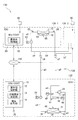
- FIG. 2 is a refrigerant system diagram of the air conditioner 130 described above.
- the air conditioner 130 includes the two indoor units 136-1 and 136-2, the single outdoor unit 132, and the refrigerant pipe 134 that connects these to each other. Since the two indoor units 136-1 and 136-2 have the same configuration, both may be collectively referred to as "indoor unit 136" hereinafter.
- Each indoor unit 136 sets an indoor air volume (a sudden wind, a strong wind, a weak wind, etc.), a target indoor temperature, etc. according to a signal input from the remote controller 90.
- the outdoor unit 132 includes an outdoor unit controller 10 (a computer, a connection relationship determination device) denoted by “ODU CONT”, a compressor 32, a four-way valve 34, an outdoor heat exchanger 36, and an outdoor expansion valve 38. , Are provided.
- the compressor 32 has a function of compressing the refrigerant flowing in through the four-way valve 34.
- a suction side temperature sensor 41 for detecting the temperature of the refrigerant sucked into the compressor 32 and a suction side pressure sensor 45 for detecting the pressure of the refrigerant sucked into the compressor 32 are provided. is set up.
- a discharge side temperature sensor 42 that detects the temperature of the refrigerant discharged from the compressor 32, and a discharge side pressure sensor 46 (pressure sensor) that detects the pressure of the refrigerant discharged from the compressor 32. Have been installed.
- the four-way valve 34 has a function of switching the direction of the refrigerant supplied to the indoor unit 136 between the cooling operation and the heating operation. During the cooling operation, the four-way valve 34 is switched so as to connect the pipes a2 and a3 and the pipes a1 and a6 along the path indicated by the solid line.
- the high temperature and high pressure refrigerant discharged from the compressor 32 is cooled by the outdoor heat exchanger 36.
- the cooled refrigerant is supplied to the indoor units 136-1 and 136-2 through the pipe a4, the outdoor expansion valve 38, the pipe a5, the indoor liquid side connection portion d9, and the pipes a9 and b9 in this order.
- the refrigerant is decompressed by the indoor expansion valve 62 (expansion valve).
- the four-way valve 34 is switched to connect the pipes a2 and a6 and to connect the pipes a1 and a3 along the path of the broken line.
- the high-temperature and high-pressure refrigerant discharged from the compressor 32 is supplied to the indoor units 136-1 and 136-2 via the pipes a2 and a6, the indoor gas side connection portion d7, and the pipes a7 and b7.
- the outdoor fan 48 blows air to the outdoor heat exchanger 36.
- the outdoor heat exchanger 36 is a heat exchanger that exchanges heat between the air sent from the outdoor fan 48 and the refrigerant, and is connected to the compressor 32 via the four-way valve 34.
- the outdoor unit 132 has an outdoor heat exchanger suction temperature sensor 51 for detecting the temperature of the air flowing into the outdoor heat exchanger 36, and an outdoor heat exchanger for detecting the temperature of the gas-side refrigerant of the outdoor heat exchanger 36.
- a refrigerant gas temperature sensor 53 and an outdoor heat exchanger refrigerant liquid temperature sensor 55 for detecting the temperature of the liquid side refrigerant of the outdoor heat exchanger 36 are mounted.
- the outdoor expansion valve 38 is inserted between the pipes a4 and a5, and has a function of adjusting the flow rate of the refrigerant flowing through the pipes a4 and a5 and reducing the pressure of the refrigerant on the secondary side of the outdoor expansion valve 38.
- the outdoor unit controller 10 includes hardware such as a CPU (Central Processing Unit), a RAM (Random Access Memory), and a ROM (Read Only Memory) as a general computer.
- the ROM executes the CPU.
- the control program, various data, etc. are stored.
- FIG. 2 the inside of the outdoor unit controller 10 shows the functions realized by a control program or the like as blocks. That is, the outdoor unit control unit 10 includes an outdoor unit starting unit 12 (outdoor unit starting unit), a connection relationship determination unit 14 (connection relationship determination unit), and an opening adjustment unit 16. Further, a setting start operation unit 35 is attached to the outdoor unit control unit 10. When detecting the operation of the setting start operation unit 35, the outdoor unit control unit 10 activates a setting processing routine (FIG. 3) described later.
- a setting processing routine FIG. 3
- the indoor unit 136-1 includes an indoor unit controller 80 (computer, connection relationship determination device) denoted by “IDU CONT”, an indoor expansion valve 62, an indoor heat exchanger 64, and an indoor fan 66. ing.
- the indoor fan 66 blows air to the indoor heat exchanger 64.
- the indoor unit controller 80 includes hardware such as a CPU, a RAM, and a ROM as a general computer, similarly to the outdoor unit controller 10 described above. Each part of the machine 136 is controlled.
- the inside of the indoor unit control unit 80 shows the functions realized by a control program or the like as blocks. That is, the indoor unit controller 80 includes the expansion valve controller 82.
- the indoor expansion valve 62 has a function of being inserted between the pipes a8 and a9, adjusting the flow rate of the refrigerant flowing through the pipes a8 and a9, and reducing the pressure of the refrigerant on the secondary side of the indoor expansion valve 62.
- the indoor heat exchanger 64 is a heat exchanger that performs heat exchange between the indoor air sent from the indoor fan 66 and the refrigerant, and is connected to the indoor expansion valve 62 via the pipe a8.
- the indoor unit 136 includes the indoor heat exchanger intake air temperature sensor 70, the indoor heat exchanger outlet air temperature sensor 72, the indoor heat exchanger refrigerant liquid temperature sensor 25, and the indoor heat exchanger refrigerant gas temperature sensor 26 ( Temperature sensor).
- the indoor heat exchanger intake air temperature sensor 70 detects the temperature of the air drawn by the indoor fan 66.
- the indoor heat exchanger blown air temperature sensor 72 detects the temperature of the air blown out by the indoor heat exchanger 64.
- the indoor heat exchanger refrigerant liquid temperature sensor 25 and the indoor heat exchanger refrigerant gas temperature sensor 26 are respectively provided at the connection points between the indoor heat exchanger 64 and the pipes a7 and a8, and the refrigerant flowing through these points is Detect the temperature.
- the above-mentioned pipes a5, a6, a7, a9, b7, b9, the indoor gas side connection part d7 and the indoor liquid side connection part d9 correspond to the refrigerant pipe 134 of the air conditioner 130.
- the outdoor unit control unit 10 and the indoor unit control unit 80 perform bidirectional communication via the communication network 150. However, as will be described later in detail, in the initial state of the air conditioning system S, the outdoor unit controller 10 may communicate with the outdoor unit or the indoor unit in another air conditioner via the communication network 150. .. Similarly, in the initial state or the like of the air conditioning system S, the indoor unit control unit 80 may communicate with the outdoor unit in another air conditioner via the communication network 150.
- the configuration of the air conditioner 130 has been described in detail above, the other air conditioners 110, 120, 140 (see FIG. 1) are configured similarly to the air conditioner 130, except that the number of indoor units is different. ing.
- FIG. 3 is a flowchart of the setting processing routine.
- each outdoor unit is provided with the setting start operation unit 35 (see FIG. 2). Then, when a worker operates the setting start operation unit 35 in any of the outdoor units, this routine is started in the outdoor unit control unit 10 of the outdoor unit.
- the outdoor unit executing this routine is called a master outdoor unit, and the outdoor units other than the master outdoor unit are called slave outdoor units.
- the air conditioning system S is installed or repaired, the connection relationship between each outdoor unit and each indoor unit may become unclear. In such a case, it is preferable to execute this routine to clarify the connection relationship.
- a predetermined initial setting is performed in the master outdoor unit.
- the outdoor unit control unit 10 of the master outdoor unit acquires the network IDs of all the outdoor units and the indoor units connected to the communication network 150 in step S2.
- the outdoor unit control unit 10 of the master outdoor unit that has started this routine collects information from each outdoor unit and each indoor unit via the communication network 150, and at the same time, each outdoor unit and each indoor unit. Control the machine.
- the outdoor unit starting unit 12 (see FIG. 2) of the master outdoor unit selects any two outdoor units.
- the two selected outdoor units are called "target outdoor units".
- the target outdoor unit may be a master outdoor unit or a slave outdoor unit.
- the outdoor unit starting unit 12 of the master outdoor unit stops the refrigeration cycle of all the outdoor units.
- the outdoor unit starting unit 12 puts all the indoor units into a stopped state and stores the measured temperature of the indoor heat exchanger refrigerant gas temperature sensor 26 for each indoor unit. Output the command to.
- the indoor unit controller 80 of each indoor unit acquires and stores the temperature measured by the indoor heat exchanger refrigerant gas temperature sensor 26 based on this command.
- the measured temperature stored here is called a measured temperature initial value.
- the outdoor unit starting unit 12 of the master outdoor unit outputs a command to all the indoor units to open the indoor expansion valve 62.
- the indoor unit controller 80 of each indoor unit opens the indoor expansion valve 62 based on this command.
- the outdoor unit starting unit 12 selects one of the two outdoor units previously selected in step S4 (hereinafter referred to as a cooling target outdoor unit (first target outdoor unit)).
- the air-conditioning operation is started at (called), and the heating operation is started at the other (hereinafter, referred to as a heating-target outdoor unit (second target outdoor unit)).
- the outdoor heat exchanger 36 functions as a condenser in the cooling target outdoor unit, and the outdoor heat exchanger 36 functions as an evaporator in the heating target outdoor unit.
- the indoor unit control unit 80 of each indoor unit monitors the temperature measured by the indoor heat exchanger refrigerant gas temperature sensor 26 after setting the indoor expansion valve 62 to the open state in step S10 described above. Then, when a temperature difference of a predetermined value or more occurs between the measured temperature and the measured temperature initial value, the indoor unit control unit 80 issues a "temperature change report" to that effect to the outdoor unit control unit of the master outdoor unit. Send to 10.
- a temperature change report There are two types of temperature change reports, a temperature increase change report and a temperature decrease change report. The former is a report showing that the measured temperature has increased with respect to the initial value of the measured temperature, and the latter is a report showing that it has decreased.
- the expansion valve control unit 82 (see FIG. 2) of the indoor unit control unit 80 sets the indoor expansion valve 62 in the indoor unit to the closed state.
- connection relationship determination unit 14 (see FIG. 2) of the master outdoor unit determines whether or not the above-mentioned temperature change report is received from any of the indoor units. To do. If “Yes” is determined here, the process proceeds to step S ⁇ b>16, and the connection relationship determination unit 14 performs the numbering on the indoor unit that has transmitted the temperature change report and the setting of the opening correction value.
- the numbering refers to associating the indoor unit with the cooling target outdoor unit or the heating target outdoor unit and assigning a serial number.
- step S16 when the master outdoor unit receives the temperature rise change report, the indoor unit that transmitted the report is associated with the outdoor unit to be heated. Conversely, when the master outdoor unit receives the temperature decrease change report, the indoor unit that transmitted the report is associated with the cooling target outdoor unit. Then, ascending order serial numbers “1”, “2”, “3”,... Are assigned to the indoor units in the order of being associated with the heating target outdoor unit and the cooling target outdoor unit, respectively. .. The “setting of the opening degree correction value” executed in step S16 will be described later.
- step S18 the connection relationship determination unit 14 of the master outdoor unit determines whether or not the pressure increase is detected in any of the target outdoor units. More specifically, when the pressure detected by the discharge-side pressure sensor 46 exceeds a predetermined pressure threshold, it may be determined that “a pressure increase has been detected”. Alternatively, when the inclination of the pressure detected by the discharge-side pressure sensor 46 (the time derivative of the detected pressure) exceeds a predetermined value, it may be determined that "a pressure increase has been detected”.
- the expansion valve control unit 82 sets the indoor expansion valve 62 to the closed state.
- the indoor expansion valve 62 is closed in all the indoor units connected to a certain target outdoor unit, the refrigerant path is blocked, and therefore the measured pressure of the discharge side pressure sensor 46 of the target outdoor unit becomes large. ..
- the pressure increase is detected in any of the target outdoor units, all the indoor units connected to the target outdoor unit are already numbered.
- step S18 If “No” is determined in step S18, the process returns to step S14, and the operations of steps S14 to S18 described above are repeated. On the other hand, if "Yes” is determined in step S18, the process proceeds to step S20.
- step S20 the connection relationship determination unit 14 of the master outdoor unit stops the corresponding outdoor unit, that is, the target outdoor unit that has detected the pressure increase. Then, the correspondence relationship between the target outdoor unit and the indoor unit already numbered for the target outdoor unit is confirmed.
- connection relationship determination unit 14 of the master outdoor unit transmits the network ID of each corresponding indoor unit, the serial number, and the opening correction value to the target outdoor unit.
- the target outdoor unit stores the transmitted data. These data are used to control each indoor unit when the target outdoor unit later executes a normal operation (for example, a cooling operation, a dehumidifying operation, a heating operation, etc.).
- step S22 it is determined whether or not the two outdoor units, that is, both the heating target outdoor unit and the cooling target outdoor unit have been stopped. If it is determined “No” here, the process returns to step S14, and the operations of steps S14 to S22 are continued for the target outdoor unit in operation. When the process proceeds to step S22 after both target outdoor units are stopped, it is determined to be "Yes” here, and the process proceeds to step S24.
- step S24 it is determined whether or not the correspondence with all the outdoor units connected to the communication network 150 has been established, that is, whether the process of step S20 has been executed. If "No" is determined here, the process returns to step S4, and two target outdoor units are selected from the remaining outdoor units for which the correspondence relationship is not determined, and steps S4 to S24 are performed for these. The process of is repeated. When only one remaining outdoor unit is available, only one of the cooling target outdoor unit and the heating target outdoor unit may be selected in step S4. In this way, when the correspondence relationship between all the outdoor units connected to the communication network 150 and the indoor units is determined, the processing of this routine ends.
- step S4 of FIG. 2 it is assumed that the outdoor unit 112 is selected as the cooling target outdoor unit and the outdoor unit 122 is selected as the heating target outdoor unit. Then, in the indoor units 116-1 to 116-4, the cooling operation is performed, so that the temperature measured by the indoor heat exchanger refrigerant gas temperature sensor 26 decreases.
- the temperature decrease change report is transmitted from the indoor unit to the outdoor unit 132 that is the master outdoor unit.
- the connection relationship determination unit 14 of the outdoor unit 132 which is the master outdoor unit, associates the indoor unit with the outdoor unit 112, which is the cooling target outdoor unit, and assigns the serial number in ascending order. It is given (step S16 in FIG. 3).
- the timing at which the indoor unit outputs the temperature change report tends to be earlier as the refrigerant pipe distance to the outdoor unit is shorter. In the example shown in FIG.
- the indoor units 116-1 to 116-4 have a short refrigerant pipe distance in the order of their codes. Then, the serial numbers "1" to "4" are sequentially assigned to the indoor units 116-1 to 116-4. Then, when all the indoor expansion valves 62 of the indoor units 116-1 to 116-4 are closed, the pressure of the discharge side pressure sensor 46 in the outdoor unit 112 rises, so that the processes of steps S18 and S20 of FIG. The outdoor unit 112, which is the outdoor unit to be cooled, is stopped.
- the indoor units 126-1 to 126-5 perform the heating operation, the temperature measured by the indoor heat exchanger refrigerant gas temperature sensor 26 rises.
- the indoor unit 126-5 arranged on the third floor has a smaller refrigerant pipe distance from the outdoor unit 122 than the indoor units 126-1 to 126-4 arranged on the fourth floor. Long time.
- the serial numbers “1” to “5” are sequentially assigned to the indoor units 126-1 to 126-5.
- the outdoor unit 122 which is the heating target outdoor unit, is stopped by the processing of steps S18 and S20 of FIG.
- step S22 of FIG. When both the outdoor units 112 and 122 that are the target outdoor units are stopped, it is determined as “Yes” in step S22 of FIG. At this point in time, there are outdoor units 132 and 142 for which the correspondence relationship has not yet been determined, so it is determined as “No” in step S24. Then, when the process proceeds to step S4 again, the outdoor units 132 and 142 are selected as the cooling target outdoor unit and the heating target outdoor unit, and the outdoor units 132 and 142 are set to the outdoor units 132 and 142 as in the case of the outdoor units 112 and 122 described above. Then, the association with the indoor unit is performed. As a result, the correspondence relationship between all the outdoor units and the indoor units shown in FIG. 1 is established.
- the opening correction value set in step S16 of FIG. 3 will be described.
- the outdoor unit commands the indoor unit to open the indoor expansion valve 62 according to the set temperature set by the user, the indoor temperature of the air-conditioned room, and the like.
- the refrigerant flow rate of the latter indoor unit decreases.
- the air conditioning capacity tends to decrease.
- the opening correction value is set for each indoor unit in step S16 described above. That is, in the present embodiment, the master outdoor unit measures, for each indoor unit, the elapsed time from the time when the target outdoor unit is activated (step S12) to the time when the temperature change report is received (step S16). There is. Then, a value that becomes larger as the indoor unit has a longer elapsed time is set to the target outdoor unit as the opening correction value of the indoor unit.
- the opening adjustment unit 16 of each outdoor unit adjusts the set temperature of each indoor unit or the indoor temperature of the air-conditioned room. Accordingly, the opening reference value of the indoor expansion valve 62 of each indoor unit is calculated.
- the opening reference value is a value indicating the opening of the indoor expansion valve 62 when it is assumed that the refrigerant pipe distance to the indoor unit is sufficiently short.
- the opening adjustment unit 16 of the outdoor unit multiplies the opening reference value and the opening correction value of each indoor unit to calculate the actually applied opening, and the opening adjustment is performed for each indoor unit. Command the degree.
- the refrigerant piping distance of the indoor unit 126-5 is longer than the refrigerant piping distance of the indoor unit 126-1.
- the indoor units 126-1 and 126-5 are the same model, and the set temperatures of both are the same and the indoor temperature of the air-conditioned room is also the same.
- the opening adjustment unit 16 of the outdoor unit 122 sets the opening degree of the indoor expansion valve 62 in the indoor unit 126-5 to the opening degree of the indoor expansion valve 62 in the indoor unit 126-1. Set to be larger than degrees. As a result, it is possible to compensate for variations in air conditioning capacity due to differences in refrigerant piping distance and the like.
- the connection relation determination device (10, 80) of the refrigeration system includes the outdoor unit starter (12) that starts the refrigeration cycle of the target outdoor unit that is at least one outdoor unit, and the outdoor unit.
- the expansion valves (62) in the plurality of indoor units are set to the open state, and when the refrigerant-related temperature changes in any of the indoor units, the expansion valve (62) of the corresponding indoor unit is opened.
- the expansion valve control unit (82) set to the closed state, the target outdoor unit and the indoor unit with the expansion valve (62) closed when a predetermined change occurs in the refrigerant pressure in the target outdoor unit.
- a connection relation determination unit (14) that determines that the connection is established.
- the outdoor unit starting unit (12) includes the first target outdoor unit that causes the corresponding outdoor heat exchanger (36) to function as a condenser as the target outdoor unit, and the corresponding outdoor heat.
- a second target outdoor unit that causes the exchanger (36) to function as an evaporator is started so as to have a period in which the second target outdoor unit simultaneously operates, and the connection relationship determination unit (14) causes the refrigerant-related temperature to increase. It is determined that the indoor unit that has changed to 1 is connected to the first target outdoor unit, and that the indoor unit that has changed in the direction in which the refrigerant-related temperature decreases is connected to the second target outdoor unit. By thus providing the period in which the first and second target outdoor units are simultaneously operated, the connection relationship between the outdoor unit and the indoor unit can be determined more quickly.
- an opening adjustment unit (16) for controlling each expansion valve (62) so as to increase the opening when opening the expansion valve (62) is further provided.
- the connection relationship determination device (10, 80) of the refrigeration system further includes a setting start operation unit (35) operated by a worker, and operates the setting start operation unit (35).
- a setting start operation unit (35) operated by a worker, and operates the setting start operation unit (35).
- the connection relationship between the outdoor unit and the indoor unit can be determined not only when the refrigeration system (S) is installed, but also when it is repaired or maintained, or at any other time.
- the present invention is not limited to the above-described embodiment, and various modifications can be made.
- the above-described embodiments have been described as examples for easily understanding the present invention, and are not necessarily limited to those including all the configurations described. Further, another configuration may be added to the configuration of the above-described embodiment, and a part of the configuration may be replaced with another configuration. Further, the control lines and information lines shown in the figure are those considered necessary for the explanation, and not all the control lines and information lines necessary for the product are shown. In practice, it may be considered that almost all configurations are connected to each other.
- the possible modifications to the above embodiment are, for example, as follows.
- the outdoor unit controller 10 of the master outdoor unit realizes the functions of the outdoor unit starter 12 and the connection relationship determiner 14, and the indoor unit controller 80 of each indoor unit is the expansion valve controller. 82 functions have been realized.
- the outdoor unit controller 10 of the master outdoor unit may realize all of these functions 12, 14, 82.
- the indoor unit control unit 80 of each indoor unit periodically transmits the temperature measured by the indoor heat exchanger refrigerant gas temperature sensor 26 to the master outdoor unit, and when the command is received from the master outdoor unit, the indoor unit is for indoor use.
- the expansion valve 62 may be set to the closed state. Further, the outdoor unit control unit 10 of the master outdoor unit may transmit a command to close the indoor expansion valve 62 to each indoor unit based on the measured temperature received from each indoor unit.
- the functions 12, 14, and 82 described above may be realized by various computers other than the outdoor unit controller 10 and the indoor unit controller 80.
- the building 100 in FIG. 1 may be provided with an in-building management device (not shown) that comprehensively manages the air conditioners 110 to 140, and the functions 12, 14, and 82 may be realized by this in-building management device.
- the communication network 150 may be connected to a wide area network such as the Internet, a management server may be connected to the wide area network, and the functions 12, 14, and 82 may be realized by this management server.
- the program according to the flowchart shown in FIG. 3 is stored in a storage medium or transmitted. It may be distributed via the road.
- the processing shown in FIG. 3 has been described as software processing using a program in the above embodiment, but a part or all of the processing is an ASIC (Application Specific Integrated Circuit) or an FPGA. It may be replaced with a hardware process using (Field Programmable Gate Array) or the like.
- ASIC Application Specific Integrated Circuit
- FPGA Field Programmable Gate Array
- the present invention may be applied not only to the air conditioning system S of the above embodiment, but also to various refrigeration systems.
- Outdoor unit controller (computer, connection relationship determination device) 12 Outdoor unit starting part (outdoor unit starting means) 14 Connection Relation Judgment Unit (Connection Relation Judgment Means) 16 Opening degree adjusting unit 25 Indoor heat exchanger refrigerant liquid temperature sensor 26 Indoor heat exchanger refrigerant gas temperature sensor (temperature sensor) 32 compressor 35 setting start operation part 36 outdoor heat exchanger 46 discharge side pressure sensor (pressure sensor) 62 Indoor expansion valve (expansion valve) 64 Indoor heat exchanger 80 Indoor unit control unit (computer, connection relationship determination device) 82 Expansion valve control unit 110, 120, 130, 140 Air conditioner 112, 122, 132, 142 Outdoor unit 116-1 to 116-4, 126-1 to 126-5, 136-1, 136-2, 146- 1-146-4 Indoor unit S Air conditioning system (refrigeration system)
Landscapes
- Engineering & Computer Science (AREA)
- Mechanical Engineering (AREA)
- General Engineering & Computer Science (AREA)
- Physics & Mathematics (AREA)
- Thermal Sciences (AREA)
- Chemical & Material Sciences (AREA)
- Combustion & Propulsion (AREA)
- Air Conditioning Control Device (AREA)
Abstract
冷凍システムにおいて、室外機および室内機の接続関係を迅速・確実に判定できるようにする。そのため、冷凍システムの接続関係判定装置(10,80)は、少なくとも1台の室外機である対象室外機の冷凍サイクルを始動させる室外機始動部(12)と、対象室外機が始動する際に、複数の室内機における膨張弁(62)を開状態に設定し、何れかの室内機において冷媒関係温度に変化が生じると、対応する室内機の膨張弁(62)を閉状態に設定する膨張弁制御部(82)と、対象室外機における冷媒圧力に所定の変化が生じた際に、対象室外機と、膨張弁(62)が閉状態にされた室内機とが接続されている旨を判定する接続関係判定部(14)と、を備える。
Description
本発明は、冷凍システムの接続関係判定装置、冷凍システムおよびプログラムに関する。
大型のビルディング等に設置される空気調和システムは、複数の空気調和機を備えることが多い。ここで、各空気調和機は、相互に冷媒配管で接続された少なくとも1台の室外機と、少なくとも1台の室内機と、を備えている。そして、複数の空気調和機に属する室外機と室内機とは、共通のネットワークに接続されることが多い。すなわち、室外機は、物理的には全ての室内機と通信可能な状態になる。このネットワークにおいて、各室外機および各室内機には、ユニークな識別番号が付与されている。そして、各室外機は、この識別番号によって、自機に接続されている室内機を認識することができる。しかし、何れかの室外機において、接続されている室内機の識別番号を誤って設定すると、空気調和システムが正常に動作しなくなる。そこで、各室外機に接続されている室内機を自動的に認識する技術が知られている。
その一例として、下記特許文献1の請求項5には、「圧縮機、室外熱交換器、四方弁、温度センサ及び室外制御手段を備える室外機に、電子膨張弁、室内熱交換器、送風ファン、温度センサ及び室内制御手段とを備える室内機を接続して同一冷媒系統を構成する分離型の空気調和機を複数配設し、前記各室外制御手段及び室内制御手段に接続される信号線を同一の通信線を介して接続してなる空気調和システムにおいて、前記室外機の任意の1台の室外制御手段は、同室外制御手段に組み込まれる冷媒系統判定プログラムが起動されると、前記空気調和システムを構成する全ての室外機及び室内機の運転を停止させた後、当該室外機の外気温度を検出し、同外気温度に基づいて冷房運転モードを選択し、当該室外機及び前記室内機を冷房運転モードとして圧縮機の運転を開始して冷媒の供給を開始した場合は、前記各室内熱交換器の冷房時冷媒流入温度(Tin)と前記低圧飽和温度(Te)を検出して比較し、一定時間内に、その差(Tin-Te)が所定の温度差(α)以下、即ち(Tin<Te+α)とならなかった室内機の冷媒系統が前記室外機の冷媒系統に対応しないと判定し、前記一定時間内に、所定の温度差(α)以下、即ち(Tin<Te+α)となった場合、その室内機の冷媒系統が前記室外機の冷媒系統に対応すると判定し、同室外機の冷媒系統に対応すると判定された室内機に対して冷媒系統アドレスを設定するようにしたことを特徴とする空気調和機の冷媒系統アドレス設定方法。」と記載されている。
しかし、上記特許文献1の技術では、冷媒配管が長い場合等には、運転中の室外機に接続されているにもかかわらず、一定時間内に温度差(α)が現れない室内機が生じ、冷媒配管の接続関係を誤判定する可能性が生じる。誤判定を避けるためには、上記一定時間を長くせざるを得なくなり、判定時間が長くなるという問題があった。また、空気調和システム内では、複数の室外機を同時に動作させることはできず1台ずつ動作させるため、これによって判定時間が一層長くなるという問題もあった。
この発明は上述した事情に鑑みてなされたものであり、室外機および室内機の接続関係を迅速、確実に判定できる冷凍システムの接続関係判定装置、冷凍システムおよびプログラムを提供することを目的とする。
この発明は上述した事情に鑑みてなされたものであり、室外機および室内機の接続関係を迅速、確実に判定できる冷凍システムの接続関係判定装置、冷凍システムおよびプログラムを提供することを目的とする。
上記課題を解決するため本発明の冷凍システムの接続関係判定装置は、室内熱交換器と、前記室内熱交換器に流通する冷媒の流通経路を開閉する膨張弁と、冷媒温度の変化に応じて変化する冷媒関係温度を測定する温度センサと、を各々が備える複数の室内機と、室外熱交換器と、前記冷媒を圧縮して対応する前記室内機に供給する圧縮機と、冷媒圧力を検出する圧力センサと、を各々が備える複数の室外機と、を備える冷凍システムに適用され、少なくとも1台の前記室外機である対象室外機の冷凍サイクルを始動させる室外機始動部と、前記対象室外機が始動する際に、複数の前記室内機における前記膨張弁を開状態に設定し、何れかの前記室内機において前記冷媒関係温度に変化が生じると、対応する前記室内機の前記膨張弁を閉状態に設定する膨張弁制御部と、前記対象室外機における前記冷媒圧力に所定の変化が生じた際に、前記対象室外機と、前記膨張弁が閉状態にされた前記室内機とが接続されている旨を判定する接続関係判定部と、を備えることを特徴とする。
本発明によれば、室外機および室内機の接続関係を迅速、確実に判定できる。
〈実施形態の構成〉
(全体構成)
図1は、本発明の一実施形態による空気調和システムS(冷凍システム)のブロック図である。この空気調和システムSは、4階建てのビルディング100に設置されている。
図1において空気調和システムSは、4組の空気調和機110,120,130,140を備え、各空気調和機は、一台の室外機(図1においてODUと記す)と、複数台の室内機(同、IDUと記す)と、を備えている。すなわち、空気調和機110は、室外機112と、室内機116-1~116-4と、これらを相互に接続する冷媒配管114と、を備えている。
(全体構成)
図1は、本発明の一実施形態による空気調和システムS(冷凍システム)のブロック図である。この空気調和システムSは、4階建てのビルディング100に設置されている。
図1において空気調和システムSは、4組の空気調和機110,120,130,140を備え、各空気調和機は、一台の室外機(図1においてODUと記す)と、複数台の室内機(同、IDUと記す)と、を備えている。すなわち、空気調和機110は、室外機112と、室内機116-1~116-4と、これらを相互に接続する冷媒配管114と、を備えている。
同様に、空気調和機120は、室外機122と、室内機126-1~126-5と、これらを相互に接続する冷媒配管124と、を備えている。同様に、空気調和機130は、室外機132と、室内機136-1,136-2と、これらを相互に接続する冷媒配管134と、を備えている。同様に、空気調和機140は、室外機142と、室内機146-1~146-4と、これらを相互に接続する冷媒配管144と、を備えている。
また、空気調和システムSは、上述した各室外機および室内機を相互に接続する通信ネットワーク150を備えている。この通信ネットワーク150において、各室外機および室内機には、一意のネットワークIDが付与されている。これにより、各室外機および室内機は、物理的には他の全ての室外機および室内機と通信可能な状態になっている。室外機112,122,132,142は、ビルディング100の屋上に設置されている。また、室内機146-1~146-4は、例えばビルディング100の1階に、室内機116-1~116-4は2階に、室内機136-1,136-2,126-5は3階に、室内機126-1~126-4は4階に、それぞれ設置されている。
図2は、上述した空気調和機130の冷媒系統図である。空気調和機130は、上述したように、2台の室内機136-1,136-2と、一台の室外機132と、これらを相互に接続する冷媒配管134と、を備えている。2台の室内機136-1,136-2は、同様に構成されているため、以下、両者を総称して「室内機136」と記することがある。各室内機136は、リモコン90から入力される信号に応じて室内風量(急風、強風、弱風等)、目標室内温度等を設定する。
(室外機132)
室外機132は、「ODU CONT」と表記する室外機制御部10(コンピュータ、接続関係判定装置)と、圧縮機32と、四方弁34と、室外熱交換器36と、室外用膨張弁38と、を備えている。圧縮機32は、四方弁34を介して流入する冷媒を圧縮する機能を有している。
室外機132は、「ODU CONT」と表記する室外機制御部10(コンピュータ、接続関係判定装置)と、圧縮機32と、四方弁34と、室外熱交換器36と、室外用膨張弁38と、を備えている。圧縮機32は、四方弁34を介して流入する冷媒を圧縮する機能を有している。
図2に示す配管a1には、圧縮機32に吸入される冷媒の温度を検出する吸入側温度センサ41と、圧縮機32に吸入される冷媒の圧力を検出する吸入側圧力センサ45と、が設置されている。また、配管a2には、圧縮機32から吐出される冷媒の温度を検出する吐出側温度センサ42と、圧縮機32から吐出される冷媒の圧力を検出する吐出側圧力センサ46(圧力センサ)と、が設置されている。
四方弁34は、冷房運転と暖房運転とで室内機136に供給する冷媒の向きを切り替える機能を有している。冷房運転時には、四方弁34は、実線の経路に沿って、配管a2,a3を接続するとともに配管a1,a6を接続するように切り替えられる。この場合、圧縮機32から吐出された高温高圧の冷媒は、室外熱交換器36によって冷却される。冷却された冷媒は、配管a4、室外用膨張弁38、配管a5、室内液側接続部d9、配管a9,b9を順次介して、室内機136-1,136-2に供給される。これら室内機においては、室内用膨張弁62(膨張弁)で冷媒が減圧される。
また、暖房運転時には、四方弁34は、破線の経路に沿って、配管a2,a6を接続するとともに、配管a1,a3を接続するように切り替えられる。この場合、圧縮機32から吐出された高温高圧の冷媒は、配管a2,a6、室内ガス側接続部d7、配管a7,b7を介して、室内機136-1,136-2に供給される。室外ファン48は、室外熱交換器36に対して送風する。
室外熱交換器36は、室外ファン48から送られてくる空気と、冷媒との熱交換を行う熱交換器であり、四方弁34を介して圧縮機32に接続されている。また、室外機132には、室外熱交換器36に流入する空気の温度を検出する室外熱交換器吸込み温度センサ51と、室外熱交換器36のガス側冷媒の温度を検出する室外熱交換器冷媒ガス温度センサ53と、室外熱交換器36の液側冷媒の温度を検出する室外熱交換器冷媒液温度センサ55と、が装着されている。室外用膨張弁38は、配管a4,a5の間に挿入されており、配管a4,a5を流通する冷媒の流量を調整するとともに、室外用膨張弁38の二次側の冷媒を減圧する機能を有している。
室外機制御部10は、CPU(Central Processing Unit)、RAM(Random Access Memory)、ROM(Read Only Memory)等、一般的なコンピュータとしてのハードウエアを備えており、ROMには、CPUによって実行される制御プログラムや、各種データ等が格納されている。図2において室外機制御部10の内部は、制御プログラム等によって実現される機能を、ブロックとして示している。すなわち、室外機制御部10は、室外機始動部12(室外機始動手段)と、接続関係判定部14(接続関係判定手段)と、開度調整部16と、を備えている。また、室外機制御部10には、設定開始操作部35が装着されている。室外機制御部10は、設定開始操作部35の操作を検出すると、後述する設定処理ルーチン(図3)を起動する。
(室内機136)
室内機136-1は、「IDU CONT」と表記する室内機制御部80(コンピュータ、接続関係判定装置)と、室内用膨張弁62と、室内熱交換器64と、室内ファン66と、を備えている。室内ファン66は室内熱交換器64に対して送風する。室内機制御部80は、上述した室外機制御部10と同様に、CPU、RAM、ROM等、一般的なコンピュータとしてのハードウエアを備えており、室外機制御部10からの指令に応じて室内機136の各部を制御する。図2において室内機制御部80の内部は、制御プログラム等によって実現される機能を、ブロックとして示している。すなわち、室内機制御部80は、膨張弁制御部82を備えている。
室内機136-1は、「IDU CONT」と表記する室内機制御部80(コンピュータ、接続関係判定装置)と、室内用膨張弁62と、室内熱交換器64と、室内ファン66と、を備えている。室内ファン66は室内熱交換器64に対して送風する。室内機制御部80は、上述した室外機制御部10と同様に、CPU、RAM、ROM等、一般的なコンピュータとしてのハードウエアを備えており、室外機制御部10からの指令に応じて室内機136の各部を制御する。図2において室内機制御部80の内部は、制御プログラム等によって実現される機能を、ブロックとして示している。すなわち、室内機制御部80は、膨張弁制御部82を備えている。
室内用膨張弁62は、配管a8,a9の間に挿入され、配管a8,a9を流通する冷媒の流量を調整するとともに、室内用膨張弁62の二次側の冷媒を減圧する機能を有している。室内熱交換器64は、室内ファン66から送られてくる室内空気と冷媒との熱交換を行う熱交換器であり、配管a8を介して室内用膨張弁62に接続されている。
また、室内機136は、室内熱交換器吸込み空気温度センサ70と、室内熱交換器吹出し空気温度センサ72と、室内熱交換器冷媒液温度センサ25と、室内熱交換器冷媒ガス温度センサ26(温度センサ)と、を備えている。
ここで、室内熱交換器吸込み空気温度センサ70は、室内ファン66が吸い込む空気の温度を検出する。また、室内熱交換器吹出し空気温度センサ72は、室内熱交換器64が吹き出す空気の温度を検出する。
ここで、室内熱交換器吸込み空気温度センサ70は、室内ファン66が吸い込む空気の温度を検出する。また、室内熱交換器吹出し空気温度センサ72は、室内熱交換器64が吹き出す空気の温度を検出する。
また、室内熱交換器冷媒液温度センサ25、室内熱交換器冷媒ガス温度センサ26は、室内熱交換器64と、配管a7,a8との接続箇所にそれぞれ設けられ、その箇所を流通する冷媒の温度を検出する。上述した配管a5,a6,a7,a9,b7,b9、室内ガス側接続部d7および室内液側接続部d9は、空気調和機130の冷媒配管134に対応する。
室外機制御部10と、室内機制御部80とは、通信ネットワーク150を介して双方向通信を行う。但し、詳細は後述するが、空気調和システムSの初期状態等においては、室外機制御部10は、通信ネットワーク150を介して、他の空気調和機における室外機または室内機と通信することもある。同様に、空気調和システムSの初期状態等において、室内機制御部80は、通信ネットワーク150を介して、他の空気調和機における室外機と通信することもある。
以上、空気調和機130の構成について詳述したが、室内機の台数が異なる点を除いて、他の空気調和機110,120,140(図1参照)も空気調和機130と同様に構成されている。
以上、空気調和機130の構成について詳述したが、室内機の台数が異なる点を除いて、他の空気調和機110,120,140(図1参照)も空気調和機130と同様に構成されている。
〈実施形態の動作〉
図3は、設定処理ルーチンのフローチャートである。
上述したように、各室外機には、設定開始操作部35(図2参照)が備えられている。そして、何れかの室外機において作業員が設定開始操作部35を操作すると、当該室外機の室外機制御部10において、本ルーチンが起動される。ここで、本ルーチンを実行している室外機をマスタ室外機と呼び、マスタ室外機以外の室外機をスレーブ室外機と呼ぶ。空気調和システムSの設置時や、改修時等においては、各室外機と各室内機との接続関係が不明確になることがある。そのような場合に、本ルーチンを実行し、接続関係を明確にすることが好ましい。
図3は、設定処理ルーチンのフローチャートである。
上述したように、各室外機には、設定開始操作部35(図2参照)が備えられている。そして、何れかの室外機において作業員が設定開始操作部35を操作すると、当該室外機の室外機制御部10において、本ルーチンが起動される。ここで、本ルーチンを実行している室外機をマスタ室外機と呼び、マスタ室外機以外の室外機をスレーブ室外機と呼ぶ。空気調和システムSの設置時や、改修時等においては、各室外機と各室内機との接続関係が不明確になることがある。そのような場合に、本ルーチンを実行し、接続関係を明確にすることが好ましい。
図3において処理がステップS2に進むと、マスタ室外機において所定の初期設定が行われる。例えば、マスタ室外機の室外機制御部10は、ステップS2において、通信ネットワーク150に接続されている全ての室外機および室内機のネットワークIDを取得する。このステップS2以降、本ルーチンを起動しているマスタ室外機の室外機制御部10は、通信ネットワーク150を介して、各室外機および各室内機から情報を収集するとともに、各室外機および各室内機を制御する。
次に、処理がステップS4に進むと、マスタ室外機の室外機始動部12(図2参照)は、何れか2台の室外機を選択する。選択された2台の室外機を「対象室外機」と呼ぶ。対象室外機は、マスタ室外機であってもよく、スレーブ室外機であってもよい。次に、処理がステップS6に進むと、マスタ室外機の室外機始動部12は、全ての室外機の冷凍サイクルを停止させる。次に、処理がステップS8に進むと、室外機始動部12は、全ての室内機を停止状態にし、各室内機に対して、室内熱交換器冷媒ガス温度センサ26の計測温度を記憶するようにコマンドを出力する。各室内機の室内機制御部80は、このコマンドに基づいて、室内熱交換器冷媒ガス温度センサ26の計測温度を取得し、記憶する。ここで記憶された計測温度を計測温度初期値と呼ぶ。
次に、処理がステップS10に進むと、マスタ室外機の室外機始動部12は、全ての室内機に対して、室内用膨張弁62を開状態にするようにコマンドを出力する。各室内機の室内機制御部80は、このコマンドに基づいて、室内用膨張弁62を開状態にする。次に、処理がステップS12に進むと、室外機始動部12は、先にステップS4において選択した2台の室外機のうち、一方(以下、冷房対象室外機(第1の対象室外機)と呼ぶ)で冷房運転を開始し、他方(以下、暖房対象室外機(第2の対象室外機)と呼ぶ)で暖房運転を開始する。冷房対象室外機において室外熱交換器36は凝縮器として機能し、暖房対象室外機において室外熱交換器36は蒸発器として機能する。
ところで、各室内機の室内機制御部80は、上述したステップS10において室内用膨張弁62を開状態に設定した後、室内熱交換器冷媒ガス温度センサ26の計測温度を監視する。そして、計測温度と、計測温度初期値との間で所定値以上の温度差が生じると、室内機制御部80は、その旨を報告する「温度変化報告」をマスタ室外機の室外機制御部10に送信する。この温度変化報告には、温度上昇変化報告および温度下降変化報告の二種類がある。前者は計測温度が計測温度初期値に対して上昇した事を示す報告であり、後者は下降したことを示す報告である。さらに、温度変化報告を送信した後、当該室内機制御部80の膨張弁制御部82(図2参照)は、その室内機における室内用膨張弁62を閉状態に設定する。
次に、図3において、処理がステップS14に進むと、マスタ室外機の接続関係判定部14(図2参照)は、何れかの室内機から上述した温度変化報告を受信したか否かを判定する。ここで「Yes」と判定されると、処理はステップS16に進み、接続関係判定部14は、温度変化報告を送信した室内機に対するナンバリングと、開度補正値の設定とを実行する。まず、ナンバリングとは、当該室内機を、冷房対象室外機または暖房対象室外機に関連付け、一連番号を付与することをいう。
すなわち、温度上昇変化報告をマスタ室外機が受信した場合、該報告を送信した室内機は暖房対象室外機に関連付けられる。逆に、温度下降変化報告をマスタ室外機が受信した場合、該報告を送信した室内機は冷房対象室外機に関連付けられる。そして、暖房対象室外機、冷房対象室外機のそれぞれに対して、関連付けられた順に、各室内機には、「1」,「2」,「3」,…の昇順の一連番号が付与される。なお、ステップS16で実行される「開度補正値の設定」については後述する。
一方、ステップS14で「No」と判定されると、ステップS16はスキップされる。次に、処理がステップS18に進むと、マスタ室外機の接続関係判定部14は、対象室外機の何れかにおいて、圧力上昇を検出したか否かが判定される。より具体的には、吐出側圧力センサ46の検出圧力が所定の圧力閾値を超えた場合に、「圧力上昇を検出した」と判定するとよい。また、これに代えて、吐出側圧力センサ46の検出圧力の傾き(検出圧力の時間微分)が所定値を超えた場合に、「圧力上昇を検出した」と判定してもよい。
上述したように、各室内機においては、温度変化報告を送信した後、膨張弁制御部82(図2参照)によって室内用膨張弁62を閉状態に設定する。ここで、ある対象室外機に接続されている全ての室内機において室内用膨張弁62が閉じられると、冷媒経路が塞がれるため、対象室外機の吐出側圧力センサ46の計測圧力が大きくなる。換言すれば、何れかの対象室外機において圧力上昇が検出されたのであれば、その対象室外機に接続されている全ての室内機は、既にナンバリングされていることになる。
ステップS18において「No」と判定されると、処理はステップS14に戻り、上述したステップS14~S18の動作が繰り返される。一方、ステップS18において「Yes」と判定されると、処理はステップS20に進む。ステップS20において、マスタ室外機の接続関係判定部14は、対応する室外機、すなわち圧力上昇を検出した対象室外機を停止させる。そして、この対象室外機と、この対象室外機に対して既にナンバリングされている室内機との対応関係を確定させる。
より具体的には、マスタ室外機の接続関係判定部14は、対象室外機に対して、対応する各室内機のネットワークIDと、一連番号と、開度補正値と、を送信する。対象室外機は、送信されたデータを記憶する。これらのデータは、対象室外機が後に通常運転(例えば冷房運転、除湿運転、暖房運転等)を実行する際に、各室内機を制御するために使用される。
次に、処理がステップS22に進むと、2台の室外機すなわち暖房対象室外機、冷房対象室外機の双方が停止済であるか否かが判定される。ここで「No」と判定されると、処理はステップS14に戻り、動作中の対象室外機に対して、ステップS14~S22の動作が続行される。そして、双方の対象室外機が停止された後に処理がステップS22に進むと、ここで「Yes」と判定され、処理はステップS24に進む。
ステップS24においては、通信ネットワーク150に接続されている全ての室外機について室内機との対応関係が確定済であるか否か、すなわちステップS20の処理が実行されたか否かが判定される。ここで「No」と判定されると、処理はステップS4に戻り、対応関係が確定していない残りの室外機の中から2台の対象室外機が選択され、これらに対してステップS4~S24の処理が繰り返される。なお、残りの室外機が1台のみになった場合は、ステップS4においては、冷房対象室外機または暖房対象室外機のうち一方のみを選択するとよい。このように、通信ネットワーク150に接続されている全ての室外機について室内機との対応関係が確定すると、本ルーチンの処理が終了する。
ここで、再び図1を参照し、上述した動作の具体例を説明する。仮に、作業員が室外機132における設定開始操作部35(図2参照)を操作すると、室外機132が「マスタ室外機」になり、上述した設定処理ルーチン(図3)を実行する。次に、図2のステップS4において、室外機112が冷房対象室外機として選択され、室外機122が暖房対象室外機として選択されたとする。すると、室内機116-1~116-4においては、冷房運転が行われるため、室内熱交換器冷媒ガス温度センサ26の計測温度が低下してゆく。
これにより、計測温度と計測温度初期値との差が所定値以上になると、当該室内機からマスタ室外機である室外機132に対して、温度下降変化報告が送信される。マスタ室外機である室外機132の接続関係判定部14は、温度下降変化報告を受信すると、当該室内機に対して、冷房対象室外機である室外機112に対応付けて、昇順の一連番号を付与する(図3のステップS16)。ここで、冷媒配管の配管径が一定であれば、室内機が温度変化報告を出力するタイミングは、室外機との間の冷媒配管距離が短いほど早くなる傾向がある。図1に示す例においては、室内機116-1~116-4は、その符号順で冷媒配管距離が短いこととする。すると、室内機116-1~116-4には、「1」~「4」の一連番号が順次付与される。そして、室内機116-1~116-4の室内用膨張弁62が全て閉状態になると、室外機112における吐出側圧力センサ46の圧力上昇が起こるため、図3のステップS18,S20の処理によって冷房対象室外機である室外機112は停止される。
また、室内機126-1~126-5においては、暖房運転が行われるため、室内熱交換器冷媒ガス温度センサ26の計測温度が上昇してゆく。図1に示す例において、4階に配置されている室内機126-1~126-4よりも、3階に配置されている室内機126-5のほうが、室外機122からの冷媒配管距離が長いこととする。これにより、上述した室内機116-1~116-4の場合と同様に、室内機126-1~126-5に対して、「1」~「5」の一連番号が順次付与されてゆく。そして、室内機126-1~126-5の室内用膨張弁62が全て閉状態になると、図3のステップS18,S20の処理によって暖房対象室外機である室外機122は停止される。
対象室外機である室外機112,122が共に停止されると、図3のステップS22において「Yes」と判定される。この時点では、未だ対応関係が確定していない室外機132,142が存在するため、ステップS24において「No」と判定される。そして、再び処理がステップS4に進むと、室外機132,142が冷房対象室外機および暖房対象室外機として選択され、上述した室外機112,122の場合と同様に、室外機132,142に対して、室内機との対応付けが行われる。これにより、図1に示す全ての室外機と室内機との対応関係が確定する。
ここで、図3のステップS16で設定される開度補正値について説明しておく。各空気調和機110,120,130,140が通常の冷房運転または暖房運転等を実行する際、各室内機における室内用膨張弁62の開度は、対応する室外機によって設定される。より具体的には、ユーザが設定する設定温度や、空調室の室内温度等に応じて、室外機が室内機に対して室内用膨張弁62の開度を指令する。しかし、冷媒配管距離が短い室内機と、冷媒配管距離が長い室内機と、を比較すると、室内用膨張弁62の開度を同一に設定したとしても、後者の室内機の冷媒流量が少なくなり、空調能力が低下する傾向がある。
そこで、本実施形態においては、上述したステップS16において、各室内機に対応して開度補正値を設定している。すなわち、本実施形態において、マスタ室外機は、対象室外機が起動された時刻(ステップS12)から温度変化報告を受信した時刻(ステップS16)までの経過時間を、各室内機毎に計測している。そして、この経過時間が長い室内機ほど、大きくなる値を、当該室内機の開度補正値として、対象室外機に設定する。
その後、各室外機が通常運転(例えば冷房運転、除湿運転、暖房運転等)を実行する際、各室外機の開度調整部16は、各室内機の設定温度や空調室の室内温度等に応じて、各室内機の室内用膨張弁62の開度基準値を算出する。この開度基準値とは、当該室内機に対する冷媒配管距離が充分に短いと仮定した場合における室内用膨張弁62の開度を示す値である。次に、当該室外機の開度調整部16は、各々の室内機の開度基準値と開度補正値とを乗算して、実際に適用する開度を算出し、各室内機に当該開度を指令する。
上述したように、図1に示す例においては、室内機126-1の冷媒配管距離よりも室内機126-5の冷媒配管距離の方が長い。ここで、室内機126-1,126-5が同一機種であって、両者の設定温度も、空調室の室内温度も同一であったとする。この場合、本実施形態によれば、室外機122の開度調整部16は、室内機126-5における室内用膨張弁62の開度を、室内機126-1における室内用膨張弁62の開度よりも大きくするように設定する。これにより、冷媒配管距離の相違等による空調能力のばらつきを補償することができる。
〈実施形態の効果〉
以上のように本実施形態における冷凍システムの接続関係判定装置(10,80)は、少なくとも1台の室外機である対象室外機の冷凍サイクルを始動させる室外機始動部(12)と、対象室外機が始動する際に、複数の室内機における膨張弁(62)を開状態に設定し、何れかの室内機において冷媒関係温度に変化が生じると、対応する室内機の膨張弁(62)を閉状態に設定する膨張弁制御部(82)と、対象室外機における冷媒圧力に所定の変化が生じた際に、対象室外機と、膨張弁(62)が閉状態にされた室内機とが接続されている旨を判定する接続関係判定部(14)と、を備える。
これにより、対象室外機における冷媒圧力に所定の変化が生じた際に、室内機と室外機との接続関係を判定することができるため、室外機および室内機の接続関係を迅速かつ確実に判定することができる。
以上のように本実施形態における冷凍システムの接続関係判定装置(10,80)は、少なくとも1台の室外機である対象室外機の冷凍サイクルを始動させる室外機始動部(12)と、対象室外機が始動する際に、複数の室内機における膨張弁(62)を開状態に設定し、何れかの室内機において冷媒関係温度に変化が生じると、対応する室内機の膨張弁(62)を閉状態に設定する膨張弁制御部(82)と、対象室外機における冷媒圧力に所定の変化が生じた際に、対象室外機と、膨張弁(62)が閉状態にされた室内機とが接続されている旨を判定する接続関係判定部(14)と、を備える。
これにより、対象室外機における冷媒圧力に所定の変化が生じた際に、室内機と室外機との接続関係を判定することができるため、室外機および室内機の接続関係を迅速かつ確実に判定することができる。
また、本実施形態によれば、室外機始動部(12)は、対象室外機として、対応する室外熱交換器(36)を凝縮器として機能させる第1の対象室外機と、対応する室外熱交換器(36)を蒸発器として機能させる第2の対象室外機と、を同時に動作する期間を有するように始動させるものであり、接続関係判定部(14)は、冷媒関係温度が上昇する方向に変化した室内機が第1の対象室外機に接続されていると判定し、冷媒関係温度が下降する方向に変化した室内機が第2の対象室外機に接続されていると判定する。
このように、第1および第2の対象室外機を同時に動作させる期間を設けることにより、室外機および室内機の接続関係を一層迅速に判定することができる。
このように、第1および第2の対象室外機を同時に動作させる期間を設けることにより、室外機および室内機の接続関係を一層迅速に判定することができる。
また、本実施形態によれば、対象室外機が始動した後、膨張弁(62)が閉状態にされるまでの時間が長いほど、後に対象室外機が冷房運転、除湿運転または暖房運転を行う際に、膨張弁(62)を開状態にする際の開度が大きくなるように各々の膨張弁(62)を制御する開度調整部(16)をさらに備える。
これにより、冷媒配管距離の相違等による各室内機の空調能力のばらつきを補償することができる。
これにより、冷媒配管距離の相違等による各室内機の空調能力のばらつきを補償することができる。
また、本実施形態によれば、冷凍システムの接続関係判定装置(10,80)は、作業員によって操作される設定開始操作部(35)をさらに有し、設定開始操作部(35)に対する操作を検出すると、室外機始動部(12)と、膨張弁制御部(82)と、接続関係判定部(14)と、を動作させる機能を有する。
これにより、冷凍システム(S)の設置時のみならず、その改修時やメンテナンス時等、任意のタイミングで室外機と室内機との接続関係を判定することができる。
これにより、冷凍システム(S)の設置時のみならず、その改修時やメンテナンス時等、任意のタイミングで室外機と室内機との接続関係を判定することができる。
〈変形例〉
本発明は上述した実施形態に限定されるものではなく、種々の変形が可能である。上述した実施形態は本発明を理解しやすく説明するために例示したものであり、必ずしも説明した全ての構成を備えるものに限定されるものではない。また、上記実施形態の構成に他の構成を追加してもよく、構成の一部について他の構成に置換をすることも可能である。また、図中に示した制御線や情報線は説明上必要と考えられるものを示しており、製品上で必要な全ての制御線や情報線を示しているとは限らない。実際には殆ど全ての構成が相互に接続されていると考えてもよい。上記実施形態に対して可能な変形は、例えば以下のようなものである。
本発明は上述した実施形態に限定されるものではなく、種々の変形が可能である。上述した実施形態は本発明を理解しやすく説明するために例示したものであり、必ずしも説明した全ての構成を備えるものに限定されるものではない。また、上記実施形態の構成に他の構成を追加してもよく、構成の一部について他の構成に置換をすることも可能である。また、図中に示した制御線や情報線は説明上必要と考えられるものを示しており、製品上で必要な全ての制御線や情報線を示しているとは限らない。実際には殆ど全ての構成が相互に接続されていると考えてもよい。上記実施形態に対して可能な変形は、例えば以下のようなものである。
(1)上記実施形態においては、「冷媒温度の変化に応じて変化する冷媒関係温度」の具体例として、室内熱交換器冷媒ガス温度センサ26の計測温度を適用した例を説明した。しかし、室内熱交換器冷媒液温度センサ25または室内熱交換器吹出し空気温度センサ72の計測温度も、冷媒温度の変化に応じて変化するため、これらを「冷媒関係温度を測定する温度センサ」として適用してもよい。
(2)上記実施形態においては、マスタ室外機の室外機制御部10が室外機始動部12および接続関係判定部14の機能を実現し、各室内機の室内機制御部80が膨張弁制御部82の機能を実現した。しかし、マスタ室外機の室外機制御部10が、これらの機能12,14,82の全てを実現してもよい。この場合、各室内機の室内機制御部80は、室内熱交換器冷媒ガス温度センサ26の計測温度を定期的にマスタ室外機に送信し、マスタ室外機から指令を受信した場合には室内用膨張弁62を閉状態に設定するとよい。また、マスタ室外機の室外機制御部10は、各室内機から受信した計測温度に基づいて、各室内機に対して、室内用膨張弁62を閉状態にする指令を送信するとよい。
(3)また、上述した機能12,14,82は、室外機制御部10および室内機制御部80以外の種々のコンピュータによって実現してもよい。例えば、図1のビルディング100に、空気調和機110~140を統括管理するビル内管理装置(図示せず)を設け、このビル内管理装置によって機能12,14,82を実現してもよい。また、通信ネットワーク150をインターネット等の広域ネットワークに接続し、該広域ネットワークに管理サーバを接続し、この管理サーバによって機能12,14,82を実現してもよい。
(4)上記実施形態における室外機制御部10および室内機制御部80のハードウエアは一般的なコンピュータによって実現できるため、図3に示したフローチャートに係るプログラム等を記憶媒体に格納し、または伝送路を介して頒布してもよい。
(5)図3に示した処理は、上記実施形態ではプログラムを用いたソフトウエア的な処理として説明したが、その一部または全部をASIC(Application Specific Integrated Circuit;特定用途向けIC)、あるいはFPGA(Field Programmable Gate Array)等を用いたハードウエア的な処理に置き換えてもよい。
(6)また、本発明は、上記実施形態の空気調和システムSのみならず、種々の冷凍システムに適用してもよい。
10 室外機制御部(コンピュータ、接続関係判定装置)
12 室外機始動部(室外機始動手段)
14 接続関係判定部(接続関係判定手段)
16 開度調整部
25 室内熱交換器冷媒液温度センサ
26 室内熱交換器冷媒ガス温度センサ(温度センサ)
32 圧縮機
35 設定開始操作部
36 室外熱交換器
46 吐出側圧力センサ(圧力センサ)
62 室内用膨張弁(膨張弁)
64 室内熱交換器
80 室内機制御部(コンピュータ、接続関係判定装置)
82 膨張弁制御部
110,120,130,140 空気調和機
112,122,132,142 室外機
116-1~116-4,126-1~126-5,136-1,136-2,146-1~146-4 室内機
S 空気調和システム(冷凍システム)
12 室外機始動部(室外機始動手段)
14 接続関係判定部(接続関係判定手段)
16 開度調整部
25 室内熱交換器冷媒液温度センサ
26 室内熱交換器冷媒ガス温度センサ(温度センサ)
32 圧縮機
35 設定開始操作部
36 室外熱交換器
46 吐出側圧力センサ(圧力センサ)
62 室内用膨張弁(膨張弁)
64 室内熱交換器
80 室内機制御部(コンピュータ、接続関係判定装置)
82 膨張弁制御部
110,120,130,140 空気調和機
112,122,132,142 室外機
116-1~116-4,126-1~126-5,136-1,136-2,146-1~146-4 室内機
S 空気調和システム(冷凍システム)
Claims (8)
- 室内熱交換器と、前記室内熱交換器に流通する冷媒の流通経路を開閉する膨張弁と、冷媒温度の変化に応じて変化する冷媒関係温度を測定する温度センサと、を各々が備える複数の室内機と、室外熱交換器と、前記冷媒を圧縮して対応する前記室内機に供給する圧縮機と、冷媒圧力を検出する圧力センサと、を各々が備える複数の室外機と、を備える冷凍システムに適用され、少なくとも1台の前記室外機である対象室外機の冷凍サイクルを始動させる室外機始動部と、
前記対象室外機が始動する際に、複数の前記室内機における前記膨張弁を開状態に設定し、何れかの前記室内機において前記冷媒関係温度に変化が生じると、対応する前記室内機の前記膨張弁を閉状態に設定する膨張弁制御部と、
前記対象室外機における前記冷媒圧力に所定の変化が生じた際に、前記対象室外機と、前記膨張弁が閉状態にされた前記室内機とが接続されている旨を判定する接続関係判定部と、を備える
ことを特徴とする冷凍システムの接続関係判定装置。 - 前記室外機始動部は、前記対象室外機として、対応する前記室外熱交換器を凝縮器として機能させる第1の対象室外機と、対応する前記室外熱交換器を蒸発器として機能させる第2の対象室外機と、を同時に動作する期間を有するように始動させるものであり、
前記接続関係判定部は、前記冷媒関係温度が上昇する方向に変化した前記室内機が前記第1の対象室外機に接続されていると判定し、前記冷媒関係温度が下降する方向に変化した前記室内機が前記第2の対象室外機に接続されていると判定する
ことを特徴とする請求項1に記載の冷凍システムの接続関係判定装置。 - 前記対象室外機が始動した後、前記膨張弁が閉状態にされるまでの時間が長いほど、後に前記対象室外機が冷房運転、除湿運転または暖房運転を行う際に、前記膨張弁を開状態にする際の開度が大きくなるように各々の前記膨張弁を制御する開度調整部をさらに備える
ことを特徴とする請求項1に記載の冷凍システムの接続関係判定装置。 - 前記冷凍システムの接続関係判定装置は、作業員によって操作される設定開始操作部をさらに有し、
前記設定開始操作部に対する操作を検出すると、前記室外機始動部と、前記膨張弁制御部と、前記接続関係判定部と、を動作させる機能を有する
ことを特徴とする請求項1に記載の冷凍システムの接続関係判定装置。 - 室内熱交換器と、冷媒温度の変化に応じて変化する冷媒関係温度を測定する温度センサと、を各々が備える複数の室内機と、室外熱交換器と、冷媒を圧縮して対応する前記室内機に供給する圧縮機と、を各々が備える複数の室外機と、を備える冷凍システムに適用され、対応する前記室外熱交換器を凝縮器として機能させる第1の対象室外機、および、対応する前記室外熱交換器を蒸発器として機能させる第2の対象室外機として2台の前記室外機の冷凍サイクルを、同時に動作する期間を有するように始動させる室外機始動部と、
前記冷媒関係温度が下がる方向に変化した前記室内機が前記第1の対象室外機に接続されていると判定し、前記冷媒関係温度が上がる方向に変化した前記室内機が前記第2の対象室外機に接続されていると判定する接続関係判定部と、を備える
ことを特徴とする冷凍システムの接続関係判定装置。 - 請求項1または5に記載の冷凍システムの接続関係判定装置と、
複数の前記室内機と、
複数の前記室外機と、
を備えることを特徴とする冷凍システム。 - 室内熱交換器と、前記室内熱交換器に流通する冷媒の流通経路を開閉する膨張弁と、冷媒温度の変化に応じて変化する冷媒関係温度を測定する温度センサと、を各々が備える複数の室内機と、室外熱交換器と、前記冷媒を圧縮して対応する前記室内機に供給する圧縮機と、冷媒圧力を検出する圧力センサと、を各々が備える複数の室外機と、コンピュータと、を備える冷凍システムに適用されるプログラムであって、前記コンピュータを、
少なくとも1台の前記室外機である対象室外機の冷凍サイクルを始動させる室外機始動手段、
前記対象室外機が始動する際に、複数の前記室内機における前記膨張弁を開状態に設定し、何れかの前記室内機において前記冷媒関係温度に変化が生じると、対応する前記室内機の前記膨張弁を閉状態に設定する膨張弁制御手段、
前記対象室外機における前記冷媒圧力に所定の変化が生じた際に、前記対象室外機と、前記膨張弁が閉状態にされた前記室内機とが接続されている旨を判定する接続関係判定手段、
として機能させるためのプログラム。 - 室内熱交換器と、冷媒温度の変化に応じて変化する冷媒関係温度を測定する温度センサと、を各々が備える複数の室内機と、室外熱交換器と、冷媒を圧縮して対応する前記室内機に供給する圧縮機と、を各々が備える複数の室外機と、コンピュータと、を備える冷凍システムに適用されるプログラムであって、前記コンピュータを、
対応する前記室外熱交換器を凝縮器として機能させる第1の対象室外機、および、対応する前記室外熱交換器を蒸発器として機能させる第2の対象室外機として2台の前記室外機の冷凍サイクルを、同時に動作する期間を有するように始動させる室外機始動手段、
前記冷媒関係温度が下がる方向に変化した前記室内機が前記第1の対象室外機に接続されていると判定し、前記冷媒関係温度が上がる方向に変化した前記室内機が前記第2の対象室外機に接続されていると判定する接続関係判定手段、
として機能させるためのプログラム。
Priority Applications (2)
| Application Number | Priority Date | Filing Date | Title |
|---|---|---|---|
| PCT/JP2018/045208 WO2020121363A1 (ja) | 2018-12-10 | 2018-12-10 | 冷凍システムの接続関係判定装置、冷凍システムおよびプログラム |
| JP2020558801A JP7336458B2 (ja) | 2018-12-10 | 2018-12-10 | 冷凍システムの接続関係判定装置、冷凍システムおよびプログラム |
Applications Claiming Priority (1)
| Application Number | Priority Date | Filing Date | Title |
|---|---|---|---|
| PCT/JP2018/045208 WO2020121363A1 (ja) | 2018-12-10 | 2018-12-10 | 冷凍システムの接続関係判定装置、冷凍システムおよびプログラム |
Publications (1)
| Publication Number | Publication Date |
|---|---|
| WO2020121363A1 true WO2020121363A1 (ja) | 2020-06-18 |
Family
ID=71075782
Family Applications (1)
| Application Number | Title | Priority Date | Filing Date |
|---|---|---|---|
| PCT/JP2018/045208 Ceased WO2020121363A1 (ja) | 2018-12-10 | 2018-12-10 | 冷凍システムの接続関係判定装置、冷凍システムおよびプログラム |
Country Status (2)
| Country | Link |
|---|---|
| JP (1) | JP7336458B2 (ja) |
| WO (1) | WO2020121363A1 (ja) |
Citations (4)
| Publication number | Priority date | Publication date | Assignee | Title |
|---|---|---|---|---|
| JPH0626744A (ja) * | 1992-07-08 | 1994-02-04 | Hitachi Ltd | 空気調和機における室外機と室内機の接続状態検査方法およびその装置 |
| JPH0771809A (ja) * | 1993-09-03 | 1995-03-17 | Mitsubishi Heavy Ind Ltd | 空調システムの自動アドレス制御装置 |
| JP2001133020A (ja) * | 1999-10-29 | 2001-05-18 | Sanyo Electric Co Ltd | 空気調和機のアドレス自動設定システム |
| JP2006118765A (ja) * | 2004-10-20 | 2006-05-11 | Matsushita Electric Ind Co Ltd | 空気調和装置 |
-
2018
- 2018-12-10 JP JP2020558801A patent/JP7336458B2/ja active Active
- 2018-12-10 WO PCT/JP2018/045208 patent/WO2020121363A1/ja not_active Ceased
Patent Citations (4)
| Publication number | Priority date | Publication date | Assignee | Title |
|---|---|---|---|---|
| JPH0626744A (ja) * | 1992-07-08 | 1994-02-04 | Hitachi Ltd | 空気調和機における室外機と室内機の接続状態検査方法およびその装置 |
| JPH0771809A (ja) * | 1993-09-03 | 1995-03-17 | Mitsubishi Heavy Ind Ltd | 空調システムの自動アドレス制御装置 |
| JP2001133020A (ja) * | 1999-10-29 | 2001-05-18 | Sanyo Electric Co Ltd | 空気調和機のアドレス自動設定システム |
| JP2006118765A (ja) * | 2004-10-20 | 2006-05-11 | Matsushita Electric Ind Co Ltd | 空気調和装置 |
Also Published As
| Publication number | Publication date |
|---|---|
| JPWO2020121363A1 (ja) | 2021-10-21 |
| JP7336458B2 (ja) | 2023-08-31 |
Similar Documents
| Publication | Publication Date | Title |
|---|---|---|
| US11346570B2 (en) | Refrigerant leakage determination system and refrigeration cycle apparatus | |
| AU2005252968B2 (en) | Air conditioner | |
| US20240005212A1 (en) | Correction apparatus, prediction apparatus, method, non-transitory computer-readable recording medium storing program, and correction model | |
| CN107407494B (zh) | 空调 | |
| WO2007094343A1 (ja) | 空気調和装置 | |
| JP6685418B2 (ja) | 空調システム、空調制御装置、空調方法及びプログラム | |
| WO2018185911A1 (ja) | 空調システム | |
| US20190353374A1 (en) | Air conditioner system and control method thereof | |
| US12571557B2 (en) | Air conditioning ventilation system | |
| US20180259207A1 (en) | Air conditioner and method of controlling the same | |
| CN113574326B (zh) | 装置评价系统和装置评价方法 | |
| JP4407089B2 (ja) | 空気調和機の冷媒系統アドレス設定方法 | |
| CN113167492B (zh) | 空气调节装置 | |
| CN115875864A (zh) | 空调装置以及控制方法 | |
| JP7336458B2 (ja) | 冷凍システムの接続関係判定装置、冷凍システムおよびプログラム | |
| CN111006306B (zh) | 一种多联机 | |
| CN117091206A (zh) | 一种多联机空调系统及其控制方法 | |
| JP6879324B2 (ja) | 空調システム | |
| JP6939894B2 (ja) | 建築設備の管理システム | |
| JP6971400B2 (ja) | 空調システム、空調方法、及びプログラム | |
| KR102470369B1 (ko) | 공기조화기 및 그 동작방법 | |
| KR102521852B1 (ko) | 공기조화기 | |
| US12066227B2 (en) | Air-conditioning management system and refrigerant recovery management apparatus | |
| US20240085042A1 (en) | Refrigeration cycle device and refrigerant leakage determination system | |
| JP7635282B2 (ja) | 空気調和装置 |
Legal Events
| Date | Code | Title | Description |
|---|---|---|---|
| 121 | Ep: the epo has been informed by wipo that ep was designated in this application |
Ref document number: 18943104 Country of ref document: EP Kind code of ref document: A1 |
|
| ENP | Entry into the national phase |
Ref document number: 2020558801 Country of ref document: JP Kind code of ref document: A |
|
| NENP | Non-entry into the national phase |
Ref country code: DE |
|
| 122 | Ep: pct application non-entry in european phase |
Ref document number: 18943104 Country of ref document: EP Kind code of ref document: A1 |