WO2020116348A1 - 画像処理装置、画像処理システム、画像処理方法、及びプログラム - Google Patents
画像処理装置、画像処理システム、画像処理方法、及びプログラム Download PDFInfo
- Publication number
- WO2020116348A1 WO2020116348A1 PCT/JP2019/046822 JP2019046822W WO2020116348A1 WO 2020116348 A1 WO2020116348 A1 WO 2020116348A1 JP 2019046822 W JP2019046822 W JP 2019046822W WO 2020116348 A1 WO2020116348 A1 WO 2020116348A1
- Authority
- WO
- WIPO (PCT)
- Prior art keywords
- image processing
- viewer
- moving image
- eye information
- eyes
- Prior art date
- Legal status (The legal status is an assumption and is not a legal conclusion. Google has not performed a legal analysis and makes no representation as to the accuracy of the status listed.)
- Ceased
Links
Images


Classifications
-
- G—PHYSICS
- G06—COMPUTING OR CALCULATING; COUNTING
- G06V—IMAGE OR VIDEO RECOGNITION OR UNDERSTANDING
- G06V40/00—Recognition of biometric, human-related or animal-related patterns in image or video data
- G06V40/10—Human or animal bodies, e.g. vehicle occupants or pedestrians; Body parts, e.g. hands
- G06V40/18—Eye characteristics, e.g. of the iris
- G06V40/19—Sensors therefor
-
- G—PHYSICS
- G06—COMPUTING OR CALCULATING; COUNTING
- G06F—ELECTRIC DIGITAL DATA PROCESSING
- G06F3/00—Input arrangements for transferring data to be processed into a form capable of being handled by the computer; Output arrangements for transferring data from processing unit to output unit, e.g. interface arrangements
- G06F3/14—Digital output to display device ; Cooperation and interconnection of the display device with other functional units
- G06F3/147—Digital output to display device ; Cooperation and interconnection of the display device with other functional units using display panels
-
- G—PHYSICS
- G06—COMPUTING OR CALCULATING; COUNTING
- G06F—ELECTRIC DIGITAL DATA PROCESSING
- G06F3/00—Input arrangements for transferring data to be processed into a form capable of being handled by the computer; Output arrangements for transferring data from processing unit to output unit, e.g. interface arrangements
- G06F3/01—Input arrangements or combined input and output arrangements for interaction between user and computer
- G06F3/011—Arrangements for interaction with the human body, e.g. for user immersion in virtual reality
- G06F3/013—Eye tracking input arrangements
-
- G—PHYSICS
- G06—COMPUTING OR CALCULATING; COUNTING
- G06T—IMAGE DATA PROCESSING OR GENERATION, IN GENERAL
- G06T7/00—Image analysis
- G06T7/20—Analysis of motion
-
- G—PHYSICS
- G06—COMPUTING OR CALCULATING; COUNTING
- G06V—IMAGE OR VIDEO RECOGNITION OR UNDERSTANDING
- G06V40/00—Recognition of biometric, human-related or animal-related patterns in image or video data
- G06V40/10—Human or animal bodies, e.g. vehicle occupants or pedestrians; Body parts, e.g. hands
- G06V40/18—Eye characteristics, e.g. of the iris
-
- G—PHYSICS
- G09—EDUCATION; CRYPTOGRAPHY; DISPLAY; ADVERTISING; SEALS
- G09G—ARRANGEMENTS OR CIRCUITS FOR CONTROL OF INDICATING DEVICES USING STATIC MEANS TO PRESENT VARIABLE INFORMATION
- G09G5/00—Control arrangements or circuits for visual indicators common to cathode-ray tube indicators and other visual indicators
- G09G5/36—Control arrangements or circuits for visual indicators common to cathode-ray tube indicators and other visual indicators characterised by the display of a graphic pattern, e.g. using an all-points-addressable [APA] memory
-
- G—PHYSICS
- G06—COMPUTING OR CALCULATING; COUNTING
- G06F—ELECTRIC DIGITAL DATA PROCESSING
- G06F2203/00—Indexing scheme relating to G06F3/00 - G06F3/048
- G06F2203/01—Indexing scheme relating to G06F3/01
- G06F2203/011—Emotion or mood input determined on the basis of sensed human body parameters such as pulse, heart rate or beat, temperature of skin, facial expressions, iris, voice pitch, brain activity patterns
-
- G—PHYSICS
- G09—EDUCATION; CRYPTOGRAPHY; DISPLAY; ADVERTISING; SEALS
- G09G—ARRANGEMENTS OR CIRCUITS FOR CONTROL OF INDICATING DEVICES USING STATIC MEANS TO PRESENT VARIABLE INFORMATION
- G09G2340/00—Aspects of display data processing
- G09G2340/04—Changes in size, position or resolution of an image
- G09G2340/0407—Resolution change, inclusive of the use of different resolutions for different screen areas
- G09G2340/0435—Change or adaptation of the frame rate of the video stream
Definitions
- the present invention relates to an image processing device, an image processing system, an image processing method, and a program for drawing a moving image.
- the present invention has been made in consideration of the above circumstances, and one of the objects thereof is to reduce the load of drawing processing while not affecting the quality of a moving image viewed by a viewer.
- An object is to provide an image processing device, an image processing system, an image processing method, and a program.
- An image processing apparatus determines a drawing condition for a moving image according to an eye information acquisition unit that acquires eye information regarding an eye condition of a viewer who views the moving image, and the acquired eye information. It is characterized by including a drawing condition determining unit and a moving image drawing unit that draws the moving image according to the determined drawing condition.
- An image processing system uses a sensor that detects a state of an eye of a viewer who browses a moving image, and eye information that acquires eye information regarding the state of the eye of the viewer using a detection result of the sensor.
- An image processing method includes a step of acquiring eye information relating to a state of eyes of a viewer who views a moving image, and a step of determining drawing conditions of the moving image according to the acquired eye information, Drawing the moving image according to the determined drawing condition.
- a program according to the present invention includes a step of acquiring eye information relating to a state of eyes of a viewer who views a moving image, a step of determining a drawing condition of the moving image according to the acquired eye information, and the determination.
- This program may be provided by being stored in a computer-readable non-transitory information storage medium.
- FIG. 1 is an overall schematic diagram of an image processing system according to an embodiment of the present invention. It is a figure which shows an example of a display device. It is a functional block diagram which shows the function of the image processing apparatus which concerns on embodiment of this invention. It is a figure which shows an example of the detection result of the eye movement along the vertical direction. It is a figure which shows an example of the drawing time of a frame image. It is a figure which shows an example of the detection result of the eye movement of the vertical direction where the abnormal pattern has appeared. It is a figure which shows an example of the detection result which shows the shift
- FIG. 1 is an overall schematic diagram of an image processing system 1 according to an embodiment of the present invention. As shown in FIG. 1, the image processing system 1 includes an image processing device 10 and a display device 20.
- the image processing device 10 is an information processing device such as a personal computer or a home-use game machine, and includes a control unit 11, a storage unit 12, and an interface unit 13.
- the control unit 11 is configured to include at least one processor, and executes a program stored in the storage unit 12 to execute various types of information processing. A specific example of the process executed by the control unit 11 in this embodiment will be described later.
- the storage unit 12 includes at least one memory device such as a RAM, and stores a program executed by the control unit 11 and data processed by the program.
- the interface unit 13 is an interface for data communication with the display device 20.
- the image processing device 10 is connected to the display device 20 via the interface unit 13 either by wire or wirelessly.
- the interface unit 13 includes a multimedia interface such as HDMI (High-Definition Multimedia Interface) in order to transmit the data of the moving image drawn by the image processing device 10 to the display device 20.
- a data communication interface such as a USB (Universal Serial Bus) is included in order to receive a detection signal detected by an electro-oculography sensor 21 described later.
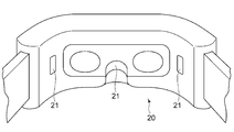
- the display device 20 is a device that displays a moving image presented to the viewer.
- the display device 20 is assumed to be a head-mounted display device that the viewer wears on his/her head.
- An electro-oculography sensor 21 is arranged on the surface of the display device 20 facing the viewer.
- the electro-oculography sensor 21 is a sensor that measures an electro-potential difference that occurs around the eyes of a person, which is called electro-oculography. By analyzing the detection result of this sensor, it is possible to identify the state and movement of the eyes such as the movement and blink of the line of sight of the viewer.
- the electro-oculography sensor 21 is arranged so as to come into contact with the skin around the viewer's eyes, for example, near the bridge of the viewer's nose or near the temples further outside the left and right eyes. The detection result of the electro-oculography sensor 21 is transmitted to the image processing device 10 in real time.
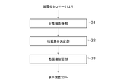
- the image processing apparatus 10 is functionally configured to include an eye information acquisition unit 31, a drawing condition determination unit 32, and a moving image drawing unit 33. These functions are realized by the control unit 11 executing a program stored in the storage unit 12. This program may be provided to the image processing apparatus 10 via a communication network such as the Internet, or may be provided by being stored in a computer-readable information storage medium such as an optical disk.
- the eye information acquisition unit 31 acquires information regarding the state of the eyes of a viewer who is browsing the moving image while the display device 20 is displaying the moving image.
- the eye information acquisition unit 31 acquires information regarding the blink timing of the viewer (hereinafter referred to as blink information) in real time and notifies the drawing condition determination unit 32 of the information.
- the eye information acquisition unit 31 can acquire blink information by analyzing the output of the electro-oculography sensor 21.
- FIG. 4 is an example of an electrooculogram (EOG) obtained from the detection result of the electrooculogram sensor 21.
- EOG electrooculogram
- the EOG value may be a value obtained by applying a predetermined filtering process such as a high pass filter to the detection result of the electro-oculography sensor 21.
- a waveform obtained by averaging the detection results obtained for the left and right eyes of the viewer is shown.
- the electro-oculogram in the vertical direction shows a periodic waveform due to the unconscious blinking performed by the viewer.
- the timing at which the rising of the peak starts indicates the timing at which the viewer starts closing his eyes due to blinking.
- the timing (To in the figure) at which the value starts to increase again after the fall of the peak indicates the timing at which the viewer starts to open his eyes.
- the eye information acquisition unit 31 monitors the absolute value of the EOG value, and/or the amount of change per unit time, and when the timing to start closing the eye and the timing to start opening the eye are specified, the eye information acquisition unit immediately informs that fact.
- the drawing condition determination unit 32 is notified as.
- the drawing condition determination unit 32 uses the blink information acquired by the eye information acquisition unit 31 to determine the drawing condition of the moving image displayed on the display device 20. In particular, the drawing condition determination unit 32 instructs the moving image drawing unit 33 to draw a frame image forming a moving image at predetermined intervals.
- the moving image drawing unit 33 which will be described later, draws a new frame image to be displayed next each time it receives a drawing instruction from the drawing condition determining unit 32.
- the drawing condition determination unit 32 suppresses the drawing of the moving image while the viewer unconsciously blinks and closes his eyes. Specifically, the drawing condition determination unit 32 suspends the periodic frame image drawing instruction when the eye information acquisition unit 31 notifies that the viewer has started to close his eyes by blinking. Further, when the eye information acquisition unit 31 notifies that the viewer has started to open his/her eyes, the drawing instruction of the frame image is restarted. According to such control, the update of the frame images forming the moving image is interrupted in the time zone in which it is assumed that the viewer's eyes are closed due to the blink.
- the moving image drawing unit 33 draws a moving image according to the drawing conditions determined by the drawing condition determining unit 32.
- the function of the moving image drawing unit 33 may be realized by a processor different from the processor that realizes the function of the drawing condition determining unit 32 such as a GPU (Graphics Processing Unit).
- the moving image drawing unit 33 draws a new frame image forming a moving image and outputs the new frame image to the display device 20 each time the drawing instruction is received from the drawing condition determining unit 32.
- the drawing condition determining unit 32 suspends the instruction to update the frame image, the frame image is not updated, and the frame image drawn in the latest past is continuously displayed again.
- FIG. 5 is a graph showing the drawing time of the frame image, and shows a state of the drawing control of the frame image in the time zone when the electro-oculogram of FIG. 4 was acquired.
- drawing of the frame image is interrupted by the control of the drawing condition determination unit 32 during the time period from the timing when the viewer starts closing his eyes to the timing when the viewer starts opening his eyes. Has been done.
- the average of the drawing time of each frame image including the processing waiting time should be shortened.
- the update frequency (frame rate) of the frame image can be lowered as a whole, as compared with the case where the frame image is always updated at a fixed time interval, and the process associated with the drawing process can be performed.
- the load can be reduced.
- the frame image is not updated at the timing when the viewer's eyes are closed, so it is unlikely that the viewer notices the decrease in the frame rate, and the quality of the moving image that the viewer feels is not affected. Few.
- the moving image drawing unit 33 may draw the frame image at a lower resolution than in other time zones instead of completely interrupting the updating of the frame image.
- the drawing condition determination unit 32 instructs the moving image drawing unit 33 to draw a frame image at a low resolution while it is assumed that the viewer has his eyes closed by blinking.
- the frame image drawn at the low resolution is enlarged and displayed on the display device 20 in the same size as other frame images. With such processing, the processing load associated with the drawing processing can be reduced while preventing the quality of the moving image viewed by the viewer from being affected.
- the frame image drawing process is interrupted at the timing when it is specified that the viewer has started to close his/her eyes, and the frame image drawing process is restarted at the timing when it is specified that the viewer has started to open his/her eyes.
- the present invention is not limited to this, and when the predetermined time elapses from the timing when the drawing process of the frame image is started to be interrupted, the drawing condition determination unit 32 draws the frame image regardless of the blink information at that time. The processing may be restarted. Regardless of the viewer's will, the reflexive blink time is assumed to be approximately constant.
- the frame image drawing process can be interrupted only while it is estimated that the frame image is closed.
- the drawing condition determining unit 32 not only controls the drawing process of the frame image according to the timing of the blink as described above, but also reduces the viewer's motion sickness by using the information about the state of the viewer's eyes. May be executed. This will be described below.
- the image processing apparatus 10 detects an abnormal pattern in which the state of the viewer's eyes changes abnormally, and performs display control for reducing the symptoms of motion sickness in accordance with the detection of such an abnormal pattern. By doing this, the symptoms of motion sickness can be resolved early.
- the eye information acquisition unit 31 monitors the vertical EOG waveform as described above while the viewer browses the moving image. Then, when a pattern (abnormal pattern) different from that caused by normal blinking appears in the waveform of the EOG, such as the occurrence frequency of blinking changing, the drawing condition determination unit 32 is notified of that fact. In order to make such a determination, the eye information acquisition unit 31 determines the blink pattern in the normal state at the timing when it is assumed that the sickness has not yet occurred, such as immediately after the viewer starts using the display device 20. You may acquire the value of the parameter (blink generation interval, peak size, etc.) shown. In this way, when a waveform in which the parameter values are different by a predetermined threshold value or more is observed compared to the normal pattern, it can be determined that an abnormal pattern has occurred.
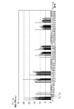
- FIG. 6 shows an example in which an abnormal pattern due to motion sickness occurs with respect to the vertical EOG.
- Tx the normal periodic blinking does not start, and a different abnormal pattern waveform appears.
- the drawing condition determination unit 32 does not perform the motion sickness reduction process immediately when an abnormal pattern is detected, but sets a predetermined condition such as when the waveform of the abnormal pattern is repeatedly detected within a predetermined period. If the condition is satisfied, the motion sickness reducing process may be performed. Further, detection of an abnormal blink pattern may be combined with other measurement results to determine whether or not the motion sickness reduction process is to be performed.
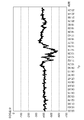
- the drawing condition determining unit 32 determines whether the motion sickness is abnormal based on the abnormal pattern of eye movement along the horizontal direction (left and right direction of the face) in addition to the abnormal pattern of blink specified by the EOG in the vertical direction. You may judge whether the symptom has appeared.
- the eye information acquisition unit 31 monitors the horizontal EOG as well as the vertical EOG, and when a predetermined abnormal pattern is detected in the detection result, the eye condition acquisition unit 31 indicates that fact. To notify.
- the EOG in the horizontal direction mainly indicates the movement of the line of sight of the left and right eyes of the viewer.
- the eye information acquisition unit 31 calculates the difference between the horizontal EOG values for the left and right eyes.
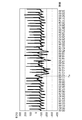
- FIG. 7 shows the temporal variation of the left-right difference of such horizontal EOG.
- the value of this difference indicates a shift in the movement of the left and right eyes, and when the shift occurs, it means that the left and right eyes make different movements.
- the difference value changes, it is estimated that the person is not intentionally changing the direction of the line of sight, but that abnormal microsaccades are occurring and that symptoms caused by motion sickness are appearing. To be done.
- the eye information acquisition unit 31 determines that an abnormal pattern of eye movement has occurred, for example, when the shift between the left and right eye movements indicated by the EOG difference value is equal to or greater than a predetermined threshold, and to that effect.
- the drawing condition determination unit 32 is notified. Ty in FIG. 7 indicates the timing at which such an abnormal pattern appears. For example, the drawing condition determination unit 32 determines that the initial symptom of sickness appears when both the abnormal pattern of blinking and the abnormal pattern of eye movement occur within a predetermined time.
- the drawing condition determination unit 32 determines that a sickness symptom appears based on the blinking abnormal pattern or the eye movement abnormal pattern notified by the eye information acquisition unit 31, the drawing condition determination unit 32 executes a sickness reduction process. Specifically, the moving image drawing unit 33 is instructed to execute a moving image drawing process that makes the motion sickness less likely to occur.
- motion sickness reduction processing include increasing the frame rate (increasing the frequency of drawing frame images), blurring the entire frame image by a blur effect, and reducing the overall contrast and saturation.
- processing include changing the color of the frame image.
- viewpoint position viewpoint camera
- the moving speed of the viewpoint position is controlled. May be. Specifically, by reducing the moving speed of the viewpoint camera, it is possible to make the symptoms of motion sickness less likely to occur.
- the eye information acquisition unit 31 continues to monitor the abnormal pattern of blinking and eye movement while the process of reducing motion sickness is being executed.
- the drawing condition determination unit 32 may determine that the sickness symptom is alleviated by the motion sickness reduction process and terminate the motion sickness reduction process if the abnormal pattern does not occur for a predetermined time.
- FIG. 8 shows an example of the flow of processing executed by the drawing condition determination unit 32 described above.
- This drawing shows the flow of processing executed by the drawing condition determining unit 32 each time a predetermined frame update time elapses.
- the drawing condition determination unit 32 branches the process depending on whether or not the drawing process is currently suspended (S1). If the drawing process is not in a suspended state, it is determined whether the start of blinking (timing to start closing eyes) is notified from the eye information acquisition unit 31 (S2). When the start of blinking is notified, the state is changed to a state where the drawing process of the frame image is suspended (S3), and the process of the frame is ended. On the other hand, if the start of blinking has not been notified, the process proceeds to S5, which will be described later, to instruct drawing of a frame image.
- the drawing condition determination unit 32 When executing the frame image drawing process, the drawing condition determination unit 32 subsequently branches the process depending on whether or not the motion sickness reduction process is currently being executed (S5). When the motion sickness reduction process is not being executed, it is determined whether or not an abnormal pattern of blinking or eye movement indicating an initial symptom of motion sickness is detected (S6). When it is determined that an abnormal pattern due to motion sickness has occurred, a transition is made to a state of executing motion sickness reduction processing (S7), and a moving image is drawn so as to draw a frame image under conditions that reduce motion sickness. Instruct the unit 33 (S8). On the other hand, if the abnormal pattern due to motion sickness is not detected, the frame image drawing unit 33 is instructed to draw the frame image under the normal condition (S9).
- the processing load associated with drawing can be reduced by suppressing the drawing of the frame image using the information about the blink of the viewer. Further, by utilizing the information regarding the state of the eyes of the viewer, it is possible to detect the symptoms of sickness at an early stage and deal with them.
- the embodiment of the present invention is not limited to the above description.
- the display device 20 is a head-mounted display device in the above description
- the display device 20 is not limited to this and may be a stationary type.
- the electro-oculography sensor 21 may be attached to the viewer as a device independent of the display device 20.
- the information regarding the movement of the viewer's eyes may be acquired not only by the electro-oculography sensor but also by other sensors.
- the image processing system 1 may specify the timing of the viewer's blink or the movement of the line of sight by analyzing the image captured by the camera device directed to the position of the viewer's eyes.
- 1 image processing system 10 image processing device, 11 control unit, 12 storage unit, 13 interface unit, 20 display device, 21 electrooculogram sensor, 31 eye information acquisition unit, 32 drawing condition determination unit, 33 moving image drawing unit.
Landscapes
- Engineering & Computer Science (AREA)
- Theoretical Computer Science (AREA)
- Physics & Mathematics (AREA)
- General Physics & Mathematics (AREA)
- Human Computer Interaction (AREA)
- Multimedia (AREA)
- General Engineering & Computer Science (AREA)
- General Health & Medical Sciences (AREA)
- Ophthalmology & Optometry (AREA)
- Health & Medical Sciences (AREA)
- Computer Vision & Pattern Recognition (AREA)
- Computer Hardware Design (AREA)
- Controls And Circuits For Display Device (AREA)
- Transforming Electric Information Into Light Information (AREA)
- User Interface Of Digital Computer (AREA)
Priority Applications (2)
| Application Number | Priority Date | Filing Date | Title |
|---|---|---|---|
| JP2020559145A JP7414731B2 (ja) | 2018-12-04 | 2019-11-29 | 画像処理装置、画像処理システム、画像処理方法、及びプログラム |
| US17/294,851 US20220019790A1 (en) | 2018-12-04 | 2019-11-29 | Image processing apparatus, image processing system, image processing method, and program |
Applications Claiming Priority (2)
| Application Number | Priority Date | Filing Date | Title |
|---|---|---|---|
| JP2018-227190 | 2018-12-04 | ||
| JP2018227190 | 2018-12-04 |
Publications (1)
| Publication Number | Publication Date |
|---|---|
| WO2020116348A1 true WO2020116348A1 (ja) | 2020-06-11 |
Family
ID=70975124
Family Applications (1)
| Application Number | Title | Priority Date | Filing Date |
|---|---|---|---|
| PCT/JP2019/046822 Ceased WO2020116348A1 (ja) | 2018-12-04 | 2019-11-29 | 画像処理装置、画像処理システム、画像処理方法、及びプログラム |
Country Status (3)
| Country | Link |
|---|---|
| US (1) | US20220019790A1 (enExample) |
| JP (1) | JP7414731B2 (enExample) |
| WO (1) | WO2020116348A1 (enExample) |
Cited By (2)
| Publication number | Priority date | Publication date | Assignee | Title |
|---|---|---|---|---|
| JPWO2022255147A1 (enExample) * | 2021-06-03 | 2022-12-08 | ||
| JP2025503553A (ja) * | 2021-12-30 | 2025-02-04 | ジョンテ キム | デジタル漫画の提供方法、装置、及びシステム |
Families Citing this family (1)
| Publication number | Priority date | Publication date | Assignee | Title |
|---|---|---|---|---|
| JP2024077145A (ja) * | 2022-11-28 | 2024-06-07 | キヤノン株式会社 | 処理装置、処理方法 |
Citations (5)
| Publication number | Priority date | Publication date | Assignee | Title |
|---|---|---|---|---|
| US20120134543A1 (en) * | 2010-11-30 | 2012-05-31 | Fedorovskaya Elena A | Method of identifying motion sickness |
| JP2013110662A (ja) * | 2011-11-24 | 2013-06-06 | Seiko Epson Corp | 装置、頭部装着型表示装置、装置の制御方法および頭部装着型表示装置の制御方法 |
| JP2017042269A (ja) * | 2015-08-25 | 2017-03-02 | トヨタ自動車株式会社 | 瞬目検知装置 |
| US20170178408A1 (en) * | 2015-12-22 | 2017-06-22 | Google Inc. | Adjusting video rendering rate of virtual reality content and processing of a stereoscopic image |
| JP2018514005A (ja) * | 2015-02-05 | 2018-05-31 | 株式会社ソニー・インタラクティブエンタテインメント | 乗り物酔いの監視及び、酔いを抑えるための追加音の付与 |
Family Cites Families (2)
| Publication number | Priority date | Publication date | Assignee | Title |
|---|---|---|---|---|
| US9081416B2 (en) * | 2011-03-24 | 2015-07-14 | Seiko Epson Corporation | Device, head mounted display, control method of device and control method of head mounted display |
| JP2019041841A (ja) * | 2017-08-30 | 2019-03-22 | 株式会社トプコン | 眼科装置、及びその制御方法 |
-
2019
- 2019-11-29 US US17/294,851 patent/US20220019790A1/en not_active Abandoned
- 2019-11-29 WO PCT/JP2019/046822 patent/WO2020116348A1/ja not_active Ceased
- 2019-11-29 JP JP2020559145A patent/JP7414731B2/ja active Active
Patent Citations (5)
| Publication number | Priority date | Publication date | Assignee | Title |
|---|---|---|---|---|
| US20120134543A1 (en) * | 2010-11-30 | 2012-05-31 | Fedorovskaya Elena A | Method of identifying motion sickness |
| JP2013110662A (ja) * | 2011-11-24 | 2013-06-06 | Seiko Epson Corp | 装置、頭部装着型表示装置、装置の制御方法および頭部装着型表示装置の制御方法 |
| JP2018514005A (ja) * | 2015-02-05 | 2018-05-31 | 株式会社ソニー・インタラクティブエンタテインメント | 乗り物酔いの監視及び、酔いを抑えるための追加音の付与 |
| JP2017042269A (ja) * | 2015-08-25 | 2017-03-02 | トヨタ自動車株式会社 | 瞬目検知装置 |
| US20170178408A1 (en) * | 2015-12-22 | 2017-06-22 | Google Inc. | Adjusting video rendering rate of virtual reality content and processing of a stereoscopic image |
Cited By (3)
| Publication number | Priority date | Publication date | Assignee | Title |
|---|---|---|---|---|
| JPWO2022255147A1 (enExample) * | 2021-06-03 | 2022-12-08 | ||
| WO2022255147A1 (ja) * | 2021-06-03 | 2022-12-08 | ソニーセミコンダクタソリューションズ株式会社 | 表示装置、表示システム、および表示駆動方法 |
| JP2025503553A (ja) * | 2021-12-30 | 2025-02-04 | ジョンテ キム | デジタル漫画の提供方法、装置、及びシステム |
Also Published As
| Publication number | Publication date |
|---|---|
| JPWO2020116348A1 (ja) | 2021-10-28 |
| JP7414731B2 (ja) | 2024-01-16 |
| US20220019790A1 (en) | 2022-01-20 |
Similar Documents
| Publication | Publication Date | Title |
|---|---|---|
| EP3820353B1 (en) | Electronic devices with display operation based on eye activity | |
| JP7414731B2 (ja) | 画像処理装置、画像処理システム、画像処理方法、及びプログラム | |
| US11583178B2 (en) | Systems and methods for evaluating contrast sensitivity and other visual metrics | |
| CN112150601B (zh) | 中央凹渲染的方法、计算系统和非暂时性机器可读介质 | |
| US11196975B2 (en) | Image generating device, image display system, and image generating method | |
| JP7001832B2 (ja) | 視標追跡システムの画像調整 | |
| US9256069B2 (en) | Image processing apparatus image processing method and program using electrodes contacting a face to detect eye gaze direction | |
| US20140200079A1 (en) | Systems and methods for differentiating between dominant and weak eyes in 3d display technology | |
| US20140081117A1 (en) | Eye fatigue determination apparatus and eye fatigue determination method | |
| WO2020016970A1 (ja) | 情報処理装置、情報処理方法、及びプログラム | |
| KR20160006337A (ko) | 사용자의 눈 깜빡임을 유도하는 유도 영상 표시 방법, 장치, 및 컴퓨터 판독 가능한 기록매체 | |
| WO2023011103A1 (zh) | 参数控制方法、装置、头戴式显示设备以及存储介质 | |
| TWI811613B (zh) | 頭戴式顯示裝置及其控制方法與校正方法 | |
| US11125997B2 (en) | Information processing apparatus, information processing method, and program | |
| US10503252B2 (en) | System and method for eye-reactive display | |
| JPWO2020116348A5 (enExample) | ||
| EP4418076A1 (en) | Graphics rendering apparatus and method | |
| WO2017022302A1 (ja) | 情報処理装置、情報処理方法およびプログラム | |
| US20230068868A1 (en) | Display device, control method thereof, and recording medium | |
| KR102535639B1 (ko) | 증강현실기기의 시각적 복잡도 완화방법, 및 동 방법을 컴퓨터에서 실행하기 위한 컴퓨터 프로그램이 기록된, 컴퓨터 판독 가능한 기록 매체 | |
| JP7467094B2 (ja) | 情報処理装置、情報処理方法、及びプログラム | |
| WO2020016969A1 (ja) | 情報処理装置、情報処理方法、及びプログラム | |
| US12248624B1 (en) | Display apparatus incorporating artificial saccade elongation | |
| JPH08266477A (ja) | 表示装置 | |
| JP2025088449A (ja) | 仮想現実視聴システム、仮想現実視聴方法、仮想現実視聴プログラム及び仮想現実視聴装置 |
Legal Events
| Date | Code | Title | Description |
|---|---|---|---|
| 121 | Ep: the epo has been informed by wipo that ep was designated in this application |
Ref document number: 19893133 Country of ref document: EP Kind code of ref document: A1 |
|
| ENP | Entry into the national phase |
Ref document number: 2020559145 Country of ref document: JP Kind code of ref document: A |
|
| NENP | Non-entry into the national phase |
Ref country code: DE |
|
| 122 | Ep: pct application non-entry in european phase |
Ref document number: 19893133 Country of ref document: EP Kind code of ref document: A1 |