WO2020116342A1 - 検査方法および検査装置、ならびに築炉方法 - Google Patents
検査方法および検査装置、ならびに築炉方法 Download PDFInfo
- Publication number
- WO2020116342A1 WO2020116342A1 PCT/JP2019/046787 JP2019046787W WO2020116342A1 WO 2020116342 A1 WO2020116342 A1 WO 2020116342A1 JP 2019046787 W JP2019046787 W JP 2019046787W WO 2020116342 A1 WO2020116342 A1 WO 2020116342A1
- Authority
- WO
- WIPO (PCT)
- Prior art keywords
- refractory
- mortar layer
- electromagnetic wave
- phase
- voids
- Prior art date
- Legal status (The legal status is an assumption and is not a legal conclusion. Google has not performed a legal analysis and makes no representation as to the accuracy of the status listed.)
- Ceased
Links
Images




Classifications
-
- C—CHEMISTRY; METALLURGY
- C10—PETROLEUM, GAS OR COKE INDUSTRIES; TECHNICAL GASES CONTAINING CARBON MONOXIDE; FUELS; LUBRICANTS; PEAT
- C10B—DESTRUCTIVE DISTILLATION OF CARBONACEOUS MATERIALS FOR PRODUCTION OF GAS, COKE, TAR, OR SIMILAR MATERIALS
- C10B29/00—Other details of coke ovens
- C10B29/02—Brickwork, e.g. casings, linings, walls
-
- F—MECHANICAL ENGINEERING; LIGHTING; HEATING; WEAPONS; BLASTING
- F27—FURNACES; KILNS; OVENS; RETORTS
- F27D—DETAILS OR ACCESSORIES OF FURNACES, KILNS, OVENS OR RETORTS, IN SO FAR AS THEY ARE OF KINDS OCCURRING IN MORE THAN ONE KIND OF FURNACE
- F27D1/00—Casings; Linings; Walls; Roofs
-
- G—PHYSICS
- G01—MEASURING; TESTING
- G01N—INVESTIGATING OR ANALYSING MATERIALS BY DETERMINING THEIR CHEMICAL OR PHYSICAL PROPERTIES
- G01N22/00—Investigating or analysing materials by the use of microwaves or radio waves, i.e. electromagnetic waves with a wavelength of one millimetre or more
- G01N22/02—Investigating the presence of flaws
Definitions
- the present invention relates to an inspection method and an inspection apparatus for stacking standard refractory materials or irregular refractory materials, and a furnace construction method.
- furnaces used for steelmaking such as coke ovens, blast furnaces, and converters, but since they are used at high temperatures, refractory materials are used for the surfaces that come into contact with the materials.
- refractory materials are used for the surfaces that come into contact with the materials.
- bricks (standard refractory materials) and castable materials refractory materials made by pouring wall materials into molds and hardening
- Such work is called a furnace.
- a furnace is built by stacking refractories by hand-building by a builder and an automatic system.
- the furnace construction by the automatic system is described in Patent Document 1, for example.
- Mortar is applied during stacking of individual refractories during furnace construction work in order to fix the gaps between refractories (hereinafter referred to as joints) and to secure the gas/liquid sealability.
- joints refractories
- the application of mortar is performed at the position where the refractory is loaded so as to have a predetermined joint thickness using a trowel, but with an automatic system such as Patent Document 1, the mortar is automatically applied. Supplying means are used. After applying the mortar, the refractory is placed on the mortar so that the air is not blocked. If the refractory is large and heavy, a hoist may be used.
- voids air regions
- the refractory materials may remain inside the mortar layer, and if the voids exceed a certain ratio, the refractory materials will not be fixed or sealed sufficiently, and operation will not be possible during actual operation. It may become stable or even cause a disaster or accident. Therefore, in the inspection work, it is important to inspect the voids in the mortar layer.
- the refractory must be peeled off and inspected, which is troublesome. Also, if the number of refractory materials piled up is large, the inspection will take time, and overall inspection is difficult in terms of time.Therefore, it is necessary to perform a sampling inspection, but the sampling inspection cannot reliably identify the voids in the mortar layer. ..
- an object of the present invention is to provide an inspection method, an inspection apparatus, and a furnace building method capable of efficiently and surely grasping the voids of a mortar layer used when building a furnace by stacking refractory materials. To do.
- the present invention provides the following (1) to (12).
- An inspection method for stacking refractory materials through a mortar layer to build a furnace An inspection method for detecting an air gap in the mortar layer by scanning an inspection device having a function of detecting the presence of an air gap in the mortar layer.
- a step of stacking refractory materials through a mortar layer A step of detecting voids in the mortar layer by the inspection method according to any one of (1) to (9); A method of constructing a furnace.
- An inspection device for detecting voids in a mortar layer when a refractory material is piled up via a mortar layer to construct a furnace.
- An antenna that is attached to the dolly and radiates electromagnetic waves to the upper surface of the refractory
- An electromagnetic wave analyzer that is housed in the carriage, outputs electromagnetic waves, and measures reflected electromagnetic waves when the electromagnetic waves are emitted from the antenna to the upper surface of the refractory
- a data processing unit that processes data measured by the electromagnetic wave analysis device, and detects a void in the mortar layer
- Have An inspection device that detects voids in the mortar layer while scanning the carriage.
- the electromagnetic wave analysis device outputs a broadband electromagnetic wave generated from an electrical short-time pulse, measures a reflected waveform for each frequency, converts multifrequency response data into time domain data, and converts the reflected electromagnetic wave.
- the data processing unit irradiates the refractory with electromagnetic waves, determines the relative position of the refractory and the antenna using the reflection intensity from the upper surface of the refractory, and determines the reflected wave from the relative position.
- the carriage has wheels for scanning the refractory material, and an encoder provided on the wheels,
- the inspection apparatus according to any one of (10) to (12) above, wherein the pulse of the encoder is input to the electromagnetic wave analysis apparatus as a measurement trigger.
- the inspection device having the function of detecting the presence of voids in the mortar layer is scanned, and the voids in the mortar layer are detected. It can be grasped efficiently and reliably without peeling. Therefore, the quality of the refractory stacking can be immediately determined.
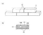
- FIG. (A) is a figure which shows the state of the bricks 11 piled up by interposing the mortar layer 13
- (b) is a figure which shows the space
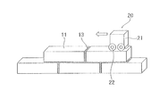
- It is a perspective view explaining the state which is inspecting using the inspection device which has a function which detects the existence of a void in the mortar layer 13.
- It is a schematic diagram showing a gap detection function part using an electromagnetic wave of an inspection device for performing an inspection method concerning one embodiment of the present invention.
- FIG. 6 is a flowchart showing an inspection flow using the inspection device 20 having the void detection function unit 30 having the void detection function unit 30 of FIG. 4. It is a figure which shows the processing flow in an inspection flow. It is a figure which shows the example of a waveform of reflection intensity among the data of a time domain. It is the figure which made the time domain data from the multi-frequency response data by the inverse Fourier transform, and took a certain time plane, and is a figure showing the example which fixes and measures the phase to observe. It is a figure which shows the space
- FIG. 1 is a diagram showing a brick stacking state at the time of coke oven building using bricks as a standard refractory, as an example showing a situation at the time of furnace building, (a) is a sectional view in the furnace length direction, (b) ) Is a sectional view in the furnace width direction.
- bricks 11 are arranged in the furnace length direction and stacked in the height direction to form one gate 12, and a plurality of such gates 12 are arranged at predetermined intervals in the furnace width direction. It has an ordered structure.
- the coke oven is designed so that the upper and lower bricks 11, which are standard refractories, have horizontal connection surfaces and are aligned at the same height throughout, and are counted as the first and second stages from the bottom.
- mortar is applied to a position where bricks 11 which are standard refractories are stacked, and the bricks 11 are stacked thereon.
- the position of the stacked bricks is adjusted by using a leveler or the like, and then the bricks are moved in the lateral direction, and the next brick 11 is stacked.
- the bricks 11 for one step are piled up by repeating the above procedure.
- the mortar applied when the bricks 11 are stacked is present as a mortar layer 13 between the adjacent bricks 11.
- the mortar layer 13 is used to fix the joint and to secure the gas sealing property.
- the mortar layer 13 may have voids 14 as shown in FIG. 2(b). If the voids 14 are more than a certain ratio, fixation between the bricks 11 and sealing properties will be insufficient, which may cause unstable operation during actual operation, or may cause a disaster or accident in some cases. ..
- the voids in the mortar layer 13 are inspected, conventionally, after the bricks 11 have been stacked for one step, the bricks are turned over once and the filling state of the mortar is visually inspected. As shown in FIG. 2B, when the voids 14 are present in the mortar layer 13 of the bent brick 11, the size of the voids is measured by applying a ruler, and the area of the voids 14 is 10 of the total area of the mortar layer 13. If it is over %, it will be reloaded.
- the inspection is performed using the inspection device having the function of detecting the presence of the void 14 in the mortar layer 13 formed between the adjacent bricks 11.
- the inspection device having the function of detecting the presence of the void 14 in the mortar layer 13 formed between the adjacent bricks 11.
- FIG. 3 by scanning the piled bricks 11 with the inspection device 20, it is possible to easily detect the presence of voids and the percentage of voids in the mortar layer 13 on the entire surface without turning the bricks. You can
- the inspection device 20 has a carriage 21 having a void detection function unit inside and wheels 22, and the wheels 22 travel on the bricks 11. However, the worker may move it.
- the void detection function unit of the inspection device 20 is not particularly limited as long as it has a function of detecting the presence of voids in the mortar layer 13, and examples thereof include those using electromagnetic waves.
- FIG. 4 is a schematic diagram showing a void detection function unit using electromagnetic waves.
- the gap detection function unit 30 has a power supply 23, an antenna 24, a network analyzer 25, an encoder 26, a monitor 27, and a data processing unit 28.
- the antenna 24 is for irradiating electromagnetic waves, and is provided below the carriage 21 so that the opening surface of the brick 11 faces the upper surface of the brick 11.
- a gap of about 1 mm to 5 mm is provided between the upper surface of the brick 11 and the opening surface of the antenna 24 so that the brick 11 and the opening surface of the antenna 24 do not come into contact with each other. Therefore, it is desirable that the inspection device 20 has a mechanism capable of adjusting the gap.
- the antenna 24 is not particularly limited in shape and form, and various types such as a horn antenna, a patch antenna and a plane antenna can be used.
- the network analyzer 25 is housed in the carriage 21 and outputs an electromagnetic wave, and functions as an electromagnetic wave analyzer that analyzes a reflected electromagnetic wave. More specifically, the network analyzer 25 outputs a wide-area electromagnetic wave generated from an electrical short-time pulse.
- the device is capable of multi-frequency analysis. However, not limited to this, any distance measuring method using electromagnetic waves (for example, FMCW modulation method) can be used.
- the encoder 26 is attached to the wheel 22.
- the pulse of the encoder 26 can be used as a measurement trigger.
- the monitor 27 is provided on the upper surface of the truck 21 and displays the analysis result of the network analyzer 25 and the like.
- the data processing unit 28 processes the data measured by the network analyzer 25.
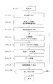
- FIG. 5 is a flowchart showing the inspection flow.
- step 1 turn on the power (step 1).
- step 2 the settings of the network analyzer 25 are read (step 2), and the reference bricks are measured and the observation time range is set (step 3).
- step 3 The measurement preparation is completed as described above, and the measurement start button is operated (step 4).
- the encoder 26 outputs an encoder pulse that serves as a measurement start trigger (step 5). Then, the electromagnetic wave output from the network analyzer 25 is emitted from the antenna 24, the reflected wave is measured by the network analyzer 25 (step 6), and the measurement data is stored in the memory of the network analyzer 25 or the like (step 7). Then, the data processing unit 28 performs data processing of the measurement data (step 8), and the processing result is displayed on the monitor 27 and stored in the memory (step 9). After steps 5 to 9 are repeated a predetermined number of times as necessary, the end button is turned on (step 10) and the measurement ends.
- the network analyzer 25 has the frequency band and the number of measurement data points set in advance.
- the network analyzer 25 has a time domain function (TDR function) for displaying data in the time domain instead of the frequency domain, and in the first embodiment, this TDR function is used during the measurement in step 6.
- the network analyzer 25 outputs broadband electromagnetic waves, and its frequency band is, for example, 6 GHz to 15 GHz and the number of measurement data points is 1000 points.
- the network analyzer 25 outputs an electromagnetic wave at a pitch of 6 GHz to 9 MHz and measures a reflected waveform for each frequency. It is possible to convert multi-frequency response data into time domain data. For example, inverse Fourier transform is performed.
- the data in the time domain is a vector value composed of real number data and imaginary number data. Therefore, not only the intensity but also the phase can be obtained.
- the frequency to be used in general, high frequency has good distance resolution, but attenuation in refractory is large, and low frequency has small attenuation, but distance resolution is poor. Since concrete has a high density and does not sufficiently penetrate at high frequencies (several tens of GHz), low frequencies (several GHz) are often used. On the other hand, refractory bricks (particularly silica stone bricks used in furnace construction, etc.) have relatively low density and can use high frequencies. However, if the frequency is too high, it cannot sufficiently penetrate the thickness of the brick. Therefore, the desirable value of the frequency used is in the range of 6 GHz to 15 GHz. When sweeping frequencies, it takes time if the frequency band is wide. The measurement time can be shortened by cutting the low frequency side where the sensitivity is low. Therefore, the frequency band is set to 4 GHz to 18 GHz so as to include the desired value.
- this required time is set in advance, and the reflection intensity and phase at that time are stored in a memory such as the network analyzer 25. Recorded (saved).
- the data processing unit 28 determines the void based on the obtained reflection intensity and phase and the preset intensity threshold and phase range.
- the data processing flow is shown in FIG. First, the surface reflection peak value and the peak position are searched (step 11). Next, using the reflection intensity (surface reflection peak value) from the brick top surface, the relative position between the brick and the antenna is determined, and the boundary between the brick and the mortar layer or void is determined from the determined relative position and the peak position of the reflection intensity. The reflection position of the surface and the phase correction amount are set (step 12). Next, the reflection intensity of the boundary surface is corrected by the surface reflection intensity, and the reflection phase is corrected by using the phase correction amount (step 13). Next, void determination is performed (step 14), and the truck position, boundary surface strength, phase, and void determination are recorded (step 15).
- FIG. 7 is a diagram showing an example of a waveform of the reflection intensity in the time domain data. Phase data is acquired separately.
- reflection returns from the boundary surface between the brick and the mortar layer or the void after a certain period of time from the electromagnetic wave irradiation. This required time is set in advance, and the reflection intensity and phase at that time are saved.
- the threshold value of the reflected wave intensity indicating the void or mortar layer is set to the threshold value 1.
- the phase of the void (air layer) is set to 30 to 90°, and the phase of the mortar layer is set to -10 to -50°.
- the separately calculated phase is 60°, so that it can be determined as a void
- the separately calculated phase is ⁇ 40°, and thus the mortar. It can be determined as a layer.
- threshold 2 is set as the threshold of the reflection intensity at the boundary position 14E between the mortar layer 13 and the void 14, and if the reflection intensity is smaller than the threshold 2 as shown in FIG. It can be determined as a boundary position 14E between the space 13 and the void 14.
- the data processing unit 28 may determine that the boundary position 14E is a possible candidate.
- the reflection intensity when the reflection intensity is smaller than the threshold value 1 and the phase is close to the void phase, it can be determined as a small void close to the boundary position 14E between the mortar layer 13 and the void 14.
- the phase changes because the electromagnetic characteristics of the medium in which the electromagnetic wave propagates are different.
- the dielectric constants of air, brick, and mortar are different, the phase changes when each boundary is present.
- the magnitude relation and values of these dielectric constants are as follows. Air (1) ⁇ Brick (3-4) ⁇ Mortar (10-80) Since the permittivity of mortar varies greatly depending on the amount of water, it has a wide range of 10 to 80, but is a value different from the permittivity of air and brick.
- the phase changes depending on the relative position between the antenna surface and the brick surface (hereinafter, these distances are referred to as "lift-off"), the thickness of the propagating bricks, etc., it is necessary to calibrate and correct them.
- the brick thickness may be calibrated with the reference thickness before the measurement.
- the relative position (distance) of the electromagnetic waves from the uppermost surface of the brick is calculated from the reflection intensity (reflection peak position), and the phase is corrected from the relative position (distance). For example, if a frequency near 10 GHz is used, the wavelength is about 30 mm, and therefore changes by 12° per 1 mm.
- the phase is corrected by lift-off during measurement.
- the reflection intensity and phase of the electromagnetic wave it is possible to grasp the presence and the size of the void in the mortar layer. Therefore, the voids in the bricks can be grasped efficiently and reliably on the entire surface without peeling the bricks.
- FIG. 8 is a diagram in which response data of multiple frequencies is transformed into time domain data by inverse Fourier transform and a certain time plane is taken, and is a diagram showing an example in which the observed phase is fixed and measured.
- the phase is 30° (left side in FIG. 8)
- the signal from the void (air layer) becomes 90°.
- signal processing of +60° is added to the measurement data (right side of FIG. 8).
- the output data can be observed at the phase where the reflection component from the air layer has the maximum value.
- the phase is converted to 10° by signal processing as shown on the right side of FIG. Is a small absolute value and can be distinguished from the air layer.
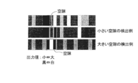
- FIG. 9 is a two-dimensional void map obtained by scanning three times.
- the magnitude of the output value is shown in multiple stages from black (small output value) to white (large output value).
- the reflection intensity from the boundary position 14E is smaller than the reflection intensity from the mortar layer 13 and the void 14. Therefore, a region having a large output value sandwiched between small output values is detected as a void. As a result, a small void is detected in the second stage and a large void is detected in the third stage.
- the product quality of bricks is evaluated by the ratio of void areas in the scanned area. For example, as described above, if the area of the void is 10% or more of the total area, it is reloaded. In the example of FIG. 9, out of 57 squares in total, 4 squares are voids, and the percentage of voids is less than 10%, so that re-loading is not necessary.
- the inspection device having the function of detecting the presence of voids in the mortar layer is scanned to detect the voids in the mortar layer. It is possible to grasp efficiently and surely without peeling off objects. Therefore, the quality of the refractory stacking can be immediately determined.
- the detection of voids can be performed with high precision by using electromagnetic waves.
- the accuracy of discrimination between the mortar layer and the voids is improved, and higher precision is achieved.
- the void can be detected with.
- the inspection device having the function of detecting the presence of the voids in the mortar layer 13 the inspection device having the void detection function part using the electromagnetic wave is exemplified, but the invention is not limited to this. It is also possible to detect the gap using other means such as a sound wave, a water content measuring device, and a current-carrying device.
- the example which used the brick which is a standard refractory as a refractory was shown, it may be another standard refractory or an irregular refractory.
- the construction of the coke oven is shown, but the present invention can be applied to the construction of other furnaces such as a blast furnace and a converter.
- FIG. 10 is a graph showing a second embodiment according to the inspection method, the inspection apparatus, and the furnace construction method of the present invention, and the second embodiment will be described with reference to FIG. FIG. 10 shows a change in phase with time. Further, in the following description of the second embodiment, parts having the same configurations as those in FIGS. 1 to 9 are designated by the same reference numerals and the description thereof will be omitted.
- the inspection method of FIG. 10 is different from the inspection methods of FIGS. 1 to 9 in that the void is detected based on the difference in the propagation velocity (phase change) of the electromagnetic wave in the mortar layer and in the void.
- the phase velocity and the propagation velocity which indicate the velocity of the phase change of electromagnetic waves, are different when propagating in the mortar layer and in the void.
- the solid line shows the phase at the measurement position where there is no void and the mortar layer is filled
- the dotted line shows the waveform and phase of the reflection intensity at the position where there is a void in the mortar layer.
- the network analyzer 25 outputs a wide-band electromagnetic wave at a pitch of 6 GHz to 9 MHz, for example, and measures a reflected waveform for each frequency.
- the waveforms of the reflection intensity and the phase data of both are almost the same.
- the waveforms of the reflection intensity and the phase data are different when there is a void and when there is no void and the mortar layer is filled. This is because the mortar layer and the voids have different dielectric constants. That is, as the dielectric constant increases, the phase change speed increases, the wavelength decreases, and the propagation speed decreases.
- the data processing unit 28 determines the presence or absence of a void based on the change in the phase velocity. Specifically, the data processing unit 28 calculates the propagation velocity from the phase data based on the inclination per unit time. At this time, the data processing unit 28 may correct the phase data based on the relative position between the brick and the antenna 24, as described above. Then, the data processing unit 28 detects the position of the boundary surface between the brick and the mortar layer or the boundary surface between the brick and the void by detecting the change in the propagation velocity.
- the data processing unit 28 determines whether the boundary surface is a mortar layer or a void based on the propagation velocity. That is, as described above, the dielectric constant of the mortar layer is larger than the dielectric constant of the void. Therefore, for example, the data processing unit 28 may determine that it is a void if the propagation speed changes so as to increase, and may determine that it is a mortar layer if it changes so that the propagation speed decreases. Further, in combination with the first embodiment, for example, the data processing unit 28 may detect the void by calculating the propagation intensity based on the phase data of the portion where the reflection intensity is larger than the threshold value.
- the propagation velocity of the electromagnetic wave by using the propagation velocity of the electromagnetic wave, the presence or absence of the void in the mortar layer and its size can be grasped. Therefore, the voids in the bricks can be grasped efficiently and reliably on the entire surface without peeling the bricks.
- the void can be detected by the same method.
- the electromagnetic wave propagates in the order of the brick, the mortar layer, and the void, and the phase velocity changes at the boundary surface of each region.
- Voids in the mortar layer can be detected by detecting the time (position) at which the phase velocity changes and the phase velocity.
Landscapes
- Chemical & Material Sciences (AREA)
- Engineering & Computer Science (AREA)
- Physics & Mathematics (AREA)
- Biochemistry (AREA)
- General Physics & Mathematics (AREA)
- Oil, Petroleum & Natural Gas (AREA)
- Electromagnetism (AREA)
- Health & Medical Sciences (AREA)
- Life Sciences & Earth Sciences (AREA)
- Analytical Chemistry (AREA)
- Materials Engineering (AREA)
- General Health & Medical Sciences (AREA)
- Organic Chemistry (AREA)
- Immunology (AREA)
- Pathology (AREA)
- Mechanical Engineering (AREA)
- General Engineering & Computer Science (AREA)
- Furnace Housings, Linings, Walls, And Ceilings (AREA)
- Waste-Gas Treatment And Other Accessory Devices For Furnaces (AREA)
- Length-Measuring Devices Using Wave Or Particle Radiation (AREA)
Abstract
耐火物を、モルタル層を介して積み上げて築炉する際の検査方法であって、モルタル層内に空隙が存在することを検知する機能を有する検査装置を走査させて、モルタル層内の空隙を検知する。
Description
本発明は、定型耐火物または不定形耐火物を積み上げる際の検査方法および検査装置、ならびに築炉方法に関する。
製鉄に用いられる炉には、コークス炉、高炉、転炉など様々なものがあるが、それぞれ高温下で使用されるため、材料と接する面は耐火物が使用される。このような炉の建築もしくは補修時には、一般的にレンガ(定型耐火物)やキャスタブル材(型に壁材を流し込み固めてつくる耐火物)を積み上げていく作業が生じる。このような作業を築炉と呼ぶ。
築炉は、築炉工による手積みや自動システムにより、耐火物を積み上げることにより行われる。自動システムによる築炉については、例えば特許文献1に記載されている。
築炉作業における個々の耐火物の積み上げの際は、耐火物どうしの隙間(以降目地と呼ぶ)を固定するため、およびガス・液体のシール性を確保するためにモルタルが塗布される。モルタルの塗布は、手積みの場合には、耐火物を積む位置に、コテを用いて所定の目地厚になるように行われるが、特許文献1のような自動システムでは、自動的にモルタルを供給する手段が用いられる。モルタルを塗布した後は、空気がかまないようにモルタル上へ耐火物を積む。耐火物が大きく重い場合には、ホイストなどを利用する場合もある。
積まれた定型耐火物の位置を、水平器等を利用して調整した後、次の定型耐火物を積む位置へ横方向に移動する。以上の手順を繰り返し行うことで1段分の定型耐火物を積んでいく。
上記いずれの施工手法をとった場合でも、高い精度を維持しつつ耐火物を積み上げることが要求されるため、1段分の耐火物積み上げ作業が終了すると、検査作業を行い、問題が発見された場合はその部分を積みなおした後、次の段の積み上げ作業に入る。
また、モルタル層の内部には空隙(空気の領域)が残る場合があり、空隙がある割合以上となると、耐火物どうしの固定やシール性などが不十分となり、実操業の際に操業が不安定になったり、場合によっては災害・事故の原因になる可能性がある。このため、検査作業においては、モルタル層の空隙を検査することも重要である。
しかしながら、モルタル層の空隙については、耐火物を剥がして検査せざるを得ず、手間がかかる。また、積み上げる耐火物の個数が多くなると検査に時間がかかり、全面検査は時間的に困難であり、抜き取り検査とせざるを得ないが、抜き取り検査ではモルタル層の空隙を確実に把握することができない。
したがって、本発明は、耐火物を積み上げて築炉する際に用いられるモルタル層の空隙を、効率良く確実に把握することができる検査方法および検査装置、ならびに築炉方法を提供することを目的とする。
上記課題を解決するため、本発明は以下の(1)~(12)を提供する。
(1)耐火物を、モルタル層を介して積み上げて築炉する際の検査方法であって、
前記モルタル層内に空隙が存在することを検知する機能を有する検査装置を走査させて、前記モルタル層内の空隙を検知する検査方法。
前記モルタル層内に空隙が存在することを検知する機能を有する検査装置を走査させて、前記モルタル層内の空隙を検知する検査方法。
(2)前記耐火物は、定型耐火物または不定形耐火物である、上記(1)に記載の検査方法。
(3)コークス炉築炉時に用いられる、上記(1)または(2)に記載の検査方法。
(4)前記耐火物にアンテナから電磁波を照射して、前記モルタル層内の空隙を検知する、上記(1)から(3)のいずれかに記載の検査方法。
(5)前記耐火物に電磁波を照射した際の反射波の位相を用いて前記モルタル層内の空隙を検知する(4)に記載の検査方法。
(6)前記反射波の位相から前記電磁波の伝搬速度を算出し、算出した伝搬速度に基づいて前記空隙を検知する(5)に記載の検査方法。
(6)前記反射波の位相から前記電磁波の伝搬速度を算出し、算出した伝搬速度に基づいて前記空隙を検知する(5)に記載の検査方法。
(7) 前記耐火物に電磁波を照射した際の反射波の強度と位相を用いて前記モルタル層内の空隙を検知することを特徴とする、請求項4に記載の検査方法。
(8)前記耐火物に電磁波を照射し、前記耐火物上面からの反射強度を用いて前記耐火物と前記アンテナとの相対位置を決定し、前記相対位置から反射波の位相を補正する(5)から(7)のいずれかに記載の検査方法。
(8)前記耐火物に電磁波を照射し、前記耐火物上面からの反射強度を用いて前記耐火物と前記アンテナとの相対位置を決定し、前記相対位置から反射波の位相を補正する(5)から(7)のいずれかに記載の検査方法。
(9)前記電磁波は、電気的短時間パルスから生成された広帯域電磁波である、上記(4)から(8)のいずれかに記載の検査方法。
(10)耐火物を、モルタル層を介して積み上げる工程と、
上記(1)から(9)のいずれかに記載の検査方法によって前記モルタル層の空隙を検出する工程と、
を有する築炉方法。
上記(1)から(9)のいずれかに記載の検査方法によって前記モルタル層の空隙を検出する工程と、
を有する築炉方法。
(11)耐火物を、モルタル層を介して積み上げて築炉する際に、前記モルタル層内の空隙を検出する検査装置であって、
台車と、
前記台車に取り付けられ、前記耐火物の上面に電磁波を照射するアンテナと、
前記台車に収容され、電磁波を出力し、前記アンテナから前記耐火物の上面に電磁波が照射された際の、反射電磁波を測定する電磁波分析装置と、
前記電磁波分析装置で測定されたデータを処理して、前記モルタル層内の空隙を検知するデータ処理部と、
を有し、
前記台車を走査させながら、前記モルタル層内の空隙を検知する検査装置。
台車と、
前記台車に取り付けられ、前記耐火物の上面に電磁波を照射するアンテナと、
前記台車に収容され、電磁波を出力し、前記アンテナから前記耐火物の上面に電磁波が照射された際の、反射電磁波を測定する電磁波分析装置と、
前記電磁波分析装置で測定されたデータを処理して、前記モルタル層内の空隙を検知するデータ処理部と、
を有し、
前記台車を走査させながら、前記モルタル層内の空隙を検知する検査装置。
(12)前記電磁波分析装置は、電気的短時間パルスから生成された広帯域電磁波を出力し、その周波数ごとの反射波形を測定し、多周波数の応答データから時間領域データへ変換し、反射電磁波の位相を求める、上記(11)に記載の検査装置。
(13)前記データ処理部は、前記耐火物に電磁波を照射し、前記耐火物上面からの反射強度を用いて前記耐火物と前記アンテナとの相対位置を決定し、前記相対位置から反射波の位相を補正する、上記(12)に記載の検査装置。
(14)前記台車は、前記耐火物上で走査させる車輪と、前記車輪に設けられたエンコーダと、を有し、
前記電磁波分析装置には、前記エンコーダのパルスが前記電磁波分析装置に測定のトリガとして入力される、上記(10)から(12)のいずれかに記載の検査装置。
前記電磁波分析装置には、前記エンコーダのパルスが前記電磁波分析装置に測定のトリガとして入力される、上記(10)から(12)のいずれかに記載の検査装置。
本発明によれば、モルタル層内に空隙が存在することを検知する機能を有する検査装置を走査させて、モルタル層内の空隙を検知するので、モルタル層内に存在する空隙を、耐火物を剥がすことなく、効率良く確実に把握することができる。このため、耐火物積みの良否判定を即座に行うことができる。
以下、添付図面を参照して本発明の実施の形態1について説明する。
図1は、築炉の際の状況を示す例として、定型耐火物としてレンガを用いたコークス炉築炉時のレンガ積み状況を示す図であり、(a)は炉長方向断面図、(b)は炉幅方向断面図である。
図1は、築炉の際の状況を示す例として、定型耐火物としてレンガを用いたコークス炉築炉時のレンガ積み状況を示す図であり、(a)は炉長方向断面図、(b)は炉幅方向断面図である。
コークス炉の主要部は、レンガ11が炉長方向に並べられ、かつ高さ方向に積み上げられて1つの門12が形成され、このような門12が炉幅方向に所定の間隔をおいて複数配列された構造を有する。
コークス炉は、上下の定型耐火物であるレンガ11の接続面は水平で、全体を通して同じ高さで揃うように設計されており、下から1段目、2段目と数えられる。コークス炉の更新や新設の際の築炉作業においては、定型耐火物であるレンガ11を積む位置にモルタルが塗布され、その上にレンガ11が積まれる。積まれたレンガの位置が、水平器等を利用して調整された後、横方向に移動し、次のレンガ11が積まれる。以上の手順を繰り返し1段分のレンガ11が積まれていく。
図2(a)に示すように、レンガ11を積む際に塗布されたモルタルは、隣接するレンガ11の間にモルタル層13として存在する。コークス炉においては、モルタル層13は、目地を固定するためおよびガスのシール性を確保するために用いられる。モルタル層13には、図2(b)に示すような空隙14が存在する場合がある。空隙14がある割合以上となると、レンガ11同士の固定やシール性などが不十分となり、実操業の際に操業が不安定になったり、場合によっては災害・事故の原因になる可能性がある。
このため、モルタル層13の空隙の検査を行うが、従来は、レンガ11が一段分積まれた後、レンガを一度めくり、モルタルの充填状況を目視で検査していた。図2(b)のように、めくったレンガ11のモルタル層13に空隙14が存在した場合は、定規をあててその大きさを測定し、空隙14の面積がモルタル層13全体の面積の10%以上であれば積み直しとなる。
このような検査は、検査自体に手間がかかり効率が悪い。また、レンガの個数が多いため、適当に選んだいくつかのレンガを抜き取って検査する抜き取り検査とせざるを得ない。このため、数%の割合でしか検査を行うことができず、モルタル層13の空隙14を確実に把握することができない。
そこで、本実施形態1では、レンガ11の隣接するもの同士の間に形成されるモルタル層13内に空隙14が存在することを検知する機能を有する検査装置を用いて検査を行う。図3に示すように、検査装置20を、積まれたレンガ11の上で走査させることで、レンガをめくることなく、全面におけるモルタル層13の空隙の存在および空隙の割合を容易に検出することができる。
図3の例では、検査装置20は、内部に空隙検知機能部を有する台車21と、車輪22とを有し、車輪22によりレンガ11上を走行するようにしている。ただし、作業者が移動させるようにしてもよい。
検査装置20の空隙検知機能部は、モルタル層13内に空隙が存在することを検知する機能を有するものであれば特に限定されないが、電磁波を用いたものを挙げることができる。図4は、電磁波を用いた空隙検知機能部を示す概略図である。空隙検知機能部30は、電源23と、アンテナ24と、ネットワークアナライザ25と、エンコーダ26と、モニタ27と、データ処理部28とを有する。
アンテナ24は、電磁波を照射するためのものであり、台車21の下部に、レンガ11の上面に開口面を正対させるように設けられている。レンガ11の上面とアンテナ24の開口面との間には、レンガ11とアンテナ24の開口面とが接触しないよう1mm~5mm程度の隙間が設けられる。そのため、検査装置20は、隙間を調整できる機構を有していることが望ましい。アンテナ24は、形状・形式については特に限定はなく、ホーンアンテナ、パッチアンテナ、平面アンテナなど種々のタイプのものが利用可能である。
ネットワークアナライザ25は、台車21に収容され、電磁波を出力し、反射電磁波を分析する電磁波分析装置として機能するものであり、より詳細には、電気的短時間パルスから生成された広域電磁波を出力し、多周波分析が可能である装置である。ただし、これに限らず、電磁波を用いた測距法であれば(例えばFMCW変調方式など)利用可能である。
エンコーダ26は車輪22に取り付けられている。エンコーダ26のパルスを測定のトリガとして用いることができる。
モニタ27は、台車21の上面に設けられており、ネットワークアナライザ25の分析結果等を表示する。
データ処理部28は、ネットワークアナライザ25により測定したデータのデータ処理を行う。
次に、図4の空隙検知機能部30を有する検査装置20を用いた検査フローについて説明する。図5は、その検査フローを示すフローチャートである。
最初に電源を投入する(ステップ1)。次いで、ネットワークアナライザ25の設定読み込みが行われ(ステップ2)、さらに基準レンガの測定および観察時間範囲設定が行われる(ステップ3)。以上で測定準備が終了し、測定開始ボタンが操作される(ステップ4)。
測定に際しては、台車21が移動すると、エンコーダ26から測定の開始トリガになるエンコーダパルスが出力される(ステップ5)。すると、ネットワークアナライザ25から出力した電磁波がアンテナ24から照射され、その反射波がネットワークアナライザ25により測定され(ステップ6)、測定データがネットワークアナライザ25等のメモリに保存される(ステップ7)。そして、データ処理部28により測定データのデータ処理が行われ(ステップ8)、処理結果がモニタ27に表示されるとともにメモリに保存される(ステップ9)。必要に応じてステップ5~9が所定回数繰り返された後、終了ボタンがONにされて(ステップ10)、測定が終了する。
ネットワークアナライザ25は事前に周波数帯域や測定データ点数が設定されている。ネットワークアナライザ25は、周波数領域でなく時間領域でデータ表示するタイムドメイン機能(TDR機能)を有しており、本実施形態1ではステップ6の測定の際に、このTDR機能が利用される。ネットワークアナライザ25は広帯域電磁波を出力するものであって、例えばその周波数帯域を6GHz~15GHzとし、測定データ点数を1000点とする。ネットワークアナライザ25は6GHzから9MHzピッチにて電磁波が出力され、その周波数ごとの反射波形が測定される。多周波数の応答データから時間領域データへ変換が可能である。たとえば逆フーリエ変換をするなどである。時間領域のデータは実数データと虚数データからなるベクトル値である。したがって強度のみならず位相を求めることができる。
使用する周波数としては、一般的に高周波は距離分解能は良いが耐火物中の減衰が大きく、低周波は減衰は小さいが距離分解能が悪い。コンクリートは密度が大きく高周波(数十GHz)では十分に浸透しないため低周波(数GHz)を用いることが多い。一方、耐火物煉瓦(特に築炉などに使われる珪石煉瓦)は比較的密度が小さく高周波を使用することが可能である。ただし、周波数が高すぎると煉瓦の厚みを十分透過できない。このため、使用する周波数の望ましい値は6GHz~15GHzの範囲とする。周波数をスイープする場合は、周波数帯域が広いと時間がかかる。感度が低い低周波側をカットすることで測定時間の短縮化が可能である。よって周波数帯域が前記望ましい値を含むよう、4GHz~18GHzのように設定する。
電磁波の照射から一定時間後にレンガとモルタル層もしくは空隙との境界面から反射が返ってくるので、この所要時間を予め設定しておき、その時間における反射強度と位相がネットワークアナライザ25等のメモリに記録(保存)される。
反射強度のみからは空隙とモルタルの判別が難しい場合があるが、モルタル層と空隙では位相が異なるため、両者を容易に判別することができる。
ステップ8のデータ処理では、データ処理部28において、得られた反射強度および位相と、予め設定された強度の閾値および位相範囲から、空隙が判定される。データ処理のフローを図6に示す。最初に、表面反射ピーク値、ピーク位置が検索される(ステップ11)。次に、レンガ上面からの反射強度(表面反射ピーク値)を用いて、レンガとアンテナとの相対位置が決定され、決定した相対位置及び反射強度のピーク位置からレンガとモルタル層もしくは空隙との境界面の反射位置および位相補正量が設定される(ステップ12)。次に、境界面の反射強度が表面反射強度で補正され、反射位相が位相補正量を用いて補正される(ステップ13)。次に、空隙判定が行われ(ステップ14)、台車位置、境界面強度、位相、空隙判定が記録される(ステップ15)。
次に、具体例について説明する。図7は、時間領域のデータのうち反射強度の波形例を示す図である。位相データは別途取得される。
上述したように、電磁波の照射から一定時間後にレンガとモルタル層もしくは空隙との境界面から反射が返ってくる。この所要時間を予め設定しておき、その時間における反射強度と位相が保存される。
例えば、空隙またはモルタル層であることを示す反射波強度の閾値は、閾値1に設定される。また、空隙(空気層)の位相は30~90°、モルタル層の位相は-10~-50°に設定される。
図7(a)および(b)は、いずれもモルタル層または空隙に対応する反射波の強度が閾値1よりも大きい場合であり、反射強度ではモルタル層か空隙かの判別は困難である。しかし、図7(a)の例では、別途計算した位相が60°であるから空隙と判定することができ、図7(b)の例では、別途計算した位相が-40°であるからモルタル層と判定することができる。
また、図2(b)に示すモルタル層13と空隙14との境界位置(エッジ部分)14Eでは、モルタル層13と空隙14との位相の相違により干渉が生じ、反射強度が小さくなる。このため、例えば、モルタル層13と空隙14との境界位置14Eの反射強度の閾値として、閾値2を設定し、図7(c)のように、反射強度が閾値2よりも小さければ、モルタル層13と空隙14との境界位置14Eと判定することができる。
すなわち、図7(a)~(c)において、時間が経過するにつれて、電磁波が積み上げられたレンガ11の高さ方向へ伝搬していくため、横軸の測定時間とレンガの積み上げ方向の検査位置とは対応付けができる。例えば図7(a)~図7(c)の時間=24~25nsの期間は、モルタル層13が存在する高さ位置であることを把握することができる。そして、上述した図7(b)のような反射強度が得られた場合、モルタル層13が正常に充填された状態であると判定する。一方、図7(a)のような反射強度になった場合、空隙14が存在していると判定する。そして、図7(c)のように、反射強度が閾値2より小さい場合、モルタル層13と空隙14との境界位置14Eであると判定する。なお、反射強度が閾値2以上であって閾値1以下である場合、データ処理部28は、境界位置14Eの可能性がある候補であると判定するようにしてもよい。
さらに、図示していないが、反射強度が閾値1より小さく、位相が空隙位相に近い場合、モルタル層13と空隙14との境界位置14Eに近い小さい空隙と判定することができる。
位相が変化するのは、電磁波が伝搬する媒体の電磁特性が異なるためである。本測定においては、空気、レンガ、モルタルの誘電率が異なるため、それぞれの境界が存在する場合位相が変化する。ちなみにこれらの誘電率(比誘電率)の大小関係および値は以下の通りである。
空気(1)<レンガ(3~4)<モルタル(10~80)
なお、モルタルの誘電率は水分量で大きく変わるため、10~80とレンジが広いが、空気およびレンガの誘電率とは異なる値である。
空気(1)<レンガ(3~4)<モルタル(10~80)
なお、モルタルの誘電率は水分量で大きく変わるため、10~80とレンジが広いが、空気およびレンガの誘電率とは異なる値である。
このように、誘電率が大きい物質を伝搬して誘電率が小さい物質との境界面で反射する場合と、誘電率が小さい物質を伝搬して誘電率が大きい物質との境界面で反射する場合では反射して戻ってくる波の位相が異なるのである。
ただし、位相はアンテナ面とレンガ面との相対位置(以下、これらの距離を「リフトオフ」と称す)、伝搬するレンガ厚みなどにより変化するため、それらに対する校正・補正は必要である。レンガ厚みに対しては、測定前に基準厚みにて校正すればよい。リフトオフについては、レンガ最上面からの電磁波の反射強度(反射ピーク位置)からそれらの相対位置(距離)を求め、相対位置(距離)から位相補正を行えばよい。例えば10GHz付近の周波数を用いるならば、波長は約30mmのため、1mmあたり12°変化する。測定時のリフトオフにより位相を補正する。
以上のように、電磁波の反射強度と位相を用いることにより、モルタル層内の空隙の存在の有無、およびその大きさを把握することができる。このため、レンガを剥がすことなく、全面においてその中の空隙を効率良く確実に把握することができる。
以上の例は、反射強度と位相のデータを出力して分析する例であるが、観察する位相を固定して測定することもできる。図8は多周波数の応答データから逆フーリエ変換により時間領域データとし、ある時間面をとった図であり、観測する位相を固定して測定する例を示す図である。例えば、測定対象のレンガにて空隙(空気層)からの反射を用いて校正を行った際、位相が30°(図8左側)だとすると、空隙(空気層)からの信号が90°となるように、計測データに対して+60°の信号処理を加える(図8右側)。出力データは位相90°成分(sinデータ、もしくは虚数データ)を観察することにより、空気層からの反射成分が最大値となる位相にて観察可能である。モルタル層の場合は、図8の左側のように、例えば空気層からの反射と100°程度異なるならば、図8の右側のように信号処理により位相は10°に変換されるため、虚数データは絶対値として小さい値となり、空気層とは区別可能である。
次に、レンガを1段分積み後、レンガ上面を検査装置の台車で複数回スキャンして空隙を検査した例について説明する。図9は、3回スキャンして得られた空隙2次元マップである。図9では、出力値の大きさを黒(出力値小)から白(出力値大)まで複数段階で示している。なお、上述のように、境界位置14Eからの反射強度は、モルタル層13及び空隙14からの反射強度に対して小さくなる。このため、小さい出力値に挟まれた大きい出力値の領域が空隙として検出される。その結果、2段目に小さい空隙が検出され、3段目に大きな空隙が検出されている。最終的にはスキャンしたエリアのなかの空隙エリアの割合によって、レンガの積品質を評価する。例えば、上述したように、空隙の面積が全体の面積の10%以上であれば積み直しである。図9の例では、全体で57マスあるうち4マスが空隙であり、空隙の割合が10%未満であるため、積み直しは不要である。
本実施形態1によれば、モルタル層内に空隙が存在することを検知する機能を有する検査装置を走査させて、モルタル層内の空隙を検知するので、モルタル層内に存在する空隙を、耐火物を剥がすことなく、効率良く確実に把握することができる。このため、耐火物積みの良否判定を即座に行うことができる。
また、空隙の検知を、電磁波を用いて行うことにより、精度良く検知することができ、特に、反射強度と位相のデータを用いることにより、モルタル層と空隙の判別精度が向上し、より高い精度で空隙を検知することができる。
さらに、耐火物に電磁波を照射し、耐火物上面からの反射強度を用いることにより、アンテナと電磁波入射面との距離変動を補正することができるので、さらに高い精度で空隙を検知することができる。
以上、本発明の実施の形態1および実施例について説明したが、これらはあくまで例示であって制限的なものではなく、本発明の思想の範囲を逸脱することなく、種々の形態で、省略、置換、変更可能であることはいうまでもない。
例えば、上記実施形態1では、モルタル層13内に空隙が存在することを検知する機能を有する検査装置として、電磁波を用いた空隙検知機能部を有するものを例示したが、これに限らず、超音波、水分量測定器、通電装置等他の手段を用いて空隙を検知するものであってもよい。また、耐火物として定型耐火物であるレンガを用いた例を示したが、他の定型耐火物であっても不定型耐火物であってもよい。さらに、上記実施形態では、コークス炉の築炉について示したが、本発明は、高炉や転炉等、他の炉の築炉に適用することもできる。
図10は本発明の検査方法および検査装置、ならびに築炉方法に係る実施形態2を示すグラフであり、図10を参照して実施形態2について説明する。図10は、時間に対する位相の変化を示している。また、以下の実施形態2の説明において、図1~図9と同一の構成を有する部位には同一の符号を付してその説明を省略する。図10の検査方法が図1~図9の検査方法と異なる点は、モルタル層内と空隙内での電磁波の伝搬速度(位相変化)の違いに基づいて空隙を検出する点である。
電磁波の位相変化の速度を示す位相速度及び伝搬速度は、モルタル層内を伝搬する場合と空隙内を伝搬する場合とで異なるものになる。なお、図10のうち、実線は、空隙がなくモルタル層で充填されている測定位置での位相を示し、点線は、モルタル層内に空隙がある位置での反射強度の波形及び位相を示す。実施形態2においても、ネットワークアナライザ25は、例えば6GHzから9MHzピッチにて広帯域の電磁波を出力し、その周波数ごとの反射波形を測定する。
図10に示すように、レンガからの反射強度を測定した領域R1では、両者の反射強度及び位相データの波形はほぼ一致している。一方、モルタル層の領域R2において、空隙がある場合と空隙がなくモルタル層で充填されている場合の反射強度及び位相データの波形は異なっている。これは、モルタル層と空隙とは誘電率が異なることに起因する。すなわち、誘電率が大きくなるにつれ、位相変化の速度は速くなり、波長は短くなり、伝搬速度は遅くなっていくためである。
これを利用して、データ処理部28は位相速度の変化に基づいて空隙の有無を判断する。具体的には、データ処理部28は、位相データから時間当たりの傾きから伝搬速度を算出する。この際、データ処理部28は、上述したように、位相データをレンガとアンテナ24との相対位置に基づいて補正してもよい。そして、データ処理部28は、伝搬速度の変化を検出することにより、レンガとモルタル層の境界面もしくはレンガと空隙の境界面の位置を検出する。
さらに、データ処理部28は、伝搬速度に基づいて境界面がモルタル層なのか空隙なのかを判断する。すなわち、上述のようにモルタル層の誘電率は空隙の誘電率よりも大きい。よって、データ処理部28は、例えば伝搬速度が速くなるように変化すれば空隙であると判断し、伝搬速度が遅くなるように変化すればモルタル層であると判断してもよい。また、上記実施形態1と組み合わせて、例えばデータ処理部28が、反射強度が閾値より大きくなっている部分の位相データに基づいて伝搬強度を算出して空隙を検出するようにしてもよい。
上記第2の実施形態によれば、電磁波の伝搬速度を用いることにより、モルタル層内の空隙の存在の有無、およびその大きさを把握することができる。このため、レンガを剥がすことなく、全面においてその中の空隙を効率良く確実に把握することができる。
なお、上記各実施形態において、モルタル層の内部に空隙が存在する場合も、同様の手法により空隙を検出することができる。この場合、電磁波は、レンガ、モルタル層、空隙の順に伝搬していき、各領域の境界面で位相速度が変化する。この位相速度の変化する時間(位置)及び位相速度を検出することにより、モルタル層内の空隙を検出することができる。
11 レンガ
13 モルタル層
14 空隙
20 検査装置
21 台車
22 車輪
23 電源
24 アンテナ
25 ネットワークアナライザ
26 エンコーダ
27 モニタ
30 空隙検知機能部
13 モルタル層
14 空隙
20 検査装置
21 台車
22 車輪
23 電源
24 アンテナ
25 ネットワークアナライザ
26 エンコーダ
27 モニタ
30 空隙検知機能部
Claims (14)
- 耐火物を、モルタル層を介して積み上げて築炉する際の検査方法であって、
前記モルタル層内に空隙が存在することを検知する機能を有する検査装置を走査させて、前記モルタル層内の空隙を検知する検査方法。 - 前記耐火物は、定型耐火物または不定形耐火物である請求項1に記載の検査方法。
- コークス炉築炉時に用いられる請求項1または請求項2に記載の検査方法。
- 前記耐火物にアンテナから電磁波を照射して、前記モルタル層内の空隙を検知する請求項1から請求項3のいずれか1項に記載の検査方法。
- 前記耐火物に電磁波を照射した際の反射波の位相を用いて前記モルタル層内の空隙を検知する請求項4に記載の検査方法。
- 前記反射波の位相から前記電磁波の伝搬速度を算出し、算出した伝搬速度に基づいて前記空隙を検知する請求項5に記載の検査方法。
- 前記耐火物に電磁波を照射した際の反射波の強度と位相を用いて前記モルタル層内の空隙を検知する請求項4に記載の検査方法。
- 前記耐火物に電磁波を照射した際の前記耐火物上面からの反射強度を用いて前記耐火物と前記アンテナとの相対位置を決定し、前記相対位置から反射波の位相を補正する請求項5から請求項7のいずれか1項に記載の検査方法。
- 前記電磁波は、電気的短時間パルスから生成された広帯域電磁波である請求項5から請求項8のいずれか1項に記載の検査方法。
- 耐火物を、モルタル層を介して積み上げる工程と、
請求項1から請求項9のいずれか1項に記載の検査方法によって前記モルタル層の空隙を検出する工程と、
を有する築炉方法。 - 耐火物を、モルタル層を介して積み上げて築炉する際に、前記モルタル層内の空隙を検出する検査装置であって、
台車と、
前記台車に取り付けられ、前記耐火物の上面に電磁波を照射するアンテナと、
前記台車に収容され、電磁波を出力し、前記アンテナから前記耐火物の上面に電磁波が照射された際の、反射電磁波を測定する電磁波分析装置と、
前記電磁波分析装置で測定されたデータを処理して、前記モルタル層内の空隙を検知するデータ処理部と、
を有し、
前記台車を走査させながら、前記モルタル層内の空隙を検知する検査装置。 - 前記電磁波分析装置は、電気的短時間パルスから生成された広帯域電磁波を出力し、広帯域電磁波の周波数ごとの反射波形を測定し、多周波数の応答データから時間領域データへ変換し、反射電磁波の位相を求める請求項11に記載の検査装置。
- 前記データ処理部は、前記耐火物に電磁波を照射し、前記耐火物上面からの反射強度を用いて前記耐火物と前記アンテナとの相対位置を決定し、前記相対位置から反射波の位相を補正する請求項12に記載の検査装置。
- 前記台車は、前記耐火物上で走査させる車輪と、前記車輪に設けられたエンコーダと、を有し、
前記電磁波分析装置には、前記エンコーダのパルスが前記電磁波分析装置に測定のトリガとして入力される請求項10から請求項13のいずれか1項に記載の検査装置。
Priority Applications (1)
| Application Number | Priority Date | Filing Date | Title |
|---|---|---|---|
| JP2020514765A JP6923076B2 (ja) | 2018-12-07 | 2019-11-29 | 検査方法および検査装置、ならびに築炉方法 |
Applications Claiming Priority (2)
| Application Number | Priority Date | Filing Date | Title |
|---|---|---|---|
| JP2018-230201 | 2018-12-07 | ||
| JP2018230201 | 2018-12-07 |
Publications (1)
| Publication Number | Publication Date |
|---|---|
| WO2020116342A1 true WO2020116342A1 (ja) | 2020-06-11 |
Family
ID=70975084
Family Applications (1)
| Application Number | Title | Priority Date | Filing Date |
|---|---|---|---|
| PCT/JP2019/046787 Ceased WO2020116342A1 (ja) | 2018-12-07 | 2019-11-29 | 検査方法および検査装置、ならびに築炉方法 |
Country Status (2)
| Country | Link |
|---|---|
| JP (1) | JP6923076B2 (ja) |
| WO (1) | WO2020116342A1 (ja) |
Families Citing this family (1)
| Publication number | Priority date | Publication date | Assignee | Title |
|---|---|---|---|---|
| JP7816119B2 (ja) * | 2022-12-15 | 2026-02-18 | Jfeスチール株式会社 | 耐火物層の欠陥検査方法、溶融金属用容器の修繕方法及び、耐火物層の欠陥検査装置 |
Citations (4)
| Publication number | Priority date | Publication date | Assignee | Title |
|---|---|---|---|---|
| JP2003166950A (ja) * | 2001-12-04 | 2003-06-13 | Keisoku Gijutsu Service:Kk | コンクリート内部の検査装置、及び、その検査方法、並びに、その検査用プログラム、及び、その記録媒体 |
| JP2005156316A (ja) * | 2003-11-25 | 2005-06-16 | Toshiba Corp | マイクロ波式濃度計 |
| JP2007192546A (ja) * | 2006-01-16 | 2007-08-02 | Nippon Steel Engineering Co Ltd | 耐火物煉瓦間の空隙検査方法 |
| JP2019174101A (ja) * | 2018-03-29 | 2019-10-10 | Jfeスチール株式会社 | 築炉作業用移動体装置、ならびに、それを用いた築炉方法および築炉作業用装置 |
-
2019
- 2019-11-29 JP JP2020514765A patent/JP6923076B2/ja active Active
- 2019-11-29 WO PCT/JP2019/046787 patent/WO2020116342A1/ja not_active Ceased
Patent Citations (4)
| Publication number | Priority date | Publication date | Assignee | Title |
|---|---|---|---|---|
| JP2003166950A (ja) * | 2001-12-04 | 2003-06-13 | Keisoku Gijutsu Service:Kk | コンクリート内部の検査装置、及び、その検査方法、並びに、その検査用プログラム、及び、その記録媒体 |
| JP2005156316A (ja) * | 2003-11-25 | 2005-06-16 | Toshiba Corp | マイクロ波式濃度計 |
| JP2007192546A (ja) * | 2006-01-16 | 2007-08-02 | Nippon Steel Engineering Co Ltd | 耐火物煉瓦間の空隙検査方法 |
| JP2019174101A (ja) * | 2018-03-29 | 2019-10-10 | Jfeスチール株式会社 | 築炉作業用移動体装置、ならびに、それを用いた築炉方法および築炉作業用装置 |
Also Published As
| Publication number | Publication date |
|---|---|
| JPWO2020116342A1 (ja) | 2021-02-15 |
| JP6923076B2 (ja) | 2021-08-18 |
Similar Documents
| Publication | Publication Date | Title |
|---|---|---|
| Giri et al. | Detection of surface crack in concrete using measurement technique with laser displacement sensor | |
| US9255794B2 (en) | Microwave probe for furnace refractory material | |
| KR101671084B1 (ko) | 초음파 탐상 방법, 초음파 탐상 장치, 및 관재 제조 방법 | |
| Tripathi et al. | Measurement of chloride ion concentration in concrete structures using terahertz time domain spectroscopy (THz-TDS) | |
| JP4459244B2 (ja) | 鋼床版のデッキ内の亀裂の探傷のための探触子ホルダ、探傷装置及び探傷方法 | |
| CN104792872A (zh) | 一种金属板材的超声波检测方法 | |
| US20190257770A1 (en) | Microwave sensor | |
| JP6518205B2 (ja) | 超音波検査方法及び超音波検査装置 | |
| KR100355810B1 (ko) | 휴대용 초음파 탐상기 | |
| JP6923076B2 (ja) | 検査方法および検査装置、ならびに築炉方法 | |
| US9612226B2 (en) | Method for measuring height of lack of penetration and ultrasonic flaw detector | |
| KR102008105B1 (ko) | 멀티 채널 와전류센서를 이용한 레일 결함 검출 장치, 센서 교정 방법 및 결함 검출 방법 | |
| KR102116051B1 (ko) | 배열형 초음파 센서를 이용한 펄스 에코형 비선형 검사 장치 | |
| JP2007232734A (ja) | コンクリート構造物及びそれ以外の構造物の非破壊検査方法 | |
| KR102883571B1 (ko) | 초음파 검사 장치 및 초음파 검사 방법 | |
| Ahanian et al. | An array waveguide probe for detection, location and sizing of surface cracks in metals | |
| JP5150565B2 (ja) | 検査レーダ装置 | |
| Kharkovsky et al. | Detection of crack in cement-based specimens using microwave imaging with the 3-axis scanning system | |
| Kawataki et al. | Nondestructive inspection of voids in concrete by multi-layered scanning method with electromagnetic waves | |
| JP7374435B2 (ja) | 水分測定システム | |
| JP3212541B2 (ja) | 超音波探傷装置及び超音波探傷方法 | |
| Kharkovsky et al. | Microwave imaging with a 3-axis multifunctional scanning system | |
| JP4761147B2 (ja) | 超音波探傷方法及び装置 | |
| Trela et al. | Positioning accuracy of an automatic scanning system for GPR measurements on concrete structures | |
| Hassan et al. | Automated Detection of Metal Surface Defects Using Waveguide-Fed Circular Aperture Probe |
Legal Events
| Date | Code | Title | Description |
|---|---|---|---|
| ENP | Entry into the national phase |
Ref document number: 2020514765 Country of ref document: JP Kind code of ref document: A |
|
| 121 | Ep: the epo has been informed by wipo that ep was designated in this application |
Ref document number: 19893068 Country of ref document: EP Kind code of ref document: A1 |
|
| NENP | Non-entry into the national phase |
Ref country code: DE |
|
| 122 | Ep: pct application non-entry in european phase |
Ref document number: 19893068 Country of ref document: EP Kind code of ref document: A1 |