WO2020116173A1 - 異常検出装置および固定構造 - Google Patents
異常検出装置および固定構造 Download PDFInfo
- Publication number
- WO2020116173A1 WO2020116173A1 PCT/JP2019/045537 JP2019045537W WO2020116173A1 WO 2020116173 A1 WO2020116173 A1 WO 2020116173A1 JP 2019045537 W JP2019045537 W JP 2019045537W WO 2020116173 A1 WO2020116173 A1 WO 2020116173A1
- Authority
- WO
- WIPO (PCT)
- Prior art keywords
- abnormality
- detection device
- bolt
- nut
- fixing structure
- Prior art date
- Legal status (The legal status is an assumption and is not a legal conclusion. Google has not performed a legal analysis and makes no representation as to the accuracy of the status listed.)
- Ceased
Links
Images



Classifications
-
- F—MECHANICAL ENGINEERING; LIGHTING; HEATING; WEAPONS; BLASTING
- F16—ENGINEERING ELEMENTS AND UNITS; GENERAL MEASURES FOR PRODUCING AND MAINTAINING EFFECTIVE FUNCTIONING OF MACHINES OR INSTALLATIONS; THERMAL INSULATION IN GENERAL
- F16B—DEVICES FOR FASTENING OR SECURING CONSTRUCTIONAL ELEMENTS OR MACHINE PARTS TOGETHER, e.g. NAILS, BOLTS, CIRCLIPS, CLAMPS, CLIPS OR WEDGES; JOINTS OR JOINTING
- F16B5/00—Joining sheets or plates, e.g. panels, to one another or to strips or bars parallel to them
- F16B5/02—Joining sheets or plates, e.g. panels, to one another or to strips or bars parallel to them by means of fastening members using screw-thread
-
- G—PHYSICS
- G01—MEASURING; TESTING
- G01M—TESTING STATIC OR DYNAMIC BALANCE OF MACHINES OR STRUCTURES; TESTING OF STRUCTURES OR APPARATUS, NOT OTHERWISE PROVIDED FOR
- G01M5/00—Investigating the elasticity of structures, e.g. deflection of bridges or air-craft wings
-
- G—PHYSICS
- G01—MEASURING; TESTING
- G01N—INVESTIGATING OR ANALYSING MATERIALS BY DETERMINING THEIR CHEMICAL OR PHYSICAL PROPERTIES
- G01N22/00—Investigating or analysing materials by the use of microwaves or radio waves, i.e. electromagnetic waves with a wavelength of one millimetre or more
- G01N22/02—Investigating the presence of flaws
-
- F—MECHANICAL ENGINEERING; LIGHTING; HEATING; WEAPONS; BLASTING
- F16—ENGINEERING ELEMENTS AND UNITS; GENERAL MEASURES FOR PRODUCING AND MAINTAINING EFFECTIVE FUNCTIONING OF MACHINES OR INSTALLATIONS; THERMAL INSULATION IN GENERAL
- F16B—DEVICES FOR FASTENING OR SECURING CONSTRUCTIONAL ELEMENTS OR MACHINE PARTS TOGETHER, e.g. NAILS, BOLTS, CIRCLIPS, CLAMPS, CLIPS OR WEDGES; JOINTS OR JOINTING
- F16B31/00—Screwed connections specially modified in view of tensile load; Break-bolts
- F16B31/02—Screwed connections specially modified in view of tensile load; Break-bolts for indicating the attainment of a particular tensile load or limiting tensile load
-
- G—PHYSICS
- G01—MEASURING; TESTING
- G01N—INVESTIGATING OR ANALYSING MATERIALS BY DETERMINING THEIR CHEMICAL OR PHYSICAL PROPERTIES
- G01N2223/00—Investigating materials by wave or particle radiation
- G01N2223/30—Accessories, mechanical or electrical features
- G01N2223/34—Accessories, mechanical or electrical features sensing means for gap between source and detector
Definitions
- the present invention relates to an abnormality detection device and a fixing structure, and mainly to a technique for detecting an abnormality of a fastener such as a bolt or a nut.
- Non-Patent Document 1 In order to prevent this, there is a method as in Non-Patent Document 1 in which the angle in the rotation axis direction when the bolts and nuts are fixed is marked.
- Non-Patent Document 1 it is difficult to apply it to the inspection of the bolts and nuts installed under the bridge or the upper part of the tower because it is necessary to approach the bolts and nuts so that the inspector can visually confirm them. ..
- the mark returns to the same place, so that it does not seem to be the same as when there is no looseness.
- the marks on outdoor structures may deteriorate due to ultraviolet rays and wind and snow, and may disappear.
- the present invention has been made in view of this problem, and an object thereof is to provide an abnormality detection device and a fixing structure suitable for detecting an abnormality of a fastener such as a bolt or a nut.
- the invention according to the first aspect is configured with a conductor, a bolt, a nut, and a washer for fixing a component, and an insulator, and arranged between the component and the washer.
- An anomaly detection device for detecting an anomaly of a fixed structure comprising a spacer, the transmitting antenna emitting an electromagnetic wave to the fixed structure, a receiving antenna receiving the electromagnetic wave reflected by the fixed structure, and a radiation from the transmitting antenna.
- Anomaly detection for detecting anomalies in the fixed structure by changing the frequency of the electromagnetic waves to obtain the frequency characteristics of the standing wave received by the receiving antenna and comparing the frequency characteristics with the frequency characteristics in a normal state
- the point is to have a container.
- the invention according to a second aspect is the invention according to the first aspect, wherein the fixing structure is an insulating material formed on the component, and the fixing structure is formed on the insulating material and electrically connected to the washer.
- the gist of the present invention is to provide a conductive material to be connected.
- the invention according to a third aspect is the invention according to the second aspect, wherein the fixing structure includes the spacer and the washer on the nut side as well, and the conductive material on the bolt side has a planar antenna shape.
- the main point is.
- the invention according to a fourth aspect is the invention according to any one of the first to third aspects, further comprising a distance measuring sensor that measures a distance between the transmitting antenna and the receiving antenna and the component, and the abnormality detector.
- the gist is to detect the abnormality of the fixing structure after confirming that the distance measured by the distance measuring sensor is the same as the distance in a normal state.
- the gist of the invention according to a fifth aspect is a fixed structure including the structure according to any one of the first to fourth aspects.
- an abnormality detection device and a fixing structure suitable for detecting an abnormality in a fastener such as a bolt or a nut.
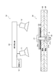
- FIG. 6 is a flowchart showing an operation example of the abnormality detection device in the first embodiment. It is a figure which shows a mode that the fixing structure in 2nd Embodiment is inspected. It is explanatory drawing of the fixing structure in 3rd Embodiment.
- FIG. 1 is a perspective view showing an example of a fixing structure 20 according to the first embodiment.
- a bolt 21 and a nut 22 (not shown) are used as fasteners for steel materials of structures such as bridges and steel towers is illustrated.
- the two steel plates 25 and 26 are fixed by a large number of bolts 21 and nuts 22.
- a washer 23 and a spacer 24 are put under the bolt 21.
- FIG. 2 shows how the fixing structure 20 in the first embodiment is inspected by using the abnormality detection device 10.
- the fixing structure 20 shown in FIG. 2 has a sectional structure taken along the line AA of FIG.
- the fixing structure 20 is made of a conductor and includes a bolt 21, a nut 22, and a washer 23 that fix the steel plates 25 and 26, and a spacer 24 that is made of an insulator and arranged between the steel plates 25 and 26 and the washer 23.
- the steel plates 25 and 26 are examples of parts having high electrical conductivity.
- the bolt 21 is inserted into the hole H formed in the steel plates 25 and 26, and the nut 22 is fitted and fixed to the threaded portion 21c of the bolt 21 protruding to the opposite side.
- the neck portion 21 a of the bolt 21 does not directly contact the steel plate 25. Since the diameter of the bolt 21 is smaller than the diameter of the hole H, normally, the bolt 21 and the steel plates 25 and 26 are not electrically connected.
- the under-neck portion 21b of the bolt 21 may be coated.
- the diameters of the washer 23 and the spacer 24 are not particularly limited and may be the same as the diameter of the bolt 21.
- the abnormality detection device 10 is a device that detects an abnormality in the fixed structure 20, and includes a transmission antenna 11 that radiates an electromagnetic wave to the fixed structure 20, a reception antenna 12 that receives the electromagnetic wave reflected by the fixed structure 20, and a transmission antenna 11.
- the frequency characteristic of the radiated electromagnetic wave is changed to obtain the frequency characteristic of the standing wave received by the receiving antenna 12, and the abnormality of the fixed structure 20 is detected by comparing the frequency characteristic with the frequency characteristic in a normal state.
- the abnormality detector 13 is provided.
- a method for detecting an abnormality of the fixed structure 20 will be specifically described.
- the washer 23 composed of the metal steel plates 25 and 26 and the conductor is mechanically fixed by the bolt 21 via the spacer 24.
- the bolt 21 is mechanically fixed by a nut 22 on the opposite side of the steel plates 25 and 26. Further, the nut 22 is in electrical contact with the steel plates 25 and 26.
- the washer 23, the bolt 21, and the steel plates 25 and 26 can be regarded as a transmission line short-circuited by the bolt 21 while the washer 23 and the bolt 21 are signal lines and the steel plates 25 and 26 are ground planes.
- the wavelength of the electromagnetic wave radiated from the transmitting antenna 11 is the electric length obtained by dividing the radius of the washer 23 by the square root of the dielectric constant of the spacer 24, and the thickness of the steel plates 25 and 26 is the steel plates 25 and 26 and the bolt 21.
- a standing wave is generated when it becomes an integral multiple of 4 times the sum of electrical lengths divided by the square root of the permittivity of the dielectric material in between.
- a part of the electromagnetic wave radiated from the transmitting antenna 11 is reflected by the washer 23 and reaches the receiving antenna 12. Since the intensity of reflection becomes stronger or weaker due to the generation of the standing wave, the frequency characteristic of the reflection intensity also changes when the frequency of the standing wave changes.
- the initial frequency characteristic (normal frequency characteristic in the initial state) is acquired by the abnormality detector 13 and stored.
- the receiving antenna 12 receives not only the electromagnetic wave reflected by the washer 23 but also the electromagnetic wave reflected by the steel plates 25 and 26.
- the electromagnetic waves reflected by the steel plates 25/26 also change, so the transmission antenna 11/reception antenna 12 and the steel plate 25 when the first frequency characteristic is acquired.
- the distance of 26 is measured by the distance measuring sensor 14 and stored.
- the distance measuring sensor 14 measures the distance between the transmitting antenna 11/receiving antenna 12 and the steel plates 25 and 26, and after confirming that the distance is the same as when the first frequency characteristic was acquired, The frequency characteristic is acquired by the abnormality detector 13.
- the frequency characteristic acquired by the abnormality detector 13 has not changed from the initial frequency characteristic, it is determined that the fixing of the bolt 21 and the nut 22 is normal.
- the frequency characteristic acquired by the abnormality detector 13 has changed from the initial frequency characteristic, it is determined that the fixing of the bolt 21 and the nut 22 is abnormal, and that effect is notified to an external device such as a PC or a tablet. Notice.
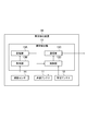
- FIG. 3 is a functional block diagram of the abnormality detection device 10 according to the first embodiment.
- the abnormality detecting device 10 is a device for detecting an abnormality of the fixed structure 20, and includes a transmitting antenna 11, a receiving antenna 12, an abnormality detector 13, and a distance measuring sensor 14 as shown in FIG. ..
- the abnormality detector 13 includes a storage unit 13A, an acquisition unit 13B, a communication unit 13C, and a control unit 13D.
- the storage unit 13A is a storage device that stores various kinds of data (for example, data indicating a frequency range including a frequency peak in a normal state).
- the acquisition unit 13B is a functional unit that acquires the sensor value of the distance measuring sensor 14.
- the communication unit 13C is a functional unit that communicates with an external device such as a PC or a tablet.
- the control unit 13D is a functional unit that controls each unit such as the transmitting antenna 11 and the receiving antenna 12 and performs various control processes necessary for detecting an abnormality.
- FIG. 4 is a flowchart showing an operation example of the abnormality detection device 10 according to the first embodiment.
- the configuration of the abnormality detection device 10 will be described together with its operation with reference to FIG.
- the abnormality detection device 10 is brought close to the fixed structure 20 to be inspected, and the distance between the fixed structure 20 and the abnormality detection device 10 is measured (steps S1 ⁇ S2).
- the transmitting antenna 11 emits an electromagnetic wave
- the frequency of the electromagnetic wave is changed
- a standing wave is generated.
- the frequency characteristic at that time is stored (steps S3 ⁇ S4 ⁇ S5 ⁇ S6 ⁇ S7).
- the predetermined distance is specifically the distance between the transmitting antenna 11/receiving antenna 12 and the steel plates 25/26 when the first frequency characteristic is acquired (distance in the initial state).
- the frequency characteristic thus stored is compared with the frequency characteristic stored first (steps S8 ⁇ S9). At this time, if the change amount of both is smaller than the threshold value, it is determined that the bolt 21 and the nut 22 are loose (normal) (steps S9 ⁇ S10). On the other hand, when the change amount of both is larger than the threshold value, it is determined that the bolt 21 and the nut 22 are loose (abnormal) (steps S9 ⁇ S11). For example, a frequency at which the intensity of the electromagnetic wave has a peak is detected, and when a phenomenon in which the peak disappears or the peak shifts occurs, it is determined that the bolt 21 and the nut 22 are loose (abnormal).
- the abnormality detection device 10 may use the distance measuring sensor 14 to perform distance correction (estimation) of the reflection intensity.
- the looseness of the bolt 21 and the nut 22 based on the result of comparison with the frequency characteristic when the bolt 21 and the nut 22 are normally fixed. Is. Therefore, the looseness can be detected by measuring one of the bolt 21 and the nut 22 installed at a location where it is difficult to visually monitor remotely, and the looseness rotated by an integral multiple of 360 degrees can also be detected.
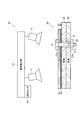
- FIG. 5 is a diagram showing a state of inspecting the fixing structure 20 according to the second embodiment. This is different from the first embodiment in that a conductive material 27 for converting the frequency of the standing wave and an insulating material 28 thinner than the spacer 24 are added. Others are the same as those in the first embodiment.
- the size of the bolt 21 and the washer 23 is determined by the structure, so it may be difficult to generate a desired standing wave. Therefore, in the second embodiment, as shown in FIG. 5, the bolt 21/washer 23 and the conductive material 27 are electrically connected.
- the radius of the washer 23 is divided by the square root of the dielectric constant of the spacer 24, and the thickness of the steel plates 25 and 26 is divided by the square root of the dielectric constant of the dielectric between the steel plates 25 and 26 and the bolt 21.
- a standing wave is generated at a frequency having an integral multiple of 4 times the length obtained by adding the electric length obtained by dividing the length of the conductive material 27 by the square root of the dielectric constant of the insulating material 28 to the electric length. Therefore, it is possible to generate a desired standing wave by adjusting the length of the conductive material 27.
- the bolt 21 and the nut 22 are compared with the frequency characteristic when the bolt 21 and the nut 22 are normally fixed, and It is possible to detect looseness of the nut 22. Further, it is possible to generate a desired standing wave by adjusting the length of the conductive material 27.
- the conductive material 27 and the insulating material 28 are drawn only on the left side of the bolt 21 and the washer 23, but the area where the conductive material 27 and the insulating material 28 are provided can be appropriately adjusted. is there. Similar to the bolt 21 side, the conductive material 27 and the insulating material 28 may be provided on the nut 22 side.
- the insulating material 28 thinner than the thickness of the spacer 24 is added, but the thickness of the insulating material 28 can be appropriately adjusted. That is, any structure may be used as long as it electrically connects the bolt 21/washer 23 and the conductive material 27.
- FIG. 6A is a cross-sectional view of the fixing structure 20 according to the third embodiment
- FIG. 6B is a plan view of the fixing structure 20 according to the third embodiment.
- a spacer 24a and a washer 23a are also provided on the nut 22 side, and the conductive material 27 on the bolt 21 side is formed into a planar antenna shape to improve the coupling efficiency with the antennas 11 and 12 of the abnormality detection device 10. Then, the antennas 11 and 12 of the abnormality detection device 10 are made one type.
- the planar antenna By forming the planar antenna with the conductive material 27, electromagnetic waves radiated from the angle of the main lobe of the planar antenna of the conductive material 27 are efficiently received by the planar antenna, and at the same time, the energy of the reflected electromagnetic waves is also included in the main lobe. Is emitted at an angle of. Therefore, when the abnormality detection device 10 is installed at a position where the main lobes of the antennas 11 and 12 of the abnormality detection device 10 and the main lobe of the planar antenna of the conductive material 27 overlap, the transmission antenna 11 of the abnormality detection device 10 emits radiation. The electromagnetic wave reflected by the nut 22 can be efficiently received by the receiving antenna 12 of the abnormality detection device 10. Since the intensity of reflection becomes stronger or weaker due to the generation of the standing wave, the frequency characteristic of the reflection intensity also changes when the frequency of the standing wave changes.
- the first frequency characteristic is acquired by the abnormality detector 13 and stored. After that, as in the first embodiment, if the frequency characteristic acquired by the abnormality detector 13 does not change from the initial frequency characteristic, it is determined that the fixing of the bolt 21 and the nut 22 is normal. On the other hand, if the frequency characteristic acquired by the abnormality detector 13 has changed from the initial frequency characteristic, it is determined that the fixing of the bolt 21 and the nut 22 is abnormal, and the fact is notified to an external device such as a PC or a tablet. Notice.
- the bolt 21 and the nut 22 are compared with the frequency characteristic when the bolt 21 and the nut 22 are normally fixed, based on the result of comparison. It is possible to detect looseness of the nut 22. Further, the conductive material 27 can be formed into a planar antenna shape to improve the coupling efficiency with the antennas 11 and 12 of the abnormality detection device 10.
- FIG. 6B a simple rectangular antenna shape is illustrated, but various antenna shapes such as a circular shape and a square shape can be adopted. Even when such an antenna shape is adopted, the length of the line L in the figure is converted into a wavelength when the frequency actually used is converted into a wavelength so that the wavelength resonates with the electromagnetic wave radiated from the transmission antenna 11. Design for integer multiples.
- the abnormality detection device 10 is configured by the conductor, and is configured by the bolt 21, the nut 22, and the washer 23 that fix the steel plates 25 and 26, and the insulator, and the steel plates 25 and 26.
- An anomaly detection device 10 for detecting an anomaly of a fixed structure 20 including a spacer 24 arranged between a fixed structure 20 and a washer 23, the transmitting antenna 11 radiating an electromagnetic wave to the fixed structure 20, and the fixed structure 20.
- the frequency characteristic of the standing wave received by the receiving antenna 12 is acquired by changing the frequency of the electromagnetic wave radiated from the receiving antenna 12 that receives the electromagnetic wave and the transmitting antenna 11, and the frequency characteristic is set to the frequency characteristic in a normal state.
- An abnormality detector 13 for detecting an abnormality of the fixed structure 20 by comparison is provided.
- the receiving antenna 12 receives the standing wave excited by radiating an electromagnetic wave to the bolt 21 and the nut 22 to be inspected, and changes from the change in the frequency characteristic when the receiving antenna 12 tightens the bolt 21 and the nut 21. It is possible to detect looseness of the nut 22.
- the fixing structure 20 may include an insulating material 28 formed on the steel plates 25 and 26, and a conductive material 27 formed on the insulating material 28 and electrically connected to the washer 23. .. Thereby, it is possible to generate a desired standing wave by adjusting the length of the conductive material 27.
- the fixing structure 20 may also include a spacer 24a and a washer 23a on the nut 22 side, and the conductive material 27 on the bolt 21 side may have a planar antenna shape. This makes it possible to form the conductive material 27 into a planar antenna shape and improve the coupling efficiency with the antennas 11 and 12 of the abnormality detection device 10.
- a distance measuring sensor 14 for measuring the distance between the transmitting antenna 11 and the receiving antenna 12 and the steel plates 25 and 26 is provided, and the abnormality detector 13 determines that the distance measured by the distance measuring sensor 14 is the same as that in a normal state. After confirming that there is, an abnormality in the fixed structure 20 may be detected. That is, in the case of fixed-point measurement with a fixed distance, the distance measuring sensor 14 is not necessary, but when the distance changes, the distance measuring sensor 14 can be used to correct the distance of the reflection intensity.
- the present invention can be realized not only as such an abnormality detection device 10 but also as a fixed structure 20 that is an inspection target of such an abnormality detection device 10.
- Abnormality Detection Device 11 Transmission Antenna 12 Reception Antenna 13 Abnormality Detector 14 Distance Measuring Sensor 20 Fixed Structure 21 Bolt 22 Nut 23 Washer 24 Spacer 25 Steel Plate 26 Steel Plate 27 Conductive Material 28 Insulating Material
Landscapes
- Engineering & Computer Science (AREA)
- Physics & Mathematics (AREA)
- General Physics & Mathematics (AREA)
- General Engineering & Computer Science (AREA)
- Aviation & Aerospace Engineering (AREA)
- Analytical Chemistry (AREA)
- Life Sciences & Earth Sciences (AREA)
- Chemical & Material Sciences (AREA)
- Health & Medical Sciences (AREA)
- Biochemistry (AREA)
- General Health & Medical Sciences (AREA)
- Immunology (AREA)
- Pathology (AREA)
- Electromagnetism (AREA)
- Mechanical Engineering (AREA)
- Measurement Of Length, Angles, Or The Like Using Electric Or Magnetic Means (AREA)
Abstract
ボルトやナットなどの留め具の異常を検出するのに好適な異常検出装置および固定構造を提供する。異常検出装置10は、導体で構成され、鋼板25・26を固定するボルト21、ナット22、およびワッシャー23と、絶縁体で構成され、鋼板25・26とワッシャー23との間に配置されるスペーサ24とを備える固定構造20の異常を検出する異常検出装置10であって、固定構造20に電磁波を放射する送信アンテナ11と、固定構造20で反射した電磁波を受信する受信アンテナ12と、送信アンテナ11より放射される電磁波の周波数を変えて受信アンテナ12により受信される定在波の周波数特性を取得し、その周波数特性を正常な状態における周波数特性と比較することで固定構造20の異常を検出する異常検出器13とを備える。
Description
本発明は、異常検出装置および固定構造に関し、主として、ボルトやナットなどの留め具の異常を検出するための技術に関する。
橋梁や鉄塔などの構造物の鋼材の留め具として使用されているボルトとナットは、構造物の振動により緩むことがあり大きな事故の引き金となる。これを防ぐために非特許文献1のようにボルト・ナットを固定した時の回転軸方向の角度をマークする方法がある。
「ネジ緩みの早期発見のポイント」、2018年11月12日検索、インターネット<URL:http://maintenance119.com/screw/point03_scr.html>
しかし、非特許文献1の方法では点検者が目視で確認できるようにボルト・ナットの個所まで近づく必要があるため橋の下や鉄塔の上部に設置されたボルト・ナットの点検への適用は難しい。また、ボルトとナットのどちらが回転するか不明なためボルト・ナット両方を点検する必要がある。さらに、ボルト・ナットが360度の整数倍回転した緩みの場合であっても同じ場所にマークが戻るため緩みがない場合と変化が無いように見える。屋外の構造物に標識したマークは紫外線や風雪により劣化し見えなくなる可能性もある。
本発明は、この課題に鑑みてなされたものであり、ボルトやナットなどの留め具の異常を検出するのに好適な異常検出装置および固定構造を提供することを目的とする。
上記目的を達成するため、第1の態様に係る発明は、導体で構成され、部品を固定するボルト、ナット、およびワッシャーと、絶縁体で構成され、前記部品と前記ワッシャーとの間に配置されるスペーサとを備える固定構造の異常を検出する異常検出装置であって、前記固定構造に電磁波を放射する送信アンテナと、前記固定構造で反射した電磁波を受信する受信アンテナと、前記送信アンテナより放射される電磁波の周波数を変えて前記受信アンテナにより受信される定在波の周波数特性を取得し、その周波数特性を正常な状態における周波数特性と比較することで前記固定構造の異常を検出する異常検出器とを備えることを要旨とする。
第2の態様に係る発明は、第1の態様に係る発明において、前記固定構造が、前記部品上に形成される絶縁性材料と、前記絶縁性材料上に形成され、前記ワッシャーと電気的に接続される導電性材料とを備えることを要旨とする。
第3の態様に係る発明は、第2の態様に係る発明において、前記固定構造が、前記ナット側にも前記スペーサおよび前記ワッシャーを備え、前記ボルト側の前記導電性材料の形状が平面アンテナ形状であることを要旨とする。
第4の態様に係る発明は、第1から第3のいずれか1つの態様に係る発明において、前記送信アンテナおよび前記受信アンテナと前記部品の距離を測定する測距センサを備え、前記異常検出器が、前記測距センサにより測定された距離が正常な状態における距離と同じであることを確認したのち、前記固定構造の異常を検出することを要旨とする。
第5の態様に係る発明は、第1から第4のいずれか1つの態様に係る構造を備えることを特徴とする固定構造であることを要旨とする。
本発明によれば、ボルトやナットなどの留め具の異常を検出するのに好適な異常検出装置および固定構造を提供することが可能である。
以下、本発明の実施形態について図面を参照して詳細に説明する。なお、図面の記載において、同一または類似の部分には同一または類似の符号を付している。ただし、図面は模式的なものであり、厚みと平面寸法との関係、各層の厚みの比率などは現実のものとは異なることに留意すべきである。したがって、具体的な厚みや寸法は以下の説明を参酌して判断すべきものである。また、図面相互間においても互いの寸法の関係や比率が異なる部分が含まれていることは勿論である。
≪第1の実施形態≫
図1は、第1の実施形態における固定構造20の一例を示す斜視図である。ここでは、橋梁や鉄塔などの構造物の鋼材の留め具としてボルト21とナット22(図示せず)を使用している場合を例示している。具体的には、二つの鋼板25・26を多数のボルト21とナット22で固定している。ボルト21の下にはワッシャー23とスペーサ24を入れている。
図1は、第1の実施形態における固定構造20の一例を示す斜視図である。ここでは、橋梁や鉄塔などの構造物の鋼材の留め具としてボルト21とナット22(図示せず)を使用している場合を例示している。具体的には、二つの鋼板25・26を多数のボルト21とナット22で固定している。ボルト21の下にはワッシャー23とスペーサ24を入れている。
図2は、第1の実施形態における固定構造20を異常検出装置10を用いて点検する様子を示している。図2の固定構造20は、図1のA-A線に沿う断面構成を示している。
固定構造20は、導体で構成され、鋼板25・26を固定するボルト21、ナット22、およびワッシャー23と、絶縁体で構成され、鋼板25・26とワッシャー23との間に配置されるスペーサ24とを備える。鋼板25・26は、電気伝導性の高い部品の一例である。鋼板25・26に空けられた孔Hにボルト21が挿入され、反対側に突出したボルト21のねじが切られた部分21cにナット22が嵌められて固定される。ボルト21の首部21aは、直接、鋼板25に接触しない。ボルト21の径は、孔Hの径よりもが小さいので、通常、ボルト21と鋼板25・26は電気的に導通しない。ボルト21が孔Hに対して偏心して挿入され、ボルト21が孔Hと接触してしまうおそれがある場合は、ボルト21の首下部分21bを被覆加工してもよい。ワッシャー23とスペーサ24の径は特に限定されるものではなく、ボルト21の径と同程度であってもよい。
異常検出装置10は、固定構造20の異常を検出する装置であって、固定構造20に電磁波を放射する送信アンテナ11と、固定構造20で反射した電磁波を受信する受信アンテナ12と、送信アンテナ11より放射される電磁波の周波数を変えて受信アンテナ12により受信される定在波の周波数特性を取得し、その周波数特性を正常な状態における周波数特性と比較することで固定構造20の異常を検出する異常検出器13とを備える。以下、固定構造20の異常を検出する方法について具体的に説明する。
ボルト21とナット22が正常に鋼板25・26に固定されている状態では、金属製の鋼板25・26と導体で構成されるワッシャー23はスペーサ24を介してボルト21により機械的に固定されており、ボルト21は鋼板25・26の反対側のナット22により機械的に固定されている。また、ナット22は鋼板25・26と電気的に接触している。この状態では、ワッシャー23とボルト21を信号線、鋼板25・26をグランドプレーンとして、ワッシャー23・ボルト21・鋼板25・26をボルト21により短絡された伝送線とみなすことができる。このため、送信アンテナ11から放射される電磁波の波長が、ワッシャー23の半径をスペーサ24の誘電率の平方根で除算した電気長と、鋼板25・26の厚さを鋼板25・26とボルト21の間の誘電体の誘電率の平方根で除算した電気長の和の4倍の整数倍となった場合に定在波が発生する。
ナット22が緩んだ状態では、正常な状態では短絡であったナット22と鋼板25・26の間に寄生容量が生じるため、定在波が発生する電磁波の周波数が変化する。この定在波の発生する周波数の変化を検出することによりボルト21・ナット22の固定の異常を検出することができる。
送信アンテナ11から放射された電磁波の一部はワッシャー23により反射され受信アンテナ12に到達する。反射の強度は定在波の発生により強くなったり弱くなったりするため、定在波の発生する周波数が変化すると反射強度の周波数特性も変化する。
そこで、ボルト21・ナット22が固定された状態で、はじめの周波数特性(初期状態の正常な周波数特性)を異常検出器13で取得し記憶する。このとき、受信アンテナ12はワッシャー23で反射された電磁波だけでなく鋼板25・26で反射された電磁波も受信する。送信アンテナ11・受信アンテナ12と鋼板25・26の距離が変化すると鋼板25・26で反射される電磁波も変化するため、はじめの周波数特性を取得したときの送信アンテナ11・受信アンテナ12と鋼板25・26の距離を測距センサ14で測定し記憶する。
点検時は、測距センサ14で送信アンテナ11・受信アンテナ12と鋼板25・26の距離を測定し、その距離がはじめの周波数特性を取得したときの距離と同じであることを確認したのち、異常検出器13で周波数特性を取得する。ここで、異常検出器13で取得した周波数特性がはじめの周波数特性から変化していなければボルト21・ナット22の固定が正常な状態であると判断する。一方、異常検出器13で取得した周波数特性がはじめの周波数特性から変化していればボルト21・ナット22の固定が異常な状態であると判断し、その旨をPCやタブレットなどの外部装置に通知する。
図3は、第1の実施形態における異常検出装置10の機能ブロック図である。この異常検出装置10は、固定構造20の異常を検出する装置であって、図3に示すように、送信アンテナ11と、受信アンテナ12と、異常検出器13と、測距センサ14とを備える。異常検出器13は、記憶部13Aと、取得部13Bと、通信部13Cと、制御部13Dとを備える。記憶部13Aは、各種のデータ(例えば、正常な状態の周波数のピークを含む周波数範囲を示すデータ)を記憶する記憶装置である。取得部13Bは、測距センサ14のセンサ値を取得する機能部である。通信部13Cは、PCやタブレットなどの外部装置と通信を行う機能部である。制御部13Dは、送信アンテナ11や受信アンテナ12などの各部を制御するとともに、異常を検出するために必要な各種の制御処理を実施する機能部である。
図4は、第1の実施形態における異常検出装置10の動作例を示すフローチャートである。以下、図4を用いて異常検出装置10の構成をその動作とともに説明する。
まず、点検対象である固定構造20に異常検出装置10を近づけ、固定構造20と異常検出装置10との間の距離を測定する(ステップS1→S2)。次いで、固定構造20と異常検出装置10との間の距離が所定の距離になったことを確認すると、送信アンテナ11から電磁波を放射し、電磁波の周波数を変化させ、定在波を発生させ、そのときの周波数特性を記憶する(ステップS3→S4→S5→S6→S7)。所定の距離とは、具体的には、はじめの周波数特性を取得したときの送信アンテナ11・受信アンテナ12と鋼板25・26の距離(初期状態の距離)である。次いで、このように記憶した周波数特性をはじめに記憶しておいた周波数特性と比較する(ステップS8→S9)。このとき、両者の変化量が閾値より小さい場合は、ボルト21・ナット22の緩みなし(正常)と判断する(ステップS9→S10)。一方、両者の変化量が閾値より大きい場合は、ボルト21・ナット22の緩みあり(異常)と判断する(ステップS9→S11)。例えば、電磁波の強度がピークとなる周波数を検出し、ピークが消失するとかピークがシフトする現象が起こったときに、ボルト21・ナット22の緩みあり(異常)と判断するようになっている。
なお、ここでは、固定構造20と異常検出装置10との間の距離が初期状態の距離になったことを確認することとしているが、これに限定されるものではない。すなわち、異常検出装置10が測距センサ14を使用して反射強度の距離補正(推定)を行うようにしてもよい。
以上のように、第1の実施形態によれば、ボルト21とナット22が正常に固定されている際の周波数特性と比較した結果に基づいてボルト21とナット22の緩みを検出することが可能である。そのため、遠隔から目視監視が難しい個所に設置されたボルト21・ナット22の一方の測定で緩みを検出でき、360度の整数倍回転した緩みも検出できる。
≪第2の実施形態≫
以下、第2の実施形態について説明する。以下の説明では、第1の実施形態と異なる点を中心に説明することとし、同じ点については詳しい説明を割愛する。
以下、第2の実施形態について説明する。以下の説明では、第1の実施形態と異なる点を中心に説明することとし、同じ点については詳しい説明を割愛する。
図5は、第2の実施形態における固定構造20を点検する様子を示す図である。第1の実施形態とは、定在波の発生する周波数を変換する導電性材料27とスペーサ24の厚さより薄い絶縁性材料28を加えたところが異なる。その他は第1の実施形態と同じである。
一般にボルト21・ワッシャー23のサイズは構造物によって決まるため、所望の定在波を発生させることが難しい場合がある。そこで、第2の実施形態では、図5に示すように、ボルト21・ワッシャー23と導電性材料27を電気的に接続している。これにより、ワッシャー23の半径をスペーサ24の誘電率の平方根で除算した電気長と、鋼板25・26の厚さを鋼板25・26とボルト21の間の誘電体の誘電率の平方根で除算した電気長に、導電性材料27の長さを絶縁性材料28の誘電率の平方根で除算した電気長を加えた長さの4倍の整数倍を波長とする周波数で定在波が発生する。そのため、導電性材料27の長さを調整することで所望の定在波を発生させることが可能である。
以上のように、第2の実施形態によれば、第1の実施形態と同じ原理で、ボルト21とナット22が正常に固定されている際の周波数特性と比較した結果に基づいてボルト21とナット22の緩みを検出することが可能である。また、導電性材料27の長さを調整することで所望の定在波を発生させることが可能である。
なお、図5では、ボルト21・ワッシャー23の左側だけに導電性材料27・絶縁性材料28を描いているが、導電性材料27・絶縁性材料28を設ける領域は適宜調整することが可能である。ボルト21側と同様、ナット22側に導電性材料27・絶縁性材料28を設けることも可能である。
また、上記の説明では、スペーサ24の厚さより薄い絶縁性材料28を加えることとしているが、絶縁性材料28の厚さは適宜調整することが可能である。すなわち、ボルト21・ワッシャー23と導電性材料27を電気的に接続する構成であればよい。
≪第3の実施形態≫
以下、第3の実施形態について説明する。以下の説明では、第2の実施形態と異なる点を中心に説明することとし、同じ点については詳しい説明を割愛する。
以下、第3の実施形態について説明する。以下の説明では、第2の実施形態と異なる点を中心に説明することとし、同じ点については詳しい説明を割愛する。
図6(a)は、第3の実施形態における固定構造20の断面図であり、図6(b)は、第3の実施形態における固定構造20の平面図である。第3の実施形態では、ナット22側にもスペーサ24aおよびワッシャー23aを備え、ボルト21側の導電性材料27の形状を平面アンテナ形状にして異常検出装置10のアンテナ11・12と結合効率を向上させ、異常検出装置10のアンテナ11・12を1種にした。
導電性材料27で平面アンテナを形成することにより、導電性材料27の平面アンテナのメインローブの角度から放射される電磁波が効率よく平面アンテナに受信されると同時に反射される電磁波のエネルギーもメインローブの角度に放射される。このため、異常検出装置10のアンテナ11・12のメインローブと導電性材料27の平面アンテナのメインローブが重なる位置に異常検出装置10が設置されたとき、異常検出装置10の送信アンテナ11から放射されナット22で反射された電磁波を異常検出装置10の受信アンテナ12により効率よく受信することができる。反射の強度は定在波の発生により強くなったり弱くなったりするため、定在波の発生する周波数が変化すると反射強度の周波数特性も変化する。
そこで、ボルト21・ナット22を固定された状態で、はじめの周波数特性を異常検出器13で取得し記憶する。その後は第1の実施形態と同様、異常検出器13で取得した周波数特性がはじめの周波数特性から変化していなければボルト21・ナット22の固定が正常な状態であると判断する。一方、異常検出器13で取得した周波数特性がはじめの周波数特性から変化していればボルト21・ナット22の固定が異常な状態であると判断し、その旨をPCやタブレットなどの外部装置に通知する。
以上のように、第3の実施形態によれば、第1の実施形態と同じ原理で、ボルト21とナット22が正常に固定されている際の周波数特性と比較した結果に基づいてボルト21とナット22の緩みを検出することが可能である。また、導電性材料27を平面アンテナ形状にして異常検出装置10のアンテナ11・12と結合効率を向上させることが可能である。
なお、図6(b)では、長方形のシンプルなアンテナ形状を例示しているが、アンテナ形状は円状や正方形など様々な形状を採用することができる。このようなアンテナ形状を採用する場合も、送信アンテナ11から放射される電磁波と共振するような波長となるように、図中のラインLの長さが実際に使う周波数を波長に換算したときの整数倍に対応する設計を行う。
≪まとめ≫
以上のように、本発明の実施形態における異常検出装置10は、導体で構成され、鋼板25・26を固定するボルト21、ナット22、およびワッシャー23と、絶縁体で構成され、鋼板25・26とワッシャー23との間に配置されるスペーサ24とを備える固定構造20の異常を検出する異常検出装置10であって、固定構造20に電磁波を放射する送信アンテナ11と、固定構造20で反射した電磁波を受信する受信アンテナ12と、送信アンテナ11より放射される電磁波の周波数を変えて受信アンテナ12により受信される定在波の周波数特性を取得し、その周波数特性を正常な状態における周波数特性と比較することで固定構造20の異常を検出する異常検出器13とを備える。これにより、点検対象のボルト21・ナット22に対して、電磁波を放射して励起される定在波を受信アンテナ12で受信し、締まっている際の周波数特性と比較した変化から、ボルト21とナット22の緩みを検出することが可能である。
以上のように、本発明の実施形態における異常検出装置10は、導体で構成され、鋼板25・26を固定するボルト21、ナット22、およびワッシャー23と、絶縁体で構成され、鋼板25・26とワッシャー23との間に配置されるスペーサ24とを備える固定構造20の異常を検出する異常検出装置10であって、固定構造20に電磁波を放射する送信アンテナ11と、固定構造20で反射した電磁波を受信する受信アンテナ12と、送信アンテナ11より放射される電磁波の周波数を変えて受信アンテナ12により受信される定在波の周波数特性を取得し、その周波数特性を正常な状態における周波数特性と比較することで固定構造20の異常を検出する異常検出器13とを備える。これにより、点検対象のボルト21・ナット22に対して、電磁波を放射して励起される定在波を受信アンテナ12で受信し、締まっている際の周波数特性と比較した変化から、ボルト21とナット22の緩みを検出することが可能である。
また、固定構造20は、鋼板25・26上に形成される絶縁性材料28と、絶縁性材料28上に形成され、ワッシャー23と電気的に接続される導電性材料27とを備えてもよい。これにより、導電性材料27の長さを調整することで所望の定在波を発生させることが可能である。
また、固定構造20は、ナット22側にもスペーサ24aおよびワッシャー23aを備え、ボルト21側の導電性材料27の形状が平面アンテナ形状であってもよい。これにより、導電性材料27を平面アンテナ形状にして異常検出装置10のアンテナ11・12と結合効率を向上させることが可能である。
また、送信アンテナ11および受信アンテナ12と鋼板25・26の距離を測定する測距センサ14を備え、異常検出器13は、測距センサ14により測定された距離が正常な状態における距離と同じであることを確認したのち、固定構造20の異常を検出してもよい。すなわち、距離固定の定点測定の場合、測距センサ14は不要であるが、距離が変化した場合、測距センサ14を使用して反射強度の距離補正を行うことが可能である。
なお、本発明はこのような異常検出装置10として実現することができるだけでなく、このような異常検出装置10の点検対象である固定構造20としても実現することができる。
≪その他の実施形態≫
上記のように、いくつかの実施形態について記載したが、開示の一部をなす論述および図面は例示的なものであり、限定するものであると理解すべきではない。この開示から当業者には様々な代替実施形態、実施例および運用技術が明らかとなろう。
上記のように、いくつかの実施形態について記載したが、開示の一部をなす論述および図面は例示的なものであり、限定するものであると理解すべきではない。この開示から当業者には様々な代替実施形態、実施例および運用技術が明らかとなろう。
10 異常検出装置
11 送信アンテナ
12 受信アンテナ
13 異常検出器
14 測距センサ
20 固定構造
21 ボルト
22 ナット
23 ワッシャー
24 スペーサ
25 鋼板
26 鋼板
27 導電性材料
28 絶縁性材料
11 送信アンテナ
12 受信アンテナ
13 異常検出器
14 測距センサ
20 固定構造
21 ボルト
22 ナット
23 ワッシャー
24 スペーサ
25 鋼板
26 鋼板
27 導電性材料
28 絶縁性材料
Claims (5)
- 導体で構成され、部品を固定するボルト、ナット、およびワッシャーと、
絶縁体で構成され、前記部品と前記ワッシャーとの間に配置されるスペーサと
を備える固定構造の異常を検出する異常検出装置であって、
前記固定構造に電磁波を放射する送信アンテナと、
前記固定構造で反射した電磁波を受信する受信アンテナと、
前記送信アンテナより放射される電磁波の周波数を変えて前記受信アンテナにより受信される定在波の周波数特性を取得し、その周波数特性を正常な状態における周波数特性と比較することで前記固定構造の異常を検出する異常検出器と
を備えることを特徴とする異常検出装置。 - 前記固定構造は、
前記部品上に形成される絶縁性材料と、
前記絶縁性材料上に形成され、前記ワッシャーと電気的に接続される導電性材料と
を備えることを特徴とする請求項1に記載の異常検出装置。 - 前記固定構造は、
前記ナット側にも前記スペーサおよび前記ワッシャーを備え、
前記ボルト側の前記導電性材料の形状が平面アンテナ形状である
ことを特徴とする請求項2に記載の異常検出装置。 - 前記送信アンテナおよび前記受信アンテナと前記部品の距離を測定する測距センサを備え、
前記異常検出器は、前記測距センサにより測定された距離が正常な状態における距離と同じであることを確認したのち、前記固定構造の異常を検出することを特徴とする請求項1から3のいずれか1項に記載の異常検出装置。 - 請求項1から4のいずれか1項に記載の構造を備えることを特徴とする固定構造。
Priority Applications (1)
| Application Number | Priority Date | Filing Date | Title |
|---|---|---|---|
| US17/292,674 US12012988B2 (en) | 2018-12-05 | 2019-11-21 | Abnormality detection device and fixing structure |
Applications Claiming Priority (2)
| Application Number | Priority Date | Filing Date | Title |
|---|---|---|---|
| JP2018227890A JP7177347B2 (ja) | 2018-12-05 | 2018-12-05 | 異常検出装置および固定構造 |
| JP2018-227890 | 2018-12-05 |
Publications (1)
| Publication Number | Publication Date |
|---|---|
| WO2020116173A1 true WO2020116173A1 (ja) | 2020-06-11 |
Family
ID=70975458
Family Applications (1)
| Application Number | Title | Priority Date | Filing Date |
|---|---|---|---|
| PCT/JP2019/045537 Ceased WO2020116173A1 (ja) | 2018-12-05 | 2019-11-21 | 異常検出装置および固定構造 |
Country Status (3)
| Country | Link |
|---|---|
| US (1) | US12012988B2 (ja) |
| JP (1) | JP7177347B2 (ja) |
| WO (1) | WO2020116173A1 (ja) |
Cited By (1)
| Publication number | Priority date | Publication date | Assignee | Title |
|---|---|---|---|---|
| US11949225B2 (en) | 2022-05-04 | 2024-04-02 | Buyers Products Company | System for detecting and comparing current in a motor |
Families Citing this family (3)
| Publication number | Priority date | Publication date | Assignee | Title |
|---|---|---|---|---|
| JP7364941B2 (ja) * | 2020-01-24 | 2023-10-19 | 日本電信電話株式会社 | 緩み検出センサ及びそれを用いた緩み検出方法 |
| CN111896559B (zh) * | 2020-08-21 | 2022-11-25 | 爱德森(厦门)电子有限公司 | 一种隐形材料性能衰变点频式检测方法及其系统装置 |
| CN116826382B (zh) * | 2023-04-17 | 2026-02-27 | 河南师范大学 | 一种螺栓松动检测传感器的环形重叠子贴片天线结构 |
Citations (5)
| Publication number | Priority date | Publication date | Assignee | Title |
|---|---|---|---|---|
| JP2009064111A (ja) * | 2007-09-04 | 2009-03-26 | Mitsubishi Heavy Ind Ltd | 部品管理具、部品状態管理方法及びシステム、並びに、ネジの締結状態管理方法及びシステム |
| JP2011141150A (ja) * | 2010-01-06 | 2011-07-21 | Yazaki Corp | 異常検出装置 |
| JP2013210234A (ja) * | 2012-03-30 | 2013-10-10 | Seiko Epson Corp | 締め付け緩み検出センサー及び締め付け緩み検出システム |
| US20140190267A1 (en) * | 2013-01-09 | 2014-07-10 | King Abdulaziz City For Science And Technology | Fastener tension monitoring system |
| JP2018013431A (ja) * | 2016-07-21 | 2018-01-25 | 株式会社Cq−Sネット | 定在波レーダーによる状態検知装置 |
Family Cites Families (3)
| Publication number | Priority date | Publication date | Assignee | Title |
|---|---|---|---|---|
| WO2002013159A1 (en) * | 2000-08-03 | 2002-02-14 | Jacob Hazan | Bolt tamper sensor |
| CN104851246B (zh) * | 2015-05-26 | 2017-03-22 | 重庆大学 | 用于监测螺栓断裂或松动的装置 |
| CN205228815U (zh) * | 2015-12-22 | 2016-05-11 | 长安大学 | 一种检测汽车用螺栓紧固状况的装置 |
-
2018
- 2018-12-05 JP JP2018227890A patent/JP7177347B2/ja active Active
-
2019
- 2019-11-21 WO PCT/JP2019/045537 patent/WO2020116173A1/ja not_active Ceased
- 2019-11-21 US US17/292,674 patent/US12012988B2/en active Active
Patent Citations (5)
| Publication number | Priority date | Publication date | Assignee | Title |
|---|---|---|---|---|
| JP2009064111A (ja) * | 2007-09-04 | 2009-03-26 | Mitsubishi Heavy Ind Ltd | 部品管理具、部品状態管理方法及びシステム、並びに、ネジの締結状態管理方法及びシステム |
| JP2011141150A (ja) * | 2010-01-06 | 2011-07-21 | Yazaki Corp | 異常検出装置 |
| JP2013210234A (ja) * | 2012-03-30 | 2013-10-10 | Seiko Epson Corp | 締め付け緩み検出センサー及び締め付け緩み検出システム |
| US20140190267A1 (en) * | 2013-01-09 | 2014-07-10 | King Abdulaziz City For Science And Technology | Fastener tension monitoring system |
| JP2018013431A (ja) * | 2016-07-21 | 2018-01-25 | 株式会社Cq−Sネット | 定在波レーダーによる状態検知装置 |
Cited By (1)
| Publication number | Priority date | Publication date | Assignee | Title |
|---|---|---|---|---|
| US11949225B2 (en) | 2022-05-04 | 2024-04-02 | Buyers Products Company | System for detecting and comparing current in a motor |
Also Published As
| Publication number | Publication date |
|---|---|
| JP2020091169A (ja) | 2020-06-11 |
| US12012988B2 (en) | 2024-06-18 |
| US20220010826A1 (en) | 2022-01-13 |
| JP7177347B2 (ja) | 2022-11-24 |
Similar Documents
| Publication | Publication Date | Title |
|---|---|---|
| WO2020116173A1 (ja) | 異常検出装置および固定構造 | |
| KR101539436B1 (ko) | 가스 절연 개폐기의 부분 방전 검출 장치 | |
| WO2020090446A1 (ja) | 緩み検出構造及びその構造を用いた緩み検出方法 | |
| US10502774B2 (en) | System for detecting electromagnetic discharge fields | |
| US7145453B2 (en) | Harmonic wireless transponder sensor and method | |
| CN105846057B (zh) | 一种星载偏波束设计的gnss大气掩星天线 | |
| CN110779935A (zh) | 一种瓷绝缘子本体嵌入式在线监测系统及方法 | |
| CN204631196U (zh) | 一种用于电缆局部放电检测的外置式特高频传感器 | |
| KR101838288B1 (ko) | 레이더 센서 및 이에 사용되는 반사판 | |
| Yi et al. | Wireless crack sensing using an RFID-based folded patch antenna | |
| JP7303455B2 (ja) | 緩み検出構造及びその構造を用いた緩み検出方法 | |
| CN118914778A (zh) | 内置式组合电器多参量监测传感器 | |
| WO2011081526A1 (en) | Method and system for detecting faults in laminated structures | |
| KR20060091984A (ko) | 가스 절연 개폐장치의 내장형 부분 방전 검출 센서 | |
| Matsunaga et al. | Paintable wireless passive sensor based on electromagnetic waveguide to detect loose bolts for remote infrastructure inspection | |
| US10488487B2 (en) | System for mapping electromagnetic discharge fields | |
| CN210038034U (zh) | 一种基于超宽带天线传感器的绝缘子劣化检测装置 | |
| JP2011141249A (ja) | 建造物における水分検知システムおよびこれに使用する水分検知用シート | |
| Dhara et al. | An ultra-wide band multi-layered hatch-mounted UHF partial discharge sensor for high-voltage power transformers | |
| CN114006162B (zh) | 一种车载雷达天线及车辆 | |
| CN112067959A (zh) | 高压开关柜箱壁一体式电磁超声复合传感器及安装方法 | |
| CN219074746U (zh) | 一种通用型直立式弹簧天线焊接工装 | |
| CN109460585A (zh) | 一种毫米波雷达微带天线设计标定方法 | |
| KR20170039037A (ko) | 측정장치 | |
| CN119742588B (zh) | 一种多方向窄波束定向漏缆 |
Legal Events
| Date | Code | Title | Description |
|---|---|---|---|
| 121 | Ep: the epo has been informed by wipo that ep was designated in this application |
Ref document number: 19893053 Country of ref document: EP Kind code of ref document: A1 |
|
| NENP | Non-entry into the national phase |
Ref country code: DE |
|
| 122 | Ep: pct application non-entry in european phase |
Ref document number: 19893053 Country of ref document: EP Kind code of ref document: A1 |